EP4239342A2 - Automatic analysis apparatus - Google Patents
Automatic analysis apparatus Download PDFInfo
- Publication number
- EP4239342A2 EP4239342A2 EP23176883.9A EP23176883A EP4239342A2 EP 4239342 A2 EP4239342 A2 EP 4239342A2 EP 23176883 A EP23176883 A EP 23176883A EP 4239342 A2 EP4239342 A2 EP 4239342A2
- Authority
- EP
- European Patent Office
- Prior art keywords
- unit
- specimen
- dispensing
- sensor
- dispensing mechanism
- Prior art date
- Legal status (The legal status is an assumption and is not a legal conclusion. Google has not performed a legal analysis and makes no representation as to the accuracy of the status listed.)
- Granted
Links
Images



Classifications
-
- G—PHYSICS
- G01—MEASURING; TESTING
- G01N—INVESTIGATING OR ANALYSING MATERIALS BY DETERMINING THEIR CHEMICAL OR PHYSICAL PROPERTIES
- G01N35/00—Automatic analysis not limited to methods or materials provided for in any single one of groups G01N1/00 - G01N33/00; Handling materials therefor
- G01N35/10—Devices for transferring samples or any liquids to, in, or from, the analysis apparatus, e.g. suction devices, injection devices
- G01N35/1002—Reagent dispensers
-
- G—PHYSICS
- G01—MEASURING; TESTING
- G01N—INVESTIGATING OR ANALYSING MATERIALS BY DETERMINING THEIR CHEMICAL OR PHYSICAL PROPERTIES
- G01N35/00—Automatic analysis not limited to methods or materials provided for in any single one of groups G01N1/00 - G01N33/00; Handling materials therefor
- G01N35/10—Devices for transferring samples or any liquids to, in, or from, the analysis apparatus, e.g. suction devices, injection devices
- G01N35/1009—Characterised by arrangements for controlling the aspiration or dispense of liquids
- G01N35/1011—Control of the position or alignment of the transfer device
-
- G—PHYSICS
- G01—MEASURING; TESTING
- G01N—INVESTIGATING OR ANALYSING MATERIALS BY DETERMINING THEIR CHEMICAL OR PHYSICAL PROPERTIES
- G01N35/00—Automatic analysis not limited to methods or materials provided for in any single one of groups G01N1/00 - G01N33/00; Handling materials therefor
- G01N2035/00346—Heating or cooling arrangements
- G01N2035/00356—Holding samples at elevated temperature (incubation)
-
- G—PHYSICS
- G01—MEASURING; TESTING
- G01N—INVESTIGATING OR ANALYSING MATERIALS BY DETERMINING THEIR CHEMICAL OR PHYSICAL PROPERTIES
- G01N35/00—Automatic analysis not limited to methods or materials provided for in any single one of groups G01N1/00 - G01N33/00; Handling materials therefor
- G01N35/02—Automatic analysis not limited to methods or materials provided for in any single one of groups G01N1/00 - G01N33/00; Handling materials therefor using a plurality of sample containers moved by a conveyor system past one or more treatment or analysis stations
- G01N35/04—Details of the conveyor system
- G01N2035/0439—Rotary sample carriers, i.e. carousels
- G01N2035/0444—Rotary sample carriers, i.e. carousels for cuvettes or reaction vessels
-
- G—PHYSICS
- G01—MEASURING; TESTING
- G01N—INVESTIGATING OR ANALYSING MATERIALS BY DETERMINING THEIR CHEMICAL OR PHYSICAL PROPERTIES
- G01N35/00—Automatic analysis not limited to methods or materials provided for in any single one of groups G01N1/00 - G01N33/00; Handling materials therefor
- G01N35/10—Devices for transferring samples or any liquids to, in, or from, the analysis apparatus, e.g. suction devices, injection devices
- G01N35/1009—Characterised by arrangements for controlling the aspiration or dispense of liquids
- G01N35/1011—Control of the position or alignment of the transfer device
- G01N2035/1013—Confirming presence of tip
-
- G—PHYSICS
- G01—MEASURING; TESTING
- G01N—INVESTIGATING OR ANALYSING MATERIALS BY DETERMINING THEIR CHEMICAL OR PHYSICAL PROPERTIES
- G01N35/00—Automatic analysis not limited to methods or materials provided for in any single one of groups G01N1/00 - G01N33/00; Handling materials therefor
- G01N35/10—Devices for transferring samples or any liquids to, in, or from, the analysis apparatus, e.g. suction devices, injection devices
- G01N2035/1027—General features of the devices
- G01N2035/103—General features of the devices using disposable tips
-
- G—PHYSICS
- G01—MEASURING; TESTING
- G01N—INVESTIGATING OR ANALYSING MATERIALS BY DETERMINING THEIR CHEMICAL OR PHYSICAL PROPERTIES
- G01N35/00—Automatic analysis not limited to methods or materials provided for in any single one of groups G01N1/00 - G01N33/00; Handling materials therefor
- G01N35/00584—Control arrangements for automatic analysers
- G01N35/00722—Communications; Identification
- G01N35/00732—Identification of carriers, materials or components in automatic analysers
Definitions
- the present invention relates to an automatic analysis apparatus.
- An automatic analysis apparatus is known which is configured to perform dispensing of a specimen or a reagent by using a disposable dispensing tip in order to prevent abnormality of an analysis result due to contamination of a biological sample or a regent.
- the disposable dispensing tip is attached to a dispensing mechanism for each dispensing operation, and is removed from the dispensing mechanism for disposal. Therefore, there is concern over a failure of attaching and/or removing the dispensing tip and a falling of the dispensing tip during the dispensing operation.
- an attaching failure occurs, a normal dispensing operation cannot be performed, and when a removing failure occurs, it causes abnormal dispensing and the like due to double mounting of dispensing tips. Further, when the dispensing tip falls, a normal dispensing operation cannot be performed.
- Patent Literature 1 proposes an automatic analysis apparatus having a configuration that confirms whether or not the dispensing tip is mounted to the dispensing mechanism during the dispensing operation.
- Patent Literature 1 discloses a configuration in which the dispensing tip is mounted to the dispensing mechanism and a microswitch that is an accessory of the dispensing mechanism detects whether or not the dispensing tip is mounted.
- Patent Literature 1 Japanese Patent No. 3177608
- An object of the present invention is to provide a low-cost and high-throughput automatic analysis apparatus.
- an automatic analysis apparatus includes an incubator which accommodates a plurality of reaction vessels, a specimen dispensing mechanism which dispenses a specimen into each of the plurality of reaction vessels, a mounting unit which mounts a dispensing tip on the specimen dispensing mechanism, a suction unit which sucks a specimen from a specimen vessel containing the specimen by means of the specimen dispensing mechanism having the dispensing tip mounted thereon, a discharging unit which is provided in the incubator and discharges the specimen from the specimen dispensing mechanism to the reaction vessel, a disposal unit which discards the dispensing tip, a sensor which detects whether the dispensing tip is mounted to the specimen dispensing mechanism, and a control unit which controls the specimen dispensing mechanism.
- the mounting unit, the suction unit, the discharging unit, and the disposal unit are arranged along a movement path of the specimen dispensing mechanism.
- the sensor is arranged so as to be able to detect the dispensing tip at a position sandwiched between any two of the mounting unit, the suction unit, the discharging unit, and the disposal unit.
- An automatic analysis apparatus includes an incubator which accommodates a plurality of reaction vessels, a specimen dispensing mechanism which dispenses a specimen into each of the plurality of reaction vessels, a mounting unit which mounts a dispensing tip on the specimen dispensing mechanism, a suction unit which sucks a specimen from a specimen vessel containing the specimen by means of the specimen dispensing mechanism having the dispensing tip mounted thereon, a discharging unit which is provided in the incubator and discharges the specimen from the specimen dispensing mechanism to the reaction vessel, a disposal unit which discards the dispensing tip, a sensor which detects whether the dispensing tip is mounted to the specimen dispensing mechanism, and a control unit which controls the specimen dispensing mechanism.
- the mounting unit, the suction unit, the discharging unit, and the disposal unit are arranged along a straight line.
- the specimen dispensing mechanism is configured to be capable of moving the dispensing tip along the straight line.
- the sensor is configured to be capable of detecting whether there is the dispensing tip on the straight line or not.
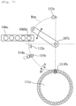
- Fig. 1 is an overall schematic diagram of an automatic analysis apparatus 100 according to a first embodiment.
- the automatic analysis apparatus 100 includes a control unit 102, an input unit 103, and a display unit 104.
- the control unit 102 is a computer in charge of the entire operation of the automatic analysis apparatus 100 including a specimen dispensing mechanism 107 described later.
- the input unit 103 is an input apparatus, for example, a keyboard and a mouse, for inputting various operation instructions and various data.
- the display unit 104 is, for example, a liquid crystal display, a printer, or the like and is a device that can display various analysis results, operating states of apparatuses, presence or absence of occurrence of abnormality, and the like.
- the automatic analysis apparatus 100 further includes a specimen vessel 105, a specimen vessel rack 106, the specimen dispensing mechanism 107, a reagent dispensing mechanism 108, a reagent vessel 109, a reaction vessel and dispensing tip accommodating unit 110, and an incubator 111.
- the specimen vessel 105 is a vessel that stores a specimen that is an object to be inspected.
- the specimen vessel rack 106 is a holding unit for holding the specimen vessel 105.
- the specimen vessel rack 106 is transported to a suction unit 106S described later by a transport mechanism not shown in the drawings.
- the specimen dispensing mechanism 107 is configured to be capable of holding a dispensing tip CP and sucking the specimen from the specimen vessel 105 and is also configured to be capable of discharging the sucked specimen to a reaction vessel RC.
- the reagent dispensing mechanism 108 is configured to be capable of sucking a reagent from the reagent vessel 109 and discharging the sucked reagent to the reaction vessel RC.
- the specimen dispensing mechanism 107 includes an arm 1071 that can rotate around a rotation shaft 1070 and a dispensing nozzle 1072 which is attached to a tip of the arm 1071 and configured to be capable of holding the dispensing tip CP.
- the reagent dispensing mechanism 108 also includes an arm that can rotate around a rotation shaft and a nozzle attached to a tip of the arm.
- the reaction vessel and dispensing tip accommodating unit 110 is an accommodating unit that accommodates the reaction vessels RC and the dispensing tips CP.
- the reaction vessel RC is appropriately transported to the incubator 111 by a transport mechanism not shown in the drawings.
- the dispensing tip CP is appropriately transported to mounting unit 114 described later by a transport mechanism not shown in the drawings and thereafter attached to the specimen dispensing mechanism 107 in the mounting unit 114.
- the incubator 111 has a temperature control mechanism and has a role to promote a reaction between the specimen and the reagent in the reaction vessel RC.
- the automatic analysis apparatus 100 further includes a sensor 112, a disposal unit 113, and a mounting unit 114.
- the sensor 112 is a detector for detecting whether or not the dispensing tip CP is attached to (removed from) the dispensing nozzle 1072 of the specimen dispensing mechanism 107 as described later.
- a method of the sensor 112 is not limited to a specific method, as an example, an optical sensor can be used as the sensor 112.
- the sensor 112 is not limited to an optical sensor, and a detection principle and the like of the sensor 112 do not matter as long as the sensor 112 can detect the presence of the dispensing tip CP.
- a transmission type photosensor or a reflection type photosensor can be employed as the optical sensor.
- the disposal unit 113 is a unit that removes a used dispensing tip CP from the specimen dispensing mechanism 107 and discards the dispensing tip CP after a specimen is injected into the reaction vessel RC.
- the mounting unit 114 is a mechanism for mounting an unused dispensing tip CP on the dispensing nozzle 1072 of the specimen dispensing mechanism 107.
- the mounting unit 114 can have a system where the dispensing tip CP is pressed against the dispensing nozzle 1072 and the dispensing tip CP is crimped to the dispensing nozzle 1072. However, the system does not matter as long as the dispensing tip CP is attached to the dispensing nozzle 1072.
- the specimen dispensing mechanism 107 includes the arm 1071 that can rotate around the rotation shaft 1070 and the dispensing nozzle 1072 that is attached to the arm 1071.
- the specimen dispensing mechanism 107 is configured to be capable of being moved along the arc-like movement path Rm by the rotation of the arm 1071.
- the movement path Rm is not limited to a curved line and may be a straight line.
- the curved line is not limited to an arc curve and may be, for example, an elliptic arc curve, a cycloidal curve, an asteroid curve, a spiral curve, or the like.
- the suction unit 106S in the specimen vessel rack 106, the disposal unit 113, a discharging unit 111P in the incubator 111, and the mounting unit 114 are arranged along the movement path Rm.
- the suction unit 106S, the disposal unit 113, a discharging unit 111P, and the mounting unit 114 are arranged along the movement path Rm, and thereby attachment, suction, discharge, and disposal operations of the dispensing tip CP are performed by the movement of the specimen dispensing mechanism 107 along the movement path Rm.
- a certain degree of freedom is allowed for the arrangement of the suction unit 106S, the disposal unit 113, a discharging unit 111P, the mounting unit 114, and the sensor 112 as described later.
- the sensor 112 is arranged so that the optical sensor 112 can detect the dispensing tip CP in a position between any two of the mounting unit 114, the suction unit 106S, the discharging unit 111P, and the disposal unit 113 in the movement path Rm.
- the detection position of the optical sensor 112 located in a position farther than an end portion (inside) of the movement path Rm when viewed from at least one of the mounting unit 114, the suction unit 106S, the discharging unit 111P, and the disposal unit 113.
- the detection position of the optical sensor 112 is arranged in the center of the movement path Rm, the discharging unit 111P and the mounting unit 114 are arranged on one side of the movement path Rm, and the disposal unit 113 and the suction unit 106S are arranged on the other side of the movement path Rm.
- the sensor 112 is arranged to be capable of detecting the dispensing tip CP in a position between the disposal unit 113 and the discharging unit 111P. This arrangement is particularly preferable from the viewpoint of minimizing useless movement of the specimen dispensing mechanism 107.
- a specimen dispensing operation is performed in the order described below.
- the mounting unit 114 and the discharging unit 111P are arranged on one side of the movement path Rm and the suction unit 106S and the disposal unit 113 are arranged on the other side of the movement path Rm.
- the detection position of the sensor 112 in any case of a movement from (A) to (B), a movement from (B) to (C), and a movement from (C) to (D), it is possible to pass through the detection position of the sensor 112 (without detouring the detection position of the sensor 112) during the movement. Therefore, it is possible to minimize the movement of the specimen dispensing mechanism 107 for detecting the presence or absence of the dispensing tip CP, and the throughput can be improved accordingly.
- the mounting unit 114 is arranged closer to (on a side closer to) the end portion of the movement path Rm than the suction unit 106S, the discharging unit 111P, and the disposal unit 113.
- the mounting unit 114 is a unit where an unused dispensing tip CP is arranged.
- the mounting unit 114 is located close to the end portion of the movement path Rm, so that in the operations of the above (A) to (D), the (used) dispensing tip CP that has sucked a specimen does not pass through above the mounting unit 114. Therefore, it is possible to avoid contamination of the unused dispensing tip CP arranged in the mounting unit 114.
- An initial position of the specimen dispensing mechanism 107 may be an arbitrary position. However, a position between the sensor 112 and the suction unit 106S is suitable for the initial position. Alternatively, a standby position where the specimen dispensing mechanism 107 (the dispensing nozzle 1072) stands by during a time other than a time of the specimen dispensing operation can be a position between the sensor 112 and the suction unit 106S in the same manner as the initial position.
- the dispensing nozzle 1072 of the specimen dispensing mechanism 107 starts moving from the initial position in a direction of an arrow A along the movement path Rm.
- the dispensing nozzle 1072 of the specimen dispensing mechanism 107 reaches the mounting unit 114 and is mounted with the dispensing tip CP (step S1).
- the dispensing nozzle 1072 moves in the opposite direction (direction of an arrow B) on the movement path Rm, passes through the discharging unit 111P, the detection position of the sensor 112, and the disposal unit 113, reaches the suction unit 106S, and sucks a specimen from the specimen vessel 105 in the suction unit 106S (step S3).
- the sensor 112 detects the presence or absence of mounting of the dispensing tip CP at the tip of the dispensing nozzle 1072 (step S2).
- the dispensing tip CP When the mounting of the dispensing tip CP is detected, it is determined that the dispensing operation is normally performed, and the dispensing operation is continued. When the dispensing tip CP is not detected, it is determined that an abnormality occurs in the dispensing operation (the mounting of the dispensing tip CP fails), the operation of the specimen dispensing mechanism 107 is stopped, and an abnormality notification is displayed on the display unit 104.
- the specimen dispensing mechanism 107 After sucking the specimen in the suction unit 106S, the specimen dispensing mechanism 107 returns again on the movement path Rm in the opposite direction (the direction of the arrow A), passes through the disposal unit 113 and the detection position of the sensor 112, and reaches the discharging unit 111P of the incubator 111. In the discharging unit 111P, the specimen dispensing mechanism 107 discharges the specimen into the reaction vessel RC (step S5). During a transitional period from step S3 to step S5, when the dispensing nozzle 1072 passes through the detection position of the sensor 112, the presence or absence of mounting of the dispensing tip CP at the tip of the dispensing nozzle 1072 is detected (step S4).
- the dispensing tip CP When the mounting of the dispensing tip CP is detected, it is determined that the dispensing operation is normally performed, and the dispensing operation is continued. When the dispensing tip CP is not detected, it is determined that an abnormality occurs in the dispensing operation, the operation of the specimen dispensing mechanism 107 is stopped, and an abnormality notification is displayed on the display unit 104.
- the dispensing nozzle 1072 of the specimen dispensing mechanism 107 moves again on the movement path Rm in the direction of the arrow B, passes through the sensor 112, and then reaches the disposal unit 113.
- the dispensing tip CP is removed from the dispensing nozzle 1072 and the dispensing tip CP is discarded (step S7).
- step S6 the presence or absence of mounting of the dispensing tip CP at the tip of the dispensing nozzle 1072 is detected.
- the dispensing tip CP When the mounting of the dispensing tip CP is detected, it is determined that the dispensing operation is normally performed, and the dispensing operation is continued. When the dispensing tip CP is not detected, it is determined that an abnormality occurs in the dispensing operation, the operation of the specimen dispensing mechanism 107 is stopped, and an abnormality notification is displayed on the display unit 104.
- the specimen dispensing mechanism 107 When the disposal of the dispensing tip CP in the disposal unit 113 is completed, the specimen dispensing mechanism 107 returns to the standby position described above and stands by until the next dispensing instruction is received. Before transiting to this standby state, the specimen dispensing mechanism 107 passes through the detection position of the sensor 112, so that the sensor 112 detects the presence or absence of the dispensing tip CP at the tip of the dispensing nozzle 1072. When it is determined that the dispensing tip CP is absent, it is determined that the disposal of the dispensing tip CP is completed, and the dispensing operation is continued.
- the specimen dispensing mechanism 107 moves the dispensing nozzle 1072 from the standby position to the mounting unit 114 through the sensor 112 and the discharging unit 111P.
- the same procedure as described above will be repeated.
- the mounting unit 114, the suction unit 106S, the discharging unit 111P, and the disposal unit 113 are arranged as described above, so that the specimen dispensing mechanism 107 can pass through the detection position of the sensor 112 without detouring the detection position of the sensor 112 during a transition between steps S1, S3, S5, and S7 described above. Therefore, it is possible to improve the throughput of the automatic analysis apparatus.
- the sensor 112 is provided outside the specimen dispensing mechanism 107, and only one sensor 112 is provided, so that it is possible to reduce the cost.
- the sensor 112 When the dispensing nozzle 1072 passes through the sensor 112, if the sensor 112 cannot detect the dispensing tip CP even when the dispensing tip CP should have been mounted on the dispensing nozzle 1072 or if the sensor 112 detects mounting of the dispensing tip CP even when the dispensing tip CP should not have been mounted on the dispensing nozzle 1072, It is possible to determine that an abnormality occurs, cause the display unit 104 to notify occurrence of abnormality, and stop the specimen dispensing operation.
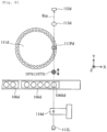
- Fig. 4 is a schematic diagram showing an arrangement of a discharging unit 111Pa, a disposal unit 113a, a suction unit 106Sa, a mounting unit 114a, and a sensor 112a in the automatic analysis apparatus 100 according to the second embodiment.
- the entire configuration of the apparatus is substantially the same as that in Fig. 1 except for the arrangement of the discharging unit 111Pa, the disposal unit 113a, the suction unit 106Sa, the mounting unit 114a, and the sensor 112a, so that redundant description will be omitted.
- Fig. 1 the entire configuration of the apparatus is substantially the same as that in Fig. 1 except for the arrangement of the discharging unit 111Pa, the disposal unit 113a, the suction unit 106Sa, the mounting unit 114a, and the sensor 112a, so that redundant description will be omitted.
- the discharging unit 111Pa, the disposal unit 113a, the suction unit 106Sa, the mounting unit 114a, and the sensor 112a respectively correspond to the discharging unit 111P, the disposal unit 113, the suction unit 106S, the mounting unit 114, and the sensor 112 of the first embodiment ( Fig. 2 ), so that redundant description will be omitted.
- the detection position of the optical sensor 112a is arranged in the center of the movement path Rm, and this is the same as in the first embodiment ( Fig. 2 ).
- the discharging unit 111Pa and the mounting unit 114a are arranged on one side of the movement path Rm, and the disposal unit 113a and the suction unit 106Sa are arranged on the other side of the movement path Rm.
- the positional relationship between the disposal unit 113a and the suction unit 106Sa is reverse to that in Fig. 2 .
- the disposal unit 113a is arranged close to an end portion of the movement path Rm, and the suction unit 106Sa is arranged more inside of the movement path Rm than the disposal unit 113a. Also in the arrangement of Fig. 4 , when the specimen dispensing operation ( Fig. 3 ) is performed, it is possible to eliminate useless movement of the specimen dispensing mechanism 107 and improve the throughput of the automatic analysis apparatus in the same manner as in Fig. 2 (the first embodiment).
- the details of the specimen dispensing operation in the second embodiment are substantially the same as that in the first embodiment, so that redundant description will be omitted.
- a moving distance of the specimen dispensing mechanism 107 when transiting from step S1 to step S3 in the second embodiment is shorter than that in the first embodiment.
- a moving distance of the specimen dispensing mechanism 107 when transiting from step S5 to step S7 in the second embodiment is longer than that in the first embodiment.
- the throughput of the apparatus of the second embodiment is substantially the same as that of the first embodiment.
- FIG. 5 is a schematic diagram showing an arrangement of a discharging unit 111Pb, a disposal unit 113b, a suction unit 106Sb, a mounting unit 114b, and a sensor 112b in the automatic analysis apparatus 100 according to the third embodiment.
- the entire configuration of the apparatus is substantially the same as that in Fig. 1 except for the arrangement of the discharging unit 111Pb, the disposal unit 113b, the suction unit 106Sb, the mounting unit 114b, and the sensor 112b, so that redundant description will be omitted.
- Fig. 1 is a schematic diagram showing an arrangement of a discharging unit 111Pb, a disposal unit 113b, a suction unit 106Sb, a mounting unit 114b, and a sensor 112b in the automatic analysis apparatus 100 according to the third embodiment.
- the entire configuration of the apparatus is substantially the same as that in Fig. 1 except for the arrangement of the discharging unit 111Pb, the disposal unit 113b,
- the discharging unit 111Pb, the disposal unit 113b, the suction unit 106Sb, the mounting unit 114b, and the sensor 112b respectively correspond to the discharging unit 111P, the disposal unit 113, the suction unit 106S, the mounting unit 114, and the sensor 112 of the first embodiment ( Fig. 2 ), so that redundant description will be omitted.
- the detection position of the optical sensor 112b is arranged in the center of the movement path Rm, and this is the same as in the first and second embodiments ( Figs. 2 and 4 ).
- the discharging unit 111Pb and the mounting unit 114b are arranged on one side of the movement path Rm, and the disposal unit 113b and the suction unit 106Sb are arranged on the other side of the movement path Rm. This is also the same as in the first embodiment.
- the positional relationship between the mounting unit 114b and the discharging unit 111Pb is reverse to that in Figs. 2 and 4 .
- the mounting unit 114b is arranged in a position farther from an end portion of the movement path Rm than the discharging unit 111Pb, and this is different from the examples in Figs. 2 and 4 .
- the dispensing tip CP that has sucked a specimen can pass through above the mounting unit 114b in the middle of the specimen dispensing operation. In this case, it can be considered that an unused dispensing tip CP mounted in the mounting unit 114b is contaminated by the specimen and an accurate inspection is hindered.
- this problem is solved by separately providing a mounting unit cover 115b that covers the mounting unit 114b. As described later, during a mounting operation, the mounting unit cover 115b is retreated from the mounting unit 114b, and otherwise, the mounting unit cover 115b is arranged so as to cover the mounting unit 114b.
- the mounting unit cover 115b includes a rotation shaft 1151 and a shielding plate 1152 that rotates around the rotation shaft 1151.
- the rotation shaft 1151 is arranged close to the mounting unit 114b and is configured to be able to be rotated by a motor not shown in the drawings.
- the shielding plate 1152 is set to a shielding position (solid line in Fig. 6 ) that covers the mounting unit 114b or a retreat position (dashed line in Fig. 6 ) that does not cover the mounting unit 114b by the rotation of the rotation shaft 1151.
- a used dispensing tip CPo after the specimen dispensing mechanism 107b sucks a specimen is held at the tip of the dispensing nozzle 1072, and when such a used dispensing tip CPo passes through above the mounting unit 114b, the shielding plate 1152 is set to the shielding position described above. Thereby, it is possible to prevent the specimen from leaking and falling from the used dispensing tip CPo to the mounting unit 114b and to prevent an unused dispensing tip CPn from being contaminated.
- the mounting unit cover 115b has a structure that rotates around the rotation shaft, however, it is not limited thereto and the shielding plate 1152 may be slid by being driven by a solenoid or the like.
- the specimen dispensing operation in the automatic analysis apparatus in Fig. 5 will be described in detail with reference to the flowchart in Fig. 3 .
- the specimen dispensing mechanism 107b is located in the initial position or the standby position between the disposal unit 113b and the suction unit 106Sb and the next specimen dispensing instruction is waited.
- the dispensing nozzle 1072 of the specimen dispensing mechanism 107b starts moving from the initial position or the standby position in a direction of an arrow A along the movement path Rm.
- the mounting unit cover 115b receives the specimen dispensing instruction and moves to the retreat position. Instead that the mounting unit cover 115b receives the specimen dispensing instruction and moves to the retreat position, it is possible to define that when the specimen dispensing mechanism 107b is located in the initial position or the standby position, the specimen dispensing mechanism 107b has been moved to the retreat position.
- step S1 When the dispensing nozzle 1072 of the specimen dispensing mechanism 107b reaches the mounting unit 114b, and the dispensing tip CP is mounted on the dispensing nozzle 1072 (step S1).
- the dispensing nozzle 1072 moves in the opposite direction (direction of an arrow B) on the movement path Rm, passes through the detection position of the sensor 112b and the disposal unit 113b, reaches the suction unit 106Sb, and sucks a specimen from the specimen vessel 105 in the suction unit 106Sb (step S3).
- the sensor 112b detects the presence or absence of mounting of the dispensing tip CP at the tip of the dispensing nozzle 1072 (step S2).
- the dispensing tip CP When the mounting of the dispensing tip CP is detected, it is determined that the dispensing operation is normally performed, and the dispensing operation is continued. When the dispensing tip CP is not detected, it is determined that an abnormality occurs in the dispensing operation, the operation of the specimen dispensing mechanism 107b is stopped, and an abnormality notification is displayed on the display unit 104.
- step S1 the mounting unit cover 115b moves to the shielding position described above at any timing until a time point when the specimen dispensing mechanism 107b passes through the mounting unit 114b.
- the specimen dispensing mechanism 107b After sucking the specimen in the suction unit 106Sb, the specimen dispensing mechanism 107b returns again on the movement path Rm in the opposite direction (the direction of the arrow A), passes through the disposal unit 113b, the detection position of the sensor 112b, and above the mounting unit 114b shielded by the mounting unit cover 115b, and reaches the discharging unit 111Pb of the incubator 111b.
- the used dispensing tip CPo passes through above the mounting unit 114b, the mounting unit 114b is shielded by the mounting unit cover 115b. Therefore, the unused dispensing tip CPn is prevented from being contaminated.
- the specimen dispensing mechanism 107b discharges the specimen into the reaction vessel RC (step S5).
- the dispensing nozzle 1072 passes through the detection position of the sensor 112b, the presence or absence of mounting of the dispensing tip CP at the tip of the dispensing nozzle 1072 is detected (step S4).
- the mounting of the dispensing tip CP is detected, it is determined that the dispensing operation is normally performed, and the dispensing operation is continued.
- the dispensing tip CP is not detected, it is determined that an abnormality occurs in the dispensing operation, the operation of the specimen dispensing mechanism 107b is stopped, and an abnormality notification is displayed on the display unit 104.
- the dispensing nozzle 1072 of the specimen dispensing mechanism 107b moves again on the movement path Rm in the direction of the arrow B, passes through the mounting unit 114b and the sensor 112b, and then reaches the disposal unit 113b. Also in this stage, it is preferable that the mounting unit 114b is covered by the mounting unit cover 115b. In the disposal unit 113b, the dispensing tip CP is removed from the dispensing nozzle 1072 and the dispensing tip CP is discarded (step S7).
- step S6 when the dispensing nozzle 1072 passes through the detection position of the sensor 112b, the presence or absence of mounting of the dispensing tip CP at the tip of the dispensing nozzle 1072 is detected (step S6).
- the mounting of the dispensing tip CP it is determined that the dispensing operation is normally performed, and the dispensing operation is continued.
- the dispensing tip CP is not detected, it is determined that an abnormality occurs in the dispensing operation, the operation of the specimen dispensing mechanism 107b is stopped, and an abnormality notification is displayed on the display unit 104.
- the operation after the dispensing tip CP has been discarded in the disposal unit 113b is substantially the same as that in the embodiments described above.
- the same effect as that of the embodiments described above can be obtained.
- the mounting unit 114b is located in the middle of the movement path Rm, it is possible to avoid contamination of the mounting unit 114b because the mounting unit cover 115b is provided.
- Fig. 7 is a schematic diagram showing an arrangement of a discharging unit 111Pc, a disposal unit 113c, a suction unit 106Sc, a mounting unit 114c, and a sensor 112c in the automatic analysis apparatus 100 according to the fourth embodiment.
- the entire configuration of the apparatus is substantially the same as that in Fig. 1 except for the arrangement of the discharging unit 111Pc, the disposal unit 113c, the suction unit 106Sc, the mounting unit 114c, and the sensor 112c, so that redundant description will be omitted.
- Fig. 1 is a schematic diagram showing an arrangement of a discharging unit 111Pc, a disposal unit 113c, a suction unit 106Sc, a mounting unit 114c, and a sensor 112c in the automatic analysis apparatus 100 according to the fourth embodiment.
- the entire configuration of the apparatus is substantially the same as that in Fig. 1 except for the arrangement of the discharging unit 111Pc, the disposal unit 113c
- the discharging unit 111Pc, the disposal unit 113c, the suction unit 106Sc, the mounting unit 114c, and the sensor 112c respectively correspond to the discharging unit 111P, the disposal unit 113, the suction unit 106S, the mounting unit 114, and the sensor 112 of the first embodiment ( Fig. 2 ), so that redundant description will be omitted.
- the detection position of the optical sensor 112c is arranged in the center of the movement path Rm, and this is the same as in the first to the third embodiments.
- the discharging unit 111Pc and the mounting unit 114c are arranged on one side of the movement path Rm, and the disposal unit 113c and the suction unit 106Sc are arranged on the other side of the movement path Rm. This is also the same as in the first to the third embodiments.
- the mounting unit 114b in the same manner as in the third embodiment ( Fig. 5 ), is arranged in a position farther from an end portion of the movement path Rm than the discharging unit 111Pb. Therefore, a mounting unit cover 115c that covers the mounting unit 114c is provided.
- the mounting unit cover 115c may be the same as the mounting unit cover 115b of the third embodiment.
- the disposal unit 113c is arranged at an end portion of the movement path Rm, and the suction unit 106Sc is arranged inside of the movement path Rm.
- the same effect as that of the embodiments described above can be obtained.
- the mounting unit 114c is located in the middle of the movement path Rm in the same manner as in the third embodiment, it is possible to avoid contamination of the unused dispensing tip CPn of the mounting unit 114c because the mounting unit cover 115c is provided.
- the senor is located at the center of the movement path Rm, the mounting unit (114 to 114c) and the discharging unit (111P to 111Pc) are located on one side of the movement path Rm, and the suction unit (106S to 106Sc) and the disposal unit (113 to 113c) are located on the other side of the movement path Rm.
- the configurations of these embodiments can minimize useless movement of the specimen dispensing mechanism.
- the present invention is not limited to the first to the fourth embodiments.
- the arrangement of the mounting unit, the suction unit, the discharging unit, the disposal unit, and the sensor can be variously changed.
- Fig. 8 is a schematic diagram showing an arrangement of a discharging unit 111Pd, a disposal unit 113d, a suction unit 106Sd, a mounting unit 114d, and a sensor 112d in the automatic analysis apparatus 100 according to the fifth embodiment.
- the entire configuration of the apparatus is substantially the same as that in Fig. 1 except for the arrangement of the discharging unit 111Pd, the disposal unit 113d, the suction unit 106Sd, the mounting unit 114d, and the sensor 112d, so that redundant description will be omitted.
- Figs. 1 the arrangement of the discharging unit 111Pd, the disposal unit 113d, the suction unit 106Sd, the mounting unit 114d, and the sensor 112d, so that redundant description will be omitted.
- the discharging unit 111Pd, the disposal unit 113d, the suction unit 106Sd, the mounting unit 114d, and the sensor 112d respectively correspond to the discharging unit 111P, the disposal unit 113, the suction unit 106S, the mounting unit 114, and the sensor 112 of the first embodiment ( Fig. 2 ), so that redundant description will be omitted.
- the fifth embodiment is different from the embodiments described above.
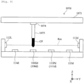
- the discharging unit 111Pd, the disposal unit 113d, the suction unit 106Sd, and the mounting unit 114d are arranged along a straight line, and a specimen dispensing mechanism 107d moves a dispensing nozzle 1075 along the straight line.
- a specimen dispensing mechanism 107d moves a dispensing nozzle 1075 along the straight line.
- the dispensing nozzle 1075 can be attached to one end of the block 1074.
- the dispensing nozzle 1075 can move along the straight-line movement path Rm. This is different from the embodiments described above where the dispensing nozzle is arcuately moved.
- the automatic analysis apparatus of the fifth embodiment is provided with the sensor 112d that detects the presence or absence of mounting of the dispensing tip CP on the dispensing nozzle 1075 that moves lineally.
- the sensor 112d includes a laser light source 112L that emits laser light along the movement path Rm and an optical sensor 112d arranged on an extended line of the movement path Rm. The laser light from the laser light source 112L is blocked when the dispensing tip CP is attached to the dispensing nozzle 1075. Thereby, the optical sensor 112d can detect the presence or absence of the mounting of the dispensing tip CP.
- the sensor 112d may be an image sensor arranged on the extended line of the movement path Rm instead of the laser light source and the optical sensor as shown in Figs. 8 and 9 .
- the operation of the fifth embodiment can be performed similarly to the operations of the embodiments described above, so that its description is omitted here.
- An arrangement order of the discharging unit 111Pd, the disposal unit 113d, the suction unit 106Sd, and the mounting unit 114d can be arbitrarily changed.
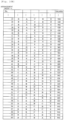
- Figs. 10A and 10B is a diagram illustrating combinations of the arrangement orders of the mounting unit 114, the suction unit 106S, the discharging unit 111P, the disposal unit 113, and the sensor 112 in the first to the fourth embodiments, and their evaluations (SP (superb) (best), EX (excellent) (better), GD (good) (good), or NG (no good) (poor)).
- SP superb
- EX excellent
- GD good
- NG no good
- No.1 shows an arrangement in which the mounting unit, the suction unit, the discharging unit, the disposal unit, and the sensor are arranged in this order from an end portion of the movement path.
- No. 12 No. 11, No. 38, and No. 46 represent the first embodiment, the second embodiment, the third embodiment, and the fourth embodiment, respectively. These can minimize useless movement of the specimen dispensing mechanism, so that their evaluations are SP (best) or EX (better).
- the first and the second embodiments are preferable in particular because the mounting unit cover is not required in these embodiments.
- the specimen dispensing mechanism has to move (detour) to the sensor once or twice.
- sufficiently high throughput can be obtained, so that the arrangements are determined to be GD (good).
Landscapes
- Physics & Mathematics (AREA)
- Health & Medical Sciences (AREA)
- Life Sciences & Earth Sciences (AREA)
- Chemical & Material Sciences (AREA)
- Analytical Chemistry (AREA)
- Biochemistry (AREA)
- General Health & Medical Sciences (AREA)
- General Physics & Mathematics (AREA)
- Immunology (AREA)
- Pathology (AREA)
- Automatic Analysis And Handling Materials Therefor (AREA)
Abstract
Description
- The present invention relates to an automatic analysis apparatus.
- In recent years, an automatic analysis apparatus is increasingly required to provide high processing performance and accurate analysis results. In order to obtain high processing performance, it is necessary to reduce useless operations as much as possible in the automatic analysis apparatus. An automatic analysis apparatus is known which is configured to perform dispensing of a specimen or a reagent by using a disposable dispensing tip in order to prevent abnormality of an analysis result due to contamination of a biological sample or a regent.
- The disposable dispensing tip is attached to a dispensing mechanism for each dispensing operation, and is removed from the dispensing mechanism for disposal. Therefore, there is concern over a failure of attaching and/or removing the dispensing tip and a falling of the dispensing tip during the dispensing operation. When an attaching failure occurs, a normal dispensing operation cannot be performed, and when a removing failure occurs, it causes abnormal dispensing and the like due to double mounting of dispensing tips. Further, when the dispensing tip falls, a normal dispensing operation cannot be performed.
- Therefore, for example,
Patent Literature 1 proposes an automatic analysis apparatus having a configuration that confirms whether or not the dispensing tip is mounted to the dispensing mechanism during the dispensing operation.Patent Literature 1 discloses a configuration in which the dispensing tip is mounted to the dispensing mechanism and a microswitch that is an accessory of the dispensing mechanism detects whether or not the dispensing tip is mounted. - However, when a sensor, a switch, or the like is provided to the dispensing mechanism itself, the structure of the dispensing mechanism is complicated and there is concern over increase of cost, so that this is not preferable. When a sensor is provided outside the dispensing mechanism, the cost of the dispensing mechanism is suppressed. However, when there is only one sensor, the dispensing mechanism is required to move to a sensor position many times for confirming the presence or absence of mounting of the dispensing tip, so that processing performance is affected and the throughput is degraded. When a plurality of sensors are provided, useless movement to the sensor position is not required. However, this is not preferable in cost.
- Patent Literature 1:
Japanese Patent No. 3177608 - An object of the present invention is to provide a low-cost and high-throughput automatic analysis apparatus.
- To solve the above problem, an automatic analysis apparatus according to a first aspect of the present invention includes an incubator which accommodates a plurality of reaction vessels, a specimen dispensing mechanism which dispenses a specimen into each of the plurality of reaction vessels, a mounting unit which mounts a dispensing tip on the specimen dispensing mechanism, a suction unit which sucks a specimen from a specimen vessel containing the specimen by means of the specimen dispensing mechanism having the dispensing tip mounted thereon, a discharging unit which is provided in the incubator and discharges the specimen from the specimen dispensing mechanism to the reaction vessel, a disposal unit which discards the dispensing tip, a sensor which detects whether the dispensing tip is mounted to the specimen dispensing mechanism, and a control unit which controls the specimen dispensing mechanism. The mounting unit, the suction unit, the discharging unit, and the disposal unit are arranged along a movement path of the specimen dispensing mechanism. The sensor is arranged so as to be able to detect the dispensing tip at a position sandwiched between any two of the mounting unit, the suction unit, the discharging unit, and the disposal unit.
- An automatic analysis apparatus according to a second aspect of the present invention includes an incubator which accommodates a plurality of reaction vessels, a specimen dispensing mechanism which dispenses a specimen into each of the plurality of reaction vessels, a mounting unit which mounts a dispensing tip on the specimen dispensing mechanism, a suction unit which sucks a specimen from a specimen vessel containing the specimen by means of the specimen dispensing mechanism having the dispensing tip mounted thereon, a discharging unit which is provided in the incubator and discharges the specimen from the specimen dispensing mechanism to the reaction vessel, a disposal unit which discards the dispensing tip, a sensor which detects whether the dispensing tip is mounted to the specimen dispensing mechanism, and a control unit which controls the specimen dispensing mechanism. The mounting unit, the suction unit, the discharging unit, and the disposal unit are arranged along a straight line. The specimen dispensing mechanism is configured to be capable of moving the dispensing tip along the straight line. The sensor is configured to be capable of detecting whether there is the dispensing tip on the straight line or not.
- According to the present invention, it is possible to provide a low-cost and high-throughput automatic analysis apparatus.
-
- [
Fig. 1] Fig. 1 is an overall schematic diagram of anautomatic analysis apparatus 100 according to a first embodiment. - [
Fig. 2] Fig. 2 is a view illustrating a positional relationship between a movement path Rm of aspecimen dispensing mechanism 107 and other constituent elements according to the first embodiment. - [
Fig. 3] Fig. 3 is a flowchart illustrating an operation of theautomatic analysis apparatus 100 according to the first embodiment. - [
Fig. 4] Fig. 4 is a view illustrating a positional relationship between a movement path Rm of aspecimen dispensing mechanism 107a and other constituent elements according to a second embodiment. - [
Fig. 5] Fig. 5 is a view illustrating a positional relationship between a movement path Rm of aspecimen dispensing mechanism 107b and other constituent elements according to a third embodiment. - [
Fig. 6] Fig. 6 is a schematic cross-sectional view illustrating a structure and an operation of amounting unit cover 115b according to the third embodiment. - [
Fig. 7] Fig. 7 is a view illustrating a positional relationship between a movement path Rm of aspecimen dispensing mechanism 107c and other constituent elements according to a fourth embodiment. - [
Fig. 8] Fig. 8 is a schematic plan view showing an arrangement of a discharging unit 111Pd, adisposal unit 113d, a suction unit 106Sd, amounting unit 114d, and asensor 112d according to a fifth embodiment. - [
Fig. 9] Fig. 9 is a schematic cross-sectional view along a movement path Rm according to the fifth embodiment. - [
Fig. 10A] Fig.10A is a diagram illustrating combinations each of which shows an arrangement order of amounting unit 114, asuction unit 106S, adischarging unit 111P, adisposal unit 113, and asensor 112, and evaluations thereof according to the first to fourth embodiments. - [
Fig. 10B] Fig. 10B is a diagram illustrating combinations each of which shows an arrangement order of themounting unit 114, thesuction unit 106S, thedischarging unit 111P, thedisposal unit 113, and thesensor 112, and evaluations thereof according to the first to fourth embodiments. - Hereinafter, embodiments will be described with reference to the accompanying drawings. In the accompanying drawings, elements having the same functions may be represented by the same numbers or corresponding numbers. Although the accompanying drawings show embodiments and implementation examples based on the principle of the present disclosure, these are to understand the present disclosure and are never used to restrictively interpret the present disclosure. The description of the present specification is only a typical example and does not limit in any sense the claims or application examples of the present disclosure.
- The embodiments are sufficiently described in detail so that a person skilled in the art can carry out the present disclosure. However, other implementations and forms are possible, and it is necessary to understand that change of configurations/structures and replacement of various elements are possible without departing from the scope and spirit of the technical idea of the present disclosure. Therefore, the description below shall not be construed to be limited to the embodiments.
-
Fig. 1 is an overall schematic diagram of anautomatic analysis apparatus 100 according to a first embodiment. Theautomatic analysis apparatus 100 includes acontrol unit 102, aninput unit 103, and adisplay unit 104. Thecontrol unit 102 is a computer in charge of the entire operation of theautomatic analysis apparatus 100 including aspecimen dispensing mechanism 107 described later. Theinput unit 103 is an input apparatus, for example, a keyboard and a mouse, for inputting various operation instructions and various data. Thedisplay unit 104 is, for example, a liquid crystal display, a printer, or the like and is a device that can display various analysis results, operating states of apparatuses, presence or absence of occurrence of abnormality, and the like. - The
automatic analysis apparatus 100 further includes aspecimen vessel 105, aspecimen vessel rack 106, thespecimen dispensing mechanism 107, areagent dispensing mechanism 108, areagent vessel 109, a reaction vessel and dispensingtip accommodating unit 110, and anincubator 111. Thespecimen vessel 105 is a vessel that stores a specimen that is an object to be inspected. Thespecimen vessel rack 106 is a holding unit for holding thespecimen vessel 105. Thespecimen vessel rack 106 is transported to asuction unit 106S described later by a transport mechanism not shown in the drawings. - The
specimen dispensing mechanism 107 is configured to be capable of holding a dispensing tip CP and sucking the specimen from thespecimen vessel 105 and is also configured to be capable of discharging the sucked specimen to a reaction vessel RC. Thereagent dispensing mechanism 108 is configured to be capable of sucking a reagent from thereagent vessel 109 and discharging the sucked reagent to the reaction vessel RC. As shown in the lower right ofFig. 1 separated from the overall schematic diagram, thespecimen dispensing mechanism 107 includes anarm 1071 that can rotate around arotation shaft 1070 and a dispensingnozzle 1072 which is attached to a tip of thearm 1071 and configured to be capable of holding the dispensing tip CP. Although not shown in the drawings, thereagent dispensing mechanism 108 also includes an arm that can rotate around a rotation shaft and a nozzle attached to a tip of the arm. - The reaction vessel and dispensing
tip accommodating unit 110 is an accommodating unit that accommodates the reaction vessels RC and the dispensing tips CP. The reaction vessel RC is appropriately transported to theincubator 111 by a transport mechanism not shown in the drawings. The dispensing tip CP is appropriately transported to mountingunit 114 described later by a transport mechanism not shown in the drawings and thereafter attached to thespecimen dispensing mechanism 107 in the mountingunit 114. Theincubator 111 has a temperature control mechanism and has a role to promote a reaction between the specimen and the reagent in the reaction vessel RC. - The
automatic analysis apparatus 100 further includes asensor 112, adisposal unit 113, and a mountingunit 114. Thesensor 112 is a detector for detecting whether or not the dispensing tip CP is attached to (removed from) thedispensing nozzle 1072 of thespecimen dispensing mechanism 107 as described later. Although a method of thesensor 112 is not limited to a specific method, as an example, an optical sensor can be used as thesensor 112. However, thesensor 112 is not limited to an optical sensor, and a detection principle and the like of thesensor 112 do not matter as long as thesensor 112 can detect the presence of the dispensing tip CP. As an example, a transmission type photosensor or a reflection type photosensor can be employed as the optical sensor. - The
disposal unit 113 is a unit that removes a used dispensing tip CP from thespecimen dispensing mechanism 107 and discards the dispensing tip CP after a specimen is injected into the reaction vessel RC. The mountingunit 114 is a mechanism for mounting an unused dispensing tip CP on the dispensingnozzle 1072 of thespecimen dispensing mechanism 107. The mountingunit 114 can have a system where the dispensing tip CP is pressed against the dispensingnozzle 1072 and the dispensing tip CP is crimped to the dispensingnozzle 1072. However, the system does not matter as long as the dispensing tip CP is attached to the dispensingnozzle 1072. - Next, a positional relationship between a movement path Rm of the
specimen dispensing mechanism 107 and other constituent elements will be described with reference toFig. 2 . - As described above, the
specimen dispensing mechanism 107 includes thearm 1071 that can rotate around therotation shaft 1070 and the dispensingnozzle 1072 that is attached to thearm 1071. Thespecimen dispensing mechanism 107 is configured to be capable of being moved along the arc-like movement path Rm by the rotation of thearm 1071. The movement path Rm is not limited to a curved line and may be a straight line. The curved line is not limited to an arc curve and may be, for example, an elliptic arc curve, a cycloidal curve, an asteroid curve, a spiral curve, or the like. - The
suction unit 106S in thespecimen vessel rack 106, thedisposal unit 113, a dischargingunit 111P in theincubator 111, and the mountingunit 114 are arranged along the movement path Rm. Thesuction unit 106S, thedisposal unit 113, a dischargingunit 111P, and the mountingunit 114 are arranged along the movement path Rm, and thereby attachment, suction, discharge, and disposal operations of the dispensing tip CP are performed by the movement of thespecimen dispensing mechanism 107 along the movement path Rm. - A certain degree of freedom is allowed for the arrangement of the
suction unit 106S, thedisposal unit 113, a dischargingunit 111P, the mountingunit 114, and thesensor 112 as described later. However, thesensor 112 is arranged so that theoptical sensor 112 can detect the dispensing tip CP in a position between any two of the mountingunit 114, thesuction unit 106S, the dischargingunit 111P, and thedisposal unit 113 in the movement path Rm. In other words, the detection position of theoptical sensor 112 located in a position farther than an end portion (inside) of the movement path Rm when viewed from at least one of the mountingunit 114, thesuction unit 106S, the dischargingunit 111P, and thedisposal unit 113. By employing such an arrangement, it is possible to eliminate useless movement of thespecimen dispensing mechanism 107, and as a result, the throughput of the automatic analysis apparatus can be improved. - In the example in
Fig. 2 , the detection position of theoptical sensor 112 is arranged in the center of the movement path Rm, the dischargingunit 111P and the mountingunit 114 are arranged on one side of the movement path Rm, and thedisposal unit 113 and thesuction unit 106S are arranged on the other side of the movement path Rm. In other words, thesensor 112 is arranged to be capable of detecting the dispensing tip CP in a position between thedisposal unit 113 and the dischargingunit 111P. This arrangement is particularly preferable from the viewpoint of minimizing useless movement of thespecimen dispensing mechanism 107. As shown in the flowchart inFig. 3 , a specimen dispensing operation is performed in the order described below. - (A) Mounting of the dispensing tip CP in the mounting unit 114 (step S1)
- (B) Suction of specimen in the
suction unit 106S (step S3) - (C) Discharge of specimen in the discharging
unit 111P (step S5) - (D) Disposal of specimen in the disposal unit 113 (step S7)
- In the arrangement of
Fig. 2 , when viewed from the detection position of thesensor 112, the mountingunit 114 and the dischargingunit 111P are arranged on one side of the movement path Rm and thesuction unit 106S and thedisposal unit 113 are arranged on the other side of the movement path Rm. In the case of this arrangement, in any case of a movement from (A) to (B), a movement from (B) to (C), and a movement from (C) to (D), it is possible to pass through the detection position of the sensor 112 (without detouring the detection position of the sensor 112) during the movement. Therefore, it is possible to minimize the movement of thespecimen dispensing mechanism 107 for detecting the presence or absence of the dispensing tip CP, and the throughput can be improved accordingly. - Further, in the example in
Fig. 2 , the mountingunit 114 is arranged closer to (on a side closer to) the end portion of the movement path Rm than thesuction unit 106S, the dischargingunit 111P, and thedisposal unit 113. As described above, the mountingunit 114 is a unit where an unused dispensing tip CP is arranged. The mountingunit 114 is located close to the end portion of the movement path Rm, so that in the operations of the above (A) to (D), the (used) dispensing tip CP that has sucked a specimen does not pass through above the mountingunit 114. Therefore, it is possible to avoid contamination of the unused dispensing tip CP arranged in the mountingunit 114. - An initial position of the specimen dispensing mechanism 107 (the dispensing nozzle 1072) may be an arbitrary position. However, a position between the
sensor 112 and thesuction unit 106S is suitable for the initial position. Alternatively, a standby position where the specimen dispensing mechanism 107 (the dispensing nozzle 1072) stands by during a time other than a time of the specimen dispensing operation can be a position between thesensor 112 and thesuction unit 106S in the same manner as the initial position. By doing so, it is possible to detect the presence or absence of mounting of the dispensing tip CP on the dispensingnozzle 1072 before the dispensingnozzle 1072 moves from the initial position to the mountingunit 114 and the dispensing tip CP is mounted on the dispensingnozzle 1072. - Next, the specimen dispensing operation in the automatic analysis apparatus in
Fig. 2 according to the flowchart inFig. 3 will be described in detail. - When a specimen dispensing instruction is inputted from the
input unit 103 or the like through thecontrol unit 102, by a control signal from thecontrol unit 102, the dispensingnozzle 1072 of thespecimen dispensing mechanism 107 starts moving from the initial position in a direction of an arrow A along the movement path Rm. The dispensingnozzle 1072 of thespecimen dispensing mechanism 107 reaches the mountingunit 114 and is mounted with the dispensing tip CP (step S1). - Thereafter, the dispensing
nozzle 1072 moves in the opposite direction (direction of an arrow B) on the movement path Rm, passes through the dischargingunit 111P, the detection position of thesensor 112, and thedisposal unit 113, reaches thesuction unit 106S, and sucks a specimen from thespecimen vessel 105 in thesuction unit 106S (step S3). During a transitional period from step S1 to step S3, when the dispensingnozzle 1072 passes through the detection position of thesensor 112, thesensor 112 detects the presence or absence of mounting of the dispensing tip CP at the tip of the dispensing nozzle 1072 (step S2). When the mounting of the dispensing tip CP is detected, it is determined that the dispensing operation is normally performed, and the dispensing operation is continued. When the dispensing tip CP is not detected, it is determined that an abnormality occurs in the dispensing operation (the mounting of the dispensing tip CP fails), the operation of thespecimen dispensing mechanism 107 is stopped, and an abnormality notification is displayed on thedisplay unit 104. - After sucking the specimen in the
suction unit 106S, thespecimen dispensing mechanism 107 returns again on the movement path Rm in the opposite direction (the direction of the arrow A), passes through thedisposal unit 113 and the detection position of thesensor 112, and reaches the dischargingunit 111P of theincubator 111. In the dischargingunit 111P, thespecimen dispensing mechanism 107 discharges the specimen into the reaction vessel RC (step S5). During a transitional period from step S3 to step S5, when the dispensingnozzle 1072 passes through the detection position of thesensor 112, the presence or absence of mounting of the dispensing tip CP at the tip of the dispensingnozzle 1072 is detected (step S4). When the mounting of the dispensing tip CP is detected, it is determined that the dispensing operation is normally performed, and the dispensing operation is continued. When the dispensing tip CP is not detected, it is determined that an abnormality occurs in the dispensing operation, the operation of thespecimen dispensing mechanism 107 is stopped, and an abnormality notification is displayed on thedisplay unit 104. - After discharging the specimen in the discharging
unit 111P, the dispensingnozzle 1072 of thespecimen dispensing mechanism 107 moves again on the movement path Rm in the direction of the arrow B, passes through thesensor 112, and then reaches thedisposal unit 113. In thedisposal unit 113, the dispensing tip CP is removed from the dispensingnozzle 1072 and the dispensing tip CP is discarded (step S7). During a transitional period from step S5 to step S7, when the dispensingnozzle 1072 passes through the detection position of thesensor 112, the presence or absence of mounting of the dispensing tip CP at the tip of the dispensingnozzle 1072 is detected (step S6). When the mounting of the dispensing tip CP is detected, it is determined that the dispensing operation is normally performed, and the dispensing operation is continued. When the dispensing tip CP is not detected, it is determined that an abnormality occurs in the dispensing operation, the operation of thespecimen dispensing mechanism 107 is stopped, and an abnormality notification is displayed on thedisplay unit 104. - When the disposal of the dispensing tip CP in the
disposal unit 113 is completed, thespecimen dispensing mechanism 107 returns to the standby position described above and stands by until the next dispensing instruction is received. Before transiting to this standby state, thespecimen dispensing mechanism 107 passes through the detection position of thesensor 112, so that thesensor 112 detects the presence or absence of the dispensing tip CP at the tip of the dispensingnozzle 1072. When it is determined that the dispensing tip CP is absent, it is determined that the disposal of the dispensing tip CP is completed, and the dispensing operation is continued. When it is determined that the dispensing tip CP remains at the tip of the dispensingnozzle 1072, it is determined that an abnormality occurs in the dispensing operation, the operation of thespecimen dispensing mechanism 107 is stopped, and an abnormality notification is displayed on thedisplay unit 104. - When a start instruction of the next specimen dispensing operation is received, the
specimen dispensing mechanism 107 moves the dispensingnozzle 1072 from the standby position to the mountingunit 114 through thesensor 112 and the dischargingunit 111P. Hereinafter, the same procedure as described above will be repeated. - In this way, in the apparatus in
Fig. 2 , the mountingunit 114, thesuction unit 106S, the dischargingunit 111P, and thedisposal unit 113 are arranged as described above, so that thespecimen dispensing mechanism 107 can pass through the detection position of thesensor 112 without detouring the detection position of thesensor 112 during a transition between steps S1, S3, S5, and S7 described above. Therefore, it is possible to improve the throughput of the automatic analysis apparatus. Thesensor 112 is provided outside thespecimen dispensing mechanism 107, and only onesensor 112 is provided, so that it is possible to reduce the cost. When the dispensingnozzle 1072 passes through thesensor 112, if thesensor 112 cannot detect the dispensing tip CP even when the dispensing tip CP should have been mounted on the dispensingnozzle 1072 or if thesensor 112 detects mounting of the dispensing tip CP even when the dispensing tip CP should not have been mounted on the dispensingnozzle 1072, It is possible to determine that an abnormality occurs, cause thedisplay unit 104 to notify occurrence of abnormality, and stop the specimen dispensing operation. - Next, the second embodiment of the present invention will be described with reference to
Fig. 4. Fig. 4 is a schematic diagram showing an arrangement of a discharging unit 111Pa, adisposal unit 113a, a suction unit 106Sa, a mountingunit 114a, and asensor 112a in theautomatic analysis apparatus 100 according to the second embodiment. The entire configuration of the apparatus is substantially the same as that inFig. 1 except for the arrangement of the discharging unit 111Pa, thedisposal unit 113a, the suction unit 106Sa, the mountingunit 114a, and thesensor 112a, so that redundant description will be omitted. InFig. 4 , the discharging unit 111Pa, thedisposal unit 113a, the suction unit 106Sa, the mountingunit 114a, and thesensor 112a respectively correspond to the dischargingunit 111P, thedisposal unit 113, thesuction unit 106S, the mountingunit 114, and thesensor 112 of the first embodiment (Fig. 2 ), so that redundant description will be omitted. - In the second embodiment (
Fig. 4 ), the detection position of theoptical sensor 112a is arranged in the center of the movement path Rm, and this is the same as in the first embodiment (Fig. 2 ). When viewed from the detection position of thesensor 112a, the discharging unit 111Pa and the mountingunit 114a are arranged on one side of the movement path Rm, and thedisposal unit 113a and the suction unit 106Sa are arranged on the other side of the movement path Rm. This is also the same as in the first embodiment. However, inFig. 4 , the positional relationship between thedisposal unit 113a and the suction unit 106Sa is reverse to that inFig. 2 . Specifically, thedisposal unit 113a is arranged close to an end portion of the movement path Rm, and the suction unit 106Sa is arranged more inside of the movement path Rm than thedisposal unit 113a. Also in the arrangement ofFig. 4 , when the specimen dispensing operation (Fig. 3 ) is performed, it is possible to eliminate useless movement of thespecimen dispensing mechanism 107 and improve the throughput of the automatic analysis apparatus in the same manner as inFig. 2 (the first embodiment). - The details of the specimen dispensing operation in the second embodiment are substantially the same as that in the first embodiment, so that redundant description will be omitted. A moving distance of the
specimen dispensing mechanism 107 when transiting from step S1 to step S3 in the second embodiment is shorter than that in the first embodiment. On the other hand, a moving distance of thespecimen dispensing mechanism 107 when transiting from step S5 to step S7 in the second embodiment is longer than that in the first embodiment. However, as a whole, the throughput of the apparatus of the second embodiment is substantially the same as that of the first embodiment. - Next, the third embodiment of the present invention will be described with reference to
Fig. 5. Fig. 5 is a schematic diagram showing an arrangement of a discharging unit 111Pb, adisposal unit 113b, a suction unit 106Sb, a mountingunit 114b, and asensor 112b in theautomatic analysis apparatus 100 according to the third embodiment. The entire configuration of the apparatus is substantially the same as that inFig. 1 except for the arrangement of the discharging unit 111Pb, thedisposal unit 113b, the suction unit 106Sb, the mountingunit 114b, and thesensor 112b, so that redundant description will be omitted. InFig. 5 , the discharging unit 111Pb, thedisposal unit 113b, the suction unit 106Sb, the mountingunit 114b, and thesensor 112b respectively correspond to the dischargingunit 111P, thedisposal unit 113, thesuction unit 106S, the mountingunit 114, and thesensor 112 of the first embodiment (Fig. 2 ), so that redundant description will be omitted. - In the third embodiment (
Fig. 5 ), the detection position of theoptical sensor 112b is arranged in the center of the movement path Rm, and this is the same as in the first and second embodiments (Figs. 2 and4 ). When viewed from the detection position of thesensor 112b, the discharging unit 111Pb and the mountingunit 114b are arranged on one side of the movement path Rm, and thedisposal unit 113b and the suction unit 106Sb are arranged on the other side of the movement path Rm. This is also the same as in the first embodiment. - However, in
Fig. 5 , the positional relationship between the mountingunit 114b and the discharging unit 111Pb is reverse to that inFigs. 2 and4 . Specifically, the mountingunit 114b is arranged in a position farther from an end portion of the movement path Rm than the discharging unit 111Pb, and this is different from the examples inFigs. 2 and4 . When the mountingunit 114b is located more inside of the movement path Rm than the discharging unit 111Pb, the dispensing tip CP that has sucked a specimen can pass through above the mountingunit 114b in the middle of the specimen dispensing operation. In this case, it can be considered that an unused dispensing tip CP mounted in the mountingunit 114b is contaminated by the specimen and an accurate inspection is hindered. - Therefore, in the third embodiment, this problem is solved by separately providing a mounting
unit cover 115b that covers the mountingunit 114b. As described later, during a mounting operation, the mountingunit cover 115b is retreated from the mountingunit 114b, and otherwise, the mountingunit cover 115b is arranged so as to cover the mountingunit 114b. - As shown in
Fig. 6 , the mountingunit cover 115b includes arotation shaft 1151 and ashielding plate 1152 that rotates around therotation shaft 1151. Therotation shaft 1151 is arranged close to the mountingunit 114b and is configured to be able to be rotated by a motor not shown in the drawings. Theshielding plate 1152 is set to a shielding position (solid line inFig. 6 ) that covers the mountingunit 114b or a retreat position (dashed line inFig. 6 ) that does not cover the mountingunit 114b by the rotation of therotation shaft 1151. A used dispensing tip CPo after thespecimen dispensing mechanism 107b sucks a specimen is held at the tip of the dispensingnozzle 1072, and when such a used dispensing tip CPo passes through above the mountingunit 114b, theshielding plate 1152 is set to the shielding position described above. Thereby, it is possible to prevent the specimen from leaking and falling from the used dispensing tip CPo to the mountingunit 114b and to prevent an unused dispensing tip CPn from being contaminated. In the example ofFig. 6 , the mountingunit cover 115b has a structure that rotates around the rotation shaft, however, it is not limited thereto and theshielding plate 1152 may be slid by being driven by a solenoid or the like. - Next, the specimen dispensing operation in the automatic analysis apparatus in
Fig. 5 will be described in detail with reference to the flowchart inFig. 3 . Here, as an example, it is assumed that thespecimen dispensing mechanism 107b is located in the initial position or the standby position between thedisposal unit 113b and the suction unit 106Sb and the next specimen dispensing instruction is waited. - When the specimen dispensing instruction is inputted, the dispensing
nozzle 1072 of thespecimen dispensing mechanism 107b starts moving from the initial position or the standby position in a direction of an arrow A along the movement path Rm. The mountingunit cover 115b receives the specimen dispensing instruction and moves to the retreat position. Instead that the mountingunit cover 115b receives the specimen dispensing instruction and moves to the retreat position, it is possible to define that when thespecimen dispensing mechanism 107b is located in the initial position or the standby position, thespecimen dispensing mechanism 107b has been moved to the retreat position. - When the dispensing
nozzle 1072 of thespecimen dispensing mechanism 107b reaches the mountingunit 114b, and the dispensing tip CP is mounted on the dispensing nozzle 1072 (step S1). - Thereafter, the dispensing
nozzle 1072 moves in the opposite direction (direction of an arrow B) on the movement path Rm, passes through the detection position of thesensor 112b and thedisposal unit 113b, reaches the suction unit 106Sb, and sucks a specimen from thespecimen vessel 105 in the suction unit 106Sb (step S3). During a transitional period from step S1 to step S3, when the dispensingnozzle 1072 passes through the detection position of thesensor 112b, thesensor 112b detects the presence or absence of mounting of the dispensing tip CP at the tip of the dispensing nozzle 1072 (step S2). When the mounting of the dispensing tip CP is detected, it is determined that the dispensing operation is normally performed, and the dispensing operation is continued. When the dispensing tip CP is not detected, it is determined that an abnormality occurs in the dispensing operation, the operation of thespecimen dispensing mechanism 107b is stopped, and an abnormality notification is displayed on thedisplay unit 104. - After step S1, the mounting
unit cover 115b moves to the shielding position described above at any timing until a time point when thespecimen dispensing mechanism 107b passes through the mountingunit 114b. - After sucking the specimen in the suction unit 106Sb, the
specimen dispensing mechanism 107b returns again on the movement path Rm in the opposite direction (the direction of the arrow A), passes through thedisposal unit 113b, the detection position of thesensor 112b, and above the mountingunit 114b shielded by the mountingunit cover 115b, and reaches the discharging unit 111Pb of theincubator 111b. Although the used dispensing tip CPo passes through above the mountingunit 114b, the mountingunit 114b is shielded by the mountingunit cover 115b. Therefore, the unused dispensing tip CPn is prevented from being contaminated. - In the discharging unit 111Pb, the
specimen dispensing mechanism 107b discharges the specimen into the reaction vessel RC (step S5). During a transitional period from step S3 to step S5, when the dispensingnozzle 1072 passes through the detection position of thesensor 112b, the presence or absence of mounting of the dispensing tip CP at the tip of the dispensingnozzle 1072 is detected (step S4). When the mounting of the dispensing tip CP is detected, it is determined that the dispensing operation is normally performed, and the dispensing operation is continued. When the dispensing tip CP is not detected, it is determined that an abnormality occurs in the dispensing operation, the operation of thespecimen dispensing mechanism 107b is stopped, and an abnormality notification is displayed on thedisplay unit 104. - After discharging the specimen in the discharging unit 111Pb, the dispensing
nozzle 1072 of thespecimen dispensing mechanism 107b moves again on the movement path Rm in the direction of the arrow B, passes through the mountingunit 114b and thesensor 112b, and then reaches thedisposal unit 113b. Also in this stage, it is preferable that the mountingunit 114b is covered by the mountingunit cover 115b. In thedisposal unit 113b, the dispensing tip CP is removed from the dispensingnozzle 1072 and the dispensing tip CP is discarded (step S7). During a transitional period from step S5 to step S7, when the dispensingnozzle 1072 passes through the detection position of thesensor 112b, the presence or absence of mounting of the dispensing tip CP at the tip of the dispensingnozzle 1072 is detected (step S6). When the mounting of the dispensing tip CP is detected, it is determined that the dispensing operation is normally performed, and the dispensing operation is continued. When the dispensing tip CP is not detected, it is determined that an abnormality occurs in the dispensing operation, the operation of thespecimen dispensing mechanism 107b is stopped, and an abnormality notification is displayed on thedisplay unit 104. The operation after the dispensing tip CP has been discarded in thedisposal unit 113b is substantially the same as that in the embodiments described above. - As described above, also in the third embodiment, the same effect as that of the embodiments described above can be obtained. In the third embodiment, although the mounting
unit 114b is located in the middle of the movement path Rm, it is possible to avoid contamination of the mountingunit 114b because the mountingunit cover 115b is provided. - Next, the fourth embodiment of the present invention will be described with reference to
Fig. 7. Fig. 7 is a schematic diagram showing an arrangement of a discharging unit 111Pc, adisposal unit 113c, a suction unit 106Sc, a mountingunit 114c, and asensor 112c in theautomatic analysis apparatus 100 according to the fourth embodiment. The entire configuration of the apparatus is substantially the same as that inFig. 1 except for the arrangement of the discharging unit 111Pc, thedisposal unit 113c, the suction unit 106Sc, the mountingunit 114c, and thesensor 112c, so that redundant description will be omitted. InFig. 7 , the discharging unit 111Pc, thedisposal unit 113c, the suction unit 106Sc, the mountingunit 114c, and thesensor 112c respectively correspond to the dischargingunit 111P, thedisposal unit 113, thesuction unit 106S, the mountingunit 114, and thesensor 112 of the first embodiment (Fig. 2 ), so that redundant description will be omitted. - In the fourth embodiment (
Fig. 7 ), the detection position of theoptical sensor 112c is arranged in the center of the movement path Rm, and this is the same as in the first to the third embodiments. When viewed from the detection position of thesensor 112c, the discharging unit 111Pc and the mountingunit 114c are arranged on one side of the movement path Rm, and thedisposal unit 113c and the suction unit 106Sc are arranged on the other side of the movement path Rm. This is also the same as in the first to the third embodiments. - However, in the fourth embodiment (
Fig. 7 ), in the same manner as in the third embodiment (Fig. 5 ), the mountingunit 114b is arranged in a position farther from an end portion of the movement path Rm than the discharging unit 111Pb. Therefore, a mountingunit cover 115c that covers the mountingunit 114c is provided. The mountingunit cover 115c may be the same as the mountingunit cover 115b of the third embodiment. - In the same manner as in the second embodiment, the
disposal unit 113c is arranged at an end portion of the movement path Rm, and the suction unit 106Sc is arranged inside of the movement path Rm. - Also in the fourth embodiment, the same effect as that of the embodiments described above can be obtained. In the fourth embodiment, although the mounting
unit 114c is located in the middle of the movement path Rm in the same manner as in the third embodiment, it is possible to avoid contamination of the unused dispensing tip CPn of the mountingunit 114c because the mountingunit cover 115c is provided. - In the first to the fourth embodiments described above, the sensor is located at the center of the movement path Rm, the mounting unit (114 to 114c) and the discharging unit (111P to 111Pc) are located on one side of the movement path Rm, and the suction unit (106S to 106Sc) and the disposal unit (113 to 113c) are located on the other side of the movement path Rm. The configurations of these embodiments can minimize useless movement of the specimen dispensing mechanism. However, the present invention is not limited to the first to the fourth embodiments. The arrangement of the mounting unit, the suction unit, the discharging unit, the disposal unit, and the sensor can be variously changed.
- Next, the fifth embodiment of the present invention will be described with reference to
Figs. 8 and9 .Fig. 8 is a schematic diagram showing an arrangement of a discharging unit 111Pd, adisposal unit 113d, a suction unit 106Sd, a mountingunit 114d, and asensor 112d in theautomatic analysis apparatus 100 according to the fifth embodiment. The entire configuration of the apparatus is substantially the same as that inFig. 1 except for the arrangement of the discharging unit 111Pd, thedisposal unit 113d, the suction unit 106Sd, the mountingunit 114d, and thesensor 112d, so that redundant description will be omitted. InFigs. 8 and9 , the discharging unit 111Pd, thedisposal unit 113d, the suction unit 106Sd, the mountingunit 114d, and thesensor 112d respectively correspond to the dischargingunit 111P, thedisposal unit 113, thesuction unit 106S, the mountingunit 114, and thesensor 112 of the first embodiment (Fig. 2 ), so that redundant description will be omitted. - The fifth embodiment is different from the embodiments described above. In the fifth embodiment, the discharging unit 111Pd, the
disposal unit 113d, the suction unit 106Sd, and the mountingunit 114d are arranged along a straight line, and aspecimen dispensing mechanism 107d moves a dispensingnozzle 1075 along the straight line. As shown inFig. 9 as an example, in a movement mechanism including amovement rail 1073 and ablock 1074 movable along themovement rail 1073, the dispensingnozzle 1075 can be attached to one end of theblock 1074. Thereby, the dispensingnozzle 1075 can move along the straight-line movement path Rm. This is different from the embodiments described above where the dispensing nozzle is arcuately moved. - The automatic analysis apparatus of the fifth embodiment is provided with the
sensor 112d that detects the presence or absence of mounting of the dispensing tip CP on the dispensingnozzle 1075 that moves lineally. Here, thesensor 112d includes alaser light source 112L that emits laser light along the movement path Rm and anoptical sensor 112d arranged on an extended line of the movement path Rm. The laser light from thelaser light source 112L is blocked when the dispensing tip CP is attached to the dispensingnozzle 1075. Thereby, theoptical sensor 112d can detect the presence or absence of the mounting of the dispensing tip CP. Thesensor 112d may be an image sensor arranged on the extended line of the movement path Rm instead of the laser light source and the optical sensor as shown inFigs. 8 and9 . - The operation of the fifth embodiment can be performed similarly to the operations of the embodiments described above, so that its description is omitted here. An arrangement order of the discharging unit 111Pd, the
disposal unit 113d, the suction unit 106Sd, and the mountingunit 114d can be arbitrarily changed. -
Figs. 10A and10B is a diagram illustrating combinations of the arrangement orders of the mountingunit 114, thesuction unit 106S, the dischargingunit 111P, thedisposal unit 113, and thesensor 112 in the first to the fourth embodiments, and their evaluations (SP (superb) (best), EX (excellent) (better), GD (good) (good), or NG (no good) (poor)). InFigs. 10A and10B , A, B, C, D and E represent the mounting unit, the suction unit, the discharging unit, the disposal unit, and the sensor, respectively. For example, No.1 shows an arrangement in which the mounting unit, the suction unit, the discharging unit, the disposal unit, and the sensor are arranged in this order from an end portion of the movement path. InFigs. 10A and10B , No. 12, No. 11, No. 38, and No. 46 represent the first embodiment, the second embodiment, the third embodiment, and the fourth embodiment, respectively. These can minimize useless movement of the specimen dispensing mechanism, so that their evaluations are SP (best) or EX (better). The first and the second embodiments are preferable in particular because the mounting unit cover is not required in these embodiments. - Among 60 combinations shown in
Figs. 10A and10B , combinations in which the sensor (E) is located at an end portion of the movement path Rm (for example, No. 1) have to move the specimen dispensing mechanism to the end portion of the movement path Rm every time step S1, S3, S5, or S7 inFig. 3 is completed, so that high throughput cannot be obtained. Therefore, combinations in which the sensor (E) is located at the end portion of the movement path Rm are determined to be NG (poor). In the other combinations (sensor), the sensor (E) is arranged in a position between any two of the mounting unit (A), the suction unit (B), the discharging unit (C), and the disposal unit (D). In such arrangements, after steps S1, S3, S5, or S7 is completed, the specimen dispensing mechanism has to move (detour) to the sensor once or twice. However, as a whole, sufficiently high throughput can be obtained, so that the arrangements are determined to be GD (good). - While the embodiments of the present invention have been described, these embodiments are presented as examples and are not intended to limit the scope of the invention. These novel embodiments can be implemented in other various forms, and can be variously omitted, replaced, and changed without departing from the scope of the invention. These embodiments and their modifications are included in the scope and gist of the invention and are also included in the inventions described in the claims and their equivalents.
- Further aspects relate to:
- [Aspect 1]
An automatic analysis apparatus, comprising:- an incubator which accommodates a plurality of reaction vessels;
- a specimen dispensing mechanism which dispenses a specimen into each of the plurality of reaction vessels;
- a mounting unit which mounts a dispensing tip on the specimen dispensing mechanism;
- a suction unit which sucks a specimen from a specimen vessel containing the specimen by means of the specimen dispensing mechanism having the dispensing tip mounted thereon;
- a discharging unit which is provided in the incubator and discharges the specimen from the specimen dispensing mechanism to the reaction vessel;
- a disposal unit which discards the dispensing tip;
- a sensor which detects whether the dispensing tip is mounted to the specimen dispensing mechanism; and
- a control unit which controls the specimen dispensing mechanism,
the sensor is arranged so as to be able to detect the dispensing tip at a position sandwiched between any two of the mounting unit, the suction unit, the discharging unit, and the disposal unit. - [Aspect 2]
The automatic analysis apparatus according toAspect 1, wherein the mounting unit is arranged closer to an end portion of the movement path than the suction unit, the discharging unit, and the disposal unit. - [Aspect 3]
The automatic analysis apparatus according toAspect - [Aspect 4]
The automatic analysis apparatus according toAspect 1, wherein the suction unit, the disposal unit, the discharging unit and the mounting unit are arranged along the movement path in this order, and the sensor is arranged so as to be able to detect the dispensing tip at a position sandwiched between the disposal unit and the discharging unit. - [Aspect 5]
The automatic analysis apparatus according toAspect 1, wherein the disposal unit, the suction unit, the discharging unit and the mounting unit are arranged along the movement path in this order, and the sensor is arranged so as to be able to detect the dispensing tip at a position sandwiched between the suction unit and the discharging unit. - [Aspect 6]
The automatic analysis apparatus according toAspect - a step of moving the specimen dispensing mechanism to the suction unit via the vicinity of the sensor after the mounting unit mounts the dispensing tip on the specimen dispensing mechanism; and
- a step of moving the specimen dispensing mechanism to the disposal unit via the vicinity of the sensor after the specimen dispensing mechanism is moved from the suction unit to the discharging unit via the vicinity of the sensor to discharge the specimen.
- [Aspect 7]
The automatic analysis apparatus according toAspect 1,- wherein at least one of the suction unit, the discharging unit and the disposal unit is arranged at a position farther from an end portion of the movement path than the mounting unit, and
- the automatic analysis apparatus further comprises a mounting unit cover which covers the mounting unit.
- [Aspect 8]
The automatic analysis apparatus according toAspect 1, further comprising:- a standby unit which allows the specimen dispensing mechanism to stand by,
- wherein the control unit moves the specimen dispensing mechanism from the standby unit to the mounting unit via the vicinity of the sensor in a case where a new dispensing instruction is issued.
- [Aspect 9]
An automatic analysis apparatus, comprising:- an incubator which accommodates a plurality of reaction vessels;
- a specimen dispensing mechanism which dispenses a specimen into each of the plurality of reaction vessels;
- a mounting unit which mounts a dispensing tip on the specimen dispensing mechanism;
- a suction unit which sucks a specimen from a specimen vessel containing the specimen by means of the specimen dispensing mechanism having the dispensing tip mounted thereon;
- a discharging unit which is provided in the incubator and discharges the specimen from the specimen dispensing mechanism to the reaction vessel;
- a disposal unit which discards the dispensing tip;
- a sensor which detects whether the dispensing tip is mounted to the specimen dispensing mechanism; and
- a control unit which controls the specimen dispensing mechanism,
- wherein the mounting unit, the suction unit, the discharging unit, and the disposal unit are arranged along a straight line,
the sensor is configured to be capable of detecting whether there is the dispensing tip on the straight line or not. - [Aspect 10]
The automatic analysis apparatus according toAspect 9, wherein the sensor includes a light source which emits light along the straight line and a photodetector which detects the light. -
- 100
- automatic analysis apparatus
- 102
- control unit
- 103
- input unit
- 104
- display unit
- 105
- specimen vessel
- 106
- specimen vessel rack
- 106 to 106Sd
- suction unit
- 107 to 107d
- specimen dispensing mechanism
- 108
- reagent dispensing mechanism
- 109
- reagent vessel
- 110
- reaction vessel and dispensing tip accommodating unit
- 111 to 111d
- incubator
- 111P to 111Pd
- discharging unit
- 112d
- optical sensor
- 112L
- laser light source
- 112to 112d
- sensor
- 113 to 113d
- disposal unit
- 114 to 114d
- mounting unit
- 115b, 115c
- mounting unit cover
- 1070
- rotation shaft
- 1071
- arm
- 1072, 1075
- dispensing nozzle
- 1151
- rotation shaft
- 1152
- shielding plate
- CP
- dispensing tip
- RC
- reaction vessel
- Rm
- movement path
Claims (2)
- An automatic analysis apparatus, comprising:an incubator which accommodates a plurality of reaction vessels;a specimen dispensing mechanism which dispenses a specimen into each of the plurality of reaction vessels;a mounting unit which mounts a dispensing tip on the specimen dispensing mechanism;a suction unit which sucks a specimen from a specimen vessel containing the specimen by means of the specimen dispensing mechanism having the dispensing tip mounted thereon;a discharging unit which is provided in the incubator and discharges the specimen from the specimen dispensing mechanism to the reaction vessel;a disposal unit which discards the dispensing tip;a sensor which detects whether the dispensing tip is mounted to the specimen dispensing mechanism; anda control unit which controls the specimen dispensing mechanism,wherein the mounting unit, the suction unit, the discharging unit, and the disposal unit are arranged along a movement path of the specimen dispensing mechanism,the sensor is arranged so as to be able to detect the dispensing tip at a position sandwiched between any two of the mounting unit, the suction unit, the discharging unit, and the disposal unit, andthe suction unit, the disposal unit, the discharging unit and the mounting unit are arranged along the movement path in this order, and the sensor is arranged so as to be able to detect the dispensing tip at a position sandwiched between the disposal unit and the discharging unit.
- The automatic analysis apparatus according to claim 1, wherein the control unit is configured to perform:a step of moving the specimen dispensing mechanism to the suction unit via the vicinity of the sensor after the mounting unit mounts the dispensing tip on the specimen dispensing mechanism; anda step of moving the specimen dispensing mechanism to the disposal unit via the vicinity of the sensor after the specimen dispensing mechanism is moved from the suction unit to the discharging unit via the vicinity of the sensor to discharge the specimen.
Applications Claiming Priority (3)
| Application Number | Priority Date | Filing Date | Title |
|---|---|---|---|
| JP2018012056 | 2018-01-26 | ||
| PCT/JP2018/042084 WO2019146220A1 (en) | 2018-01-26 | 2018-11-14 | Automated analyzer |
| EP18902282.5A EP3677916B1 (en) | 2018-01-26 | 2018-11-14 | Automated analyzer |
Related Parent Applications (2)
| Application Number | Title | Priority Date | Filing Date |
|---|---|---|---|
| EP18902282.5A Division EP3677916B1 (en) | 2018-01-26 | 2018-11-14 | Automated analyzer |
| EP18902282.5A Division-Into EP3677916B1 (en) | 2018-01-26 | 2018-11-14 | Automated analyzer |
Publications (3)
| Publication Number | Publication Date |
|---|---|
| EP4239342A2 true EP4239342A2 (en) | 2023-09-06 |
| EP4239342A3 EP4239342A3 (en) | 2023-11-01 |
| EP4239342B1 EP4239342B1 (en) | 2026-01-14 |
Family
ID=67394903
Family Applications (2)
| Application Number | Title | Priority Date | Filing Date |
|---|---|---|---|
| EP23176883.9A Active EP4239342B1 (en) | 2018-01-26 | 2018-11-14 | Automatic analysis apparatus |
| EP18902282.5A Active EP3677916B1 (en) | 2018-01-26 | 2018-11-14 | Automated analyzer |
Family Applications After (1)
| Application Number | Title | Priority Date | Filing Date |
|---|---|---|---|
| EP18902282.5A Active EP3677916B1 (en) | 2018-01-26 | 2018-11-14 | Automated analyzer |
Country Status (5)
| Country | Link |
|---|---|
| US (2) | US11555824B2 (en) |
| EP (2) | EP4239342B1 (en) |
| JP (1) | JP6848096B2 (en) |
| CN (1) | CN111247436B (en) |
| WO (1) | WO2019146220A1 (en) |
Families Citing this family (8)
| Publication number | Priority date | Publication date | Assignee | Title |
|---|---|---|---|---|
| US12392692B2 (en) | 2017-03-09 | 2025-08-19 | Hologic, Inc. | Systems for automated preparation of biological specimens |
| CN115235841B (en) * | 2017-03-09 | 2025-10-31 | 霍罗杰克股份有限公司 | System and method for automatically preparing biological sample |
| WO2019146220A1 (en) * | 2018-01-26 | 2019-08-01 | 株式会社日立ハイテクノロジーズ | Automated analyzer |
| WO2020044781A1 (en) * | 2018-08-28 | 2020-03-05 | 株式会社日立ハイテクノロジーズ | Automatic analysis device and method |
| WO2020090508A1 (en) * | 2018-10-31 | 2020-05-07 | 株式会社日立ハイテク | Automatic analysis device |
| JP7189339B2 (en) * | 2019-05-21 | 2022-12-13 | 株式会社日立ハイテク | automatic analyzer |
| CN113994215A (en) * | 2019-06-24 | 2022-01-28 | 积水医疗株式会社 | Automatic analyzer |
| US20250035661A1 (en) * | 2021-11-26 | 2025-01-30 | Hitachi High-Tech Corporation | Automatic Analyzer |
Citations (1)
| Publication number | Priority date | Publication date | Assignee | Title |
|---|---|---|---|---|
| JP3177608B2 (en) | 1992-02-20 | 2001-06-18 | 株式会社ニチリョー | Automatic dispensing device |
Family Cites Families (31)
| Publication number | Priority date | Publication date | Assignee | Title |
|---|---|---|---|---|
| JP2515028Y2 (en) * | 1989-08-29 | 1996-10-23 | 日本石油株式会社 | Automatic sampling device |
| US5141871A (en) * | 1990-05-10 | 1992-08-25 | Pb Diagnostic Systems, Inc. | Fluid dispensing system with optical locator |
| US6190617B1 (en) * | 1992-03-27 | 2001-02-20 | Abbott Laboratories | Sample container segment assembly |
| JPH0783941A (en) * | 1993-09-20 | 1995-03-31 | Hitachi Ltd | Liquid dispensing mechanism |
| US5567387A (en) * | 1994-11-07 | 1996-10-22 | Johnson & Johnson Clinical Diagnostics, Inc. | Cuvette conveyor and sensor |
| JP2001330619A (en) * | 2000-05-19 | 2001-11-30 | Olympus Optical Co Ltd | Dispenser |
| CA2949524C (en) * | 2003-07-18 | 2017-07-04 | Bio-Rad Laboratories, Inc. | System and method for multi-analyte detection |
| JP2005201882A (en) * | 2003-12-16 | 2005-07-28 | Olympus Corp | Method of detecting tip end of disposable tip, and dispensing device using the disposable tip |
| JP4542345B2 (en) * | 2004-01-15 | 2010-09-15 | シスメックス株式会社 | Analysis equipment |
| JP2006322756A (en) * | 2005-05-17 | 2006-11-30 | Hitachi Koki Co Ltd | Automatic dispensing device |
| JP4949389B2 (en) * | 2006-05-11 | 2012-06-06 | ベックマン コールター, インコーポレイテッド | Automatic analyzer |
| JP2008089366A (en) * | 2006-09-29 | 2008-04-17 | Fujifilm Corp | Dispensing device |
| JP2008203009A (en) * | 2007-02-19 | 2008-09-04 | Hitachi High-Technologies Corp | Automatic analyzer |
| JP5094222B2 (en) * | 2007-06-15 | 2012-12-12 | シスメックス株式会社 | Sample analysis apparatus and sample analysis method |
| WO2009001463A1 (en) * | 2007-06-28 | 2008-12-31 | Olympus Corporation | Cleaning equipment, method for detecting clogging of suction nozzle, and autoanalyzer |
| JP2009068845A (en) * | 2007-09-10 | 2009-04-02 | Toshiba Corp | Sample measuring method, sensor chip chip package, and sensor chip fixing mechanism |
| US8691149B2 (en) * | 2007-11-06 | 2014-04-08 | Abbott Laboratories | System for automatically loading immunoassay analyzer |
| JP2010078335A (en) * | 2008-09-24 | 2010-04-08 | Olympus Corp | Autoanalyzer and transfer unit |
| JP4911264B2 (en) * | 2009-07-09 | 2012-04-04 | 凸版印刷株式会社 | Nucleic acid extraction kit, nucleic acid extraction method and nucleic acid extraction apparatus |
| JP5670129B2 (en) * | 2010-09-10 | 2015-02-18 | シスメックス株式会社 | Sample processing apparatus and sample processing method |
| EP2546655B1 (en) * | 2011-07-13 | 2019-12-04 | F. Hoffmann-La Roche AG | Instrument and process for the automated processing of liquid samples |
| JP2013044692A (en) * | 2011-08-26 | 2013-03-04 | Hitachi High-Technologies Corp | Dispensation mechanism and automatic analyzer using the same |
| WO2013125536A1 (en) * | 2012-02-22 | 2013-08-29 | 株式会社日立ハイテクノロジーズ | Automatic analysis device |
| US9568461B2 (en) * | 2012-12-31 | 2017-02-14 | Mastinc | Multi-modal fluid condition sensor platform and system therefor |
| JP6076108B2 (en) * | 2013-01-31 | 2017-02-08 | 株式会社日立ハイテクノロジーズ | Automatic analyzer |
| WO2016017289A1 (en) * | 2014-07-29 | 2016-02-04 | 株式会社 日立ハイテクノロジーズ | Automatic analysis apparatus |
| CN104237546B (en) * | 2014-09-30 | 2016-08-31 | 博奥赛斯(北京)生物科技有限公司 | A kind of automatic chemiluminescence immunoassay device |
| CN104655863B (en) * | 2015-02-10 | 2016-08-24 | 中国科学院苏州生物医学工程技术研究所 | A kind of sample delivery detecting system |
| WO2016136438A1 (en) * | 2015-02-23 | 2016-09-01 | 株式会社日立ハイテクノロジーズ | Automatic analysis apparatus |
| CN206096157U (en) * | 2016-08-31 | 2017-04-12 | 江苏天穗农业科技有限公司 | Agricultural thing networking fruit washs agricultural incomplete detection device |
| WO2019146220A1 (en) * | 2018-01-26 | 2019-08-01 | 株式会社日立ハイテクノロジーズ | Automated analyzer |
-
2018
- 2018-11-14 WO PCT/JP2018/042084 patent/WO2019146220A1/en not_active Ceased
- 2018-11-14 JP JP2019567869A patent/JP6848096B2/en active Active
- 2018-11-14 US US16/649,500 patent/US11555824B2/en active Active
- 2018-11-14 CN CN201880068366.9A patent/CN111247436B/en active Active
- 2018-11-14 EP EP23176883.9A patent/EP4239342B1/en active Active
- 2018-11-14 EP EP18902282.5A patent/EP3677916B1/en active Active
-
2022
- 2022-12-06 US US18/075,707 patent/US11860179B2/en active Active
Patent Citations (1)
| Publication number | Priority date | Publication date | Assignee | Title |
|---|---|---|---|---|
| JP3177608B2 (en) | 1992-02-20 | 2001-06-18 | 株式会社ニチリョー | Automatic dispensing device |
Also Published As
| Publication number | Publication date |
|---|---|
| US11555824B2 (en) | 2023-01-17 |
| JPWO2019146220A1 (en) | 2020-10-22 |
| US11860179B2 (en) | 2024-01-02 |
| US20230095937A1 (en) | 2023-03-30 |
| EP4239342A3 (en) | 2023-11-01 |
| EP4239342B1 (en) | 2026-01-14 |
| JP6848096B2 (en) | 2021-03-24 |
| EP3677916B1 (en) | 2023-07-12 |
| CN111247436A (en) | 2020-06-05 |
| EP3677916A4 (en) | 2021-05-19 |
| US20200233001A1 (en) | 2020-07-23 |
| CN111247436B (en) | 2023-07-28 |
| EP3677916A1 (en) | 2020-07-08 |
| WO2019146220A1 (en) | 2019-08-01 |
Similar Documents
| Publication | Publication Date | Title |
|---|---|---|
| EP4239342B1 (en) | Automatic analysis apparatus | |
| US8828319B2 (en) | Sample rack transport system and sample rack transport method | |
| JP5372678B2 (en) | Sample processing equipment | |
| JP6320535B2 (en) | Automatic analyzer | |
| JP5244062B2 (en) | Sample processing equipment | |
| JPWO2010087109A1 (en) | Biological sample pretreatment device and mass spectrometer equipped with the same | |
| US11860177B2 (en) | Analysis method of automatic analyzer | |
| WO2017033598A1 (en) | Automatic analysis device | |
| JP7282896B2 (en) | automatic analyzer | |
| US20230204609A1 (en) | Automatic analysis apparatus and maintenance method in automatic analysis apparatus | |
| JP2009008558A (en) | Dispenser, sample inspection system, dispensing method, sample inspection method, dispensing program, and sample inspection program | |
| EP4050342A1 (en) | Automatic analysis device and method for dispensing reagent | |
| CN111201439A (en) | Automatic analysis device | |
| JP2007303867A (en) | Nucleic acid automatic testing equipment | |
| CN115769079A (en) | Automatic analyzer | |
| JP2020038063A (en) | Analysis apparatus | |
| CN112534269B (en) | Automatic analysis device and automatic analysis system | |
| US20250035661A1 (en) | Automatic Analyzer | |
| CN121443951A (en) | Automatic analysis device | |
| JP2018081059A (en) | Automatic analyzer | |
| CN117836633A (en) | Automatic analysis device and method for operating the automatic analysis device | |
| WO2020066523A1 (en) | Automated analyzer |
Legal Events
| Date | Code | Title | Description |
|---|---|---|---|
| PUAI | Public reference made under article 153(3) epc to a published international application that has entered the european phase |
Free format text: ORIGINAL CODE: 0009012 |
|
| STAA | Information on the status of an ep patent application or granted ep patent |
Free format text: STATUS: THE APPLICATION HAS BEEN PUBLISHED |
|
| STAA | Information on the status of an ep patent application or granted ep patent |
Free format text: STATUS: REQUEST FOR EXAMINATION WAS MADE |
|
| AC | Divisional application: reference to earlier application |
Ref document number: 3677916 Country of ref document: EP Kind code of ref document: P |
|
| AK | Designated contracting states |
Kind code of ref document: A2 Designated state(s): AL AT BE BG CH CY CZ DE DK EE ES FI FR GB GR HR HU IE IS IT LI LT LU LV MC MK MT NL NO PL PT RO RS SE SI SK SM TR |
|
| 17P | Request for examination filed |
Effective date: 20230804 |
|
| RBV | Designated contracting states (corrected) |
Designated state(s): AL AT BE BG CH CY CZ DE DK EE ES FI FR GB GR HR HU IE IS IT LI LT LU LV MC MK MT NL NO PL PT RO RS SE SI SK SM TR |
|
| PUAL | Search report despatched |
Free format text: ORIGINAL CODE: 0009013 |
|
| AK | Designated contracting states |
Kind code of ref document: A3 Designated state(s): AL AT BE BG CH CY CZ DE DK EE ES FI FR GB GR HR HU IE IS IT LI LT LU LV MC MK MT NL NO PL PT RO RS SE SI SK SM TR |
|
| RIC1 | Information provided on ipc code assigned before grant |
Ipc: G01N 35/10 20060101AFI20230928BHEP |
|
| STAA | Information on the status of an ep patent application or granted ep patent |
Free format text: STATUS: EXAMINATION IS IN PROGRESS |
|
| 17Q | First examination report despatched |
Effective date: 20240417 |
|
| GRAP | Despatch of communication of intention to grant a patent |
Free format text: ORIGINAL CODE: EPIDOSNIGR1 |
|
| STAA | Information on the status of an ep patent application or granted ep patent |
Free format text: STATUS: GRANT OF PATENT IS INTENDED |
|
| INTG | Intention to grant announced |
Effective date: 20250912 |
|
| GRAS | Grant fee paid |
Free format text: ORIGINAL CODE: EPIDOSNIGR3 |
|
| GRAA | (expected) grant |
Free format text: ORIGINAL CODE: 0009210 |
|
| STAA | Information on the status of an ep patent application or granted ep patent |
Free format text: STATUS: THE PATENT HAS BEEN GRANTED |
|
| AC | Divisional application: reference to earlier application |
Ref document number: 3677916 Country of ref document: EP Kind code of ref document: P |
|
| AK | Designated contracting states |
Kind code of ref document: B1 Designated state(s): AL AT BE BG CH CY CZ DE DK EE ES FI FR GB GR HR HU IE IS IT LI LT LU LV MC MK MT NL NO PL PT RO RS SE SI SK SM TR |
|
| REG | Reference to a national code |
Ref country code: CH Ref legal event code: F10 Free format text: ST27 STATUS EVENT CODE: U-0-0-F10-F00 (AS PROVIDED BY THE NATIONAL OFFICE) Effective date: 20260114 Ref country code: GB Ref legal event code: FG4D |
|
| REG | Reference to a national code |
Ref country code: DE Ref legal event code: R096 Ref document number: 602018088656 Country of ref document: DE |
|
| REG | Reference to a national code |
Ref country code: IE Ref legal event code: FG4D |
|
| REG | Reference to a national code |
Ref country code: NL Ref legal event code: MP Effective date: 20260114 |
|
| PG25 | Lapsed in a contracting state [announced via postgrant information from national office to epo] |
Ref country code: NL Free format text: LAPSE BECAUSE OF FAILURE TO SUBMIT A TRANSLATION OF THE DESCRIPTION OR TO PAY THE FEE WITHIN THE PRESCRIBED TIME-LIMIT Effective date: 20260114 |
|
| REG | Reference to a national code |
Ref country code: AT Ref legal event code: MK05 Ref document number: 1877441 Country of ref document: AT Kind code of ref document: T Effective date: 20260114 |
|
| PG25 | Lapsed in a contracting state [announced via postgrant information from national office to epo] |
Ref country code: RS Free format text: LAPSE BECAUSE OF FAILURE TO SUBMIT A TRANSLATION OF THE DESCRIPTION OR TO PAY THE FEE WITHIN THE PRESCRIBED TIME-LIMIT Effective date: 20260414 |
|
| PG25 | Lapsed in a contracting state [announced via postgrant information from national office to epo] |
Ref country code: ES Free format text: LAPSE BECAUSE OF FAILURE TO SUBMIT A TRANSLATION OF THE DESCRIPTION OR TO PAY THE FEE WITHIN THE PRESCRIBED TIME-LIMIT Effective date: 20260114 |
|
| PG25 | Lapsed in a contracting state [announced via postgrant information from national office to epo] |
Ref country code: PL Free format text: LAPSE BECAUSE OF FAILURE TO SUBMIT A TRANSLATION OF THE DESCRIPTION OR TO PAY THE FEE WITHIN THE PRESCRIBED TIME-LIMIT Effective date: 20260114 |
|
| PG25 | Lapsed in a contracting state [announced via postgrant information from national office to epo] |
Ref country code: GR Free format text: LAPSE BECAUSE OF FAILURE TO SUBMIT A TRANSLATION OF THE DESCRIPTION OR TO PAY THE FEE WITHIN THE PRESCRIBED TIME-LIMIT Effective date: 20260415 |
|
| REG | Reference to a national code |
Ref country code: LT Ref legal event code: MG9D |
|
| PG25 | Lapsed in a contracting state [announced via postgrant information from national office to epo] |
Ref country code: LT Free format text: LAPSE BECAUSE OF FAILURE TO SUBMIT A TRANSLATION OF THE DESCRIPTION OR TO PAY THE FEE WITHIN THE PRESCRIBED TIME-LIMIT Effective date: 20260114 |
|
| PG25 | Lapsed in a contracting state [announced via postgrant information from national office to epo] |
Ref country code: NO Free format text: LAPSE BECAUSE OF FAILURE TO SUBMIT A TRANSLATION OF THE DESCRIPTION OR TO PAY THE FEE WITHIN THE PRESCRIBED TIME-LIMIT Effective date: 20260414 |
|
| PG25 | Lapsed in a contracting state [announced via postgrant information from national office to epo] |
Ref country code: FI Free format text: LAPSE BECAUSE OF FAILURE TO SUBMIT A TRANSLATION OF THE DESCRIPTION OR TO PAY THE FEE WITHIN THE PRESCRIBED TIME-LIMIT Effective date: 20260114 Ref country code: SE Free format text: LAPSE BECAUSE OF FAILURE TO SUBMIT A TRANSLATION OF THE DESCRIPTION OR TO PAY THE FEE WITHIN THE PRESCRIBED TIME-LIMIT Effective date: 20260114 Ref country code: AT Free format text: LAPSE BECAUSE OF FAILURE TO SUBMIT A TRANSLATION OF THE DESCRIPTION OR TO PAY THE FEE WITHIN THE PRESCRIBED TIME-LIMIT Effective date: 20260114 |
|
| PG25 | Lapsed in a contracting state [announced via postgrant information from national office to epo] |
Ref country code: HR Free format text: LAPSE BECAUSE OF FAILURE TO SUBMIT A TRANSLATION OF THE DESCRIPTION OR TO PAY THE FEE WITHIN THE PRESCRIBED TIME-LIMIT Effective date: 20260114 |
|
| PG25 | Lapsed in a contracting state [announced via postgrant information from national office to epo] |
Ref country code: PT Free format text: LAPSE BECAUSE OF FAILURE TO SUBMIT A TRANSLATION OF THE DESCRIPTION OR TO PAY THE FEE WITHIN THE PRESCRIBED TIME-LIMIT Effective date: 20260514 Ref country code: IS Free format text: LAPSE BECAUSE OF FAILURE TO SUBMIT A TRANSLATION OF THE DESCRIPTION OR TO PAY THE FEE WITHIN THE PRESCRIBED TIME-LIMIT Effective date: 20260514 |
|
| PG25 | Lapsed in a contracting state [announced via postgrant information from national office to epo] |
Ref country code: LV Free format text: LAPSE BECAUSE OF FAILURE TO SUBMIT A TRANSLATION OF THE DESCRIPTION OR TO PAY THE FEE WITHIN THE PRESCRIBED TIME-LIMIT Effective date: 20260114 |
|
| PG25 | Lapsed in a contracting state [announced via postgrant information from national office to epo] |
Ref country code: BG Free format text: LAPSE BECAUSE OF FAILURE TO SUBMIT A TRANSLATION OF THE DESCRIPTION OR TO PAY THE FEE WITHIN THE PRESCRIBED TIME-LIMIT Effective date: 20260114 |