EP4239303A1 - Measurement of a fluid parameter - Google Patents
Measurement of a fluid parameter Download PDFInfo
- Publication number
- EP4239303A1 EP4239303A1 EP22159887.3A EP22159887A EP4239303A1 EP 4239303 A1 EP4239303 A1 EP 4239303A1 EP 22159887 A EP22159887 A EP 22159887A EP 4239303 A1 EP4239303 A1 EP 4239303A1
- Authority
- EP
- European Patent Office
- Prior art keywords
- load cell
- fluid
- pressure
- measuring system
- fluid pressure
- Prior art date
- Legal status (The legal status is an assumption and is not a legal conclusion. Google has not performed a legal analysis and makes no representation as to the accuracy of the status listed.)
- Withdrawn
Links
- 239000012530 fluid Substances 0.000 title claims abstract description 98
- 238000005259 measurement Methods 0.000 title description 13
- XLYOFNOQVPJJNP-UHFFFAOYSA-N water Substances O XLYOFNOQVPJJNP-UHFFFAOYSA-N 0.000 description 11
- 230000005540 biological transmission Effects 0.000 description 9
- 230000008859 change Effects 0.000 description 6
- YFSLABAYQDPWPF-UHFFFAOYSA-N 1,2,3-trichloro-4-(2,3,5-trichlorophenyl)benzene Chemical compound ClC1=CC(Cl)=C(Cl)C(C=2C(=C(Cl)C(Cl)=CC=2)Cl)=C1 YFSLABAYQDPWPF-UHFFFAOYSA-N 0.000 description 5
- 238000010586 diagram Methods 0.000 description 5
- 238000004891 communication Methods 0.000 description 3
- 239000011888 foil Substances 0.000 description 2
- 239000007788 liquid Substances 0.000 description 2
- 238000000034 method Methods 0.000 description 2
- 238000012544 monitoring process Methods 0.000 description 2
- 238000005086 pumping Methods 0.000 description 2
- 238000005507 spraying Methods 0.000 description 2
- WDLTVNWWEZJMPF-UHFFFAOYSA-N 1,2,3,5-tetrachloro-4-(2,3-dichlorophenyl)benzene Chemical compound ClC1=CC=CC(C=2C(=C(Cl)C(Cl)=CC=2Cl)Cl)=C1Cl WDLTVNWWEZJMPF-UHFFFAOYSA-N 0.000 description 1
- 229920001651 Cyanoacrylate Polymers 0.000 description 1
- MWCLLHOVUTZFKS-UHFFFAOYSA-N Methyl cyanoacrylate Chemical compound COC(=O)C(=C)C#N MWCLLHOVUTZFKS-UHFFFAOYSA-N 0.000 description 1
- 239000000853 adhesive Substances 0.000 description 1
- 230000001070 adhesive effect Effects 0.000 description 1
- 230000006835 compression Effects 0.000 description 1
- 238000007906 compression Methods 0.000 description 1
- 239000013078 crystal Substances 0.000 description 1
- 238000004880 explosion Methods 0.000 description 1
- 230000008569 process Effects 0.000 description 1
- 230000004044 response Effects 0.000 description 1
Images


Classifications
-
- G—PHYSICS
- G01—MEASURING; TESTING
- G01L—MEASURING FORCE, STRESS, TORQUE, WORK, MECHANICAL POWER, MECHANICAL EFFICIENCY, OR FLUID PRESSURE
- G01L9/00—Measuring steady of quasi-steady pressure of fluid or fluent solid material by electric or magnetic pressure-sensitive elements; Transmitting or indicating the displacement of mechanical pressure-sensitive elements, used to measure the steady or quasi-steady pressure of a fluid or fluent solid material, by electric or magnetic means
- G01L9/0001—Transmitting or indicating the displacement of elastically deformable gauges by electric, electro-mechanical, magnetic or electro-magnetic means
- G01L9/0002—Transmitting or indicating the displacement of elastically deformable gauges by electric, electro-mechanical, magnetic or electro-magnetic means using variations in ohmic resistance
Definitions
- the present disclosure relates to an assembly for measurement of a fluid parameter. More specifically, the present disclosure relates to the assembly for a quantitative measurement of the fluid parameter.
- Flow of fluids with optimum flow conditions or parameters may be desired for various industrial and domestic applications, such as, but not limited to, pumping, spraying, and the like.
- the fluid parameters such as weight, pressure among others may require continuous monitoring and adjustment.
- the transducers such as, micro-switches, piezo crystals, load cell among others may be used for continuous monitoring or measurement of the fluid parameters.
- the fluid parameters may further be controlled or adjusted by controllers in communication with the transducers.
- the '157 reference provides an assembly for measuring a water level of a food industry machine.
- the assembly includes a water tank holding the water and a load cell installed underneath the water tank. Weight of the water tank holding the water impinges on a strain gauge of the load cell. Further, the assembly includes a controller for receiving an electric signal from the load cell proportionate to the weight of the water tank and the weight of the water in the water tank. The controller further converts the weight to the water level of the water tank based on a pre-determined formula.
- the load cell proves to be a very cheap, compact, and effective transducer for the measurement of the force or weight of the fluid. However, there is still a need to uncover the further possible utilities of the load cells.
- the objective is at least partially achieved by a measuring system for a fluid chamber containing a fluid.
- the measuring system includes a measuring device.
- the measuring device is a load cell.
- the measuring system further includes a controller which is configured to receive a signal from the load cell.
- the controller determines a fluid parameter based on the received signal from the load cell.
- the measuring system is characterized in that the fluid parameter is a fluid pressure.
- the present disclosure provides a cost-effective solution for the measurement of the fluid pressure in the fluid chamber.
- the present disclosure provides a novel usage of an already known and widely used load cell.
- the fluid chamber is selected from one or more of an electronic pressure pump and a pressure tank with an associated piping system.
- the electronic pressure pump and the pressure tank may generally include a pressure sensor for measuring the fluid pressure. They may require continuous measurement of the fluid pressure for their working to execute an application.
- the measuring system including the load cell and the controller may advantageously be employed to the electronic pressure pump and the pressure tank. This may prove to be a cost-effective pressure sensing system.
- a pump motor turns ON/OFF based on the fluid pressure in the one or more of the electronic pressure pumps and the pressure tank and the associated piping system.
- the pump motor may turn ON to increase the fluid pressure to the desired levels.
- the pump motor may turn OFF.
- the load cell is selected from one or more of a pneumatic load cell, a hydraulic load cell, a strain gauge and a capacitance load cell.
- the load cells may be selected based on their respective advantages, disadvantages, and suitability in different working environments.
- the hydraulic load cells are inherently explosion proof and insensitive to temperature variations. Additionally, they contain no fluids that might contaminate the process if the diaphragm ruptures. However, the hydraulic load cells may have slow speed of response. Therefore, selection of type of load cells may be done in accordance with application requirements thereof.
- the load cell is integrated with the fluid chamber.
- the load cell is integrated with the fluid chamber to provide accurate measurements.
- FIG. 1 shows a flow diagram for a measuring system 100 for a fluid chamber 200 containing a fluid (not shown).
- the fluid chamber 200 may be a fluid reservoir such as a storage tank for storing the fluid.
- the fluid chamber 200 of the present disclosure may be a pump and an associated piping system that may allow the transportation or passage of the fluid.
- the fluid may be a liquid or a gas that may be stored or transported as per the application requirements.
- the measuring system 100 includes a measuring device 120.
- the measuring device 120 is a load cell 120.
- the load cell 120 is advantageously quick and precise. Further, the load cell 120 is affordable and has a longer life span.
- the measuring system 100 further includes a controller 136 which is configured to receive a signal "S" (in the form of an output voltage "V2" or an amplified output voltage "V2'") from the load cell 120.
- the controller 136 may be a microprocessor 136 or a microcontroller.
- the controller 136 based on the received signal "S" from the load cell 120 determines a fluid parameter.
- the fluid parameter in the present disclosure is a fluid pressure.
- the fluid pressure may be a considerably important factor for evaluating a fluid flow.
- the rate at which the fluid flows from the piping system, or any other hydraulic or pneumatic channel depends on the pressure the fluid is under.
- the optimum fluid pressure may vary depending upon the application for which the fluid may be intended, and too high or too low fluid pressure may have certain disadvantages. For example, high fluid pressure may lead to leaks, damage to the pipes, and the like. Likewise, low fluid pressure may lead to an inefficient operation of the applications such as, but not limited to, spraying, showering, pumping and the like. Thus, there may be a requirement to constantly check and regulate the pressure of the flowing fluid for efficient execution of the applications for which the fluid flow may be intended.
- the load cell 120 may be selected from one or more of a pneumatic load cell, a hydraulic load cell, a strain gauge and a capacitance load cell.
- the type of the load cell 120 may be selected based on the advantages, disadvantages, and suitability of the different types of the load cells 120 in different working environments.
- the load cell 120 of the present disclosure is a strain gauge load cell 120, which will be alternatively referred to as the load cell 120 in the present disclosure.
- the load cell 120 is an S-shaped block that may be used to measure either a compression or a tension.
- the load cell 120 with any other shape known in the art may be used without limiting the scope of the present disclosure in any manner.
- a strain gauge 122 is shown and illustrated in FIG. 2 near a center, hollow portion 124 of the load cell 120.
- the center of the load cell 120 is hollow to ensure that a linear output voltage "V2" from the load cell 120 is produced as a function of the strain.
- the strain gauge 122 may be of the type commonly known in the art that may be used to measure a strain on an object (in this case the load cell 120).
- the strain gauge 122 may preferably include an insulating flexible backing which may support a metallic deformable foil pattern.
- the strain gauge 122 may be attached to the load cell 120 by a suitable adhesive, such as a cyanoacrylate.
- the strain gauge 122 may be attached to the load cell 120 by any other means known in the art without limiting the scope of the present disclosure.
- the load cell 120 may include up to four strain gauges 122.
- the strain gauges 122 may be arranged as a Wheatstone bridge, which is a commonly known electric circuit configuration for measurement of an electrical resistance.
- the strain may be applied to the load cell 120 by virtue of the fluid flowing in the fluid chamber 200.
- the load cell 120 is integrated with the fluid chamber 200 to provide accurate measurements.
- the load cell 120 of the present disclosure may preferably not be in direct contact with the flowing fluid.
- the strain due to the force of the flowing fluid, may be applied to the load cell 120 by any means known in the art without limiting the scope of the disclosure in any manner. When this strain occurs, the strain gauge 122 (and any additional strain gauges 122 present on the load cell 120) may detect a change in the electrical resistance.
- the strain gauge or strain gauges 122 may preferably be in electronic communication with various components of an electronic board 130, which may be embodied as a printed circuit board, or "PCB". Various commonly known and understood electronic components are preferably mounted on the PCB 130.
- the PCB 130 includes each of an amplifier 132, an analog to digital converter 134, a microprocessor 136 (alternatively referred to as the controller 136 in the preferred embodiment), a transmission unit 138, and a power source 131.
- the power source 131 may be a battery.
- the load cell 120 and the PCB 130 are preferably contained within a housing 140.
- the housing 140 includes a base member 142 and a lid member 144.
- the lid member 144 may preferably be releasably attachable to the base member 142 in any manner known in the art, such as a friction fit, a snap fit or the like.
- the housing 140 further includes a port, or an aperture 146, located in the base member 142.
- the port 146 may be useful in some embodiments where the load cell 120 and strain gauge or strain gauges 122 are housed separately from the PCB 130 and where wires may be required to connect the load cell 120 and the strain gauge 122 or strain gauges 122 to the PCB 130.
- FIG. 3 shows a flow diagram that models the flow of information that preferably occurs for some of the hardware components of the measuring system 100.
- the power source 131 is responsible for providing an input voltage "V1" to the load cell 120 (though via other various electronic communications known in the art, other electronic components within the measuring system 100 may also be powered by the power source 131).
- the load cell 120 upon detecting a change in the strain of the load cell 120 due to the fluid flowing in the fluid chamber 200, preferably causes a resistance change in the strain gauge or strain gauges 122 of the load cell 120.
- the load cell 120 then preferably outputs the signal "S” or the output voltage "V2" (associated with the change in resistance in the strain gauge or strain gauges 122) to the amplifier 132.
- An amplified output voltage "V2"' which is output in an analog form, is then received by the analog to digital converter 134.
- the analog to digital converter 134 preferably outputs a digitized output voltage "V3".
- a calibration module 135 applies a calibration factor to the digitized output voltage "V3".
- the calibration factor is used to convert the change in voltage "V3" to a change in force "F” within the liquid chamber 200.
- the calculated force "F” is then subjected to a software module 137.
- the software module 137 includes a software algorithm that converts the calculated force "F” to a fluid pressure.
- the application of the calibration factor and the software algorithms may be carried out by the microprocessor 136 in a manner known in the art, substantially similar to other microprocessors.
- the fluid pressure of the fluid flowing in the fluid chamber 200 is then sent via the transmission unit 138 to a display system, remote server, or a smartphone 300.
- the transmission unit 138 may preferably be a wireless transmission unit 138.
- the transmission unit 138 may communicate the fluid pressure to the display system, remote server, or the smartphone 300 via a Bluetooth, Wi-Fi or any other known wireless transmission means. This way, a user carrying out the application employing the flowing fluid may be able to retrieve data regarding the fluid pressure in the fluid chamber 200 in real time.
- the fluid pressure in real time may be compared with a fluid pressure database stored in the remote server or the smartphone 300.
- the fluid pressure database may include fluid pressure values or a range of fluid pressure values required for the proper execution of different types of industrial and domestic applications.
- a wireless signal may be sent by the remote server or the smartphone 300 so that necessary actions may be taken for the smooth execution of the application for which the fluid flow may be intended.
- the fluid chamber 200 is selected from one or more of an electronic pressure pump 202 and a pressure tank (not shown) with their associated piping system (not shown).
- the electronic pressure pump 202 and the pressure tank may generally require continuous measurement of the fluid pressure to execute any known industrial or domestic application.
- the measuring system 100 of the present disclosure is employed.
- the real time measured pressure is wirelessly communicated with the remote server or the smartphone 300 and may be compared with the fluid pressure database stored in the remote server or the smartphone 300.
- a signal is sent by the remote server or the smartphone 300 to a controller 204 (as shown in FIG. 4 ) integrated with a pump motor 206.
- the controller 204 may then automatically turn ON the pump motor 206 to increase the fluid pressure to the desired levels.
- the pump motor 206 may be turned OFF.
- the wireless transmission between the transmission unit 138 and the remote server or the smartphone 300 and further between the remote server or the smartphone 300 and the controller 204 integrated with the pump motor 206 may all be carried out automatically by any means known in the art.
- the present disclosure provides a cost-effective solution for the measurement of the fluid pressure in the fluid chamber 200.
- the present disclosure provides a novel usage of an already known and widely used load cell 120.
Landscapes
- Physics & Mathematics (AREA)
- General Physics & Mathematics (AREA)
- Measuring Fluid Pressure (AREA)
Abstract
A measuring system (100) for a fluid chamber (200) containing a fluid includes a measuring device (120). The measuring device (120) is a load cell (120). The measuring system (100) further includes a controller (136) which is configured to receive a signal (S, V2, V2') from the load cell (120). The controller (136), based on the received signal (S, V2, V2') from the load cell (120), determines a fluid parameter. The measuring system (100) is characterized in that the fluid parameter is a fluid pressure.
Description
- The present disclosure relates to an assembly for measurement of a fluid parameter. More specifically, the present disclosure relates to the assembly for a quantitative measurement of the fluid parameter.
- Flow of fluids with optimum flow conditions or parameters may be desired for various industrial and domestic applications, such as, but not limited to, pumping, spraying, and the like. For ensuring smooth execution of the applications for which the fluid flow may be desired, the fluid parameters such as weight, pressure among others may require continuous monitoring and adjustment. The transducers, such as, micro-switches, piezo crystals, load cell among others may be used for continuous monitoring or measurement of the fluid parameters. The fluid parameters may further be controlled or adjusted by controllers in communication with the transducers.
- An example of a transducer for a fluid level measurement is provided in
PCT application 2012/137157 (hereinafter referred to as ' 157 reference). The '157 reference provides an assembly for measuring a water level of a food industry machine. The assembly includes a water tank holding the water and a load cell installed underneath the water tank. Weight of the water tank holding the water impinges on a strain gauge of the load cell. Further, the assembly includes a controller for receiving an electric signal from the load cell proportionate to the weight of the water tank and the weight of the water in the water tank. The controller further converts the weight to the water level of the water tank based on a pre-determined formula. The load cell proves to be a very cheap, compact, and effective transducer for the measurement of the force or weight of the fluid. However, there is still a need to uncover the further possible utilities of the load cells. - In view of the above, it is an objective of the present invention to provide an improved measuring system. The objective is at least partially achieved by a measuring system for a fluid chamber containing a fluid. The measuring system includes a measuring device. The measuring device is a load cell. The measuring system further includes a controller which is configured to receive a signal from the load cell. The controller determines a fluid parameter based on the received signal from the load cell. The measuring system is characterized in that the fluid parameter is a fluid pressure.
- Thus, the present disclosure provides a cost-effective solution for the measurement of the fluid pressure in the fluid chamber. The present disclosure provides a novel usage of an already known and widely used load cell.
- According to an embodiment of the present disclosure, the fluid chamber is selected from one or more of an electronic pressure pump and a pressure tank with an associated piping system. The electronic pressure pump and the pressure tank may generally include a pressure sensor for measuring the fluid pressure. They may require continuous measurement of the fluid pressure for their working to execute an application. Hence, the measuring system including the load cell and the controller may advantageously be employed to the electronic pressure pump and the pressure tank. This may prove to be a cost-effective pressure sensing system.
- According to an embodiment of the present disclosure, a pump motor turns ON/OFF based on the fluid pressure in the one or more of the electronic pressure pumps and the pressure tank and the associated piping system. During any known industrial or domestic application with the one or more of the electronic pressure pumps and the pressure tank, if the measured fluid pressure turns out to be less than the fluid pressure which may be desired for proper execution of the application, then the pump motor may turn ON to increase the fluid pressure to the desired levels. Similarly, when the measured fluid pressure reaches to the desired value, then the pump motor may turn OFF.
- According to an embodiment of the present disclosure, the load cell is selected from one or more of a pneumatic load cell, a hydraulic load cell, a strain gauge and a capacitance load cell. The load cells may be selected based on their respective advantages, disadvantages, and suitability in different working environments. For example, the hydraulic load cells are inherently explosion proof and insensitive to temperature variations. Additionally, they contain no fluids that might contaminate the process if the diaphragm ruptures. However, the hydraulic load cells may have slow speed of response. Therefore, selection of type of load cells may be done in accordance with application requirements thereof.
- According to an embodiment of the present disclosure, the load cell is integrated with the fluid chamber. The load cell is integrated with the fluid chamber to provide accurate measurements.
- Other features and aspects of this invention will be apparent from the following description and the accompanying drawings.
- The invention will be described in more detail with reference to the enclosed drawings, wherein:
-
FIG. 1 shows a flow diagram of a measuring system for a fluid chamber containing a fluid, in accordance with an aspect of the present disclosure; -
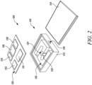
FIG. 2 shows an exploded view of a measuring system ofFIG. 1 , in accordance with an aspect of the present disclosure; -
FIG. 3 shows a flow diagram demonstrating a flow of information through some of the hardware components shown inFIG. 2 , in accordance with an aspect of the present disclosure; and -
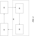
FIG. 4 shows a flow diagram of a measuring system for an electronic pressure pump, in accordance with an aspect of the present disclosure. - The present invention will be described more fully hereinafter with reference to the accompanying drawings, in which example embodiments of the invention incorporating one or more aspects of the present invention are shown. This invention may, however, be embodied in many different forms and should not be construed as limited to the embodiments set forth herein; rather, these embodiments are provided so that this disclosure will be thorough and complete, and will fully convey the scope of the invention to those skilled in the art. For example, one or more aspects of the present invention may be utilized in other embodiments and even other types of structures and/or methods. In the drawings, like numbers refer to like elements.
- Certain terminology is used herein for convenience only and is not to be taken as a limitation on the invention. For example, "upper", "lower", "front", "rear", "side", "longitudinal", "lateral", "transverse", "upwards", "downwards", "forward", "backward", "sideward", "left," "right," "horizontal," "vertical," "upward", "inner", "outer", "inward", "outward", "top", "bottom", "higher", "above", "below", "central", "middle", "intermediate", "between", "end", "adjacent", "proximate", "near", "distal", "remote", "radial", "circumferential", or the like, merely describe the configuration shown in the Figures. Indeed, the components may be oriented in any direction and the terminology, therefore, should be understood as encompassing such variations unless specified otherwise.
-
FIG. 1 shows a flow diagram for ameasuring system 100 for afluid chamber 200 containing a fluid (not shown). In some embodiments, thefluid chamber 200 may be a fluid reservoir such as a storage tank for storing the fluid. However, thefluid chamber 200 of the present disclosure may be a pump and an associated piping system that may allow the transportation or passage of the fluid. Further, the fluid may be a liquid or a gas that may be stored or transported as per the application requirements. - As illustrated in
FIGS. 2 and3 , themeasuring system 100 includes ameasuring device 120. Themeasuring device 120 is aload cell 120. Theload cell 120 is advantageously quick and precise. Further, theload cell 120 is affordable and has a longer life span. The measuringsystem 100 further includes acontroller 136 which is configured to receive a signal "S" (in the form of an output voltage "V2" or an amplified output voltage "V2'") from theload cell 120. Thecontroller 136 may be amicroprocessor 136 or a microcontroller. Thecontroller 136 based on the received signal "S" from theload cell 120 determines a fluid parameter. The fluid parameter in the present disclosure is a fluid pressure. - The fluid pressure may be a considerably important factor for evaluating a fluid flow. The rate at which the fluid flows from the piping system, or any other hydraulic or pneumatic channel depends on the pressure the fluid is under. The optimum fluid pressure may vary depending upon the application for which the fluid may be intended, and too high or too low fluid pressure may have certain disadvantages. For example, high fluid pressure may lead to leaks, damage to the pipes, and the like. Likewise, low fluid pressure may lead to an inefficient operation of the applications such as, but not limited to, spraying, showering, pumping and the like. Thus, there may be a requirement to constantly check and regulate the pressure of the flowing fluid for efficient execution of the applications for which the fluid flow may be intended.
- The
load cell 120 may be selected from one or more of a pneumatic load cell, a hydraulic load cell, a strain gauge and a capacitance load cell. The type of theload cell 120 may be selected based on the advantages, disadvantages, and suitability of the different types of theload cells 120 in different working environments. However, as illustrated inFIG. 2 , theload cell 120 of the present disclosure is a straingauge load cell 120, which will be alternatively referred to as theload cell 120 in the present disclosure. Further, theload cell 120 is an S-shaped block that may be used to measure either a compression or a tension. However, theload cell 120 with any other shape known in the art may be used without limiting the scope of the present disclosure in any manner. - A
strain gauge 122 is shown and illustrated inFIG. 2 near a center,hollow portion 124 of theload cell 120. The center of theload cell 120 is hollow to ensure that a linear output voltage "V2" from theload cell 120 is produced as a function of the strain. Further, thestrain gauge 122 may be of the type commonly known in the art that may be used to measure a strain on an object (in this case the load cell 120). Thestrain gauge 122 may preferably include an insulating flexible backing which may support a metallic deformable foil pattern. Thestrain gauge 122 may be attached to theload cell 120 by a suitable adhesive, such as a cyanoacrylate. However, thestrain gauge 122 may be attached to theload cell 120 by any other means known in the art without limiting the scope of the present disclosure. - When the foil of the
load cell 120 is deformed, the electric resistance of thestrain gauge 122 changes. Theload cell 120 may include up to fourstrain gauges 122. Preferably, the strain gauges 122 may be arranged as a Wheatstone bridge, which is a commonly known electric circuit configuration for measurement of an electrical resistance. The strain may be applied to theload cell 120 by virtue of the fluid flowing in thefluid chamber 200. Theload cell 120 is integrated with thefluid chamber 200 to provide accurate measurements. However, theload cell 120 of the present disclosure may preferably not be in direct contact with the flowing fluid. Further, the strain, due to the force of the flowing fluid, may be applied to theload cell 120 by any means known in the art without limiting the scope of the disclosure in any manner. When this strain occurs, the strain gauge 122 (and anyadditional strain gauges 122 present on the load cell 120) may detect a change in the electrical resistance. - The strain gauge or
strain gauges 122 may preferably be in electronic communication with various components of anelectronic board 130, which may be embodied as a printed circuit board, or "PCB". Various commonly known and understood electronic components are preferably mounted on thePCB 130. In a preferred embodiment, thePCB 130 includes each of anamplifier 132, an analog todigital converter 134, a microprocessor 136 (alternatively referred to as thecontroller 136 in the preferred embodiment), atransmission unit 138, and apower source 131. Thepower source 131 may be a battery. - In the preferred embodiment, as shown in
FIG. 2 , theload cell 120 and thePCB 130 are preferably contained within ahousing 140. Thehousing 140 includes abase member 142 and alid member 144. Thelid member 144 may preferably be releasably attachable to thebase member 142 in any manner known in the art, such as a friction fit, a snap fit or the like. Thehousing 140 further includes a port, or anaperture 146, located in thebase member 142. Theport 146 may be useful in some embodiments where theload cell 120 and strain gauge orstrain gauges 122 are housed separately from thePCB 130 and where wires may be required to connect theload cell 120 and thestrain gauge 122 orstrain gauges 122 to thePCB 130. - Further,
FIG. 3 shows a flow diagram that models the flow of information that preferably occurs for some of the hardware components of themeasuring system 100. As shown inFIG. 3 , thepower source 131 is responsible for providing an input voltage "V1" to the load cell 120 (though via other various electronic communications known in the art, other electronic components within the measuringsystem 100 may also be powered by the power source 131). Theload cell 120, upon detecting a change in the strain of theload cell 120 due to the fluid flowing in thefluid chamber 200, preferably causes a resistance change in the strain gauge orstrain gauges 122 of theload cell 120. Theload cell 120 then preferably outputs the signal "S" or the output voltage "V2" (associated with the change in resistance in the strain gauge or strain gauges 122) to theamplifier 132. An amplified output voltage "V2"', which is output in an analog form, is then received by the analog todigital converter 134. The analog todigital converter 134 preferably outputs a digitized output voltage "V3". - Further, a
calibration module 135 applies a calibration factor to the digitized output voltage "V3". The calibration factor is used to convert the change in voltage "V3" to a change in force "F" within theliquid chamber 200. The calculated force "F" is then subjected to asoftware module 137. Thesoftware module 137 includes a software algorithm that converts the calculated force "F" to a fluid pressure. The application of the calibration factor and the software algorithms may be carried out by themicroprocessor 136 in a manner known in the art, substantially similar to other microprocessors. - The fluid pressure of the fluid flowing in the
fluid chamber 200 is then sent via thetransmission unit 138 to a display system, remote server, or asmartphone 300. Thetransmission unit 138 may preferably be awireless transmission unit 138. Thetransmission unit 138 may communicate the fluid pressure to the display system, remote server, or thesmartphone 300 via a Bluetooth, Wi-Fi or any other known wireless transmission means. This way, a user carrying out the application employing the flowing fluid may be able to retrieve data regarding the fluid pressure in thefluid chamber 200 in real time. - In some embodiments, the fluid pressure in real time may be compared with a fluid pressure database stored in the remote server or the
smartphone 300. The fluid pressure database may include fluid pressure values or a range of fluid pressure values required for the proper execution of different types of industrial and domestic applications. In case of discrepancy between the real time fluid pressure value and the stored fluid pressure value, a wireless signal may be sent by the remote server or thesmartphone 300 so that necessary actions may be taken for the smooth execution of the application for which the fluid flow may be intended. - In some embodiments, the
fluid chamber 200 is selected from one or more of anelectronic pressure pump 202 and a pressure tank (not shown) with their associated piping system (not shown). Theelectronic pressure pump 202 and the pressure tank may generally require continuous measurement of the fluid pressure to execute any known industrial or domestic application. Hence, during the application with the one or more of the electronic pressure pumps 202 (as shown inFIG. 4 ) and the pressure tank, the measuringsystem 100 of the present disclosure is employed. The real time measured pressure is wirelessly communicated with the remote server or thesmartphone 300 and may be compared with the fluid pressure database stored in the remote server or thesmartphone 300. If the measured fluid pressure is less than the fluid pressure which may be desired for proper execution of the application, a signal is sent by the remote server or thesmartphone 300 to a controller 204 (as shown inFIG. 4 ) integrated with apump motor 206. Thecontroller 204 may then automatically turn ON thepump motor 206 to increase the fluid pressure to the desired levels. Similarly, when the measured fluid pressure reaches to the desired value, then thepump motor 206 may be turned OFF. - In some embodiments, the wireless transmission between the
transmission unit 138 and the remote server or thesmartphone 300 and further between the remote server or thesmartphone 300 and thecontroller 204 integrated with thepump motor 206 may all be carried out automatically by any means known in the art. - Thus, the present disclosure provides a cost-effective solution for the measurement of the fluid pressure in the
fluid chamber 200. The present disclosure provides a novel usage of an already known and widely usedload cell 120. - In the drawings and specification, there have been disclosed preferred embodiments and examples of the invention and, although specific terms are employed, they are used in a generic and descriptive sense only and not for the purpose of limitation of the scope of the invention being set forth in the following claims.
-
- 100
- Measuring System
- 120
- Load Cell
- 122
- Strain Gauge
- 124
- Hollow Portion
- 130
- PCB
- 131
- Power Source
- 132
- Amplifier
- 134
- Analog to digital converter
- 135
- Calibration Module
- 136
- Controller/ Microprocessor
- 137
- Software module
- 138
- Transmission Unit
- 140
- Housing
- 142
- Base Member
- 144
- Lid Member
- 146
- Port/ Aperture
- 200
- Fluid Chamber
- 202
- Electronic Pressure Pump
- 204
- Controller
- 206
- Motor
- 300
- Display System/ Remote Server/Smartphone
- V1
- Input Voltage
- V2
- Output Voltage
- V2'
- Amplified Output Voltage
- V3
- Digitized Output Voltage
- S
- Signal
- X
- Calibration Factor
- D
- Software Algorithm
- F
- Calculated force
Claims (5)
- A measuring system (100) for a fluid chamber (200) containing a fluid, comprising:a measuring device (120), wherein the measuring device (120) is a load cell (120); anda controller (136) configured to receive a signal (S, V2, V2') from the load cell (120) and determine a fluid parameter based on the received signal (S, V2, V2');characterized in that:
the fluid parameter is a fluid pressure. - The measuring system (100) of claim 1, wherein the fluid chamber (200) is selected from one or more of an electronic pressure pump (202) and a pressure tank with an associated piping system.
- The measuring system (100) of claim 2, wherein a pump motor (206) turns ON/OFF based on the fluid pressure in the one or more of the electronic pressure pumps (202) and the pressure tank and the associated piping system.
- The measuring system (100) of any of the preceding claims, wherein the load cell (120) is selected from one or more of a pneumatic load cell, a hydraulic load cell, a strain gauge, and a capacitance load cell (120).
- The measuring system (100) of any of the preceding claims, wherein the load cell (120) is integrated with the fluid chamber (200).
Priority Applications (1)
| Application Number | Priority Date | Filing Date | Title |
|---|---|---|---|
| EP22159887.3A EP4239303A1 (en) | 2022-03-03 | 2022-03-03 | Measurement of a fluid parameter |
Applications Claiming Priority (1)
| Application Number | Priority Date | Filing Date | Title |
|---|---|---|---|
| EP22159887.3A EP4239303A1 (en) | 2022-03-03 | 2022-03-03 | Measurement of a fluid parameter |
Publications (1)
| Publication Number | Publication Date |
|---|---|
| EP4239303A1 true EP4239303A1 (en) | 2023-09-06 |
Family
ID=80624966
Family Applications (1)
| Application Number | Title | Priority Date | Filing Date |
|---|---|---|---|
| EP22159887.3A Withdrawn EP4239303A1 (en) | 2022-03-03 | 2022-03-03 | Measurement of a fluid parameter |
Country Status (1)
| Country | Link |
|---|---|
| EP (1) | EP4239303A1 (en) |
Citations (3)
| Publication number | Priority date | Publication date | Assignee | Title |
|---|---|---|---|---|
| US4092856A (en) * | 1977-05-13 | 1978-06-06 | The United States Of America As Represented By The Secretary Of The Army | Kilobar range stress gauge |
| DE69314358T2 (en) * | 1993-05-19 | 1998-04-02 | Johnston Thomas H | LOAD SOCKET |
| US20170307423A1 (en) * | 2016-04-22 | 2017-10-26 | UroStat LLC | System for automated measurement of fluid output |
-
2022
- 2022-03-03 EP EP22159887.3A patent/EP4239303A1/en not_active Withdrawn
Patent Citations (3)
| Publication number | Priority date | Publication date | Assignee | Title |
|---|---|---|---|---|
| US4092856A (en) * | 1977-05-13 | 1978-06-06 | The United States Of America As Represented By The Secretary Of The Army | Kilobar range stress gauge |
| DE69314358T2 (en) * | 1993-05-19 | 1998-04-02 | Johnston Thomas H | LOAD SOCKET |
| US20170307423A1 (en) * | 2016-04-22 | 2017-10-26 | UroStat LLC | System for automated measurement of fluid output |
Similar Documents
| Publication | Publication Date | Title |
|---|---|---|
| US9140613B2 (en) | Superheat sensor | |
| US8479582B2 (en) | Pressure transmitter | |
| US8141421B2 (en) | Tank measurement system using multiple sensor elements | |
| US6452493B1 (en) | Process control instrument with multiple functions | |
| EP1241453A3 (en) | Liquid-level gauge | |
| EP3126804A1 (en) | A pressure sensor and a blower using the same | |
| US20060052968A1 (en) | Pressure and temperature compensation algorithm for use with a piezo-resistive strain gauge type pressure sensor | |
| US20120197554A1 (en) | Self-heated mems based capacitance diaphragm gauge | |
| CN115461601B (en) | Connecting sleeves for pipeline systems used to guide fluids | |
| WO2018214230A1 (en) | Single-hole cantilever beam strain gauge dynamic electronic small unmanned vehicle scale | |
| KR101059939B1 (en) | Load Cell for Displacement Water Level Transmitter | |
| US20070295095A1 (en) | Apparatus for providing an output proportional to pressure divided by temperature (P/T) | |
| US7104139B2 (en) | System and method for load sensing using piezoelectric effect | |
| CN107356363A (en) | Fluid pressure measuring device and pump equipped with such measuring device | |
| CN100374824C (en) | Temperature-pressure sensor | |
| JP2011508886A (en) | Measure and read parameters of remotely located devices | |
| US20060162419A1 (en) | Measuring device with plausibility check | |
| US20150300864A1 (en) | Liquid level sensor system | |
| EP3845102A1 (en) | Kitchen appliance with weighing apparatus | |
| CN2404102Y (en) | Internal digital display target type flowmeter | |
| EP4431896A1 (en) | Device for measuring a pressure in an interior chamber of a pressure vessel and pressure vessel equipped with such a device | |
| JPH0216417A (en) | Liquid amount measuring instrument | |
| RU2181191C1 (en) | Liquid level meter | |
| RU1768990C (en) | Weighing level gauge for liquids | |
| RU30000U1 (en) | Liquid and gas flow meter |
Legal Events
| Date | Code | Title | Description |
|---|---|---|---|
| PUAI | Public reference made under article 153(3) epc to a published international application that has entered the european phase |
Free format text: ORIGINAL CODE: 0009012 |
|
| STAA | Information on the status of an ep patent application or granted ep patent |
Free format text: STATUS: THE APPLICATION HAS BEEN PUBLISHED |
|
| AK | Designated contracting states |
Kind code of ref document: A1 Designated state(s): AL AT BE BG CH CY CZ DE DK EE ES FI FR GB GR HR HU IE IS IT LI LT LU LV MC MK MT NL NO PL PT RO RS SE SI SK SM TR |
|
| STAA | Information on the status of an ep patent application or granted ep patent |
Free format text: STATUS: THE APPLICATION IS DEEMED TO BE WITHDRAWN |
|
| 18D | Application deemed to be withdrawn |
Effective date: 20240307 |