EP4239275B1 - Materials for use in archery equipment - Google Patents
Materials for use in archery equipment Download PDFInfo
- Publication number
- EP4239275B1 EP4239275B1 EP22215603.6A EP22215603A EP4239275B1 EP 4239275 B1 EP4239275 B1 EP 4239275B1 EP 22215603 A EP22215603 A EP 22215603A EP 4239275 B1 EP4239275 B1 EP 4239275B1
- Authority
- EP
- European Patent Office
- Prior art keywords
- limb
- archery bow
- cam
- bow
- bowstring
- Prior art date
- Legal status (The legal status is an assumption and is not a legal conclusion. Google has not performed a legal analysis and makes no representation as to the accuracy of the status listed.)
- Active
Links
Images





Classifications
-
- F—MECHANICAL ENGINEERING; LIGHTING; HEATING; WEAPONS; BLASTING
- F41—WEAPONS
- F41B—WEAPONS FOR PROJECTING MISSILES WITHOUT USE OF EXPLOSIVE OR COMBUSTIBLE PROPELLANT CHARGE; WEAPONS NOT OTHERWISE PROVIDED FOR
- F41B5/00—Bows; Crossbows
- F41B5/10—Compound bows
- F41B5/105—Cams or pulleys for compound bows
-
- F—MECHANICAL ENGINEERING; LIGHTING; HEATING; WEAPONS; BLASTING
- F41—WEAPONS
- F41B—WEAPONS FOR PROJECTING MISSILES WITHOUT USE OF EXPLOSIVE OR COMBUSTIBLE PROPELLANT CHARGE; WEAPONS NOT OTHERWISE PROVIDED FOR
- F41B5/00—Bows; Crossbows
- F41B5/0005—Single stave recurve bows
- F41B5/001—Single stave recurve bows characterised by the material
-
- F—MECHANICAL ENGINEERING; LIGHTING; HEATING; WEAPONS; BLASTING
- F41—WEAPONS
- F41B—WEAPONS FOR PROJECTING MISSILES WITHOUT USE OF EXPLOSIVE OR COMBUSTIBLE PROPELLANT CHARGE; WEAPONS NOT OTHERWISE PROVIDED FOR
- F41B5/00—Bows; Crossbows
- F41B5/14—Details of bows; Accessories for arc shooting
- F41B5/1403—Details of bows
-
- F—MECHANICAL ENGINEERING; LIGHTING; HEATING; WEAPONS; BLASTING
- F41—WEAPONS
- F41B—WEAPONS FOR PROJECTING MISSILES WITHOUT USE OF EXPLOSIVE OR COMBUSTIBLE PROPELLANT CHARGE; WEAPONS NOT OTHERWISE PROVIDED FOR
- F41B5/00—Bows; Crossbows
- F41B5/14—Details of bows; Accessories for arc shooting
- F41B5/1403—Details of bows
- F41B5/1411—Bow-strings
-
- F—MECHANICAL ENGINEERING; LIGHTING; HEATING; WEAPONS; BLASTING
- F41—WEAPONS
- F41B—WEAPONS FOR PROJECTING MISSILES WITHOUT USE OF EXPLOSIVE OR COMBUSTIBLE PROPELLANT CHARGE; WEAPONS NOT OTHERWISE PROVIDED FOR
- F41B5/00—Bows; Crossbows
- F41B5/14—Details of bows; Accessories for arc shooting
- F41B5/1403—Details of bows
- F41B5/1426—Bow stabilisers or vibration dampers
-
- F—MECHANICAL ENGINEERING; LIGHTING; HEATING; WEAPONS; BLASTING
- F41—WEAPONS
- F41J—TARGETS; TARGET RANGES; BULLET CATCHERS
- F41J3/00—Targets for arrows or darts, e.g. for sporting or amusement purposes
- F41J3/0004—Archery targets
Definitions
- the present disclosure generally relates to archery equipment and specifically relates to an archery bow incorporating Non-Newtonian materials.
- Bowhunters and other archers use finely tuned archery equipment to improve performance.
- Various modifications and accessories to their equipment can improve the accuracy, efficiency, convenience, safety, and, in some cases, sound of their archery bows.
- Reduction of vibrations is one modification of frequent interest.
- a projectile such as an arrow
- the limbs, bowstring, and other connected elements of the bow will vibrate as the energy stored in the limbs and is transferred to the projectile.
- the vibrations can cause archer fatigue, can induce errant movements of the bow or projectile, can reduce the life of the equipment, and can cause unwanted noise, among other things. Accordingly, there is a constant need for improvements to various types of archery equipment that reduce or dampen vibrations.
- US 2014/0041645 relates to an archery bow limb dampening system, and discloses an archery bow according to the pre-amble of the appended independent claims.
- US10345072 relates to a flexible string damper.
- EP3736522 relates to an archery bow limb adjustment system.
- US 2017/0030674 relates to an archery bow limb support apparatus and method.
- an archery bow as defined in either independent claim 1 or independent claim 12.
- Embodiments of the present invention are defined in appended claims dependent on either independent claim 1 or independent claim 12.
- One aspect of the present invention relates to an archery bow including a riser, a first limb, a second limb, and a bowstring.
- the first and second limbs are coupled to the riser.
- the bowstring extends between the first and second limbs.
- At least one of the riser, the first limb, the second limb, or the bowstring include a Non-Newtonian Material (NN material).
- N material Non-Newtonian Material
- a viscosity of the NN material can be configured to temporarily increase when a projectile is launched from the archery bow.
- the viscosity of the NN material can be configured to temporarily decrease when a projectile is launched from the archery bow.
- the NN material can be coupled to the riser in some embodiments.
- the first limb can include a first portion of the NN material and the second limb can include a second portion of the NN material.
- the first limb can define a length and a portion of NN material can extend along a majority of the length.
- the NN material can be coupled to a portion of the bowstring extending between the first limb and the second limb.
- the NN material can include a polymer.
- the archery bow can be a compound bow, a recurve bow, or a crossbow.
- an archery bow which includes a riser, a first limb, a second limb, a string, and an accessory component.
- the first limb is coupled to a first end of the riser.
- the second limb is coupled to a second end of the riser.
- the string extends between the first limb and the second limb.
- the accessory component is coupled to at least one of the riser, the first limb, the second limb, or the string.
- the accessory component includes a NN material.
- the NN material can have a viscosity configured to temporarily increase when the projectile is launched from the archery bow.
- the NN material can be disposed within a cavity formed by the shaft.
- the NN material can be a first portion of NN material and the projectile can further include a second portion of NN material disposed within the cavity.
- the first portion of NN material can be displaced from the second portion of NN material by a distance.
- the NN material can be disposed within the cavity at a distance from the proximal end of the shaft.
- the NN material can be disposed within the cavity at a distance from a distal end of the shaft.
- the shaft can include at least one of carbon fiber or aluminum alloy.
- a Non-Newtonian Material can be affixed, molded, adhered, or otherwise incorporated into one or more components of an archery bow, an archery accessory, or a combination thereof. Incorporation of a NN material can reduce or eliminate vibration and/or sound resultant from launching a projectile (e.g., a bolt, an arrow, etc.) or provide other benefits, such as, increased durability.
- a Non-Newtonian (NN) material is a material that exhibits rate-sensitive characteristics relative to stress vs. strain properties depending on the rate of loading. Newtonian material exhibit characteristics with stress vs.
- Non-Newtonian (NN) materials have traditionally been fluids.
- a Non-Newtonian fluid the relation between shear stress and the shear rate is non-linear and dependent on the rate of loading while a Newtonian fluid has a constant relation between the shear stress and shear rate, defined as the viscosity.
- N Non-Newtonian
- the term viscosity is used to identify the material property which expresses the magnitude of internal friction and resistance to change in shape or movement (deformation) of the material.
- the NN material can have material attributes, such as viscosity, which vary based on a quantity of rate of stress (e.g., shear force) applied to the NN material.
- NN materials can have a viscosity that is not independent of the rate of stress applied to the material.
- the resistance to deformation of an NN material can increase or decrease an amount that correlates with a rate of force (shear, tensile, etc.) applied (loading rate) to the NN material.
- the attribute, such as the viscosity of the NN material can have a nonlinear correlation with a rate of shear stress or rate of force applied to the NN material.
- Examples of NN materials can include any material currently available or otherwise produced having a viscosity that is dependent upon a rate of stress or load applied to the material.
- a static state is the slow rate of application of force to a material and can be used to describe loading rates similar to the action of an archer drawing a bow.
- a dynamic state is the fast rate of application of force to an object and can be used to describe loading rates similar to the action of firing a bow
- NN fluids are cornstarch suspended in water (e.g., oobleck), wall paint, toothpaste, ketchup, and blood.
- non-fluid NN materials can include Poron ® 4701-30 Polyurethane and D30 ® polymer. While only a limited number of specific examples of NN materials are expressly referenced, any NN materials which are currently existing or subsequently developed can be used to realize the aspects of this disclosure.
- Some NN materials can be shear thickening wherein the viscosity increases as the rate of force (e.g., shear, tensile, etc .) is increased.
- the viscosity of a shear thickening NN material can increase when the NN material undergoes a dynamic event (e.g., a projectile is launched from the archery bow).
- some NN materials are shear thinning wherein the viscosity decreases as the rate of force (e.g., shear, tensile, etc .) is increased.
- the viscosity of a shear thinning NN material can decrease when the NN material undergoes a dynamic event (e.g., a projectile is launched from the archery bow).
- NN materials can be incorporated into the archery bow to alter the vibrational characteristics of the archery bow during and after a shot event ( i . e ., when a projectile is launched from the archery bow) relative to the state ( e.g., dynamic and/or static) of the archery bow.
- the NN material can reduce or eliminate at least one of high-frequency vibrations and low-frequency vibrations to improve the performance of the archery bow and shooting experience for the archer.
- a shear thickening material will resist deformation in a dynamic state.
- Shear thickening materials can be effective as an outer layer to protect against impact as the material will resist a localized high rate of deformation and spread it across a larger non-localized area. Shear thickening materials can also be effective at increasing the dynamic stiffness of a structure and altering the structure's natural frequency of response during a dynamic event.
- the NN material can act as a material which has a dynamic natural response frequency which is significantly different than the material's static natural response frequency. The difference in static and dynamic natural frequencies of the same object promotes an effective damping behavior which prevents the occurrence of resonance.
- a shear thinning NN material, a shear thickening NN material, or a combination thereof can be incorporated into one or more components of an archery bow to provide variable dampening which correlates to loads exerted on the one or more components.
- the limbs, string, riser, another component of the archery bow, or a combination thereof can include NN material to reduce or eliminate vibration and/or sound resultant from launching a projectile.
- the limbs, string, riser, another component of the archery bow, or a combination thereof can include NN material to reduce or eliminate damage resultant from an object contacting the archery bow.
- a shear thickening NN material can be incorporated into the limbs of the archery bow to reduce or prevent limb splinters when the archery bow is dropped onto a hard surface or object (e.g., dropped from a tree stand onto a rock or log).
- a shear thickening NN material can be incorporated onto a string groove of a recurve limb to mitigate damage to the limb caused by the bowstring repeatedly impacting the string groove when a projectile is launched from the recurve bow.
- FIG. 1 shows an archery bow 100 according to an embodiment of the present disclosure.
- the bow 100 is at a rest position (e.g., a brace position).
- the bow 100 can comprise a riser 102 from which one or more upper limbs 104 and one or more lower limbs 106 extend.
- the riser 102 can comprise a handle portion 107 (i.e., a grip), a sight window portion 108, a roller guard or cable guard 110, a string-stop damper 112, and other parts and accessories commonly known in the art.
- the upper limbs 104 can be connected to an upper cam 114, and the lower limbs 106 can be connected to a lower cam 116.
- a bowstring 118 (i.e., draw string) can extend across the length of the bow 100 between the upper cam 114 and the lower cam 116 when the bow 100 is positioned vertically upright in a normal shooting orientation.
- the terminal ends of the bowstring 118 can be attached to and held wrapped against the cams 114, 116, at least in the brace position, and the limbs 104, 106 can be flexed to store energy and retain tension in the bowstring 118.
- a first cable 120 and a second cable 122 can also be attached to and extend between the upper cam 114 and the lower cam 116.
- first cable 120 and the second cable 122 can be referred to herein as the cables of the bow 100.
- the first and second cables 120, 122 can retain tension in the limbs 104, 106 and cams 114, 116 and can be controlled to adjust tension in the bowstring 118, draw length of the bowstring 118, and other tuning features of the bow 100.
- the bow 100 is a compound bow
- the components of the archery bow, accessories, and related methods and apparatuses included in embodiments of the present disclosure can be applied to components and apparatuses in traditional bows, compound bows, recurve bows, crossbows, their accessories, and other related archery equipment.
- archery equipment applying the teachings of the present disclosure does not need to implement all of the features of the present disclosure.
- the bow may not comprise a cable guard 110 or a string-stop damper 112, so features associated with those accessories can be omitted from the bow.
- the tail end of the arrow can be nocked with the bowstring 118 at a nocking point while the bow 100 is in the rest position shown in FIG. 1 .
- the bowstring 118 can be drawn rearward to a full draw position, thereby partially unraveling the bowstring 118 from the outer grooves of the cams 114, 116.
- the archer can grip the handle portion 107 of the riser 102 and draw back the bowstring 118 ( e.g., by using a well-known D-loop).
- the cables 120, 122 can slide along or can be in rolling contact with portions of the cable guard 110, which can comprise at least one roller or other smooth support in contact with the cables 120, 122 where they contact the cable guard 110.
- the bowstring 118 When the bowstring 118 is released, the potential/stored energy in the limbs 104, 106 is released, and the bowstring 118 quickly accelerates back toward the rest position (shown in FIG. 1 ) as it applies a shooting force to an end of the projectile (e.g., an arrow). As the limbs 104, 106 release their energy, they spread apart, and the terminal ends of the bowstring 118 wrap around the cams 114, 116, and the cables 120, 122 unwind from the cams 114, 116.
- an end of the projectile e.g., an arrow
- a portion of the bowstring 118 can come into contact with the string-stop damper 112, which can help dampen vibrations in the bowstring 118, and the cables 120, 122 can roll or slide against the cable guard 110 as the cams 114, 116 move. Vibrations and reverberations in the bow 100 can dampen out, at least partially due to dampening provided by an NN material incorporated into one or more components of the bow 100, and bow 100 can return to the brace position shown in FIG. 1 . In this process, the cams 114, 116 and at least one roller can rotate relative to the limbs 104, 106 or cable guard 110 of the bow 100.
- Vibration resultant from launching the projectile can negatively affect an archer's aim and accuracy, the structure and tuning of the bow, and the lifespan of the strings and other parts of the bow 100. Vibration also contributes to the loudness of noise made by the shooting the bow 100. Accordingly, among other benefits, aspects of the present disclosure relate to vibration dampening and related methods that can be used to address challenges faced by archers and archery products manufacturers.
- FIGS. 2-5B show various examples of limbs for archery bows which incorporate one or more NN materials to reduce or limit vibration of an archery bow. While these examples illustrate the one or more portions of NN material at particular positions within or on the limb(s), these examples should not be considered limiting as this disclosure anticipates NN material disposed in one or more locations anywhere on or within one or more limbs.
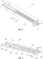
- FIG. 2 is an isometric view of a limb 200 of an archery bow, according to some embodiments.
- the limb 200 can be a singular top or singular bottom limb of an archery bow ( e.g., an archery bow with a single upper limb and a single lower limb).
- the limb 200 can be one of a pair of limbs of an archery bow, such as, the upper limbs or lower limbs of the archery bow 100 shown in FIG. 1 .
- the limb 200 can include a proximal end 202, a distal end 204, and an intermediate portion 206 disposed between the distal and the proximal ends 204, 202.
- the proximal end 202 can be fastened, affixed, or otherwise coupled to a riser ( e.g., riser 102), for example, by a limb pocket or other component fastened to the riser.
- the distal end 204 can include a through-hole 208 or other feature which enable a cam (e.g., upper or lower cam 114, 116) to be rotatably coupled to the limb 200.
- the limb 200 can include one or more portions of NN material 210A, 210B disposed on or within the limb 200.
- the one or more portions of NN material 210A, 210B can be disposed between layers of other materials that form the limb 200, such as, between layers of fiberglass, carbon fiber, or another glass reinforced material.
- the one or more portions of NN material 210A, 210B can extend along the intermediate portion 206 of the limb 200.
- the one or more portions of NN material 210A, 210B can extend a majority of a length L between the proximal end 202 and the distal end 204.
- the one or more portions of NN material 210A, 210B may not extend a majority of the length L between the proximal end 202 and the distal end 204.
- the one or more portions of NN material 210A, 210B can be offset or spaced a distance D 1 from the distal end 204 of the limb 200.
- the distance D 1 can be less than about 5 millimeters, between about 5 millimeters and about 20 millimeters, between about 20 millimeters and about 50 millimeters, between about 50 millimeters and about 100 millimeters, or greater than 100 millimeters.
- the one or more portions of NN material 210A, 210B can be disposed flush with or at the distal end 204 of the limb 200.
- the one or more portions of NN material 210A, 210B can be offset or spaced a distance D 2 from the proximal end 202 of the limb 200.
- the distance D 2 can be less than about 5 millimeters, between about 5 millimeters and about 20 millimeters, between about 20 millimeters and about 50 millimeters, between about 50 millimeters and about 100 millimeters, or greater than 100 millimeters.
- the one or more portions of NN material 210A, 210B can be disposed flush with or at the proximal end 202 of the limb 200.
- the one or more portions of NN material 210A, 210B can be disposed nearer the distal end 204 of the limb 200 than the proximal end 202 of the limb 200.
- the one or more portions of NN material 210A, 210B can be disposed nearer the proximal end 202 of the limb 200 than the distal end 204 of the limb 200.
- the limb 200 can form a first surface 212 that is in tension when the limb 200 is under a load and a second surface 214 that is in compression when the limb 200 is under a load.
- One or more portions of NN material 210A, 210B can be disposed on one or more of the first and second surfaces 212, 214 ( i.e., adhered or otherwise affixed to one or both of the first and second surfaces 212, 214). Additionally, or alternatively, one or more portions of NN material 210A, 210B can be disposed between the first and second surfaces 212, 214.
- the limb 200 can be formed from distinct layers of material that are adhered or otherwise affixed to form the limb 200.
- One or more portions of the NN material can be disposed between the distinct layers of material that form the limb 200.
- the one or more portions of NN material 210A, 210B can be disposed nearer the first surface 212 of the limb 200 than the second surface 214 of the limb 200.
- the one or more portions of NN material 210A, 210B can be disposed nearer the second surface 214 of the limb 200 than the first surface 212 of the limb 200.
- the one or more portions of NN material 210A, 210B can be disposed within or on the limb 200, such that, the one or more portions of NN material 210A, 210B are symmetrical about a centerline C L extending longitudinally along the center of the limb 200.
- the centerline C L can be an axis or a plane that extends from the proximal end 202 to the distal end 204 of the limb 200.
- the centerline C L is positioned between the longitudinal sides of the limb 200.
- Longitudinal symmetry of the one or more portions of NN material 210A, 210B about the centerline C L can be beneficial to limit or prevent the limb from twisting or torqueing along the centerline C L while under load. While the one or more portions of NN material 210A, 210B are illustrated as two distinct portions extending on either side of the centerline C L in FIG. 2 , a single portion of NN material can alternatively, or additionally, be incorporated into the limb ( see FIG. 3 ). Moreover, while the one or more portions of NN material 210A, 210B are illustrated as two distinct portions extending side by side in FIG.
- two or more portions of NN material extending sequentially (one after the other) along the centerline C L can alternatively, or additionally, be incorporated into the limb.
- the one or more portions of NN material 210A, 210B can be purposefully non-symmetric with respect to the centerline CL so as to create a dynamic balancing offset of undesirable torque induced in the cam and/or limb due to shifting of tensions from cables (offset relative to a central point between the limbs) to the bowstring (centered between the limbs).
- a viscosity of the one or more portions of NN material 210A, 210B can vary, such that the NN material better absorbs vibrations resultant launching a projectile from the bow.
- the one or more portions of NN material 210A, 21 0B can have a first viscosity prior to the projectile being launched from the bow and have a second viscosity immediately after the projectile is launched from the bow.
- the variance between the first viscosity and second viscosity can be directly related to loading rates of forces or loading rates of stresses applied to the one or more portions of NN material 210A, 210B resultant from vibrations generated by launching the projectile.
- the first viscosity can be greater than the second viscosity. Alternatively, in some embodiments, the first viscosity can be less than the second viscosity. This variance in viscosity of the one or more portions of NN material 210A, 210B can better dampen vibrations to reduce or eliminate the vibration and/or sound resultant from launching a projectile from the bow.
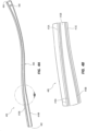
- FIG. 3 is an isometric view of a pair of limbs 300A, 300B of an archery bow, according to some embodiments.
- Each limb of the pair of limbs 300A, 300B can be similar to, and can include some or all of, the features of the limb 200.
- each limb of the pair of limbs 300A, 300B can include a proximal end 302A, 302B, a distal end 304A, 304B, and an intermediate portion 306A, 306B disposed between the distal end 302A, 302B and the proximal end 304A, 304B.
- the respective distal ends 304A, 304B can include respective through-holes 308A, 308B or other features which enable a cam (e.g., upper or lower cam 114, 116) to be rotatably coupled between the limbs 300A, 300B.
- Each of the limbs 300A, 300B can include a portion of NN material 310A, 310B.
- the respective portions of NN material 310A, 310B can be adhered, coupled, or otherwise affixed to a first surface 312A, 312B of the limb (e.g., a surface under tension while the limb is loaded).
- the respective portions of NN material 310A, 310B can be adhered, coupled, or otherwise affixed to a second surface 314A, 314B of the limb (e.g., a surface in compression while the limb is loaded).
- portion of NN material 310A is illustrated at a particular location on the intermediate portion 306A of the limb 300A with respect to the proximal and distal ends 302A, 304A
- the portion of NN material 310A can be disposed at any distance ( e.g., distances D 1 , D 2 shown in FIG. 2 ) with respect to the proximal and distal ends 302A, 304A.
- the portion of NN material 310B can be disposed at any distance ( e.g., distances D 1 , D 2 shown in FIG. 2 ) with respect to the proximal and distal ends 302B, 304B of limb 300B.
- the portions of NN material 310A, 310B can be disposed within or on the respective limbs 300A, 300B, such that, the one or more portions of NN material 310A, 310B are symmetrical about a centerline ( see centerline C L of FIG. 2 ) extending longitudinally along the center of each of the limbs 300A, 300B.
- the portion of NN material 310A can be identically shaped, sized, and positioned on limb 300A as the portion of NN material 310B disposed on limb 300B, such that, the portions of NN material 310A, 310B are symmetrical or mirrored when the limbs 300A, 300B are coupled to an archery bow.
- each of the portions of NN material 310A, 310B are shown as singular or unitary pieces of material in FIG. 3
- one or both of the portions of NN material 310A, 310B can be formed of multiple distinct pieces of NN material that are disposed on the limb 300A, 300B.
- each of the multiple distinct pieces of NN material can be layer, placed side-by-side, or a combination thereof.
- each of the multiple distinct pieces of NN material can be spaced apart from one another ( e.g., separated by a Newtonian material or an air gap).
- the NN material can provide dynamic dampening which varies relative to stresses or forces exerted on the one or more components having NN material.
- the limbs, another component of the archery bow, or a combination thereof can include NN material to reduce or eliminate vibration and/or sound resultant from launching a projectile.
- the NN material can reduce or mitigate damage resultant from an object contacting the archery bow.
- a shear thickening NN material can be incorporated into the limbs or riser of the archery bow to reduce or prevent damage from an impact (localized dynamic external force - e.g., dropping the bow, transportation hazards, etc.).
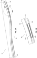
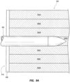
- FIGS. 4A and 4B show a side view and a detailed side view of a limb 400 of an archery bow, according to some embodiments.
- the limb 400 can be similar to, and can include some or all of, the features of the limbs 200, 300A, 300B.
- the limb 400 can include a proximal end 402 a distal end 404, and an intermediate portion 406 disposed between the distal end 402 and the proximal end 404.
- the distal end 404 can include a through-hole 408 or other feature which enables a cam (e.g., upper or lower cam 114, 116) to be rotatably coupled to the limb 400.
- a cam e.g., upper or lower cam 114, 116
- the limb 400 can include first and second portions of NN material 410A, 410B incorporated as layers within the limb 400.
- the first and second portions of NN material 410A, 410B can be adhered, coupled, or otherwise affixed between other layers of material (layers 412A, 412B, 412C) of the limb 400 ( e.g., adhered between layers of the limb 400 formed from fiberglass or another material).
- Each of the portions of NN material 410A, 410B can extend continuously between the proximal and distal ends 402, 404 of the limb 400.
- one or more of the portions of NN material 410A, 410B can extend discontinuously between the proximal and distal ends 402, 404 of the limb 400.
- the portion of NN material 410A can be formed from two or more distinct pieces of NN material that are evenly spaced between the proximal and distal ends 402, 404 of the limb 400.
- FIGS. 5A and 5B show a side view and a detailed side view of a limb 500 of an archery bow, according to some embodiments.
- the limb 500 can be similar to, and can include some or all of, the features of the limbs 200, 300A, 300B, 400.
- the limb 500 can include a proximal end 502 a distal end 504, and an intermediate portion 506 disposed between the distal end 502 and the proximal end 504.
- the distal end 504 can include a through-hole 508 or other feature which enables a cam (e.g., upper or lower cam 114, 116) to be rotatably coupled to the limb 500.
- a cam e.g., upper or lower cam 114, 116
- the limb 500 can include first and second portions of NN material 510A, 510B incorporated within the limb 500.
- the first and second portions of NN material 510A, 510B can be adhered, coupled, or otherwise affixed between other layers of material (layers 512A, 512B, 512C) of the limb 500 (e.g., adhered between layers of the limb 500 formed from fiberglass or another Newtonian material).
- Each of the portions of NN material 510A, 510B can extend only a portion of the length L extending between the proximal and distal ends 502, 504 of the limb 500.
- each of the portions of NN material 510A, 510B can extend less than half or less than a quarter of the length L extending between the proximal and distal ends 502, 504 of the limb 500.
- each of the portions of NN material 510A, 510B can extend more than half or more than three-quarters of the length L extending between the proximal and distal ends 502, 504 of the limb 500.
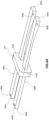
- FIG. 6A is an isometric view of a pair of limbs 600A, 600B of an archery bow, according to some embodiments.
- Each limb of the pair of limbs 600A, 600B can be similar to, and can include some or all of, the features of the limb 200, 300A, 300B, 400, 500.
- each limb of the pair of limbs 600A, 600B can include a proximal end 602A, 602B, a distal end 604A, 604B, and an intermediate portion 606A, 606A disposed between the distal end 602A, 602B and the proximal end 604A, 604B.
- the respective distal ends 604A, 604B can include respective through-holes 608A, 608B or other features which enable a cam (e.g., upper or lower cam 114, 116) to be rotatably coupled between the limbs 600A, 600B.
- a cam e.g., upper or lower cam 114, 116
- an accessory component e.g., a damping member 610 can be coupled to or otherwise contact at least one of the limbs 600A, 600B.
- the damping member 610 can contact each of the limbs 600A, 600B to dampen vibrations resultant from launching a projectile from the archery bow.
- the damping member 610 can be formed using a NN material which has a viscosity that varies relative to rates of forces or rates of stresses applied to the damping member 610.
- the damping member 610 can include first and second apertures 612A, 612B sized and shaped to enable each limb 600A, 600B to extend through the dampening member 610.
- the damping member 610 can be adhered, fastened, molded, tied, clipped, or otherwise coupled to one or both of the limbs 600A, 600B.
- the damping member 610 can act as a tether or link which stiffens when a stress or force is applied, such that, the limbs 600A, 600B are effectively or substantially interlocked and flex as a singular structure to resist torsion or twisting.
- the damping member 610 prior to launching a projectile (e.g., when the archery bow is in a static state), the damping member 610 can be relatively less rigid or less stiff, such that, each of the limbs 600A, 600B can flex and bend independently of one another.
- the damping member 610 can be held in contact with one or both of the limbs 600A, 600B by a support structure (not shown) extending from a riser ( e.g., riser 102) or a pocket coupled to the riser. While the damper member 610 is illustrated as cubic having a rectangular cross-sectional shape, the damper member 610 can form any geometric shape or non-geometric shape having any geometric or non-geometric cross-sectional shape.
- damping member 610 is illustrated as contacting particular locations on the intermediate portions 606A, 606B of the limbs 600A, 600B with respect to the proximal ends 602A, 602B and distal ends 604A, 604B, the damping member 610 can be disposed at any distance ( e.g., distances D 1 , D 2 shown in FIG. 2 ) with respect to the proximal ends 602A, 602B and distal ends 604A, 604B.
- the damping member 610 is shown as singular or unitary piece of NN material in FIG. 6A , the damping member 610 can be formed of multiple distinct pieces of NN material that are molded, adhered, fastened, or otherwise coupled together. Alternatively, or additionally, the damping member 610 can be formed from a combination of NN material and Newtonian material, such that, only a portion of the damping member 610 has a viscosity that varies relative to forces or stress applied to the damping member 610. For example, the damping member 610 can be co-molded using NN material and Newtonian material.
- FIG. 6B is an isometric view of the pair of limbs 600A, 600B including an accessory component (e.g., a damping member 614) coupled to or otherwise contacting at least one of the limbs 600A, 600B.
- the damping member 614 can contact each of the limbs 600A, 600B to dampen vibrations resultant from launching a projectile from the archery bow.
- the damping member 614 can be formed using a NN material which has a viscosity that varies relative to a rate of force or rate of stress applied to the damping member 614.
- the damping member 614 can be similar to, and can include some or all of, the features of the damping member 610.
- the damping member 614 can include first and second apertures 612A, 612B sized and shaped to enable each limb 600A, 600B to extend through the dampening member 614.
- the damping member 614 can be adhered, fastened, molded, tied, clipped, or otherwise coupled to one or both of the limbs 600A, 600B.
- the damping member 614 can act as a tether or link which stiffens when a stress or force is applied, such that, the limbs 600A, 600B are effectively or substantially interlocked and flex as a singular structure to resist torsion or twisting.
- the damping member 614 can be relatively less rigid or less stiff, such that, each of the limbs 600A, 600B can flex and bend independently of one another.
- the damping member 614 illustrated in FIG. 6B can contact non-symmetrical locations on the intermediate portions 606A, 606B of the limbs 600A, 600B with respect to the proximal ends 602A, 602B and distal ends 604A, 604B.
- the damping member 614 can contact the limb 600A at a first distance from the proximal end 602A while the damping member 614 can contact the limb 600B at a second distance from the proximal end 602B.
- the first and second distances can be different, such that, the damping member 614 affects the movement of each limb 600A, 600B differently when a projectile is launched from the archery bow.
- Contacting the limbs 600A, 600B at non-symmetrical locations can alter movement characteristics of one or both limbs 600A, 600B to increase performance of the archery bow. For example, altering the movement characteristics of one or both limbs 600A, 600B can offset undesirable torque induced in the cam and/or limb due to shifting of tensions from cables (offset relative to a central point between the limbs) to the bowstring (centered between the limbs).
- the damping member 614 is shown as singular or unitary piece of NN material in FIG. 6B , the damping member 614 can be formed of multiple distinct pieces of NN material that are molded, adhered, fastened, or otherwise coupled together. Alternatively, or additionally, the damping member 614 can be formed from a combination of NN material and Newtonian material, such that, only a portion of the damping member 614 has a viscosity that varies relative to loading rates of forces or stresses applied to the damping member 614. For example, the damping member 614 can be co-molded using NN material and Newtonian material.
- FIGS. 1-6B described various example embodiments where NN materials were incorporated into or on one or more limbs of the archery bow
- other components of the archery bow such as, the bowstring, cables, riser, sight, stabilizer, quiver, rest, or other component can additionally, or alternatively, include a NN material or an accessory component incorporating a NN material.
- one or more accessory components incorporating NN material can be adhered, fastened, clipped, crimped, molded, welded, bonded, inserted, or otherwise affixed to one or more components of the archery bow.
- one or more accessory components incorporating NN material can be fastened or otherwise coupled to an external surface of a riser.
- one or more portions of NN material can be disposed within one or more cavities formed within a riser having a hollow tubular structure, such as, a riser formed from one or more carbon fiber tubes.
- the one or more portions of NN material can mitigate or reduce vibration resultant of launching a projectile from the archery bow.
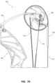
- FIG. 7A is a detail view of a portion of an archery bow 700, according to some embodiments.
- the archery bow 700 can be substantially similar to, and can include some or all of, the features of the archery bow 100.
- the archery bow 700 can include a riser 702, a limb 704, an upper cam 708, a first cable 710, a second cable 712, and a bowstring 714.
- the archery bow 700 can include one or more string dampers 716 coupled to the bowstring 714 and configured to reduce or mitigate vibration resultant from launching a projectile from the archery bow 700.
- the string damper 716 can be at least partially formed from a NN material, such that, a viscosity of the string damper 716 can vary relative to a rate of force or rate of stress applied to the string damper 716.
- the one or more string dampers 716 can be at least partially formed of a NN material, such as, a polymer or Non-Newtonian fluid (NN fluid).
- NN fluid Non-Newtonian fluid
- the string damper 716 can be formed from an outer container or vessel at least partially filled within an NN fluid and subsequently coupled or affixed to the bowstring 714.
- the NN material (e.g., a shear thickening NN fluid) incorporated into the string damper 716 can become rigid or otherwise have a relatively higher viscosity when a high rate of stress or high rate of forces are induced on the string damper 716 (e.g., when a projectile is launched from the archery bow 700) to cause the portion of the bowstring 714 adjacent the string damper 716 to resist bending and deformation.
- a shear thickening NN fluid e.g., a shear thickening NN fluid
- the NN material (e.g., a shear thinning NN fluid) incorporated into the string damper 716 can become flexible or otherwise have a relatively lower viscosity when stress or forces are induced on the string damper 716 (e.g., when a projectile is launched from the archery bow 700).
- the non-linear correlation between viscosity and stress or force of the string damper 716 can be beneficial, for example, in mitigating or reducing vibrations resultant of a projectile being launched from the archery bow 700.
- a temporarily rigid or stiff string damper 716 can cause at least a portion of the bowstring 714 to resist bending and deformation immediately after the projectile is launched from the bowstring 714.
- the string damper 716 can be disposed anywhere along the section of the bowstring 714 extending between the upper cam 708 and the lower cam (now shown). For example, as shown in FIG. 7A , the string damper 716 can be disposed on the bowstring 714 near the upper cam 708. Alternatively, or additionally, the string damper 716 can be disposed on the bowstring 714 near a lower cam (not shown) of the archery bow 700.
- the string damper 716 can form any geometric or non-geometric shape. In some embodiments, the string damper 716 can extend parallel to the bowstring 714, as shown in FIG. 7A . In other embodiments, the string damper 716 can extend perpendicular to the bowstring 714.
- the string damper 716 is shown as singular or unitary piece of NN material in FIG. 7A , the string damper 716 can be formed of multiple distinct pieces of NN material that are molded, adhered, fastened, or otherwise coupled together. Alternatively, or additionally, the string damper 716 can be formed from a combination of NN material and Newtonian material, such that, only a portion of the string damper 716 has a viscosity that varies relative to rate of forces or rate of stress applied to the string damper 716. For example, the string damper 716 can be co-molded using a combination of an NN material and a Newtonian material.
- the string damper 716 can be crimped around the bowstring 714 to couple the string damper 716 to the bowstring 714.
- the string damper 716 can include one or more apertures which enable the bowstring 714 to extend through the string damper 716 to couple the string damper 716 to the bowstring 714.
- the string damper 716 can be adhered, fastened, molded, tied, clipped, or otherwise coupled to the bowstring 714. While the string damper 716 is shown in FIG. 7A as being coupled to the bowstring 714, one or more string dampeners incorporating NN material can additionally, or alternatively, be affixed to the first cable 710 and/or the second cable 712.
- NN materials can be additionally, or alternatively, incorporated into one or more of the cams (e.g., upper cam 114 and lower cam 116 shown in FIG. 1 ).
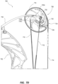
- the upper cam 708 can include a string track 718 extending around a periphery of the upper cam 708.
- the string track 718 can define a depth which partially receives the bowstring 714.
- the string track 718 can have a diameter that sufficiently catches and retains the bowstring 714 to prevent the bowstring 714 from derailing or unintentionally exiting the string track 718.
- the string track 718 can be at least partially supported by one or more spokes or structural members 720A, 720B, 720C of the upper cam 708.
- the one or more structural members 720A-720C can define apertures or through-holes within the upper cam 708, such that, the one or more structural members 720A-720C generally extend radially between an axis of rotation 722 of the upper cam 708 and the string track 718. While the structural members 720A-720C are depicted as a spoke system, the structural members 720A-720C can be formed as any other support structure, for example, a hexagonal support structure or other support structure.
- the one or more structural members 720A-720C can prevent the upper cam 708 from bending or breaking from significant loading induced on the upper cam 708 when an arrow is launched from the archery bow. For example, when the bowstring is released and the archery bow transitions from a fully drawn state to a brace state ( i.e., the state shown in FIG. 1 ), the upper cam 708 is abruptly prevented from continued rotation by the cables 710, 712 and the bowstring 714. This abrupt stop can induce vibrations and other forces into the archery bow which can cause archer fatigue, can induce errant movements of the bow or projectile, can reduce the life of the archery bow, and can generate unwanted noise.
- one or more of the structural members 720A-720C can be entirely or partially formed from an NN material.
- One or more structural members 720A-720C formed from one or more types of NN material can reduce or eliminate at least one of high-frequency vibrations and low-frequency vibrations to increase the longevity of the archery bow, improve the performance of the archery bow, and improve the shooting experience for the archer.
- one or more structural members 720A-720C can be formed from a shear thickening NN material which has a stiffness that correlates to a change in the rate of forces applied to the upper cam 708.
- FIG. 7C is a detail view of a portion of an archery bow 700 including a NN material incorporated as a damper 724 into the upper cam 708.
- the damper 724 can be sized and shaped to fit within a recess or aperture formed within the upper cam 708.
- a portion of the damper 724 can be disposed within the string track 718 and contact the bowstring 714.
- the damper 724 can be disposed within a recess or through-hole that is in fluid communication with the string track 718, such that, a portion of the damper 724 extends from the recess or through-hole into the string track 718.
- damper 724 is depicted as being disposed at or near a rear-ward lobe 726 of the upper cam 708, one or more dampers 724 can be disposed anywhere on the upper cam 708 in other embodiments.
- one or more dampers 724 can be disposed within a recess or through-hole formed by any other element of the upper cam 708 ( e.g., the string track 718, the one or more structural members 720A-720C, apertures 728A-728C, slots 730A, 730B, a combination thereof, etc . ).
- the damper 724 can be adhered, fastened, tied, molded, or otherwise coupled to an element of the upper cam 708, such as, the one or more support members 720A-720C.
- FIG. 7D is a detail view of a portion of an archery bow 700 including a NN material 732 incorporated as the lobe 726 of the upper cam 708.
- the NN material 732 can be adhered, fastened, welded, molded, or otherwise coupled to the upper cam 708. While the NN material 732 is shown in a particular positon on the upper cam 708 and having a particular shape in FIG. 7D , the NN material 732 can be disposed anywhere on the upper cam 708 and define any shape. Moreover, all of the principles discussed herein are equally applicable to a lower cam ( e.g., lower cam 116 shown in FIG. 1 ).
- the NN material 732 can form or define a portion of the string track 718, such that, a section of the bowstring 714 comes into contact with the NN material 732 when a projectile is launched from the archery bow.
- a section 734 of the bowstring 714 can slap or impact the NN material 732 when the archery bow reaches a brace condition ( see FIG. 1 ) and the projectile is launched from the bowstring 714.
- This slap or impact can exert a significant and near-instantaneous force on the NN material 732 to cause the NN material 732 to rapidly increase in stiffness or rigidity to better absorb the impact and reduce or prevent damage caused by the impact.
- the NN material 732 can have a resistance to deformation that increase at a rate that correlates with a rate of force generated by the impact of the section 734 of the bowstring 714 upon the NN material 732. Even if a relatively rigid Newtonian material were substituted for the NN material 732, the Newtonian material would be prone to crack and break after repeated use of the archery bow. Moreover, the constantly rigid Newtonian material would not dynamically dampen or absorb vibration generated by the impact and other components of the archery bow could fail as a result.
- FIGS. 1-7D While limbs, bowstrings, cables, projectiles, and archery targets incorporating NN material were each described in FIGS. 1-7D , these are just a few non-limiting examples of many different types of archery equipment, products, and components that can have NN material incorporated to improve performance.
- a riser, a string stop, a stabilizer, a sight, a rest, a quiver, a grip, or any other archery bow component or archery product in general can incorporate one or more portions of NN material.
- changes can be made in the function and arrangement of archery components or products discussed without departing from the scope of the present invention which is defined in the appended claims, and various embodiments can omit, substitute, or add other components or accessories as appropriate. For instance, one or more portions incorporated into a particular component described with respect to certain embodiments can be combined in other embodiments.
Landscapes
- Engineering & Computer Science (AREA)
- General Engineering & Computer Science (AREA)
- Aiming, Guidance, Guns With A Light Source, Armor, Camouflage, And Targets (AREA)
Description
- The present disclosure generally relates to archery equipment and specifically relates to an archery bow incorporating Non-Newtonian materials.
- Bowhunters and other archers use finely tuned archery equipment to improve performance. Various modifications and accessories to their equipment can improve the accuracy, efficiency, convenience, safety, and, in some cases, sound of their archery bows. Reduction of vibrations is one modification of frequent interest. For example, when a projectile, such as an arrow, is shot from the bow, the limbs, bowstring, and other connected elements of the bow will vibrate as the energy stored in the limbs and is transferred to the projectile. The vibrations can cause archer fatigue, can induce errant movements of the bow or projectile, can reduce the life of the equipment, and can cause unwanted noise, among other things. Accordingly, there is a constant need for improvements to various types of archery equipment that reduce or dampen vibrations.
-
US 2014/0041645 relates to an archery bow limb dampening system, and discloses an archery bow according to the pre-amble of the appended independent claims.US10345072 EP3736522 relates to an archery bow limb adjustment system.US 2017/0030674 relates to an archery bow limb support apparatus and method. - In accordance with the present invention, there is provided an archery bow as defined in either independent claim 1 or independent claim 12. Embodiments of the present invention are defined in appended claims dependent on either independent claim 1 or independent claim 12. One aspect of the present invention relates to an archery bow including a riser, a first limb, a second limb, and a bowstring. The first and second limbs are coupled to the riser. The bowstring extends between the first and second limbs. At least one of the riser, the first limb, the second limb, or the bowstring include a Non-Newtonian Material (NN material).
- In some embodiments, a viscosity of the NN material can be configured to temporarily increase when a projectile is launched from the archery bow. Alternatively, the viscosity of the NN material can be configured to temporarily decrease when a projectile is launched from the archery bow. The NN material can be coupled to the riser in some embodiments. The first limb can include a first portion of the NN material and the second limb can include a second portion of the NN material. The first limb can define a length and a portion of NN material can extend along a majority of the length. The NN material can be coupled to a portion of the bowstring extending between the first limb and the second limb. The NN material can include a polymer. The archery bow can be a compound bow, a recurve bow, or a crossbow.
- Another aspect of the present invention relates to an archery bow which includes a riser, a first limb, a second limb, a string, and an accessory component. The first limb is coupled to a first end of the riser. The second limb is coupled to a second end of the riser. The string extends between the first limb and the second limb. The accessory component is coupled to at least one of the riser, the first limb, the second limb, or the string. The accessory component includes a NN material.
- In some embodiments, the NN material can have a viscosity configured to temporarily increase when the projectile is launched from the archery bow. The NN material can be disposed within a cavity formed by the shaft. The NN material can be a first portion of NN material and the projectile can further include a second portion of NN material disposed within the cavity. The first portion of NN material can be displaced from the second portion of NN material by a distance. The NN material can be disposed within the cavity at a distance from the proximal end of the shaft. The NN material can be disposed within the cavity at a distance from a distal end of the shaft. The shaft can include at least one of carbon fiber or aluminum alloy.
- The above summary of the present invention is not intended to describe each embodiment or every implementation of the present invention. The Figures and the detailed description that follow more particularly exemplify one or more preferred embodiments.
- The accompanying drawings and figures illustrate a number of exemplary embodiments and are part of the specification. Together with the present description, these drawings demonstrate and explain various principles of this disclosure. A further understanding of the nature and advantages of the present invention can be realized by reference to the following drawings. In the appended figures, similar components or features can have the same reference label.
-
FIG. 1 is an isometric view of an archery bow. -
FIG. 2 is an isometric view of a limb of an archery bow, according to some embodiments. -
FIG. 3 is an isometric view of a pair of limbs of an archery bow, according to some embodiments. -
FIG. 4A is a side view of a limb of an archery bow, according to some embodiments. -
FIG. 4B is a detail view of the limb shown inFIG. 4A . -
FIG. 5A is an isometric view of a limb of an archery bow, according to some embodiments. -
FIG. 5B is a detail view of the limb shown inFIG. 5A . -
FIG. 6A is an isometric view of a pair of limbs of an archery bow, according to some embodiments. -
FIG. 6B is an isometric view of a pair of limbs of an archery bow, according to some embodiments. -
FIG. 7A is a detail view of an archery bow, according to some embodiments. -
FIG. 7B is a detail view of an archery bow, according to some embodiments. -
FIG. 7C is a detail view of an archery bow, according to some embodiments. -
FIG. 7D is a detail view of an archery bow, according to some embodiments. - While the embodiments described herein are susceptible to various modifications and alternative forms, specific embodiments have been shown by way of example in the drawings and will be described in detail herein. However, the exemplary embodiments described herein are not intended to be limited to the particular forms disclosed. Rather, the instant disclosure covers all modifications, equivalents, and alternatives falling within the scope of the appended claims.
- The present disclosure generally relates to increased performance of archery equipment. In one aspect of the present disclosure, a Non-Newtonian Material (NN material) can be affixed, molded, adhered, or otherwise incorporated into one or more components of an archery bow, an archery accessory, or a combination thereof. Incorporation of a NN material can reduce or eliminate vibration and/or sound resultant from launching a projectile (e.g., a bolt, an arrow, etc.) or provide other benefits, such as, increased durability. A Non-Newtonian (NN) material is a material that exhibits rate-sensitive characteristics relative to stress vs. strain properties depending on the rate of loading. Newtonian material exhibit characteristics with stress vs. strain properties which are not rate-sensitive and are approximated as constant across all loading rates. Non-Newtonian (NN) materials have traditionally been fluids. In a Non-Newtonian fluid, the relation between shear stress and the shear rate is non-linear and dependent on the rate of loading while a Newtonian fluid has a constant relation between the shear stress and shear rate, defined as the viscosity. Since Non-Newtonian (NN) material can be either a fluid, gel-like, foam-like, or plastic-like polymer in application, the term viscosity is used to identify the material property which expresses the magnitude of internal friction and resistance to change in shape or movement (deformation) of the material.
- The NN material can have material attributes, such as viscosity, which vary based on a quantity of rate of stress (e.g., shear force) applied to the NN material. In other words, unlike Newtonian materials, NN materials can have a viscosity that is not independent of the rate of stress applied to the material. For example, the resistance to deformation of an NN material can increase or decrease an amount that correlates with a rate of force (shear, tensile, etc.) applied (loading rate) to the NN material. The attribute, such as the viscosity of the NN material, can have a nonlinear correlation with a rate of shear stress or rate of force applied to the NN material. Examples of NN materials can include any material currently available or otherwise produced having a viscosity that is dependent upon a rate of stress or load applied to the material. A static state is the slow rate of application of force to a material and can be used to describe loading rates similar to the action of an archer drawing a bow. A dynamic state is the fast rate of application of force to an object and can be used to describe loading rates similar to the action of firing a bow
- A few non-limiting examples of NN fluids are cornstarch suspended in water (e.g., oobleck), wall paint, toothpaste, ketchup, and blood. Some non-limiting examples of non-fluid NN materials can include Poron® 4701-30 Polyurethane and D30® polymer. While only a limited number of specific examples of NN materials are expressly referenced, any NN materials which are currently existing or subsequently developed can be used to realize the aspects of this disclosure.
- Some NN materials can be shear thickening wherein the viscosity increases as the rate of force (e.g., shear, tensile, etc.) is increased. For example, the viscosity of a shear thickening NN material can increase when the NN material undergoes a dynamic event (e.g., a projectile is launched from the archery bow). Alternatively, some NN materials are shear thinning wherein the viscosity decreases as the rate of force (e.g., shear, tensile, etc.) is increased. For example, the viscosity of a shear thinning NN material can decrease when the NN material undergoes a dynamic event (e.g., a projectile is launched from the archery bow). NN materials can be incorporated into the archery bow to alter the vibrational characteristics of the archery bow during and after a shot event (i.e., when a projectile is launched from the archery bow) relative to the state (e.g., dynamic and/or static) of the archery bow. For example, the NN material can reduce or eliminate at least one of high-frequency vibrations and low-frequency vibrations to improve the performance of the archery bow and shooting experience for the archer. A shear thickening material will resist deformation in a dynamic state. Shear thickening materials can be effective as an outer layer to protect against impact as the material will resist a localized high rate of deformation and spread it across a larger non-localized area. Shear thickening materials can also be effective at increasing the dynamic stiffness of a structure and altering the structure's natural frequency of response during a dynamic event. The NN material can act as a material which has a dynamic natural response frequency which is significantly different than the material's static natural response frequency. The difference in static and dynamic natural frequencies of the same object promotes an effective damping behavior which prevents the occurrence of resonance.
- In some embodiments, a shear thinning NN material, a shear thickening NN material, or a combination thereof can be incorporated into one or more components of an archery bow to provide variable dampening which correlates to loads exerted on the one or more components. For example, the limbs, string, riser, another component of the archery bow, or a combination thereof can include NN material to reduce or eliminate vibration and/or sound resultant from launching a projectile. Additionally, or alternatively, the limbs, string, riser, another component of the archery bow, or a combination thereof can include NN material to reduce or eliminate damage resultant from an object contacting the archery bow. For example, a shear thickening NN material can be incorporated into the limbs of the archery bow to reduce or prevent limb splinters when the archery bow is dropped onto a hard surface or object (e.g., dropped from a tree stand onto a rock or log). As another example, a shear thickening NN material can be incorporated onto a string groove of a recurve limb to mitigate damage to the limb caused by the bowstring repeatedly impacting the string groove when a projectile is launched from the recurve bow.
- The present description provides examples, and is not limiting of the scope, applicability, or configuration set forth in the claims. Thus, it will be understood that changes can be made in the function and arrangement of elements discussed without departing from the scope of the present invention which is defined by the appended claims, and various embodiments can omit, substitute, or add other procedures or components as appropriate. For instance, features described with respect to certain embodiments can be combined in other embodiments.
- Referring now to the figures in detail,
FIG. 1 shows anarchery bow 100 according to an embodiment of the present disclosure. Thebow 100 is at a rest position (e.g., a brace position). Thebow 100 can comprise ariser 102 from which one or moreupper limbs 104 and one or morelower limbs 106 extend. Theriser 102 can comprise a handle portion 107 (i.e., a grip), asight window portion 108, a roller guard orcable guard 110, a string-stop damper 112, and other parts and accessories commonly known in the art. - The
upper limbs 104 can be connected to anupper cam 114, and thelower limbs 106 can be connected to alower cam 116. A bowstring 118 (i.e., draw string) can extend across the length of thebow 100 between theupper cam 114 and thelower cam 116 when thebow 100 is positioned vertically upright in a normal shooting orientation. The terminal ends of thebowstring 118 can be attached to and held wrapped against thecams limbs bowstring 118. Afirst cable 120 and asecond cable 122 can also be attached to and extend between theupper cam 114 and thelower cam 116. Collectively, thefirst cable 120 and thesecond cable 122 can be referred to herein as the cables of thebow 100. The first andsecond cables limbs cams bowstring 118, draw length of thebowstring 118, and other tuning features of thebow 100. - The figures illustrate example archery apparatuses that can be used in conjunction with the principles and teachings of the present disclosure. Thus, while the
bow 100 is a compound bow, it will be understood by those having ordinary skill in the art that the components of the archery bow, accessories, and related methods and apparatuses included in embodiments of the present disclosure can be applied to components and apparatuses in traditional bows, compound bows, recurve bows, crossbows, their accessories, and other related archery equipment. Similarly, archery equipment applying the teachings of the present disclosure does not need to implement all of the features of the present disclosure. For example, in some embodiments, the bow may not comprise acable guard 110 or a string-stop damper 112, so features associated with those accessories can be omitted from the bow. - When shooting an arrow, the tail end of the arrow can be nocked with the
bowstring 118 at a nocking point while thebow 100 is in the rest position shown inFIG. 1 . Thebowstring 118 can be drawn rearward to a full draw position, thereby partially unraveling thebowstring 118 from the outer grooves of thecams handle portion 107 of theriser 102 and draw back the bowstring 118 (e.g., by using a well-known D-loop). As thelimbs cables cams cables cable guard 110, which can comprise at least one roller or other smooth support in contact with thecables cable guard 110. - When the
bowstring 118 is released, the potential/stored energy in thelimbs bowstring 118 quickly accelerates back toward the rest position (shown inFIG. 1 ) as it applies a shooting force to an end of the projectile (e.g., an arrow). As thelimbs bowstring 118 wrap around thecams cables cams bowstring 118 can come into contact with the string-stop damper 112, which can help dampen vibrations in thebowstring 118, and thecables cable guard 110 as thecams bow 100 can dampen out, at least partially due to dampening provided by an NN material incorporated into one or more components of thebow 100, and bow 100 can return to the brace position shown inFIG. 1 . In this process, thecams limbs cable guard 110 of thebow 100. - Vibration resultant from launching the projectile can negatively affect an archer's aim and accuracy, the structure and tuning of the bow, and the lifespan of the strings and other parts of the
bow 100. Vibration also contributes to the loudness of noise made by the shooting thebow 100. Accordingly, among other benefits, aspects of the present disclosure relate to vibration dampening and related methods that can be used to address challenges faced by archers and archery products manufacturers. -
FIGS. 2-5B show various examples of limbs for archery bows which incorporate one or more NN materials to reduce or limit vibration of an archery bow. While these examples illustrate the one or more portions of NN material at particular positions within or on the limb(s), these examples should not be considered limiting as this disclosure anticipates NN material disposed in one or more locations anywhere on or within one or more limbs.FIG. 2 is an isometric view of alimb 200 of an archery bow, according to some embodiments. In some embodiments, thelimb 200 can be a singular top or singular bottom limb of an archery bow (e.g., an archery bow with a single upper limb and a single lower limb). In other embodiments, thelimb 200 can be one of a pair of limbs of an archery bow, such as, the upper limbs or lower limbs of thearchery bow 100 shown inFIG. 1 . - In some embodiments, the
limb 200 can include aproximal end 202, adistal end 204, and anintermediate portion 206 disposed between the distal and the proximal ends 204, 202. Theproximal end 202 can be fastened, affixed, or otherwise coupled to a riser (e.g., riser 102), for example, by a limb pocket or other component fastened to the riser. Thedistal end 204 can include a through-hole 208 or other feature which enable a cam (e.g., upper orlower cam 114, 116) to be rotatably coupled to thelimb 200. Thelimb 200 can include one or more portions ofNN material limb 200. For example, the one or more portions ofNN material limb 200, such as, between layers of fiberglass, carbon fiber, or another glass reinforced material. - In some embodiments, as shown in
FIG. 2 , the one or more portions ofNN material intermediate portion 206 of thelimb 200. For example, the one or more portions ofNN material proximal end 202 and thedistal end 204. In other embodiments, the one or more portions ofNN material proximal end 202 and thedistal end 204. - The one or more portions of
NN material distal end 204 of thelimb 200. For example, the distance D1 can be less than about 5 millimeters, between about 5 millimeters and about 20 millimeters, between about 20 millimeters and about 50 millimeters, between about 50 millimeters and about 100 millimeters, or greater than 100 millimeters. Alternatively, the one or more portions ofNN material distal end 204 of thelimb 200. Additionally, or alternatively, the one or more portions ofNN material proximal end 202 of thelimb 200. For example, the distance D2 can be less than about 5 millimeters, between about 5 millimeters and about 20 millimeters, between about 20 millimeters and about 50 millimeters, between about 50 millimeters and about 100 millimeters, or greater than 100 millimeters. Alternatively, the one or more portions ofNN material proximal end 202 of thelimb 200. In some embodiments, the one or more portions ofNN material distal end 204 of thelimb 200 than theproximal end 202 of thelimb 200. Alternatively, the one or more portions ofNN material proximal end 202 of thelimb 200 than thedistal end 204 of thelimb 200. - In some embodiments, the
limb 200 can form afirst surface 212 that is in tension when thelimb 200 is under a load and asecond surface 214 that is in compression when thelimb 200 is under a load. One or more portions ofNN material second surfaces 212, 214 (i.e., adhered or otherwise affixed to one or both of the first andsecond surfaces 212, 214). Additionally, or alternatively, one or more portions ofNN material second surfaces limb 200 can be formed from distinct layers of material that are adhered or otherwise affixed to form thelimb 200. One or more portions of the NN material can be disposed between the distinct layers of material that form thelimb 200. In some embodiments, the one or more portions ofNN material first surface 212 of thelimb 200 than thesecond surface 214 of thelimb 200. Alternatively, the one or more portions ofNN material second surface 214 of thelimb 200 than thefirst surface 212 of thelimb 200. - As shown in
FIG. 2 , the one or more portions ofNN material limb 200, such that, the one or more portions ofNN material limb 200. The centerline CL can be an axis or a plane that extends from theproximal end 202 to thedistal end 204 of thelimb 200. The centerline CL is positioned between the longitudinal sides of thelimb 200. Longitudinal symmetry of the one or more portions ofNN material NN material FIG. 2 , a single portion of NN material can alternatively, or additionally, be incorporated into the limb (seeFIG. 3 ). Moreover, while the one or more portions ofNN material FIG. 2 , two or more portions of NN material extending sequentially (one after the other) along the centerline CL can alternatively, or additionally, be incorporated into the limb. Alternatively, the one or more portions ofNN material - While the
limb 200 is under load, a viscosity of the one or more portions ofNN material NN material 210A, 21 0B can have a first viscosity prior to the projectile being launched from the bow and have a second viscosity immediately after the projectile is launched from the bow. The variance between the first viscosity and second viscosity can be directly related to loading rates of forces or loading rates of stresses applied to the one or more portions ofNN material NN material -
FIG. 3 is an isometric view of a pair oflimbs limbs limb 200. For example, each limb of the pair oflimbs proximal end distal end intermediate portion distal end proximal end holes lower cam 114, 116) to be rotatably coupled between thelimbs limbs NN material FIG. 3 , the respective portions ofNN material first surface NN material second surface - While the portion of
NN material 310A is illustrated at a particular location on theintermediate portion 306A of thelimb 300A with respect to the proximal anddistal ends NN material 310A can be disposed at any distance (e.g., distances D1, D2 shown inFIG. 2 ) with respect to the proximal anddistal ends NN material 310B can be disposed at any distance (e.g., distances D1, D2 shown inFIG. 2 ) with respect to the proximal anddistal ends limb 300B. In some embodiments, the portions ofNN material respective limbs NN material FIG. 2 ) extending longitudinally along the center of each of thelimbs NN material 310A can be identically shaped, sized, and positioned onlimb 300A as the portion ofNN material 310B disposed onlimb 300B, such that, the portions ofNN material limbs - While each of the portions of
NN material FIG. 3 , one or both of the portions ofNN material limb -
FIGS. 4A and 4B show a side view and a detailed side view of alimb 400 of an archery bow, according to some embodiments. Thelimb 400 can be similar to, and can include some or all of, the features of thelimbs limb 400 can include a proximal end 402 adistal end 404, and anintermediate portion 406 disposed between thedistal end 402 and theproximal end 404. Thedistal end 404 can include a through-hole 408 or other feature which enables a cam (e.g., upper orlower cam 114, 116) to be rotatably coupled to thelimb 400. Thelimb 400 can include first and second portions ofNN material limb 400. For example, as shown inFIGS. 4A and 4B , the first and second portions ofNN material limb 400 formed from fiberglass or another material). Each of the portions ofNN material distal ends limb 400. Alternatively, one or more of the portions ofNN material distal ends limb 400. For example, the portion ofNN material 410A can be formed from two or more distinct pieces of NN material that are evenly spaced between the proximal anddistal ends limb 400. -
FIGS. 5A and 5B show a side view and a detailed side view of alimb 500 of an archery bow, according to some embodiments. Thelimb 500 can be similar to, and can include some or all of, the features of thelimbs limb 500 can include a proximal end 502 adistal end 504, and anintermediate portion 506 disposed between thedistal end 502 and theproximal end 504. Thedistal end 504 can include a through-hole 508 or other feature which enables a cam (e.g., upper orlower cam 114, 116) to be rotatably coupled to thelimb 500. Thelimb 500 can include first and second portions ofNN material limb 500. For example, as shown inFIGS. 5A and 5B , the first and second portions ofNN material limb 500 formed from fiberglass or another Newtonian material). Each of the portions ofNN material distal ends limb 500. For example, each of the portions ofNN material distal ends limb 500. Alternatively, each of the portions ofNN material distal ends limb 500. -
FIG. 6A is an isometric view of a pair oflimbs limbs limb limbs proximal end distal end intermediate portion distal end proximal end holes lower cam 114, 116) to be rotatably coupled between thelimbs - In some embodiments, an accessory component (e.g., a damping member 610) can be coupled to or otherwise contact at least one of the
limbs member 610 can contact each of thelimbs member 610 can be formed using a NN material which has a viscosity that varies relative to rates of forces or rates of stresses applied to the dampingmember 610. The dampingmember 610 can include first andsecond apertures limb member 610. Alternatively, or additionally, the dampingmember 610 can be adhered, fastened, molded, tied, clipped, or otherwise coupled to one or both of thelimbs member 610 can act as a tether or link which stiffens when a stress or force is applied, such that, thelimbs member 610 can be relatively less rigid or less stiff, such that, each of thelimbs - In some embodiments, the damping
member 610 can be held in contact with one or both of thelimbs damper member 610 is illustrated as cubic having a rectangular cross-sectional shape, thedamper member 610 can form any geometric shape or non-geometric shape having any geometric or non-geometric cross-sectional shape. While the dampingmember 610 is illustrated as contacting particular locations on theintermediate portions limbs distal ends member 610 can be disposed at any distance (e.g., distances D1, D2 shown inFIG. 2 ) with respect to the proximal ends 602A, 602B anddistal ends - While the damping
member 610 is shown as singular or unitary piece of NN material inFIG. 6A , the dampingmember 610 can be formed of multiple distinct pieces of NN material that are molded, adhered, fastened, or otherwise coupled together. Alternatively, or additionally, the dampingmember 610 can be formed from a combination of NN material and Newtonian material, such that, only a portion of the dampingmember 610 has a viscosity that varies relative to forces or stress applied to the dampingmember 610. For example, the dampingmember 610 can be co-molded using NN material and Newtonian material. -
FIG. 6B is an isometric view of the pair oflimbs limbs member 614 can contact each of thelimbs member 614 can be formed using a NN material which has a viscosity that varies relative to a rate of force or rate of stress applied to the dampingmember 614. The dampingmember 614 can be similar to, and can include some or all of, the features of the dampingmember 610. For example, the dampingmember 614 can include first andsecond apertures limb member 614. Alternatively, or additionally, the dampingmember 614 can be adhered, fastened, molded, tied, clipped, or otherwise coupled to one or both of thelimbs member 614 can act as a tether or link which stiffens when a stress or force is applied, such that, thelimbs member 614 can be relatively less rigid or less stiff, such that, each of thelimbs - Unlike the damping
member 610 shown inFIG. 6A , the dampingmember 614 illustrated inFIG. 6B can contact non-symmetrical locations on theintermediate portions limbs distal ends member 614 can contact thelimb 600A at a first distance from theproximal end 602A while the dampingmember 614 can contact thelimb 600B at a second distance from theproximal end 602B. The first and second distances can be different, such that, the dampingmember 614 affects the movement of eachlimb limbs limbs limbs - While the damping
member 614 is shown as singular or unitary piece of NN material inFIG. 6B , the dampingmember 614 can be formed of multiple distinct pieces of NN material that are molded, adhered, fastened, or otherwise coupled together. Alternatively, or additionally, the dampingmember 614 can be formed from a combination of NN material and Newtonian material, such that, only a portion of the dampingmember 614 has a viscosity that varies relative to loading rates of forces or stresses applied to the dampingmember 614. For example, the dampingmember 614 can be co-molded using NN material and Newtonian material. - While
FIGS. 1-6B described various example embodiments where NN materials were incorporated into or on one or more limbs of the archery bow, other components of the archery bow, such as, the bowstring, cables, riser, sight, stabilizer, quiver, rest, or other component can additionally, or alternatively, include a NN material or an accessory component incorporating a NN material. In some embodiments, one or more accessory components incorporating NN material can be adhered, fastened, clipped, crimped, molded, welded, bonded, inserted, or otherwise affixed to one or more components of the archery bow. For example, one or more accessory components incorporating NN material can be fastened or otherwise coupled to an external surface of a riser. Additionally, or alternatively, one or more portions of NN material can be disposed within one or more cavities formed within a riser having a hollow tubular structure, such as, a riser formed from one or more carbon fiber tubes. The one or more portions of NN material can mitigate or reduce vibration resultant of launching a projectile from the archery bow. -
FIG. 7A is a detail view of a portion of anarchery bow 700, according to some embodiments. Thearchery bow 700 can be substantially similar to, and can include some or all of, the features of thearchery bow 100. For example, thearchery bow 700 can include ariser 702, alimb 704, anupper cam 708, afirst cable 710, asecond cable 712, and abowstring 714. Thearchery bow 700 can include one ormore string dampers 716 coupled to thebowstring 714 and configured to reduce or mitigate vibration resultant from launching a projectile from thearchery bow 700. Thestring damper 716 can be at least partially formed from a NN material, such that, a viscosity of thestring damper 716 can vary relative to a rate of force or rate of stress applied to thestring damper 716. - In some embodiments, the one or
more string dampers 716 can be at least partially formed of a NN material, such as, a polymer or Non-Newtonian fluid (NN fluid). For example, thestring damper 716 can be formed from an outer container or vessel at least partially filled within an NN fluid and subsequently coupled or affixed to thebowstring 714. In some embodiments, the NN material (e.g., a shear thickening NN fluid) incorporated into thestring damper 716 can become rigid or otherwise have a relatively higher viscosity when a high rate of stress or high rate of forces are induced on the string damper 716 (e.g., when a projectile is launched from the archery bow 700) to cause the portion of thebowstring 714 adjacent thestring damper 716 to resist bending and deformation. Alternatively, the NN material (e.g., a shear thinning NN fluid) incorporated into thestring damper 716 can become flexible or otherwise have a relatively lower viscosity when stress or forces are induced on the string damper 716 (e.g., when a projectile is launched from the archery bow 700). The non-linear correlation between viscosity and stress or force of thestring damper 716 can be beneficial, for example, in mitigating or reducing vibrations resultant of a projectile being launched from thearchery bow 700. For example, a temporarily rigid orstiff string damper 716 can cause at least a portion of thebowstring 714 to resist bending and deformation immediately after the projectile is launched from thebowstring 714. - The
string damper 716 can be disposed anywhere along the section of thebowstring 714 extending between theupper cam 708 and the lower cam (now shown). For example, as shown inFIG. 7A , thestring damper 716 can be disposed on thebowstring 714 near theupper cam 708. Alternatively, or additionally, thestring damper 716 can be disposed on thebowstring 714 near a lower cam (not shown) of thearchery bow 700. Thestring damper 716 can form any geometric or non-geometric shape. In some embodiments, thestring damper 716 can extend parallel to thebowstring 714, as shown inFIG. 7A . In other embodiments, thestring damper 716 can extend perpendicular to thebowstring 714. While thestring damper 716 is shown as singular or unitary piece of NN material inFIG. 7A , thestring damper 716 can be formed of multiple distinct pieces of NN material that are molded, adhered, fastened, or otherwise coupled together. Alternatively, or additionally, thestring damper 716 can be formed from a combination of NN material and Newtonian material, such that, only a portion of thestring damper 716 has a viscosity that varies relative to rate of forces or rate of stress applied to thestring damper 716. For example, thestring damper 716 can be co-molded using a combination of an NN material and a Newtonian material. - In some embodiments, the
string damper 716 can be crimped around thebowstring 714 to couple thestring damper 716 to thebowstring 714. In some embodiments, thestring damper 716 can include one or more apertures which enable thebowstring 714 to extend through thestring damper 716 to couple thestring damper 716 to thebowstring 714. Alternatively, or additionally, thestring damper 716 can be adhered, fastened, molded, tied, clipped, or otherwise coupled to thebowstring 714. While thestring damper 716 is shown inFIG. 7A as being coupled to thebowstring 714, one or more string dampeners incorporating NN material can additionally, or alternatively, be affixed to thefirst cable 710 and/or thesecond cable 712. - NN materials can be additionally, or alternatively, incorporated into one or more of the cams (e.g.,
upper cam 114 andlower cam 116 shown inFIG. 1 ). As shown inFIG. 7B , theupper cam 708 can include astring track 718 extending around a periphery of theupper cam 708. When the archery bow is drawn and released by an archer, thebowstring 714 can be let out of thestring track 718 and subsequently taken up by thestring track 718. Thestring track 718 can define a depth which partially receives thebowstring 714. In other words, thestring track 718 can have a diameter that sufficiently catches and retains thebowstring 714 to prevent thebowstring 714 from derailing or unintentionally exiting thestring track 718. Thestring track 718 can be at least partially supported by one or more spokes orstructural members upper cam 708. The one or morestructural members 720A-720C can define apertures or through-holes within theupper cam 708, such that, the one or morestructural members 720A-720C generally extend radially between an axis ofrotation 722 of theupper cam 708 and thestring track 718. While thestructural members 720A-720C are depicted as a spoke system, thestructural members 720A-720C can be formed as any other support structure, for example, a hexagonal support structure or other support structure. - The one or more
structural members 720A-720C can prevent theupper cam 708 from bending or breaking from significant loading induced on theupper cam 708 when an arrow is launched from the archery bow. For example, when the bowstring is released and the archery bow transitions from a fully drawn state to a brace state (i.e., the state shown inFIG. 1 ), theupper cam 708 is abruptly prevented from continued rotation by thecables bowstring 714. This abrupt stop can induce vibrations and other forces into the archery bow which can cause archer fatigue, can induce errant movements of the bow or projectile, can reduce the life of the archery bow, and can generate unwanted noise. - In some embodiments, one or more of the
structural members 720A-720C can be entirely or partially formed from an NN material. One or morestructural members 720A-720C formed from one or more types of NN material can reduce or eliminate at least one of high-frequency vibrations and low-frequency vibrations to increase the longevity of the archery bow, improve the performance of the archery bow, and improve the shooting experience for the archer. For example, one or morestructural members 720A-720C can be formed from a shear thickening NN material which has a stiffness that correlates to a change in the rate of forces applied to theupper cam 708. - Additionally, or alternatively, one or more portions of NN material can be incorporated into other elements of one or more of the cams.
FIG. 7C is a detail view of a portion of anarchery bow 700 including a NN material incorporated as adamper 724 into theupper cam 708. Thedamper 724 can be sized and shaped to fit within a recess or aperture formed within theupper cam 708. In some embodiments, a portion of thedamper 724 can be disposed within thestring track 718 and contact thebowstring 714. For example, thedamper 724 can be disposed within a recess or through-hole that is in fluid communication with thestring track 718, such that, a portion of thedamper 724 extends from the recess or through-hole into thestring track 718. - While the
damper 724 is depicted as being disposed at or near a rear-ward lobe 726 of theupper cam 708, one ormore dampers 724 can be disposed anywhere on theupper cam 708 in other embodiments. For example, one ormore dampers 724 can be disposed within a recess or through-hole formed by any other element of the upper cam 708 (e.g., thestring track 718, the one or morestructural members 720A-720C,apertures 728A-728C,slots damper 724 can be adhered, fastened, tied, molded, or otherwise coupled to an element of theupper cam 708, such as, the one ormore support members 720A-720C. -
FIG. 7D is a detail view of a portion of anarchery bow 700 including aNN material 732 incorporated as thelobe 726 of theupper cam 708. TheNN material 732 can be adhered, fastened, welded, molded, or otherwise coupled to theupper cam 708. While theNN material 732 is shown in a particular positon on theupper cam 708 and having a particular shape inFIG. 7D , theNN material 732 can be disposed anywhere on theupper cam 708 and define any shape. Moreover, all of the principles discussed herein are equally applicable to a lower cam (e.g.,lower cam 116 shown inFIG. 1 ). - In some embodiments, the
NN material 732 can form or define a portion of thestring track 718, such that, a section of thebowstring 714 comes into contact with theNN material 732 when a projectile is launched from the archery bow. For example, asection 734 of thebowstring 714 can slap or impact theNN material 732 when the archery bow reaches a brace condition (seeFIG. 1 ) and the projectile is launched from thebowstring 714. This slap or impact can exert a significant and near-instantaneous force on theNN material 732 to cause theNN material 732 to rapidly increase in stiffness or rigidity to better absorb the impact and reduce or prevent damage caused by the impact. Unlike a Newtonian material, which can fail upon impact of the bowstring 714 (e.g., degrade, break, tear, cut, deform, etc.), theNN material 732 can have a resistance to deformation that increase at a rate that correlates with a rate of force generated by the impact of thesection 734 of thebowstring 714 upon theNN material 732. Even if a relatively rigid Newtonian material were substituted for theNN material 732, the Newtonian material would be prone to crack and break after repeated use of the archery bow. Moreover, the constantly rigid Newtonian material would not dynamically dampen or absorb vibration generated by the impact and other components of the archery bow could fail as a result. - While limbs, bowstrings, cables, projectiles, and archery targets incorporating NN material were each described in
FIGS. 1-7D , these are just a few non-limiting examples of many different types of archery equipment, products, and components that can have NN material incorporated to improve performance. For example, a riser, a string stop, a stabilizer, a sight, a rest, a quiver, a grip, or any other archery bow component or archery product in general can incorporate one or more portions of NN material. Furthermore, changes can be made in the function and arrangement of archery components or products discussed without departing from the scope of the present invention which is defined in the appended claims, and various embodiments can omit, substitute, or add other components or accessories as appropriate. For instance, one or more portions incorporated into a particular component described with respect to certain embodiments can be combined in other embodiments. - Various specific embodiments and examples have been described herein. However, they will be recognized by those skilled in the art that many variations are possible without departing from the scope of the present invention which is defined by the appended claims. The terms "including:" and "having" come as used in the specification and claims shall have the same meaning as the term "comprising."
Claims (15)
- An archery bow (100) comprising:a riser (102);a first limb (104) coupled to the riser (102);a second limb (106) coupled to the riser (102); anda bowstring (118) extending between the first limb (104) and the second limb (106);characterized in that at least one of the riser (102), the first limb (104), the second limb (106), or the bowstring (118) comprises a Non-Newtonian Material (NN material) (210A-210B, 310A-310B, 410A-410B, 510A-510B).
- The archery bow (100) of claim 1, wherein a viscosity of the NN material (210A-210B, 310A-310B, 410A-410B, 510A-510B) is configured to:temporarily increase when a projectile is launched from the archery bow; ortemporarily decrease when a projectile is launched from the archery bow.
- The archery bow (100) of claim 1, wherein the NN material (210A-210B, 310A-310B, 410A-410B, 510A-510B) is coupled to the riser (102).
- The archery bow (100) of claim 1, wherein the first limb (104) comprises a first portion of the NN material (210A-210B, 310A-310B, 410A-410B, 510A-510B) and the second limb (106) comprises a second portion of the NN material (210A-210B, 310A-310B, 410A-410B, 510A-510B).
- The archery bow (100) of claim 1, wherein the first limb (104) defines a length and a portion of NN material (210A-210B, 310A-310B, 410A-410B, 510A-510B) extends along a majority of the length.
- The archery bow (100) of claim 1, wherein the NN material (210A-210B, 310A-310B, 410A-410B, 510A-510B) is coupled to a portion of the bowstring (118) extending between the first limb (104) and the second limb (106).
- The archery bow (100) of claim 1, wherein the NN material (210A-210B, 310A-310B, 410A-410B, 510A-510B) is or comprises a polymer.
- The archery bow (100) of claim 1, wherein the archery bow is a compound bow, a recurve bow, or a crossbow.
- The archery bow (100) of claim 1, further comprising a first cam (114) and a second cam (116) respectively connected to the first limb (104) and the second limb (106), with the bowstring (118) extending between the first cam (114) and the second cam (116), and wherein a Non-Newtonian Material (NN material) is incorporated into at least one of the first cam (114) and the second cam (116).
- The archery bow of claim 9, wherein the Non-Newtonian Material (NN material) is incorporated into one or more structural members (720A, 720B, 720C) of at least one of the first cam (114) and the second cam (114).
- The archery bow of claim 9, wherein the Non-Newtonian Material (NN material) is incorporated into a damper (724, 732) of at least one of the first cam (114) and the second cam (116).
- An archery bow (100) comprising:a riser (102);a first limb (104) coupled to a first end of the riser (102);a second limb (106) coupled to a second end of the riser (102);a string (118) extending between the first limb (104) and the second limb (106); andan accessory component (610, 614, 716) coupled to at least one of the riser (102), the first limb (104), the second limb (106), or the string (118), characterized in that the accessory component (610, 614, 716) comprises a Non-Newtonian Material (NN material).
- The archery bow (100) of claim 12, further comprising a first cam (114) and a second cam (116) respectively connected to the first limb (104) and the second limb (106), with the bowstring (118) extending between the first cam (114) and the second cam (116), wherein a Non-Newtonian Material (NN material) is incorporated into at least one of the first cam (114) and the second cam (116).
- The archery bow of claim 13, wherein the Non-Newtonian Material (NN material) is incorporated into one or more structural members (720A, 720B, 720C) of at least one of the first cam (114) and the second cam (116).
- The archery bow of claim 13, wherein the Non-Newtonian Material (NN material) is incorporated into a damper (724, 732) of at least one of the first cam (114) and the second cam (116).
Applications Claiming Priority (1)
| Application Number | Priority Date | Filing Date | Title |
|---|---|---|---|
| US202263297051P | 2022-01-06 | 2022-01-06 |
Publications (2)
| Publication Number | Publication Date |
|---|---|
| EP4239275A1 EP4239275A1 (en) | 2023-09-06 |
| EP4239275B1 true EP4239275B1 (en) | 2024-11-06 |
Family
ID=84569429
Family Applications (1)
| Application Number | Title | Priority Date | Filing Date |
|---|---|---|---|
| EP22215603.6A Active EP4239275B1 (en) | 2022-01-06 | 2022-12-21 | Materials for use in archery equipment |
Country Status (3)
| Country | Link |
|---|---|
| US (2) | US12111133B2 (en) |
| EP (1) | EP4239275B1 (en) |
| CN (1) | CN116592702A (en) |
Family Cites Families (61)
| Publication number | Priority date | Publication date | Assignee | Title |
|---|---|---|---|---|
| JPH061158B2 (en) * | 1988-08-17 | 1994-01-05 | アメリカ‐ボーゲン‐ハンデルスゲゼルシヤフト ミツト ベシユレンクテル ハフツング | Impact device for bows for sports and hunting |
| US5427085A (en) * | 1992-12-30 | 1995-06-27 | Martin Archery, Inc. | Archery bow and radiation shielding apparatus for an archery bow |
| US5595168A (en) * | 1994-11-10 | 1997-01-21 | Martin Archery Inc. | Damping apparatus for an archery bow, handle riser for an archery bow, and method of fabricating a handle riser for an archery bow |
| US5809982A (en) * | 1996-12-23 | 1998-09-22 | Mcpherson; Mathew A. | Compound bow with counteracting weight |
| US6021770A (en) * | 1997-07-28 | 2000-02-08 | Arvid A. Ames | Bow stabilizer with game finder |
| US6006734A (en) * | 1997-07-30 | 1999-12-28 | Arvid A. Ames | Bow quiver for archery |
| US5996570A (en) * | 1998-05-08 | 1999-12-07 | Legate; Boyd B. | Archery bow stabilizer |
| US5975070A (en) * | 1998-10-28 | 1999-11-02 | William Lee Sands | Bow stabilizing device |
| CA2358064C (en) * | 1999-01-06 | 2005-06-07 | Steven C. Sims | Vibration reducers for archery bows |
| US6257219B1 (en) * | 1999-03-10 | 2001-07-10 | Mathew A. McPherson | Elastically mounted counter weight |
| US6039035A (en) * | 1999-03-10 | 2000-03-21 | Mcpherson; Mathew A. | Elastically mounted counterweight for a cam or pulley |
| US6382201B1 (en) * | 1999-11-17 | 2002-05-07 | Mathew A. McPherson | Bow vibration damper |
| US6105566A (en) * | 1999-12-13 | 2000-08-22 | Tiedemann; Larry E. | Adjustable bow-mounted quiver |
| US6758205B2 (en) * | 2000-05-23 | 2004-07-06 | Leonid G. Kronfeld | Vibration reducing devices for bows |
| US20040107952A1 (en) * | 2000-05-23 | 2004-06-10 | Global Resource | Vibration reducing device for archery bows |
| US6360735B1 (en) * | 2000-11-01 | 2002-03-26 | Browning | Eccentric for archery bow with let-off adjustment module |
| US6629522B2 (en) * | 2001-05-09 | 2003-10-07 | Spenco, Inc. | Compound bow having a limited freedom of movement between cojournaled cams |
| US6880269B2 (en) * | 2001-10-16 | 2005-04-19 | Sting Free Company | Athletic clothing with sting reduction padding |
| US6684874B2 (en) * | 2001-12-27 | 2004-02-03 | New Archery Products Corp. | Archery bow vibration dampener |
| US6817352B1 (en) * | 2002-01-24 | 2004-11-16 | Charles A. Saunders | Dynamic stabilizer |
| US20060011190A1 (en) * | 2002-02-08 | 2006-01-19 | Andrews Albert A | Bow suspension system |
| US20030172915A1 (en) * | 2002-02-08 | 2003-09-18 | Andrews Albert A. | Constraint layer damping |
| US6964271B2 (en) * | 2002-02-08 | 2005-11-15 | Andrews Albert A | Bow suspension system |
| US6712059B2 (en) * | 2002-02-28 | 2004-03-30 | Robert Lee Donovan | Finned vibration damper for archery bow |
| US6684870B1 (en) * | 2002-04-03 | 2004-02-03 | Spenco | Split limb archery bow apparatus |
| US6792699B2 (en) * | 2002-09-09 | 2004-09-21 | Royce Medical Company | Low shear customized footgear |
| US6871643B2 (en) * | 2002-10-18 | 2005-03-29 | Hoyt Usa, Inc. | Eccentric elements for a compound archery bow |
| US20060102441A1 (en) * | 2004-11-05 | 2006-05-18 | Nease Charles E | Vibration dampener structure for archery bows |
| US7721724B2 (en) * | 2005-06-08 | 2010-05-25 | Joseph Daniel Goade | Shock suppressor for a bow |
| US7438070B2 (en) * | 2006-01-11 | 2008-10-21 | Mancini Ralph J | Archery bow having improved design to absorb shock and reduce vibration |
| US7730883B2 (en) * | 2006-11-22 | 2010-06-08 | Jerry Paul Lawson | Bow cam protector |
| US8141548B2 (en) * | 2006-12-28 | 2012-03-27 | Leven Industries | Oscillation transfer plate for dampening noise and vibration |
| US7703449B2 (en) * | 2007-08-01 | 2010-04-27 | Stuart D. Wright | Limb dampeners |
| US20090133683A1 (en) * | 2007-11-23 | 2009-05-28 | Bowjax, Inc. | Duplex Elastomer Component Used As A Bowstring Shock Suppressor |
| US8448633B2 (en) * | 2009-10-27 | 2013-05-28 | Mcp Ip, Llc | String damper having aperture |
| US8656899B2 (en) * | 2010-01-08 | 2014-02-25 | Hunter's Manufacturing Co. | Barrel cable suppressor |
| US9228791B2 (en) * | 2010-03-03 | 2016-01-05 | Charles A. Saunders | Archery bow and bowstring dampener |
| US20110253009A1 (en) * | 2010-04-20 | 2011-10-20 | Gi Sportz, Inc. | Paintball fill material |
| US8365712B2 (en) * | 2010-06-14 | 2013-02-05 | Hoyt Archery, Inc. | Limb connection apparatus for archery bows |
| US9459068B2 (en) * | 2011-01-05 | 2016-10-04 | Sims Vibration Laboratory, Inc. | Vibration decay time modification |
| US8839775B2 (en) * | 2012-08-13 | 2014-09-23 | Hoyt Archery, Inc. | Archery bow limb dampening system |
| US8931470B1 (en) * | 2013-01-07 | 2015-01-13 | Bahram Khoshnood | Archery bow vibration dampening and balancing device |
| US9360271B1 (en) * | 2013-03-14 | 2016-06-07 | Mcp Ip, Llc | Vibration damper |
| US20150040882A1 (en) * | 2013-08-07 | 2015-02-12 | Robert Scott Howard | Cam cover |
| US9631882B2 (en) * | 2013-10-21 | 2017-04-25 | Kevin Paul Grant | Method and device for improving countermass-based recoil control in projectile launchers |
| US10555566B2 (en) * | 2013-11-22 | 2020-02-11 | Pinwrest Development Group, Llc | Impact protection systems |
| US9038619B1 (en) * | 2014-12-02 | 2015-05-26 | James J. Kempf | Vibration dampened barrel for a crossbow |
| KR101662122B1 (en) * | 2015-02-27 | 2016-10-06 | 윈엔윈(주) | Compound bow |
| US9689640B2 (en) * | 2015-04-22 | 2017-06-27 | Placements Gaston Houle Inc. | Vibration absorber |
| US10437136B2 (en) * | 2015-05-22 | 2019-10-08 | Timothy P. Lajoie | Modular video attachment with vibration dampening |
| US11274899B2 (en) * | 2015-07-31 | 2022-03-15 | Hoyt Archery, Inc. | Limb support apparatus and method |
| US10760869B2 (en) * | 2017-12-15 | 2020-09-01 | Mcp Ip, Llc | Archery bow pulley engagement |
| US10619967B2 (en) * | 2018-01-30 | 2020-04-14 | Daniel N. Kelly | Energy absorber and method for shooting equipment |
| US10345072B1 (en) * | 2018-10-11 | 2019-07-09 | Hoyt Archery, Inc. | Flexible string damper |
| US11255629B2 (en) * | 2019-01-08 | 2022-02-22 | Andrae D'Acquisto | Archery bow concealment accessory |
| US10883791B2 (en) | 2019-05-06 | 2021-01-05 | Hoyt Archery, Inc. | Archery bow limb adjustment system |
| US11448479B1 (en) * | 2021-07-19 | 2022-09-20 | Poe Lang Enterprise Co., Ltd. | Protection device for limbs of crossbow |
| US12013204B2 (en) * | 2022-04-29 | 2024-06-18 | Hoyt Archery, Inc. | Archery bow eccentrics and related apparatuses |
| US12504251B2 (en) * | 2022-08-05 | 2025-12-23 | Hoyt Archery, Inc. | Archery bow and related apparatuses |
| US12000670B2 (en) * | 2022-09-06 | 2024-06-04 | Hoyt Archery, Inc. | Archery bow support and related apparatuses |
| US20250224193A1 (en) * | 2024-01-05 | 2025-07-10 | Hoyt Archery, Inc. | Bearings For Archery Bows And Related Apparatuses |
-
2022
- 2022-12-16 US US18/082,806 patent/US12111133B2/en active Active
- 2022-12-21 EP EP22215603.6A patent/EP4239275B1/en active Active
-
2023
- 2023-01-05 CN CN202310011736.8A patent/CN116592702A/en active Pending
-
2024
- 2024-09-05 US US18/825,360 patent/US20240426568A1/en active Pending
Also Published As
| Publication number | Publication date |
|---|---|
| US20240426568A1 (en) | 2024-12-26 |
| US12111133B2 (en) | 2024-10-08 |
| EP4239275A1 (en) | 2023-09-06 |
| US20230213301A1 (en) | 2023-07-06 |
| CN116592702A (en) | 2023-08-15 |
Similar Documents
| Publication | Publication Date | Title |
|---|---|---|
| US7708000B2 (en) | Archery bow having improved design to absorb shock reduce vibration | |
| US8839775B2 (en) | Archery bow limb dampening system | |
| US7753044B2 (en) | Shock suppressor for a bow | |
| US8220448B1 (en) | Archery bow stabilizer | |
| US7793646B2 (en) | Bowstring suppression device | |
| US8336533B2 (en) | Bowstring vibration dampeners and sights | |
| US7971582B1 (en) | Pulley assembly and axle for compound bows | |
| US10345072B1 (en) | Flexible string damper | |
| US4541401A (en) | Compound archery bow | |
| US8281777B2 (en) | Bow string vibration dampening sight | |
| US20110073090A1 (en) | Archery Bow | |
| US20020020403A1 (en) | Recoil energy dissipation system for archery equipment | |
| US9038618B1 (en) | Mechanisms and methods for stabilizing archery bows | |
| US12013204B2 (en) | Archery bow eccentrics and related apparatuses | |
| WO2008030139A1 (en) | Unit for fastening of the bowstring throwing devices variants | |
| US10480894B2 (en) | Composite string material | |
| EP4239275A1 (en) | Materials for use in archery equipment | |
| US11353280B1 (en) | Bow stabilizers | |
| US4410183A (en) | Prestressed arrow shaft | |
| CA3171697C (en) | Bow stabilizers with magnetic damping | |
| US12460894B2 (en) | Crossbow with cocking mechanism | |
| KR102190645B1 (en) | Damping apparatus for the handle riser bridge of archery |
Legal Events
| Date | Code | Title | Description |
|---|---|---|---|
| PUAI | Public reference made under article 153(3) epc to a published international application that has entered the european phase |
Free format text: ORIGINAL CODE: 0009012 |
|
| STAA | Information on the status of an ep patent application or granted ep patent |
Free format text: STATUS: THE APPLICATION HAS BEEN PUBLISHED |
|
| AK | Designated contracting states |
Kind code of ref document: A1 Designated state(s): AL AT BE BG CH CY CZ DE DK EE ES FI FR GB GR HR HU IE IS IT LI LT LU LV MC ME MK MT NL NO PL PT RO RS SE SI SK SM TR |
|
| STAA | Information on the status of an ep patent application or granted ep patent |
Free format text: STATUS: REQUEST FOR EXAMINATION WAS MADE |
|
| 17P | Request for examination filed |
Effective date: 20240130 |
|
| RBV | Designated contracting states (corrected) |
Designated state(s): AL AT BE BG CH CY CZ DE DK EE ES FI FR GB GR HR HU IE IS IT LI LT LU LV MC ME MK MT NL NO PL PT RO RS SE SI SK SM TR |
|
| GRAP | Despatch of communication of intention to grant a patent |
Free format text: ORIGINAL CODE: EPIDOSNIGR1 |
|
| STAA | Information on the status of an ep patent application or granted ep patent |
Free format text: STATUS: GRANT OF PATENT IS INTENDED |
|
| RIC1 | Information provided on ipc code assigned before grant |
Ipc: F41J 3/00 20060101ALI20240606BHEP Ipc: F41B 5/14 20060101AFI20240606BHEP |
|
| INTG | Intention to grant announced |
Effective date: 20240624 |
|
| GRAS | Grant fee paid |
Free format text: ORIGINAL CODE: EPIDOSNIGR3 |
|
| GRAA | (expected) grant |
Free format text: ORIGINAL CODE: 0009210 |
|
| STAA | Information on the status of an ep patent application or granted ep patent |
Free format text: STATUS: THE PATENT HAS BEEN GRANTED |
|
| P01 | Opt-out of the competence of the unified patent court (upc) registered |
Free format text: CASE NUMBER: APP_51120/2024 Effective date: 20240910 |
|
| AK | Designated contracting states |
Kind code of ref document: B1 Designated state(s): AL AT BE BG CH CY CZ DE DK EE ES FI FR GB GR HR HU IE IS IT LI LT LU LV MC ME MK MT NL NO PL PT RO RS SE SI SK SM TR |
|
| REG | Reference to a national code |
Ref country code: GB Ref legal event code: FG4D |
|
| REG | Reference to a national code |
Ref country code: CH Ref legal event code: EP |
|
| REG | Reference to a national code |
Ref country code: NL Ref legal event code: FP |
|
| REG | Reference to a national code |
Ref country code: DE Ref legal event code: R096 Ref document number: 602022007491 Country of ref document: DE |
|
| REG | Reference to a national code |
Ref country code: IE Ref legal event code: FG4D |
|
| REG | Reference to a national code |
Ref country code: LT Ref legal event code: MG9D |
|
| PG25 | Lapsed in a contracting state [announced via postgrant information from national office to epo] |
Ref country code: IS Free format text: LAPSE BECAUSE OF FAILURE TO SUBMIT A TRANSLATION OF THE DESCRIPTION OR TO PAY THE FEE WITHIN THE PRESCRIBED TIME-LIMIT Effective date: 20250306 Ref country code: HR Free format text: LAPSE BECAUSE OF FAILURE TO SUBMIT A TRANSLATION OF THE DESCRIPTION OR TO PAY THE FEE WITHIN THE PRESCRIBED TIME-LIMIT Effective date: 20241106 Ref country code: PT Free format text: LAPSE BECAUSE OF FAILURE TO SUBMIT A TRANSLATION OF THE DESCRIPTION OR TO PAY THE FEE WITHIN THE PRESCRIBED TIME-LIMIT Effective date: 20250306 |
|
| PG25 | Lapsed in a contracting state [announced via postgrant information from national office to epo] |
Ref country code: FI Free format text: LAPSE BECAUSE OF FAILURE TO SUBMIT A TRANSLATION OF THE DESCRIPTION OR TO PAY THE FEE WITHIN THE PRESCRIBED TIME-LIMIT Effective date: 20241106 |
|
| REG | Reference to a national code |
Ref country code: AT Ref legal event code: MK05 Ref document number: 1739756 Country of ref document: AT Kind code of ref document: T Effective date: 20241106 |
|
| PG25 | Lapsed in a contracting state [announced via postgrant information from national office to epo] |
Ref country code: BG Free format text: LAPSE BECAUSE OF FAILURE TO SUBMIT A TRANSLATION OF THE DESCRIPTION OR TO PAY THE FEE WITHIN THE PRESCRIBED TIME-LIMIT Effective date: 20241106 |
|
| PG25 | Lapsed in a contracting state [announced via postgrant information from national office to epo] |
Ref country code: ES Free format text: LAPSE BECAUSE OF FAILURE TO SUBMIT A TRANSLATION OF THE DESCRIPTION OR TO PAY THE FEE WITHIN THE PRESCRIBED TIME-LIMIT Effective date: 20241106 |
|
| PG25 | Lapsed in a contracting state [announced via postgrant information from national office to epo] |
Ref country code: NO Free format text: LAPSE BECAUSE OF FAILURE TO SUBMIT A TRANSLATION OF THE DESCRIPTION OR TO PAY THE FEE WITHIN THE PRESCRIBED TIME-LIMIT Effective date: 20250206 |
|
| PG25 | Lapsed in a contracting state [announced via postgrant information from national office to epo] |
Ref country code: GR Free format text: LAPSE BECAUSE OF FAILURE TO SUBMIT A TRANSLATION OF THE DESCRIPTION OR TO PAY THE FEE WITHIN THE PRESCRIBED TIME-LIMIT Effective date: 20250207 Ref country code: LV Free format text: LAPSE BECAUSE OF FAILURE TO SUBMIT A TRANSLATION OF THE DESCRIPTION OR TO PAY THE FEE WITHIN THE PRESCRIBED TIME-LIMIT Effective date: 20241106 Ref country code: AT Free format text: LAPSE BECAUSE OF FAILURE TO SUBMIT A TRANSLATION OF THE DESCRIPTION OR TO PAY THE FEE WITHIN THE PRESCRIBED TIME-LIMIT Effective date: 20241106 |
|
| PG25 | Lapsed in a contracting state [announced via postgrant information from national office to epo] |
Ref country code: PL Free format text: LAPSE BECAUSE OF FAILURE TO SUBMIT A TRANSLATION OF THE DESCRIPTION OR TO PAY THE FEE WITHIN THE PRESCRIBED TIME-LIMIT Effective date: 20241106 |
|
| PG25 | Lapsed in a contracting state [announced via postgrant information from national office to epo] |
Ref country code: RS Free format text: LAPSE BECAUSE OF FAILURE TO SUBMIT A TRANSLATION OF THE DESCRIPTION OR TO PAY THE FEE WITHIN THE PRESCRIBED TIME-LIMIT Effective date: 20250206 |
|
| PG25 | Lapsed in a contracting state [announced via postgrant information from national office to epo] |
Ref country code: SM Free format text: LAPSE BECAUSE OF FAILURE TO SUBMIT A TRANSLATION OF THE DESCRIPTION OR TO PAY THE FEE WITHIN THE PRESCRIBED TIME-LIMIT Effective date: 20241106 |
|
| PG25 | Lapsed in a contracting state [announced via postgrant information from national office to epo] |
Ref country code: DK Free format text: LAPSE BECAUSE OF FAILURE TO SUBMIT A TRANSLATION OF THE DESCRIPTION OR TO PAY THE FEE WITHIN THE PRESCRIBED TIME-LIMIT Effective date: 20241106 |
|
| PG25 | Lapsed in a contracting state [announced via postgrant information from national office to epo] |
Ref country code: EE Free format text: LAPSE BECAUSE OF FAILURE TO SUBMIT A TRANSLATION OF THE DESCRIPTION OR TO PAY THE FEE WITHIN THE PRESCRIBED TIME-LIMIT Effective date: 20241106 |
|
| PG25 | Lapsed in a contracting state [announced via postgrant information from national office to epo] |
Ref country code: RO Free format text: LAPSE BECAUSE OF FAILURE TO SUBMIT A TRANSLATION OF THE DESCRIPTION OR TO PAY THE FEE WITHIN THE PRESCRIBED TIME-LIMIT Effective date: 20241106 |
|
| PG25 | Lapsed in a contracting state [announced via postgrant information from national office to epo] |
Ref country code: SK Free format text: LAPSE BECAUSE OF FAILURE TO SUBMIT A TRANSLATION OF THE DESCRIPTION OR TO PAY THE FEE WITHIN THE PRESCRIBED TIME-LIMIT Effective date: 20241106 |
|
| PG25 | Lapsed in a contracting state [announced via postgrant information from national office to epo] |
Ref country code: CZ Free format text: LAPSE BECAUSE OF FAILURE TO SUBMIT A TRANSLATION OF THE DESCRIPTION OR TO PAY THE FEE WITHIN THE PRESCRIBED TIME-LIMIT Effective date: 20241106 |
|
| PG25 | Lapsed in a contracting state [announced via postgrant information from national office to epo] |
Ref country code: IT Free format text: LAPSE BECAUSE OF FAILURE TO SUBMIT A TRANSLATION OF THE DESCRIPTION OR TO PAY THE FEE WITHIN THE PRESCRIBED TIME-LIMIT Effective date: 20241106 |
|
| REG | Reference to a national code |
Ref country code: DE Ref legal event code: R097 Ref document number: 602022007491 Country of ref document: DE |
|
| PG25 | Lapsed in a contracting state [announced via postgrant information from national office to epo] |
Ref country code: LU Free format text: LAPSE BECAUSE OF NON-PAYMENT OF DUE FEES Effective date: 20241221 |
|
| PG25 | Lapsed in a contracting state [announced via postgrant information from national office to epo] |
Ref country code: SE Free format text: LAPSE BECAUSE OF FAILURE TO SUBMIT A TRANSLATION OF THE DESCRIPTION OR TO PAY THE FEE WITHIN THE PRESCRIBED TIME-LIMIT Effective date: 20241106 |
|
| PLBE | No opposition filed within time limit |
Free format text: ORIGINAL CODE: 0009261 |
|
| STAA | Information on the status of an ep patent application or granted ep patent |
Free format text: STATUS: NO OPPOSITION FILED WITHIN TIME LIMIT |
|
| PG25 | Lapsed in a contracting state [announced via postgrant information from national office to epo] |
Ref country code: MC Free format text: LAPSE BECAUSE OF FAILURE TO SUBMIT A TRANSLATION OF THE DESCRIPTION OR TO PAY THE FEE WITHIN THE PRESCRIBED TIME-LIMIT Effective date: 20241106 |
|
| REG | Reference to a national code |
Ref country code: BE Ref legal event code: MM Effective date: 20241231 |
|
| 26N | No opposition filed |
Effective date: 20250807 |
|
| PG25 | Lapsed in a contracting state [announced via postgrant information from national office to epo] |
Ref country code: BE Free format text: LAPSE BECAUSE OF NON-PAYMENT OF DUE FEES Effective date: 20241231 |
|
| PG25 | Lapsed in a contracting state [announced via postgrant information from national office to epo] |
Ref country code: IE Free format text: LAPSE BECAUSE OF NON-PAYMENT OF DUE FEES Effective date: 20241221 |
|
| PGFP | Annual fee paid to national office [announced via postgrant information from national office to epo] |
Ref country code: NL Payment date: 20251003 Year of fee payment: 4 |
|
| PGFP | Annual fee paid to national office [announced via postgrant information from national office to epo] |
Ref country code: DE Payment date: 20250930 Year of fee payment: 4 |
|
| PGFP | Annual fee paid to national office [announced via postgrant information from national office to epo] |
Ref country code: FR Payment date: 20251008 Year of fee payment: 4 |
|
| PG25 | Lapsed in a contracting state [announced via postgrant information from national office to epo] |
Ref country code: CY Free format text: LAPSE BECAUSE OF FAILURE TO SUBMIT A TRANSLATION OF THE DESCRIPTION OR TO PAY THE FEE WITHIN THE PRESCRIBED TIME-LIMIT Effective date: 20241106 |