EP4239157B1 - A top cap for a ladder - Google Patents
A top cap for a ladder Download PDFInfo
- Publication number
- EP4239157B1 EP4239157B1 EP23179459.5A EP23179459A EP4239157B1 EP 4239157 B1 EP4239157 B1 EP 4239157B1 EP 23179459 A EP23179459 A EP 23179459A EP 4239157 B1 EP4239157 B1 EP 4239157B1
- Authority
- EP
- European Patent Office
- Prior art keywords
- ladder
- top cap
- body portion
- pair
- assembly
- Prior art date
- Legal status (The legal status is an assumption and is not a legal conclusion. Google has not performed a legal analysis and makes no representation as to the accuracy of the status listed.)
- Active
Links
Images


























Classifications
-
- E—FIXED CONSTRUCTIONS
- E06—DOORS, WINDOWS, SHUTTERS, OR ROLLER BLINDS IN GENERAL; LADDERS
- E06C—LADDERS
- E06C1/00—Ladders in general
- E06C1/02—Ladders in general with rigid longitudinal member or members
- E06C1/14—Ladders capable of standing by themselves
- E06C1/16—Ladders capable of standing by themselves with hinged struts which rest on the ground
- E06C1/18—Ladders capable of standing by themselves with hinged struts which rest on the ground with supporting struts formed as ladders
-
- E—FIXED CONSTRUCTIONS
- E06—DOORS, WINDOWS, SHUTTERS, OR ROLLER BLINDS IN GENERAL; LADDERS
- E06C—LADDERS
- E06C1/00—Ladders in general
- E06C1/02—Ladders in general with rigid longitudinal member or members
- E06C1/32—Ladders with a strut which is formed as a ladder and can be secured in line with the ladder
-
- E—FIXED CONSTRUCTIONS
- E06—DOORS, WINDOWS, SHUTTERS, OR ROLLER BLINDS IN GENERAL; LADDERS
- E06C—LADDERS
- E06C7/00—Component parts, supporting parts, or accessories
- E06C7/18—Devices for preventing persons from falling
- E06C7/181—Additional gripping devices, e.g. handrails
- E06C7/182—Additional gripping devices, e.g. handrails situated at the top of the ladder
-
- E—FIXED CONSTRUCTIONS
- E06—DOORS, WINDOWS, SHUTTERS, OR ROLLER BLINDS IN GENERAL; LADDERS
- E06C—LADDERS
- E06C7/00—Component parts, supporting parts, or accessories
- E06C7/42—Ladder feet; Supports therefor
-
- E—FIXED CONSTRUCTIONS
- E06—DOORS, WINDOWS, SHUTTERS, OR ROLLER BLINDS IN GENERAL; LADDERS
- E06C—LADDERS
- E06C7/00—Component parts, supporting parts, or accessories
- E06C7/42—Ladder feet; Supports therefor
- E06C7/46—Non-skid equipment
-
- E—FIXED CONSTRUCTIONS
- E06—DOORS, WINDOWS, SHUTTERS, OR ROLLER BLINDS IN GENERAL; LADDERS
- E06C—LADDERS
- E06C7/00—Component parts, supporting parts, or accessories
- E06C7/48—Ladder heads; Supports for heads of ladders for resting against objects
-
- E—FIXED CONSTRUCTIONS
- E06—DOORS, WINDOWS, SHUTTERS, OR ROLLER BLINDS IN GENERAL; LADDERS
- E06C—LADDERS
- E06C7/00—Component parts, supporting parts, or accessories
- E06C7/50—Joints or other connecting parts
-
- E—FIXED CONSTRUCTIONS
- E06—DOORS, WINDOWS, SHUTTERS, OR ROLLER BLINDS IN GENERAL; LADDERS
- E06C—LADDERS
- E06C7/00—Component parts, supporting parts, or accessories
- E06C7/48—Ladder heads; Supports for heads of ladders for resting against objects
- E06C7/482—Supports specially adapted for resting the ladder against or in a corner
Definitions
- the present invention relates generally to ladders including various embodiments of combination ladders, as well as various ladder components.
- Ladders are conventionally utilized to provide a user thereof with improved access to elevated locations that might otherwise be inaccessible.
- Ladders come in many shapes and sizes, such as straight ladders, straight extension ladders, step ladders, and combination step and extension ladders.
- So-called combination ladders may incorporate, in a single ladder, many of the benefits of multiple ladder designs.
- Ladders known as step ladders are self-supporting ladders, meaning that they do not need to be leaned against a wall, pole or other structure for stability. Rather, step ladders may be positioned on a floor (or other similar surface) such that at least three, and conventionally four, feet of the ladder provide a stable support structure for a user to climb upon, even in an open space (e.g., outside or in the middle of a room) without a wall, roof, pole or other type of structure being necessary for the stability of the ladder.
- an open space e.g., outside or in the middle of a room
- Ladders such as combination ladders are highly utilized by various tradesman as well as homeowners. Such ladders are "self-supporting" in one configuration (e.g., in step ladder configuration) such that they do not need to have the upper end of the ladder to be positioned against a supporting structure (e.g., a wall or the edge of a roof). Rather, when in such a configuration, combination ladders conventionally utilize four feet, spaced from one another, to provide a stable structure and to support the ladder and a user when placed on, for example, a floor or the ground. This enables a user of the ladder to gain access to elevated areas even though the accessed area may be, for example, in the middle of a room, away from walls or other potential supporting structures that are conventionally required when using a straight ladder or an extension ladder.
- a supporting structure e.g., a wall or the edge of a roof.
- Combination ladders may be placed in other configurations, including one wherein the ladder substantially extends in a single plane, such as a straight ladder or an extension ladder, providing access to increased height (as compared to when it is in the step ladder configuration) but typically requiring some elevated structure to support the ladder (e.g., a wall or the edge of a roof).
- a straight ladder or an extension ladder providing access to increased height (as compared to when it is in the step ladder configuration) but typically requiring some elevated structure to support the ladder (e.g., a wall or the edge of a roof).
- combination ladders have become a popular form of ladders and comprise a substantial segment of the ladder market.
- the ladder 100 includes a first assembly 102 having a pair of spaced apart rails 104 and a plurality of rungs 106 extending between and coupled to the rails 104.
- the rungs 106 and rails 104 of the first assembly 102 may be referred to herein as "front rungs 106" or "front rails 104" respectively.
- the ladder 100 also includes a second assembly 112 having a pair of spaced apart rails 114.
- a plurality of rungs 116 extend between and are coupled to the spaced apart rails 114.
- the rungs 116 and rails 114 of the second assembly may be referred to herein as “rear rungs 116" and “rear rails 114" respectively.
- front and rear herein is not to be considered limiting although describing relative positions of the components when the ladder 100 is in a step ladder configuration. Rather, use of "front” and “rear” is for purposes of convenience and clarity in describing various components or assemblies of the embodiments of the present disclosure.
- the rear rungs 116 are spaced apart, substantially parallel to one another, and are configured to be substantially level when the ladder 100 is in an orientation for intended use so that the rear rungs 116 may be used as "steps" for a user to ascend the ladder 100.
- the upper surface (considering the orientation of the ladder as viewed in FIG. 1 ) of the rear rungs 116 may include traction features (e.g., grooves and ridges, grip tape or other anti-slip features) to provide traction to a user while standing on the rear rungs 116.
- the rear rungs 116 may include traction features or anti-slip features formed the lower surface thereof (again, as viewed in FIG. 1 ).
- the second assembly 112 may include support structure 117 which may be used, for example, to engage the wall, post, stud or vertical support when the ladder 100 is in a straight-ladder or extended state such as shown in FIG. 2 .
- the support structure 117 may be replaced with another rung or with some other structure such as discussed herein below.
- the second assembly 112 is pivotally coupled with the first assembly 102 via a pair of hinge assemblies 120 (sometimes referred to as "hinges” herein for purposes of brevity).
- the hinges 120 are spaced away from the top cap 110 along the length of the front rails 104 of the first assembly 102.
- the hinges 120 may be positioned adjacent the rung 106 that is closest to the top cap 110. In one embodiment, this may be approximately 30.48 cm (12 inches) from the top of the first assembly 102.
- the hinges 120 are configured to selectively lock the first assembly 102 and the second assembly 112 in one or more desired positions relative to each other.
- the first and second assemblies 102 and 112 are locked such that the rear rails 114 extend at an acute angle relative to the front rails 104, placing the ladder in a step ladder configuration.
- the ladder 100 does not include any spreader mechanisms (e.g.., hinged, folding braces or other structures that extend between the first and second assemblies) that are conventionally used to accommodate the folding of the ladder as well as the "locking" of the first and second assemblies 102 and 112 relative to each other in a step ladder configuration.
- the locking of the hinges 120 maintain the desired positioning of the first and second assemblies 102 and 112 in a deployed, step ladder configuration as shown in FIG. 1 .
- the hinges 120 also enable the second assembly 112 to selectively rotate relative to the first assembly 102 such that the rear rails 114 may be positioned to extend at an angle of substantially 180 degrees from the front rails 104.
- the front rails 104 and rear rails 114 extend from each other in a generally parallel manner with a significant portion of the second assembly 112 extending upwards and beyond the top cap 110.
- the hinges 120 may also be configured to lock the first and second assemblies 102 and 112 in this relative position, which may be considered a straight ladder configuration, providing a user with the ability to reach extended heights (beyond that of the step ladder configuration) when the ladder 100 is leaned against an appropriate support surface (e.g., a wall or the edge of a roof).
- an appropriate support surface e.g., a wall or the edge of a roof.
- portions of the rails 114 of the second assembly 112 are received by, and abut against one or more surfaces of channels 122 that are formed in the rear face of the top cap 110 such that the rear rails 114 (or at least a portion thereof) nest within the channels 122.
- the positioning of a portion of the rear rails 114 within the channels 122 forms a structure that might be referred to as an open-mortise and through-tenon arrangement. This configuration provides strength and stability to the resultant straight ladder, with an overlap of the front rails 104 and rear rails 114 occurring between the hinges 120 and the channels 122.
- one of the rear rungs 116 may align with the upper surface of the top cap 110, providing an extended support surface (i.e., the combined surface areas of the upper surface of the top cap 110 and the tread surface of the adjacent rung 116) on which a user may stand.
- the other rungs 116 of the second assembly 112 are spaced similarly to the rungs 106 of the first assembly 102 so that a user may continue to climb from the rungs 106 of the first assembly 102, onto the top cap 110, and on to the rungs 116 of the second assembly 112 in a continuous and uninterrupted manner, and without a change in spacing from one step to another, as the user ascends and descends the ladder 100.
- the hinges 120 may be configured to lock when in the position shown in FIGS. 2 and 3 , providing a certain amount of structural rigidity between the two assemblies 102 and 112. Additionally, the rear rails 114 may each abut a back surface of their corresponding channel 122 such that force ( e.g., from a user climbing the ladder 100) is transferred through the first assembly 102, via the top cap 110, to the rear rails 114.
- lateral forces e.g., forces extending in a direction along an axis that passes through both front rails 10
- lateral forces may also be distributed through the top cap 110, through the sidewalls of the channels 122 to the rear rails 114 (or vice versa), and in combination with the connections provided by the hinges 120, again providing significant strength and stability to the ladder 100 when in the configuration shown in FIGS. 2 and 3 .
- the second assembly 112 may be selectively positioned, relative to the first assembly, in a storage or leaning configuration, wherein the rear rails 114 are placed adjacent to, and extend substantially parallel to, the front rails 104. In this configuration, no portion of the second assembly extends upwards beyond the top cap 110 (or otherwise contacts the top cap 110) as occurs in the straight ladder configuration.
- the ladder 100 may be stored in relatively compact space, or it may be used to lean up against a supporting surface or an object (e.g., a wall or a pole), placing the user closer to the supporting surface.
- a cushion or other resilient and/or non-marking material may be located on a back face of the top cap 110 to engage with a support surface (e.g., a wall) so that the ladder does not scratch or otherwise mar the support surface.
- the first assembly 102 and the second assembly 112 may additionally include feet 130 and 132 formed at, or coupled to, the end of the front and rear rails 104 and 114, respectively.
- the feet 130 and 132 may be configured to engage a supporting surface such as the ground when in a step ladder configuration, while the feet 132 may also be configured to engage a supporting surface such as a wall when in a straight ladder configuration.
- the feet 130 and 132 may exhibit any of a variety of configurations depending on, for example, the type of environment in which the ladder is anticipated to be used.
- the feet 130 and 132 may be formed of a plastic or polymer material and be configured with a plurality of ridges, knobs or other engagement features configured to provide increased friction between the ladder and a relatively rigid supporting surface (e.g., concrete, tile or wood).
- the feet 130 and 132 may include features such as barbs or other sharp protrusions configured to dig into a relatively softer supporting surface (e.g., dirt or grass).
- the feet may be configured such as described in U.S. Patent No. 9,016,434 to Moss et al. .
- the feet may be configured such as described in U.S. Patent Application No. 15,897,995, filed on Feb. 15, 2018 . As will be discussed in further detail below, in some embodiments, the feet may be configured to be selectively positionable relative to their associated rails.
- the ladder 100 may include other components including, for example, various bracing members or other structural components.
- one or more brace members may be used to provide increased strength, rigidity, and/or durability to the ladder.
- brace members 140 may be coupled between the rails (e.g., the front rails 104) and their associated rungs (e.g., the front rungs 106). Such a brace 140 may be coupled to the various members by mechanical fastening, material joining, use of adhesives, or other techniques.
- the brace may be fastened to one component (e.g., to a rung 106) by way of a mechanical fastener, while being coupled with another component (e.g., to a front rail 104) merely by encircling the component.
- a mechanical fastener e.g., to a front rail 104
- another component e.g., to a front rail 1004.
- a mechanism or assembly 144 configured as a last-step indicator, may be incorporated into or otherwise associated with a lowermost rung or the ladder (e.g., the lowermost rung 106 of the first assembly 102).
- the assembly 144 may be configured such that, when a user is descending the ladder 100 and places their weight on the lowermost rung, an alert (e.g., a sound, light, or vibrational signal) is provided to the user, indicating that this is the last rung in their descent, and that their next "step down" will be to the supporting surface (e.g., the floor or ground).
- an alert e.g., a sound, light, or vibrational signal
- the first and second assemblies 102 and 112 may be formed of a variety of materials and using a variety of manufacturing techniques.
- the front and rear rails 104 and 114 may be formed of a composite material, such as fiberglass, while the rungs 106 and 116 and other structural components may be formed of aluminum or an aluminum alloy.
- the top cap 110 may be formed of a plastic material and may be molded.
- the assemblies 102 and 112 (and their various components) may be formed of a variety of other materials including, for example, other composites, plastics, polymers, metals and metal alloys.
- the front rails 104 may be tapered, angled or curved such that the lowermost portions of the two front rails 104 are spaced further from one another than the uppermost portions of the two front rails 104.
- the front rails 104 exhibit a curved geometry in at least a lower portion of the rails, bending outwards from each other. This may be the case even in embodiments where the rails 104 are formed of composite materials such as, for example, fiberglass.
- the curved portion of the front rails 104 at their lower ends provides a widened base which increases the lateral stability of the ladder 100.
- the straight portions, or parallel sections, at the upper ends of the front rails 104 enable the hinges 120 to be assembled to two parallel components, preventing binding of the hinges 120 when the second assembly 112 transitions between its various positions or states.
- the ladder 100 may include a component such as a retractable rail 150 that extends from the top cap 110 and may assist a user in maintaining their balance and stability while standing on one of the upper rungs 106 of the first assembly 102.
- the rail 150 may include a cross member 152 coupled between a pair of spaced apart legs 154.
- the cross member 152 may include a surface that generally matches or mirrors the upper surface of the top cap 110 (e.g., in terms of traction or anti-slip features or materials) so as to become substantially integrated with the top cap 110 when it is in a stored position.
- the rail 150 is displaceable between a stored position or configuration (see FIG.
- the front rails 104 of the first assembly 102 may be formed as channels (e.g., c-shaped channels), wherein the legs 154 are positioned within the hollow or recessed portion of the channel, keeping the legs 154 out of the path of a user's feet as they climb the rungs 106 of the first assembly 102.
- channels e.g., c-shaped channels
- the feet of one or both of the assemblies 102 and 112 may be selectively positionable by a user.
- the feet 132 coupled to the ends of the rear rails 114 may each include a coupling portion 160 coupled to an associated rear rail 114.
- the feet 132 may each further include a lateral extension portion 162 extending laterally away from the associated rear rail 114, and a surface engagement portion 164 that is configured to engage a supporting surface.
- the feet 132 are each independently rotatable about an axis that extends substantially along the length of the associated rear rail 114, and may each be locked or maintained in a variety of positions by detent mechanisms, push button locks, clamping mechanisms, or a variety of other mechanisms or devices.
- the feet 132 may be positioned relative to the rear rails 114 such that the surface engagement portions 164 are positioned laterally outward from the rear rails 114 (e.g., at 180 degrees) and such that the feet engage a supporting surface (e.g., the ground, a floor or other generally horizontal structure) at a width that is greater than the width of the rear rails 114.
- the surface engagement portions 164 may extend in substantially the same plane as the associated rear rails 114, maximizing the width at which the surface engagement portions 164 engage the supporting surface.
- the rear rails 114 may exhibit a width of approximately 36.83 cm (14.5 inches) or less (and in some embodiments 33.56 cm (14 inches) or less), while the feet 132 may be configured to exhibit a width of approximately 45.72 cm to approximately 60.69 cm (18 to approximately 24 inches) or greater, providing substantial stability to the ladder 100 when used in a step ladder configuration.
- the feet 132 may be rotated to a position that is substantially 90 degrees, in either rotational direction, from the position shown in FIGS. 11 and 12 . It is noted that in embodiments where the rear rails 114 are configured to exhibit a width of 36.83 cm (14.5 inches) or less, that the second assembly 112 may be placed between adjacent studs of typical wall construction (prior to sheet rock or other surfaces being installed), enabling a user to get closer to a wall (e.g., the top cap 110 moves closer to the wall when the second assembly 112 is passed through the space between two adjacent studs) providing enhanced access to a desired work location.
- the feet 132 may be rotated to, and locked at, other positions as well. For example, as shown in FIGS. 13 and 14 , when the ladder is in a straight ladder configuration, it may be desirable in some circumstances to rotate the feet 132 such that the surface engagement portions 164 extend generally inward (generally toward each other) from the rear rails 114 but at an angle ( e.g., in a direction back toward the first assembly 102) relative to the plane in which the rear rails 114 extend.
- the surface engagement portions 164 may thus be configured to generally mimic or function as a v-rung for engagement with a pole (e.g., a power pole, telephone pole, etc.) or other vertical structure when the ladder 100 is in a straight ladder configuration.
- the feet 132 may be rotated so that the surface engagement portions 164 extend at an angle of between approximately 20 degrees and approximately 45 degrees relative to the plane in which the rear rails 114 extend.
- the feet 132 may be placed in other angular positions as well.
- a minor amount of lateral deflection may occur in the rear rails 114 (and/or front rails 104), wherein the side surfaces 170B and 170C act as stops or abutment members to limit further lateral deflection or displacement of the rear rails 114 relative to the front rails 104 due to the nesting of the rear rails 114 within the channels 122.
- the lock buttons 190 may be displaced axially by a biasing member 197, such as a spring, such that they keyed portions 193 engage the openings 195 and the second portion 184 is locked into place relative to the first portion 182 in the second position.
- a biasing member 197 such as a spring
- the second body portion 184 includes a pair of protruding structures 192 providing a first pair of angled engagement surfaces 194A and 194B, a second pair of angled engagement surfaces 196A and 196B, and a channel 198 that is located adjacent to, and in between, the first pair of engagement surfaces 194A and 194B.
- the top cap 110 may also include other features including, for example, openings 210 for placing tools or other components therein (e.g., screwdrivers, handles of hammers, etc.), recesses 212 for holding tools or supplies (e.g., nails or screws), or features for coupling accessories with the top cap.
- openings 210 for placing tools or other components therein (e.g., screwdrivers, handles of hammers, etc.), recesses 212 for holding tools or supplies (e.g., nails or screws), or features for coupling accessories with the top cap.
- such features may be formed in the first body portion 182, in the second body portion 184, or in both.
- a rail member 230 may be associated with the first assembly 102 rather than the second assembly 112.
- the rail member 230 may be pivotally or rotatably coupled to the front rails 104, and selectively rotatable from the position shown in FIG. 24 , to an upright position such that a substantial portion thereof extends upwards and above the top cap (similar to the rail member 220 shown in FIG. 22 ).
- the rail member 230 may include side members 232 and cross-members 234 extending between, and coupled to, the side members 232.
- At least some of the cross-members 234 may be aligned with associated front rungs 106, acting as depth extenders and providing an increased surface area on which a user may stand. As with the rail member 220 previously described, the rail members 230 may be locked into various positions by appropriate mechanisms.
- a hinge pin 264 extends through openings in the plates 250A and 250B, the lock rings 252A and 252B, and the geared member 256 along the rotational axis 240.
- a nut 266 or other fastener may be coupled with the pin 264 to couple the assembly together.
- a detent member or mechanism may be associated with the geared member 256 to hold the geared member 256 in a desired position along the axis 240 between the two lock rings 252A and 252B as will be described in further detail below.
- the detent mechanism may include an annular coiled spring 268 (sometimes referred to as a canted spring) positioned in a recessed portion of the second lock plate 252B and adjacent the associated plate member 252A (although other configurations are also contemplated for the location of the spring and associated structures).
- An actuating button 270 may have a first portion 270A located externally of the first plate member 250A, and have at least another portion 270B thereof (e.g ., axial fingers) that extends through the plate member 250A as well as a retainer member 171 (also shown in FIG. 26 ) and is configured for establishing contact with the geared member 256.
- Various fasteners e.g., bolts, screws, rivets, clips, washers, etc. may be used to couple the components of the hinge assembly together, in addition to the pin 264 and nut 266.
- the two legs 250 and 252 may be locked at a given angular orientation relative to each other, such as in the position shown in FIGS. 25A and 25B , or at a variety of other positions.
- the geared member 256 is axially positioned such that one or more of its cogs 258 are partially disposed in an associated recess 272 of the first lock ring 250B and partially disposed within an associated recess 274 of the second lock ring 252B - the two recesses 272 and 274 being aligned with one another.
- the cog 258 provides an interference structure, preventing the first lock ring 250B and the second lock ring 252B from rotating relative to one another about the axis 240.
- the geared member 256 when in a locked position, is biased axially against an inner face 276 of the first lock ring 250B by the biasing spring 260.
- the biasing spring 260 may be placed between the second lock ring 252B and the geared member 256, and in some embodiments, positioned concentrically about the shaft member 262 of the geared member 256.
- FIGS. 32 and 33 when a user desires to unlock the hinge 120 and rotate the leg members 250 and 252 to different relative positions, a force is applied to the button 270 in the axial direction towards the geared member 256 as indicated by arrow 280. This force overcomes the biasing force of the spring 260 and effects displacement of the button 270, and thus displacement of the geared member 256, toward the second lock ring 252B.
- a gap 282 is shown in FIG. 32 between the geared member 256 and the inner face 276 of the first lock ring 250B.
- the gap 282 is enlarged in FIG. 33 as compared to that shown in FIG.
- the cogs 258 when the geared member 256 has become sufficiently displaced along the axis 240, the cogs 258 become axially displaced and disengaged from the recesses 272 of the first lock ring 250B while being further displaced into the recesses 274 of the second lock ring 252B.
- the cogs 258 may be completely positioned within the recesses 274 of the second lock ring 252B while FIG. 34 shows the geared member 256 being axially positioned to contact an inner face 290 of the second lock ring 252B.
- the configuration of the shaft member 262 and the annular spring 268 acts as a detent or detent-like mechanism in holding the geared member 256 in a desired position until a prescribed force is applied to the gear member for its release.
- other locking mechanisms including other detent arrangements, may be used to hold the geared member 256 in a desired position during operation of the hinge.
- the ramped surfaces 302 of the radial protrusions 300 engage with the cogs 258 (e.g., with the chamfered portions 304), pushing the geared member 256 axially back towards the first lock ring 250B until the shaft member 262 is retracted a sufficient distance to become released from the annular spring 262 (placing the geared member 256 in axial position similar to that shown in FIG. 33 ).
- the hinge 120 may be repeatedly unlocked, rotated, and locked using a similar sequence of events, enabling the leg members 250 and 252 to be selectively locked in a variety of different relative positions including those that correspond with a step ladder configuration, a straight ladder configuration, and a leaning ladder, or stored ladder configuration.
Landscapes
- Engineering & Computer Science (AREA)
- Mechanical Engineering (AREA)
- Ladders (AREA)
- General Engineering & Computer Science (AREA)
Description
- The present application claims the benefit of
U.S. Provisional Patent Application No. 62/682,673, filed June 8, 2018 U.S. Provisional Patent Application No. 62/732,997, filed Sept. 18, 2018 U.S. Provisional Patent Application No. 62,834,076, filed April 15, 2019 - This application is also related to
U.S. Patent Application No. 29/679,726, filed on Feb. 8, 2019 U.S. Patent Application No. 29/679,733, filed Feb. 8, 2019 U.S. Patent Application No. 29/677,352, filed Oct. 19, 2018 U.S. Patent Application No. 29/667,354, filed Oct. 19, 2018 U.S. Patent Application No. 29/667,356, filed Oct. 19, 2018 U.S. Patent Application No. 29/667,357, filed Oct. 19, 2018 - The present invention relates generally to ladders including various embodiments of combination ladders, as well as various ladder components. Ladders are conventionally utilized to provide a user thereof with improved access to elevated locations that might otherwise be inaccessible. Ladders come in many shapes and sizes, such as straight ladders, straight extension ladders, step ladders, and combination step and extension ladders. So-called combination ladders may incorporate, in a single ladder, many of the benefits of multiple ladder designs.
- Ladders known as step ladders, sometimes referred to as A-frame ladders, are self-supporting ladders, meaning that they do not need to be leaned against a wall, pole or other structure for stability. Rather, step ladders may be positioned on a floor (or other similar surface) such that at least three, and conventionally four, feet of the ladder provide a stable support structure for a user to climb upon, even in an open space (e.g., outside or in the middle of a room) without a wall, roof, pole or other type of structure being necessary for the stability of the ladder.
- Ladders such as combination ladders are highly utilized by various tradesman as well as homeowners. Such ladders are "self-supporting" in one configuration (e.g., in step ladder configuration) such that they do not need to have the upper end of the ladder to be positioned against a supporting structure (e.g., a wall or the edge of a roof). Rather, when in such a configuration, combination ladders conventionally utilize four feet, spaced from one another, to provide a stable structure and to support the ladder and a user when placed on, for example, a floor or the ground. This enables a user of the ladder to gain access to elevated areas even though the accessed area may be, for example, in the middle of a room, away from walls or other potential supporting structures that are conventionally required when using a straight ladder or an extension ladder.
- Combination ladders may be placed in other configurations, including one wherein the ladder substantially extends in a single plane, such as a straight ladder or an extension ladder, providing access to increased height (as compared to when it is in the step ladder configuration) but typically requiring some elevated structure to support the ladder (e.g., a wall or the edge of a roof).
- For these reasons and others, combination ladders have become a popular form of ladders and comprise a substantial segment of the ladder market. However, there are always areas of potential improvement.
-
WO 94/29561 - The present disclosure sets forth various ladders and ladder components including adjustable, multipurpose ladders.
- In accordance with the present invention, there is provided a top cap as defined in claim 1. Embodiments of the present invention are defined in the dependent claims.
- In one embodiment, the second body portion includes at least one canister and a lid hingedly coupled with a body of the canister.
- In one embodiment, the top cap further includes a pair of channels formed in the first body portion including first channel adjacent a first side of the second body portion and a second channel adjacent a second side of the second body portion, wherein the pair of channels are configured to receive portions of the second pair of spaced apart rails when the second pair of spaced apart rails are rotated to a position such that they extend upward beyond the top cap and are substantially parallel with the first pair of spaced apart rails.
- In one embodiment, the pair of angled surfaces form a 90 degree interior angle and wherein the top cap includes a second pair of angled surfaces forming a 90 degree exterior angle.
- In one embodiment, the second body portion further includes a channel disposed between the first protruding member and the second protruding member, wherein the channel exhibits a width of approximately 3.81 cm to approximately 4.128 cm (approximately 1.5 to approximately 1.625 inches).
- The described embodiments are not mutually exclusive of each other. Rather, various features, components or elements of one described embodiment may be used in conjunction with features, components or elements of other described embodiments.
- The foregoing and other advantages of the invention will become apparent upon reading the following detailed description and upon reference to the drawings in which:
-
FIG. 1 is a front perspective view of a ladder in a first state according to an embodiment of the present disclosure; -
FIG. 2 is a front perspective of the ladder shown inFIG. 1 while in a second state; -
FIG. 3 is an enlarged rear perspective of the ladder shown inFIG. 2 ; -
FIG. 4 is a front perspective view of the ladder shown inFIGS 1 and2 while in a third state; -
FIGS. 5 and 6 show a lower portion of a ladder in accordance with an embodiment of the present disclosure; -
FIGS. 7-10 are various views of a ladder in accordance with an embodiment of the present disclosure; -
FIGS. 11-14 are various views of a ladder in accordance with another embodiment of the present disclosure; -
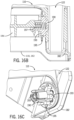
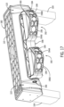
FIGS. 15A-18C depict a top cap of a ladder in accordance with an embodiment of the present disclosure; -
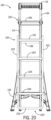
FIGS. 19 and20 are perspective and rear views, respectively, of a ladder in accordance with an embodiment of the present disclosure; -
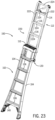
FIGS. 21-23 are various views of the ladder shown inFIGS. 19 and20 in various states; -
FIG. 24 is a perspective view of a ladder in accordance with an embodiment of the present disclosure; -
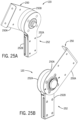
FIGS. 25A and 25B are right and left perspective views of a hinge assembly which may be used with a ladder according to an embodiment of the present disclosure; -
FIG. 26 is a front view of the hinge assembly shown inFIGS. 25A and 25B with a portion made transparent to depict certain components; -
FIG. 27 is an exploded view of the hinge assembly shown inFIGS. 25A and 25B ; -
FIG. 28 is a sectional view of the hinge assembly shown inFIGS. 25A and 25B while in a locked state; -
FIGS. 29-31 are various additional views of the hinge assembly shown inFIGS. 25A and 25B while in a locked state; -
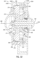
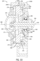
FIGS. 32 and33 are sectional views of the hinge assembly shown inFIGS. 25A and 25B while transitioning from a locked state to and unlocked state; -
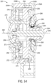
FIG. 34 is a sectional view of the hinge assembly shown inFIGS. 25A and 25B while in an unlocked state; -
FIGS. 35-37 are various additional views of the hinge assembly shown inFIGS. 25A and 25B while in an unlocked state; -
FIG. 38 shows a portion of the hinge assembly according to an embodiment of the present disclosure; -
FIG. 39 is a perspective view of a foot for a ladder having an integrated wall pad according to an embodiment of the disclosure; -
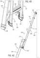
FIG. 40 shows a lower portion of a ladder incorporating the foot shown inFIG. 39 in a stored or collapsed state; -
FIG. 41 shows a lower portion of a ladder incorporating the foot shown inFIG. 39 with the ladder in a deployed, step-ladder configuration; -
FIG. 42 is a side view of a portion of a ladder incorporating the foot shown inFIG. 39 with the ladder in a deployed, straight-ladder configuration; -
FIG. 43 is a perspective view of a portion of a ladder incorporating the foot shown inFIG. 39 with the ladder in a deployed, straight-ladder configuration; -
FIG. 44 is a perspective view of a ladder component according to an embodiment of the present disclosure; -
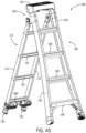
FIG. 45 is a front perspective view of a ladder in a step-ladder configuration with the component shown inFIG. 44 attached to the ladder; -
FIG. 46 is a rear perspective view of the ladder shown inFIG. 45 while in a stored or collapsed condition; -
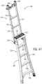
FIG. 47 is a front perspective view of the ladder shown inFIG. 45 while in an extended condition; -
FIGS. 48 and49 are enlarged views of the upper portion of the ladder shown inFIG. 47 ; -
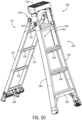
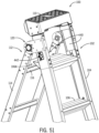
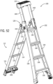
FIG. 50 is a perspective view of a ladder according to another embodiment of the present disclosure; -
FIG. 51 is an enlarged view of an upper portion of the ladder shown inFIG. 50 ; -
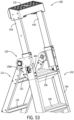
FIG. 52 is a perspective view of the ladder shown inFIG. 50 wherein the top cap is in an extended position according to another embodiment of the present disclosure; -
FIG. 53 is an enlarged view of an upper portion of the ladder shown inFIG. 52 ; -
FIG. 54 is a rear perspective view of an upper portion of a ladder showing a ladder component in accordance with another embodiment of the present disclosure; -
FIGS. 55 and56 are perspective views, andFIG. 57 is a top view, of the ladder and component shown inFIG. 54 while in various states or configurations; -
FIG. 58 is a top perspective view of a foot for a ladder having an integrated wall pad according to an embodiment of the disclosure; -
FIG. 59 is a bottom perspective view of the foot shown inFIG. 58 ; -
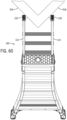
FIG. 60 is a top view of a ladder incorporating the foot shown inFIG. 58 with the ladder in a deployed, straight-ladder configuration against a support exhibiting an exterior comer; -
FIG. 61 is a top view of a ladder incorporating the foot shown inFIG. 58 with the ladder in a deployed, straight-ladder configuration against a support exhibiting an interior corner; -
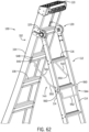
FIG. 62 is a perspective view of a portion of a ladder incorporating a spreader structure with the ladder in a step ladder configuration; -
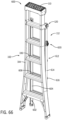
FIG. 63 is a side view of a portion of the ladder shown inFIG. 62 with the ladder in a leaning ladder configuration; -
FIG. 64 is a side perspective view of a portion of the ladder shown inFIG. 62 with the ladder in a straight-ladder configuration; -
FIG. 65 is a perspective view of a ladder according to another embodiment of the present disclosure in a step ladder configuration; -
FIG. 66 is a perspective view of the ladder shown inFIG. 65 in a leaning-ladder configuration; -
FIG. 67 is a perspective view of the ladder shown inFIG. 65 in another state with the rear assembly extended; and -
FIG. 68 is a perspective view of the ladder shown inFIG. 65 in an extended, straight-ladder configuration. - Various embodiments of ladders and ladder components are described herein. The described embodiments are not mutually exclusive of each other. Rather, various features, components or elements of one described embodiment may be used in conjunction with features, components or elements of other described embodiments.
- Referring to
FIGS. 1-4 aladder 100 is shown in accordance with an embodiment of the present disclosure. Theladder 100 includes afirst assembly 102 having a pair of spaced apart rails 104 and a plurality ofrungs 106 extending between and coupled to therails 104. For purposes of convenience, therungs 106 andrails 104 of thefirst assembly 102 may be referred to herein as "front rungs 106" or "front rails 104" respectively. - The
front rungs 106 are spaced apart, substantially parallel to one another, and are configured to be substantially level when theladder 100 is in an orientation of intended use so that therungs 106 may be used as "steps" for a user to ascend theladder 100 as will be appreciated by those of ordinary skill in the art. In various embodiments, the upper surface of therungs 106 may include traction features (e.g., grooves and ridges, grip tape or other anti-slip features) to provide traction to a user while standing on therungs 106. Atop cap 110 may be coupled with the upper portions of thefront rails 104 and configured to support the weight of a user in the event that a user stands on thetop cap 110. The upper surface of thetop cap 110 may also include traction or anti-slip features to provide traction to a user while standing thereon. - The
ladder 100 also includes asecond assembly 112 having a pair of spaced apart rails 114. A plurality ofrungs 116 extend between and are coupled to the spaced apart rails 114. For purposes of convenience, therungs 116 andrails 114 of the second assembly may be referred to herein as "rear rungs 116" and "rear rails 114" respectively. It is noted that the use of the terms "front" and "rear" herein is not to be considered limiting although describing relative positions of the components when theladder 100 is in a step ladder configuration. Rather, use of "front" and "rear" is for purposes of convenience and clarity in describing various components or assemblies of the embodiments of the present disclosure. - The
rear rungs 116 are spaced apart, substantially parallel to one another, and are configured to be substantially level when theladder 100 is in an orientation for intended use so that therear rungs 116 may be used as "steps" for a user to ascend theladder 100. In various embodiments, the upper surface (considering the orientation of the ladder as viewed inFIG. 1 ) of therear rungs 116 may include traction features (e.g., grooves and ridges, grip tape or other anti-slip features) to provide traction to a user while standing on therear rungs 116. Additionally, or alternatively, in some embodiments, therear rungs 116 may include traction features or anti-slip features formed the lower surface thereof (again, as viewed inFIG. 1 ). In some embodiments, thesecond assembly 112 may includesupport structure 117 which may be used, for example, to engage the wall, post, stud or vertical support when theladder 100 is in a straight-ladder or extended state such as shown inFIG. 2 . In other embodiments, thesupport structure 117 may be replaced with another rung or with some other structure such as discussed herein below. - The
second assembly 112 is pivotally coupled with thefirst assembly 102 via a pair of hinge assemblies 120 (sometimes referred to as "hinges" herein for purposes of brevity). In the embodiment shown, thehinges 120 are spaced away from thetop cap 110 along the length of thefront rails 104 of thefirst assembly 102. For example, thehinges 120 may be positioned adjacent therung 106 that is closest to thetop cap 110. In one embodiment, this may be approximately 30.48 cm (12 inches) from the top of thefirst assembly 102. The hinges 120 are configured to selectively lock thefirst assembly 102 and thesecond assembly 112 in one or more desired positions relative to each other. Thus, for example, inFIG. 1 , the first andsecond assemblies rear rails 114 extend at an acute angle relative to thefront rails 104, placing the ladder in a step ladder configuration. - It is noted that, in some embodiments, the
ladder 100 does not include any spreader mechanisms (e.g.., hinged, folding braces or other structures that extend between the first and second assemblies) that are conventionally used to accommodate the folding of the ladder as well as the "locking" of the first andsecond assemblies hinges 120 maintain the desired positioning of the first andsecond assemblies FIG. 1 . - As seen in
FIGS. 2 and3 , thehinges 120 also enable thesecond assembly 112 to selectively rotate relative to thefirst assembly 102 such that therear rails 114 may be positioned to extend at an angle of substantially 180 degrees from the front rails 104. Stated another way, thefront rails 104 andrear rails 114 extend from each other in a generally parallel manner with a significant portion of thesecond assembly 112 extending upwards and beyond thetop cap 110. The hinges 120 may also be configured to lock the first andsecond assemblies ladder 100 is leaned against an appropriate support surface (e.g., a wall or the edge of a roof). - When the
ladder 100 is in a straight ladder configuration, such as shown inFIGS. 2 and3 , portions of therails 114 of thesecond assembly 112 are received by, and abut against one or more surfaces ofchannels 122 that are formed in the rear face of thetop cap 110 such that the rear rails 114 (or at least a portion thereof) nest within thechannels 122. As will be detailed further below, the positioning of a portion of therear rails 114 within thechannels 122 forms a structure that might be referred to as an open-mortise and through-tenon arrangement. This configuration provides strength and stability to the resultant straight ladder, with an overlap of thefront rails 104 andrear rails 114 occurring between thehinges 120 and thechannels 122. - It is noted that with the
second assembly 112 "flipped up" into a position that places theladder 100 in a straight ladder configuration (e.g.,FIGS. 2 and3 ), one of therear rungs 116 may align with the upper surface of thetop cap 110, providing an extended support surface (i.e., the combined surface areas of the upper surface of thetop cap 110 and the tread surface of the adjacent rung 116) on which a user may stand. Additionally, theother rungs 116 of thesecond assembly 112 are spaced similarly to therungs 106 of thefirst assembly 102 so that a user may continue to climb from therungs 106 of thefirst assembly 102, onto thetop cap 110, and on to therungs 116 of thesecond assembly 112 in a continuous and uninterrupted manner, and without a change in spacing from one step to another, as the user ascends and descends theladder 100. - As noted above, the
hinges 120 may be configured to lock when in the position shown inFIGS. 2 and3 , providing a certain amount of structural rigidity between the twoassemblies rear rails 114 may each abut a back surface of theircorresponding channel 122 such that force (e.g., from a user climbing the ladder 100) is transferred through thefirst assembly 102, via thetop cap 110, to the rear rails 114. In addition to the transfer of this type of force, it is noted that lateral forces (e.g., forces extending in a direction along an axis that passes through both front rails 104) may also be distributed through thetop cap 110, through the sidewalls of thechannels 122 to the rear rails 114 (or vice versa), and in combination with the connections provided by thehinges 120, again providing significant strength and stability to theladder 100 when in the configuration shown inFIGS. 2 and3 . - Referring to
FIG. 4 , thesecond assembly 112 may be selectively positioned, relative to the first assembly, in a storage or leaning configuration, wherein therear rails 114 are placed adjacent to, and extend substantially parallel to, the front rails 104. In this configuration, no portion of the second assembly extends upwards beyond the top cap 110 (or otherwise contacts the top cap 110) as occurs in the straight ladder configuration. In this configuration, theladder 100 may be stored in relatively compact space, or it may be used to lean up against a supporting surface or an object (e.g., a wall or a pole), placing the user closer to the supporting surface. As will be discussed in further detail below, a cushion or other resilient and/or non-marking material may be located on a back face of thetop cap 110 to engage with a support surface (e.g., a wall) so that the ladder does not scratch or otherwise mar the support surface. - The
first assembly 102 and thesecond assembly 112 may additionally includefeet rear rails feet feet 132 may also be configured to engage a supporting surface such as a wall when in a straight ladder configuration. - The
feet feet feet U.S. Patent No. 9,016,434 to Moss et al. U.S. Patent Application No. 15,897,995, filed on Feb. 15, 2018 - In some embodiments, the
ladder 100 may include other components including, for example, various bracing members or other structural components. For example, one or more brace members may be used to provide increased strength, rigidity, and/or durability to the ladder. In one example, with reference toFIGS. 1-6 ,brace members 140 may be coupled between the rails (e.g., the front rails 104) and their associated rungs (e.g., the front rungs 106). Such abrace 140 may be coupled to the various members by mechanical fastening, material joining, use of adhesives, or other techniques. In one particular example, the brace may be fastened to one component (e.g., to a rung 106) by way of a mechanical fastener, while being coupled with another component (e.g., to a front rail 104) merely by encircling the component. Examples of some potential braces, along with techniques of coupling braces with associated components, are described inU.S. Patent Application No. 15/952,437, filed on April 13, 2018 - In some embodiments, a mechanism or
assembly 144, configured as a last-step indicator, may be incorporated into or otherwise associated with a lowermost rung or the ladder (e.g., thelowermost rung 106 of the first assembly 102). Theassembly 144 may be configured such that, when a user is descending theladder 100 and places their weight on the lowermost rung, an alert (e.g., a sound, light, or vibrational signal) is provided to the user, indicating that this is the last rung in their descent, and that their next "step down" will be to the supporting surface (e.g., the floor or ground). Some examples of mechanisms or assemblies used as last-step indicators are described inU.S. Patent Application No. 14/849,917, filed on Sept. 10, 2015 - The first and
second assemblies rear rails rungs top cap 110 may be formed of a plastic material and may be molded. In other embodiments, theassemblies 102 and 112 (and their various components) may be formed of a variety of other materials including, for example, other composites, plastics, polymers, metals and metal alloys. - It is noted that, in some embodiments, the
front rails 104 may be tapered, angled or curved such that the lowermost portions of the twofront rails 104 are spaced further from one another than the uppermost portions of the twofront rails 104. In some embodiments, such as best seen inFIG. 5 , thefront rails 104 exhibit a curved geometry in at least a lower portion of the rails, bending outwards from each other. This may be the case even in embodiments where therails 104 are formed of composite materials such as, for example, fiberglass. The curved portion of thefront rails 104 at their lower ends provides a widened base which increases the lateral stability of theladder 100. Additionally, the straight portions, or parallel sections, at the upper ends of thefront rails 104 enable thehinges 120 to be assembled to two parallel components, preventing binding of thehinges 120 when thesecond assembly 112 transitions between its various positions or states. - It is noted that in other embodiments, the first and/or
second assemblies - Referring now to
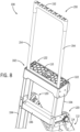
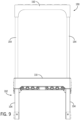
FIGS. 7-10 , in some embodiments, theladder 100 may include a component such as aretractable rail 150 that extends from thetop cap 110 and may assist a user in maintaining their balance and stability while standing on one of theupper rungs 106 of thefirst assembly 102. Therail 150 may include across member 152 coupled between a pair of spaced apartlegs 154. Thecross member 152 may include a surface that generally matches or mirrors the upper surface of the top cap 110 (e.g., in terms of traction or anti-slip features or materials) so as to become substantially integrated with thetop cap 110 when it is in a stored position. Therail 150 is displaceable between a stored position or configuration (seeFIG. 7 ) and an extended or deployed position or configuration (seeFIGS. 8-10 ). In some embodiments, therail 150 may be maintained in an extended position by a locking mechanism (e.g., a spring biased button, a detent mechanism, a latch, etc.). In other embodiments, therail 150 may be maintained in an extended position by way of a frictional force or a biasing force exhibited between, for example, thelegs 154 and adjacent surfaces of thetop cap 110. As seen inFIG. 7 , when therail 150 is in the stored or retracted position, thelegs 154 may extend down through one or more of therungs 106 along the inner surfaces of the front rails 104. In some embodiments, thefront rails 104 of thefirst assembly 102 may be formed as channels (e.g., c-shaped channels), wherein thelegs 154 are positioned within the hollow or recessed portion of the channel, keeping thelegs 154 out of the path of a user's feet as they climb therungs 106 of thefirst assembly 102. - In some embodiments, the feet of one or both of the
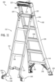
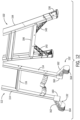
assemblies FIGS. 11-14 , thefeet 132 coupled to the ends of therear rails 114 may each include acoupling portion 160 coupled to an associatedrear rail 114. Thefeet 132 may each further include alateral extension portion 162 extending laterally away from the associatedrear rail 114, and asurface engagement portion 164 that is configured to engage a supporting surface. Thefeet 132 are each independently rotatable about an axis that extends substantially along the length of the associatedrear rail 114, and may each be locked or maintained in a variety of positions by detent mechanisms, push button locks, clamping mechanisms, or a variety of other mechanisms or devices. - Referring to
FIGS. 11 and12 , when the ladder is in a step ladder configuration, thefeet 132 may be positioned relative to therear rails 114 such that thesurface engagement portions 164 are positioned laterally outward from the rear rails 114 (e.g., at 180 degrees) and such that the feet engage a supporting surface (e.g., the ground, a floor or other generally horizontal structure) at a width that is greater than the width of the rear rails 114. In some embodiments, thesurface engagement portions 164 may extend in substantially the same plane as the associatedrear rails 114, maximizing the width at which thesurface engagement portions 164 engage the supporting surface. Thus, for example, in some embodiments, therear rails 114 may exhibit a width of approximately 36.83 cm (14.5 inches) or less (and in some embodiments 33.56 cm (14 inches) or less), while thefeet 132 may be configured to exhibit a width of approximately 45.72 cm to approximately 60.69 cm (18 to approximately 24 inches) or greater, providing substantial stability to theladder 100 when used in a step ladder configuration. - In some embodiments, the
feet 132 may be rotated to a position that is substantially 90 degrees, in either rotational direction, from the position shown inFIGS. 11 and12 . It is noted that in embodiments where therear rails 114 are configured to exhibit a width of 36.83 cm (14.5 inches) or less, that thesecond assembly 112 may be placed between adjacent studs of typical wall construction (prior to sheet rock or other surfaces being installed), enabling a user to get closer to a wall (e.g., thetop cap 110 moves closer to the wall when thesecond assembly 112 is passed through the space between two adjacent studs) providing enhanced access to a desired work location. - The
feet 132 may be rotated to, and locked at, other positions as well. For example, as shown inFIGS. 13 and14 , when the ladder is in a straight ladder configuration, it may be desirable in some circumstances to rotate thefeet 132 such that thesurface engagement portions 164 extend generally inward (generally toward each other) from therear rails 114 but at an angle (e.g., in a direction back toward the first assembly 102) relative to the plane in which therear rails 114 extend. Thesurface engagement portions 164 may thus be configured to generally mimic or function as a v-rung for engagement with a pole (e.g., a power pole, telephone pole, etc.) or other vertical structure when theladder 100 is in a straight ladder configuration. In one embodiment, thefeet 132 may be rotated so that thesurface engagement portions 164 extend at an angle of between approximately 20 degrees and approximately 45 degrees relative to the plane in which therear rails 114 extend. Of course, thefeet 132 may be placed in other angular positions as well. - In some embodiments, the
feet 132 may be configured to be rotated to, and locked at, angular positions such that thesurface engagement portions 164 extend generally outward from the rear rails 114 (away each other) but at an angle (away the first assembly 102) relative to the plane in which therear rails 114 extend such as is shown in dashed lines inFIG. 14 . Thesurface engagement portions 164 may then function as a wall stand-off device, providing increased width of contact with a wall (or gutter, or other supporting structure) when theladder 100 is in a straight ladder configuration. In one embodiment, thefeet 132 may be rotated so that thesurface engagement portions 164 extend at an angle of between approximately 5 degrees and approximately 45 degrees relative to the plane in which therear rails 114 extend. In some embodiments, thefeet 132 may be rotated such that thesurface engagement portions 164 extend directly towards each other (at 0 degrees) to minimize the width of thefeet 132 in certain circumstances, including for storage or transportation. Of course, thefeet 132 may be placed in other angular positions as well. - It is noted that, because the
surface engagement portions 164 may engage a variety of different structures (e.g., ground, poles, walls, etc.), thesurface engagement portions 164 may include a variety of surfaces (e.g., 164A, 164B and 164C) having grooves, ribs, or other traction features formed therein. Thus, for example, afirst surface 164A may be configured to engage poles or other vertical structures when in a straight ladder configuration, asecond surface 164B may be configured to engage gutters or walls when in a straight ladder configuration, and athird surface 164C may be configured to engage a ground surface when in a stepladder configuration. - Referring now to
FIGS. 15A-18C , atop cap 110 may include a variety of features. For example, as previously noted, a pair ofchannels 122 may be formed in a rear portion of thetop cap 110, thechannels 122 being sized and configured to receive portions of therear rails 114 therein when theladder 100 is placed in a straight ladder configuration. When in a straight ladder configuration, a bottom (or innermost)surface 170A of eachchannel 122 may contact asurface 172A of an associated rear rail 114 (see, e.g.,FIGS. 2 and3 ). Additionally, side surfaces 170B and 170C may be configured to provide lateral support by engaging corresponding side surfaces 172B and 172C, respectively, of an associatedrear rail 114. Thus, for example, if a force is applied to theladder 100 in a lateral direction (e.g., as shown bydirectional arrows FIG. 2 ), a minor amount of lateral deflection may occur in the rear rails 114 (and/or front rails 104), wherein the side surfaces 170B and 170C act as stops or abutment members to limit further lateral deflection or displacement of therear rails 114 relative to thefront rails 104 due to the nesting of therear rails 114 within thechannels 122. - As also previously mentioned, a cushion or
pad 180 is positioned along a rear face of thetop cap 110 such that thetop cap 110 may be leaned or pressed against, for example, a wall when used in a leaning configuration. As seen inFIGS. 15A-18C , thetop cap 110 includes afirst body portion 182 that is coupled to thefront rails 104, and a second body portion 184 (which may include a detachable accessory) that is selectively positionable (and lockable) relative to thefirst body portion 182. For example, thesecond body portion 184 may be positioned in a first position such that a surface 186 (on which the cushion or pad 180 may be located) is positioned generally adjacent to therear face 188 of thefirst body portion 182. It is noted that in some embodiments, thesurface 186 and adjacentrear face 188 may be angled relative to each other (e.g., an angle measuring greater than 180 degrees when measuring from thesurface 186 to the rear face 188). In some embodiments, therear face 188 may be angled such that it abuts against a surface of arear rung 116 when in a straight ladder position or configuration, providing enhanced strength and rigidity to theladder 100. In other embodiments, there may be a gap or small space between therear face 188 and the adjacentrear rung 116. - According to the invention, the
second body portion 184 is pivotally coupled with thefirst body portion 182 by way of a pivoting structure such that thesecond body portion 184 rotates to at least a second position relative to thefirst body portion 182. As seen inFIGS. 15B and 15C , a pivoting structure may include a pair of lockingbuttons 190 having keyed or gearedportions 193 configured to engage corresponding openings 195 (e.g., openings that have portions sized and shaped to receive the keyed portions 193) formed in thefirst body portion 182 of thetop cap 110. When thekeyed portions 193 are engaged incorresponding openings 195, as shown inFIGS. 15B and 15C (note thatFIG. 15C depicts thetop cap 110 with thesecond body portion 184 removed for purposes of clarity), thesecond body portion 184 is locked in place and prevented from rotating relative to thefirst body portion 182. However, when the locking buttons are displaced axially along a pivot axis such that thekeyed portions 193 disengage the openings 195 (seeFIGS. 16B and 16C - withFIG. 16C depicting thetop cap 110 with thesecond body portion 184 removed for purposes of clarity), thesecond body portion 184 and lock button may rotate relative to thefirst body portion 182 such as depicted inFIG. 16A . - When the
second body portion 184 is rotated to a second position (e.g., such as shown inFIG. 17 ), and upon alignment of thekeyed portions 193 with corresponding features in theopening 195, thelock buttons 190 may be displaced axially by a biasingmember 197, such as a spring, such that they keyedportions 193 engage theopenings 195 and thesecond portion 184 is locked into place relative to thefirst portion 182 in the second position. - As seen in
FIG. 17 , when thesecond body portion 184 is rotated into a second position, various features of thesecond body portion 184 may protrude outwardly from therear face 188 of thefirst body portion 182. Thesecond body portion 184 includes a pair of protrudingstructures 192 providing a first pair ofangled engagement surfaces angled engagement surfaces channel 198 that is located adjacent to, and in between, the first pair ofengagement surfaces - With the
second body portion 184 selectively locked in the second position by locking buttons 190 (or by other appropriate mechanisms or structures such as detent mechanisms, latches, frictional arrangements, etc.), the first pair ofangled engagement surfaces engagement surfaces pads 199 may be placed on each of the engagement surfaces 194A, 194B, 196A and 196B such as best seen inFIG. 17 . - Referring to
FIG. 18A , when used in a leaning configuration (see, e.g.,FIG. 4 ), theladder 100 may be leaned against anexterior wall corner 200 such that the first pair ofengagement surfaces adjacent walls exterior corner 200, providing balance and stability to theladder 100 and enabling a user to get laterally closer to the wall. - Referring to
FIG. 18B , when used in a leaning configuration, theladder 100 may be leaned against aninterior wall corner 204 such that the second pair ofengagement surfaces adjacent walls interior corner 204, again providing balance and stability to theladder 100 and enabling a user to get laterally closer to the wall. - Further, when used in a leaning configuration the
ladder 100 may be braced against a vertical support structure, such as a stud 208 (e.g., a vertically oriented 2X4, 2X6, etc.) of a framed wall, by positioning thestud 208 within thechannel 198, providing balance and stability to theladder 100 and enabling a user to get laterally closer to the wall. Thus, in some embodiments, thechannel 198 may be configured to exhibit a width between its side walls of approximately 3.81 cm (1.5 inches) or slightly larger (e.g., approximately 3.9687 cm to approximately 4.1275 cm (1.5625 to approximately 1.625 inches)) to provide a sliding fit of a standardized stud within thechannel 198. - The
top cap 110 may also include other features including, for example,openings 210 for placing tools or other components therein (e.g., screwdrivers, handles of hammers, etc.), recesses 212 for holding tools or supplies (e.g., nails or screws), or features for coupling accessories with the top cap. In some embodiments, such features may be formed in thefirst body portion 182, in thesecond body portion 184, or in both. - Referring to
FIG. 19-23 , in some embodiments, theladder 100 may include a selectivelypositionable rail member 220. In one example, therail member 220 may include a pair ofside members 222, with eachside member 222 being rotatably coupled with an associated one of the rear rails 114. Theside members 222 may extend a substantial portion of the length of the rear rails 114. In one embodiment, the cross-members 224 may extend between and be coupled with theside members 222. When therail member 220 is in the position or state shown inFIGS. 19-21 , at least some of the cross-members 224 may be spaced from each other such that they are located adjacent to associatedrear rungs 116. Thesecross-members 224 may serve as "depth extensions" of therear rungs 116, providing increased surface area on which a user may stand. - As seen in
FIG. 22 , therail member 220 may be rotated upwards relative to therear rails 114 such that a substantial portion (e.g., half or more) of therail member 220 extends upward above thetop cap 110. Therail member 220 may be locked in this, or other positions, relative to the first andsecond assemblies 102 and 112 (e.g., by way of detent mechanisms, latches, locking hinges, interference fits with thetop cap 110 or other components, etc.). When locked in the position shown inFIG. 22 , therail member 220 provides a stable device for a user to grasp while they are, for example, standing on thefront rungs 106. This enables a user to more safely stand on higher rungs of the ladder than without such arail member 220. - When the
rail member 220 is positioned in a "stored" position relative to therear rails 114, such as shown inFIGS. 19-21 , theladder 100 may still be placed in other configurations such as a straight ladder or a leaning ladder configuration. For example, as shown inFIG. 23 , therail member 220 may rotate with thesecond assembly 112 relative to thefirst assembly 102, into a straight ladder configuration, where at least some of the cross-members 224 are aligned with therear rungs 116, enabling a user to climb and stand on therear rungs 116, with the cross-members 224 providing increased surface area on which they may stand. - Referring briefly to
FIG. 24 , in other embodiments, arail member 230, similar to that shown and described with respect toFIGS. 19-23 , may be associated with thefirst assembly 102 rather than thesecond assembly 112. For example, therail member 230 may be pivotally or rotatably coupled to thefront rails 104, and selectively rotatable from the position shown inFIG. 24 , to an upright position such that a substantial portion thereof extends upwards and above the top cap (similar to therail member 220 shown inFIG. 22 ). As with the embodiment shown and described with respect toFIGS. 19-23 , therail member 230 may includeside members 232 andcross-members 234 extending between, and coupled to, theside members 232. At least some of the cross-members 234 may be aligned with associatedfront rungs 106, acting as depth extenders and providing an increased surface area on which a user may stand. As with therail member 220 previously described, therail members 230 may be locked into various positions by appropriate mechanisms. - Referring now to
FIGS. 25A-38 , ahinge assembly 120 is shown. Thehinge assembly 120 includes a first mountingleg 250 and a secondmounting leg 252. In some embodiments, the first mountingleg 250 may be configured for fixed coupling with the first assembly 102 (e.g., direct coupling with an associated front rail 104). The secondmounting leg 252 may be configured for fixed coupling with the second assembly (e.g., direct coupling with an associated rear rail 114). As will be described hereinbelow, thefirst leg 250 andsecond leg 252 are selectively rotatable, relative to each other, about anaxis 240, and may be locked in a variety of different positions relative to each other. -
FIG. 27 depicts an exploded view of thehinge assembly 120 and its various parts according to an embodiment of the present disclosure. In one embodiment, thefirst leg 250 may include aplate member 250A and alock ring 250B fixedly coupled therewith. Likewise, thesecond leg 252 may include aplate member 252A and alock ring 252B fixedly coupled therewith. A geared member 256 (e.g., a member having one or more projectingcogs 258 extending from a periphery thereof) and a biasing member, such as aspring 260, are positioned between the two lock rings 250B and 252B. The gearedmember 256 includes ashaft member 262 that extends along therotational axis 240 of thehinge assembly 120 and, in some embodiments, may at least partially extend through an opening in thesecond lock ring 252B. In other embodiments, thesecond lock ring 252B may not have an opening, and theshaft 262 may not extend beyond thesecond lock ring 252B. - A
hinge pin 264 extends through openings in theplates member 256 along therotational axis 240. Anut 266 or other fastener may be coupled with thepin 264 to couple the assembly together. - A detent member or mechanism may be associated with the geared
member 256 to hold the gearedmember 256 in a desired position along theaxis 240 between the twolock rings second lock plate 252B and adjacent the associatedplate member 252A (although other configurations are also contemplated for the location of the spring and associated structures). Anactuating button 270 may have afirst portion 270A located externally of thefirst plate member 250A, and have at least anotherportion 270B thereof (e.g., axial fingers) that extends through theplate member 250A as well as a retainer member 171 (also shown inFIG. 26 ) and is configured for establishing contact with the gearedmember 256. Various fasteners (e.g., bolts, screws, rivets, clips, washers, etc.) may be used to couple the components of the hinge assembly together, in addition to thepin 264 andnut 266. - In operation, the two
legs FIGS. 25A and 25B , or at a variety of other positions. As illustrated inFIGS. 28-31 , when thehinge assembly 120 is in a locked state, the gearedmember 256 is axially positioned such that one or more of itscogs 258 are partially disposed in an associatedrecess 272 of thefirst lock ring 250B and partially disposed within an associatedrecess 274 of thesecond lock ring 252B - the tworecesses cog 258 provides an interference structure, preventing thefirst lock ring 250B and thesecond lock ring 252B from rotating relative to one another about theaxis 240. As seen best inFIG. 28 , when in a locked position, the gearedmember 256 is biased axially against aninner face 276 of thefirst lock ring 250B by the biasingspring 260. The biasingspring 260 may be placed between thesecond lock ring 252B and the gearedmember 256, and in some embodiments, positioned concentrically about theshaft member 262 of the gearedmember 256. - Referring to
FIGS. 32 and33 , when a user desires to unlock thehinge 120 and rotate theleg members button 270 in the axial direction towards the gearedmember 256 as indicated byarrow 280. This force overcomes the biasing force of thespring 260 and effects displacement of thebutton 270, and thus displacement of the gearedmember 256, toward thesecond lock ring 252B. For example, comparingFIG. 32 withFIG. 28 , agap 282 is shown inFIG. 32 between the gearedmember 256 and theinner face 276 of thefirst lock ring 250B. Similarly, thegap 282 is enlarged inFIG. 33 as compared to that shown inFIG. 32 , showing further displacement of the gearedmember 256 along theaxis 240 away from theinner face 276 of the first lock ring along theaxis 240. Additionally, in reviewingFIGS. 32 and33 , one can see theshaft member 262 being displaced along theaxis 240 through anopening 284 of thesecond lock ring 252B and toward thesecond plate member 252A. - Referring to
FIGS. 34-37 , when the gearedmember 256 has become sufficiently displaced along theaxis 240, thecogs 258 become axially displaced and disengaged from therecesses 272 of thefirst lock ring 250B while being further displaced into therecesses 274 of thesecond lock ring 252B. For example, as shown inFIGS. 36 and37 , thecogs 258 may be completely positioned within therecesses 274 of thesecond lock ring 252B whileFIG. 34 shows the gearedmember 256 being axially positioned to contact aninner face 290 of thesecond lock ring 252B. Of course, other configurations are contemplated wherein the cogs are disengaged from therecesses 272 of thefirst lock ring 250B without necessarily abutting any axial surface (e.g., inner face 290) of thesecond lock ring 252B. - When in this position, the
shaft member 262 has become displaced such that a first rampedsection 292 is displaced through theopening 284 of thesecond lock ring 252B and beyond the annular spring 268 (which may be axially held in place by a washer or other structure) which radially contracts about an annular recessedportion 294 of the shaft and abuts ashoulder 296 positioned between the rampedsection 292 and the recessed portion. The annular spring thus holds theshaft member 262 andgear member 256 in the position shown inFIGS. 34-37 (keeping the hinge assembly "unlocked") until action is taken to release theshaft member 262 andgear member 256 from this position as will be described below. It is noted that the configuration of theshaft member 262 and theannular spring 268 acts as a detent or detent-like mechanism in holding the gearedmember 256 in a desired position until a prescribed force is applied to the gear member for its release. In other embodiments, other locking mechanisms, including other detent arrangements, may be used to hold the gearedmember 256 in a desired position during operation of the hinge. - Referring to
FIG. 38 , thefirst lock ring 250B may include a plurality of circumferentially-spaced, radially-inward extendingprotrusions 300 that may each include a pair of ramped orangled surfaces 302. One or more of thecogs 258 of the gearedmember 256 may additionally include chamfers 304 (which may referred to as circumferentially oriented chamfers) formed at or near their radially outermost extents which are positioned and oriented to engage the ramped surfaces 302. When thehinge assembly 120 is in an unlocked state (e.g., seeFIGS. 34-37 ), and theleg members surfaces 302 of theradial protrusions 300 engage with the cogs 258 (e.g., with the chamfered portions 304), pushing the gearedmember 256 axially back towards thefirst lock ring 250B until theshaft member 262 is retracted a sufficient distance to become released from the annular spring 262 (placing the gearedmember 256 in axial position similar to that shown inFIG. 33 ). Upon further rotation of theleg members recesses 272 of thefirst lock ring 250B become aligned with thecogs 258 of the gearedmember 256 and thespring 260 forces the gearedmember 256 axially further towards thefirst lock ring 250B, locking the twoleg members hinge 120 may be repeatedly unlocked, rotated, and locked using a similar sequence of events, enabling theleg members - It is noted that, in other embodiments, other hinge assemblies may be used with the
ladder 100. Other, non-limiting examples of hinges that may be used with ladders described herein is set forth inU.S. Patent Application No. 15/622,343, filed on June 14, 2017 U.S. Provisional Patent Application No. 62/514,348, filed on Jun 2, 2017 - Referring to
FIGS. 39-43 , afoot 132 is shown in accordance with another embodiment of the disclosure. Thefoot 132 may include abody portion 320 having anopening 322 formed therein to receive a portion of a rail (e.g.,rail 114 of the second assembly 112). In one embodiment, theopening 322 may be configured as to receive a rail having a rectangular- or square-shaped profile such as shown inFIG. 39 . In other embodiments, the opening may be configured to receive other profiles or cross-sectional shapes including, for example, rails having a C-shaped or H-shaped cross-sectional profile. - The foot includes a first
surface engaging portion 324, which may be referred to as a horizontal surface engaging portion, and a secondsurface engaging portion 326, which may be referred to as a vertical surface engaging portion. Each of the first and secondsurface engaging portions surface engaging portions surface engaging portion 324 may include a plurality of ribs orridges 328 extending across a width 'W' of the foot 132 (e.g., extending in a direction parallel with, or substantially parallel with, an axis that extends through bothfeet 132 of the ladder 100). Adjacent ridges orribs 328 may define parallel grooves extending therebetween. Thus, when theladder 100 is in a step ladder state (e.g., as shown inFIG. 41 ), the firstsurface engaging portion 324 will assist in resisting sliding or slipping, relative to the ground or other support surface, in a direction that is substantially perpendicular to the length of the ribs orridges 328. It is noted that the general surface geometry of the firstsurface engaging portion 324 may be arcuate, such as shown in the drawings, or may be generally flat or planar, or exhibit some other geometry. - Additionally, in one embodiment, the second
engaging surface 326 may include a plurality of ribs orridges 330 extending along a length 'L' in a direction that is substantially perpendicular to the ribs orridges 328 of the firstsurface engaging portion 324. It is noted that the secondsurface engaging portion 326 may extend the entire height of an adjacentrear wall 346. Stated another way, the secondsurface engaging portion 326 may extend from approximately an upper end of the foot 132 (along a plane where theopening 322 is located) down to the firstsurface engaging portion 324. - The second set of ribs or
ridges 330 may also define generally parallel grooves betweenadjacent ridges 330 and be configured to resist or impede sliding or slipping, relative to a vertical wall or other support surface, in a direction substantially perpendicular to the length of the ribs orridges 330. Thus, when theladder 100 is in a straight ladder configuration (FIGS. 42 and43 ), the secondsurface engaging portion 326 may rest against a wall (or other support structure) and resist sliding "sideways" along the surface of the wall. Of course, other anti-slip features, and other orientations or arrangements of anti-slip features are also contemplated as being formed in the surface engaging portions (e.g., patterns of raised protrusions having round, diamond or other polygonal geometries). - The
body 320 may be defined by spaced apartside walls front wall 344 extending between the side walls and arear wall 346 spaced from thefront wall 344 and extending between the side walls (it being noted that "front" and "rear" are simply used for purposes of convenience in designation of the different walls and that such should not be considered limiting). A thickenedsection 348, which may also be referred to as a cushioned section, is positioned adjacent therear wall 346 of thebody 320. Likewise, a thickened or cushionedsection 350 may be positioned at the bottom of thefoot 132, opposite theopening 322 and below a floor of the body 320 (not shown), which is coupled with at least one of the walls (340, 342, 344, 346) or any combination of the walls, including all of them. The thickened or cushionedportions walls portions entire foot 132 may be formed as a unitary, homogenized component (or a substantially unitary, homogenized component) comprising a non-marking rubberized or elastomer material. The ridges and grooves of thesurface engaging portions portions - The second surface engaging portion 326 (associated with the thickened or cushioned
portion 348 positioned along therear wall 346 of the body 320) may be configured to exhibit a surface oriented at a desired angle relative to the longitudinal length of the rail to which it is coupled. Thus, for example, when theladder 100 is in a straight ladder configuration and placed against a wall or other vertical support surface 360 (as shown inFIG. 42 ), the secondsurface engaging portion 326 may form a projected angle α with respect to arear surface 362 of the associatedrear rail 114. In some embodiments, the angle α may be between approximately 13 degrees and 17 degrees. In some embodiments, the angle α may be between approximately 14 degrees and 16 degrees. In one embodiment, the angle α may be approximately 15 degrees. Stated another way, the secondsurface engaging portion 326 may be angled such that when a ladder is leaned against a vertical support at a desired angle, the surface plane of the secondsurface engaging portion 326 is parallel, or substantially parallel, with thevertical support surface 360. - In some embodiments, the
foot 132 may be coupled to arear rail 114 by fasteners (e.g., rivets, screws, etc.). In other embodiments, thefoot 132 may be coupled with arear rail 114 by adhesives. In other embodiments, thefoot 132 may be coupled with therear rail 114 by way of compression fit, interference fit, or by overmolding techniques. In one embodiment, thefoot 132 may be coupled with arear rail 114 using techniques and constructions describe inU.S. Provisional Patent No. 62/732,997, filed on Sep. 18, 2018 - Referring now to
FIG. 44 , anaccessory 400 is shown in accordance with an embodiment of the present disclosure. The in one embodiment, theaccessory 400 may be configured such as shown inU.S. Design Patent Application No. 29/667,357, filed Oct. 19, 2018 - The
accessory 400 may include a variety of features including, for example, hooks, slots, and/or openings (generally indicated as 402) for placing or attaching tools or other components therein (e.g., screwdrivers, handles of hammers, lanyards attached to power tools, electrical cords, etc.), recesses 404 for holding tools or supplies (e.g., nails or screws), and/or features for coupling accessories with the top cap. In one embodiment, notches may be formed for holding a tablet or a smart phone or other type of communications device. For example, as shown inFIG. 44 , one of the recesses (404A) may exhibit a shape and size to hold a cup or a paint can, but also include anadjacent recess 406 on a first side and one ormore notches 408 aligned with therecess 406, that are collectively and cooperatively sized and shaped for receipt of an electronic tablet or smart phone, enabling the tablet or smart phone to be positioned or propped up in a viewing mode for a user to watch or view (e.g., watch a "how to" video) while standing on the ladder. - The
accessory 400 may include a pair of recesses ornotches 410 formed in the body for receipt of ladder rails (e.g., ladder rails 114 of the second assembly 112) for coupling theaccessory 400 to a ladder. As shown inFIGS. 45-48 , theaccessory 400 may be coupled to the ladder rails 114 of thesecond assembly 112 adjacent thefeet 132 of thesecond assembly 112. In some cases, theaccessory 400 may be positioned adjacent therung 116 that is closest to thefeet 132. For example, theaccessory 400 may be removably coupled with therails 114 of the second assembly 112 (using a removable screw, bolt, or a latching device) and then be used or removed as desired by a user of the ladder. In some cases, theaccessory 400 may be positioned adjacent arung 116 or even take place of such a rung and be effectively fixed to therails 114 of thesecond assembly 112 such that a user could not easily remove theaccessory 400 in a nondestructive manner (e.g., such as by drilling through rivets or other fasteners or by destroying an adhesive or material bond between the accessory and the rails). Thus, when theladder 100 is in a step ladder configuration (FIG. 45 ) or a stored configuration (FIG. 46 ), the accessory is positioned toward the "bottom" of thesecond assembly 112. Additionally, as seen inFIGS. 45 and46 , theaccessory 400 is sized, shaped and positioned such that it doesn't cause interference between thesecond assembly 112 and thefirst assembly 102 when placed in the stored state (FIG. 45 ). - Referring to
FIGS. 47-49 , when theladder 100 is in an extended state, the accessory may be positioned near thefeet 132 adjacent the uppermost rung 116 (e.g., between theuppermost rung 116 and the feet 132). - The
accessory 400 may include a variety of features for engaging a support surface (e.g., a wall, post, or other structure). For example, theaccessory 400 may include a first pair ofangled engagement surfaces engagement surfaces engagement surfaces engagement surface 424A is betweenangled surfaces - When the ladder is used in an extended configuration, the
ladder 100 may be leaned against an exterior wall corner such that the first pair ofengagement surfaces ladder 100 and enabling a user to get laterally closer to the wall. Additionally, when theladder 100 is leaned against an interior wall corner, the second pair ofengagement surfaces ladder 100 and enabling a user to get laterally closer to the wall. Likewise, when theladder 100 is leaned against a flat wall or support structure, thethird engagement surfaces - In some embodiments, the engagement surfaces may be configured with ribs and grooves to provide a traction or gripping surface. In some embodiments, additional cushions or pads may be placed on each of the engagement surfaces. The engagement surfaces may, thus, be configured to provide added traction or stability when engaging support surfaces, as well as be configured to avoid marring or marking the support surface with which they engage.
- Further, a notch or
recess 426 may be positioned in the center of the accessory, between the firstangled engagement surfaces ladder 100 may be braced against a vertical support structure, such as a stud (e.g., a vertically oriented 2X4 or 2X6) of a framed wall, by positioning the stud within the notch orrecess 426, providing balance and stability to theladder 100 and enabling a user to get laterally closer to the wall. Thus, in some embodiments, thechannel 426 may be configured to exhibit a width between its side walls of approximately 3.81 cm (1.5 inches) or slightly larger (e.g., approximately 3.9687 cm to approximately 4.1275 cm (1.5625 to approximately 1.625 inches) to provide a sliding fit of a standardized stud within thechannel 426. - Referring now to
FIGS. 50-53 , aladder 100 is shown in accordance with another embodiment of the disclosure. Theladder 100 may be configured generally similar to other embodiments described herein, but also includes a height-adjustabletop cap 110. Thetop cap 110 is coupled to a pair ofextension members 440. Eachextension member 440 is slidably coupled with an upper portion of an associatedfront rail 104 of thefirst assembly 102. In one embodiment, the slidingmembers 440 may be at least partially disposed within a channel or recess formed by the front rails 104 (e.g., in the hollow of a c-channel from which the rails may be formed). Lockingmechanisms 442 may be used to selectively lock theextension members 440 in desired positions relative to the front rails 104. For example, in one embodiment, the locking mechanisms may include a pin that extends through its associatedfront rail 104 and selectively extends into, and retracts out of, openings or recesses formed in theextension members 440. Thus, thetop cap 110 may be locked in a collapsed or retracted position as shown inFIGS. 50 and51 such that the ladder functions similar to previously described embodiments. However, a user may selectively actuate the lockingmechanisms 442 to release theextension members 440, displace the top cap upwards to an extended position, and then release or re-actuate the lockingmechanisms 442 to selectively lock the top cap in the new extended position as shown inFIGS. 52 and53 . Of course, the top cap may be positioned, and selectively locked, at a variety of additional heights (e.g., partially extended) between the two positions shown inFIGS. 50-53 . - When placed in an extended position, such as shown in
FIGS. 52 and53 , thetop cap 110 may serve as a working surface, or as a stabilizing structure, for a user standing on anupper rung 106 of thefirst assembly 102. It is noted that, as shown inFIGS. 52 and53 , theuppermost rung 106 of thefirst assembly 102 may be configured with increased surface area for a user to stand on. For example, theuppermost rung 106 may include aportion 106A that extends beyond the edges of thefront rails 104 of thefirst assembly 102 and towards thesecond assembly 112. In some embodiments, the increased surface area of thisrung 106, as well as the height-extendedtop cap 110, may provide a more comfortable and/or stable structure to work from. - Referring now to
FIGS. 54-57 , atop cap 110 is shown and described with asecond body portion 460, or accessory, according to another embodiment of the present disclosure. Thetop cap 110 may include afirst body portion 182 that is coupled to the front rails 104 (or to extension members such as previously described), and a second body portion 460 (which may include a detachable accessory) that is selectively positionable (and lockable) relative to thefirst body portion 182. For example, thesecond body portion 460 may be positioned in a first position such that a surface 462 (on which a cushion or pad 464 may be located) is positioned generally adjacent to therear face 188 of thefirst body portion 182. It is noted that in some embodiments, thesurface 462 and adjacentrear face 188 may be angled relative to each other (e.g., an angle measuring greater than 180 degrees when measuring from thesurface 462 to the rear face 188) such as has been described with respect to other embodiments herein. In some embodiments, therear face 188 may be angled such that it abuts against a surface of arear rung 116 when in a straight ladder or extended configuration, providing enhanced strength and rigidity to theladder 100. In other embodiments, there may be a gap or small space between therear face 188 and the adjacentrear rung 116. - In some embodiments, the
second body portion 460 may be pivotally coupled with thefirst body portion 182 by way of a pivoting structure (e.g., such as associated with lockingbuttons 190 previously described herein), such that thesecond body portion 460 may rotate to at least a second position relative to thefirst body portion 182. When thesecond body portion 460 is rotated to a second position (e.g., such as shown inFIG. 55 ), thesecond portion 184 may be locked into place relative to thefirst portion 182. - As seen in
FIG. 55 , when thesecond body portion 460 is rotated into a second position, various features of thesecond body portion 460 may protrude outwardly from therear face 188 of thefirst body portion 182. For example, thesecond body portion 460 may include a pair of protruding bodies orstructures 470 providing a first pair ofangled engagement surfaces angled engagement surfaces channel 476 that is located adjacent to, and in between, the first pair ofengagement surfaces FIG. 57 ). - With the
second body portion 460 selectively locked in the second position by locking buttons 190 (or by other appropriate mechanisms or structures such as detent mechanisms, latches, frictional arrangements, etc.), the first pair ofangled engagement surfaces engagement surfaces - As with previously described embodiments, when used in a leaning configuration, the
ladder 100 may be leaned against an exterior wall corner such that the first pair ofengagement surfaces ladder 100 and enabling a user to get laterally closer to the wall. Additionally, theladder 100 may be leaned against an interior wall corner such that the second pair ofengagement surfaces ladder 100 and enabling a user to get laterally closer to the wall. - Further, when used in a leaning configuration the
ladder 100 may be braced against a vertical support structure, such as a stud or a post or pole (e.g., a vertically oriented 2X4, 2X6, etc.) of a framed wall, by positioning the stud within thechannel 476, providing balance and stability to theladder 100 and enabling a user to get laterally closer to the wall. Thus, in some embodiments, thechannel 476 may be configured to exhibit a width between its side walls of approximately 3.81 cm (1.5 inches) or slightly larger (e.g., approximately 3.9687 cm to approximately 4.1275 cm (1.5625 to approximately 1.625 inches)) to provide a sliding fit of a standardized stud within thechannel 476. - When the
second body portion 460 is in the first position (seeFIG. 54 ), thepad 464 and/orsurface 462 may be abutted against a generally planar support surface to provide stability to theladder 100 while in a leaning configuration. - As further depicted in
FIGS. 56 and 57 , it is additionally noted that the protruding bodies orstructures 470 may be configured as containers, having a substantially hollowinternal space 480 or cavity and aremovable lid 482. In one embodiment, thelid 482 may be coupled with the protrudingstructure 470 by way of ahinge 484. Thus, thesecond body portion 460 may serve multiple functions, including providing a convenient storage space for supplies, tools or other resources that can stay within the container even when theladder 100 is not being used or while its being transported or stored. - Referring to
FIGS. 58-61 afoot 132 is shown in accordance with another embodiment of the disclosure. Thefoot 132 may include abody portion 500 having anopening 502 formed therein to receive a portion of a rail (e.g.,rail 114 of the second assembly 112). In one embodiment, theopening 502 may be configured as to receive a rail having a rectangular- or square-shaped profile. In other embodiments, the opening may be configured to receive other profiles or cross-sectional shapes including, for example, rails having a C-shaped or H-shaped cross-sectional profile. - The
foot 132 includes a firstsurface engaging portion 504, which may be referred to as a horizontal surface engaging portion, a secondsurface engaging portion 506, which may be referred to as a planar vertical surface engaging portion, and a thirdsurface engaging portion 508, which may be referred to as an angular or corner surface engaging portion. Each of the first, second and thirdsurface engaging portions surface engaging portions surface engaging portion 504 may include a plurality of ribs orridges 510 extending across a width 'W' of the body 500 (e.g., extending in a direction parallel with, or substantially parallel with, an axis that extends through bothfeet 132 of the ladder 100). Adjacent ridges orribs 510 may define parallel grooves extending therebetween. Thus, when theladder 100 is in a step ladder state, the firstsurface engaging portion 504 will assist in resisting sliding or slipping, relative to the ground or other support surface, in a direction that is substantially perpendicular to the length of the ribs orridges 510. It is noted that the general surface geometry of the firstsurface engaging portion 504 may be planar (with the peaks of the ridges extending to a common plane), such as shown in the drawings, or may be generally arcuate, or exhibit some other geometry. - Additionally, in one embodiment, the second
engaging surface 506 may include a plurality of ribs orridges 512 extending along a length 'L' in a direction that is substantially perpendicular to the ribs orridges 510 of the firstsurface engaging portion 504. In one embodiment, the secondsurface engaging portion 506 may extend from approximately an upper end of the foot 132 (along a plane where theopening 502 is located) down to the firstsurface engaging portion 504. - The second set of ribs or
ridges 512 may also define generally parallel grooves betweenadjacent ridges 512 and be configured to resist or impede sliding or slipping, relative to a vertical wall or other support surface, in a direction substantially perpendicular to the length of the ribs orridges 512. Thus, when theladder 100 is in a straight ladder configuration (such as previously described with respect toFIGS. 42 and43 hereinabove), the secondsurface engaging portion 506 may rest against a wall (or other support structure) and resist sliding "sideways" along the surface of the wall. Of course, other anti-slip features, and other orientations or arrangements of anti-slip features are also contemplated as being formed in the surface engaging portions (e.g., patterns of raised protrusions having round, diamond or other polygonal geometries). - The third
engaging surface 508 may be oriented generally at an angle relative to the secondengaging surface 506. For example, in one embodiment, the thirdengaging surface 508 may be oriented generally at an angle of approximately 45 degrees relative to the second engaging surface. In one embodiment, the thirdengaging surface 508 may include a plurality of ribs orridges 514 extending along a length in a direction that is substantially parallel to the ribs orridges 512 of the secondsurface engaging portion 504. In one embodiment, the thirdsurface engaging portion 508 may extend from approximately an upper end of the foot 132 (along a plane where theopening 502 is located) down to the firstsurface engaging portion 504. - The third set of ribs or
ridges 514 may also define generally parallel grooves betweenadjacent ridges 514 and be configured to resist or impede sliding or slipping, relative to a vertical wall or other support surface, in a direction substantially perpendicular to the length of the ribs orridges 514. In one embodiment, thefeet 132 may be placed on therear rails 114 of a ladder such that the third engagement surfaces 508 face generally inwardly (toward each other) so that, when the ladder is in a straight ladder configuration, the third engagement surfaces 508 can engage the adjacent walls 516 (or other support structures) that form an exterior 90 degree corner such as shown inFIG. 60 . In another embodiment, thefeet 132 may be placed on therear rails 114 of a ladder such that the third engagement surfaces 508 face generally outwardly (toward each other) so that, when the ladder is in a straight ladder configuration, the third engagement surfaces 508 can engage the adjacent walls 518 (or other support structures) that form an interior 90 degree corner such as shown inFIG. 61 . Thefeet 132 may be removable from therear rails 114 to accommodate a change in engaging interior corners and exterior corners. - In other embodiments, the
feet 132 may include a fourth engagement surface positioned such that thesecond engagement surface 506 is located between thethird engagement surface 508 and the fourth engagement surface. The fourth engagement surface may be configured generally similarly to thethird engagement surface 508 and be generally oriented at an angle of approximately 90 degrees from the third engagement surface such that a single foot may be used to engage flat, vertically planar surfaces (seeFIG 42 ), exterior corners (seeFIG. 60 ) and interior corners (seeFIG. 61 ). - For embodiments having three or four (or more) engagement surfaces, the
foot 132 may be generally configured similar to that which is described above regardingFIGS. 39-42 with respect to materials, wall segments, thickened or cushioned portions, etc. - Referring to
FIGS. 62-64 , aladder 100 is shown having aspreader structure 540. Thespreader structure 540 may include a generally U-shaped bar or hoop having a pair of laterally spacedlegs 542 and an end portion or a connectingleg 544 extending between the laterally spacedlegs 542. Each of the laterally spacedlegs 542 may have anend 546 thereof hingedly or pivotally coupled to thefirst assembly 102 by way of associatedbrackets 548. The spreader structure may include a laterally outward extendingbend 550 formed in each of the laterally spacedlegs 542. The connectingleg 544 may have adiscrete section 552 configured to exhibit a width that is less than a width of the space between the rear rails 114. When theladder 100 is in a step ladder configuration, such as shown inFIG. 62 , thespreader structure 540 extends rearwardly from thefirst assembly 102 and encircles thesecond assembly 112. Thespreader structure 540 serves to reinforce the lockinghinge mechanisms 120 and prevent thesecond assembly 112 from splaying relative to thefirst assembly 102. If thesecond assembly 112 attempts to splay relative to thefirst assembly 102, the connectingportion 544 will catch on a portion of anabutment bracket 560 that protrudes rearwardly from a rear surface of therear rails 114, preventing the spreader structure from sliding further upwards on therear rails 114, thereby preventing the splaying of thesecond assembly 112 relative to thefirst assembly 102 when theladder 100 is in a step ladder configuration. - Thus, with larger ladders (e.g., 8 foot ladders or taller, when in a step ladder configuration), the
spreader structure 540 may provide additional strength and stability to theladder 100. - As seen in
FIG. 63 , when theladder 100 is in a leaning or stored configuration, thespreader structure 540 pivots to collapse against thesecond assembly 112, with thediscrete section 552 of the connectingleg 544 extending between the rear rails 114. Additionally, when theladder 100 is in a straight ladder configuration, as shown inFIG. 64 , thespreader structure 540 pivots upward such thatlateral extending bends 550 pass over the hinge mechanisms 120 (and any associated bracketing). Again thediscrete section 552 of the connectingleg 544 extends between the rear rails 114. Thus, thespreader structure 540 may pivot automatically as theladder 100 transitions from a straight ladder configuration, to a step ladder configuration, and then to a leaning configuration. - Referring now to
FIGS. 65-68 , aladder 600 is shown according to another embodiment of the present disclosure. Theladder 600 is configured generally as described with respect to theladder 100 described hereinabove, including afirst assembly 102 coupled with asecond assembly 112 by way of hinges 120. Theladder 600 may further include atop cap 110 and other features such as described hereinabove. However, thesecond assembly 112 may be configured with aninner rail assembly 602 having a pair ofrails 604 and a plurality ofrungs 606, and anouter rail assembly 612 having a pair ofrails 614 and a plurality ofrungs 616. Theouter assembly 612 is slidably coupled with theinner rail assembly 602. Thus, the inner andouter rail assemblies FIG. 65 (andFIG. 66 ), such that most (if not all) of therungs 606 of theinner assembly 602 and most (if not all) of therungs 616 of theouter assembly 612 are aligned in pairs so as to act as a single "step" when a user stands on therungs - The
outer assembly 612 may be extended from theinner assembly 602, such as shown inFIGS. 67 and68 to adjust the length of thesecond assembly 612. For example, when in a step ladder configuration, thesecond assembly 612 may be extended for use on stairs or some other uneven support surface. Additionally, when in a straight ladder or extended configuration, such as shown inFIG. 68 , thesecond assembly 602 may be extended to reach greater heights. Thesecond assembly 612 may be adjusted to several different heights, with each height corresponding with an increment of adjustment equal to the spacing between adjacent rungs (e.g., betweenadjacent rungs 606 of theinner assembly 602 or betweenadjacent rungs 616 of the outer assembly 612). -
Adjustment mechanisms 620, also referred to as locking mechanisms, may be used to selectively release theouter rail assembly 612 from theinner rail assembly 602 and to selectively lock or maintain the inner andouter rail assemblies U.S. Patent No. 8,186,481, issued May 29, 2012 . - While the invention may be susceptible to various modifications and alternative forms, specific embodiments have been shown by way of example in the drawings and have been described in detail herein. However, it should be understood that the invention is not intended to be limited to the particular forms disclosed. Additionally, features, components and elements of one embodiment may be combined with features, components and elements of other embodiments without limitation. The scope of the present invention is as defined by the following appended claims.
Claims (14)
- A top cap (110) for a ladder (100), the top cap (110) comprising:a first body portion (182) configured for coupling with a pair of spaced apart rails (104) of a ladder (100); anda second body portion (184)(460) pivotally coupled with the first body portion (182), the second body portion (184)(460) being pivotable between a first position and a second position, wherein, when in the second position, the second body presents at least one pair of angled engagement surfaces (194)(196)(472)(474) for engagement with a vertical support structure (202)(206)(516)(518);wherein in the first position the second body portion (184)(460) presents a substantially planar surface (186)(462) for engagement with a planar support surface of a vertical support structure (360) to provide stability to the ladder (100) while in a leaning configuration,characterised in that a cushion (180)(464) is disposed on the substantially planar surface (186)(462).
- The top cap (110) of claim 1, wherein the second body portion (184)(460) is selectively positionable and lockable relative to the first body portion (182).
- The top cap (110) of claim 1, wherein the second body portion (184)(460) includes at least one container (470/480).
- The top cap (110) of claim 3, wherein the at least one container (470/480) includes a lid (482) hingedly coupled with a body of the at least one container (470/480).
- The top cap (110) of any of claims 1-4, wherein the top cap (110) includes a pair of channels (122) formed in the first body portion (182) including a first channel adjacent a first side (122) of the second body portion (184)(460) and a second channel (122) adjacent a second side of the second body portion (184)(460), wherein the pair of channels (122) are configured to receive portions of a second pair of spaced apart rails (114) when the second pair of spaced apart rails are rotated to a position such that they extend upward beyond the top cap (110) and are substantially parallel with the first-defined pair of spaced apart rails (104).
- The top cap (110) of any of claims 1-5, wherein the pair of angled surfaces (194)(472) form a 90 degree interior angle.
- The top cap (110) of any of claims 1-6, wherein the pair of angled surfaces (196)(474) form a 90 degree exterior angle.
- The top cap (110) of claim 7, wherein the second body portion (184)(460) further includes a second pair of angled surfaces (194)(472) forming a 90 degree interior angle.
- The top cap (110) of claim 8, wherein the second body portion (184)(460) further includes a channel (198) disposed between a first protruding structure (192)(470) and a second protruding structure (192)(470).
- The top cap (110) of claim 9, wherein the channel exhibits a width of approximately 3.81 cm to approximately 4.128 cm (approximately 1.5 to approximately 1.625 inches).
- The top cap (110) of any of claims 1-10, wherein the second body portion (184)(460) is pivotally coupled with the first body portion (182) by way of a pivoting structure including a pair of locking buttons (190) having keyed portions (193) configured to engage corresponding openings (195) formed in the first body portion (182).
- The top cap (110) of any of claims claim 1-11, wherein when in the first position, a surface (186)(462) of the second body portion (184)(460) is positioned generally adjacent to a rear face (188) of the first body portion (182).
- A ladder (100) comprising:a first assembly (102) comprising:a pair of spaced apart rails (104),a plurality of rungs (106) extending between and coupled to the pair of spaced apart rails (104),a second assembly (112) comprising:
a second pair of spaced apart rails (114),a pair of hinges (120) pivotally coupling the first assembly (102) with the second assembly (104); andthe top cap (110) of any of claims 1-12. - The ladder (100) of claim 13, wherein the second pair of spaced apart rails (114) are rotatable relative to the pair of spaced apart rails (104) to a position such that they extend upward beyond the top cap (110) and are substantially parallel with the first-defined pair of spaced apart rails (104).
Priority Applications (1)
| Application Number | Priority Date | Filing Date | Title |
|---|---|---|---|
| EP25180555.2A EP4596827A3 (en) | 2018-06-08 | 2019-06-07 | A top cap for a ladder |
Applications Claiming Priority (5)
| Application Number | Priority Date | Filing Date | Title |
|---|---|---|---|
| US201862682673P | 2018-06-08 | 2018-06-08 | |
| US201862732997P | 2018-09-18 | 2018-09-18 | |
| US201962834076P | 2019-04-15 | 2019-04-15 | |
| EP19814793.6A EP3810885B1 (en) | 2018-06-08 | 2019-06-07 | Combination ladders, ladder components and related methods |
| PCT/US2019/036172 WO2019237077A1 (en) | 2018-06-08 | 2019-06-07 | Combination ladders, ladder components and related methods |
Related Parent Applications (2)
| Application Number | Title | Priority Date | Filing Date |
|---|---|---|---|
| EP19814793.6A Division EP3810885B1 (en) | 2018-06-08 | 2019-06-07 | Combination ladders, ladder components and related methods |
| EP19814793.6A Division-Into EP3810885B1 (en) | 2018-06-08 | 2019-06-07 | Combination ladders, ladder components and related methods |
Related Child Applications (2)
| Application Number | Title | Priority Date | Filing Date |
|---|---|---|---|
| EP25180555.2A Division EP4596827A3 (en) | 2018-06-08 | 2019-06-07 | A top cap for a ladder |
| EP25180555.2A Division-Into EP4596827A3 (en) | 2018-06-08 | 2019-06-07 | A top cap for a ladder |
Publications (3)
| Publication Number | Publication Date |
|---|---|
| EP4239157A2 EP4239157A2 (en) | 2023-09-06 |
| EP4239157A3 EP4239157A3 (en) | 2023-10-25 |
| EP4239157B1 true EP4239157B1 (en) | 2025-07-09 |
Family
ID=68764675
Family Applications (3)
| Application Number | Title | Priority Date | Filing Date |
|---|---|---|---|
| EP19814793.6A Active EP3810885B1 (en) | 2018-06-08 | 2019-06-07 | Combination ladders, ladder components and related methods |
| EP25180555.2A Pending EP4596827A3 (en) | 2018-06-08 | 2019-06-07 | A top cap for a ladder |
| EP23179459.5A Active EP4239157B1 (en) | 2018-06-08 | 2019-06-07 | A top cap for a ladder |
Family Applications Before (2)
| Application Number | Title | Priority Date | Filing Date |
|---|---|---|---|
| EP19814793.6A Active EP3810885B1 (en) | 2018-06-08 | 2019-06-07 | Combination ladders, ladder components and related methods |
| EP25180555.2A Pending EP4596827A3 (en) | 2018-06-08 | 2019-06-07 | A top cap for a ladder |
Country Status (7)
| Country | Link |
|---|---|
| US (7) | US12601222B2 (en) |
| EP (3) | EP3810885B1 (en) |
| CN (2) | CN112368458A (en) |
| AU (3) | AU2019282832B2 (en) |
| CA (2) | CA3101490C (en) |
| MX (7) | MX2020013128A (en) |
| WO (1) | WO2019237077A1 (en) |
Families Citing this family (27)
| Publication number | Priority date | Publication date | Assignee | Title |
|---|---|---|---|---|
| DE102016123232A1 (en) * | 2016-12-01 | 2018-06-07 | Wilhelm Layher Verwaltungs-Gmbh | Handrail for scaffolding structures |
| CN112368458A (en) | 2018-06-08 | 2021-02-12 | 伟英企业有限公司 | Combination ladders, ladder sections and related methods |
| US11505994B2 (en) * | 2018-10-16 | 2022-11-22 | Tricam Industries, Inc. | Top cap for multi-position ladder |
| USD935054S1 (en) | 2018-10-19 | 2021-11-02 | Little Giant Ladder Systems, Llc | Ladder |
| USD943772S1 (en) | 2018-10-19 | 2022-02-15 | Little Giant Ladder Systems, Llc | Flip-up ladder |
| WO2020154675A1 (en) | 2019-01-25 | 2020-07-30 | Wing Enterprises, Incorporated | Foot for ladders, ladders incorporating same and related methods |
| USD912848S1 (en) | 2019-02-08 | 2021-03-09 | Little Giant Ladder Systems, Llc | Ladder accessory |
| USD911555S1 (en) | 2019-02-08 | 2021-02-23 | Little Giant Ladder Systems, Llc | Top cap for a ladder |
| MX2022003158A (en) | 2019-09-18 | 2022-06-29 | Werner Co | Step ladder pivot and lock mechanism. |
| US12529263B2 (en) * | 2020-01-20 | 2026-01-20 | Little Giant Ladder Systems, Llc | Ladders and ladder rungs |
| WO2021168242A1 (en) | 2020-02-20 | 2021-08-26 | Little Giant Ladder Systems, Llc | Ladders and hinge for ladders |
| CN111377036A (en) * | 2020-04-17 | 2020-07-07 | 中船黄埔文冲船舶有限公司 | Portable flexible splicing ladder |
| US20210396077A1 (en) * | 2020-06-17 | 2021-12-23 | Deltroninc Innovations LLC | Safety ladder |
| AU2021205029B2 (en) * | 2020-07-22 | 2023-04-13 | Werner Co. | Multi-Position Ladder, Method of Using and Method of Making a Multi-Position Ladder |
| CA3126529A1 (en) | 2020-07-30 | 2022-01-30 | Werner Co. | Climbing product having an extendable section lock assembly, and methods for using and producing a climbing product |
| WO2022076568A1 (en) | 2020-10-06 | 2022-04-14 | Little Giant Ladder Systems, Llc | Top cap and accessory tray for ladders and ladders incorporating same |
| US20220195801A1 (en) * | 2020-12-22 | 2022-06-23 | Spartner Group, Inc. | Rotatable top tray on a stepping structure |
| US12523096B2 (en) | 2021-02-01 | 2026-01-13 | Little Giant Ladder Systems, Llc | Top cap for articulating ladder |
| CL2022001904A1 (en) * | 2021-07-14 | 2023-01-20 | Anibal Enrique Schurter Encinas | harvest ladder |
| USD987118S1 (en) * | 2021-07-20 | 2023-05-23 | Kroeger Marine Construction, Inc. | Ladder assembly |
| NL2029224B1 (en) * | 2021-09-22 | 2023-03-29 | Lampe Holding Bv | Portable ladder with a stand off device |
| CN114233171A (en) * | 2022-01-20 | 2022-03-25 | 天津市金锚家居用品有限公司 | foldable ladder |
| USD1056249S1 (en) * | 2022-01-20 | 2024-12-31 | Tianjin Jinmao Houseware Products Co., Ltd | Folding ladder |
| CN119183494A (en) * | 2022-05-27 | 2024-12-24 | 小巨人梯具系统有限公司 | Multifunction button for ladder adjustment |
| US20240352792A1 (en) * | 2023-04-18 | 2024-10-24 | Nicolas Ramirez | Ladder and entertainment combination system |
| USD1091868S1 (en) * | 2023-11-04 | 2025-09-02 | Jiaxing Explorer Metal Products Co., Ltd. | Ladder |
| USD1031090S1 (en) * | 2023-11-15 | 2024-06-11 | Jiaxing Explorer Metal Products Co., Ltd. | Ladder |
Family Cites Families (147)
| Publication number | Priority date | Publication date | Assignee | Title |
|---|---|---|---|---|
| US579263A (en) | 1897-03-23 | Extension step-ladder | ||
| US507784A (en) * | 1893-10-31 | Ladder | ||
| US597685A (en) | 1898-01-18 | Corset-clamp | ||
| US214377A (en) * | 1879-04-15 | Improvement in step-ladders | ||
| GB189923045A (en) | 1899-11-18 | 1899-12-30 | Victor Forir | Improvements in Folding Ladders and Scaffolding. |
| US719450A (en) * | 1902-05-08 | 1903-02-03 | Harry C Heermans | Extension step-ladder. |
| US912409A (en) | 1908-03-14 | 1909-02-16 | Purl C Plasterer | Combination extension and step ladder. |
| US964324A (en) | 1910-04-29 | 1910-07-12 | Charles W Spaulding | Extension step-ladder. |
| US1024380A (en) * | 1910-12-08 | 1912-04-23 | Paul E Vierheller | Ladder. |
| US1100823A (en) | 1913-09-15 | 1914-06-23 | James Robertson Gordon | Collapsible extension-ladder. |
| US1141950A (en) | 1914-03-13 | 1915-06-08 | Ernest Chas Dickinson | Ladder. |
| US1148882A (en) * | 1914-03-21 | 1915-08-03 | Milton M Wood | Convertible ladder. |
| GB191418109A (en) | 1914-07-31 | 1914-12-24 | Robert Douglas | Improvements in Step Ladders and Appliances for Adapting the same for use on Roofs and Inclined Surfaces. |
| GB191518109A (en) | 1915-12-29 | 1916-12-29 | Mark Thomas Graham | A Combined Hand Knife and Golf Club Cleaner or Polisher, and Knife Sharpener. |
| US1284275A (en) | 1917-10-03 | 1918-11-12 | Peter Erickson | Ladder. |
| US1587383A (en) * | 1924-09-22 | 1926-06-01 | Kennett Charles Edward | Convertible ladder |
| US1894489A (en) * | 1928-06-08 | 1933-01-17 | Kito Hirose | Folding stool-ladder |
| US1944792A (en) * | 1933-05-04 | 1934-01-23 | Eli M House | Ladder |
| US1984655A (en) | 1933-12-13 | 1934-12-18 | Rassmussen Martin | Stepladder |
| US2316939A (en) * | 1940-12-03 | 1943-04-20 | David S Garber | Ladder |
| US2639853A (en) * | 1947-12-05 | 1953-05-26 | Robert E Pierce | Ladder structure |
| US2727671A (en) * | 1953-03-25 | 1955-12-20 | Modern Ladders Inc | Ladder construction |
| US2899008A (en) * | 1955-09-21 | 1959-08-11 | White Metal Rolling & Stamping | Multi-way ladder |
| US2982373A (en) * | 1958-11-17 | 1961-05-02 | Hopfeld Henry | Method and device for replacing rungs on a ladder |
| US3715012A (en) * | 1971-09-27 | 1973-02-06 | A Perry | Safety ladder brace |
| JPS5342040B2 (en) | 1973-09-20 | 1978-11-08 | ||
| US3987993A (en) | 1975-12-22 | 1976-10-26 | Hopkins Jeffrey E | Paint can support and brush receptacle |
| JPS5715360Y2 (en) | 1976-09-16 | 1982-03-30 | ||
| US4182431A (en) * | 1978-03-13 | 1980-01-08 | Little Giant Industries Inc. | Combination extension and step ladder rungs therefor |
| US4155422A (en) * | 1978-07-03 | 1979-05-22 | White Metal Rolling & Stamping Corp. | Combination step, stair well and extension ladders |
| US4236603A (en) | 1978-11-09 | 1980-12-02 | Talley Charles D | Ladder leveling device |
| US4210224A (en) * | 1979-01-05 | 1980-07-01 | Kummerlin Nikolaus A | Longitudinally variable ladder |
| US4284171A (en) | 1979-02-12 | 1981-08-18 | Graham Owen | Convertible ladder |
| US4403373A (en) * | 1980-02-15 | 1983-09-13 | Kuemmerlin Walter | Hinge fitting for foldable ladders |
| US4376470A (en) * | 1980-11-06 | 1983-03-15 | Little Giant Industries, Inc. | Fiberglass ladder |
| US4371055A (en) * | 1980-11-07 | 1983-02-01 | Little Giant Industries, Inc. | Method of manufacturing a fiberglass ladder |
| JPS603279Y2 (en) | 1981-04-30 | 1985-01-29 | 長谷川工業株式会社 | End fittings for foldable objects |
| US4407045A (en) * | 1981-12-21 | 1983-10-04 | Boothe Leland H | Ladder hinge and multi-position locking mechanism therefor |
| US4566150A (en) | 1981-12-21 | 1986-01-28 | Little Giant Industries, Inc. | Ladder hinge and multi-position locking mechanism therefor |
| US4415062A (en) * | 1982-09-29 | 1983-11-15 | Western Electric Company, Incorporated | Ladder foot |
| GB2152125B (en) | 1983-12-23 | 1987-07-29 | Alinco Inc | Foldable ladder |
| US4560030A (en) | 1984-05-04 | 1985-12-24 | Metarplastic S.P.A. | Folding ladder |
| US4697305A (en) * | 1985-02-14 | 1987-10-06 | Harold R. Wing | Release mechanism for locking hinge for multi-positioned ladder |
| US4593790A (en) * | 1985-04-17 | 1986-06-10 | Brewer James S | Convertible ladder stabilizer |
| KR890003205Y1 (en) * | 1986-03-04 | 1989-05-17 | 주식회사 우경제작소 | Assembly ladder hinge |
| JPS62173500U (en) | 1986-04-23 | 1987-11-04 | ||
| US4666327A (en) * | 1986-09-22 | 1987-05-19 | George Su | Joint for foldable aluminum ladders |
| USD310884S (en) | 1987-09-24 | 1990-09-25 | R. D. Werner Co., Inc. | Cover for tops of ladders |
| US5573081A (en) | 1987-09-24 | 1996-11-12 | Werner Co. | Ladder top with bail recess |
| USD340773S (en) | 1990-01-26 | 1993-10-26 | R. D. Werner Co., Inc. | Ladder top |
| US5062179A (en) | 1991-03-11 | 1991-11-05 | Huang Ming Tai | Handle assembly for doll carriages |
| FR2674014B1 (en) | 1991-03-12 | 1993-05-28 | Valeo Thermique Moteur Sa | HEAT EXCHANGER WITH CONNECTED WATER BOXES FOR MOTOR VEHICLES. |
| US5279387A (en) * | 1991-09-25 | 1994-01-18 | Emerson Electric Co. | Articulated ladder assembly |
| US5850894A (en) * | 1992-06-16 | 1998-12-22 | Busenhart; Edwin | Ladder, kit, and positioning support for ladder |
| JPH0645096U (en) | 1992-11-25 | 1994-06-14 | 株式会社アミツ | Ladder and stepladder |
| WO1994029561A2 (en) * | 1993-06-15 | 1994-12-22 | Edwin Busenhart | Ladder with support, fastening device, support and kit for building light ladders |
| US5511285A (en) * | 1994-04-19 | 1996-04-30 | Bush; John B. | Ladder handle assembly |
| USD388883S (en) * | 1994-08-26 | 1998-01-06 | Thivierge Gary R | Ladder platform |
| FR2745805B1 (en) | 1996-03-11 | 1998-05-22 | Monomatic Sa | CONTINUOUS COILING MACHINE COMPRISING AT LEAST ONE MEANS OF CONDUCTING TWO TWIN OR SIMULTANEOUSLY COAXIAL COILS |
| KR200146389Y1 (en) | 1996-10-26 | 1999-06-15 | 황성규 | A button for folding ladder |
| US5785447A (en) | 1996-11-21 | 1998-07-28 | Miracle Recreation Equipment Co. | Connector for structural apparatus |
| DE29703876U1 (en) | 1997-03-04 | 1998-07-02 | Krause-Werk GmbH & Co KG, 36304 Alsfeld | Extension ladder |
| US5937968A (en) | 1998-08-13 | 1999-08-17 | Cosco, Inc. | Step stool |
| US6095466A (en) | 1998-09-29 | 2000-08-01 | Sener; James | Modular support assembly for retaining accessory adaptors on a structural member |
| US6443260B1 (en) * | 1999-12-29 | 2002-09-03 | Ladder Mate Corporation | Step ladder tray |
| EP1182322B1 (en) * | 2000-08-14 | 2006-11-15 | Tom Yeh | Hinge on ladder |
| US6575652B2 (en) | 2001-01-16 | 2003-06-10 | Kurt F. Krauss | Structural couplings and system |
| US6711780B2 (en) * | 2001-08-22 | 2004-03-30 | Sinclair Worldwide, Inc. | Hinge for collapsible ladders |
| US6857503B2 (en) * | 2002-02-07 | 2005-02-22 | Tricam Industries, Inc. | Convertible ladder |
| US6866117B2 (en) * | 2002-04-05 | 2005-03-15 | Wing Enterprises, Inc. | Light weight ladder systems and methods |
| US7424933B2 (en) | 2002-05-28 | 2008-09-16 | Norman Miller | Ladder assemblies |
| US7032711B1 (en) * | 2003-10-28 | 2006-04-25 | Ladder Mate Corporation | Accessory tray for stepladders |
| US7140072B2 (en) * | 2003-11-11 | 2006-11-28 | Cosco Management, Inc. | Lockable ladder hinge |
| US7516817B2 (en) | 2004-01-23 | 2009-04-14 | Werner Co. | Ladder with knee brace and method |
| US7093321B2 (en) * | 2004-06-07 | 2006-08-22 | Cosco Management, Inc. | Lockable hinge |
| US20050274571A1 (en) | 2004-06-11 | 2005-12-15 | Dennis Simpson | Convertible fiberglass ladder |
| US7837010B2 (en) | 2004-09-21 | 2010-11-23 | Werner Co. | Combo brace rail shield |
| US8210313B2 (en) | 2006-02-03 | 2012-07-03 | Werner Co. | Pipe tradesman's ladder top and method |
| US7886872B2 (en) | 2006-02-21 | 2011-02-15 | Werner Co. | Electrician's ladder and method |
| USD576290S1 (en) | 2006-05-09 | 2008-09-02 | Cosco Management, Inc. | Step ladder |
| US7575097B2 (en) | 2006-07-20 | 2009-08-18 | Sheridan Vincent J | Ladder attachment |
| USD549356S1 (en) | 2006-07-28 | 2007-08-21 | Louisville Ladder Group Llc | Ladder top |
| US20080083583A1 (en) * | 2006-10-09 | 2008-04-10 | Louisville Ladder Group Llc | Ladder top for supporting a ladder against flat and non-flat surfaces |
| US7753170B1 (en) | 2006-10-09 | 2010-07-13 | Louisville Ladder Inc. | Ladder top for retaining a ladder against extrinsic surfaces |
| US20080107529A1 (en) | 2006-11-02 | 2008-05-08 | Hunter Fan Company | Fan blade connector component with skeleton and method of manufacturing such |
| US8016076B2 (en) | 2006-12-22 | 2011-09-13 | Werner Co. | Flip ladder with tray and method |
| US9097063B2 (en) | 2006-12-22 | 2015-08-04 | Werner Co. | Flip ladder with tray and method |
| USD576291S1 (en) | 2007-05-03 | 2008-09-02 | Werner Co. | Step stool |
| NZ587730A (en) | 2008-03-07 | 2013-01-25 | Wing Entpr Inc | Ladders with locking, spreading, or holding mechanisms, and ladder components and related methods |
| EP2267267A1 (en) | 2008-04-24 | 2010-12-29 | Luhao Leng | A lambdoidal ladder |
| USD597685S1 (en) | 2008-06-09 | 2009-08-04 | Louisville Ladder Inc. | Ladder top |
| US20100200331A1 (en) | 2009-02-07 | 2010-08-12 | Gregory Quinten Hager | Toolshelf for extension ladder |
| US8701831B2 (en) | 2009-03-03 | 2014-04-22 | Wing Enterprises, Inc. | Stepladders and related methods |
| US8251180B1 (en) * | 2010-06-22 | 2012-08-28 | Paige Michael J | Ladder stabilizer apparatus |
| US20120097481A1 (en) * | 2010-10-20 | 2012-04-26 | Cam-K Llc | Ladder attachment |
| WO2012115963A2 (en) | 2011-02-22 | 2012-08-30 | Wing Enterprises, Incorporated | Ladders, ladder components and related methods |
| US9109395B2 (en) * | 2012-06-06 | 2015-08-18 | Raymond Reitz | Corner ladder stabilizer apparatus |
| US8807277B1 (en) | 2013-05-17 | 2014-08-19 | Louisville Ladder Inc. | Shoe bracket assembly for attachment to a bottom of a rail of ladder |
| US10597941B2 (en) | 2013-09-27 | 2020-03-24 | Wing Enterprises, Incorporated | Step ladders, components for step ladders and related methods |
| US9194407B1 (en) | 2014-02-21 | 2015-11-24 | Cuda's Customs, LLC | Universal clamps |
| US10648234B2 (en) | 2014-03-10 | 2020-05-12 | Tricam Industries, Inc. | Step ladder |
| WO2015135037A1 (en) | 2014-03-12 | 2015-09-17 | BASKA, Dr Meenakshi | Improved laryngeal mask |
| USD766461S1 (en) | 2014-09-04 | 2016-09-13 | Wing Enterprises, Inc. | Ladder |
| USD766462S1 (en) | 2014-09-04 | 2016-09-13 | Wing Enterprises, Inc. | Ladder |
| USD766463S1 (en) | 2014-09-04 | 2016-09-13 | Wing Enterprises, Inc. | Top cap for ladder |
| WO2016040648A1 (en) | 2014-09-12 | 2016-03-17 | Wing Enterprises, Incorporated | Ladders, rung assemblies for ladders and related methods |
| USD840055S1 (en) | 2015-02-09 | 2019-02-05 | Tricam Industries, Inc. | Step ladder |
| USD764073S1 (en) | 2015-02-13 | 2016-08-16 | Ningbo Xingfu Tools Co., Ltd. | Working ladder |
| US10138680B2 (en) | 2015-05-26 | 2018-11-27 | Tricam Industries, Inc. | Hinged tray for ladder or step stool |
| US10450799B2 (en) * | 2015-11-05 | 2019-10-22 | Workstation Integrated, Llc | Attachable platform |
| WO2017087082A1 (en) * | 2015-11-16 | 2017-05-26 | Ladder Mfs Llc | Multifunction ladder stabilizer |
| US10030448B2 (en) | 2015-11-26 | 2018-07-24 | Terry James Miller | Ladder stabilization apparatus with adjustable bracing members for use on inside and outside corners of a structure |
| US9840848B2 (en) | 2016-01-25 | 2017-12-12 | Laitram, L.L.C. | Handrail mounting assembly |
| USD819834S1 (en) | 2016-02-10 | 2018-06-05 | Hailo-Werk Rudolf Loh Gmbh & Co. Kg | Universal tray |
| DE202016100719U1 (en) | 2016-02-12 | 2017-05-15 | Hailo-Werk Rudolf Loh Gmbh & Co. Kg | Tray for a ladder and ladder with this tray |
| EP3423664B1 (en) | 2016-03-04 | 2021-08-25 | Little Giant Ladder Systems, LLC | Adjustment mechanisms, ladders incorporating same and related methods |
| CN205591813U (en) * | 2016-03-14 | 2016-09-21 | 厦门新技术集成有限公司 | Extension ladder |
| EP3290630A1 (en) * | 2016-04-14 | 2018-03-07 | Werner Co. | Hybrid stepladder and method |
| CN109154172B (en) | 2016-06-14 | 2021-03-09 | 伟英企业有限公司 | Ladders, ladder hinges, and related methods |
| US20180002982A1 (en) * | 2016-06-30 | 2018-01-04 | Dressel Designs, Llc | Ladder |
| CN206636475U (en) | 2016-11-22 | 2017-11-14 | 金乡县金地电力有限责任公司 | The power construction double ladders of Multifunctional repairing |
| US11131142B2 (en) | 2016-12-20 | 2021-09-28 | Werner Co. | Ladder, overmolded foot and method |
| US10612305B2 (en) | 2016-12-30 | 2020-04-07 | Werner Co. | Ladder, Top and Method |
| USD835807S1 (en) * | 2016-12-30 | 2018-12-11 | Tek Lentine | Ladder top |
| US10590703B2 (en) * | 2016-12-30 | 2020-03-17 | Werner Co. | Ladder, top and method |
| US20180274296A1 (en) | 2017-03-21 | 2018-09-27 | Tricam Industries, Inc. | Adjustable hinge for a multi-position ladder |
| WO2018152318A1 (en) | 2017-02-16 | 2018-08-23 | Wing Enterprises, Incorporated | Ladders, foot mechanisms for ladders, and related methods |
| CN107178303A (en) | 2017-03-03 | 2017-09-19 | 厦门新技术集成有限公司 | The double ladder that a kind of convertible vertical ladder is used |
| US10871031B1 (en) * | 2017-03-13 | 2020-12-22 | Wing Enterprises, Incorporated | Methods of fabricating composite articles and related articles and structures |
| WO2018191623A1 (en) | 2017-04-13 | 2018-10-18 | Cook Benjamin L | Braces for ladders, ladders incorporating same and related methods |
| US10532827B2 (en) * | 2017-05-31 | 2020-01-14 | Federal Express Corporation | Modular staircase |
| WO2018223059A1 (en) | 2017-06-02 | 2018-12-06 | Russell Brian B | Ladder hinge and ladders incorporating same |
| US11933106B2 (en) | 2018-01-23 | 2024-03-19 | Werner Co. | Ladder, foot and method |
| US11280133B2 (en) * | 2018-01-30 | 2022-03-22 | Werner Co. | 7000 series aluminum alloy ladder, multipurpose ladder and method |
| CN112368458A (en) | 2018-06-08 | 2021-02-12 | 伟英企业有限公司 | Combination ladders, ladder sections and related methods |
| USD921224S1 (en) | 2018-07-20 | 2021-06-01 | Little Giant Ladder Systems, Llc | Ladder |
| USD920541S1 (en) | 2018-07-20 | 2021-05-25 | Little Giant Ladder Systems, Llc | Ladder |
| US11187039B2 (en) * | 2018-08-09 | 2021-11-30 | Louisville Ladder Inc. | Configurable ladder system and method |
| USD885607S1 (en) | 2018-10-19 | 2020-05-26 | Wing Enterprises, Incorporated | Accessory for ladder |
| USD912847S1 (en) | 2018-10-19 | 2021-03-09 | Little Giant Ladder Systems, Llc | Top cap for ladder |
| USD943772S1 (en) | 2018-10-19 | 2022-02-15 | Little Giant Ladder Systems, Llc | Flip-up ladder |
| USD935054S1 (en) | 2018-10-19 | 2021-11-02 | Little Giant Ladder Systems, Llc | Ladder |
| USD911555S1 (en) | 2019-02-08 | 2021-02-23 | Little Giant Ladder Systems, Llc | Top cap for a ladder |
| USD912848S1 (en) | 2019-02-08 | 2021-03-09 | Little Giant Ladder Systems, Llc | Ladder accessory |
| US12084917B2 (en) * | 2020-02-12 | 2024-09-10 | Tricam Industries, Inc. | Stepladder tray |
| WO2021168242A1 (en) * | 2020-02-20 | 2021-08-26 | Little Giant Ladder Systems, Llc | Ladders and hinge for ladders |
| CN114233171A (en) * | 2022-01-20 | 2022-03-25 | 天津市金锚家居用品有限公司 | foldable ladder |
-
2019
- 2019-06-07 CN CN201980038098.0A patent/CN112368458A/en active Pending
- 2019-06-07 US US16/435,204 patent/US12601222B2/en active Active
- 2019-06-07 MX MX2020013128A patent/MX2020013128A/en unknown
- 2019-06-07 AU AU2019282832A patent/AU2019282832B2/en active Active
- 2019-06-07 CA CA3101490A patent/CA3101490C/en active Active
- 2019-06-07 US US16/435,232 patent/US11441356B2/en active Active
- 2019-06-07 CA CA3291256A patent/CA3291256A1/en active Pending
- 2019-06-07 CN CN202510535474.4A patent/CN120486902A/en active Pending
- 2019-06-07 WO PCT/US2019/036172 patent/WO2019237077A1/en not_active Ceased
- 2019-06-07 EP EP19814793.6A patent/EP3810885B1/en active Active
- 2019-06-07 EP EP25180555.2A patent/EP4596827A3/en active Pending
- 2019-06-07 US US16/435,183 patent/US12065882B2/en active Active
- 2019-06-07 EP EP23179459.5A patent/EP4239157B1/en active Active
-
2020
- 2020-12-03 MX MX2024011157A patent/MX2024011157A/en unknown
- 2020-12-03 MX MX2024011158A patent/MX2024011158A/en unknown
- 2020-12-03 MX MX2024011159A patent/MX2024011159A/en unknown
- 2020-12-03 MX MX2025008598A patent/MX2025008598A/en unknown
- 2020-12-03 MX MX2024011160A patent/MX2024011160A/en unknown
- 2020-12-03 MX MX2024011161A patent/MX2024011161A/en unknown
-
2022
- 2022-06-24 US US17/848,823 patent/US12152445B2/en active Active
-
2024
- 2024-09-09 US US18/828,597 patent/US20240426176A1/en active Pending
-
2025
- 2025-01-16 US US19/025,538 patent/US20250154829A1/en active Pending
- 2025-04-25 US US19/190,118 patent/US12529264B2/en active Active
- 2025-05-23 AU AU2025203834A patent/AU2025203834B2/en active Active
- 2025-07-30 AU AU2025210796A patent/AU2025210796A1/en active Pending
Also Published As
Similar Documents
| Publication | Publication Date | Title |
|---|---|---|
| EP3810885B1 (en) | Combination ladders, ladder components and related methods | |
| US20240410226A1 (en) | Ladder hinge and ladders incorporating same | |
| US7264082B2 (en) | Convertible ladder | |
| US20240191574A1 (en) | Adjustable ladders, ladder components, and related methods | |
| US20150090533A1 (en) | Step ladders, components for step ladders and related methods | |
| EP4107357B1 (en) | Ladders and hinge for ladders | |
| US12359506B2 (en) | Multifunction button for ladder adjustment | |
| US20260117591A1 (en) | Ladders and ladder rungs | |
| AU2004286312A1 (en) | Adjustable stepladders and related methods | |
| US20030146047A1 (en) | Convertible ladder |
Legal Events
| Date | Code | Title | Description |
|---|---|---|---|
| PUAI | Public reference made under article 153(3) epc to a published international application that has entered the european phase |
Free format text: ORIGINAL CODE: 0009012 |
|
| STAA | Information on the status of an ep patent application or granted ep patent |
Free format text: STATUS: REQUEST FOR EXAMINATION WAS MADE |
|
| 17P | Request for examination filed |
Effective date: 20230705 |
|
| AC | Divisional application: reference to earlier application |
Ref document number: 3810885 Country of ref document: EP Kind code of ref document: P |
|
| AK | Designated contracting states |
Kind code of ref document: A2 Designated state(s): AL AT BE BG CH CY CZ DE DK EE ES FI FR GB GR HR HU IE IS IT LI LT LU LV MC MK MT NL NO PL PT RO RS SE SI SK SM TR |
|
| REG | Reference to a national code |
Ref country code: DE Ref legal event code: R079 Free format text: PREVIOUS MAIN CLASS: E06C0001320000 Ipc: E06C0007480000 Ref document number: 602019072516 Country of ref document: DE |
|
| PUAL | Search report despatched |
Free format text: ORIGINAL CODE: 0009013 |
|
| AK | Designated contracting states |
Kind code of ref document: A3 Designated state(s): AL AT BE BG CH CY CZ DE DK EE ES FI FR GB GR HR HU IE IS IT LI LT LU LV MC MK MT NL NO PL PT RO RS SE SI SK SM TR |
|
| RIC1 | Information provided on ipc code assigned before grant |
Ipc: E06C 7/18 20060101ALI20230919BHEP Ipc: E06C 1/32 20060101ALI20230919BHEP Ipc: E06C 7/48 20060101AFI20230919BHEP |
|
| STAA | Information on the status of an ep patent application or granted ep patent |
Free format text: STATUS: EXAMINATION IS IN PROGRESS |
|
| 17Q | First examination report despatched |
Effective date: 20240708 |
|
| GRAP | Despatch of communication of intention to grant a patent |
Free format text: ORIGINAL CODE: EPIDOSNIGR1 |
|
| STAA | Information on the status of an ep patent application or granted ep patent |
Free format text: STATUS: GRANT OF PATENT IS INTENDED |
|
| INTG | Intention to grant announced |
Effective date: 20250218 |
|
| GRAS | Grant fee paid |
Free format text: ORIGINAL CODE: EPIDOSNIGR3 |
|
| GRAA | (expected) grant |
Free format text: ORIGINAL CODE: 0009210 |
|
| STAA | Information on the status of an ep patent application or granted ep patent |
Free format text: STATUS: THE PATENT HAS BEEN GRANTED |
|
| AC | Divisional application: reference to earlier application |
Ref document number: 3810885 Country of ref document: EP Kind code of ref document: P |
|
| AK | Designated contracting states |
Kind code of ref document: B1 Designated state(s): AL AT BE BG CH CY CZ DE DK EE ES FI FR GB GR HR HU IE IS IT LI LT LU LV MC MK MT NL NO PL PT RO RS SE SI SK SM TR |
|
| REG | Reference to a national code |
Ref country code: GB Ref legal event code: FG4D |
|
| REG | Reference to a national code |
Ref country code: CH Ref legal event code: EP |
|
| REG | Reference to a national code |
Ref country code: IE Ref legal event code: FG4D |
|
| REG | Reference to a national code |
Ref country code: DE Ref legal event code: R096 Ref document number: 602019072516 Country of ref document: DE |
|
| REG | Reference to a national code |
Ref country code: NL Ref legal event code: FP |
|
| PG25 | Lapsed in a contracting state [announced via postgrant information from national office to epo] |
Ref country code: PT Free format text: LAPSE BECAUSE OF FAILURE TO SUBMIT A TRANSLATION OF THE DESCRIPTION OR TO PAY THE FEE WITHIN THE PRESCRIBED TIME-LIMIT Effective date: 20251110 |
|
| REG | Reference to a national code |
Ref country code: AT Ref legal event code: MK05 Ref document number: 1811981 Country of ref document: AT Kind code of ref document: T Effective date: 20250709 |
|
| PG25 | Lapsed in a contracting state [announced via postgrant information from national office to epo] |
Ref country code: IS Free format text: LAPSE BECAUSE OF FAILURE TO SUBMIT A TRANSLATION OF THE DESCRIPTION OR TO PAY THE FEE WITHIN THE PRESCRIBED TIME-LIMIT Effective date: 20251109 |
|
| PG25 | Lapsed in a contracting state [announced via postgrant information from national office to epo] |
Ref country code: NO Free format text: LAPSE BECAUSE OF FAILURE TO SUBMIT A TRANSLATION OF THE DESCRIPTION OR TO PAY THE FEE WITHIN THE PRESCRIBED TIME-LIMIT Effective date: 20251009 |
|
| REG | Reference to a national code |
Ref country code: LT Ref legal event code: MG9D |
|
| PG25 | Lapsed in a contracting state [announced via postgrant information from national office to epo] |
Ref country code: AT Free format text: LAPSE BECAUSE OF FAILURE TO SUBMIT A TRANSLATION OF THE DESCRIPTION OR TO PAY THE FEE WITHIN THE PRESCRIBED TIME-LIMIT Effective date: 20250709 |
|
| PG25 | Lapsed in a contracting state [announced via postgrant information from national office to epo] |
Ref country code: FI Free format text: LAPSE BECAUSE OF FAILURE TO SUBMIT A TRANSLATION OF THE DESCRIPTION OR TO PAY THE FEE WITHIN THE PRESCRIBED TIME-LIMIT Effective date: 20250709 |
|
| PG25 | Lapsed in a contracting state [announced via postgrant information from national office to epo] |
Ref country code: HR Free format text: LAPSE BECAUSE OF FAILURE TO SUBMIT A TRANSLATION OF THE DESCRIPTION OR TO PAY THE FEE WITHIN THE PRESCRIBED TIME-LIMIT Effective date: 20250709 |
|
| PG25 | Lapsed in a contracting state [announced via postgrant information from national office to epo] |
Ref country code: GR Free format text: LAPSE BECAUSE OF FAILURE TO SUBMIT A TRANSLATION OF THE DESCRIPTION OR TO PAY THE FEE WITHIN THE PRESCRIBED TIME-LIMIT Effective date: 20251010 |
|
| PG25 | Lapsed in a contracting state [announced via postgrant information from national office to epo] |
Ref country code: SE Free format text: LAPSE BECAUSE OF FAILURE TO SUBMIT A TRANSLATION OF THE DESCRIPTION OR TO PAY THE FEE WITHIN THE PRESCRIBED TIME-LIMIT Effective date: 20250709 |
|
| PG25 | Lapsed in a contracting state [announced via postgrant information from national office to epo] |
Ref country code: LV Free format text: LAPSE BECAUSE OF FAILURE TO SUBMIT A TRANSLATION OF THE DESCRIPTION OR TO PAY THE FEE WITHIN THE PRESCRIBED TIME-LIMIT Effective date: 20250709 |
|
| PG25 | Lapsed in a contracting state [announced via postgrant information from national office to epo] |
Ref country code: BG Free format text: LAPSE BECAUSE OF FAILURE TO SUBMIT A TRANSLATION OF THE DESCRIPTION OR TO PAY THE FEE WITHIN THE PRESCRIBED TIME-LIMIT Effective date: 20250709 Ref country code: PL Free format text: LAPSE BECAUSE OF FAILURE TO SUBMIT A TRANSLATION OF THE DESCRIPTION OR TO PAY THE FEE WITHIN THE PRESCRIBED TIME-LIMIT Effective date: 20250709 |
|
| PG25 | Lapsed in a contracting state [announced via postgrant information from national office to epo] |
Ref country code: RS Free format text: LAPSE BECAUSE OF FAILURE TO SUBMIT A TRANSLATION OF THE DESCRIPTION OR TO PAY THE FEE WITHIN THE PRESCRIBED TIME-LIMIT Effective date: 20251009 |
|
| PG25 | Lapsed in a contracting state [announced via postgrant information from national office to epo] |
Ref country code: ES Free format text: LAPSE BECAUSE OF FAILURE TO SUBMIT A TRANSLATION OF THE DESCRIPTION OR TO PAY THE FEE WITHIN THE PRESCRIBED TIME-LIMIT Effective date: 20250709 |
|
| PG25 | Lapsed in a contracting state [announced via postgrant information from national office to epo] |
Ref country code: SM Free format text: LAPSE BECAUSE OF FAILURE TO SUBMIT A TRANSLATION OF THE DESCRIPTION OR TO PAY THE FEE WITHIN THE PRESCRIBED TIME-LIMIT Effective date: 20250709 |
|
| PG25 | Lapsed in a contracting state [announced via postgrant information from national office to epo] |
Ref country code: DK Free format text: LAPSE BECAUSE OF FAILURE TO SUBMIT A TRANSLATION OF THE DESCRIPTION OR TO PAY THE FEE WITHIN THE PRESCRIBED TIME-LIMIT Effective date: 20250709 |
|
| PG25 | Lapsed in a contracting state [announced via postgrant information from national office to epo] |
Ref country code: IT Free format text: LAPSE BECAUSE OF FAILURE TO SUBMIT A TRANSLATION OF THE DESCRIPTION OR TO PAY THE FEE WITHIN THE PRESCRIBED TIME-LIMIT Effective date: 20250709 |
|
| PG25 | Lapsed in a contracting state [announced via postgrant information from national office to epo] |
Ref country code: CZ Free format text: LAPSE BECAUSE OF FAILURE TO SUBMIT A TRANSLATION OF THE DESCRIPTION OR TO PAY THE FEE WITHIN THE PRESCRIBED TIME-LIMIT Effective date: 20250709 |
|
| PG25 | Lapsed in a contracting state [announced via postgrant information from national office to epo] |
Ref country code: SK Free format text: LAPSE BECAUSE OF FAILURE TO SUBMIT A TRANSLATION OF THE DESCRIPTION OR TO PAY THE FEE WITHIN THE PRESCRIBED TIME-LIMIT Effective date: 20250709 Ref country code: EE Free format text: LAPSE BECAUSE OF FAILURE TO SUBMIT A TRANSLATION OF THE DESCRIPTION OR TO PAY THE FEE WITHIN THE PRESCRIBED TIME-LIMIT Effective date: 20250709 |
|
| PLBE | No opposition filed within time limit |
Free format text: ORIGINAL CODE: 0009261 |
|
| STAA | Information on the status of an ep patent application or granted ep patent |
Free format text: STATUS: NO OPPOSITION FILED WITHIN TIME LIMIT |