EP4239129A1 - Tracked vehicle for preparing ski slopes and method of driving the tracked vehicle - Google Patents
Tracked vehicle for preparing ski slopes and method of driving the tracked vehicle Download PDFInfo
- Publication number
- EP4239129A1 EP4239129A1 EP23159344.3A EP23159344A EP4239129A1 EP 4239129 A1 EP4239129 A1 EP 4239129A1 EP 23159344 A EP23159344 A EP 23159344A EP 4239129 A1 EP4239129 A1 EP 4239129A1
- Authority
- EP
- European Patent Office
- Prior art keywords
- tracked vehicle
- boom
- switch
- cable
- chassis
- Prior art date
- Legal status (The legal status is an assumption and is not a legal conclusion. Google has not performed a legal analysis and makes no representation as to the accuracy of the status listed.)
- Granted
Links
Images



Classifications
-
- B—PERFORMING OPERATIONS; TRANSPORTING
- B62—LAND VEHICLES FOR TRAVELLING OTHERWISE THAN ON RAILS
- B62D—MOTOR VEHICLES; TRAILERS
- B62D11/00—Steering non-deflectable wheels; Steering endless tracks or the like
- B62D11/001—Steering non-deflectable wheels; Steering endless tracks or the like control systems
- B62D11/003—Electric or electronic control systems
-
- E—FIXED CONSTRUCTIONS
- E01—CONSTRUCTION OF ROADS, RAILWAYS, OR BRIDGES
- E01H—STREET CLEANING; CLEANING OF PERMANENT WAYS; CLEANING BEACHES; DISPERSING OR PREVENTING FOG IN GENERAL CLEANING STREET OR RAILWAY FURNITURE OR TUNNEL WALLS
- E01H4/00—Working on surfaces of snow or ice in order to make them suitable for traffic or sporting purposes, e.g. by compacting snow
- E01H4/02—Working on surfaces of snow or ice in order to make them suitable for traffic or sporting purposes, e.g. by compacting snow for sporting purposes, e.g. preparation of ski trails; Construction of artificial surfacings for snow or ice sports ; Trails specially adapted for on-the-snow vehicles, e.g. devices adapted for ski-trails
-
- B—PERFORMING OPERATIONS; TRANSPORTING
- B60—VEHICLES IN GENERAL
- B60D—VEHICLE CONNECTIONS
- B60D1/00—Traction couplings; Hitches; Draw-gear; Towing devices
- B60D1/14—Draw-gear or towing devices characterised by their type
- B60D1/18—Tow ropes, chains or the like
- B60D1/185—Tow ropes, chains or the like comprising a cable or chain winding device
-
- B—PERFORMING OPERATIONS; TRANSPORTING
- B60—VEHICLES IN GENERAL
- B60D—VEHICLE CONNECTIONS
- B60D1/00—Traction couplings; Hitches; Draw-gear; Towing devices
- B60D1/24—Traction couplings; Hitches; Draw-gear; Towing devices characterised by arrangements for particular functions
-
- B—PERFORMING OPERATIONS; TRANSPORTING
- B62—LAND VEHICLES FOR TRAVELLING OTHERWISE THAN ON RAILS
- B62D—MOTOR VEHICLES; TRAILERS
- B62D1/00—Steering controls, i.e. means for initiating a change of direction of the vehicle
- B62D1/02—Steering controls, i.e. means for initiating a change of direction of the vehicle vehicle-mounted
- B62D1/12—Hand levers
-
- B—PERFORMING OPERATIONS; TRANSPORTING
- B62—LAND VEHICLES FOR TRAVELLING OTHERWISE THAN ON RAILS
- B62D—MOTOR VEHICLES; TRAILERS
- B62D55/00—Endless track vehicles
- B62D55/06—Endless track vehicles with tracks without ground wheels
- B62D55/065—Multi-track vehicles, i.e. more than two tracks
-
- B—PERFORMING OPERATIONS; TRANSPORTING
- B66—HOISTING; LIFTING; HAULING
- B66D—CAPSTANS; WINCHES; TACKLES, e.g. PULLEY BLOCKS; HOISTS
- B66D1/00—Rope, cable, or chain winding mechanisms; Capstans
- B66D1/28—Other constructional details
- B66D1/40—Control devices
-
- B—PERFORMING OPERATIONS; TRANSPORTING
- B66—HOISTING; LIFTING; HAULING
- B66D—CAPSTANS; WINCHES; TACKLES, e.g. PULLEY BLOCKS; HOISTS
- B66D1/00—Rope, cable, or chain winding mechanisms; Capstans
- B66D1/60—Rope, cable, or chain winding mechanisms; Capstans adapted for special purposes
- B66D1/74—Capstans
- B66D1/7442—Capstans having a horizontal rotation axis
-
- B—PERFORMING OPERATIONS; TRANSPORTING
- B66—HOISTING; LIFTING; HAULING
- B66D—CAPSTANS; WINCHES; TACKLES, e.g. PULLEY BLOCKS; HOISTS
- B66D1/00—Rope, cable, or chain winding mechanisms; Capstans
- B66D1/60—Rope, cable, or chain winding mechanisms; Capstans adapted for special purposes
- B66D1/74—Capstans
- B66D1/7463—Accessories
-
- E—FIXED CONSTRUCTIONS
- E01—CONSTRUCTION OF ROADS, RAILWAYS, OR BRIDGES
- E01H—STREET CLEANING; CLEANING OF PERMANENT WAYS; CLEANING BEACHES; DISPERSING OR PREVENTING FOG IN GENERAL CLEANING STREET OR RAILWAY FURNITURE OR TUNNEL WALLS
- E01H4/00—Working on surfaces of snow or ice in order to make them suitable for traffic or sporting purposes, e.g. by compacting snow
-
- E—FIXED CONSTRUCTIONS
- E01—CONSTRUCTION OF ROADS, RAILWAYS, OR BRIDGES
- E01H—STREET CLEANING; CLEANING OF PERMANENT WAYS; CLEANING BEACHES; DISPERSING OR PREVENTING FOG IN GENERAL CLEANING STREET OR RAILWAY FURNITURE OR TUNNEL WALLS
- E01H5/00—Removing snow or ice from roads or like surfaces; Grading or roughening snow or ice
- E01H5/04—Apparatus propelled by animal or engine power; Apparatus propelled by hand with driven dislodging or conveying levelling elements, conveying pneumatically for the dislodged material
- E01H5/06—Apparatus propelled by animal or engine power; Apparatus propelled by hand with driven dislodging or conveying levelling elements, conveying pneumatically for the dislodged material dislodging essentially by non-driven elements, e.g. scraper blades, snow-plough blades, scoop blades
- E01H5/061—Apparatus propelled by animal or engine power; Apparatus propelled by hand with driven dislodging or conveying levelling elements, conveying pneumatically for the dislodged material dislodging essentially by non-driven elements, e.g. scraper blades, snow-plough blades, scoop blades by scraper blades
Definitions
- the present invention relates to a tracked vehicle for preparing ski slopes.
- a tracked vehicle of the type identified above comprises a chassis extending along a longitudinal axis; a cab mounted on the chassis; a powertrain mounted on the chassis; two drive wheels actuated by the powertrain and adapted to actuate two respective tracks; and tools powered by the powertrain.
- the tracked vehicle When the tracked vehicle is used for preparing particularly steep ski slopes, the tracked vehicle comprises a winch, which is mounted on the chassis and comprises a cable having a free end adapted to be constrained to a fixed point; and a boom configured to guide and selectively orientate the cable of the winch relative to the chassis about a pivot axis.
- the boom is rotated about the pivot axis when the end of the cable of the winch is not anchored to a point external to the tracked vehicle.
- the boom is left free to orientate itself about the axis, therefore the boom in this configuration is aligned with the portion of cable external to the boom.
- the trajectory of the tracked vehicle differs from the trajectory set by means of the operation of the drive wheels and of the respective tracks.
- Such vehicle behaviour can be attributable to various factors.
- the force exerted by the cable on the tracked vehicle does not pass through the barycentre of the tracked vehicle and applies a yaw torque to the tracked vehicle.
- the yaw torque is negligible in the tracked vehicles where the pivot axis of the boom is relatively close to the centre of gravity, at least in a plan representation, therefore these tracked vehicles have negligible yaw moments also when the winch applies a significant force.
- differential track slippage Another factor which causes the deviation from the preset direction is the differential track slippage attributable primarily to the different configuration and/or state of the snowpack underlying the two tracks.
- the differential track grip loss is also induced by the force applied by the cable of the winch. Indeed, since the application point of the cable force is arranged on the contact zone of the tracks on the substrate, the cable applies to the tracked vehicle an overturning moment which tends to unload the track arranged on the opposite side from that where the cable is arranged and to promote the loss of grip of said track.
- An object of the present invention is to manufacture a control device for a tracked vehicle for preparing ski slopes which is capable of mitigating the drawbacks of the known art highlighted herein.
- a tracked vehicle for preparing ski slopes comprising:
- the tracked vehicle comprises a control device provided with a sensor for detecting the direction of travel of the tracked vehicle; and a control unit configured to enable the first switch to rotate said boom in the first direction in a forward condition and to rotate said boom in the second direction in a reverse condition, and enabling the second switch to rotate said boom in the second direction in a forward condition and in the first direction in a reverse condition.
- the present invention further relates to a method of controlling a tracked vehicle which is free from the drawbacks of the known art.
- a method of driving a tracked vehicle for preparing ski slopes comprising:
- the method provides a driving mode which is extremely intuitive and alternative to the driving of the tracked vehicle traditionally performed by varying the relative speed between the two tracks.
- the driving method provides for:
- reference numeral 1 indicates as a whole a tracked vehicle for preparing ski slopes.
- the tracked vehicle 1 comprises a chassis 2; a track 3 ( Figure 2 ); a track 4; a drive wheel 5 ( Figure 2 ) and a drive wheel 6 independent of each other and coupled to the track 3 ( Figure 2 ) and to the track 4, respectively; a plurality of hydraulically actuated tools 7 connected to the chassis 2; a cab 8 mounted on the chassis 2; and a user interface 9 arranged inside the cab 8 and comprising driving and control instrumentation.
- the tools 7 comprise a tiller 10 movably connected to the chassis 2; a shovel 11 movably connected to the chassis 2; and a winch 12 mounted on the chassis 2 to selectively wind out and wind in a cable 13 anchorable to a point 14 ( Figure 2 ) external to the tracked vehicle 1.
- the cab 8 is arranged at the front of the tracked vehicle 1 and facing the shovel 11.
- the winch 12 comprises a drum 15 pivoting about a pivot axis A1 for winding in and winding out the cable 13 and is arranged at the rear of the tracked vehicle 1, behind the cab 8.
- the winch comprises a boom 16, which is mounted pivoting relative to the chassis 2 about a pivot axis A2, and is configured to guide and orientate the cable 13; an actuation system 17 ( Figure 2 ) for actuating the boom 16 about the given axis A2; and a control device 18.
- the control device 18 allows implementing the following operating modes also when the cable 13 is under tension:
- the tracked vehicle 1 comprises a support structure 19 fixed to the chassis 2, which sustains the drum 15 of the winch 12 and supports the boom 16 in a pivoting manner; and a series of idler pulleys 20, 21, 22, and 23 which are mounted in a pivoting manner on the support structure 19 and on the boom 16 and have the function of guiding the cable 13 along a given path.
- the actuation system 17 comprises two actuators 24 and 25 coupled to the boom 16 for selectively transmitting to the boom 16 respective torques about the pivot axis A2.
- the number of actuators may vary and should not be understood as limiting the present invention.
- the actuation system 17 may comprise one single actuator, two actuators, or four actuators.
- control device 18 receives signals from the user interface 9 in order to control the actuation system 17 and comprises a joystick 26 controllable by said operator U.
- the tracked vehicle 1 has a centre of gravity C, which is arranged at a relatively small distance D1 from the pivot axis A2.
- the actuators 24 and 25 are supported by the support structure 19 and are arranged on opposite sides relative to the boom 16.
- the actuators 24 and 25 are two-way flow hydraulic motors fed with a pressure variable between a minimum and a maximum value so as to transmit a torque variable between a minimum and a maximum value.
- the actuation system 17 comprises a hydraulic circuit 27, which is fed by a pump 28.
- the control device 18 comprises a pressure modulating valve 29 for adjusting the supply pressure for each actuator 24 and 25 between a minimum and a maximum value; a direction control valve 30; and a direction control valve 31, each of which is configured to selectively shut off power to the respective actuator 24, 25 or to supply power to the respective actuator 24, 25 in a first flow direction or to supply power to the respective actuator 24, 25 in a second flow direction opposite the first flow direction.
- the actuation system comprises control modules 32, 33, and 34, which are configured to control the pressure modulating valve 29, the direction control valve 30, and the direction control valve 31, respectively, depending on the commands given by the joystick 26 and the selected operating mode.
- the control device 18 comprises a sensor 35 configured to acquire the direction of travel of the tracked vehicle 1; and a control unit 36 to control the control modules 32, 33, and 34 depending on the signals emitted by the user interface 9 and by the signal acquired by the sensor 35.
- each control module 32, 33, 34 is configured to control the respective valve 29, 30, 31 so as to supply the actuators 24 and 25 with a pressure and a flow direction suitable to the selected operating mode.
- the joystick 26 comprises two switches 37 and 38, in this case two buttons for controlling the pivoting of the boom 16 of the winch 12 ( Figure 2 ).
- the two switches 37 and 38 are arranged in front of the operator, to the right and left of each other relative to the operator, respectively ( Figure 1 ).
- buttons are replaced by one single rocker button with an operating position on the left and an operating position on the right and a neutral position in the centre.
- the tracked vehicle 1 is moving uphill along a slope by means of the assistance of the winch 12.
- the cable 13 is anchored to the anchor point 14 and the boom 16 is arranged on the right side of the tracked vehicle 1 relative to the direction of travel.
- the loss of grip of the left track 4 causes a variation of the trajectory of the tracked vehicle 1.
- the boom 16 is rotated anticlockwise so as to induce a compensating torque acting clockwise about the pivot axis A2 for re-establishing the predefined trajectory.
- the tracked vehicle 1 is moving uphill along a slope by means of the assistance of the winch 12.
- the cable 13 is anchored to the anchor point 14 and the boom 16 is arranged on the left side of the tracked vehicle 1 relative to the direction of travel.
- the loss of grip of the right track 3 causes a variation of the trajectory of the tracked vehicle 1.
- the boom 16 is rotated clockwise so as to induce a compensating torque acting anticlockwise about the pivot axis A2 for re-establishing the predefined trajectory.
- the tracked vehicle 1 is moving downhill along a slope by means of the assistance of the winch 12.
- the cable 13 is anchored to the anchor point 14 and the boom 16 is arranged on the right side of the tracked vehicle 1 relative to the direction of travel.
- the loss of grip of the left track 4 causes a variation of the trajectory of the tracked vehicle 1.
- the boom 16 is rotated anticlockwise so as to induce a compensating torque acting clockwise about the pivot axis A2 for re-establishing the predefined trajectory.
- the tracked vehicle 1 is moving downhill along a slope by means of the assistance of the winch 12.
- the cable 13 is anchored to the anchor point 14 and the boom 16 is arranged on the left side of the tracked vehicle 1 relative to the direction of travel.
- the loss of grip of the left track 4 causes a variation of the trajectory of the tracked vehicle 1.
- the boom 16 is rotated clockwise so as to induce a compensating torque acting anticlockwise about the pivot axis A2 for re-establishing the predefined trajectory.
- the tracked vehicle 1 is moving uphill along a slope by means of the assistance of the winch 12.
- the cable 13 is anchored to the anchor point 14 and the boom 16 is arranged on the right side of the tracked vehicle 1 relative to the direction of travel.
- the loss of grip of the right track 3 causes a variation of the trajectory of the tracked vehicle 1.
- the boom 16 is rotated clockwise so as to induce a compensating torque acting anticlockwise about the pivot axis A2 for re-establishing the predefined trajectory.
- the tracked vehicle 1 is moving uphill along a slope by means of the assistance of the winch 12.
- the cable 13 is anchored to the anchor point 14 and the boom 16 is arranged on the left side of the tracked vehicle 1 relative to the direction of travel.
- the loss of grip of the left track 4 causes a variation of the trajectory of the tracked vehicle 1.
- the boom 16 is rotated anticlockwise so as to induce a compensating torque acting clockwise about the pivot axis A2 for re-establishing the predefined trajectory.
- the tracked vehicle 1 is moving downhill along a slope by means of the assistance of the winch 12.
- the cable 13 is anchored to the anchor point 14 and the boom 16 is arranged on the right side of the tracked vehicle 1 relative to the direction of travel.
- the loss of grip of the right track 3 causes a variation of the trajectory of the tracked vehicle 1.
- the boom 16 is rotated clockwise so as to induce a compensating torque acting anticlockwise about the pivot axis A2 for re-establishing the predefined trajectory.
- the tracked vehicle 1 is moving downhill along a slope by means of the assistance of the winch 12.
- the cable 13 is anchored to the anchor point 14 and the boom 16 is arranged on the left side of the tracked vehicle 1 relative to the direction of travel.
- the loss of grip of the left track 4 causes a variation of the trajectory of the tracked vehicle 1.
- the boom 16 is rotated anticlockwise so as to induce a compensating torque acting clockwise about the pivot axis A2 for re-establishing the predefined trajectory.
- the operator U of the tracked vehicle 1 controls by means of the user interface 9, actuating the pressure modulating valve 29 ( Figure 3 ) so as to apply a minimum torque to the boom 16 by means of each actuator 24, 25 and opposite the minimum torque applied by the other actuator 25, 24.
Landscapes
- Engineering & Computer Science (AREA)
- Mechanical Engineering (AREA)
- Transportation (AREA)
- Chemical & Material Sciences (AREA)
- Combustion & Propulsion (AREA)
- Architecture (AREA)
- Civil Engineering (AREA)
- Structural Engineering (AREA)
- Automation & Control Theory (AREA)
- Forklifts And Lifting Vehicles (AREA)
- Operation Control Of Excavators (AREA)
- Mechanical Control Devices (AREA)
Abstract
- a chassis (2) extending along a longitudinal axis;
- a winch mounted on the chassis (2);
- a boom (16) pivoting about a pivot axis to guide and orientate the cable (13) of the winch (12) between the chassis (2) and the cable anchor point (14);
- an actuation system for rotating the boom (16) about the pivot axis relative to the chassis in a first and second direction; and
- a user interface comprising a first and a second switch (37, 38) arranged in front of an operator and to the right and left of each other and configured to rotate said boom (16) so as to steer the tracked vehicle (1) to the right and to the left respectively when the cable (13) is anchored to the cable anchor point (14).


Description
- This patent application claims priority from
Italian patent application no. 102022000003908 filed on March 2, 2022 - The present invention relates to a tracked vehicle for preparing ski slopes.
- Generally, a tracked vehicle of the type identified above comprises a chassis extending along a longitudinal axis; a cab mounted on the chassis; a powertrain mounted on the chassis; two drive wheels actuated by the powertrain and adapted to actuate two respective tracks; and tools powered by the powertrain.
- When the tracked vehicle is used for preparing particularly steep ski slopes, the tracked vehicle comprises a winch, which is mounted on the chassis and comprises a cable having a free end adapted to be constrained to a fixed point; and a boom configured to guide and selectively orientate the cable of the winch relative to the chassis about a pivot axis.
- Generally, the boom is rotated about the pivot axis when the end of the cable of the winch is not anchored to a point external to the tracked vehicle. Generally, when the cable is under tension the boom is left free to orientate itself about the axis, therefore the boom in this configuration is aligned with the portion of cable external to the boom.
- When the tracked vehicle for preparing ski slopes operates along very steep slopes and resorts to the use of the winch, it can occur that the trajectory of the tracked vehicle differs from the trajectory set by means of the operation of the drive wheels and of the respective tracks.
- Such vehicle behaviour can be attributable to various factors. When the tracked vehicle is structured so that the pivot axis of the boom is relatively far from the centre of gravity of the tracked vehicle, the force exerted by the cable on the tracked vehicle does not pass through the barycentre of the tracked vehicle and applies a yaw torque to the tracked vehicle.
- Whereas, the yaw torque is negligible in the tracked vehicles where the pivot axis of the boom is relatively close to the centre of gravity, at least in a plan representation, therefore these tracked vehicles have negligible yaw moments also when the winch applies a significant force.
- Another factor which causes the deviation from the preset direction is the differential track slippage attributable primarily to the different configuration and/or state of the snowpack underlying the two tracks.
- In some cases, the differential track grip loss is also induced by the force applied by the cable of the winch. Indeed, since the application point of the cable force is arranged on the contact zone of the tracks on the substrate, the cable applies to the tracked vehicle an overturning moment which tends to unload the track arranged on the opposite side from that where the cable is arranged and to promote the loss of grip of said track.
- Regardless of the reason why a loss of grip of a track occurs, it is necessary to correct the trajectory of the tracked vehicle. However, operating the tracks at different speeds so as to correct the trajectory may turn out to be useless precisely because of the different amount of track grip.
- An object of the present invention is to manufacture a control device for a tracked vehicle for preparing ski slopes which is capable of mitigating the drawbacks of the known art highlighted herein.
- In accordance with the present invention, a tracked vehicle for preparing ski slopes is manufactured, the tracked vehicle comprising:
- a chassis extending along a longitudinal axis;
- a winch mounted on the chassis and a boom pivoting about a pivot axis to guide and orientate the cable of the winch between the chassis and the cable anchor point;
- an actuation system for rotating the boom about the pivot axis relative to the chassis in a first and second direction;
- a user interface comprising a first and a second switch arranged in front of an operator and to the right and left of each other and configured to rotate said boom so as to steer the tracked vehicle to the right and to the left respectively when the cable is anchored to the cable anchor point.
- In this manner, the operator manages to intuitively and immediately control the direction of the tracked vehicle. The immediacy of vehicle direction control is extremely important when the vehicle is on very steep slopes and at least one track is losing grip.
- In particular, the tracked vehicle comprises a control device provided with a sensor for detecting the direction of travel of the tracked vehicle; and a control unit configured to enable the first switch to rotate said boom in the first direction in a forward condition and to rotate said boom in the second direction in a reverse condition, and enabling the second switch to rotate said boom in the second direction in a forward condition and in the first direction in a reverse condition.
- In this manner, the intuitiveness of the controls is independent of the direction of travel.
- The present invention further relates to a method of controlling a tracked vehicle which is free from the drawbacks of the known art.
- In accordance with the present invention, a method of driving a tracked vehicle for preparing ski slopes is provided, the method comprising:
- connecting the tracked vehicle to an anchor point via the cable of a winch;
- advancing the tracked vehicle;
- operating a first switch arranged in front of an operator and to the right of a second switch; the first switch being configured to rotate the boom so as to turn the tracked vehicle to the right; or
- operating a second switch arranged in front of an operator and to the left of the first switch, the second switch being configured to rotate the boom so as to turn the tracked vehicle to the left.
- The method provides a driving mode which is extremely intuitive and alternative to the driving of the tracked vehicle traditionally performed by varying the relative speed between the two tracks.
- In particular, in order to make the driving of the tracked vehicle intuitive regardless of the direction of travel, the driving method provides for:
- acquiring a signal related to the direction of travel of the tracked vehicle;
- rotating the boom in a first direction when the first switch is operated and the tracked vehicle is moving forwards or the second switch is operated and the vehicle is moving backwards; and
- rotating the boom in a second direction when the first switch is operated and the tracked vehicle is moving backwards or the second switch is operated and the tracked vehicle is moving forwards.
- Further characteristics and advantages of the present invention will become apparent from the following description of a non-limiting example embodiment, with reference to the accompanying Figures, wherein:
-
Figure 1 is a side elevation view, with parts removed for clarity and schematized parts, of a tracked vehicle comprising a control device manufactured in accordance with the present invention; -
Figure 2 is a plan view, with parts removed for clarity and schematized parts, of the tracked vehicle ofFigure 1 in an operating configuration; -
Figure 3 is a schematic view, with parts removed for clarity, of the control device manufactured in accordance with the present invention; -
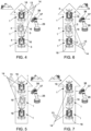
Figures 4 to 7 are schematic plan views showing the correction of the trajectory of the tracked vehicle due to the loss of grip of the track arranged on the opposite side of the anchor point of the winch; and -
Figures 8 to 11 are schematic plan views showing the correction of the trajectory of the tracked vehicle due to the loss of grip of the track arranged on the same side as the anchor point of the cable of the winch. - With reference to
Figure 1 ,reference numeral 1 indicates as a whole a tracked vehicle for preparing ski slopes. The trackedvehicle 1 comprises achassis 2; a track 3 (Figure 2 ); atrack 4; a drive wheel 5 (Figure 2 ) and adrive wheel 6 independent of each other and coupled to the track 3 (Figure 2 ) and to thetrack 4, respectively; a plurality of hydraulically actuatedtools 7 connected to thechassis 2; acab 8 mounted on thechassis 2; and auser interface 9 arranged inside thecab 8 and comprising driving and control instrumentation. - In particular, the
tools 7 comprise atiller 10 movably connected to thechassis 2; ashovel 11 movably connected to thechassis 2; and awinch 12 mounted on thechassis 2 to selectively wind out and wind in acable 13 anchorable to a point 14 (Figure 2 ) external to the trackedvehicle 1. - In accordance with a non-limiting embodiment of the present invention, the
cab 8 is arranged at the front of the trackedvehicle 1 and facing theshovel 11. In such configuration, thewinch 12 comprises adrum 15 pivoting about a pivot axis A1 for winding in and winding out thecable 13 and is arranged at the rear of the trackedvehicle 1, behind thecab 8. - Furthermore, the winch comprises a
boom 16, which is mounted pivoting relative to thechassis 2 about a pivot axis A2, and is configured to guide and orientate thecable 13; an actuation system 17 (Figure 2 ) for actuating theboom 16 about the given axis A2; and acontrol device 18. - The
control device 18 allows implementing the following operating modes also when thecable 13 is under tension: - allowing free rotation of the
boom 16 about the given axis A2; - rotating the
boom 16 about the given axis A2; - locking the position of the
boom 16 relative to thechassis 2. - More specifically, the tracked
vehicle 1 comprises asupport structure 19 fixed to thechassis 2, which sustains thedrum 15 of thewinch 12 and supports theboom 16 in a pivoting manner; and a series ofidler pulleys support structure 19 and on theboom 16 and have the function of guiding thecable 13 along a given path. - With reference to
Figure 2 , theactuation system 17 comprises twoactuators boom 16 for selectively transmitting to theboom 16 respective torques about the pivot axis A2. - In accordance with further embodiments, the number of actuators may vary and should not be understood as limiting the present invention. By way of example, the
actuation system 17 may comprise one single actuator, two actuators, or four actuators. - With reference to
Figure 1 , thecontrol device 18 receives signals from theuser interface 9 in order to control theactuation system 17 and comprises ajoystick 26 controllable by said operator U. - With reference to
Figures 1 and2 , the trackedvehicle 1 has a centre of gravity C, which is arranged at a relatively small distance D1 from the pivot axis A2. - With reference to
Figure 2 , in the described and illustrated case, theactuators support structure 19 and are arranged on opposite sides relative to theboom 16. - In particular, the
actuators - With reference to
Figure 3 , theactuation system 17 comprises ahydraulic circuit 27, which is fed by apump 28. - The
control device 18 comprises apressure modulating valve 29 for adjusting the supply pressure for each actuator 24 and 25 between a minimum and a maximum value; adirection control valve 30; and adirection control valve 31, each of which is configured to selectively shut off power to therespective actuator respective actuator respective actuator - In particular, the actuation system comprises
control modules pressure modulating valve 29, thedirection control valve 30, and thedirection control valve 31, respectively, depending on the commands given by thejoystick 26 and the selected operating mode. - The
control device 18 comprises asensor 35 configured to acquire the direction of travel of the trackedvehicle 1; and acontrol unit 36 to control thecontrol modules user interface 9 and by the signal acquired by thesensor 35. - More specifically, each
control module respective valve actuators - The
joystick 26 comprises twoswitches boom 16 of the winch 12 (Figure 2 ). The twoswitches Figure 1 ). - In accordance with a variation not illustrated, the two buttons are replaced by one single rocker button with an operating position on the left and an operating position on the right and a neutral position in the centre.
- With reference to
Figures 4 and 6 , when theswitch 37 on the right is operated, the trackedvehicle 1 corrects its trajectory by turning to the right. - With reference to
Figures 5 and 7 , when theswitch 38 on the left is operated, the trackedvehicle 1 corrects its trajectory by turning to the left. - With reference to
Figure 4 , the trackedvehicle 1 is moving uphill along a slope by means of the assistance of thewinch 12. Thecable 13 is anchored to theanchor point 14 and theboom 16 is arranged on the right side of the trackedvehicle 1 relative to the direction of travel. - In the illustrated case, the loss of grip of the
left track 4 causes a variation of the trajectory of the trackedvehicle 1. By operatingswitch 37, theboom 16 is rotated anticlockwise so as to induce a compensating torque acting clockwise about the pivot axis A2 for re-establishing the predefined trajectory. - With reference to
Figure 5 , the trackedvehicle 1 is moving uphill along a slope by means of the assistance of thewinch 12. Thecable 13 is anchored to theanchor point 14 and theboom 16 is arranged on the left side of the trackedvehicle 1 relative to the direction of travel. - In the illustrated case, the loss of grip of the
right track 3 causes a variation of the trajectory of the trackedvehicle 1. By operatingswitch 38, theboom 16 is rotated clockwise so as to induce a compensating torque acting anticlockwise about the pivot axis A2 for re-establishing the predefined trajectory. - With reference to
Figure 6 , the trackedvehicle 1 is moving downhill along a slope by means of the assistance of thewinch 12. Thecable 13 is anchored to theanchor point 14 and theboom 16 is arranged on the right side of the trackedvehicle 1 relative to the direction of travel. - In the illustrated case, the loss of grip of the
left track 4 causes a variation of the trajectory of the trackedvehicle 1. By operatingswitch 37, theboom 16 is rotated anticlockwise so as to induce a compensating torque acting clockwise about the pivot axis A2 for re-establishing the predefined trajectory. - With reference to
Figure 7 , the trackedvehicle 1 is moving downhill along a slope by means of the assistance of thewinch 12. Thecable 13 is anchored to theanchor point 14 and theboom 16 is arranged on the left side of the trackedvehicle 1 relative to the direction of travel. - In the illustrated case, the loss of grip of the
left track 4 causes a variation of the trajectory of the trackedvehicle 1. By operatingswitch 38, theboom 16 is rotated clockwise so as to induce a compensating torque acting anticlockwise about the pivot axis A2 for re-establishing the predefined trajectory. - With reference to
Figure 8 , the trackedvehicle 1 is moving uphill along a slope by means of the assistance of thewinch 12. Thecable 13 is anchored to theanchor point 14 and theboom 16 is arranged on the right side of the trackedvehicle 1 relative to the direction of travel. - In the illustrated case, the loss of grip of the
right track 3 causes a variation of the trajectory of the trackedvehicle 1. By operatingswitch 38, theboom 16 is rotated clockwise so as to induce a compensating torque acting anticlockwise about the pivot axis A2 for re-establishing the predefined trajectory. - With reference to
Figure 9 , the trackedvehicle 1 is moving uphill along a slope by means of the assistance of thewinch 12. Thecable 13 is anchored to theanchor point 14 and theboom 16 is arranged on the left side of the trackedvehicle 1 relative to the direction of travel. - In the illustrated case, the loss of grip of the
left track 4 causes a variation of the trajectory of the trackedvehicle 1. By operatingswitch 37, theboom 16 is rotated anticlockwise so as to induce a compensating torque acting clockwise about the pivot axis A2 for re-establishing the predefined trajectory. - With reference to
Figure 10 , the trackedvehicle 1 is moving downhill along a slope by means of the assistance of thewinch 12. Thecable 13 is anchored to theanchor point 14 and theboom 16 is arranged on the right side of the trackedvehicle 1 relative to the direction of travel. - In the illustrated case, the loss of grip of the
right track 3 causes a variation of the trajectory of the trackedvehicle 1. By operatingswitch 38, theboom 16 is rotated clockwise so as to induce a compensating torque acting anticlockwise about the pivot axis A2 for re-establishing the predefined trajectory. - With reference to
Figure 11 , the trackedvehicle 1 is moving downhill along a slope by means of the assistance of thewinch 12. Thecable 13 is anchored to theanchor point 14 and theboom 16 is arranged on the left side of the trackedvehicle 1 relative to the direction of travel. - In the illustrated case, the loss of grip of the
left track 4 causes a variation of the trajectory of the trackedvehicle 1. By operatingswitch 37, theboom 16 is rotated anticlockwise so as to induce a compensating torque acting clockwise about the pivot axis A2 for re-establishing the predefined trajectory. - Since in the described configuration of the tracked
vehicle 1 the distance D1 between the pivot axis A2 and the centre of gravity C is relatively small, the yaw phenomena are negligible and it is not necessary to correct the yaw moment because it is of negligible entity. - With the purpose to allow the free pivoting of the
boom 16 about the given axis A2, in order to arrange theboom 16 aligned with the portion ofcable 13 external to theboom 16, the operator U of the trackedvehicle 1 controls by means of theuser interface 9, actuating the pressure modulating valve 29 (Figure 3 ) so as to apply a minimum torque to theboom 16 by means of each actuator 24, 25 and opposite the minimum torque applied by theother actuator - It is clear that variations can be made to the present invention without thereby departing from the scope of protection of the appended claims.
Claims (10)
- A tracked vehicle for preparing ski slopes, the tracked vehicle (1) comprising:- a chassis (2) extending along a longitudinal axis (A) ;- a winch (12) mounted on the chassis (2);- a boom (16) pivoting about a pivot axis (A2) to guide and orientate the cable (13) of the winch (12) between the chassis (2) and the cable anchor point (14);- an actuation system (17) for rotating the boom (16) about the pivot axis (A2) relative to the chassis (2) in a first and second direction; and- a user interface (9) comprising a first and a second switch (37, 38) arranged in front of an operator (U) and to the right and left of each other and configured to rotate said boom so as to steer the tracked vehicle (1) to the right and to the left respectively when the cable (13) is anchored to the cable anchor point (14).
- The tracked vehicle as claimed in Claim 1, and comprising a control device (18) comprising:- a sensor (35) for detecting the direction of travel of the tracked vehicle (1); and- a control unit (36) configured to enable the first switch (37) to rotate said boom (16) in the first direction in a forward condition and to rotate said boom (16) in the second direction in a reverse condition, and enabling the second switch (38) to rotate said boom (16) in the second direction in a forward condition and in the first direction in a reverse condition.
- The tracked vehicle as claimed in any one of the preceding Claims, wherein the actuation system (17) comprises at least two actuators (24, 25) which are actuatable in a concordant manner to rotate said boom (16) and/or in a discordant manner to lock said boom (16) in a given position.
- The tracked vehicle as claimed in any one of the preceding Claims, wherein the actuation system (17) comprises at least two hydraulic actuators (24, 25); a pump (28) for supplying a fluid under pressure; and a pressure modulating valve (29).
- The tracked vehicle as claimed in Claim 4, wherein the control device (18) comprises for each hydraulic actuator (24, 25) a direction control valve (30; 31) for selectively shutting off power to the respective hydraulic motor or supplying power to the respective hydraulic motor in a first flow direction or supplying power to the respective hydraulic actuator (24, 25) in a second flow direction opposite the first flow direction.
- The tracked vehicle as claimed in Claim 4 or 5, wherein the control device (18) comprises a control module (32) for manually controlling the pressure modulating valve (29) .
- The tracked vehicle as claimed in Claim 5 or 6, wherein the control device (18) comprises further control modules (33, 34) for controlling each direction control valve (30; 31) .
- The tracked vehicle as claimed in any one of the preceding Claims, wherein the user interface (9) comprises a joystick (26); said first and second switches (37, 38) being mounted on said joystick (26).
- A method of driving a tracked vehicle for preparing ski slopes, the method comprising:- connecting the tracked vehicle (1) to an anchor point (14) via the cable (13) of a winch (12);- advancing the tracked vehicle (1);- selectively rotating a boom (16) to guide and orientate the cable (13);- operating a first switch (37) arranged in front of an operator (U) and to the right of a second switch (38); the first switch (37) being configured to rotate said boom (16) so as to turn the tracked vehicle (1) to the right; or- operating a second switch (38) arranged in front of an operator (U) and to the left of the first switch (37), the second switch (38) being configured to rotate said boom (16) so as to turn the tracked vehicle (1) to the left.
- The driving method as claimed in Claim 9, and comprising:- acquiring a signal related to the direction of travel of the tracked vehicle (1);- rotating the boom (16) in a first direction when the first switch (37) is operated and the tracked vehicle (1) is moving forwards or the second switch (38) is operated and the vehicle is moving backwards; and- rotating the boom (16) in a second direction when the first switch (37) is operated and the tracked vehicle (1) is moving backwards or the second switch (38) is operated and the tracked vehicle (1) is moving forwards.
Applications Claiming Priority (1)
| Application Number | Priority Date | Filing Date | Title |
|---|---|---|---|
| IT102022000003908A IT202200003908A1 (en) | 2022-03-02 | 2022-03-02 | TRACKED VEHICLE FOR THE PREPARATION OF SKI SLOPES AND METHOD OF DRIVING THE TRACKED VEHICLE |
Publications (3)
| Publication Number | Publication Date |
|---|---|
| EP4239129A1 true EP4239129A1 (en) | 2023-09-06 |
| EP4239129C0 EP4239129C0 (en) | 2025-04-30 |
| EP4239129B1 EP4239129B1 (en) | 2025-04-30 |
Family
ID=81648247
Family Applications (1)
| Application Number | Title | Priority Date | Filing Date |
|---|---|---|---|
| EP23159344.3A Active EP4239129B1 (en) | 2022-03-02 | 2023-03-01 | Tracked vehicle for preparing ski slopes and method of driving the tracked vehicle |
Country Status (5)
| Country | Link |
|---|---|
| US (1) | US12441399B2 (en) |
| EP (1) | EP4239129B1 (en) |
| CN (1) | CN116691244A (en) |
| CA (1) | CA3193231A1 (en) |
| IT (1) | IT202200003908A1 (en) |
Families Citing this family (1)
| Publication number | Priority date | Publication date | Assignee | Title |
|---|---|---|---|---|
| EP4617094A1 (en) * | 2024-03-12 | 2025-09-17 | PRINOTH S.p.A. | Hydrogen-powered tracked vehicle |
Citations (3)
| Publication number | Priority date | Publication date | Assignee | Title |
|---|---|---|---|---|
| US6585232B2 (en) * | 2000-01-21 | 2003-07-01 | Leitner S.P.A. | Device for setting and automatic adjustment of the tractive force of a cable of an overhead winch for a ski slope preparation and maintenance machine |
| US20100236107A1 (en) * | 2005-06-27 | 2010-09-23 | Helmut Kanzler | Piste Grooming Vehicle With Cable Torque Compensation |
| WO2021100010A1 (en) * | 2019-11-22 | 2021-05-27 | Prinoth S.P.A. | Tracked vehicle comprising a user interface |
Family Cites Families (7)
| Publication number | Priority date | Publication date | Assignee | Title |
|---|---|---|---|---|
| WO2001055511A2 (en) * | 2000-01-28 | 2001-08-02 | Bombardier Inc. | Snow groomer having improved electronic controls |
| DE102007018246A1 (en) * | 2007-04-12 | 2008-10-16 | Kässbohrer Geländefahrzeug AG | vehicle |
| IT1394923B1 (en) * | 2009-02-18 | 2012-07-27 | Rolic Invest Sarl | VEHICLE BATTIPISTA INCLUDING A GROUP WINDOW ASSEMBLY TO MOVE THE VEHICLE LONG DRIVER PENDIUMS SLOPES AND WINDOW GROUP DRIVING METHOD |
| DE102009024644B4 (en) * | 2009-06-03 | 2012-11-15 | Kässbohrer Geländefahrzeug AG | Snowcat with a winch arrangement |
| FR2957326B1 (en) * | 2010-03-12 | 2012-08-03 | Aztec | CABLE TRACTION EQUIPMENT AND VEHICLE |
| DE102010049984A1 (en) * | 2010-10-19 | 2012-04-19 | Kässbohrer Geländefahrzeug AG | Method for controlling a winch of a tracked vehicle and snowcat |
| DE102014008094A1 (en) * | 2014-06-02 | 2015-12-03 | Liebherr-Werk Nenzing Gmbh | Method for controlling the alignment of a crane load and a jib crane |
-
2022
- 2022-03-02 IT IT102022000003908A patent/IT202200003908A1/en unknown
-
2023
- 2023-02-28 US US18/115,267 patent/US12441399B2/en active Active
- 2023-03-01 EP EP23159344.3A patent/EP4239129B1/en active Active
- 2023-03-01 CA CA3193231A patent/CA3193231A1/en active Pending
- 2023-03-02 CN CN202310190281.0A patent/CN116691244A/en active Pending
Patent Citations (3)
| Publication number | Priority date | Publication date | Assignee | Title |
|---|---|---|---|---|
| US6585232B2 (en) * | 2000-01-21 | 2003-07-01 | Leitner S.P.A. | Device for setting and automatic adjustment of the tractive force of a cable of an overhead winch for a ski slope preparation and maintenance machine |
| US20100236107A1 (en) * | 2005-06-27 | 2010-09-23 | Helmut Kanzler | Piste Grooming Vehicle With Cable Torque Compensation |
| WO2021100010A1 (en) * | 2019-11-22 | 2021-05-27 | Prinoth S.P.A. | Tracked vehicle comprising a user interface |
Also Published As
| Publication number | Publication date |
|---|---|
| CA3193231A1 (en) | 2023-09-02 |
| US20230278626A1 (en) | 2023-09-07 |
| US12441399B2 (en) | 2025-10-14 |
| CN116691244A (en) | 2023-09-05 |
| IT202200003908A1 (en) | 2023-09-02 |
| EP4239129C0 (en) | 2025-04-30 |
| EP4239129B1 (en) | 2025-04-30 |
Similar Documents
| Publication | Publication Date | Title |
|---|---|---|
| US6962219B2 (en) | Mechanical ZTR system with steering wheel | |
| KR102120174B1 (en) | Working machine power assist system for use in electric driven platform | |
| US20210114656A1 (en) | Tracked vehicle | |
| CA2626818C (en) | Joystick positioning mechanism | |
| JP2020075697A (en) | Machine steering angle control system | |
| EP4239129A1 (en) | Tracked vehicle for preparing ski slopes and method of driving the tracked vehicle | |
| CA2296249C (en) | Steering responsive power boost | |
| EP1918176B1 (en) | Axle assembly and vehicle | |
| EP4143390B1 (en) | Systems and methods for traction lock engagement control for a power machine | |
| US7237630B2 (en) | Steering arrangement for a work machine | |
| EP4251807B1 (en) | Crawler vehicle for the preparation of ski runs and method to control a winch of the crawler vehicle | |
| JP2005160445A (en) | Farm work machine | |
| JP4796432B2 (en) | Work vehicle travel stop control device | |
| JP2019195284A (en) | Work vehicle | |
| KR200217239Y1 (en) | Steering device installed in armored motorcar on the sea | |
| JP3973063B2 (en) | Rice transplanter | |
| JP3516723B2 (en) | Paddy working machine | |
| JP4797599B2 (en) | Shift control device for toroidal continuously variable tractor | |
| JP2007245861A (en) | Forward / reverse switching control device for work vehicle | |
| WO2025041471A1 (en) | Work vehicle | |
| JP2000326741A (en) | Front wheel speed increase/automatic brake device of tractor | |
| JPH10329747A (en) | Work vehicle | |
| JPH01285628A (en) | Power control method for construction machine | |
| JP2005225462A (en) | Turning device of traveling vehicle | |
| JP2000211389A (en) | Turning device for work vehicle |
Legal Events
| Date | Code | Title | Description |
|---|---|---|---|
| PUAI | Public reference made under article 153(3) epc to a published international application that has entered the european phase |
Free format text: ORIGINAL CODE: 0009012 |
|
| STAA | Information on the status of an ep patent application or granted ep patent |
Free format text: STATUS: THE APPLICATION HAS BEEN PUBLISHED |
|
| AK | Designated contracting states |
Kind code of ref document: A1 Designated state(s): AL AT BE BG CH CY CZ DE DK EE ES FI FR GB GR HR HU IE IS IT LI LT LU LV MC ME MK MT NL NO PL PT RO RS SE SI SK SM TR |
|
| STAA | Information on the status of an ep patent application or granted ep patent |
Free format text: STATUS: REQUEST FOR EXAMINATION WAS MADE |
|
| 17P | Request for examination filed |
Effective date: 20240229 |
|
| RBV | Designated contracting states (corrected) |
Designated state(s): AL AT BE BG CH CY CZ DE DK EE ES FI FR GB GR HR HU IE IS IT LI LT LU LV MC ME MK MT NL NO PL PT RO RS SE SI SK SM TR |
|
| RIC1 | Information provided on ipc code assigned before grant |
Ipc: B66D 1/40 20060101ALI20240919BHEP Ipc: E01H 4/02 20060101AFI20240919BHEP |
|
| GRAP | Despatch of communication of intention to grant a patent |
Free format text: ORIGINAL CODE: EPIDOSNIGR1 |
|
| STAA | Information on the status of an ep patent application or granted ep patent |
Free format text: STATUS: GRANT OF PATENT IS INTENDED |
|
| INTG | Intention to grant announced |
Effective date: 20241114 |
|
| GRAS | Grant fee paid |
Free format text: ORIGINAL CODE: EPIDOSNIGR3 |
|
| GRAA | (expected) grant |
Free format text: ORIGINAL CODE: 0009210 |
|
| STAA | Information on the status of an ep patent application or granted ep patent |
Free format text: STATUS: THE PATENT HAS BEEN GRANTED |
|
| AK | Designated contracting states |
Kind code of ref document: B1 Designated state(s): AL AT BE BG CH CY CZ DE DK EE ES FI FR GB GR HR HU IE IS IT LI LT LU LV MC ME MK MT NL NO PL PT RO RS SE SI SK SM TR |
|
| REG | Reference to a national code |
Ref country code: CH Ref legal event code: EP Ref country code: GB Ref legal event code: FG4D |
|
| REG | Reference to a national code |
Ref country code: IE Ref legal event code: FG4D |
|
| U01 | Request for unitary effect filed |
Effective date: 20250505 |
|
| U07 | Unitary effect registered |
Designated state(s): AT BE BG DE DK EE FI FR IT LT LU LV MT NL PT RO SE SI Effective date: 20250509 |
|
| PG25 | Lapsed in a contracting state [announced via postgrant information from national office to epo] |
Ref country code: ES Free format text: LAPSE BECAUSE OF FAILURE TO SUBMIT A TRANSLATION OF THE DESCRIPTION OR TO PAY THE FEE WITHIN THE PRESCRIBED TIME-LIMIT Effective date: 20250430 |
|
| PG25 | Lapsed in a contracting state [announced via postgrant information from national office to epo] |
Ref country code: GR Free format text: LAPSE BECAUSE OF FAILURE TO SUBMIT A TRANSLATION OF THE DESCRIPTION OR TO PAY THE FEE WITHIN THE PRESCRIBED TIME-LIMIT Effective date: 20250731 |
|
| PG25 | Lapsed in a contracting state [announced via postgrant information from national office to epo] |
Ref country code: PL Free format text: LAPSE BECAUSE OF FAILURE TO SUBMIT A TRANSLATION OF THE DESCRIPTION OR TO PAY THE FEE WITHIN THE PRESCRIBED TIME-LIMIT Effective date: 20250430 |
|
| PG25 | Lapsed in a contracting state [announced via postgrant information from national office to epo] |
Ref country code: HR Free format text: LAPSE BECAUSE OF FAILURE TO SUBMIT A TRANSLATION OF THE DESCRIPTION OR TO PAY THE FEE WITHIN THE PRESCRIBED TIME-LIMIT Effective date: 20250430 |
|
| PG25 | Lapsed in a contracting state [announced via postgrant information from national office to epo] |
Ref country code: RS Free format text: LAPSE BECAUSE OF FAILURE TO SUBMIT A TRANSLATION OF THE DESCRIPTION OR TO PAY THE FEE WITHIN THE PRESCRIBED TIME-LIMIT Effective date: 20250731 |
|
| PG25 | Lapsed in a contracting state [announced via postgrant information from national office to epo] |
Ref country code: IS Free format text: LAPSE BECAUSE OF FAILURE TO SUBMIT A TRANSLATION OF THE DESCRIPTION OR TO PAY THE FEE WITHIN THE PRESCRIBED TIME-LIMIT Effective date: 20250830 |
|
| PG25 | Lapsed in a contracting state [announced via postgrant information from national office to epo] |
Ref country code: SM Free format text: LAPSE BECAUSE OF FAILURE TO SUBMIT A TRANSLATION OF THE DESCRIPTION OR TO PAY THE FEE WITHIN THE PRESCRIBED TIME-LIMIT Effective date: 20250430 |
|
| PG25 | Lapsed in a contracting state [announced via postgrant information from national office to epo] |
Ref country code: CZ Free format text: LAPSE BECAUSE OF FAILURE TO SUBMIT A TRANSLATION OF THE DESCRIPTION OR TO PAY THE FEE WITHIN THE PRESCRIBED TIME-LIMIT Effective date: 20250430 |
|
| PG25 | Lapsed in a contracting state [announced via postgrant information from national office to epo] |
Ref country code: SK Free format text: LAPSE BECAUSE OF FAILURE TO SUBMIT A TRANSLATION OF THE DESCRIPTION OR TO PAY THE FEE WITHIN THE PRESCRIBED TIME-LIMIT Effective date: 20250430 |
|
| PLBE | No opposition filed within time limit |
Free format text: ORIGINAL CODE: 0009261 |
|
| STAA | Information on the status of an ep patent application or granted ep patent |
Free format text: STATUS: NO OPPOSITION FILED WITHIN TIME LIMIT |
|
| REG | Reference to a national code |
Ref country code: CH Ref legal event code: L10 Free format text: ST27 STATUS EVENT CODE: U-0-0-L10-L00 (AS PROVIDED BY THE NATIONAL OFFICE) Effective date: 20260311 |
|
| U20 | Renewal fee for the european patent with unitary effect paid |
Year of fee payment: 4 Effective date: 20260213 |
|
| REG | Reference to a national code |
Ref country code: CH Ref legal event code: U11 Free format text: ST27 STATUS EVENT CODE: U-0-0-U10-U11 (AS PROVIDED BY THE NATIONAL OFFICE) Effective date: 20260401 |
|
| 26N | No opposition filed |
Effective date: 20260202 |
|
| PGFP | Annual fee paid to national office [announced via postgrant information from national office to epo] |
Ref country code: NO Payment date: 20260318 Year of fee payment: 4 |