EP4239117A1 - Lifting rib structure and laundry treatment apparatus - Google Patents
Lifting rib structure and laundry treatment apparatus Download PDFInfo
- Publication number
- EP4239117A1 EP4239117A1 EP21888525.9A EP21888525A EP4239117A1 EP 4239117 A1 EP4239117 A1 EP 4239117A1 EP 21888525 A EP21888525 A EP 21888525A EP 4239117 A1 EP4239117 A1 EP 4239117A1
- Authority
- EP
- European Patent Office
- Prior art keywords
- filtration
- drainage
- cavity
- water flow
- washing drum
- Prior art date
- Legal status (The legal status is an assumption and is not a legal conclusion. Google has not performed a legal analysis and makes no representation as to the accuracy of the status listed.)
- Pending
Links
Images


Classifications
-
- D—TEXTILES; PAPER
- D06—TREATMENT OF TEXTILES OR THE LIKE; LAUNDERING; FLEXIBLE MATERIALS NOT OTHERWISE PROVIDED FOR
- D06F—LAUNDERING, DRYING, IRONING, PRESSING OR FOLDING TEXTILE ARTICLES
- D06F37/00—Details specific to washing machines covered by groups D06F21/00 - D06F25/00
- D06F37/02—Rotary receptacles, e.g. drums
- D06F37/04—Rotary receptacles, e.g. drums adapted for rotation or oscillation about a horizontal or inclined axis
- D06F37/06—Ribs, lifters, or rubbing means forming part of the receptacle
-
- D—TEXTILES; PAPER
- D06—TREATMENT OF TEXTILES OR THE LIKE; LAUNDERING; FLEXIBLE MATERIALS NOT OTHERWISE PROVIDED FOR
- D06F—LAUNDERING, DRYING, IRONING, PRESSING OR FOLDING TEXTILE ARTICLES
- D06F37/00—Details specific to washing machines covered by groups D06F21/00 - D06F25/00
- D06F37/02—Rotary receptacles, e.g. drums
- D06F37/04—Rotary receptacles, e.g. drums adapted for rotation or oscillation about a horizontal or inclined axis
- D06F37/06—Ribs, lifters, or rubbing means forming part of the receptacle
- D06F37/065—Ribs, lifters, or rubbing means forming part of the receptacle ribs or lifters having means for circulating the washing liquid
-
- D—TEXTILES; PAPER
- D06—TREATMENT OF TEXTILES OR THE LIKE; LAUNDERING; FLEXIBLE MATERIALS NOT OTHERWISE PROVIDED FOR
- D06F—LAUNDERING, DRYING, IRONING, PRESSING OR FOLDING TEXTILE ARTICLES
- D06F39/00—Details of washing machines not specific to a single type of machines covered by groups D06F9/00 - D06F27/00
- D06F39/10—Filtering arrangements
Definitions
- the present invention relates to the field of washing machines, in particular to a lifting rib structure and a laundry treatment apparatus.
- a washing drum generally needs to be internally provided with a lifting rib to lift water flow in the washing drum.
- a filtration structure is arranged in the lifting rib to filter impurities such as thread debris in the washing water.
- the filtration structure arranged in the lifting rib generally stores filtered impurities in the lifting rib, and impurities need to be taken out manually when impurities such as thread debris are accumulated to a certain amount.
- a drain opening is arranged on the shell of the lifting rib, and a filter screen is arranged at the drain opening.
- the filtration structure arranged in the existing lifting rib cannot achieve an effect of self-cleaning, and the filtration structure needs to be cleaned or replaced regularly. Therefore, a lifting rib structure is required, and the filtration structure arranged inside the lifting rib can achieve an effect of self-cleaning.
- the object of the present invention is to provide a lifting rib structure.
- the lifting rib structure can filter water flow in the washing drum, and can automatically discharge filtered impurities, thereby achieving an effect of self-cleaning of the filtration structure.
- the present invention further provides a laundry treatment apparatus, in which impurities can be filtered by the lifting rib and the filtration structure can be self-cleaned during drainage.
- a lifting rib structure in the present invention includes a shell, wherein the shell is configured to be fixed on a washing drum inner wall and constitutes an inner cavity together with the washing drum inner wall, the shell is provided with through holes communicated with the interior of the washing drum, a filtration structure is arranged in the inner cavity for filtering water flowing in through the through holes.
- the inner cavity is communicated with a drainage outlet of the washing drum, and a drainage water flow is formed in the inner cavity which flows through the filtration structure from the through holes and flows to the drainage outlet to flush the filtration structure.
- the lifting rib is provided with through holes for allowing water to flow in, and covers at least one drainage outlet, such that the filtration structure inside the lifting rib can filter water inside the washing drum.
- the drainage water flow which flows to the drainage outlet via the through holes and flows through the filtration structure, is generated inside the lifting rib.
- the drainage water flow can flush the filtration structure, to achieve an effect of self-cleaning of the filtration structure, and ensure a filtering effect of the filtration structure.
- a drainage valve is arranged on the drainage outlet for controlling to open and block the drainage outlet.
- the drainage outlet When the drainage outlet is open, the drainage water flow is formed in the inner cavity.
- a flushing water flow is formed in the inner cavity, the flushing water flow flows in and out of the inner cavity through the through holes and flows in a reciprocating manner in the washing drum.
- the filtration structure is arranged at the position, through which the drainage water flow and the flushing water flow flows, in the inner cavity.
- the flushing water flow flows through the filtration structure, such that the flushing water flow can be filtered, to achieve an object of reducing the content of impurities such as thread debris in the water flow in the washing drum.
- the drainage valve controls the drainage holes to be communicated with the inner cavity
- the drainage water flow in the inner cavity flows to the drainage holes through the through holes
- the drainage water flow flows through the filtration structure, such that the drainage water flow can be utilized to flush the filtration structure, and further the filtration structure is self-cleaned.
- the filtration structure includes a filtration surface configured to intercept impurities in the water flow, and an included angle is formed between a water flow direction at the position where the drainage water flow and the flushing water flow flows through the filtration surface and the filtration surface.
- the water flow direction at which the drainage water flow and the flushing water flow flows through the filtration surface is vertical to the filtration surface.
- the included angles are formed between water flow directions, at which the drainage water flow and the flushing water flow flows through the filtration surface, and the filtration surface, such that the drainage water flow and the flushing water flow is in contact with the filtration surface, and further the filtration structure filters the flushing water flow, and the filtration structure is flushed by the drainage water flow. It is achieved an effect of flushing away impurities such as thread debris remained on the filtration surface.
- the lifting rib is extended axially along the washing drum, the through holes are arranged at two sides of the lifting rib, and the filtration structure is arranged closely to the through holes. Both the flushing water flow and the drainage water flow enter into the inner cavity through the through holes, so the filtration structure is arranged closely to the through holes.
- the filtration structure is close to a water source of the flushing water flow, further in contact with more water flow, and filters more water flow.
- the filtration structure is close to the water source of the drainage water flow, such that the filtration structure is flushed by larger water flow, thereby being further convenient for flushing away remaining impurities such as thread debris.
- the filtration structure is arranged at a position corresponding to the side walls provided with through holes of the shell, and is extended towards the washing drum inner wall provided with the drainage outlet.
- the filtration structure is arranged on the side wall which is provided with the through holes, so it is convenient for the filtration structure to be close to the water flow through the through holes, thereby facilitating filtering of the water flow and further facilitating to flush the filtration structure by water flow.
- the lifting rib is internally provided with diversion side walls for guiding the drainage water flow and the flushing water flow.
- a filtration cavity is enclosed by the diversion side walls, the side walls provided with through holes of the shell and the washing drum inner wall.
- the filtration cavity at least covers part of the through holes on the side walls, and the filtration structure is arranged in the filtration cavity.
- the drainage outlet is arranged in the filtration cavity, and the diversion side walls are extended from the side walls to the washing drum inner wall and are abutted against the washing drum inner wall.
- the drainage outlet is arranged outside the filtration cavity.
- Other diversion side walls are extended from the side walls to the washing drum inner wall and are abutted against the washing drum inner wall. According to the arranged position of the drainage outlet, the diversion side walls can be arranged in two ways, and water through the through holes can all flow to the drainage outlet.
- the bottom of the filtration cavity is provided with diversion plates which are extended downwards in an inclined manner from the diversion side walls to the drainage outlet.
- the diversion plates are distributed in the filtration cavity specifically as follows.
- each of the diversion side walls is respectively provided with a diversion plate inclined towards the drainage outlet, a plurality of diversion plates enclose a conical body with a conical tip pointing to the drainage outlet.
- the diversion plates inclined towards the opening are arranged on the diversion side walls far away from the drainage outlet.
- the drainage outlet on the washing drum inner wall is arranged between two diversion side walls, the two diversion side walls are extended from the side walls to the washing drum inner wall and be abutted against the washing drum inner wall.
- the drainage outlet on the washing drum inner wall is arranged outside a space between two diversion side walls. There is a clearance between one diversion side wall close to the drainage outlet of the two diversion side walls and the washing drum inner wall, so the clearance constitutes an opening which allows water in the inner cavity to flow to the drainage outlet.
- Another diversion side wall is extended from the side walls to the washing drum inner wall and be abutted against the washing drum inner wall.
- the side wall, the washing drum inner wall and two diversion side walls enclose a filtration cavity, and the filtration structure is arranged inside the filtration cavity.
- the water flow which has cleaned the filtration structure in the filtration cavity finally needs to be discharged through the drainage outlet. Therefore, the two diversion side walls also need to be arranged to guide cleaning water possibly containing impurities such as thread debris to the drainage outlet. Therefore, according to the arrangement of the position of the drainage outlet and the structures of two diversion side walls, it is ensured that water flow containing impurities such as thread debris can be finally discharged from the drainage outlet.
- the bottom of the filtration cavity is provided with diversion plates which are inclined downwards and toward the drainage outlet from the diversion side walls.
- the two diversion side walls are respectively provided with the diversion plates which are inclined towards the drainage outlet.
- the diversion plate which is inclined towards the opening is arranged on the diversion side wall far away from the drainage outlet.
- the side walls, the washing drum inner wall, two diversion side walls and diversion plates enclose a filtration cavity, and the filtration structure is arranged in the filtration cavity.
- the diversion plate structure is arranged in the filtration cavity, and, the drainage water flow can better flow to the drainage outlet for drainage through the diversion plates.
- the filtration structure includes a filtration surface configured to intercept impurities in the water flow.
- An included angle is formed between the direction of the water flow flowing through the filtration surface in the filtration cavity and the filtration surface.
- the direction of the water flow flowing through the filtration surface in the filtration cavity is vertical to the filtration surface.
- the filtration structure is in a position of in the filtration cavity where the filtration surface configured to intercept impurities such as thread debris is flushed by the drainage water flow. Impurities such as thread debris remained on the filtration surface can be flushed away by water, to ensure cleanness of the filtration structure.
- the filtration surface is arranged to be parallel to the side walls.
- the filtration surface is projected towards the side walls, and the projection covers at least part of the through holes on the side walls.
- the projection covers all the through holes on the side walls.
- the filtration surface is parallel to the side walls, such that inlet water flow in the through holes on the side walls is vertical to the filtration surface.
- the contact area between the inlet water flow at the through holes and the filtration surface is the maximum, thereby facilitating to flush away impurities such as thread debris at the position of the filtration surface by water flow entering from the through holes.
- the filtration surface is arranged at the position close to the side walls in the filtration cavity. Since drainage water flow flows into the filtration cavity from the side walls, water flow at the side walls is the largest.
- the filtration surface is arranged closely to the side walls, such that water flow with a large flow rate flushes the filtration surface, thereby facilitating to flush away impurities such as thread debris at the position of the filtration surface.
- Another object of the present invention is to provide a lifting rib, in which the filtration structure can filter impurities such as thread debris.
- the filtration structure is not easily blocked by impurities such as thread debris, and the filtration structure is also easily cleaned.
- the object of the present invention is further to provide a laundry processing device, and water inside the washing drum can be filtered in the lifting rib, and the lifting rib is not easily blocked during filtering.
- the present invention provides a lifting rib structure.
- the lifting rib structure includes a shell, wherein the shell is provided with through holes for allowing water to flow in and out.
- There is a hollow inner cavity in the shell and comb-shaped filtration structures are arranged in the inner cavity.
- water flow inside the washing drum is filtered by comb-shaped filtration structures.
- the filter screen is a planar structure, while the comb-shaped filtration structures are structures extending in a three-dimensional manner. The contact area of the comb-shaped filtration structures with the water flow is larger, such that the comb-shaped filtration structures achieve a better filtering effect.
- the comb-shaped filtration structures include a plurality of comb teeth, and the comb teeth are of cylindrical structures.
- any arbitrary side wall of the shell is provided with through holes
- the comb teeth are fixed on any arbitrary side wall which is provided with through holes. End parts of the comb teeth are connected with the side walls, and extended towards the washing drum inner wall. When the comb teeth are arranged closely to the through holes, the comb teeth are close to a water inlet source of the through holes.
- the water inlet direction through at least one of through holes is intersected with an extending direction of any arbitrary comb tooth. That is, in the extending direction of the comb teeth, the comb teeth are in contact with water flow flowing from through holes, and further a filtering effect of the comb teeth can be achieved.
- a plurality of comb teeth are distributed as follows.
- a plurality of comb teeth are arranged on the same side wall, a plurality of comb teeth are distributed uniformly on the side walls.
- the comb teeth in each row are arranged horizontally at same interval.
- the comb teeth in each column are arranged longitudinally at same interval.
- a plurality of comb teeth are distributed in multiple rows on the side walls, and the comb teeth in two adjacent rows are distributed in a staggered manner.
- the extending lengths of each row of comb teeth are the same, and the extending lengths of two adjacent rows of comb teeth are different.
- Two comb teeth of adjacent rows are distributed in a staggered manner, so the comb teeth of adjacent rows of do not interrupted by each other. Water flow can be in contact with more comb teeth to be filtered by the comb teeth when water flow flows along any arbitrary direction in the lifting rib.
- the extending lengths of adjacent rows of comb teeth are different, thereby avoiding the bottoms of adjacent comb teeth for interrupted by each other, and similarly enabling the water flow to contact with more comb teeth.
- the comb-shaped filtration structures further include a tree-shaped structure which is extended outwards.
- the tree-shaped structure includes cylindrical rods shaped like trunks, and filtration rods with branch-shaped and protruding outwards are arranged on the cylindrical rods.
- the filtration rods are arranged on the cylindrical rods in an inclined manner, and the filtration rods are gradually extended outwards in an inclined manner from the bottom to the top along axial directions of the cylindrical rods.
- a plurality of filtration rods are arranged at different sides of the cylindrical rods, and the plurality of filtration rods on each side are arranged in sequence on the cylindrical rods along an axial direction.
- the filtration rods being in an inclined manner easily intercept impurities such as thread debris.
- the cylindrical rods are provided with a plurality of filtration rods, such that a plurality of filtration rods all can intercept impurities such as thread debris, thereby achieving a better filtering effect.
- the filtration rods of the comb teeth are arranged the outside, closest to the through holes, of the cylindrical rods, and extended towards the through holes.
- the filtration rods project to the side wall provided with through holes, and the projection can cover part of the area of the through holes.
- the filtration rods of the comb teeth are extended towards through holes closest to the side at which the filtration rods are arranged, such that water flow flowing through the through holes can contact with the filtration rods, and further it is convenient for the filtration rods to intercept impurities such as thread debris in the water flow.
- the filtration rods on the comb teeth are extended towards the through holes, and should also not contact with adjacent comb teeth. If the filtration rods on the comb teeth are abutted against and contact with the adjacent comb teeth, water flow may be easily blocked.
- Another object of the present invention is to further provide a lifting rib structure.
- the lifting rib can achieve an effect of discharging water inside the washing drum, and can also achieve to filter water inside the washing drum. Moreover, the filtering process and the drainage process do not affect each other.
- the object of the present invention is to further provide a laundry processing device, and the laundry processing device can filter and discharge water inside the washing drum by the lifting rib.
- the present invention provides a lifting rib structure.
- the lifting rib structure includes a shell, wherein the shell is configured to be fixed on a washing drum inner wall, the shell constitutes an inner cavity together with the washing drum inner wall.
- the inner cavity includes two independent parts being a filtration space and a drainage space.
- the filtration space exchanges water flow in the washing drum through the through holes arranged on the shell, and the drainage space is used for guiding water inside the washing drum to the drainage outlet formed on the washing drum.
- the drainage space and the filtration space arranged independently in the lifting rib can filter water inside the washing drum and discharge water inside the washing drum, and filtration and drainage of water inside the washing drum are not affected by each other.
- a drainage valve is arranged on the drainage outlet for controlling to open and block the drainage outlet.
- the drainage valve is arranged in the drainage space.
- the drainage space is separated into a drainage cavity and an installation cavity. This drainage cavity is communicated with the drainage outlet and allows to water to be drained.
- the installation cavity is not communicated with the drainage outlet and configured to isolate water flow.
- Part of the structures of the drainage valve is arranged in the installation cavity, and other part of the drainage valve is arranged in the drainage cavity.
- a counterweight structure is arranged on the drainage valve for driving the drainage valve to rise and descend. The counterweight structure and part of the drainage valve are arranged in the installation cavity, and other part of the drainage valve is arranged in the drainage cavity.
- the drainage space is separated by the enclosed installation cavity and the drainage cavity which is communicated with water flow inside the washing drum.
- the counterweight structure is arranged inside the installation cavity, and then the counterweight structure does not contact with water flow in the rising and descending process, thereby preventing water flow from influencing rising and descending of the counterweight structure.
- the drainage valve is arranged along an axial direction of the drainage outlet, and one end of the drainage valve far away from the drainage outlet is connected with the counterweight structure.
- the installation cavity and the drainage cavity are distributed in sequence in an axial direction of the drainage outlet in accordance with a sequence from far to near relative to the drainage outlet. According to the set position of the counterweight structure in the drainage valve, the positions of the installation cavity and the drainage cavity are reasonably distributed.
- the installation cavity is an enclosed cavity connected with the shell.
- the installation cavity includes a plurality of installation cavity side walls extending from the shell to the washing drum inner wall, and an installation cavity bottom wall connected with the bottom ends of all the installation cavity side walls, Installation through holes are arranged at the position, corresponding to the drainage valve, on the installation cavity bottom wall.
- the drainage valve is partially embedded into the installation through holes, and penetrates into the installation cavity from the installation through holes.
- the part of the drainage valve inside the installation cavity is connected with the counterweight structure.
- the installation cavity bottom wall is provided with a limiting groove configured to limit the limit position of the counterweight structure in descending process.
- the counterweight structure descending to the limit position is embedded into the limiting groove.
- the installation cavity bottom wall is provided with a fixing groove configured to fix the drainage valve.
- An inner wall of the fixing groove is consistent with the contour of part of the appearance of the drainage valve, and the drainage valve is partially embedded into the fixing groove.
- the structure of the installation cavity bottom wall is set reasonably, such that a fixing groove can be utilized to fix the drainage valve, and the drainage valve can rise and descend along a set trajectory.
- the lower cavity limit position of the counterweight structure can be limited.
- the drainage cavity is arranged specifically as follows. There is a water inlet clearance between the installation cavity bottom wall and the washing drum inner wall. The water inlet clearance is communicated with the interior of the washing drum. A drainage cavity is constituted between the installation cavity bottom wall and the washing drum inner wall in the drainage space.
- the filtration space is a space communicated with the shell, and the shell corresponding to the filtration space is provided with a plurality of through holes for allowing water flowing in and out.
- the filtration space is internally provided with a filtration structure.
- an opening is arranged on the filtration space for being communicated with the drainage cavity.
- the filtration space is enclosed by the filtration space side walls and the filtration space bottom wall, the filtration space side walls are extended from the shell to the washing drum inner wall.
- the filtration space is an enclosed structure, and the filtration space bottom wall is connected with the bottom ends of all the filtration space side walls.
- the filtration space has the opening, and the filtration space bottom wall is connected with the bottom ends of all the other filtration space side walls except the filtration space side wall closest to the drainage outlet.
- the filtration space can also be provided with the opening being communicated with the drainage cavity, such that sewage after filtering can be discharged from the drainage outlet of the drainage cavity.
- the installation cavity is arranged to be adjacent to the filtration space.
- the installation cavity and the filtration space have a common side wall, the common side wall is extended towards the washing drum inner wall from the shell, and the installation cavity bottom wall is connected with the bottom end the common side wall.
- the installation cavity can be arranged to be adjacent to the filtration space to save space in the inner cavity of the lifting rib.
- the present invention further provides a laundry processing device, containing the above lifting rib structure.
- the present invention has the following beneficial effects as compared with the prior art.
- Reference numerals in the figures 1 . shell; 2. through hole; 3. washing drum inner wall;4. inner cavity; 5. filtration structure; 6. drainage outlet; 7. filtration cavity; 8. side wall; 9. diversion side wall; 10. opening; 11. diversion plate; 12. filtration surface; 13. filter screen; 14. comb-shaped filtration structure;15. drainage valve; 16. lifting rib; 17. comb tooth; 18. inner surface of a side wall; 19. cylindrical rod; 20. filtration rod; 21. filtration space; 22. installation cavity; 23. counterweight structure; 24. installation cavity side wall; 25. installation cavity bottom wall; 26. installation through hole; 27. limiting groove; 28. fixing groove; 29. filtration space side wall; 30. filtration space bottom wall; 31. clearance; 32. common side wall; 33. installation hole; 34. positioning column; 35. drainage space; 36. drainage cavity; 37. water inlet clearance.
- the washing drum inner wall is provided with a lifting rib configured to lift water flow
- a lifting rib configured to lift water flow
- water inside the washing drum is guided into the lifting rib, and a filtration structure is arranged in the lifting rib to filter water inside the washing drum.
- a lifting rib provided with the filtration structure filtered impurities such as thread debris are collected in the lifting rib, and the lifting rib needs to be cleaned regularly to remove impurities. In this way, more impurities such as thread debris possibly remain on the filtration structure arranged inside the lifting rib after long-time use, and then the filtering effect of the filtration structure is influenced. Since the filtration structure in the lifting rib cannot be self-cleaned, the filtration structure needs to be cleaned regularly, which is very troublesome.
- the present invention provides a lifting rib structure 16, the filtration structure 5 inside the lifting rib 16 can be self-cleaned, and the filtration structure 5 can be maintained to be clean without manually cleaning the filtration structure 5, thereby ensuring the filtering effect.
- the lifting rib 16 provided in the present embodiment includes a shell 1 arranged on the washing drum inner wall 3.
- the shell 1 constitutes the contour of an appearance of the lifting rib 16, an inner cavity 4 is constituted by the shell 1 and the washing drum inner wall 3, and the inner cavity 4 is an internal space of the lifting rib 16.
- the shell 1 is provided with through holes 2 for water flowing out and in, such that water inside the washing drum can flow into the inner cavity 4 of the lifting rib 16 through the through holes 2, and water flow inside the inner cavity 4 of the lifting rib 16 can flow out of the inner cavity 4 from the through holes 2.
- a filtration structure 5 is arranged in the inner cavity 4, such that water flowing through the inner cavity 4 of the lifting rib 16 can be filtered by a filtration structure 5.
- a plurality of drainage outlets 6 configured to discharge water inside the washing drum are arranged on the washing drum inner wall 3, and the inner cavity 4 at least covers one drainage outlet 6.
- water flow can flow into the inner cavity 4 of the lifting rib 16 from the through holes 2, and water flowing into the washing drum of the inner cavity 4 is discharged through the drainage outlet 6. That is, drainage water flow in the washing drum includes a drainage path from through holes 2 to a drainage outlet 6, since the inner cavity 4 at least covers one drainage outlet 6, and then the inner cavity 4 at least includes one of the above drainage paths.
- the inner cavity 4 is further provided with a filtration structure 5, such that the drainage path can pass through the filtration structure 5 in the inner cavity 4.
- the filtration structure 5 can be flushed by utilizing drainage water which flows according to a drainage path, thereby achieving an effect of flushing away impurities such as thread debris remained on the filtration structure 5 by utilizing the drainage water flow to clean the filtration structure 5.
- a drainage valve 15 for controlling communication or disconnection between the drainage outlet 6 and the inner cavity 4 is arranged at the drainage outlet 6.
- the inner cavity 4 can be connected with the drainage outlet 6, and the drainage water flow, which flows through the through holes 2 to the drainage outlet 6 and is configured to discharge water out of the washing drum, is formed in the inner cavity 4.
- the filtration structure 5 is arranged at the position through which the drainage water flow flows, the drainage water flow can flush the filtration structure 5 to flush away impurities such as thread debris remained on the filtration structure 5, to achieve an effect of cleaning the filtration structure 5.
- the drainage valve 15 controls the drainage outlet 6 to be disconnected with the inner cavity 4, an impermeable structure except the through holes 2 is formed in the inner cavity 4, and the flushing water flow in the inner cavity 4 flows in and out from the through holes 2 and is in a reciprocating manner between the washing drum and the inner cavity 4.
- the through holes 2 are in different positions. In some positions where the through holes 2 are, water in the washing drum easily flows to the inner cavity 4, and in other positions where the through holes 2 are, water in the inner cavity 4 easily flows inside the washing drum. That is, water flows in a reciprocating manner between the washing drum and the inner cavity 4 to forming the flushing water flow, to achieve an effect of repeatedly flushing the inner cavity 4.
- the filtration structure 5 is arranged at the position, through which the flushing water flow flows, of the inner cavity 4, such that the flushing water flow is filtered by the filtration structure 5 in the flushing process, to achieve an effect of filtering water flow in the washing drum.
- the drainage valve 15 is arranged above the drainage outlet 6, the water flow is controlled to be discharged from the drainage outlet 6 or not by controlling whether the drainage outlet 6 is connected with the inner cavity 4. It is possible that the drainage valve 15 is arranged below the drainage outlet 6, it is directly controlled whether the water flow in the drainage outlet 6 flows outside the washing drum wall.
- the filtration structure 5 is selected from a filter screen 13, comb-shaped filtration structure 14 or the other structures capable of filtration.
- the setting position of the filtration structure 5 in the inner cavity 4 should also be proper, thereby being beneficial for filter treatment of the filtration structure 5 and flushing away impurities such as thread debris remained on the filtration structure 5.
- the filtration structure 5 includes a filtration surface 12 for intercepting impurities in the water flow. After the impurities are filtered by the filtration surface 12 in the filtration process, impurities are adhered onto the filtration surface 12.
- the flushing water flow needs to flow through the filtration surface 12.
- the drainage water flow needs to flow through the filtration surface 12, to flush away impurities such as thread debris remained on the filtration surface 12.
- the filtration surface 12 may be a section of the filter screen 13, or may be a cross section which can intercept impurities such as thread debris in the comb-shaped filtration structures 14.
- each row of comb-shaped bulges all form a plane for intercepting impurities in parallel with the side walls 8 provided with the through holes 2.
- the cross sections in these filtration structures are taken as filtration surfaces 13 to intercept impurities such as thread debris.
- An included angle is formed between the direction of the water flow flowing through the position of the filtration surface 12 in the inner cavity 4 and the filtration surface 12.
- the flushing water flow and the drainage water flow inevitably flow through the filtration surface 12, so the flushing water flow is filtered by the filtration surface 12, and the drainage water flow can flush away impurities such as thread debris remained on the surface of the filtration surface 12.
- the direction of the water flow flowing through the position of the filtration surface 12 in the inner cavity 4 is vertical to the filtration surface 12.
- the flushing water flow and the drainage water flow are vertical to the filtration surface 12, in this way, the contact area the filtration surface 12 with the drainage water flow or the flushing water flow is the maximum.
- the filtration surface 12 is set to be parallel to the side walls 8 provided with through holes 2 on the shell 1. Since the side walls 8 are provided with through holes 2 for water flowing in, the filtration surface 12 is set to be parallel to the side walls 8, such that water flow through the through holes 2 on the side walls 8 is vertical to the filtration surface 12. Moreover, both the flushing water flow and the drainage water flow enter into the inner cavity 4 through the through holes 2, and the filtration surface 12 is arranged in parallel to the side walls 8 with through holes 2, such that drainage water flow entering into the inner cavity 4 easily flushes the filtration surface 12, and the flushing water flow entering into the inner cavity 4 can be filtered.
- the filtration surface 12 projects towards the side walls 8, and the projection at least covers part of the through holes 2 on the side walls 8.
- the projection covers all the through holes 2 on the side walls 8. In this way, water flow entering through the through holes 2 on the side walls 8 flows to the filtration surface 12.
- the filter screen 13 needs to be arranged to be parallel to the side walls 8, such that drainage water flow flowing via the through holes 2 on the side walls 8 can directly flow to the filter screen 13, thereby achieving an effect that the flushing water flow is filtered by the filter screen 13 and the drainage water flow flushes the filter screen 13.
- the filtration surface 12 is arranged at the position close to the side walls 8 in the filtration cavity 7. Since the through holes 2 for water flowing in are arranged on the side walls 8, the filtration surface 12 is set to be close to the side walls 8, and then the filtration surface 12 is close to the through holes 2 for water flowing in.
- the water flow entering into the inner cavity 4 must be larger when the water flow is closer to the water inlet. Therefore, when the filtration surface 12 is set to be close to the through holes 2 for water flowing in, and the filtration surface 12 can be flushed with larger water flow, thereby being further beneficial for removing impurities such as thread debris remained on the filtration structure 5.
- the water flow at the position of the through holes 2 is the largest.
- the filtration surface 12 When the filtration surface 12 is arranged close to the side walls 8 provided with through holes 2, the filtration surface 12 can filter more water flow entering into the inner cavity 4, to further achieve a better filtering effect.
- the lifting rib 16 is extended axially along the washing drum, through holes 2 are arranged at two sides of the lifting rib, and the filtration structure 5 is arranged to be close to the through holes 2.
- the lifting rib 16 is internally provided with a diversion side wall 9 which guide the drainage water flow and the cleaning water flow to flow.
- the diversion side walls 9, the side walls 8with through holes 2 of the shell 1 and the washing drum inner wall 3 enclose a filtration cavity 7, the filtration cavity 7 at least covers part of the through holes 2 on the side walls 8, and the filtration structure 5 is arranged in the filtration cavity 7. That is, the filtration cavity 7 is used for connecting the through holes 2 of the shell 1 with the drainage outlet 6 on the washing drum inner wall 3, to discharge water out of the washing drum.
- the filtration structure 5 is arranged in the filtration cavity 7, such that the filtration structure 5 in the filtration cavity 7 is cleaned when water inside the washing machine inner drum flows along the filtration cavity 7,.
- the position and structure of the lifting rib 16 on the washing drum inner wall 3 of the present embodiment are set reasonably, such that the inner cavity 4 of the lifting rib 16 can constitute a filtration cavity 7 which guides the drainage water flow and flushing water flow.
- the flushing water flow can be guided to flow through the filtration structure 5 by the filtration cavity 7 and can be filtered by the filtration structure 5, and the drainage water flow can be guided to flow through the filtration structure 5 by the filtration cavity 7. In this way, the filtration structure 5 can be cleaned automatically by utilizing the drainage water flow in the washing drum.
- the drainage water flow in the filtration cavity 7 is as water supplied to clean the filtration structure 5, so it should be ensured to have sufficient water flow of the filtration cavity 7 during drainage. Therefore, partition plates can be arranged in the inner cavity 4 of the lifting rib 16, and the partition plates can enclose a filtration cavity 7.
- the filtration cavity 7 enclosed by the partition plates can is arranged to guide the drainage water to flow according to a set trajectory, and further the water flow is controlled to better flow through the filtration structure 5.
- the shell 1 of the lifting rib 16 includes a plurality of side walls 8, the side walls 8 are provided with a plurality of through holes 2.
- the side walls 8 are connected with two diversion side walls 9 which enclose the filtration cavity 7, and the diversion side walls 9 can be arranged to be vertical to the side walls 8 and extend from the side walls 8 towards the washing drum inner wall 3.
- the area between diversion side walls 9 on the side walls 8 at least covers part of the through holes 2 on the side walls 8, and the filtration structure 5 is arranged between two diversion side walls 9.
- the area between the diversion side walls 9 covers all of the through holes 2 on the side walls 8.
- the diversion side walls 9 are guiding structures being a partition plate.
- the above specific structure of the filtration cavity 7 enclosed by the diversion side walls 9 includes two types.
- One type is that the drainage outlet 6 on the washing drum inner wall 3 is between diversion side walls 9, and the other type is that the drainage outlet 6 on the washing drum inner wall 3 is arranged outside the space between the diversion side walls 9.
- the diversion side walls 9 extend from the side walls 8 to the washing drum inner wall 3 and is abutted against the washing drum inner wall 3, that is, the diversion side walls 9 all are connected with the side walls 8 and the washing drum inner wall 3.
- the diversion side walls 9, the side walls 8 and the washing drum inner wall 3 enclose the filtration cavity 7 which is only provided with through holes 2 and a drainage outlet 6 and the remaining positions being impermeable.
- the filtration structure 5 is arranged inside the filtration cavity 7, such that the water flow can be guided to form the drainage water flow and the flushing water flow, and the drainage water flow can flow through the filtration structure 5 to clean the filtration structure 5, and the flushing water flow flows through the filtration structure 5 to be filtered.
- an opening 10 at least needs to be arranged in the filtration cavity 7, such that the drainage water flow can flow into the drainage outlet 6 from the opening 10.
- the clearance constitutes an opening 10 for allowing the water flow in the inner cavity 4 to flow to the drainage outlet 6.
- the other diversion side walls extend from the side walls 8 to the washing drum inner wall 3 and are abutted against the washing drum inner wall 3. That is, the diversion side wall close to the drainage outlet 6 of the diversion side walls extends from the side walls 8 towards the washing drum inner wall 3, but, the end of the diversion side wall does not extend to and be abutted against the washing drum inner wall 3, so there is a clearance between the diversion side wall and the washing drum inner wall 3 to form the opening 10.
- the drainage water flow flows through the opening 10, and finally flows to the drainage outlet 6 for drainage.
- the diversion side walls 9 can also all be arranged to extend from the side walls 8 to the washing drum inner wall 3 and be abutted against the washing drum inner wall 3, and the opening 10 is formed on one diversion side wall close to the drainage outlet 6.
- the side walls 8, the washing drum inner wall 3 and the diversion side walls 9 enclose a filtration cavity 7 with the opening 10, and the filtration structure is arranged in the filtration cavity 7. Through the arrangement of the filtration cavity 7, water flow can be better guided to form a drainage path, and the drainage path flows through the filtration structure 5 to clean the filtration structure 5.
- a diversion plate 11 for guiding the water flow to the drainage outlet 6 can be arranged inside the filtration cavity 7.
- the diversion plates 11 Through the arrangement of the diversion plates 11, the water flow inside the filtration cavity 7 easily gathers at the drainage outlet 6, such that the water flow flowing to the drainage outlet 6 is large.
- the water flow which contains impurities such as thread debris can be guided to flow to the drainage outlet 6 by the diversion plates 11 for drainage.
- the water flow contains impurities such as thread debris which block flow of the water flow after the filtration structure 5 is cleaned, so the diversion plates 11 are set to enable the water flow to be more gathered, and the water flow flowing to the drainage outlet 6 is larger. So thread debris is easily discharged out from the drainage outlet 6.
- the bottom of the filtration cavity 7 is provided with the diversion plate 11 which is inclined downwards from the diversion side walls 9 to the drainage outlet 6, and the inclined structure of the diversion plate 11 is more beneficial for the drainage water flow to flow to the drainage outlet 6 along the diversion plate 11.
- the inclined structures of the diversion plate 11 enables to improve the flow rate of the drainage water flow, so it is more beneficial for flushing away impurities such as thread debris in the drainage water flow.
- the drainage outlet 6 can be set in two positions, which can be arranged between the diversion side walls 9 or arranged outside the space between the diversion side walls 9.
- the diversion plate 11 for guiding water flow to flow to the drainage outlet 6 also has two structures.
- each of the diversion plates 11 constitute a conical surface with a conical tip pointing to the drainage outlet 6.
- a conical surface of the inclined diversion plates 11 makes the area of the section flowing towards the drainage outlet 6 be gradually reduced, such that the flow velocity of the water flow which flows to the drainage outlet 6 is accelerated, and it is more beneficial for discharging the water flow carrying thread debris through the drainage outlet 6.
- the opening 10 should be arranged on one diversion side wall close to the drainage outlet 6, the drainage water flow in the filtration cavity 7 is guided to flow towards one side with the opening 10. The drainage water flow needs to flow towards one diversion side wall which is provided with the opening 10.
- the diversion plate 11 inclined towards the opening 10 is arranged on the part above the opening 10 on one diversion side wall far away from the drainage outlet 6, and the diversion plate 11 guides the drainage water flow to flow to the drainage outlet 6 for drainage.
- the side walls 8, the washing drum inner wall 3, two diversion side walls 9 and the diversion plates 11 together enclose the filtration cavity 7, and the filtration structure is arranged inside the filtration cavity 7.
- the structure inside the lifting rib 16 is reasonably set, such that the flushing water flow entering into the lifting rib 16 can be filtered by the filtration structure 5, and the drainage water flow cleans the filtration structure 5 inside the lifting rib 16 to flush impurities such as thread debris remained on the filtration structure 5, and ensure a filtering effect of the filtration structure 5.
- the filtration structure 5 inside the lifting rib 16 provided in the present invention can be self-cleaned. The filtration structure 5 is no need to be cleaned manually, and the filtration structure 5 can be self-cleaned by the drainage water inside the washing drum.
- the present embodiment provides a holeless washing machine on the basis of the above embodiment.
- the holeless washing machine is generally provided with a washing drum. Washing water can be introduced to be utilized for washing, and the washing water is discharged for drying so the functions of washing and drying is operated by one washing drum.
- a drainage outlet 6 is arranged on the washing drum inner wall 3
- a drainage valve 15 is arranged on the drainage outlet 6, and the water flow at the drainage outlet 6 can be controlled to be discharged or not be discharged by the drainage valve 15.
- the drainage outlet 6 is kept to be isolated from the washing drum in the process of water inlet and washing, the washing drum is enclosed, and water flow does not flow out of the washing drum.
- the flushing water flow is formed, and the filtration structure 5 filters the flushing water flow.
- the drainage valve 15 can be utilized to control the drainage outlet 6 to be communicated with the washing drum, such that in the drainage and drying process, water flow in the washing drum is discharged through the drainage outlet 6.
- the drainage water flow which can flush the filtration structure 5 is just formed to clean the filtration structure 5. That is, the holeless washing machine can utilize the discharged water to realize self-cleaning of the filtration structure 5 in the lifting rib 16, to ensure a filtering effect.
- a washing machine is provided with a washing drum configured to accommodate washing water, wash laundry and discharge washing water, and the washing drum inner wall 3 is generally provided with a lifting rib for lifting water flow.
- the lifting rib includes a shell 1 arranged on the washing drum inner wall 3, and an inner cavity 4 is constituted by the shell 1 and the washing drum inner wall 3.
- the contour of appearance of the shell 1 of the lifting rib actually is utilized to lift water flow, while the inner cavity 4 is an empty cavity. To save space, the component required inside the washing machine is arranged in the empty cavity of the inner cavity 4.
- a filtration structure is arranged in the space of the inner cavity 4, through holes 2 for water flowing in and out are arranged on any arbitrary side wall 8 on the shell 1, such that water in the washing drum can flow into the inner cavity 4 through the through holes 2, and is filtered by the filtration structure in the inner cavity 4, and the filtered water can flow into the inner cavity 4 again through the through holes 2, to achieve an effect of filtering water.
- the filter screen is generally arranged in the lifting rib, but the filter screen has the shortcomings of easy remaining of impurities such as thread debris, difficulty in cleaning, and requirement of regular replacement. Therefore, the present embodiment provides a lifting rib as shown in the figure, and a comb-shaped filtration structure 14 is arranged in the lifting rib.
- the comb-shaped filtration structure 14 is not easily blocked by impurities such as thread debris, and is easy to be cleaned.
- the comb-shaped filtration structure 14 is extending in a comb-teeth shape.
- the comb-shaped filtration structure 14 Compared with a previous planar filter screen, the comb-shaped filtration structure 14 obviously has a large volume extending direction and can be in contact with more water flow, and more water flow entering into the lifting rib is filtered to achieve better filtering effect. Moreover, the clearance of the comb-shaped filtration structure 14 is greater than meshes on the filter screen, and the extending volume of the comb-shaped filtration structure 14 is large, such that thread debris does not easily lead to blockage of the comb-shaped filtration structure 14 and can be easily flushed out.
- the comb-shaped filtration structure 14 includes a plurality of comb teeth 17.
- impurities such as thread debris can hang on the comb teeth 17, to further achieve an effect of filtering impurities.
- the comb teeth of the comb-shaped filtration structure 14 can be of various different shapes, as long as the shape is convenient for intercepting impurities such as thread debris.
- the comb teeth 17 are set to be cylindrical rod structures, such that the comb teeth 17 are easily processed.
- the contact area of water flow in the lifting rib with the comb teeth 17 should be as large as possible.
- Water flow flows to the lifting rib through the through holes 2 arranged on any arbitrary side wall 8.
- Water flow is obviously most concentrated at the position where water flow flows to the lifting rib and the water flow is the largest. Water flow may be divergent and flows along any arbitrary direction in the lifting rib, after entering into the lifting rib.
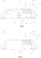
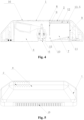
- the comb teeth 17 can be fixed on the side wall 8 provided with through holes 2. Specifically as shown in Fig. 3 and Fig.
- the comb teeth 17 are arranged on any side wall 8 provided with through holes 2, and the top parts of the comb teeth 17 are connected with inner surface of the side wall 8, and extend towards the washing drum inner wall 3.
- the comb teeth 17 are fixed on the side wall 8 provided with through holes 2, such that the comb teeth 17 are close to the through holes 2 for water flowing in, and are more concentrated after flowing into the lifting rib. Larger water flow can be directly contact with the comb teeth 17, and be filtered by the comb teeth 17.
- Water flow entering into the lifting rib through the through holes 2 can flow along any arbitrary direction.
- the comb teeth 17 is extended towards the washing drum inner wall 3 along the fixed side wall 8. That is, the comb teeth 17 have a certain extending distance between the shell 1 and the washing drum inner wall 3.
- Water flow which flows inside the lifting rib and is capable of flowing to the lifting rib from the through holes 2 and flowing back to the washing drum through the through hole 2 may possibly contact with the comb teeth 17, and is filtered by the comb teeth 17.
- through holes 2 are arranged on a plurality of the side walls 8 on the shell 1.
- the comb teeth 17 are correspondingly arranged on a plurality of side walls 8.
- the lifting rib generally extends along an axial direction of the washing drum inner wall 3. When water flow in the washing drum flows to the lifting rib, and water flow easily flows through the through holes 2 arranged on a circumferential side wall of the shell 1, therefore, comb teeth 17 can be fixed on the inner surface 18 of the circumferential side wall.
- a plurality of comb teeth 17 can be arranged on the same side wall. When more comb teeth 17 are available, the comb teeth 17 need to be distributed so as to not be affected among the comb teeth 17.
- a plurality of comb teeth 17 arranged on the same side wall 8 are distributed.
- the comb teeth 17 in each row are arranged at the same intervals horizontally; and/or when the plurality of comb teeth 17 are distributed in columns, the comb teeth 17 in each column are arranged at the same intervals longitudinally.
- Uniform distribution of the comb teeth 17 is convenient for processing and controlling the spacing between adjacent comb teeth 17.
- the spacing between adjacent comb teeth 17 is set to a set value, and a user can set the set value according to ordinary size of impurities such as thread debris.
- the set value is usually small, and the spacing between adjacent comb teeth 17 is small, such that impurities such as thread debris easily hang on the comb teeth 17 or are blocked between two comb teeth 17.
- a plurality of comb teeth 17 are distributed in rows; and/or when through holes 2 on the same side wall 8 are distributed in columns, a plurality of comb teeth 17 are distributed in columns. Since the comb teeth 17 need to be flushed with water flow flowing through the through holes 2, the distribution of comb teeth 17 should be consistent with the distribution of through holes 2. Therefore, when the through holes 2 are distributed in rows, the comb teeth 17 are also distributed in rows. When the through holes 2 are distributed in columns, the comb teeth 17 are also distributed in columns.
- a plurality of comb teeth 17 arranged on the same side wall 8 are distributed in multiple rows on the side walls 8, and the comb teeth 17 between two adjacent rows are distributed in a staggered manner. That is, after the position of one row of comb teeth 17 is fixed, the comb teeth 17 of adj acent rows are all arranged in a clearance between the comb teeth 17 in the one row. Through such a setting, the comb teeth 17 in adjacent rows are not be blocked, thereby avoiding influencing the filtering effect of the comb teeth 17.
- the extending lengths of the comb teeth 17 in each row are the same, and the extending lengths of the comb teeth 17 in two adjacent rows are different.
- the extending lengths of the comb teeth 17 in two adjacent rows are different, such that the comb teeth 17 are also distributed in a staggered manner along a length direction.
- Water flow entering into the inner cavity 4 can flow in the inner cavity 4 in all directions.
- a plurality of rows of comb teeth 17 are distributed in a staggered manner along the direction of multiple rows, and the multiple rows of comb teeth 17 are distributed in a staggered manner along a length direction.
- the Comb-shaped filtration structure 14 is arranged in the lifting rib provided in the present embodiment for filtering water flow in the washing drum.
- the comb-shaped filtration structure 14 of the present embodiment has more clearances, such that impurities such as debris do not easily block the filtration structure.
- the comb-shaped filtration structure 14 in the present embodiment extends for a certain length, such that the comb-shaped filtration structure 14 can achieve a better filtering effect compared with a thin filter screen.
- the present embodiment provides a lifting rib on the basis of the above embodiments.
- the lifting rib is also provided with comb-shaped filtration structures 14, and the difference lies in that the structure of the comb teeth 17 of the comb-shaped filtration structures 14 of the present embodiment is different from the structure of the comb teeth 17 in Embodiment 1.
- the comb teeth 17 in the present embodiment are similar to tree-shaped structures. As shown in Fig. 6 , the comb teeth 17 include cylindrical rods 19 and filtration rods 20 arranged on the cylindrical rods 19, and the filtration rods 20 are protruded outwards and are branch-shaped. As Embodiment 1, the cylindrical rods 19 themselves can be used for hanging impurities such as thread debris, and impurities such as thread debris may be blocked between adjacent cylindrical rods 19.
- the filtration rods 20 with branch-shaped arranged on the cylindrical rods 19 can also be used for hanging impurities such as thread debris on the filtration rods 20, and impurities such as thread debris can be blocked between the cylindrical rods 19 and the filtration rods 20.
- the filtration rods 20 are arranged on the cylindrical rods 19 in an inclined manner.
- Each filtration rod 20 is gradually extended outwards in an inclined manner from the bottom to the top along an axial direction of the cylindrical rods 19.
- the impurities such as thread debris more easily hang on the filtration rods 20 which are arranged in an inclined manner, and impurities such as thread debris are easily blocked between the filtration rods 20 and the cylindrical rods 19.
- the ends of the comb teeth 17 are fixedly connected with the side wall of the shell 1.
- the other ends of the comb teeth 17 are closer to the washing drum inner wall 3, and water flow in the lifting rib generally needs to flow the washing drum inner wall 3 through the shell 1. Therefore, through the arrangement of the filtration rods 20 gradually extending outwards in an inclined manner from the bottom to the top, impurities such as thread debris in the water flow are easily intercepted by the filtration rods 20 along the movement of the water flow, to achieve a better filtering effect. That is, the filtration rods 20 are gradually closer to the cylindrical rods 19 along a direction of the water flow, such that impurities such as thread debris can be easily blocked into or hang on the filtration rods 20. As shown in Fig.
- a plurality of filtration rods 20 are arranged at different sides of the cylindrical rods 19, and a plurality of filtration rods 20 on each side are arranged in sequence on the cylindrical rods 19 along an axial direction.
- the filtration rods 20 arranged at different sides of the cylindrical rods 19 enlarge an unfolded area of the cylindrical rods 19, thus it is further easy to intercept impurities such as thread debris.
- the filtration rods 20 can be distributed to save space, thereby the volume of the comb teeth 17 is reduced, and adjacent comb teeth 17 do not easily affect each other.
- the cylindrical rods 19 are fixed on the side wall 8 which is provided with through holes 2, so the cylindrical rods 19 can only be arranged in a staggered manner with the through holes 2. In fact, water flow flows through the through holes 2. Therefore, in order to filter water flow, the filtration rods 20 should be extended towards the position of the through holes 2, and water flow flowing through the through holes 2 can be directly in contact with the filtration rods 20 to be filtered through the filtration rods 20.
- the cylindrical rods 19 cannot be directly arranged on the through holes 2 of the side walls 8, but the filtration rods 20 on the cylindrical rods 19 are extended outwards from the cylindrical rods 19 and just face to the through holes 2, so that the contact area between the water flow and the filtration rods 20 is increased to further improve the filtering effect of the filtration rods 20.
- the filtration rods 20 are arranged on the outside of the cylindrical rods 19 closest to the through holes and extended towards the through holes 2, and the filtration rods 20 project onto the side walls 8 provided with through holes 2, and the projection can cover part of the area of the through holes 2.
- the filtration rods 20 correspond to part of the area of the through holes 2, and water flow flowing through the through holes 2 is in contact with the filtration rods 20 to be filtered by the filtration rods 20.
- the filtration rods 20 on each side of the cylindrical rods 10 extend towards the through holes 2 closest to the corresponding side.
- the filtration rods 20 arranged on the right side of the cylindrical rods 19 in the figures are all extended towards the closest through holes 2 on the right sides of the filtration rods 20, and the filtration rods 20 on left sides of the cylindrical rods 19 are all extended towards the closest through holes 2 on the left sides of the filtration rods 20. That is, a plurality of filtration rods 20 on the cylindrical rods 19 respectively are extended outwards along their respective sides, such that the filtration rods 20 are fully unfolded on the cylindrical rods. Water flow is fully in contact with the filtration rods 20 to achieve a better filtering effect.
- the filtration rods 20 on different sides of the cylindrical rods 17 all extend outwards, the filtration rods 20 cannot contact with adjacent cylindrical rods 17. Specifically, there is a clearance between all the filtration rods 20 arranged on any cylindrical rods 17 and adjacent cylindrical rods 17. If there is no clearance between the filtration rods 20 and adjacent cylindrical rods 17, an abutted position exists, and water flow cannot flow through the abutted position. At this time, if impurities such as thread debris are still on the filtration rods 20, water flow is easier to be blocked completely. Therefore, the clearance is kept between the filtration rods 20 and their adjacent cylindrical rods 17. As the comb-shaped filtration structure 14 in the lifting rib provided in the present embodiment, the structural of the comb teeth 17 is more reasonable.
- the filtration rods 20 are further arranged on the cylindrical rods 19, so impurities such as thread debris may hang on or be blocked onto the filtration rods 20 to further achieve a better filtering effect for the comb-shaped filtration structures 14. Moreover, the filtration rods 20 are arranged to enlarge an overall unfolded area of the comb teeth 17 and further increase the contact area between the comb teeth 17 and water flow, such that more water flow is filtered by the comb teeth 17 to improve the filtering effect.
- the washing drum inner wall 3 is generally provided with a lifting rib 16 for lifting water flow.
- the lifting rib 16 includes a shell 1 arranged on the washing drum inner wall 3, and an inner cavity 4 constituted between the shell 1 and the washing drum inner wall 3.
- the inner cavity 4 has a certain space.
- parts required in the washing machine can be arranged in the inner cavity 4 of the lifting rib 16.
- a drainage device is arranged in the inner cavity 4 of the lifting rib 16 in some patents.
- the washing drum inner wall 3 is generally provided with a drainage outlet 6, each of the lifting ribs 16 at least covers one drainage outlet 6, and a drainage valve 15 for blocking the drainage outlet 6 is correspondingly arranged at the position of the drainage outlet 6 in the inner cavity 4 of the lifting rib 16, to achieve an effect of controlling to open and close the drainage outlet 6 by the drainage valve 15.
- the washing machine only having one washing drum can operate to feed water and wash laundry by controlling the drainage outlet 6 to be closed, and to drain water by controlling the drainage outlet 6 to be open. That is, in one washing drum, a complete washing processes of feeding water, washing, drying and dehydration in a washing drum can be realized.
- a lifting rib structure is provided at present.
- the structure inside the lifting rib is reasonably designed to make a plurality of parts required inside a washing machine be arranged simultaneously inside the lifting rib, and multiple parts are not affect each other.
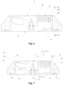
- the present invention provides the lifting rib 16 as shown in the figure.
- the inner cavity 4 of the lifting rib 16 of the present invention includes two independent spaces: a filtration space 21 and a drainage space 35.
- the filtration space 21 is configured to filter water flow inside a washing drum, and the drainage space 35 is configured to discharge water inside the washing drum.
- the shell 1 is provided with through holes 2 through which water flow in the shell is exchanged with the water flow inside the washing drum.
- the filtration space 21 covers the through holes 2 arranged on the shell 1.
- the filtration space 21 can exchange water flow with the washing drum.
- the filtration space 21 filters the water flow flowing into the filtration space 21 from the washing drum, and the water flow being filtered is discharged to the washing drum 5.
- the drainage outlet 6 is arranged on the washing drum inner wall 3 for draining the water out of the washing drum.
- the drainage space 35 at least covers one drainage outlet 6, and the drainage space 35 can guide water inside the washing drum to flow the drainage outlet 6 formed on the washing drum inner wall 3, to achieve an effect of drainage.
- the drainage outlet 6 is provided with a drainage valve 15 for controlling to communicate and block the water flow at the drainage outlet 6.
- the drainage valve 15 includes a valve element which can rise and descend, and the valve element can correspondingly block the drainage outlet 6.
- the valve element when the valve element descends to block the drainage outlet 6, water flow cannot be discharged from the drainage outlet 6.
- the rising and descending of the valve element is realized by the counterweight structure 23 connected with the valve element to drive rising and descending of the valve element.
- the counterweight structure 23 with larger gravity can rise and descend, and the valve element connected with the counterweight structure 23 can be driven to rise and descend by the rising and descending of the counterweight structure 23.
- the drainage space 35 is further separated into two independent cavities, that is, an installation cavity 22 and a drainage cavity 36.
- the installation cavity 22 is an enclosed cavity into which water flow cannot flow, and the counterweight structure 23 and part of the drainage valve 15 are arranged in the installation cavity 22, so the rising and descending movement of the counterweight structure 23 cannot be affected by water flow.
- impurities such as thread debris may be wound on the counterweight structure 23, therefore normal rising and descending of the counterweight structure 23 may be influenced, the valve element cannot reach the set position accurately and accurately control to communicate and block the water flow at the drainage outlet 6. So the installation cavity 22 for installing the counterweight structure 23 should be an enclosed cavity into which no water flow can enter.
- the drainage space 35 further includes a drainage cavity 36 for discharging water flow.
- the other structures of the drainage valve 15 not arranged in the installation cavity 22 and the drainage outlet 6 are all arranged in the drainage cavity 36. Since the drainage cavity 36 plays a role of drainage, the drainage cavity 36 may allow water inside the washing drum to flow in and drain out through the drainage outlet 6, therefore, the drainage cavity 36 is set to be a cavity which is not enclosed.
- the drainage valve 15 is driven by the other structures.
- the drainage valve 15 is an electromagnetic valve
- parts such as electromagnetic parts which may be affected by water flow can be arranged in the installation cavity 22, and the other parts of the drainage valve 15 are arranged in the drainage cavity 36.
- the drainage valve 15 is arranged along an axial direction of the drainage outlet 6, and one end of the drainage valve 15 away from the drainage outlet 6 is connected to the counterweight structure 23.
- the valve element can be driven to descend to block the drainage outlet 6, and the drainage outlet 6 is sealed.
- the valve element is driven to rise and water flow is further discharged from the drainage outlet 6.
- the installation cavity 22 and the drainage cavity 36 are distributed in sequence along an axial direction of the drainage outlet 6 and in a direction from far to near relative to the drainage outlet 6.
- the counterweight structure 23 is arranged on an end, far away from the drainage outlet 6, of the drainage valve 15, therefore, so the installation cavity 22 for accommodating the drainage valve 15 should be arranged at the position far away from the drainage outlet 6 along an axial direction of the drainage outlet 6. That is, as shown in the figure, the installation cavity 22 and the drainage cavity 7 can be distributed in up and down direction.
- the installation cavity 22 should be an enclosed cavity. It has been discussed above that the installation cavity 22 should be arranged on a side, far away from the drainage outlet 6, in the drainage space 35.
- the drainage outlet 6 is arranged on the washing drum inner wall 3, and the shell 1 is far away from the washing drum inner wall 3, therefore, the installation cavity 22 is formed by the shell 1.
- the installation cavity 22 is an enclosed cavity which is connected with the shell 1.
- the installation cavity 22 includes the installation cavity side walls 24 extending from the shell 1 to the washing drum inner wall 3, and an installation cavity bottom wall 25 connected with lower end faces of all the installation cavity side walls 24.
- An installation through hole 26 is arranged at the position corresponding to the drainage valve 15 on the installation cavity bottom wall 25, the drainage valve 15 is partially embedded into the installation through hole 26, and penetrates into the installation cavity 22 via the installation through hole 26.
- the drainage valve 15 partially penetrates into the installation cavity 22 and is connected with the counterweight structure 23.
- a sealed structure can be arranged at the position of the installation through hole 26, thereby preventing leakage at the installation through hole 26.
- the installation cavity bottom wall 25 is provided with a limiting groove 27 which limits a limit position at which the counterweight structure 23 descends at the largest extent.
- the counterweight structure 23 descends to the limit position to be embedded into the limiting groove 27.
- the counterweight structure 23 can rise and descend.
- the counterweight structure 23 descends under the effect of a centrifugal force and is in a set position, the drainage outlet 6 is unblocked.
- the counterweight structure 23 should be limited to the limit position.
- the counterweight structure 23 moves to the limit position, the descending position of the corresponding valve element is limited, and the valve element moves to a required position at which the drainage outlet 6 is blocked.
- a limiting groove 27 is arranged on the installation cavity bottom wall 25.
- the limiting groove 27 can be embedded with part of the counterweight structure 23 when descending to a limit position, so the counterweight structure 23 may be embedded and limited once the counterweight structure 23 descends to the limiting groove 27. Thereby it is ensured that the counterweight structure 23 moves to the position of the limiting groove 27 and the drainage outlet 6 is blocked.
- the valve element moves in a limiting manner to the position at which the drainage outlet 6 is blocked, thereby good blocking the drainage outlet 6.
- the installation cavity bottom wall 25 is provided with a fixing groove 28 for fixing the drainage valve 15, the inner wall of the fixing groove 28 is matched with the contour of part of the appearance of the drainage valve 15, and the drainage valve 15 is partially embedded into the fixing groove 28.
- the bottom end face of the installation cavity bottom wall 25 is provided with the fixing groove 28 which protrudes from the installation cavity bottom wall 25 towards the shell 1.
- the inner wall of the fixing groove 28 is matched with the contour of part of the appearance of the drainage valve 15, and part of the structure of the drainage valve 15 can be embedded into the fixing groove 28.
- the fixing groove 28 is internally provided with a cylindrical groove-shaped structure, and the valve element of the drainage valve 15 is just embedded into the cylindrical groove-shaped structure . Therefore the valve element rises and descends along the cylindrical groove-shaped structure in the rising and descending process.
- a drainage cavity 36 is arranged below the installation cavity 22.
- a water inlet clearance 37 needs to be formed between the bottom wall of the installation cavity 22 and the washing drum inner wall 3, and the water inlet clearance 37 is communicated with the interior of the washing drum. Water flow inside the washing drum can enter into the drainage cavity 36 through the water inlet clearance 37, and is then discharged from the drainage cavity 36. Since the lifting rib 16 is installed on the washing drum inner wall 3, a bottom plate needs to be arranged at the position, close to the washing drum inner wall 3, of the lifting rib 16, and the lifting rib 16 can be fixed on the washing drum inner wall 3 through the bottom plate.
- the bottom plate of the lifting rib 16 and the installation cavity bottom wall 25 of the installation cavity 22 can be the same plate.
- the bottom endofthe installation cavity bottom wall 25 between the installation cavity side walls 24 of the installation cavity 22 can be abutted against the washing drum inner wall 3. That is, the part the installation cavity bottom wall 25 for enclosing the installation cavity 22 is abutted against the washing drum inner drum 3, and there is no clearance between the installation cavity bottom wall 25 at the position and the washing drum inner wall 3, to ensure the sealing performance of the installation cavity 22 and that water inside the washing drum does not flow into the installation cavity 22.
- the part of the installation cavity bottom wall 25 being outside the installation cavity 22 is not completely abutted against the washing drum inner wall 3 to form a water inlet clearance 37 between the installation cavity bottom wall 25 and the washing drum inner wall 3.
- Water flow inside the washing drum can flow into the drainage cavity 36 through the water inlet clearance 37.
- the area between the installation cavity bottom wall 25 of the installation cavity 22 and the washing drum inner wall 3 in the drainage space 35 constitutes a drainage cavity 36.
- Water in the washing drum can enter in the drainage cavity 36by the water inlet clearance 37 and be discharged through the drainage device.
- water inside the washing drum can flow into the drainage cavity 36 through the water inlet clearance 37 and is finally discharged via the drainage outlet 6.
- the filtration space 21 is a space communicated with the shell 1, and the filtration space 21 is internally provided with a filtration structure 26.
- the shell 1 corresponding to the filtration space 21 is provided with through holes 2 allowing water to flowing in and out.
- the filtration space 21 can be an enclosed space, such that water in the washing drum can flow in the filtration space 21 via the through holes 2 on the shell 1 and be filtered, and is finally discharged into the washing drum via the through holes 2, thereby achieving an effect of filtering water inside the washing drum.
- the filtration space is a space which is not enclosed, and an opening 10 communicated with the drainage cavity 36 is arranged. The sewage being filtered in the filtration space 21 can be discharged via the drainage outlet 6.
- the filtration space 21 is enclosed by filtration space side walls 29 and a filtration space bottom wall 30, and the filtration space side walls 29 are extended from the shell 1 towards the washing drum inner wall 3.
- the filtration space bottom wall 30 is connected with the bottom ends of all the filtration space side walls 29.
- the filtration space bottom wall 30 and the filtration space side walls 29 together enclose an enclosed structure.
- the filtration space bottom wall 30 is connected with the bottom ends of all the other filtration space side walls 29 except the filtration space side wall 29 which is closest to the drainage outlet 6.
- the opening 10 can be formed by the clearance 31 between the filtration space side walls 29 and the filtration space bottom wall 30, such that the water flow being filtered can flow to the drainage cavity 36 through the opening 10 for drainage.
- the filtration space 21 and the drainage space 35 are two independent spaces, and can be distributed arbitrarily.
- the filtration space 21 can be distributed adjacent to the drainage space 35. It can be known from the above that, the filtration space 21 and the installation cavity 22 in the drainage space 35 are both communicated with the shell 1. Therefore, for compactness of the space, the installation cavity 22 can be arranged to be adj acent to the filtration space 21.
- the installation cavity 22 and the filtration space 21 have a common side wall 32, the common side wall 32 is extended toward the washing drum inner wall 3 from the shell 1, and the installation cavity bottom wall 25 of the installation cavity 22 is connected to a bottom end of the common side wall 32.
- the common side wall 32 is not abutted against the washing drum inner wall 3, such that the clearance between the common side wall 32 and the washing drum inner wall 3 is as an opening 10 for allowing water in the filtration space 21 to flow to the drainage cavity 36 for drainage.
- the common side wall 32 is not abutted against the washing drum inner wall 3, such that the area between the installation cavity bottom wall 25 of the installation cavity 22 and the washing drum inner wall 3 just constitutes the space of the drainage cavity 36, and most part of the drainage valve 15 is just arranged in the space of the drainage cavity 36.
- a fixing device for fixing the lifting rib 16 is arranged in a place outside of the drainage space 35 and the filtration space 21 in the lifting rib 16.
- the fixing device is arranged outside the drainage space 35 and the filtration space 21, such that the installation of the fixing device does not influence the filtration space 21 and the drainage space 35 in installing the lifting rib 16.
- the fixing device includes an installation hole 33 arranged on the washing machine inner wall 3, and a positioning column 34 which is correspondingly inserted into the installation hole 33.
- the lifting rib 16 in the present invention includes the drainage space 35 and the filtration space 21 arranged independently. Water inside the washing drum can be filtered in the filtration space 21 of the lifting rib 16, and water inside the washing drum can be discharged through the drainage space 35 of the lifting rib 16. Moreover, owing to the reasonable setting of the filtration space 21 and the drainage space 35, the filtration space 21 and the drainage space 35 are not affected by each other.
Landscapes
- Engineering & Computer Science (AREA)
- Textile Engineering (AREA)
- Detail Structures Of Washing Machines And Dryers (AREA)
Abstract
Description
- The present invention relates to the field of washing machines, in particular to a lifting rib structure and a laundry treatment apparatus.
- A washing drum generally needs to be internally provided with a lifting rib to lift water flow in the washing drum. At present, in some patents, a filtration structure is arranged in the lifting rib to filter impurities such as thread debris in the washing water. However, the filtration structure arranged in the lifting rib generally stores filtered impurities in the lifting rib, and impurities need to be taken out manually when impurities such as thread debris are accumulated to a certain amount. Or some patents disclose that a drain opening is arranged on the shell of the lifting rib, and a filter screen is arranged at the drain opening. When water inside the lifting rib is controlled to be drained outwards from the drain opening, water flow flowing to the washing drum in the lifting rib is filtered by a filter screen, to ensure cleanness of the water flow flowing into the washing drum. However, in such a setting, impurities such as thread debris generated during filtration hang on the filter screen, and the filter screen needs to be replaced or cleaned regularly.
- In summary, the filtration structure arranged in the existing lifting rib cannot achieve an effect of self-cleaning, and the filtration structure needs to be cleaned or replaced regularly. Therefore, a lifting rib structure is required, and the filtration structure arranged inside the lifting rib can achieve an effect of self-cleaning.
- In view of the above problems, the present invention is hereby proposed.
- The object of the present invention is to provide a lifting rib structure. The lifting rib structure can filter water flow in the washing drum, and can automatically discharge filtered impurities, thereby achieving an effect of self-cleaning of the filtration structure. The present invention further provides a laundry treatment apparatus, in which impurities can be filtered by the lifting rib and the filtration structure can be self-cleaned during drainage.
- A lifting rib structure in the present invention, includes a shell, wherein the shell is configured to be fixed on a washing drum inner wall and constitutes an inner cavity together with the washing drum inner wall, the shell is provided with through holes communicated with the interior of the washing drum, a filtration structure is arranged in the inner cavity for filtering water flowing in through the through holes. The inner cavity is communicated with a drainage outlet of the washing drum, and a drainage water flow is formed in the inner cavity which flows through the filtration structure from the through holes and flows to the drainage outlet to flush the filtration structure. The lifting rib is provided with through holes for allowing water to flow in, and covers at least one drainage outlet, such that the filtration structure inside the lifting rib can filter water inside the washing drum. Moreover, the drainage water flow, which flows to the drainage outlet via the through holes and flows through the filtration structure, is generated inside the lifting rib. The drainage water flow can flush the filtration structure, to achieve an effect of self-cleaning of the filtration structure, and ensure a filtering effect of the filtration structure.
- Further, a drainage valve is arranged on the drainage outlet for controlling to open and block the drainage outlet. When the drainage outlet is open, the drainage water flow is formed in the inner cavity. When the drainage outlet is blocked, a flushing water flow is formed in the inner cavity, the flushing water flow flows in and out of the inner cavity through the through holes and flows in a reciprocating manner in the washing drum. The filtration structure is arranged at the position, through which the drainage water flow and the flushing water flow flows, in the inner cavity. Through the arrangement of a drainage valve, when drainage holes are not connected with the inner cavity, the flushing water flow flows in a reciprocating manner between the inside of the washing drum and the inside of the inner cavity. The flushing water flow flows through the filtration structure, such that the flushing water flow can be filtered, to achieve an object of reducing the content of impurities such as thread debris in the water flow in the washing drum. Moreover, when the drainage valve controls the drainage holes to be communicated with the inner cavity, the drainage water flow in the inner cavity flows to the drainage holes through the through holes, The drainage water flow flows through the filtration structure, such that the drainage water flow can be utilized to flush the filtration structure, and further the filtration structure is self-cleaned.
- Further, the filtration structure includes a filtration surface configured to intercept impurities in the water flow, and an included angle is formed between a water flow direction at the position where the drainage water flow and the flushing water flow flows through the filtration surface and the filtration surface. Preferably, the water flow direction at which the drainage water flow and the flushing water flow flows through the filtration surface is vertical to the filtration surface. The included angles are formed between water flow directions, at which the drainage water flow and the flushing water flow flows through the filtration surface, and the filtration surface, such that the drainage water flow and the flushing water flow is in contact with the filtration surface, and further the filtration structure filters the flushing water flow, and the filtration structure is flushed by the drainage water flow. It is achieved an effect of flushing away impurities such as thread debris remained on the filtration surface.
- Further, the lifting rib is extended axially along the washing drum, the through holes are arranged at two sides of the lifting rib, and the filtration structure is arranged closely to the through holes. Both the flushing water flow and the drainage water flow enter into the inner cavity through the through holes, so the filtration structure is arranged closely to the through holes. The filtration structure is close to a water source of the flushing water flow, further in contact with more water flow, and filters more water flow. The filtration structure is close to the water source of the drainage water flow, such that the filtration structure is flushed by larger water flow, thereby being further convenient for flushing away remaining impurities such as thread debris.
- Further, the filtration structure is arranged at a position corresponding to the side walls provided with through holes of the shell, and is extended towards the washing drum inner wall provided with the drainage outlet. The filtration structure is arranged on the side wall which is provided with the through holes, so it is convenient for the filtration structure to be close to the water flow through the through holes, thereby facilitating filtering of the water flow and further facilitating to flush the filtration structure by water flow.
- Further, the lifting rib is internally provided with diversion side walls for guiding the drainage water flow and the flushing water flow. A filtration cavity is enclosed by the diversion side walls, the side walls provided with through holes of the shell and the washing drum inner wall. The filtration cavity at least covers part of the through holes on the side walls, and the filtration structure is arranged in the filtration cavity. Through arranging a filtration cavity enclosed by diversion side walls and the like in the lifting rib, the flushing water flow and the drainage water flow entering into the lifting rib are guided, to prevent the water flow from being over divergent and being difficult to contact with the filtration structure.
- Further, the drainage outlet is arranged in the filtration cavity, and the diversion side walls are extended from the side walls to the washing drum inner wall and are abutted against the washing drum inner wall. Alternatively, the drainage outlet is arranged outside the filtration cavity. There is a clearance between one diversion side wall close to the drainage outlet in the diversion side walls and the washing drum inner wall. The clearance is as an opening for allowing water in the filtration cavity to flow to the drainage outlet. Other diversion side walls are extended from the side walls to the washing drum inner wall and are abutted against the washing drum inner wall. According to the arranged position of the drainage outlet, the diversion side walls can be arranged in two ways, and water through the through holes can all flow to the drainage outlet.
- Further, the bottom of the filtration cavity is provided with diversion plates which are extended downwards in an inclined manner from the diversion side walls to the drainage outlet. Through the arrangement of diversion plates, the drainage water flow can be better guided to the drainage outlet, thereby facilitating discharge of impurities such as thread debris after flushing.
- Further, the diversion plates are distributed in the filtration cavity specifically as follows. When the drainage outlet is arranged in the filtration cavity, each of the diversion side walls is respectively provided with a diversion plate inclined towards the drainage outlet, a plurality of diversion plates enclose a conical body with a conical tip pointing to the drainage outlet. When the drainage outlet is arranged outside the filtration cavity, the diversion plates inclined towards the opening are arranged on the diversion side walls far away from the drainage outlet.
- Further, the drainage outlet on the washing drum inner wall is arranged between two diversion side walls, the two diversion side walls are extended from the side walls to the washing drum inner wall and be abutted against the washing drum inner wall. Alternatively, the drainage outlet on the washing drum inner wall is arranged outside a space between two diversion side walls. There is a clearance between one diversion side wall close to the drainage outlet of the two diversion side walls and the washing drum inner wall, so the clearance constitutes an opening which allows water in the inner cavity to flow to the drainage outlet. Another diversion side wall is extended from the side walls to the washing drum inner wall and be abutted against the washing drum inner wall. The side wall, the washing drum inner wall and two diversion side walls enclose a filtration cavity, and the filtration structure is arranged inside the filtration cavity. The water flow which has cleaned the filtration structure in the filtration cavity finally needs to be discharged through the drainage outlet. Therefore, the two diversion side walls also need to be arranged to guide cleaning water possibly containing impurities such as thread debris to the drainage outlet. Therefore, according to the arrangement of the position of the drainage outlet and the structures of two diversion side walls, it is ensured that water flow containing impurities such as thread debris can be finally discharged from the drainage outlet.
- Further, the bottom of the filtration cavity is provided with diversion plates which are inclined downwards and toward the drainage outlet from the diversion side walls. When a drainage outlet is arranged between two diversion side walls, the two diversion side walls are respectively provided with the diversion plates which are inclined towards the drainage outlet. When the drainage outlet is arranged outside a space between the two diversion side walls, the diversion plate which is inclined towards the opening is arranged on the diversion side wall far away from the drainage outlet. The side walls, the washing drum inner wall, two diversion side walls and diversion plates enclose a filtration cavity, and the filtration structure is arranged in the filtration cavity. In the present invention, the diversion plate structure is arranged in the filtration cavity, and, the drainage water flow can better flow to the drainage outlet for drainage through the diversion plates.
- Further, the filtration structure includes a filtration surface configured to intercept impurities in the water flow. An included angle is formed between the direction of the water flow flowing through the filtration surface in the filtration cavity and the filtration surface. Preferably, the direction of the water flow flowing through the filtration surface in the filtration cavity is vertical to the filtration surface. The filtration structure is in a position of in the filtration cavity where the filtration surface configured to intercept impurities such as thread debris is flushed by the drainage water flow. Impurities such as thread debris remained on the filtration surface can be flushed away by water, to ensure cleanness of the filtration structure.
- Further, the filtration surface is arranged to be parallel to the side walls. The filtration surface is projected towards the side walls, and the projection covers at least part of the through holes on the side walls. Preferably, the projection covers all the through holes on the side walls. The filtration surface is parallel to the side walls, such that inlet water flow in the through holes on the side walls is vertical to the filtration surface. The contact area between the inlet water flow at the through holes and the filtration surface is the maximum, thereby facilitating to flush away impurities such as thread debris at the position of the filtration surface by water flow entering from the through holes.
- Further, the filtration surface is arranged at the position close to the side walls in the filtration cavity. Since drainage water flow flows into the filtration cavity from the side walls, water flow at the side walls is the largest. The filtration surface is arranged closely to the side walls, such that water flow with a large flow rate flushes the filtration surface, thereby facilitating to flush away impurities such as thread debris at the position of the filtration surface.
- Another object of the present invention is to provide a lifting rib, in which the filtration structure can filter impurities such as thread debris. The filtration structure is not easily blocked by impurities such as thread debris, and the filtration structure is also easily cleaned. The object of the present invention is further to provide a laundry processing device, and water inside the washing drum can be filtered in the lifting rib, and the lifting rib is not easily blocked during filtering.
- In order to achieve the above objects, the present invention provides a lifting rib structure. The lifting rib structure includes a shell, wherein the shell is provided with through holes for allowing water to flow in and out. There is a hollow inner cavity in the shell, and comb-shaped filtration structures are arranged in the inner cavity. In the present invention, water flow inside the washing drum is filtered by comb-shaped filtration structures. Compared with the filter screen of which the mesh clearance is small and is easily blocked by impurities such as thread debris, the comb-shaped filtration structures relatively are not easily blocked by impurities such as thread debris. Moreover, the filter screen is a planar structure, while the comb-shaped filtration structures are structures extending in a three-dimensional manner. The contact area of the comb-shaped filtration structures with the water flow is larger, such that the comb-shaped filtration structures achieve a better filtering effect.
- Further, specific structures of the comb-shaped filtration structures are as follows. The comb-shaped filtration structures include a plurality of comb teeth, and the comb teeth are of cylindrical structures.
- Further, any arbitrary side wall of the shell is provided with through holes, the comb teeth are fixed on any arbitrary side wall which is provided with through holes. End parts of the comb teeth are connected with the side walls, and extended towards the washing drum inner wall. When the comb teeth are arranged closely to the through holes, the comb teeth are close to a water inlet source of the through holes.
- Further, the water inlet direction through at least one of through holes is intersected with an extending direction of any arbitrary comb tooth. That is, in the extending direction of the comb teeth, the comb teeth are in contact with water flow flowing from through holes, and further a filtering effect of the comb teeth can be achieved.
- Further, a plurality of comb teeth are distributed as follows. A plurality of comb teeth are arranged on the same side wall, a plurality of comb teeth are distributed uniformly on the side walls. When the plurality of comb teeth are distributed in rows, the comb teeth in each row are arranged horizontally at same interval. And/or when the plurality of comb teeth are distributed in columns, the comb teeth in each column are arranged longitudinally at same interval.
- Further, a plurality of comb teeth are distributed in multiple rows on the side walls, and the comb teeth in two adjacent rows are distributed in a staggered manner. The extending lengths of each row of comb teeth are the same, and the extending lengths of two adjacent rows of comb teeth are different. Two comb teeth of adjacent rows are distributed in a staggered manner, so the comb teeth of adjacent rows of do not interrupted by each other. Water flow can be in contact with more comb teeth to be filtered by the comb teeth when water flow flows along any arbitrary direction in the lifting rib. Similarly, the extending lengths of adjacent rows of comb teeth are different, thereby avoiding the bottoms of adjacent comb teeth for interrupted by each other, and similarly enabling the water flow to contact with more comb teeth.
- As an embodiment, the comb-shaped filtration structures further include a tree-shaped structure which is extended outwards. The tree-shaped structure includes cylindrical rods shaped like trunks, and filtration rods with branch-shaped and protruding outwards are arranged on the cylindrical rods.
- Further, the filtration rods are arranged on the cylindrical rods in an inclined manner, and the filtration rods are gradually extended outwards in an inclined manner from the bottom to the top along axial directions of the cylindrical rods. A plurality of filtration rods are arranged at different sides of the cylindrical rods, and the plurality of filtration rods on each side are arranged in sequence on the cylindrical rods along an axial direction. The filtration rods being in an inclined manner easily intercept impurities such as thread debris. Moreover, the cylindrical rods are provided with a plurality of filtration rods, such that a plurality of filtration rods all can intercept impurities such as thread debris, thereby achieving a better filtering effect.
- Further, the filtration rods of the comb teeth are arranged the outside, closest to the through holes, of the cylindrical rods, and extended towards the through holes. The filtration rods project to the side wall provided with through holes, and the projection can cover part of the area of the through holes. There is a clearance between all the filtration rods of the comb teeth and the adjacent comb teeth. The filtration rods of the comb teeth are extended towards through holes closest to the side at which the filtration rods are arranged, such that water flow flowing through the through holes can contact with the filtration rods, and further it is convenient for the filtration rods to intercept impurities such as thread debris in the water flow. The filtration rods on the comb teeth are extended towards the through holes, and should also not contact with adjacent comb teeth. If the filtration rods on the comb teeth are abutted against and contact with the adjacent comb teeth, water flow may be easily blocked.
- Another object of the present invention is to further provide a lifting rib structure. The lifting rib can achieve an effect of discharging water inside the washing drum, and can also achieve to filter water inside the washing drum. Moreover, the filtering process and the drainage process do not affect each other. The object of the present invention is to further provide a laundry processing device, and the laundry processing device can filter and discharge water inside the washing drum by the lifting rib.
- In order to achieve the above objects, the present invention provides a lifting rib structure. The lifting rib structure includes a shell, wherein the shell is configured to be fixed on a washing drum inner wall, the shell constitutes an inner cavity together with the washing drum inner wall. The inner cavity includes two independent parts being a filtration space and a drainage space. The filtration space exchanges water flow in the washing drum through the through holes arranged on the shell, and the drainage space is used for guiding water inside the washing drum to the drainage outlet formed on the washing drum. The drainage space and the filtration space arranged independently in the lifting rib can filter water inside the washing drum and discharge water inside the washing drum, and filtration and drainage of water inside the washing drum are not affected by each other.
- Further, a drainage valve is arranged on the drainage outlet for controlling to open and block the drainage outlet. The drainage valve is arranged in the drainage space. Preferably, the drainage space is separated into a drainage cavity and an installation cavity. This drainage cavity is communicated with the drainage outlet and allows to water to be drained. The installation cavity is not communicated with the drainage outlet and configured to isolate water flow. Part of the structures of the drainage valve is arranged in the installation cavity, and other part of the drainage valve is arranged in the drainage cavity. Further preferably, a counterweight structure is arranged on the drainage valve for driving the drainage valve to rise and descend. The counterweight structure and part of the drainage valve are arranged in the installation cavity, and other part of the drainage valve is arranged in the drainage cavity.
- The drainage space is separated by the enclosed installation cavity and the drainage cavity which is communicated with water flow inside the washing drum. The counterweight structure is arranged inside the installation cavity, and then the counterweight structure does not contact with water flow in the rising and descending process, thereby preventing water flow from influencing rising and descending of the counterweight structure.
- Further, the drainage valve is arranged along an axial direction of the drainage outlet, and one end of the drainage valve far away from the drainage outlet is connected with the counterweight structure. The installation cavity and the drainage cavity are distributed in sequence in an axial direction of the drainage outlet in accordance with a sequence from far to near relative to the drainage outlet. According to the set position of the counterweight structure in the drainage valve, the positions of the installation cavity and the drainage cavity are reasonably distributed.
- Further, the specific structure of the installation cavity is as follows. The installation cavity is an enclosed cavity connected with the shell. The installation cavity includes a plurality of installation cavity side walls extending from the shell to the washing drum inner wall, and an installation cavity bottom wall connected with the bottom ends of all the installation cavity side walls, Installation through holes are arranged at the position, corresponding to the drainage valve, on the installation cavity bottom wall. The drainage valve is partially embedded into the installation through holes, and penetrates into the installation cavity from the installation through holes. The part of the drainage valve inside the installation cavity is connected with the counterweight structure.
- Further, the installation cavity bottom wall is provided with a limiting groove configured to limit the limit position of the counterweight structure in descending process. The counterweight structure descending to the limit position is embedded into the limiting groove. The installation cavity bottom wall is provided with a fixing groove configured to fix the drainage valve. An inner wall of the fixing groove is consistent with the contour of part of the appearance of the drainage valve, and the drainage valve is partially embedded into the fixing groove. The structure of the installation cavity bottom wall is set reasonably, such that a fixing groove can be utilized to fix the drainage valve, and the drainage valve can rise and descend along a set trajectory. Moreover, through the arrangement of a limiting groove on the installation cavity bottom wall, the lower cavity limit position of the counterweight structure can be limited.
- Further, the drainage cavity is arranged specifically as follows. There is a water inlet clearance between the installation cavity bottom wall and the washing drum inner wall. The water inlet clearance is communicated with the interior of the washing drum. A drainage cavity is constituted between the installation cavity bottom wall and the washing drum inner wall in the drainage space.
- Further, the filtration space is a space communicated with the shell, and the shell corresponding to the filtration space is provided with a plurality of through holes for allowing water flowing in and out. The filtration space is internally provided with a filtration structure. Preferably, an opening is arranged on the filtration space for being communicated with the drainage cavity.
- Further, the filtration space is enclosed by the filtration space side walls and the filtration space bottom wall, the filtration space side walls are extended from the shell to the washing drum inner wall. The filtration space is an enclosed structure, and the filtration space bottom wall is connected with the bottom ends of all the filtration space side walls. Alternative the filtration space has the opening, and the filtration space bottom wall is connected with the bottom ends of all the other filtration space side walls except the filtration space side wall closest to the drainage outlet. There is a clearance between the filtration space side wall closest to the drainage outlet and the filtration space bottom wall, and the clearance forms the opening. The filtration space can also be provided with the opening being communicated with the drainage cavity, such that sewage after filtering can be discharged from the drainage outlet of the drainage cavity.
- Further, the installation cavity is arranged to be adjacent to the filtration space. The installation cavity and the filtration space have a common side wall, the common side wall is extended towards the washing drum inner wall from the shell, and the installation cavity bottom wall is connected with the bottom end the common side wall. The installation cavity can be arranged to be adjacent to the filtration space to save space in the inner cavity of the lifting rib.
- The present invention further provides a laundry processing device, containing the above lifting rib structure.
- After the above technical solutions are adopted, the present invention has the following beneficial effects as compared with the prior art.
- 1) As to the lifting rib structure provided in the present invention, through holes for allowing water to flow in are arranged on the lifting rib structure, at least one drainage outlet is covered in the lifting rib, such that drainage water flow is formed in the lifting rib, the drainage water flow flows through the filtration structure via the through holes and finally flows to the drainage outlet for drainage. The drainage water flow can flush the filtration structure. That is, in the lifting rib structure provided in the present invention, impurities such as thread debris remained on the internal filtration structure can be flushed away, the filtration structure can be self-cleaned, and the filtering effect of the filtration structure can be ensured with no need of manual operation.
- 2) As to the lifting rib structure provided in the present invention, a drainage valve is provided to control the drainage holes to be communicated with and separated from the inner cavity. When the drainage valve controls the drainage holes to be disconnected with the inner cavity, water flow flows in and out of through the through holes, and the flushing water flow which can flow in a reciprocating manner is formed between the washing drum and the inner cavity. The filtration structure is in a path through which the flushing water flow flows, such that the filtration structure filters the flushing water flow, and an effect of filtering water inside the washing drum is achieved. When the drainage valve controls the drainage holes to be communicated with the inner cavity, the drainage water flow flows from the through holes to the drainage holes, and the filtration structure is arranged at the position through which the drainage water flow flows, such that the drainage water flow flows through the filtration structure to flush away impurities such as thread debris remained on the filtration structure. The filtration device can be self-cleaned.
- 3) The position of the filtration structure in the present invention is set reasonably, such that the filtration surface intercepting impurities such as thread debris can be flushed by the drainage water flow. Impurities such as thread debris possibly remained on the filtration surface are flushed away by drainage water flow, thereby achieving an effect of cleaning the filtration structure. Moreover, the flushing water flow also flows through the filtration surface, such that impurities such as thread debris in the flushing water flow can be filtered by the filtration surface.
- 4) The drainage water flow and the flushing water flow in the present invention both flow into the inner cavity via the through holes. The water flow at the position of the through holes is large, so, the filtration structure is arranged closely to the through holes, and the filtration structure can be in contact with more flushing water flow to filter the more flushing water flow. Moreover, the drainage water flow with a greater flow rate is in contact with the filtration structure, such that the filtration structure can be flushed better, and the flushing effect of the filtration structure is improved. The filtration structure is arranged on the side wall of the shell provided with through holes, and the filtration structure is close to the through holes for water inlet. So it is convenient for the filtration structure to filter the flushing water flow, and to be flushed by the filtered water flow.
- 5) In the present invention, a filtration cavity enclosed together by diversion side walls, side walls provided with through holes and the washing drum inner wall is arranged inside the lifting rib, through the arrangement of the filtration cavity, water flow entering into the lifting rib from the through holes is not over divergent, such that entering water flow is mainly concentrated in the filtration cavity, the filtration structure is arranged in the filtration cavity, it is convenient for the filtration structure to contact with the flushing water flow and the drainage water flow.
- 6) after the filtration structure is flushed, the drainage water flow contains impurities such as thread debris, flow of drainage water flow will be influenced, while in the present invention, inclined diversion plates are arranged at the bottom of the filtration cavity, such that the diversion plates can be utilized to better guide flow of the drainage water flow, thereby facilitating to discharge sewage containing thread debris. Moreover, in combination with the position of the drainage outlet, the diversion plates are arranged reasonably, such that the drainage water flow easily flows from the drainage outlet along an inclined conical surface.
- Specific implementations of the present invention will be further described in details below in combination with accompanying drawings.
- As a part of the present invention, the accompanying drawings are provided to facilitate further understanding of the present invention, illustrative embodiments and descriptions thereof in the present invention are used for explaining the present invention, rather than constituting an improper limit to the present invention. Apparently, the accompanying drawings described below are merely some embodiments. Those skilled in the art can obtain other accompanying drawings according to these drawings without any creative effort.
-
Fig. 1 is a schematic diagram of a lifting rib in the present invention in a washing drum inner wall; -
Fig. 2 is a schematic diagram of a lifting rib with the drainage outlet being arranged outside the filtration cavity in the present invention; -
Fig. 3 is a schematic diagram of a lifting rib with the drainage outlet being arranged inside the filtration cavity in the present invention; -
Fig. 4 is a schematic diagram of another type of filtration structure of the present invention; -
Fig. 5 is a schematic diagram of a side view of a shell of a lifting rib in the present invention; -
Fig. 6 is a schematic diagram of another type of comb-shaped filtration structures in the present invention; -
Fig. 7 is a schematic diagram of a sectional view of a side surface of an inner cavity of the lifting rib when the filtration space is not enclosed in the present invention; -
Fig. 8 is a schematic diagram of a sectional view of a side surface of an inner cavity of the lifting rib when the filtration space is enclosed in the present invention; -
Fig. 9 is a schematic diagram of a top view of a lifting rib in the present invention. - Reference numerals in the
figures: 1 . shell; 2. through hole; 3. washing drum inner wall;4. inner cavity; 5. filtration structure; 6. drainage outlet; 7. filtration cavity; 8. side wall; 9. diversion side wall; 10. opening; 11. diversion plate; 12. filtration surface; 13. filter screen; 14. comb-shaped filtration structure;15. drainage valve; 16. lifting rib; 17. comb tooth; 18. inner surface of a side wall; 19. cylindrical rod; 20. filtration rod; 21. filtration space; 22. installation cavity; 23. counterweight structure; 24. installation cavity side wall; 25. installation cavity bottom wall; 26. installation through hole; 27. limiting groove; 28. fixing groove; 29. filtration space side wall; 30. filtration space bottom wall; 31. clearance; 32. common side wall; 33. installation hole; 34. positioning column; 35. drainage space; 36. drainage cavity; 37. water inlet clearance. - It should be noted that, these accompanying drawings and text description do not aim at limiting the conceptive scope of the present invention in any form, but to illustrate concepts of the present invention for those skilled in the art with reference to specific embodiments.
- In order to make objects, technical solutions and advantages of the embodiments of the present invention clearer, the embodiments will be described in details below in combination with accompanying drawings in the embodiments of the present invention.
- The washing drum inner wall is provided with a lifting rib configured to lift water flow, at present, in some patents, water inside the washing drum is guided into the lifting rib, and a filtration structure is arranged in the lifting rib to filter water inside the washing drum. However, for a lifting rib provided with the filtration structure filtered impurities such as thread debris are collected in the lifting rib, and the lifting rib needs to be cleaned regularly to remove impurities. In this way, more impurities such as thread debris possibly remain on the filtration structure arranged inside the lifting rib after long-time use, and then the filtering effect of the filtration structure is influenced. Since the filtration structure in the lifting rib cannot be self-cleaned, the filtration structure needs to be cleaned regularly, which is very troublesome. In view of the above technical problem, the present invention provides a lifting
rib structure 16, thefiltration structure 5 inside the liftingrib 16 can be self-cleaned, and thefiltration structure 5 can be maintained to be clean without manually cleaning thefiltration structure 5, thereby ensuring the filtering effect. - The lifting
rib 16 provided in the present embodiment includes ashell 1 arranged on the washing druminner wall 3. Theshell 1 constitutes the contour of an appearance of the liftingrib 16, aninner cavity 4 is constituted by theshell 1 and the washing druminner wall 3, and theinner cavity 4 is an internal space of the liftingrib 16. Theshell 1 is provided with throughholes 2 for water flowing out and in, such that water inside the washing drum can flow into theinner cavity 4 of the liftingrib 16 through the throughholes 2, and water flow inside theinner cavity 4 of the liftingrib 16 can flow out of theinner cavity 4 from the through holes 2. Afiltration structure 5 is arranged in theinner cavity 4, such that water flowing through theinner cavity 4 of the liftingrib 16 can be filtered by afiltration structure 5. A plurality ofdrainage outlets 6 configured to discharge water inside the washing drum are arranged on the washing druminner wall 3, and theinner cavity 4 at least covers onedrainage outlet 6. Through such a setting, water flow can flow into theinner cavity 4 of the liftingrib 16 from the throughholes 2, and water flowing into the washing drum of theinner cavity 4 is discharged through thedrainage outlet 6. That is, drainage water flow in the washing drum includes a drainage path from throughholes 2 to adrainage outlet 6, since theinner cavity 4 at least covers onedrainage outlet 6, and then theinner cavity 4 at least includes one of the above drainage paths. Theinner cavity 4 is further provided with afiltration structure 5, such that the drainage path can pass through thefiltration structure 5 in theinner cavity 4. In this way, thefiltration structure 5 can be flushed by utilizing drainage water which flows according to a drainage path, thereby achieving an effect of flushing away impurities such as thread debris remained on thefiltration structure 5 by utilizing the drainage water flow to clean thefiltration structure 5. - As shown in the figures, a
drainage valve 15 for controlling communication or disconnection between thedrainage outlet 6 and theinner cavity 4 is arranged at thedrainage outlet 6. When thedrainage valve 15 controls thedrainage outlet 6 to be communicated with theinner cavity 4, theinner cavity 4 can be connected with thedrainage outlet 6, and the drainage water flow, which flows through the throughholes 2 to thedrainage outlet 6 and is configured to discharge water out of the washing drum, is formed in theinner cavity 4. Because thefiltration structure 5 is arranged at the position through which the drainage water flow flows, the drainage water flow can flush thefiltration structure 5 to flush away impurities such as thread debris remained on thefiltration structure 5, to achieve an effect of cleaning thefiltration structure 5. When thedrainage valve 15 controls thedrainage outlet 6 to be disconnected with theinner cavity 4, an impermeable structure except the throughholes 2 is formed in theinner cavity 4, and the flushing water flow in theinner cavity 4 flows in and out from the throughholes 2 and is in a reciprocating manner between the washing drum and theinner cavity 4. Along with rotation of the washing drum during washing, the throughholes 2 are in different positions. In some positions where the throughholes 2 are, water in the washing drum easily flows to theinner cavity 4, and in other positions where the throughholes 2 are, water in theinner cavity 4 easily flows inside the washing drum. That is, water flows in a reciprocating manner between the washing drum and theinner cavity 4 to forming the flushing water flow, to achieve an effect of repeatedly flushing theinner cavity 4. Thefiltration structure 5 is arranged at the position, through which the flushing water flow flows, of theinner cavity 4, such that the flushing water flow is filtered by thefiltration structure 5 in the flushing process, to achieve an effect of filtering water flow in the washing drum. As shown in the figure, thedrainage valve 15 is arranged above thedrainage outlet 6, the water flow is controlled to be discharged from thedrainage outlet 6 or not by controlling whether thedrainage outlet 6 is connected with theinner cavity 4. It is possible that thedrainage valve 15 is arranged below thedrainage outlet 6, it is directly controlled whether the water flow in thedrainage outlet 6 flows outside the washing drum wall. - As shown in
Fig. 2 to Fig. 4 , thefiltration structure 5 is selected from a filter screen 13, comb-shaped filtration structure 14 or the other structures capable of filtration. In order that water in the washing drum can flush thefiltration structure 5 and be filtered by thefiltration structure 5, the setting position of thefiltration structure 5 in theinner cavity 4 should also be proper, thereby being beneficial for filter treatment of thefiltration structure 5 and flushing away impurities such as thread debris remained on thefiltration structure 5. Thefiltration structure 5 includes afiltration surface 12 for intercepting impurities in the water flow. After the impurities are filtered by thefiltration surface 12 in the filtration process, impurities are adhered onto thefiltration surface 12. In order to ensure the filtering effect of thefiltration structure 5, the flushing water flow needs to flow through thefiltration surface 12. When thefiltration structure 5 is flushed by the drainage water flow, the drainage water flow needs to flow through thefiltration surface 12, to flush away impurities such as thread debris remained on thefiltration surface 12. As shown in the figure, thefiltration surface 12 may be a section of the filter screen 13, or may be a cross section which can intercept impurities such as thread debris in the comb-shaped filtration structures 14. For example, as shown in the figure, each row of comb-shaped bulges all form a plane for intercepting impurities in parallel with theside walls 8 provided with the through holes 2. The cross sections in these filtration structures are taken as filtration surfaces 13 to intercept impurities such as thread debris. An included angle is formed between the direction of the water flow flowing through the position of thefiltration surface 12 in theinner cavity 4 and thefiltration surface 12. In this way, the flushing water flow and the drainage water flow inevitably flow through thefiltration surface 12, so the flushing water flow is filtered by thefiltration surface 12, and the drainage water flow can flush away impurities such as thread debris remained on the surface of thefiltration surface 12. Preferably, the direction of the water flow flowing through the position of thefiltration surface 12 in theinner cavity 4 is vertical to thefiltration surface 12. Preferably, the flushing water flow and the drainage water flow are vertical to thefiltration surface 12, in this way, the contact area thefiltration surface 12 with the drainage water flow or the flushing water flow is the maximum. Thereby it is more beneficial to filter the flushing water flow, and flush away impurities by the drainage water flow in the flowing process. Impurities on the plane for intercepting impurities can be flushed away only when the plane is flushed by the drainage water flow, therefore, the drainage water flow and the flushing water flow flowing through the position of the filtration surface 13 are both intersected with the filtration surface 13. Or for other types offiltration structures 5, the drainage water flow and the flushing water flow can also flow through the position of thefiltration surface 12. - More preferably, the
filtration surface 12 is set to be parallel to theside walls 8 provided with throughholes 2 on theshell 1. Since theside walls 8 are provided with throughholes 2 for water flowing in, thefiltration surface 12 is set to be parallel to theside walls 8, such that water flow through the throughholes 2 on theside walls 8 is vertical to thefiltration surface 12. Moreover, both the flushing water flow and the drainage water flow enter into theinner cavity 4 through the throughholes 2, and thefiltration surface 12 is arranged in parallel to theside walls 8 with throughholes 2, such that drainage water flow entering into theinner cavity 4 easily flushes thefiltration surface 12, and the flushing water flow entering into theinner cavity 4 can be filtered. Moreover, thefiltration surface 12 projects towards theside walls 8, and the projection at least covers part of the throughholes 2 on theside walls 8. Preferably, the projection covers all the throughholes 2 on theside walls 8. In this way, water flow entering through the throughholes 2 on theside walls 8 flows to thefiltration surface 12. For the filter screen 13, the filter screen 13 needs to be arranged to be parallel to theside walls 8, such that drainage water flow flowing via the throughholes 2 on theside walls 8 can directly flow to the filter screen 13, thereby achieving an effect that the flushing water flow is filtered by the filter screen 13 and the drainage water flow flushes the filter screen 13. - More preferably, as shown in the figure, the
filtration surface 12 is arranged at the position close to theside walls 8 in thefiltration cavity 7. Since the throughholes 2 for water flowing in are arranged on theside walls 8, thefiltration surface 12 is set to be close to theside walls 8, and then thefiltration surface 12 is close to the throughholes 2 for water flowing in. The water flow entering into theinner cavity 4 must be larger when the water flow is closer to the water inlet. Therefore, when thefiltration surface 12 is set to be close to the throughholes 2 for water flowing in, and thefiltration surface 12 can be flushed with larger water flow, thereby being further beneficial for removing impurities such as thread debris remained on thefiltration structure 5. Moreover, the water flow at the position of the throughholes 2 is the largest. When thefiltration surface 12 is arranged close to theside walls 8 provided with throughholes 2, thefiltration surface 12 can filter more water flow entering into theinner cavity 4, to further achieve a better filtering effect. The liftingrib 16 is extended axially along the washing drum, throughholes 2 are arranged at two sides of the lifting rib, and thefiltration structure 5 is arranged to be close to the through holes 2. - Specifically as shown in
Fig. 2 to Fig. 4 , the liftingrib 16 is internally provided with adiversion side wall 9 which guide the drainage water flow and the cleaning water flow to flow. Thediversion side walls 9, the side walls 8with throughholes 2 of theshell 1 and the washing druminner wall 3 enclose afiltration cavity 7, thefiltration cavity 7 at least covers part of the throughholes 2 on theside walls 8, and thefiltration structure 5 is arranged in thefiltration cavity 7. That is, thefiltration cavity 7 is used for connecting the throughholes 2 of theshell 1 with thedrainage outlet 6 on the washing druminner wall 3, to discharge water out of the washing drum. Moreover, thefiltration structure 5 is arranged in thefiltration cavity 7, such that thefiltration structure 5 in thefiltration cavity 7 is cleaned when water inside the washing machine inner drum flows along thefiltration cavity 7,. The position and structure of the liftingrib 16 on the washing druminner wall 3 of the present embodiment are set reasonably, such that theinner cavity 4 of the liftingrib 16 can constitute afiltration cavity 7 which guides the drainage water flow and flushing water flow. The flushing water flow can be guided to flow through thefiltration structure 5 by thefiltration cavity 7 and can be filtered by thefiltration structure 5, and the drainage water flow can be guided to flow through thefiltration structure 5 by thefiltration cavity 7. In this way, thefiltration structure 5 can be cleaned automatically by utilizing the drainage water flow in the washing drum. - It can be known from the above that, the drainage water flow in the
filtration cavity 7 is as water supplied to clean thefiltration structure 5, so it should be ensured to have sufficient water flow of thefiltration cavity 7 during drainage. Therefore, partition plates can be arranged in theinner cavity 4 of the liftingrib 16, and the partition plates can enclose afiltration cavity 7. Thefiltration cavity 7 enclosed by the partition plates can is arranged to guide the drainage water to flow according to a set trajectory, and further the water flow is controlled to better flow through thefiltration structure 5. As shown in the figure, theshell 1 of the liftingrib 16 includes a plurality ofside walls 8, theside walls 8 are provided with a plurality of throughholes 2. Theside walls 8 are connected with twodiversion side walls 9 which enclose thefiltration cavity 7, and thediversion side walls 9 can be arranged to be vertical to theside walls 8 and extend from theside walls 8 towards the washing druminner wall 3. The area betweendiversion side walls 9 on theside walls 8 at least covers part of the throughholes 2 on theside walls 8, and thefiltration structure 5 is arranged between twodiversion side walls 9. Preferably, the area between thediversion side walls 9 covers all of the throughholes 2 on theside walls 8. Thediversion side walls 9 are guiding structures being a partition plate. Through limiting of thediversion side walls 9, the drainage water flow and the flushing water flow can only flow within a range between thediversion side walls 9. Thereby it is avoided that the drainage water flow is over divergent when the flowing range of the drainage water flow is too wide, such that the impact force of the drainage water flow is insufficient to influence the cleaning effect of thefiltration structure 5. - The above specific structure of the
filtration cavity 7 enclosed by thediversion side walls 9 includes two types. One type is that thedrainage outlet 6 on the washing druminner wall 3 is betweendiversion side walls 9, and the other type is that thedrainage outlet 6 on the washing druminner wall 3 is arranged outside the space between thediversion side walls 9. When thedrainage outlet 6 is arranged between thediversion side walls 9, thediversion side walls 9 extend from theside walls 8 to the washing druminner wall 3 and is abutted against the washing druminner wall 3, that is, thediversion side walls 9 all are connected with theside walls 8 and the washing druminner wall 3. Since thedrainage outlet 6 is arranged between twodiversion side walls 9 and on the washing druminner wall 3, thediversion side walls 9, theside walls 8 and the washing druminner wall 3 enclose thefiltration cavity 7 which is only provided with throughholes 2 and adrainage outlet 6 and the remaining positions being impermeable. Thefiltration structure 5 is arranged inside thefiltration cavity 7, such that the water flow can be guided to form the drainage water flow and the flushing water flow, and the drainage water flow can flow through thefiltration structure 5 to clean thefiltration structure 5, and the flushing water flow flows through thefiltration structure 5 to be filtered. - Alternatively, when the
drainage outlet 6 is arranged outside the space between thediversion side walls 9, thediversion side walls 9, theside walls 8 and the washing druminner wall 3 cannot enclose thefiltration cavity 7 described above, since in this way the drainage water flow cannot enter into thedrainage outlet 6. Therefore, anopening 10 at least needs to be arranged in thefiltration cavity 7, such that the drainage water flow can flow into thedrainage outlet 6 from theopening 10. Specifically as shown inFig. 2 andFig. 4 , there is a clearance between one diversion side wall close to thedrainage outlet 6 of thediversion side walls 9 and the washing druminner wall 3, the clearance constitutes anopening 10 for allowing the water flow in theinner cavity 4 to flow to thedrainage outlet 6. The other diversion side walls extend from theside walls 8 to the washing druminner wall 3 and are abutted against the washing druminner wall 3. That is, the diversion side wall close to thedrainage outlet 6 of the diversion side walls extends from theside walls 8 towards the washing druminner wall 3, but, the end of the diversion side wall does not extend to and be abutted against the washing druminner wall 3, so there is a clearance between the diversion side wall and the washing druminner wall 3 to form theopening 10. The drainage water flow flows through theopening 10, and finally flows to thedrainage outlet 6 for drainage. Of course, thediversion side walls 9 can also all be arranged to extend from theside walls 8 to the washing druminner wall 3 and be abutted against the washing druminner wall 3, and theopening 10 is formed on one diversion side wall close to thedrainage outlet 6. Theside walls 8, the washing druminner wall 3 and thediversion side walls 9 enclose afiltration cavity 7 with theopening 10, and the filtration structure is arranged in thefiltration cavity 7. Through the arrangement of thefiltration cavity 7, water flow can be better guided to form a drainage path, and the drainage path flows through thefiltration structure 5 to clean thefiltration structure 5. - Since the drainage water flow inside the
filtration cavity 7 finally needs to flow to thedrainage outlet 6 for drainage, adiversion plate 11 for guiding the water flow to thedrainage outlet 6 can be arranged inside thefiltration cavity 7. Through the arrangement of thediversion plates 11, the water flow inside thefiltration cavity 7 easily gathers at thedrainage outlet 6, such that the water flow flowing to thedrainage outlet 6 is large. After thefiltration structure 5 is cleaned, the water flow which contains impurities such as thread debris can be guided to flow to thedrainage outlet 6 by thediversion plates 11 for drainage. The water flow contains impurities such as thread debris which block flow of the water flow after thefiltration structure 5 is cleaned, so thediversion plates 11 are set to enable the water flow to be more gathered, and the water flow flowing to thedrainage outlet 6 is larger. So thread debris is easily discharged out from thedrainage outlet 6. - Specifically as shown in
Fig. 2 andFig. 4 , the bottom of thefiltration cavity 7 is provided with thediversion plate 11 which is inclined downwards from thediversion side walls 9 to thedrainage outlet 6, and the inclined structure of thediversion plate 11 is more beneficial for the drainage water flow to flow to thedrainage outlet 6 along thediversion plate 11. Moreover, the inclined structures of thediversion plate 11 enables to improve the flow rate of the drainage water flow, so it is more beneficial for flushing away impurities such as thread debris in the drainage water flow. Thedrainage outlet 6 can be set in two positions, which can be arranged between thediversion side walls 9 or arranged outside the space between thediversion side walls 9. Correspondingly, thediversion plate 11 for guiding water flow to flow to thedrainage outlet 6 also has two structures. When thedrainage outlet 6 is arranged between thediversion side walls 9, thediversion side walls 9 are respectively arranged ondiversion plates 11 which are inclined towards thedrainage outlet 6. Each of thediversion plates 11 constitute a conical surface with a conical tip pointing to thedrainage outlet 6. - A conical surface of the
inclined diversion plates 11 makes the area of the section flowing towards thedrainage outlet 6 be gradually reduced, such that the flow velocity of the water flow which flows to thedrainage outlet 6 is accelerated, and it is more beneficial for discharging the water flow carrying thread debris through thedrainage outlet 6. When thedrainage outlet 6 is arranged outside the space between thediversion side walls 9, it can be known from the above that theopening 10 should be arranged on one diversion side wall close to thedrainage outlet 6, the drainage water flow in thefiltration cavity 7 is guided to flow towards one side with theopening 10. The drainage water flow needs to flow towards one diversion side wall which is provided with theopening 10. Thediversion plate 11 inclined towards the opening 10 is arranged on the part above theopening 10 on one diversion side wall far away from thedrainage outlet 6, and thediversion plate 11 guides the drainage water flow to flow to thedrainage outlet 6 for drainage. After thediversion plates 11 are arranged, theside walls 8, the washing druminner wall 3, twodiversion side walls 9 and thediversion plates 11 together enclose thefiltration cavity 7, and the filtration structure is arranged inside thefiltration cavity 7. Through the arrangement of thefiltration cavity 7, the drainage water flow can be better guided, and further thefiltration structure 5 in thefiltration cavity 7 can be better flushed away by drainage water flow. - As to the lifting
rib 16 provided in the present embodiment, the structure inside the liftingrib 16 is reasonably set, such that the flushing water flow entering into the liftingrib 16 can be filtered by thefiltration structure 5, and the drainage water flow cleans thefiltration structure 5 inside the liftingrib 16 to flush impurities such as thread debris remained on thefiltration structure 5, and ensure a filtering effect of thefiltration structure 5. Thefiltration structure 5 inside the liftingrib 16 provided in the present invention can be self-cleaned. Thefiltration structure 5 is no need to be cleaned manually, and thefiltration structure 5 can be self-cleaned by the drainage water inside the washing drum. - The present embodiment provides a holeless washing machine on the basis of the above embodiment. The holeless washing machine is generally provided with a washing drum. Washing water can be introduced to be utilized for washing, and the washing water is discharged for drying so the functions of washing and drying is operated by one washing drum. As to a holeless washing machine, a
drainage outlet 6 is arranged on the washing druminner wall 3, adrainage valve 15 is arranged on thedrainage outlet 6, and the water flow at thedrainage outlet 6 can be controlled to be discharged or not be discharged by thedrainage valve 15. Through the setting of thedrainage valve 15, thedrainage outlet 6 is kept to be isolated from the washing drum in the process of water inlet and washing, the washing drum is enclosed, and water flow does not flow out of the washing drum. In the process of feeding water and washing, the flushing water flow is formed, and thefiltration structure 5 filters the flushing water flow. Moreover, thedrainage valve 15 can be utilized to control thedrainage outlet 6 to be communicated with the washing drum, such that in the drainage and drying process, water flow in the washing drum is discharged through thedrainage outlet 6. In the process of normal drainage of the holeless washing machine, the drainage water flow which can flush thefiltration structure 5 is just formed to clean thefiltration structure 5. That is, the holeless washing machine can utilize the discharged water to realize self-cleaning of thefiltration structure 5 in the liftingrib 16, to ensure a filtering effect. - A washing machine is provided with a washing drum configured to accommodate washing water, wash laundry and discharge washing water, and the washing drum
inner wall 3 is generally provided with a lifting rib for lifting water flow. The lifting rib includes ashell 1 arranged on the washing druminner wall 3, and aninner cavity 4 is constituted by theshell 1 and the washing druminner wall 3. The contour of appearance of theshell 1 of the lifting rib actually is utilized to lift water flow, while theinner cavity 4 is an empty cavity. To save space, the component required inside the washing machine is arranged in the empty cavity of theinner cavity 4. At present, in some patents, a filtration structure is arranged in the space of theinner cavity 4, throughholes 2 for water flowing in and out are arranged on anyarbitrary side wall 8 on theshell 1, such that water in the washing drum can flow into theinner cavity 4 through the throughholes 2, and is filtered by the filtration structure in theinner cavity 4, and the filtered water can flow into theinner cavity 4 again through the throughholes 2, to achieve an effect of filtering water. - However, at present, for the filtration structure arranged in the lifting rib in some patents, the filter screen is generally arranged in the lifting rib, but the filter screen has the shortcomings of easy remaining of impurities such as thread debris, difficulty in cleaning, and requirement of regular replacement. Therefore, the present embodiment provides a lifting rib as shown in the figure, and a comb-shaped filtration structure 14 is arranged in the lifting rib. The comb-shaped filtration structure 14 is not easily blocked by impurities such as thread debris, and is easy to be cleaned. The comb-shaped filtration structure 14 is extending in a comb-teeth shape. Compared with a previous planar filter screen, the comb-shaped filtration structure 14 obviously has a large volume extending direction and can be in contact with more water flow, and more water flow entering into the lifting rib is filtered to achieve better filtering effect. Moreover, the clearance of the comb-shaped filtration structure 14 is greater than meshes on the filter screen, and the extending volume of the comb-shaped filtration structure 14 is large, such that thread debris does not easily lead to blockage of the comb-shaped filtration structure 14 and can be easily flushed out.
- As shown in
Fig. 2 andFig. 6 , the comb-shaped filtration structure 14 includes a plurality ofcomb teeth 17. When the water flow carrying impurities flows through the comb-shaped filtration structure 14, impurities such as thread debris can hang on thecomb teeth 17, to further achieve an effect of filtering impurities. The comb teeth of the comb-shaped filtration structure 14 can be of various different shapes, as long as the shape is convenient for intercepting impurities such as thread debris. In the present embodiment, thecomb teeth 17 are set to be cylindrical rod structures, such that thecomb teeth 17 are easily processed. - In order to improve the filtering effect, the contact area of water flow in the lifting rib with the
comb teeth 17 should be as large as possible. Water flow flows to the lifting rib through the throughholes 2 arranged on anyarbitrary side wall 8. Water flow is obviously most concentrated at the position where water flow flows to the lifting rib and the water flow is the largest. Water flow may be divergent and flows along any arbitrary direction in the lifting rib, after entering into the lifting rib. In order that thecomb teeth 17 contact with more water flow, thecomb teeth 17 can be fixed on theside wall 8 provided with throughholes 2. Specifically as shown inFig. 3 andFig. 6 , thecomb teeth 17 are arranged on anyside wall 8 provided with throughholes 2, and the top parts of thecomb teeth 17 are connected with inner surface of theside wall 8, and extend towards the washing druminner wall 3. Thecomb teeth 17 are fixed on theside wall 8 provided with throughholes 2, such that thecomb teeth 17 are close to the throughholes 2 for water flowing in, and are more concentrated after flowing into the lifting rib. Larger water flow can be directly contact with thecomb teeth 17, and be filtered by thecomb teeth 17. - Water flow entering into the lifting rib through the through
holes 2 can flow along any arbitrary direction. In the process of water flow flowing in the lifting rib, if water flow needs to flow into the washing drum again through the throughholes 2 again, it is necessary that the water flow forms a flowing trajectory between theshell 1 and the washing druminner wall 3. In order to make thecomb teeth 17 being contact with the water flow flowing in the lifting rib, thecomb teeth 17 is extended towards the washing druminner wall 3 along the fixedside wall 8. That is, thecomb teeth 17 have a certain extending distance between theshell 1 and the washing druminner wall 3. Water flow which flows inside the lifting rib and is capable of flowing to the lifting rib from the throughholes 2 and flowing back to the washing drum through the throughhole 2 may possibly contact with thecomb teeth 17, and is filtered by thecomb teeth 17. - As shown in
Fig. 1 andFig. 5 , throughholes 2 are arranged on a plurality of theside walls 8 on theshell 1. Thecomb teeth 17 are correspondingly arranged on a plurality ofside walls 8. The lifting rib generally extends along an axial direction of the washing druminner wall 3. When water flow in the washing drum flows to the lifting rib, and water flow easily flows through the throughholes 2 arranged on a circumferential side wall of theshell 1, therefore, combteeth 17 can be fixed on theinner surface 18 of the circumferential side wall. - In order to improve the filtering effect, a plurality of
comb teeth 17 can be arranged on the same side wall. Whenmore comb teeth 17 are available, thecomb teeth 17 need to be distributed so as to not be affected among thecomb teeth 17. - As shown in
Fig. 2 andFig. 6 , a plurality ofcomb teeth 17 arranged on thesame side wall 8 are distributed. When the plurality ofcomb teeth 17 are distributed in rows, thecomb teeth 17 in each row are arranged at the same intervals horizontally; and/or when the plurality ofcomb teeth 17 are distributed in columns, thecomb teeth 17 in each column are arranged at the same intervals longitudinally. Uniform distribution of thecomb teeth 17 is convenient for processing and controlling the spacing betweenadjacent comb teeth 17. The spacing betweenadjacent comb teeth 17 is set to a set value, and a user can set the set value according to ordinary size of impurities such as thread debris. The set value is usually small, and the spacing betweenadjacent comb teeth 17 is small, such that impurities such as thread debris easily hang on thecomb teeth 17 or are blocked between twocomb teeth 17. Preferably, when throughholes 2 on thesame side wall 8 are arranged in rows, a plurality ofcomb teeth 17 are distributed in rows; and/or when throughholes 2 on thesame side wall 8 are distributed in columns, a plurality ofcomb teeth 17 are distributed in columns. Since thecomb teeth 17 need to be flushed with water flow flowing through the throughholes 2, the distribution ofcomb teeth 17 should be consistent with the distribution of throughholes 2. Therefore, when the throughholes 2 are distributed in rows, thecomb teeth 17 are also distributed in rows. When the throughholes 2 are distributed in columns, thecomb teeth 17 are also distributed in columns. - As shown in
Fig. 2 , when a plurality ofcomb teeth 17 arranged on thesame side wall 8 are distributed in multiple rows on theside walls 8, and thecomb teeth 17 between two adjacent rows are distributed in a staggered manner. That is, after the position of one row ofcomb teeth 17 is fixed, thecomb teeth 17 of adj acent rows are all arranged in a clearance between thecomb teeth 17 in the one row. Through such a setting, thecomb teeth 17 in adjacent rows are not be blocked, thereby avoiding influencing the filtering effect of thecomb teeth 17. The extending lengths of thecomb teeth 17 in each row are the same, and the extending lengths of thecomb teeth 17 in two adjacent rows are different. Similarly, the extending lengths of thecomb teeth 17 in two adjacent rows are different, such that thecomb teeth 17 are also distributed in a staggered manner along a length direction. Water flow entering into theinner cavity 4 can flow in theinner cavity 4 in all directions. A plurality of rows ofcomb teeth 17 are distributed in a staggered manner along the direction of multiple rows, and the multiple rows ofcomb teeth 17 are distributed in a staggered manner along a length direction. When water flow flows along a direction intersected with the direction of the side walls of thecomb teeth 17, water flow intersected with the side walls of thecomb teeth 17 can contact withmore comb teeth 17 to further improve the filtering effect. Since water flow can flow at any arbitrary direction in the lifting rib, a plurality ofcomb teeth 17 should be possibly distributed in a staggered manner along multiple directions. So thecomb teeth 17 are not hindered by the other comb teeth in multiple different directions, water flow flowing along any arbitrary direction may be in contact with possiblymore comb teeth 17, and the possibility that impurities such as thread debris are intercepted is increased.
the Comb-shaped filtration structure 14 is arranged in the lifting rib provided in the present embodiment for filtering water flow in the washing drum. Compared with the filter screen structure arranged in the lifting rib in the previous patents, the comb-shaped filtration structure 14 of the present embodiment has more clearances, such that impurities such as debris do not easily block the filtration structure. Moreover, the comb-shaped filtration structure 14 in the present embodiment extends for a certain length, such that the comb-shaped filtration structure 14 can achieve a better filtering effect compared with a thin filter screen. - The present embodiment provides a lifting rib on the basis of the above embodiments. The lifting rib is also provided with comb-shaped filtration structures 14, and the difference lies in that the structure of the
comb teeth 17 of the comb-shaped filtration structures 14 of the present embodiment is different from the structure of thecomb teeth 17 inEmbodiment 1. Thecomb teeth 17 in the present embodiment are similar to tree-shaped structures. As shown inFig. 6 , thecomb teeth 17 includecylindrical rods 19 and filtration rods 20 arranged on thecylindrical rods 19, and the filtration rods 20 are protruded outwards and are branch-shaped. AsEmbodiment 1, thecylindrical rods 19 themselves can be used for hanging impurities such as thread debris, and impurities such as thread debris may be blocked between adjacentcylindrical rods 19. Moreover, the filtration rods 20 with branch-shaped arranged on thecylindrical rods 19 can also be used for hanging impurities such as thread debris on the filtration rods 20, and impurities such as thread debris can be blocked between thecylindrical rods 19 and the filtration rods 20. - As shown in
Fig. 6 ,the filtration rods 20 are arranged on thecylindrical rods 19 in an inclined manner. Each filtration rod 20 is gradually extended outwards in an inclined manner from the bottom to the top along an axial direction of thecylindrical rods 19. Compared with the horizontally arranged filtration rods 20, the impurities such as thread debris more easily hang on the filtration rods 20 which are arranged in an inclined manner, and impurities such as thread debris are easily blocked between the filtration rods 20 and thecylindrical rods 19. The ends of thecomb teeth 17 are fixedly connected with the side wall of theshell 1. It can be known from the extending direction of theabove comb teeth 17 that, the other ends of thecomb teeth 17 are closer to the washing druminner wall 3, and water flow in the lifting rib generally needs to flow the washing druminner wall 3 through theshell 1. Therefore, through the arrangement of the filtration rods 20 gradually extending outwards in an inclined manner from the bottom to the top, impurities such as thread debris in the water flow are easily intercepted by the filtration rods 20 along the movement of the water flow, to achieve a better filtering effect. That is, the filtration rods 20 are gradually closer to thecylindrical rods 19 along a direction of the water flow, such that impurities such as thread debris can be easily blocked into or hang on the filtration rods 20. As shown inFig. 4 , a plurality of filtration rods 20are arranged at different sides of thecylindrical rods 19, and a plurality of filtration rods 20 on each side are arranged in sequence on thecylindrical rods 19 along an axial direction. The filtration rods 20 arranged at different sides of thecylindrical rods 19 enlarge an unfolded area of thecylindrical rods 19, thus it is further easy to intercept impurities such as thread debris. When a plurality of filtration rods 20 on the same side are arranged in sequence along an axial direction, the filtration rods 20 can be distributed to save space, thereby the volume of thecomb teeth 17 is reduced, andadjacent comb teeth 17 do not easily affect each other. - It can be known from
Embodiment 1 that, thecylindrical rods 19 are fixed on theside wall 8 which is provided with throughholes 2, so thecylindrical rods 19 can only be arranged in a staggered manner with the through holes 2. In fact, water flow flows through the through holes 2. Therefore, in order to filter water flow, the filtration rods 20 should be extended towards the position of the throughholes 2, and water flow flowing through the throughholes 2 can be directly in contact with the filtration rods 20 to be filtered through the filtration rods 20. Thecylindrical rods 19 cannot be directly arranged on the throughholes 2 of theside walls 8, but the filtration rods 20 on thecylindrical rods 19 are extended outwards from thecylindrical rods 19 and just face to the throughholes 2, so that the contact area between the water flow and the filtration rods 20 is increased to further improve the filtering effect of the filtration rods 20. Specifically as shown inFig. 4 , the filtration rods 20 are arranged on the outside of thecylindrical rods 19 closest to the through holes and extended towards the throughholes 2, and the filtration rods 20 project onto theside walls 8 provided with throughholes 2, and the projection can cover part of the area of the through holes 2. Through such a setting, the filtration rods 20 correspond to part of the area of the throughholes 2, and water flow flowing through the throughholes 2 is in contact with the filtration rods 20 to be filtered by the filtration rods 20. - As shown in
Fig. 6 , the filtration rods 20 on each side of thecylindrical rods 10 extend towards the throughholes 2 closest to the corresponding side. For example, the filtration rods 20 arranged on the right side of thecylindrical rods 19 in the figures are all extended towards the closest throughholes 2 on the right sides of the filtration rods 20, and the filtration rods 20 on left sides of thecylindrical rods 19 are all extended towards the closest throughholes 2 on the left sides of the filtration rods 20. That is, a plurality of filtration rods 20 on thecylindrical rods 19 respectively are extended outwards along their respective sides, such that the filtration rods 20 are fully unfolded on the cylindrical rods. Water flow is fully in contact with the filtration rods 20 to achieve a better filtering effect. - When the filtration rods 20 on different sides of the
cylindrical rods 17 all extend outwards, the filtration rods 20 cannot contact with adjacentcylindrical rods 17. Specifically, there is a clearance between all the filtration rods 20 arranged on anycylindrical rods 17 and adjacentcylindrical rods 17. If there is no clearance between the filtration rods 20 and adjacentcylindrical rods 17, an abutted position exists, and water flow cannot flow through the abutted position. At this time, if impurities such as thread debris are still on the filtration rods 20, water flow is easier to be blocked completely. Therefore, the clearance is kept between the filtration rods 20 and their adjacentcylindrical rods 17. As the comb-shaped filtration structure 14 in the lifting rib provided in the present embodiment, the structural of thecomb teeth 17 is more reasonable. Except thecylindrical rods 19 of thecomb tooth 17 being identical to those inEmbodiment 1, the filtration rods 20 are further arranged on thecylindrical rods 19, so impurities such as thread debris may hang on or be blocked onto the filtration rods 20 to further achieve a better filtering effect for the comb-shaped filtration structures 14. Moreover, the filtration rods 20 are arranged to enlarge an overall unfolded area of thecomb teeth 17 and further increase the contact area between thecomb teeth 17 and water flow, such that more water flow is filtered by thecomb teeth 17 to improve the filtering effect. - The washing drum
inner wall 3 is generally provided with a liftingrib 16 for lifting water flow. The liftingrib 16 includes ashell 1 arranged on the washing druminner wall 3, and aninner cavity 4 constituted between theshell 1 and the washing druminner wall 3. Theinner cavity 4 has a certain space. In order to fully utilize and save the space, parts required in the washing machine can be arranged in theinner cavity 4 of the liftingrib 16. For example, for the present holeless washing machine, a drainage device is arranged in theinner cavity 4 of the liftingrib 16 in some patents. For a holeless washing machine, the washing druminner wall 3 is generally provided with adrainage outlet 6, each of the liftingribs 16 at least covers onedrainage outlet 6, and adrainage valve 15 for blocking thedrainage outlet 6 is correspondingly arranged at the position of thedrainage outlet 6 in theinner cavity 4 of the liftingrib 16, to achieve an effect of controlling to open and close thedrainage outlet 6 by thedrainage valve 15. Through such a setting, the washing machine only having one washing drum can operate to feed water and wash laundry by controlling thedrainage outlet 6 to be closed, and to drain water by controlling thedrainage outlet 6 to be open. That is, in one washing drum, a complete washing processes of feeding water, washing, drying and dehydration in a washing drum can be realized. - Moreover, inside the lifting
rib 16 can also be provided with a filtering device and other parts of a washing machine, however, the arrangement of other parts of a washing machine may interfere operation of the drainage device. In order to solve the above technical problem, a lifting rib structure is provided at present. The structure inside the lifting rib is reasonably designed to make a plurality of parts required inside a washing machine be arranged simultaneously inside the lifting rib, and multiple parts are not affect each other. - In order to solve the above technical problem, the present invention provides the lifting
rib 16 as shown in the figure. Theinner cavity 4 of the liftingrib 16 of the present invention includes two independent spaces: a filtration space 21 and a drainage space 35. The filtration space 21 is configured to filter water flow inside a washing drum, and the drainage space 35 is configured to discharge water inside the washing drum. Theshell 1 is provided with throughholes 2 through which water flow in the shell is exchanged with the water flow inside the washing drum. The filtration space 21 covers the throughholes 2 arranged on theshell 1. The filtration space 21 can exchange water flow with the washing drum. The filtration space 21 filters the water flow flowing into the filtration space 21 from the washing drum, and the water flow being filtered is discharged to thewashing drum 5. Thedrainage outlet 6 is arranged on the washing druminner wall 3 for draining the water out of the washing drum. The drainage space 35 at least covers onedrainage outlet 6, and the drainage space 35 can guide water inside the washing drum to flow thedrainage outlet 6 formed on the washing druminner wall 3, to achieve an effect of drainage. - As shown in
Fig. 7 andFig. 3 , thedrainage outlet 6 is provided with adrainage valve 15 for controlling to communicate and block the water flow at thedrainage outlet 6. Thedrainage valve 15 includes a valve element which can rise and descend, and the valve element can correspondingly block thedrainage outlet 6. As shown in the figure, when the valve element descends to block thedrainage outlet 6, water flow cannot be discharged from thedrainage outlet 6. When the valve element rises to open thedrainage outlet 6, water flow can be discharged from thedrainage outlet 6. The rising and descending of the valve element is realized by thecounterweight structure 23 connected with the valve element to drive rising and descending of the valve element. Thecounterweight structure 23 with larger gravity can rise and descend, and the valve element connected with thecounterweight structure 23 can be driven to rise and descend by the rising and descending of thecounterweight structure 23. - The drainage space 35 is further separated into two independent cavities, that is, an
installation cavity 22 and adrainage cavity 36. Theinstallation cavity 22 is an enclosed cavity into which water flow cannot flow, and thecounterweight structure 23 and part of thedrainage valve 15 are arranged in theinstallation cavity 22, so the rising and descending movement of thecounterweight structure 23 cannot be affected by water flow. For example, if water flow in the washing drum carrying impurities such as thread debris flows to theinstallation cavity 22, impurities such as thread debris may be wound on thecounterweight structure 23, therefore normal rising and descending of thecounterweight structure 23 may be influenced, the valve element cannot reach the set position accurately and accurately control to communicate and block the water flow at thedrainage outlet 6. So theinstallation cavity 22 for installing thecounterweight structure 23 should be an enclosed cavity into which no water flow can enter. The drainage space 35 further includes adrainage cavity 36 for discharging water flow. The other structures of thedrainage valve 15 not arranged in theinstallation cavity 22 and thedrainage outlet 6 are all arranged in thedrainage cavity 36. Since thedrainage cavity 36 plays a role of drainage, thedrainage cavity 36 may allow water inside the washing drum to flow in and drain out through thedrainage outlet 6, therefore, thedrainage cavity 36 is set to be a cavity which is not enclosed. - Alternatively, the
drainage valve 15 is driven by the other structures. For example, when thedrainage valve 15 is an electromagnetic valve, parts such as electromagnetic parts which may be affected by water flow can be arranged in theinstallation cavity 22, and the other parts of thedrainage valve 15 are arranged in thedrainage cavity 36. - As shown in
Fig. 7 andFig. 8 , according to the operating principle of theabove drainage valve 15, thedrainage valve 15 is arranged along an axial direction of thedrainage outlet 6, and one end of thedrainage valve 15 away from thedrainage outlet 6 is connected to thecounterweight structure 23. When thecounterweight structure 23 of thedrainage valve 15 descends, the valve element can be driven to descend to block thedrainage outlet 6, and thedrainage outlet 6 is sealed. When thecounterweight structure 23 of thedrainage valve 15 rises, the valve element is driven to rise and water flow is further discharged from thedrainage outlet 6. As shown in the figure, theinstallation cavity 22 and thedrainage cavity 36 are distributed in sequence along an axial direction of thedrainage outlet 6 and in a direction from far to near relative to thedrainage outlet 6. It can be known from the above that, thecounterweight structure 23 is arranged on an end, far away from thedrainage outlet 6, of thedrainage valve 15, therefore, so theinstallation cavity 22 for accommodating thedrainage valve 15 should be arranged at the position far away from thedrainage outlet 6 along an axial direction of thedrainage outlet 6. That is, as shown in the figure, theinstallation cavity 22 and thedrainage cavity 7 can be distributed in up and down direction. - As described above, in order that water flow in the washing drum does not flow into the
installation cavity 22, theinstallation cavity 22 should be an enclosed cavity. It has been discussed above that theinstallation cavity 22 should be arranged on a side, far away from thedrainage outlet 6, in the drainage space 35. Thedrainage outlet 6 is arranged on the washing druminner wall 3, and theshell 1 is far away from the washing druminner wall 3, therefore, theinstallation cavity 22 is formed by theshell 1. Specifically, as shown in the figure, theinstallation cavity 22 is an enclosed cavity which is connected with theshell 1. Theinstallation cavity 22 includes the installationcavity side walls 24 extending from theshell 1 to the washing druminner wall 3, and an installationcavity bottom wall 25 connected with lower end faces of all the installationcavity side walls 24. An installation throughhole 26 is arranged at the position corresponding to thedrainage valve 15 on the installationcavity bottom wall 25, thedrainage valve 15 is partially embedded into the installation throughhole 26, and penetrates into theinstallation cavity 22 via the installation throughhole 26. Thedrainage valve 15 partially penetrates into theinstallation cavity 22 and is connected with thecounterweight structure 23. To ensure sealing performance, a sealed structure can be arranged at the position of the installation throughhole 26, thereby preventing leakage at the installation throughhole 26. - As shown in
Fig. 7 andFig. 8 , the installationcavity bottom wall 25 is provided with a limitinggroove 27 which limits a limit position at which thecounterweight structure 23 descends at the largest extent. Thecounterweight structure 23 descends to the limit position to be embedded into the limitinggroove 27. Thecounterweight structure 23 can rise and descend. When thecounterweight structure 23 descends under the effect of a centrifugal force and is in a set position, thedrainage outlet 6 is unblocked. To ensure sealing performance of thedrainage outlet 6 in blocking thedrainage outlet 6, thecounterweight structure 23 should be limited to the limit position. When thecounterweight structure 23 moves to the limit position, the descending position of the corresponding valve element is limited, and the valve element moves to a required position at which thedrainage outlet 6 is blocked. A limitinggroove 27 is arranged on the installationcavity bottom wall 25. The limitinggroove 27 can be embedded with part of thecounterweight structure 23 when descending to a limit position, so thecounterweight structure 23 may be embedded and limited once thecounterweight structure 23 descends to the limitinggroove 27. Thereby it is ensured that thecounterweight structure 23 moves to the position of the limitinggroove 27 and thedrainage outlet 6 is blocked. The valve element moves in a limiting manner to the position at which thedrainage outlet 6 is blocked, thereby good blocking thedrainage outlet 6. - As shown in
Fig. 7 andFig. 8 , the installationcavity bottom wall 25 is provided with a fixinggroove 28 for fixing thedrainage valve 15, the inner wall of the fixinggroove 28 is matched with the contour of part of the appearance of thedrainage valve 15, and thedrainage valve 15 is partially embedded into the fixinggroove 28. The bottom end face of the installationcavity bottom wall 25 is provided with the fixinggroove 28 which protrudes from the installationcavity bottom wall 25 towards theshell 1. The inner wall of the fixinggroove 28 is matched with the contour of part of the appearance of thedrainage valve 15, and part of the structure of thedrainage valve 15 can be embedded into the fixinggroove 28. Through the arrangement of a fixinggroove 28, thedrainage valve 15 can be limited and fixed, thereby further ensuring that thedrainage valve 15 moves along a direction limited by the fixinggroove 28. Specifically, the fixinggroove 28 is internally provided with a cylindrical groove-shaped structure, and the valve element of thedrainage valve 15 is just embedded into the cylindrical groove-shaped structure . Therefore the valve element rises and descends along the cylindrical groove-shaped structure in the rising and descending process. - In the drainage space 35, a
drainage cavity 36 is arranged below theinstallation cavity 22. Awater inlet clearance 37 needs to be formed between the bottom wall of theinstallation cavity 22 and the washing druminner wall 3, and thewater inlet clearance 37 is communicated with the interior of the washing drum. Water flow inside the washing drum can enter into thedrainage cavity 36 through thewater inlet clearance 37, and is then discharged from thedrainage cavity 36. Since the liftingrib 16 is installed on the washing druminner wall 3, a bottom plate needs to be arranged at the position, close to the washing druminner wall 3, of the liftingrib 16, and the liftingrib 16 can be fixed on the washing druminner wall 3 through the bottom plate. Preferably, to save materials, the bottom plate of the liftingrib 16 and the installationcavity bottom wall 25 of theinstallation cavity 22 can be the same plate. As shown inFig. 7 to Fig. 9 , the bottom endofthe installationcavity bottom wall 25 between the installationcavity side walls 24 of theinstallation cavity 22 can be abutted against the washing druminner wall 3. That is, the part the installationcavity bottom wall 25 for enclosing theinstallation cavity 22 is abutted against the washing druminner drum 3, and there is no clearance between the installationcavity bottom wall 25 at the position and the washing druminner wall 3, to ensure the sealing performance of theinstallation cavity 22 and that water inside the washing drum does not flow into theinstallation cavity 22. As shown inFig. 5 , the part of the installationcavity bottom wall 25 being outside theinstallation cavity 22 is not completely abutted against the washing druminner wall 3 to form awater inlet clearance 37 between the installationcavity bottom wall 25 and the washing druminner wall 3. Water flow inside the washing drum can flow into thedrainage cavity 36 through thewater inlet clearance 37. As shown in the figure, the area between the installationcavity bottom wall 25 of theinstallation cavity 22 and the washing druminner wall 3 in the drainage space 35 constitutes adrainage cavity 36. Water in the washing drum can enter in the drainage cavity 36by thewater inlet clearance 37 and be discharged through the drainage device. Through the arrangement of thedrainage cavity 36, water inside the washing drum can flow into thedrainage cavity 36 through thewater inlet clearance 37 and is finally discharged via thedrainage outlet 6. - As shown in
Fig. 7 andFig. 8 , the filtration space 21 is a space communicated with theshell 1, and the filtration space 21 is internally provided with afiltration structure 26. Theshell 1 corresponding to the filtration space 21 is provided with throughholes 2 allowing water to flowing in and out. Through the arrangement of throughholes 2, water inside the washing drum can enter into the filtration space 21 via the throughholes 2, and can be filtered by the filtration space 21. The filtration space 21 can be an enclosed space, such that water in the washing drum can flow in the filtration space 21 via the throughholes 2 on theshell 1 and be filtered, and is finally discharged into the washing drum via the throughholes 2, thereby achieving an effect of filtering water inside the washing drum. Alternatively, the filtration space is a space which is not enclosed, and anopening 10 communicated with thedrainage cavity 36 is arranged. The sewage being filtered in the filtration space 21 can be discharged via thedrainage outlet 6. - As shown in
Fig. 7 andFig. 8 , the filtration space 21 is enclosed by filtrationspace side walls 29 and a filtrationspace bottom wall 30, and the filtrationspace side walls 29 are extended from theshell 1 towards the washing druminner wall 3. When the filtration space 21 is an enclosed structure, the filtrationspace bottom wall 30 is connected with the bottom ends of all the filtrationspace side walls 29. The filtrationspace bottom wall 30 and the filtrationspace side walls 29 together enclose an enclosed structure. When the filtration space 21 is provided with anopening 10, the filtrationspace bottom wall 30 is connected with the bottom ends of all the other filtrationspace side walls 29 except the filtrationspace side wall 29 which is closest to thedrainage outlet 6. There is a clearance 31 between the filtrationspace side wall 29 closest to thedrainage outlet 6 and the filtrationspace bottom wall 30 to form anopening 10. That is, when the filtration space 21 is not enclosed, theopening 10 can be formed by the clearance 31 between the filtrationspace side walls 29 and the filtrationspace bottom wall 30, such that the water flow being filtered can flow to thedrainage cavity 36 through theopening 10 for drainage. - In the
inner cavity 4 of the liftingrib 16, the filtration space 21 and the drainage space 35 are two independent spaces, and can be distributed arbitrarily. To compact the arrangement of the structures inside theinner cavity 4 to save space, the filtration space 21 can be distributed adjacent to the drainage space 35. It can be known from the above that, the filtration space 21 and theinstallation cavity 22 in the drainage space 35 are both communicated with theshell 1. Therefore, for compactness of the space, theinstallation cavity 22 can be arranged to be adj acent to the filtration space 21. Moreover, in order to save materials, theinstallation cavity 22 and the filtration space 21 have a common side wall 32, the common side wall 32 is extended toward the washing druminner wall 3 from theshell 1, and the installationcavity bottom wall 25 of theinstallation cavity 22 is connected to a bottom end of the common side wall 32. The common side wall 32 is not abutted against the washing druminner wall 3, such that the clearance between the common side wall 32 and the washing druminner wall 3 is as anopening 10 for allowing water in the filtration space 21 to flow to thedrainage cavity 36 for drainage. The common side wall 32 is not abutted against the washing druminner wall 3, such that the area between the installationcavity bottom wall 25 of theinstallation cavity 22 and the washing druminner wall 3 just constitutes the space of thedrainage cavity 36, and most part of thedrainage valve 15 is just arranged in the space of thedrainage cavity 36. - As shown in the figure, in the hollow position adjacent to the filtration space 21 inside the lifting
rib 16, a fixing device for fixing the liftingrib 16 is arranged in a place outside of the drainage space 35 and the filtration space 21 in the liftingrib 16. In the present invention, the fixing device is arranged outside the drainage space 35 and the filtration space 21, such that the installation of the fixing device does not influence the filtration space 21 and the drainage space 35 in installing the liftingrib 16. The fixing device includes aninstallation hole 33 arranged on the washing machineinner wall 3, and apositioning column 34 which is correspondingly inserted into theinstallation hole 33. When the liftingrib 16 is installed, the liftingrib 16 can be primarily positioned through inserting thepositioning column 34 into theinstallation hole 33. Then the liftingrib 16 can be fastened onto the washing druminner wall 3 through bolts. - The lifting
rib 16 in the present invention includes the drainage space 35 and the filtration space 21 arranged independently. Water inside the washing drum can be filtered in the filtration space 21 of the liftingrib 16, and water inside the washing drum can be discharged through the drainage space 35 of the liftingrib 16. Moreover, owing to the reasonable setting of the filtration space 21 and the drainage space 35, the filtration space 21 and the drainage space 35 are not affected by each other. - The above are merely preferred embodiments of the present invention, and are not intended to limit the present invention in any form. Although the present invention has been disclosed as above in the preferred embodiments, the preferred embodiments are not intended to limit the present invention. Those skilled in the art, without departing from the scope of the technical solution of the present invention, may make minor changes or modifications to equivalent modifications while utilizing the technical contents suggested above, however, any simple modifications, equivalent changes and modifications made to the above embodiments which are not departed from the technical solutions of the present invention still fall within the scope of the present invention.
Claims (28)
- A lifting rib structure, comprising a shell (1), wherein the shell (1) is configured to be fixed on a washing drum inner wall (3) and constitutes an inner cavity (4) together with the washing drum inner wall (3), the shell (1) is provided with through holes (2) communicated with an interior of a washing drum, a filtration structure (5) is arranged in the inner cavity (4) for filtering water flowing in through the through holes (2), characterized in that,
the inner cavity (4) is communicated with a drainage outlet (7) of the washing drum, and a drainage water flow is formed in the inner cavity (4), the drainage water flow flows through the filtration structure (5) via the through holes (2) and flows to the drainage outlet (7) to flush the filtration structure (5). - The lifting rib structure of claim 1, wherein a drainage valve (15) is arranged on the drainage outlet (6) for controlling to open and block the drainage outlet (6);when the drainage outlet (6) is in open, the drainage water flow is formed in the inner cavity (4); and when the drainage outlet (6) is blocked, a flushing water flow is formed in the inner cavity (4), the flushing water flow flows in and out of the inner cavity through the through holes (2) and flows in a reciprocating manner in the washing drum; andthe filtration structure (5) is arranged at a position, where the drainage water flow and the flushing water flow flows through, in the inner cavity (4).
- The lifting rib structure of claim 2, wherein the filtration structure (5) comprises a filtration surface (12) configured to intercept impurities in water, and an included angle is formed between a water flow direction at the position where the drainage water flow and the flushing water flow flows through the filtration surface (12) and the filtration surface (12); and
preferably, the water flow direction at the position where the drainage water flow and the flushing water flow flows through the filtration surface (12) is vertical to the filtration surface (12). - The lifting rib structure of claim 3, wherein the lifting rib (16) is extended axially along the washing drum, the through holes (2) are arranged at two sides of the lifting rib (16), and the filtration structure (5) is arranged closely to the through holes (2).
- The lifting rib structure of claim 4, wherein the filtration structure (5) is arranged at a position corresponding to the side walls (8) provided with through holes (2) of a shell (1), and is extended towards the washing drum inner wall (3) provided with a drainage outlet (6).
- The lifting rib structure of claim 5, wherein the lifting rib (16) is internally provided with diversion side walls (9) for guiding the drainage water flow and the flushing water flow, a filtration cavity (7) is enclosed by the diversion side walls (9), the side walls (8) provided with through holes (2) of the shell (1) and the washing drum inner wall (3), the filtration cavity (7) at least covers part of the through holes (2) on the side walls (8), and the filtration structure (5) is arranged in the filtration cavity (7).
- The lifting rib structure of claim 6, wherein the drainage outlet (6) is arranged in the filtration cavity (7), and the diversion side walls (9) are extended from the side walls (8) to the washing drum inner wall (3) and is abutted against the washing drum inner wall (3);
alternatively, the drainage outlet (6) is arranged outside the filtration cavity (7), there is a clearance (31) between one diversion side wall close to the drainage outlet (6) in the diversion side walls (9) and the washing drum inner wall (3), the clearance (31) is as an opening (10) for allowing water in the filtration cavity (7) to flow to the drainage outlet (6), and other diversion side walls are extended from the side walls (8) to the washing drum inner wall (3) and are abutted against the washing drum inner wall (3). - The lifting rib structure of claim 7, wherein a bottom of the filtration cavity (7) is provided with diversion plates (11) extending downwards in an inclined manner from the diversion side walls (9) to the drainage outlet (6).
- The lifting rib structure of claim 8, wherein when the drainage outlet (6) is arranged in the filtration cavity (7), each of the diversion side walls (9) is respectively provided with a diversion plate (11) being inclined towards the drainage outlet (6), and a plurality of diversion plates (11) enclose a conical body with a conical tip pointing to the drainage outlet (6); and
when the drainage outlet (6) is arranged outside the filtration cavity (7), the diversion plates (11) being inclined towards the opening (10) are arranged on the diversion side walls far away from the drainage outlet (6). - A lifting rib structure, comprising a shell (1), wherein the shell (1) is provided with through holes (2) for allowing water to flow in and out, there is a hollow inner cavity (4) in the shell (1), and comb-shaped filtration structures (14) are arranged in the inner cavity (4).
- The lifting rib structure of claim 10, wherein the comb-shaped filtration structures (14) comprise comb teeth (17), and the comb teeth (17) are of cylindrical structures.
- The lifting rib structure of claim 11, wherein any side wall (3) of the shell (1) is provided with through holes (4), the comb teeth (17) are fixed on the any side wall (3) provided with through holes (4), and end parts of the comb teeth (17) are connected with the side wall (3), and the comb teeth (17) are extended towards the washing drum inner wall (3).
- The lifting rib structure of claim 12, wherein the direction of inlet water flow through at least one of the through holes (2) is intersected with an extending direction of any comb tooth (17).
- The lifting rib structure of claim 13, wherein a plurality of comb teeth (17) are arranged on a same side wall (3), and the plurality of comb teeth (17) are distributed uniformly on the side wall (3);when the plurality of comb teeth (17) are distributed in rows, the plurality of comb teeth (17) in each row are arranged horizontally at a same interval; and/orwhen the plurality of comb teeth (17) are distributed in columns, the comb teeth (17) in each column are arranged longitudinally at a same interval.
- The lifting rib structure of claim 14, wherein a plurality of comb teeth (17) are distributed in multiple rows on the side wall (3), and the comb teeth (17) in two adjacent rows of are distributed in a staggered manner; and
the extending lengths of each row of comb teeth (17) are same, and the extending lengths of two adjacent rows of comb teeth (17) are different. - The lifting rib structure of any of claims 10-15, wherein the comb-shaped filtration structures (14) further comprise a tree-shaped structure extending outwards, the tree-shaped structure comprises cylindrical rods (19) shaped like trunks, and filtration rods (20) with branch-shaped and protruding outwards are arranged on the cylindrical rods (19).
- The lifting rib structure of claim 16, wherein the filtration rods (20) are arranged on the cylindrical rods (19) in an inclined manner, and the filtration rods (20) are gradually extended outwards in an inclined manner from bottom to top along an axial direction of the cylindrical rods (19); and
a plurality of filtration rods (20) are arranged at different sides of the cylindrical rods (19), and a plurality of filtration rods (20) on each side are arranged in sequence on the cylindrical rods (19) along an axial direction. - The lifting rib structure of claim 17, wherein the filtration rods (20) of the comb teeth (17) is arranged on the outside, closest to the through holes (2), of the cylindrical rods (19), and extended towards the through holes (2), and the filtration rods (20) project onto the side wall (3) provided with through holes (4), and the projection covers part of the area of the through holes (2); and
there is a clearance between all the filtration rods (20) of the comb teeth (17) and adjacent comb teeth (17). - A lifting rib structure, comprising a shell (1), wherein the shell (1) is configured to be fixed on a washing drum inner wall (3), the shell (1) constitutes an inner cavity (4) together with the washing drum inner wall (3), characterized in that,
the inner cavity (4) comprises two independent parts being a filtration space (21) and a drainage space (35), the filtration space (21) exchanges water flow with the washing drum through the through holes (2) arranged on the shell (1), and the drainage space (35) is used for guiding water inside the washing drum to the drainage outlet (6) formed on the washing drum. - The lifting rib structure of claim 19, wherein a drainage valve (15) is arranged on the drainage outlet (6) for controlling to open and block the drainage outlet (6), and the drainage valve (15) is arranged in the drainage space (35);preferably, the drainage space (35) is separated into a drainage cavity (36) and an installation cavity (22), the drainage cavity (36) is communicated with the drainage outlet (6) and allows water to be drained out, andthe installation cavity (22) is not communicated with the drainage outlet (6) and configured to isolate water flow; and part of the drainage valve (15) is arranged in the installation cavity (22), and other part of the drainage valve (15) is arranged in the drainage cavity (36);further preferably, a counterweight structure (23) is arranged on the drainage valve (15) for driving the drainage valve (15) to rise and descend, the counterweight structure (23) and part of the drainage valve (15) are arranged in the installation cavity (22), and other part of the drainage valve (15) is arranged in the drainage cavity (24).
- The lifting rib structure of claim 20, wherein the drainage valve (15) is arranged along an axial direction of the drainage outlet (6), and one end of the drainage valve (15) far away from the drainage outlet (6) is connected to the counterweight structure (23); and
the installation cavity (22) and the drainage cavity (36) are distributed in an axial direction of the drainage outlet (6) in accordance with a sequence from far to near relative to the drainage outlet (6). - The lifting rib structure of claim 21, wherein the installation cavity (22) is an enclosed cavity connected with the shell (1), and comprises a plurality of installation cavity side walls (24) extending from the shell (1) to the washing drum inner wall (3) and an installation cavity bottom wall (25) connected with bottom ends of all the installation cavity side walls (24);installation through holes (26) are arranged at the position, corresponding to the drainage valve (15), on the installation cavity bottom wall (25),the drainage valve (15) is partially embedded into the installation through hole (26), and penetrates into the installation cavity (22) via the installation through hole (26), and the part of the drainage valve (15) inside the installation cavity (22) is connected with counterweight structure (23).
- The lifting rib structure of claim 21, wherein the installation cavity bottom wall (25) is provided with a limiting groove (27) for limiting a limit position of the counterweight structure (23) in descending process, and the counterweight structure (23) descending to the limit position is embedded into the limiting groove (27); and
the installation cavity bottom wall (25) is provided with a fixing groove (28) configured to fix the drainage valve (15), an inner wall of the fixing groove (28) is consistent with a contour of part of the appearance of the drainage valve (15), and the drainage valve (15) is partially embedded into the fixing groove (28). - The lifting rib structure of claim 23, wherein there is a water inlet clearance (37) between the installation cavity bottom wall (25) and the washing drum inner wall (3), and the water inlet clearance (37) is communicated with the interior of the washing drum; and
a drainage cavity (36) is constituted between the installation cavity bottom wall (25) and the washing drum inner wall (3) in the drainage space (35). - The lifting rib structure of any of claims 19-24, wherein the filtration space (21) is a space communicated with the shell (1), and the shell (1) corresponding to the filtration space (21) is provided with the through holes (2) allowing water flowing in and out;
the filtration space (21) is internally provided with a filtration structure (5); preferably, an opening (10) is arranged on the filtration space (21) for being communicated with the drainage cavity (36). - The lifting rib structure of claim 25, wherein the filtration space (21) is enclosed by the filtration space side walls (29) and the filtration space bottom wall (30), and the filtration space side walls (29) are extended from the shell (1) to the washing drum inner wall (3);the filtration space (21) is an enclosed structure, and the filtration space bottom wall (30) is connected with the bottom ends of all the filtration space side walls (17);alternatively, the filtration space (21) is provided with the opening (10), the filtration space bottom wall (30) is connected with the bottom ends of all the other filtration space side walls (29) except the filtration space side wall (29) which is closest to the drainage outlet (6),there is a clearance (31) between the filtration space side wall (29) closest to the drainage outlet (6) and the filtration space bottom wall (30), and the clearance (31) forms the opening (10).
- The lifting rib structure of claim 26, wherein the installation cavity (22) is arranged to be adjacent to the filtration space (21), the installation cavity (22) and the filtration space (21) have a common side wall (32), the common side wall (32) is extended towards the washing drum inner wall (3) from the shell (1), and the bottom wall (12) of the installation cavity (22) is connected to a bottom end of the common side wall (32).
- A laundry treatment apparatus, wherein the washing drum of the laundry treatment apparatus is provided with the lifting rib structure according to any one of claims 1-27
Applications Claiming Priority (4)
| Application Number | Priority Date | Filing Date | Title |
|---|---|---|---|
| CN202011210562.0A CN114438749B (en) | 2020-11-03 | 2020-11-03 | Lifting rib structure and clothing processing device |
| CN202011210606.XA CN114438732B (en) | 2020-11-03 | 2020-11-03 | A lifting rib and clothing processing device |
| CN202011212138.XA CN114438733B (en) | 2020-11-03 | 2020-11-03 | A lifting rib structure and clothing processing equipment |
| PCT/CN2021/127927 WO2022095828A1 (en) | 2020-11-03 | 2021-11-01 | Lifting rib structure and laundry treatment apparatus |
Publications (2)
| Publication Number | Publication Date |
|---|---|
| EP4239117A1 true EP4239117A1 (en) | 2023-09-06 |
| EP4239117A4 EP4239117A4 (en) | 2024-04-17 |
Family
ID=81457572
Family Applications (1)
| Application Number | Title | Priority Date | Filing Date |
|---|---|---|---|
| EP21888525.9A Pending EP4239117A4 (en) | 2020-11-03 | 2021-11-01 | LIFTING RIB STRUCTURE AND LAUNDRY TREATMENT APPARATUS |
Country Status (2)
| Country | Link |
|---|---|
| EP (1) | EP4239117A4 (en) |
| WO (1) | WO2022095828A1 (en) |
Family Cites Families (8)
| Publication number | Priority date | Publication date | Assignee | Title |
|---|---|---|---|---|
| KR100640758B1 (en) * | 2005-09-05 | 2006-11-01 | 주식회사 대우일렉트로닉스 | Lifter of drum washing machine with filter |
| CN200940215Y (en) * | 2006-05-15 | 2007-08-29 | 无锡小天鹅股份有限公司 | Filtering device for water drainage pump of washing machine |
| CN107142681B (en) * | 2017-06-20 | 2022-08-09 | 青岛海尔滚筒洗衣机有限公司 | Washing method of washing machine drainage device, drainage device and washing machine |
| KR102464105B1 (en) * | 2017-07-27 | 2022-11-07 | 엘지전자 주식회사 | Washing machine |
| CN109402952A (en) * | 2018-12-21 | 2019-03-01 | 海信(山东)冰箱有限公司 | Washing machine lifting rib and roller washing machine |
| CN111485392B (en) * | 2019-01-25 | 2023-08-01 | 青岛海尔洗衣机有限公司 | Lifting device applied to drum washing machine and drum washing machine |
| CN111485374B (en) * | 2019-01-25 | 2022-07-19 | 青岛海尔洗衣机有限公司 | Lifting device applied to drum washing machine and drum washing machine |
| CN211112768U (en) * | 2019-11-25 | 2020-07-28 | 广东中昊药业有限公司 | Drainage device for washing machine in clean area |
-
2021
- 2021-11-01 WO PCT/CN2021/127927 patent/WO2022095828A1/en not_active Ceased
- 2021-11-01 EP EP21888525.9A patent/EP4239117A4/en active Pending
Also Published As
| Publication number | Publication date |
|---|---|
| EP4239117A4 (en) | 2024-04-17 |
| WO2022095828A1 (en) | 2022-05-12 |
Similar Documents
| Publication | Publication Date | Title |
|---|---|---|
| US8881555B2 (en) | Drain device and washing machine having the same | |
| KR101332286B1 (en) | Washing Machine | |
| CN101324022B (en) | Drain device and washing machine having the same | |
| CN105624989A (en) | Circulating drainage device and household appliance | |
| CN112842177A (en) | Cleaning machines people water tank and cleaning machines people | |
| CN107700162B (en) | Clothes treating device | |
| CN114438749B (en) | Lifting rib structure and clothing processing device | |
| CN114983310A (en) | A separator and cleaning equipment | |
| JP7376981B2 (en) | Filter device and washing machine | |
| CN114438732B (en) | A lifting rib and clothing processing device | |
| JP7547512B2 (en) | washing machine | |
| EP3789530B1 (en) | A filter group suitable for use in laundry washing and/or drying machines | |
| CN110409138B (en) | Washing machine | |
| WO2022095828A1 (en) | Lifting rib structure and laundry treatment apparatus | |
| CN114438733B (en) | A lifting rib structure and clothing processing equipment | |
| KR101168947B1 (en) | equipped with multi-screen decanter | |
| CN116096954B (en) | Washing machine | |
| CN111671376B (en) | Shoe washing device and washing equipment | |
| CN110644201A (en) | Lint filter assembly and washing apparatus equipped with the same | |
| CN222541104U (en) | A fully automatic washing machine drain valve | |
| CN223995656U (en) | Steam cleaner | |
| CN110387665B (en) | Washing machine and impeller thereof | |
| CN110387653B (en) | Washing machine and inner barrel thereof | |
| CN115852646A (en) | Water guide assembly and clothes treatment device | |
| JP7844298B2 (en) | Filters and washing machines |
Legal Events
| Date | Code | Title | Description |
|---|---|---|---|
| STAA | Information on the status of an ep patent application or granted ep patent |
Free format text: STATUS: THE INTERNATIONAL PUBLICATION HAS BEEN MADE |
|
| PUAI | Public reference made under article 153(3) epc to a published international application that has entered the european phase |
Free format text: ORIGINAL CODE: 0009012 |
|
| STAA | Information on the status of an ep patent application or granted ep patent |
Free format text: STATUS: REQUEST FOR EXAMINATION WAS MADE |
|
| 17P | Request for examination filed |
Effective date: 20230531 |
|
| AK | Designated contracting states |
Kind code of ref document: A1 Designated state(s): AL AT BE BG CH CY CZ DE DK EE ES FI FR GB GR HR HU IE IS IT LI LT LU LV MC MK MT NL NO PL PT RO RS SE SI SK SM TR |
|
| DAV | Request for validation of the european patent (deleted) | ||
| DAX | Request for extension of the european patent (deleted) | ||
| A4 | Supplementary search report drawn up and despatched |
Effective date: 20240318 |
|
| RIC1 | Information provided on ipc code assigned before grant |
Ipc: D06F 39/10 20060101ALN20240312BHEP Ipc: D06F 37/06 20060101AFI20240312BHEP |
|
| RIC1 | Information provided on ipc code assigned before grant |
Ipc: D06F 37/06 20060101AFI20251202BHEP Ipc: D06F 39/10 20060101ALN20251202BHEP |
|
| RIC1 | Information provided on ipc code assigned before grant |
Ipc: D06F 37/06 20060101AFI20251209BHEP Ipc: D06F 39/10 20060101ALN20251209BHEP |
|
| RIC1 | Information provided on ipc code assigned before grant |
Ipc: D06F 37/06 20060101AFI20251217BHEP Ipc: D06F 39/10 20060101ALN20251217BHEP |
|
| GRAP | Despatch of communication of intention to grant a patent |
Free format text: ORIGINAL CODE: EPIDOSNIGR1 |
|
| STAA | Information on the status of an ep patent application or granted ep patent |
Free format text: STATUS: GRANT OF PATENT IS INTENDED |
|
| RIC1 | Information provided on ipc code assigned before grant |
Ipc: D06F 37/06 20060101AFI20260113BHEP Ipc: D06F 39/10 20060101ALN20260113BHEP |
|
| INTG | Intention to grant announced |
Effective date: 20260127 |