EP4238913A1 - Conveyance device - Google Patents
Conveyance device Download PDFInfo
- Publication number
- EP4238913A1 EP4238913A1 EP21885674.8A EP21885674A EP4238913A1 EP 4238913 A1 EP4238913 A1 EP 4238913A1 EP 21885674 A EP21885674 A EP 21885674A EP 4238913 A1 EP4238913 A1 EP 4238913A1
- Authority
- EP
- European Patent Office
- Prior art keywords
- yoke
- teeth
- conveyance device
- conveyance
- sectional area
- Prior art date
- Legal status (The legal status is an assumption and is not a legal conclusion. Google has not performed a legal analysis and makes no representation as to the accuracy of the status listed.)
- Pending
Links
Images



Classifications
-
- H—ELECTRICITY
- H02—GENERATION; CONVERSION OR DISTRIBUTION OF ELECTRIC POWER
- H02K—DYNAMO-ELECTRIC MACHINES
- H02K41/00—Propulsion systems in which a rigid body is moved along a path due to dynamo-electric interaction between the body and a magnetic field travelling along the path
- H02K41/02—Linear motors; Sectional motors
- H02K41/03—Synchronous motors; Motors moving step by step; Reluctance motors
- H02K41/031—Synchronous motors; Motors moving step by step; Reluctance motors of the permanent magnet type
-
- G—PHYSICS
- G01—MEASURING; TESTING
- G01N—INVESTIGATING OR ANALYSING MATERIALS BY DETERMINING THEIR CHEMICAL OR PHYSICAL PROPERTIES
- G01N35/00—Automatic analysis not limited to methods or materials provided for in any single one of groups G01N1/00 - G01N33/00; Handling materials therefor
- G01N35/02—Automatic analysis not limited to methods or materials provided for in any single one of groups G01N1/00 - G01N33/00; Handling materials therefor using a plurality of sample containers moved by a conveyor system past one or more treatment or analysis stations
- G01N35/04—Details of the conveyor system
-
- B—PERFORMING OPERATIONS; TRANSPORTING
- B65—CONVEYING; PACKING; STORING; HANDLING THIN OR FILAMENTARY MATERIAL
- B65G—TRANSPORT OR STORAGE DEVICES, e.g. CONVEYORS FOR LOADING OR TIPPING, SHOP CONVEYOR SYSTEMS OR PNEUMATIC TUBE CONVEYORS
- B65G54/00—Non-mechanical conveyors not otherwise provided for
- B65G54/02—Non-mechanical conveyors not otherwise provided for electrostatic, electric, or magnetic
-
- G—PHYSICS
- G01—MEASURING; TESTING
- G01N—INVESTIGATING OR ANALYSING MATERIALS BY DETERMINING THEIR CHEMICAL OR PHYSICAL PROPERTIES
- G01N35/00—Automatic analysis not limited to methods or materials provided for in any single one of groups G01N1/00 - G01N33/00; Handling materials therefor
- G01N35/02—Automatic analysis not limited to methods or materials provided for in any single one of groups G01N1/00 - G01N33/00; Handling materials therefor using a plurality of sample containers moved by a conveyor system past one or more treatment or analysis stations
- G01N35/04—Details of the conveyor system
- G01N2035/0401—Sample carriers, cuvettes or reaction vessels
- G01N2035/0406—Individual bottles or tubes
-
- G—PHYSICS
- G01—MEASURING; TESTING
- G01N—INVESTIGATING OR ANALYSING MATERIALS BY DETERMINING THEIR CHEMICAL OR PHYSICAL PROPERTIES
- G01N35/00—Automatic analysis not limited to methods or materials provided for in any single one of groups G01N1/00 - G01N33/00; Handling materials therefor
- G01N35/02—Automatic analysis not limited to methods or materials provided for in any single one of groups G01N1/00 - G01N33/00; Handling materials therefor using a plurality of sample containers moved by a conveyor system past one or more treatment or analysis stations
- G01N35/04—Details of the conveyor system
- G01N2035/0474—Details of actuating means for conveyors or pipettes
- G01N2035/0475—Details of actuating means for conveyors or pipettes electric, e.g. stepper motor, solenoid
-
- G—PHYSICS
- G01—MEASURING; TESTING
- G01N—INVESTIGATING OR ANALYSING MATERIALS BY DETERMINING THEIR CHEMICAL OR PHYSICAL PROPERTIES
- G01N35/00—Automatic analysis not limited to methods or materials provided for in any single one of groups G01N1/00 - G01N33/00; Handling materials therefor
- G01N35/02—Automatic analysis not limited to methods or materials provided for in any single one of groups G01N1/00 - G01N33/00; Handling materials therefor using a plurality of sample containers moved by a conveyor system past one or more treatment or analysis stations
- G01N35/04—Details of the conveyor system
- G01N2035/0474—Details of actuating means for conveyors or pipettes
- G01N2035/0477—Magnetic
-
- H—ELECTRICITY
- H02—GENERATION; CONVERSION OR DISTRIBUTION OF ELECTRIC POWER
- H02K—DYNAMO-ELECTRIC MACHINES
- H02K1/00—Details of the magnetic circuit
- H02K1/06—Details of the magnetic circuit characterised by the shape, form or construction
- H02K1/12—Stationary parts of the magnetic circuit
- H02K1/14—Stator cores with salient poles
Definitions
- the present invention relates to a conveyance device.
- sample such as blood, plasma, serum, urine, and other body fluids
- devices having a plurality of functions are connected to each other and steps are automatically processed in order to inspect instructed analysis items for each specimen.
- analysis units in a plurality of analysis fields such as biochemistry and immunization are connected by a conveyance line, and a plurality of analyses are collectively performed.
- a conveyance method of the conveyance line includes (1) a method of using a belt conveyor and (2) a method of using an electromagnetic attraction force as thrust.
- the method (2) of using an electromagnetic attraction force as thrust as described above is more advantageous than the method (1) of using a belt conveyor as described above, and development thereof has been advanced.
- a permanent magnet is provided on a container carrier such as a holder that holds a specimen, and an electromagnetic attraction force generated by supplying a current to a winding wire of a magnetic circuit provided on a transfer surface is used as thrust of the container carrier.
- the magnetic circuit includes teeth disposed in a grid pattern and a yoke that connects the teeth to each other. An attempt is also made to form the teeth and the yoke in an integrated shape.
- PTL 1 discloses that a magnetic circuit is formed in which teeth are disposed in a grid pattern while improving magnetic coupling by integrating the teeth and a yoke and respectively fitting protruding portions and recessed portions of the magnetic circuit having different shapes.
- the protruding portions or the recessed portions are provided in the yoke.
- an object of the invention is to provide a conveyance device capable of preventing magnetic saturation with a reduced weight of the conveyance device.
- An aspect of the invention provides a conveyance device including: a conveyance path on which a conveyed object moves; an electromagnet provided on a surface opposite to a surface of the conveyance path on which the conveyed object moves; and a drive circuit configured to cause a current to flow through the electromagnet, in which the electromagnet includes a tooth formed of a magnetic body and a winding wire wound around a surface of the tooth, a yoke that supports the tooth is provided, and a relationship between a minimum cross-sectional area Sy of the yoke 26 and a minimum cross-sectional area St of a portion of the tooth provided with the winding wire is Sy ⁇ St.
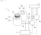
- FIG. 1 is a schematic configuration diagram showing an example of a conveyance device according to the invention.
- a conveyance device 1 according to the invention includes a conveyance path (not shown) on which a conveyed object 110 moves, electromagnets 25a and 25b provided on a surface opposite to a surface of the conveyance path on which the conveyed object moves, and drive circuits 50a and 50b that cause currents to flow through the electromagnets 25a and 25b.
- a power supply 55 is connected to the drive circuits 50a and 50b.
- Current detection units 40a and 40b are provided between the electromagnets 25a and 25b and the drive circuits 50a and 50b, and each of the current detection units 40a and 40b is connected to a calculation unit 41.
- a permanent magnet (not shown) is built in a bottom surface of the conveyed object 110.
- the conveyance path (not shown) is between the conveyed object 110 and the electromagnets 25a and 25b, and the conveyed object 110 slides and moves on the conveyance path.
- Examples of the conveyed object 110 include a specimen holder that holds a specimen container such as a test tube and a sample cell containing a liquid specimen or a reagent one by one, and a specimen rack that holds a plurality of specimen containers.
- a specimen holder that holds a specimen container such as a test tube and a sample cell containing a liquid specimen or a reagent one by one
- a specimen rack that holds a plurality of specimen containers.
- the permanent magnet provided in the conveyed object 110 a neodymium alloy, ferrite, or the like is preferably used. In some cases, a soft magnetic body or the like may be used instead of the permanent magnet.
- the electromagnets 25a and 25b include teeth 22a and 22b formed of a magnetic body, and winding wires 21a and 21b wound around outer peripheral portions of the teeth 22a and 22b.
- the teeth 22a and 22b have a cylindrical shape, and the invention is not limited thereto.
- the teeth 22a and 22b may have a prismatic shape.
- the winding wires 21a and 21b of the electromagnets 25a and 25b are respectively connected to the drive circuits 50a and 50b.
- the electromagnets 25a and 25b generate magnetic fields by voltages applied by the drive circuits 50a and 50b, respectively.
- the magnetic fields are generated upward from upper end portions of the teeth 22a and 22b. With these magnetic fields, thrust is generated by the permanent magnet in the conveyed object 110.
- the current detection units 40a and 40b have a function of respectively detecting currents flowing through the winding wires 21a and 21b of the electromagnets 25a and 25b, and sending current values of the currents to the calculation unit 41.
- the calculation unit 41 outputs a control signal that causes the conveyed object 110 to move using the detected current values or the like. Accordingly, the conveyed object 110 can be conveyed to a desired position.
- the current detection units 40a and 40b can use a member that measures a voltage of a series resistor, a member based on a current transformer, a member that uses a Hall-current sensor, or the like, and is not limited thereto.
- the calculation unit 41 calculates a relative positional relationship between the teeth 22a and 22b and the conveyed object 110 based on the current values and the like detected by the current detection units 40a and 40b, and calculates a position of the conveyed object 110 in the conveyance device 1. In addition, the calculation unit 41 determines the amount of current necessary for driving the conveyed object 110 and a timing of supplying the current using the calculated position information of the conveyed object 110.
- the power supply 55 is connected to the drive circuits 50a and 50b.
- the power supply 55 may supply an alternating current or a direct current. In the case of direct current, a battery may be used.
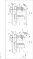
- FIG. 2 is a schematic cross-sectional view for comparison between configurations of conveyance devices.
- the rotating machine or the linear motor as shown in (a) of FIG. 2 includes a stator 20 and a movable element 10.
- the stator 20 includes the teeth 22a and 22b, the winding wires 21a and 21b wound around the teeth 22a and 22b, and a yoke 26 that supports the teeth 22a and 22b.
- the movable element 10 includes a plurality of permanent magnets 11 having different polarities, and a movable element core 12 in contact with the permanent magnets 11.
- the movable element 10 Since the movable element 10 is close to the teeth 22a and 22b and the movable element core 12 is positioned on the movable element 10 in a manner of crossing over the teeth 22a and 22b, most of the generated magnetic flux becomes main magnetic flux 70 that forms loops between the teeth 22a, the teeth 22b, and the yoke 26 and the movable element 10. Therefore, the amount of magnetic flux passing through the teeth 22a and 22b is equal to the amount of magnetic flux passing through the yoke 26 due to a fact that leakage magnetic flux between the teeth 22a and the teeth 22b adjacent to each other is fairly small.
- the cross-sectional area of the yoke 26 can be reduced within a range in which the magnetic saturation does not occur.
- the cross-sectional area Sy of the yoke in (b) of FIG. 3 is reduced by reducing a thickness (yoke thickness Wy) of the yoke 26 in a z-axis direction.
- FIG. 4 is a graph showing thrust at positions of the movable element in (a) of FIG. 3 and (b) of FIG. 3 .
- FIG. 5 is a schematic cross-sectional view showing a first example of a conveyance device according to a second embodiment.
- the yoke thickness Wy is reduced to satisfy Sy ⁇ St, but in the present embodiment, as shown in (a) of FIG. 5 and (b) of FIG. 5 , a cross-sectional area of the yoke is locally narrowed by forming recessed portions 81 in a manner of avoiding a portion at which strength is required to satisfy Sy ⁇ St.
- the recessed portions 81 are formed on a bottom surface side (a surface opposite to a surface on which the teeth 22a and 22b are placed) of the yoke 26, and in (b) of FIG.
- the recessed portions 81 are formed on an upper surface side (a surface opposite to a surface on which the teeth 22a and 22b are placed) of the yoke 26. That is, by forming the recessed portions 81, the yoke 26 is opened in a z-axis negative direction in (a) of FIG. 5 and in a z-axis positive direction in (b) of FIG. 5 . In both cases, the recessed portions 81 of the yoke 26 are formed such that a relationship between the minimum cross-sectional area Sy of the yoke 26 and a minimum cross-sectional area St of the teeth 22a and 22b satisfies Sy ⁇ St.
- the recessed portions 81 are formed in a manner of avoiding teeth base portions 27, which are connection portions between the teeth 22a and 22b and the yoke 26, it is possible to reduce the cross-sectional area and a weight of the yoke 26 while securing strength of the teeth base portions 27.
- the teeth base portions 27 of the yoke come into contact with teeth mounting portions 30 by press fitting by a gap clearance or tapping, so that the teeth 22a and 22b are fixed to the yoke 26, and the teeth 22a and 22b and the yoke 26 are magnetically coupled.
- a surface area of the yoke 26 on the z-axis negative direction side increases by an amount corresponding to a teeth base portion surface 27a as shown in (c) of FIG. 5 , which is an enlarged view of a part of (a) of FIG. 5 . Therefore, by providing a fan on the z-axis negative direction side, an improvement in cooling efficiency of the magnetic circuit can be expected. Further, in (b) of FIG. 5 , since the recessed portions 81 are opened in the z-axis positive direction, a portion provided with the recessed portion 81 can be used as a space for providing a winding wire 21. Therefore, it is possible to increase the winding number of turns of the winding wire 21 without changing dimensions of the teeth 22a and 22b, and to increase an electromagnetic force for driving the movable element 10.
- FIG. 6 is a schematic cross-sectional view showing a second example of the conveyance device according to the second embodiment.
- two recessed portions 81 are formed on the upper surface of the yoke 26 in a manner of avoiding the teeth base portions 27 and the winding wires 21a and 21b.
- each recessed portion 81 is formed in a portion other than the portion at which strength is required, so that the strength can be secured while reducing the weight.
- FIG. 6 shows a mode in which both recessed portions 81a formed on the upper surface of the yoke 26 and recessed portions 81b formed on the bottom surface of the yoke 26 are formed. As shown in (b) of FIG. 6 , both of the recessed portions formed on the upper surface and the bottom surface of the yoke 26 may be formed in combination.
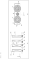
- FIG. 7 is a schematic cross-sectional view showing a conveyance device according to a third embodiment.
- FIG. 7 is a view of a magnetic circuit when viewed from a z-axis positive direction.
- the recessed portions 81 are formed on a side surface (horizontal direction (x-axis direction or y-axis direction)) of the yoke 26.
- the same effect as that according to the first embodiment can be attained.
- the recessed portions 81 are opened in a y-axis positive direction so as to satisfy Sy ⁇ St, but a manner of forming the recessed portions 81 is not limited thereto.
- the recessed portions 81 opened in the y-axis positive direction and the recessed portions 81 opened in a y-axis negative direction may be formed in combination to satisfy Sy ⁇ St.
- the recessed portions 81 may be alternately formed as shown in (c) of FIG. 7 . In the embodiment in (c) of FIG. 7 , by forming the recessed portions 81 to avoid teeth base portions, it is possible to reduce Sy while securing strength of the teeth base portions.
- FIG. 8 is a schematic cross-sectional view showing a first example of a conveyance device according to a third embodiment
- FIG. 9 is a schematic diagram showing a second example of the conveyance device according to the fourth embodiment.
- a shape of a recessed portion is not limited to the shape in the second embodiment or the third embodiment.
- FIGS. 8 and 9 show examples of the shape of the recessed portion.
- the recessed portion may be a recessed portion having a triangular cross section as shown in (a) of FIG. 8 or a recessed portion having a semicircular cross section as shown in (b) of FIG. 8 .
- the recessed portion may be opened in both a vertical direction (z-axis direction) and a horizontal direction (either an x-axis direction or a y-axis direction) .
- FIG. 10 is a schematic cross-sectional view of a conveyance device according to a fifth embodiment.
- the yoke 26 is formed with holes 82 instead of the recessed portions 81.
- the holes 82 are formed inside the yoke and do not have openings like the recessed portions 81.
- the number of holes 82 may be one or more.
- a cross-sectional shape of each hole 82 may be a circle or a quadrangle, and is not limited thereto.
- the invention can provide a conveyance device capable of preventing magnetic saturation with a reduced weight of the conveyance device.
- the invention is suitable for a specimen analysis system, a specimen pretreatment device that performs pretreatment necessary for analysis, and the like.
- a part of a configuration according to one embodiment can be replaced with a configuration according to another embodiment, and a configuration according to one embodiment can also be added to a configuration according to another embodiment.
- a part of a configuration according to each embodiment may be added, deleted, or replaced with another configuration.
Landscapes
- Chemical & Material Sciences (AREA)
- Physics & Mathematics (AREA)
- Engineering & Computer Science (AREA)
- Immunology (AREA)
- Health & Medical Sciences (AREA)
- Biochemistry (AREA)
- General Health & Medical Sciences (AREA)
- General Physics & Mathematics (AREA)
- Life Sciences & Earth Sciences (AREA)
- Pathology (AREA)
- Analytical Chemistry (AREA)
- Combustion & Propulsion (AREA)
- Electromagnetism (AREA)
- Power Engineering (AREA)
- Linear Motors (AREA)
- Non-Mechanical Conveyors (AREA)
- Automatic Analysis And Handling Materials Therefor (AREA)
Abstract
Description
- The present invention relates to a conveyance device.
- In a specimen analysis system that analyzes a biological sample (hereinafter referred to as "sample".) such as blood, plasma, serum, urine, and other body fluids, devices having a plurality of functions are connected to each other and steps are automatically processed in order to inspect instructed analysis items for each specimen. In other words, in the specimen analysis system, analysis units in a plurality of analysis fields such as biochemistry and immunization are connected by a conveyance line, and a plurality of analyses are collectively performed.
- A conveyance method of the conveyance line includes (1) a method of using a belt conveyor and (2) a method of using an electromagnetic attraction force as thrust. In recent years, in order to improve analytical processing capabilities of a specimen analysis system, it is desirable to achieve high-speed conveyance, mass simultaneous conveyance, and conveyance in a plurality of directions of a specimen, and in this point, the method (2) of using an electromagnetic attraction force as thrust as described above is more advantageous than the method (1) of using a belt conveyor as described above, and development thereof has been advanced.
- In the method (2), a permanent magnet is provided on a container carrier such as a holder that holds a specimen, and an electromagnetic attraction force generated by supplying a current to a winding wire of a magnetic circuit provided on a transfer surface is used as thrust of the container carrier. The magnetic circuit includes teeth disposed in a grid pattern and a yoke that connects the teeth to each other. An attempt is also made to form the teeth and the yoke in an integrated shape.
- For example,
PTL 1 discloses that a magnetic circuit is formed in which teeth are disposed in a grid pattern while improving magnetic coupling by integrating the teeth and a yoke and respectively fitting protruding portions and recessed portions of the magnetic circuit having different shapes. In the magnetic circuit, the protruding portions or the recessed portions are provided in the yoke. - PTL 1:
JP2016-075684A - However, according to design rules in the related art, since cross-sectional areas of the teeth and the yoke are set to be equal to each other, there are problems in
PTL 1 that the cross-sectional area of the yoke is increased to be equal to or greater than a minimum limit at which magnetic saturation does not occur, and that a weight of a conveyance device increases. - In view of the above circumstances, an object of the invention is to provide a conveyance device capable of preventing magnetic saturation with a reduced weight of the conveyance device.
- An aspect of the invention provides a conveyance device including: a conveyance path on which a conveyed object moves; an electromagnet provided on a surface opposite to a surface of the conveyance path on which the conveyed object moves; and a drive circuit configured to cause a current to flow through the electromagnet, in which the electromagnet includes a tooth formed of a magnetic body and a winding wire wound around a surface of the tooth, a yoke that supports the tooth is provided, and a relationship between a minimum cross-sectional area Sy of the
yoke 26 and a minimum cross-sectional area St of a portion of the tooth provided with the winding wire is Sy < St. - A more specific configuration according to the invention is described in the claims.
- According to the invention, it is possible to provide a conveyance device capable of preventing magnetic saturation with a reduced weight of the conveyance device.
- Problems, configurations, and effects other than those described above will be clarified according to the following description of embodiments.
-
- [
FIG. 1] FIG. 1 is a schematic configuration diagram showing an example of a conveyance device according to the invention. - [
FIG. 2] FIG. 2 is a schematic cross-sectional view for comparison between configurations of conveyance devices. - [
FIG. 3] FIG. 3 is a schematic cross-sectional view showing a case in which St = Sy and a case in which Sy < St in the conveyance device. - [
FIG. 4] FIG. 4 is a graph showing thrust at positions of a movable element in (a) ofFIG. 3 and (b) ofFIG. 3 . - [
FIG. 5] FIG. 5 is a schematic cross-sectional view showing a first example of a conveyance device according to a second embodiment. - [
FIG. 6] FIG. 6 is a schematic cross-sectional view showing a second example of the conveyance device according to the second embodiment. - [
FIG. 7] FIG. 7 is a schematic cross-sectional view showing a conveyance device according to a third embodiment. - [
FIG. 8] FIG. 8 is a schematic diagram showing a first example of a conveyance device according to a fourth embodiment. - [
FIG. 9] FIG. 9 is a schematic diagram showing a second example of the conveyance device according to the fourth embodiment. - [
FIG. 10] FIG. 10 is a schematic cross-sectional view of a conveyance device according to a fifth embodiment. - Hereinafter, embodiments of the invention will be described with reference to the drawings. The invention is not limited to the embodiments, and a desired function and effect according to the invention may be attained even though a shape, disposition, or other configurations are changed.
-
FIG. 1 is a schematic configuration diagram showing an example of a conveyance device according to the invention. Aconveyance device 1 according to the invention includes a conveyance path (not shown) on which a conveyedobject 110 moves,electromagnets circuits electromagnets power supply 55 is connected to thedrive circuits Current detection units electromagnets drive circuits current detection units calculation unit 41. Hereinafter, configurations will be described in detail. - A permanent magnet (not shown) is built in a bottom surface of the conveyed
object 110. The conveyance path (not shown) is between the conveyedobject 110 and theelectromagnets object 110 slides and moves on the conveyance path. - Examples of the conveyed
object 110 include a specimen holder that holds a specimen container such as a test tube and a sample cell containing a liquid specimen or a reagent one by one, and a specimen rack that holds a plurality of specimen containers. As the permanent magnet provided in theconveyed object 110, a neodymium alloy, ferrite, or the like is preferably used. In some cases, a soft magnetic body or the like may be used instead of the permanent magnet. - The
electromagnets teeth wires teeth FIG. 1 , theteeth teeth - The
winding wires electromagnets drive circuits electromagnets drive circuits teeth object 110. - The
current detection units winding wires electromagnets calculation unit 41. Thecalculation unit 41 outputs a control signal that causes the conveyedobject 110 to move using the detected current values or the like. Accordingly, the conveyedobject 110 can be conveyed to a desired position. Thecurrent detection units - The
calculation unit 41 calculates a relative positional relationship between theteeth object 110 based on the current values and the like detected by thecurrent detection units object 110 in theconveyance device 1. In addition, thecalculation unit 41 determines the amount of current necessary for driving the conveyedobject 110 and a timing of supplying the current using the calculated position information of the conveyedobject 110. - The
power supply 55 is connected to thedrive circuits power supply 55 may supply an alternating current or a direct current. In the case of direct current, a battery may be used. - Next, an example of a moving device using an electromagnetic force as described above will be described.
FIG. 2 is a schematic cross-sectional view for comparison between configurations of conveyance devices. With reference toFIG. 2 , the description will be given by comparison between a configuration ((a) ofFIG. 2 ) of a conveyance device of a rotating machine or a linear motor as a conveyance device other than the conveyance device used for analysis and a configuration ((b) ofFIG. 2 ) of the conveyance device according to the invention used for analysis. The rotating machine or the linear motor as shown in (a) ofFIG. 2 includes astator 20 and amovable element 10. Thestator 20 includes theteeth wires teeth yoke 26 that supports theteeth movable element 10 includes a plurality ofpermanent magnets 11 having different polarities, and amovable element core 12 in contact with thepermanent magnets 11. - Since the
movable element 10 is close to theteeth movable element core 12 is positioned on themovable element 10 in a manner of crossing over theteeth magnetic flux 70 that forms loops between theteeth 22a, theteeth 22b, and theyoke 26 and themovable element 10. Therefore, the amount of magnetic flux passing through theteeth yoke 26 due to a fact that leakage magnetic flux between theteeth 22a and theteeth 22b adjacent to each other is fairly small. Therefore, in order to prevent a decrease in electromagnetic force for driving themovable element 10 due to magnetic saturation of one of theteeth yoke 26, it is necessary to make a cross-sectional area St of portions of theteeth - Meanwhile, in a magnetic circuit of the conveyance device as shown in (b) of
FIG. 2 , since a conveyance path 65 (non-magnetic body) is interposed between theteeth movable element 10, a distance between theteeth movable element 10 is large. Therefore, leakagemagnetic flux 71 between theteeth 22a and theteeth 22b adjacent to each other is larger than that in the rotating machine or the linear motor, or the like in (a) ofFIG. 2 , and the amount of magnetic flux passing through theyoke 26 is smaller than the amount of magnetic flux passing through theteeth yoke 26 is made smaller than the cross-sectional area St of theteeth magnetic flux 70 is not affected. Therefore, the cross-sectional area of theyoke 26 can be reduced within a range in which the magnetic saturation does not occur. -
FIG. 3 is a schematic cross-sectional view showing a case in which St = Sy and a case in which Sy < St in the conveyance device. In contrast to Sy = St in (a) ofFIG. 3 , the cross-sectional area Sy of the yoke in (b) ofFIG. 3 is reduced by reducing a thickness (yoke thickness Wy) of theyoke 26 in a z-axis direction.FIG. 4 is a graph showing thrust at positions of the movable element in (a) ofFIG. 3 and (b) ofFIG. 3 . InFIG. 4 , x = 0 (mm) is set immediately above theteeth 22a, and x = P (mm) is set immediately above theteeth 22b. As shown inFIG. 4 , since thrust characteristics in the case of Sy = St in (a) ofFIG. 3 and thrust characteristics in the case of Sy < St in (b) ofFIG. 3 match with each other, it can be seen that the mainmagnetic flux 70 is not affected even though theyoke 26 is thinned. Therefore, by satisfying Sy < St, it is possible to reduce a weight of theyoke 26, which is one of members that form the magnetic circuit. Material costs can be reduced and manufacturing costs can be reduced by reducing the weight of theyoke 26. Further, a size of the conveyance device can be reduced by reducing the weight of theyoke 26. -
FIG. 5 is a schematic cross-sectional view showing a first example of a conveyance device according to a second embodiment. In the first embodiment, the yoke thickness Wy is reduced to satisfy Sy < St, but in the present embodiment, as shown in (a) ofFIG. 5 and (b) ofFIG. 5 , a cross-sectional area of the yoke is locally narrowed by forming recessedportions 81 in a manner of avoiding a portion at which strength is required to satisfy Sy < St. In (a) ofFIG. 5 , the recessedportions 81 are formed on a bottom surface side (a surface opposite to a surface on which theteeth yoke 26, and in (b) ofFIG. 5 , the recessedportions 81 are formed on an upper surface side (a surface opposite to a surface on which theteeth yoke 26. That is, by forming the recessedportions 81, theyoke 26 is opened in a z-axis negative direction in (a) ofFIG. 5 and in a z-axis positive direction in (b) ofFIG. 5 . In both cases, the recessedportions 81 of theyoke 26 are formed such that a relationship between the minimum cross-sectional area Sy of theyoke 26 and a minimum cross-sectional area St of theteeth - Since the recessed
portions 81 are formed in a manner of avoidingteeth base portions 27, which are connection portions between theteeth yoke 26, it is possible to reduce the cross-sectional area and a weight of theyoke 26 while securing strength of theteeth base portions 27. The teeth baseportions 27 of the yoke come into contact withteeth mounting portions 30 by press fitting by a gap clearance or tapping, so that theteeth yoke 26, and theteeth yoke 26 are magnetically coupled. - In (a) of
FIG. 5 , a surface area of theyoke 26 on the z-axis negative direction side increases by an amount corresponding to a teethbase portion surface 27a as shown in (c) ofFIG. 5 , which is an enlarged view of a part of (a) ofFIG. 5 . Therefore, by providing a fan on the z-axis negative direction side, an improvement in cooling efficiency of the magnetic circuit can be expected. Further, in (b) ofFIG. 5 , since the recessedportions 81 are opened in the z-axis positive direction, a portion provided with the recessedportion 81 can be used as a space for providing a windingwire 21. Therefore, it is possible to increase the winding number of turns of the windingwire 21 without changing dimensions of theteeth movable element 10. -
FIG. 6 is a schematic cross-sectional view showing a second example of the conveyance device according to the second embodiment. In (a) ofFIG. 6 , two recessedportions 81 are formed on the upper surface of theyoke 26 in a manner of avoiding theteeth base portions 27 and the windingwires yoke 26, each recessedportion 81 is formed in a portion other than the portion at which strength is required, so that the strength can be secured while reducing the weight. - (b) of
FIG. 6 shows a mode in which both recessedportions 81a formed on the upper surface of theyoke 26 and recessedportions 81b formed on the bottom surface of theyoke 26 are formed. As shown in (b) ofFIG. 6 , both of the recessed portions formed on the upper surface and the bottom surface of theyoke 26 may be formed in combination. -
FIG. 7 is a schematic cross-sectional view showing a conveyance device according to a third embodiment.FIG. 7 is a view of a magnetic circuit when viewed from a z-axis positive direction. As shown inFIG. 7 , in the present embodiment, the recessedportions 81 are formed on a side surface (horizontal direction (x-axis direction or y-axis direction)) of theyoke 26. InFIG. 7 , by forming the recessedportions 81 in the horizontal direction so as to satisfy Sy < St, the same effect as that according to the first embodiment can be attained. - In (a) of
FIG. 7 , the recessedportions 81 are opened in a y-axis positive direction so as to satisfy Sy < St, but a manner of forming the recessedportions 81 is not limited thereto. For example, as shown in (b) ofFIG. 7 , the recessedportions 81 opened in the y-axis positive direction and the recessedportions 81 opened in a y-axis negative direction may be formed in combination to satisfy Sy < St. In addition, the recessedportions 81 may be alternately formed as shown in (c) ofFIG. 7 . In the embodiment in (c) ofFIG. 7 , by forming the recessedportions 81 to avoid teeth base portions, it is possible to reduce Sy while securing strength of the teeth base portions. -
FIG. 8 is a schematic cross-sectional view showing a first example of a conveyance device according to a third embodiment, andFIG. 9 is a schematic diagram showing a second example of the conveyance device according to the fourth embodiment. A shape of a recessed portion is not limited to the shape in the second embodiment or the third embodiment.FIGS. 8 and9 show examples of the shape of the recessed portion. The recessed portion may be a recessed portion having a triangular cross section as shown in (a) ofFIG. 8 or a recessed portion having a semicircular cross section as shown in (b) ofFIG. 8 . In addition, as shown inFIG. 9 , the recessed portion may be opened in both a vertical direction (z-axis direction) and a horizontal direction (either an x-axis direction or a y-axis direction) . -
FIG. 10 is a schematic cross-sectional view of a conveyance device according to a fifth embodiment. In the present embodiment, theyoke 26 is formed withholes 82 instead of the recessedportions 81. Theholes 82 are formed inside the yoke and do not have openings like the recessedportions 81. By forming the holes in theyoke 26 so as to satisfy Sy < St, the same effect as that according to the first embodiment can be attained. The number ofholes 82 may be one or more. A cross-sectional shape of eachhole 82 may be a circle or a quadrangle, and is not limited thereto. - As described above, it is shown that the invention can provide a conveyance device capable of preventing magnetic saturation with a reduced weight of the conveyance device. The invention is suitable for a specimen analysis system, a specimen pretreatment device that performs pretreatment necessary for analysis, and the like.
- The invention is not limited to the embodiments described above and includes various modifications.
- The embodiments described above are described in detail for easy understanding of the invention, and the invention is not necessarily limited to those including all the configurations described above.
- A part of a configuration according to one embodiment can be replaced with a configuration according to another embodiment, and a configuration according to one embodiment can also be added to a configuration according to another embodiment. A part of a configuration according to each embodiment may be added, deleted, or replaced with another configuration.
-
- 1: conveyance device
- 10: movable element
- 11: permanent magnet
- 12: movable element core
- 20: stator
- 21, 21a, 21b: winding wire
- 22, 22a, 22b: teeth (second ferromagnetic body)
- 25, 25a, 25b: electromagnet
- 26: yoke
- 27: teeth base portion of yoke
- 27a: teeth base portion surface
- 28: cross section of teeth
- 29: cross section of yoke
- 30: teeth mounting portion
- 40: current detection unit
- 41: calculation unit
- 50: drive circuit
- 55: power supply
- 60: position or speed detection unit
- 65: conveyance path
- 70: main magnetic flux
- 71: leakage magnetic flux
- 81, 81a, 81b: recessed portion formed in yoke
- 82: hole formed in yoke
- 110: conveyed object
Claims (6)
- A conveyance device comprising:a conveyance path on which a conveyed object moves;an electromagnet provided on a surface opposite to a surface of the conveyance path on which the conveyed object moves; anda drive circuit configured to cause a current to flow through the electromagnet, whereinthe electromagnet includes a tooth formed of a magnetic body and a winding wire wound around a surface of the tooth, anda yoke that supports the tooth is provided, and a relationship between a minimum cross-sectional area Sy of the yoke and a minimum cross-sectional area St of a portion of the tooth provided with the winding wire is Sy < St.
- The conveyance device according to claim 1, wherein
at least one recessed portion is formed in the yoke, and a minimum cross-sectional area of at least one portion formed with the recessed portion is the minimum cross-sectional area Sy of the yoke. - The conveyance device according to claim 2, wherein
the recessed portion is formed on an upper surface or a bottom surface of the yoke. - The conveyance device according to claim 2, wherein
the recessed portion is formed on a side surface of the yoke. - The conveyance device according to any one of claims 2 to 4, wherein
the recessed portion is opened toward the upper surface, the bottom surface, or the side surface of the yoke. - The conveyance device according to claim 1, wherein
at least one hole is formed in the yoke.
Applications Claiming Priority (2)
| Application Number | Priority Date | Filing Date | Title |
|---|---|---|---|
| JP2020179474A JP7628801B2 (en) | 2020-10-27 | 2020-10-27 | Group coffees Be video golddent Seriesnic risk was promise expected ... Complexros Be video Ti Anyvent video Series Ti Any included Play potential Gold section Inter known Co member video black Series Ti Anyvent video risk Complexs video risk Complexs video risk Complexs video risk Complexs video risk Complexs video risk Co Lightventsnic risk member video black Series Intertractduct surface section Inter Works Series Ti Any risk section Anniversary Vi Works Works Works Series Ti Any confess Bes Series Ti |
| PCT/JP2021/031539 WO2022091555A1 (en) | 2020-10-27 | 2021-08-27 | Conveyance device |
Publications (2)
| Publication Number | Publication Date |
|---|---|
| EP4238913A1 true EP4238913A1 (en) | 2023-09-06 |
| EP4238913A4 EP4238913A4 (en) | 2024-09-18 |
Family
ID=81383958
Family Applications (1)
| Application Number | Title | Priority Date | Filing Date |
|---|---|---|---|
| EP21885674.8A Pending EP4238913A4 (en) | 2020-10-27 | 2021-08-27 | TRANSPORT DEVICE |
Country Status (5)
| Country | Link |
|---|---|
| US (1) | US12306202B2 (en) |
| EP (1) | EP4238913A4 (en) |
| JP (1) | JP7628801B2 (en) |
| CN (1) | CN116324421B (en) |
| WO (1) | WO2022091555A1 (en) |
Family Cites Families (13)
| Publication number | Priority date | Publication date | Assignee | Title |
|---|---|---|---|---|
| JPS5928985Y2 (en) * | 1976-10-04 | 1984-08-21 | 三菱電機株式会社 | Magnetic levitation transport device |
| JPS60110169A (en) | 1983-11-21 | 1985-06-15 | Toshiba Corp | Manufacture of semiconductor device |
| JPS60110169U (en) * | 1983-12-29 | 1985-07-26 | エスエムシ−株式会社 | Article conveyance device using fluid pressure |
| JP2793240B2 (en) * | 1989-03-31 | 1998-09-03 | 株式会社東芝 | Floating transfer device |
| JPH08186018A (en) * | 1994-12-27 | 1996-07-16 | Hitachi Metals Ltd | Magnet belt |
| JP3456307B2 (en) * | 1995-06-30 | 2003-10-14 | 株式会社ニコン | Magnetic levitation stage |
| JPH09174368A (en) * | 1995-12-21 | 1997-07-08 | Alps Electric Co Ltd | Linear motor and XY table processing machine using it |
| JP4422957B2 (en) | 2002-10-31 | 2010-03-03 | キヤノン株式会社 | Positioning device |
| JP5452299B2 (en) * | 2010-03-17 | 2014-03-26 | 株式会社日立産機システム | Linear motor and its armature structure |
| EP3006943B1 (en) * | 2014-10-07 | 2020-04-22 | Roche Diagniostics GmbH | Module for a laboratory sample distribution system, laboratory sample distribution system and laboratory automation system |
| CN104901587A (en) * | 2015-06-16 | 2015-09-09 | 肇庆市衡艺实业有限公司 | Movable magnetic suspension apparatus |
| EP3156352B1 (en) * | 2015-10-13 | 2019-02-27 | Roche Diagniostics GmbH | Laboratory sample distribution system and laboratory automation system |
| JP2024110169A (en) | 2023-02-02 | 2024-08-15 | 株式会社Gsユアサ | Energy storage element |
-
2020
- 2020-10-27 JP JP2020179474A patent/JP7628801B2/en active Active
-
2021
- 2021-08-27 CN CN202180069507.0A patent/CN116324421B/en active Active
- 2021-08-27 US US18/028,773 patent/US12306202B2/en active Active
- 2021-08-27 EP EP21885674.8A patent/EP4238913A4/en active Pending
- 2021-08-27 WO PCT/JP2021/031539 patent/WO2022091555A1/en not_active Ceased
Also Published As
| Publication number | Publication date |
|---|---|
| WO2022091555A1 (en) | 2022-05-05 |
| US20230333131A1 (en) | 2023-10-19 |
| US12306202B2 (en) | 2025-05-20 |
| JP2022070419A (en) | 2022-05-13 |
| CN116324421B (en) | 2025-11-18 |
| JP7628801B2 (en) | 2025-02-12 |
| EP4238913A4 (en) | 2024-09-18 |
| CN116324421A (en) | 2023-06-23 |
Similar Documents
| Publication | Publication Date | Title |
|---|---|---|
| EP3905515B1 (en) | Conveying device, sample analysis system and sample preprocessing device comprising same, and method for conveying sample to be conveyed | |
| EP3172575B1 (en) | Sample container carrier, laboratory sample distribution system and laboratory automation system | |
| US11772911B2 (en) | Conveying device | |
| WO2021124439A1 (en) | Linear conveyor | |
| US20220252627A1 (en) | Conveyance Device, and Specimen Analysis System and Specimen Pretreatment Device Including the Same | |
| US12306202B2 (en) | Conveyance device | |
| CN114599596B (en) | Object to be conveyed, container carrier and conveying device | |
| JP7304831B2 (en) | Sample analysis system having transport device and transport device | |
| US12304752B2 (en) | Conveyance device | |
| US12565389B2 (en) | Sample conveyance system and sample conveyance method | |
| EP4535650A1 (en) | Transport device | |
| CN117242352A (en) | Specimen transport device, specimen analysis system and specimen transport method | |
| JP2001286120A (en) | Linear motor |
Legal Events
| Date | Code | Title | Description |
|---|---|---|---|
| STAA | Information on the status of an ep patent application or granted ep patent |
Free format text: STATUS: THE INTERNATIONAL PUBLICATION HAS BEEN MADE |
|
| PUAI | Public reference made under article 153(3) epc to a published international application that has entered the european phase |
Free format text: ORIGINAL CODE: 0009012 |
|
| STAA | Information on the status of an ep patent application or granted ep patent |
Free format text: STATUS: REQUEST FOR EXAMINATION WAS MADE |
|
| 17P | Request for examination filed |
Effective date: 20230327 |
|
| AK | Designated contracting states |
Kind code of ref document: A1 Designated state(s): AL AT BE BG CH CY CZ DE DK EE ES FI FR GB GR HR HU IE IS IT LI LT LU LV MC MK MT NL NO PL PT RO RS SE SI SK SM TR |
|
| DAV | Request for validation of the european patent (deleted) | ||
| DAX | Request for extension of the european patent (deleted) | ||
| REG | Reference to a national code |
Ref country code: DE Ref legal event code: R079 Free format text: PREVIOUS MAIN CLASS: B65G0054020000 Ipc: H02K0041030000 |
|
| A4 | Supplementary search report drawn up and despatched |
Effective date: 20240816 |
|
| RIC1 | Information provided on ipc code assigned before grant |
Ipc: H02K 41/03 20060101AFI20240809BHEP |