EP4238870A1 - Aircraft propulsion system - Google Patents
Aircraft propulsion system Download PDFInfo
- Publication number
- EP4238870A1 EP4238870A1 EP23154920.5A EP23154920A EP4238870A1 EP 4238870 A1 EP4238870 A1 EP 4238870A1 EP 23154920 A EP23154920 A EP 23154920A EP 4238870 A1 EP4238870 A1 EP 4238870A1
- Authority
- EP
- European Patent Office
- Prior art keywords
- engine
- engines
- electrical
- fuel flow
- electrical machine
- Prior art date
- Legal status (The legal status is an assumption and is not a legal conclusion. Google has not performed a legal analysis and makes no representation as to the accuracy of the status listed.)
- Granted
Links
Images






Classifications
-
- B—PERFORMING OPERATIONS; TRANSPORTING
- B64—AIRCRAFT; AVIATION; COSMONAUTICS
- B64D—EQUIPMENT FOR FITTING IN OR TO AIRCRAFT; FLIGHT SUITS; PARACHUTES; ARRANGEMENT OR MOUNTING OF POWER PLANTS OR PROPULSION TRANSMISSIONS IN AIRCRAFT
- B64D27/00—Arrangement or mounting of power plants in aircraft; Aircraft characterised by the type or position of power plants
- B64D27/02—Aircraft characterised by the type or position of power plants
- B64D27/10—Aircraft characterised by the type or position of power plants of gas-turbine type
-
- B—PERFORMING OPERATIONS; TRANSPORTING
- B64—AIRCRAFT; AVIATION; COSMONAUTICS
- B64D—EQUIPMENT FOR FITTING IN OR TO AIRCRAFT; FLIGHT SUITS; PARACHUTES; ARRANGEMENT OR MOUNTING OF POWER PLANTS OR PROPULSION TRANSMISSIONS IN AIRCRAFT
- B64D27/00—Arrangement or mounting of power plants in aircraft; Aircraft characterised by the type or position of power plants
- B64D27/02—Aircraft characterised by the type or position of power plants
- B64D27/30—Aircraft characterised by electric power plants
- B64D27/31—Aircraft characterised by electric power plants within, or attached to, wings
-
- B—PERFORMING OPERATIONS; TRANSPORTING
- B64—AIRCRAFT; AVIATION; COSMONAUTICS
- B64D—EQUIPMENT FOR FITTING IN OR TO AIRCRAFT; FLIGHT SUITS; PARACHUTES; ARRANGEMENT OR MOUNTING OF POWER PLANTS OR PROPULSION TRANSMISSIONS IN AIRCRAFT
- B64D27/00—Arrangement or mounting of power plants in aircraft; Aircraft characterised by the type or position of power plants
- B64D27/02—Aircraft characterised by the type or position of power plants
- B64D27/30—Aircraft characterised by electric power plants
- B64D27/33—Hybrid electric aircraft
-
- B—PERFORMING OPERATIONS; TRANSPORTING
- B64—AIRCRAFT; AVIATION; COSMONAUTICS
- B64D—EQUIPMENT FOR FITTING IN OR TO AIRCRAFT; FLIGHT SUITS; PARACHUTES; ARRANGEMENT OR MOUNTING OF POWER PLANTS OR PROPULSION TRANSMISSIONS IN AIRCRAFT
- B64D31/00—Power plant control systems; Arrangement of power plant control systems in aircraft
- B64D31/16—Power plant control systems; Arrangement of power plant control systems in aircraft for electric power plants
- B64D31/18—Power plant control systems; Arrangement of power plant control systems in aircraft for electric power plants for hybrid-electric power plants
-
- F—MECHANICAL ENGINEERING; LIGHTING; HEATING; WEAPONS; BLASTING
- F02—COMBUSTION ENGINES; HOT-GAS OR COMBUSTION-PRODUCT ENGINE PLANTS
- F02C—GAS-TURBINE PLANTS; AIR INTAKES FOR JET-PROPULSION PLANTS; CONTROLLING FUEL SUPPLY IN AIR-BREATHING JET-PROPULSION PLANTS
- F02C6/00—Plural gas-turbine plants; Combinations of gas-turbine plants with other apparatus; Adaptations of gas-turbine plants for special use
- F02C6/20—Adaptations of gas-turbine plants for driving vehicles
-
- F—MECHANICAL ENGINEERING; LIGHTING; HEATING; WEAPONS; BLASTING
- F02—COMBUSTION ENGINES; HOT-GAS OR COMBUSTION-PRODUCT ENGINE PLANTS
- F02C—GAS-TURBINE PLANTS; AIR INTAKES FOR JET-PROPULSION PLANTS; CONTROLLING FUEL SUPPLY IN AIR-BREATHING JET-PROPULSION PLANTS
- F02C9/00—Controlling gas-turbine plants; Controlling fuel supply in air- breathing jet-propulsion plants
- F02C9/26—Control of fuel supply
- F02C9/28—Regulating systems responsive to plant or ambient parameters, e.g. temperature, pressure, rotor speed
-
- F—MECHANICAL ENGINEERING; LIGHTING; HEATING; WEAPONS; BLASTING
- F02—COMBUSTION ENGINES; HOT-GAS OR COMBUSTION-PRODUCT ENGINE PLANTS
- F02C—GAS-TURBINE PLANTS; AIR INTAKES FOR JET-PROPULSION PLANTS; CONTROLLING FUEL SUPPLY IN AIR-BREATHING JET-PROPULSION PLANTS
- F02C9/00—Controlling gas-turbine plants; Controlling fuel supply in air- breathing jet-propulsion plants
- F02C9/26—Control of fuel supply
- F02C9/42—Control of fuel supply specially adapted for the control of two or more plants simultaneously
-
- B—PERFORMING OPERATIONS; TRANSPORTING
- B64—AIRCRAFT; AVIATION; COSMONAUTICS
- B64D—EQUIPMENT FOR FITTING IN OR TO AIRCRAFT; FLIGHT SUITS; PARACHUTES; ARRANGEMENT OR MOUNTING OF POWER PLANTS OR PROPULSION TRANSMISSIONS IN AIRCRAFT
- B64D27/00—Arrangement or mounting of power plants in aircraft; Aircraft characterised by the type or position of power plants
- B64D27/02—Aircraft characterised by the type or position of power plants
- B64D27/026—Aircraft characterised by the type or position of power plants comprising different types of power plants, e.g. combination of a piston engine and a gas-turbine
-
- F—MECHANICAL ENGINEERING; LIGHTING; HEATING; WEAPONS; BLASTING
- F05—INDEXING SCHEMES RELATING TO ENGINES OR PUMPS IN VARIOUS SUBCLASSES OF CLASSES F01-F04
- F05D—INDEXING SCHEME FOR ASPECTS RELATING TO NON-POSITIVE-DISPLACEMENT MACHINES OR ENGINES, GAS-TURBINES OR JET-PROPULSION PLANTS
- F05D2220/00—Application
- F05D2220/30—Application in turbines
- F05D2220/32—Application in turbines in gas turbines
- F05D2220/323—Application in turbines in gas turbines for aircraft propulsion, e.g. jet engines
-
- F—MECHANICAL ENGINEERING; LIGHTING; HEATING; WEAPONS; BLASTING
- F05—INDEXING SCHEMES RELATING TO ENGINES OR PUMPS IN VARIOUS SUBCLASSES OF CLASSES F01-F04
- F05D—INDEXING SCHEME FOR ASPECTS RELATING TO NON-POSITIVE-DISPLACEMENT MACHINES OR ENGINES, GAS-TURBINES OR JET-PROPULSION PLANTS
- F05D2220/00—Application
- F05D2220/70—Application in combination with
- F05D2220/76—Application in combination with an electrical generator
-
- F—MECHANICAL ENGINEERING; LIGHTING; HEATING; WEAPONS; BLASTING
- F05—INDEXING SCHEMES RELATING TO ENGINES OR PUMPS IN VARIOUS SUBCLASSES OF CLASSES F01-F04
- F05D—INDEXING SCHEME FOR ASPECTS RELATING TO NON-POSITIVE-DISPLACEMENT MACHINES OR ENGINES, GAS-TURBINES OR JET-PROPULSION PLANTS
- F05D2270/00—Control
- F05D2270/01—Purpose of the control system
- F05D2270/08—Purpose of the control system to produce clean exhaust gases
-
- Y—GENERAL TAGGING OF NEW TECHNOLOGICAL DEVELOPMENTS; GENERAL TAGGING OF CROSS-SECTIONAL TECHNOLOGIES SPANNING OVER SEVERAL SECTIONS OF THE IPC; TECHNICAL SUBJECTS COVERED BY FORMER USPC CROSS-REFERENCE ART COLLECTIONS [XRACs] AND DIGESTS
- Y02—TECHNOLOGIES OR APPLICATIONS FOR MITIGATION OR ADAPTATION AGAINST CLIMATE CHANGE
- Y02T—CLIMATE CHANGE MITIGATION TECHNOLOGIES RELATED TO TRANSPORTATION
- Y02T50/00—Aeronautics or air transport
- Y02T50/60—Efficient propulsion technologies, e.g. for aircraft
Definitions
- This disclosure relates to an aircraft propulsion system and to a method for operating a propulsion system.
- the present invention relates to an aircraft propulsion system in which electrical energy is used to supplement the operation of a combustion engine.
- Contrails also known as condensation trails or vapour trails, are line-shaped ice-clouds that appear behind aircraft under certain circumstances.
- the formation of a contrail depends on a number of factors, including: ambient temperature, humidity and pressure; the efficiency of the engines; and the properties of the fuel burned in the engines.
- a contrail once formed, will typically dissipate within a minute or so, unless the ambient air is supersaturated with respect to ice (i.e. having a relative humidity over ice (RHI) of more than 100%), in which case the contrail may persist.
- a persistent contrail will grow over time to resemble natural cirrus cloud, both in size and optical properties, and is referred to as "contrail-cirrus".
- Line-shaped contrails and contrail-cirrus are collectively referred to as "aviation-induced cloudiness" (AIC). Contrail-cirrus is thought to cause a majority of the climate impact of aviation induced cloudiness due to it being spatially-larger and longer-lived than non-persistent line-shaped contrails.
- the climate-warming impact of aviation-induced cloudiness may be of a similar magnitude to that of the carbon dioxide emitted by aircraft, and may therefore represent a significant element of the total climate impact from aviation.
- Conventional propulsion systems for civil aircraft typically comprise one or more turbofan gas turbine engine placed under the wing of the aircraft or mounted on the fuselage.
- contrails produced by inboard engines interact less strongly with wingtip vortices
- contrails produced by engines mounted very close to the centreline of the aircraft interact much less strongly with the wingtip vortex cores.
- outboard and inboard engines as far as interaction with wingtip vortices is concerned, particularly where the inboard engines are very close to the centreline of the aircraft.
- Exhaust plumes of outboard engines of a four-engine aircraft are more quickly and more effectively entrained into the trailing vortex than those of the inboard engines, or those of conventional two-engined aircraft.
- Ice particles which survive the wingtip-vortex make up a contrail whose vertical extent is greatly increased, perhaps to several hundred metres, as a result of wingtip-vortex interaction.
- a vertically-large contrail can also spread laterally so as to cover a much larger amount of sky. Therefore, in some cases, the product of the contrail's optical depth and its width can be increased by the wingtip vortex interaction, while in others, it can be decreased by the wingtip vortex interaction due to the elimination of ice particles having a greater effect than spatial spreading. Therefore, depending on a number of conditions, entraining of the exhaust plume in the wingtip vortex may increase or reduce aviation induced cloudiness.
- an aircraft propulsion system comprising: at least two engines, each engine having: a propulsive fan and an engine core, the engine core comprising a compressor, a combustor and a turbine driven by a flow of combustion products from the combustor, the propulsive fan configured to generate a mass flow of air that bypasses the engine core to generate thrust; a first electrical machine coupled to a first engine, the first electrical machine arranged to be driven by electrical power in order to at least partially drive the first engine; a second electrical machine coupled to a second engine, the second electrical machine arranged to be driven by the second engine to generate electrical power; an electrical network arranged to allow transmission of electrical power between the first electrical machine and the second electrical machine; and a controller arranged to, based on expected properties of contrails formed in an exhaust plume of the first engine and/or second engine, selectively reduce fuel flow to the first engine, and provide electrical power from the second electrical machine to the first electrical machine, to drive the first electrical machine.
- the controller may be arranged to selectively change fuel flow to the second engine concurrently with reducing the fuel flow to the first engine.
- the amount of electrical power provided to the first electrical machine and the change in fuel flow to the second engine may be arranged to maintain the total thrust of the aircraft as unchanged.
- the controller may be arranged to change the fuel flow to the second engine such that the thrust of the second engine remains unchanged, and wherein the electrical power provided to the first electrical machine causes the thrust of the first engine to remain unchanged.
- the change in fuel flow to the second engine may be of the opposite sign to the change in fuel flow to the first engine.
- the change in fuel flow to the second engine may also be of a different magnitude to the change in fuel flow to the first engine.
- the thrust of the first and second engines may be changed when the electrical power transfer occurs.
- the first and second engines may be provided at different distances from a centreline of the aircraft, such that an exhaust plume of one of the engines is entrained in a wingtip vortex, to a greater degree than an exhaust plume of the other engine.
- the aircraft propulsion system may comprise: three or more engines each having a corresponding electrical machine coupled to the engine.
- the engines may be arranged in groups, each group having one or more engine.
- the controller may be arranged to, based on expected properties of contrails formed in exhaust plumes of engines in a first group of engines and/or engines in a second group of engines, selectively reduce fuel flow to the engines in the first group of engines, and provide electrical power from the electrical machines coupled to the engines in the second group of engines to the electrical machines coupled to the engines in the first group of engines, to drive the electrical machines coupled to the engines in the first group of engines to at least partially drive the engines in the first group of engines.
- Each engine may comprise one or more spools.
- the electrical machines may be coupled to the same spool of each engine.
- the electrical machines may be coupled to a first spool of each engine.
- the first spool may be arranged to rotate at a slower speed than at least one other spool.
- the first spool may be arranged to rotate at a slower speed than any other spool.
- Each engine may comprise: an electrical machine coupled to a first spool of the engine; and an electrical machine coupled to a second spool of the engine.
- Electrical power may be provided from the electrical machine on the first spool of the second engine to only the electrical machine on the first spool on the first engine and/or from the electrical machine on the second spool of the second engine to only the electrical machine on the second spool on the first engine.
- Electrical power may be provided from the electrical machine on one or both spools of the second engine to one or both spools of the first engine.
- the controller may be arranged to, based on ambient and operational conditions of the aircraft, preferentially provide electrical power from a one of the first spool or second spool on the second engine and preferentially provide power to a one of the first or second spool on the first engine.
- the second electrical machine may be arranged to be driven by electrical power in order to at least partially drive the second engine.
- the first electrical machine may be arranged to be driven by the first engine to generate electrical power.
- the controller may be arranged to, based on expected properties of contrails formed in an exhaust plume of the first engine and/or second engine, either selectively reduce fuel flow to the first engine, and provide electrical power from the second electrical machine to the first electrical machine to drive the first electrical machine to at least partially drive the first engine; or selectively reduce fuel flow to the second engine, and provide electrical power from the first electrical machine to the second electrical machine to drive the second electrical machine to at least partially drive the second engine.
- the controller may be arranged to: determine a cost function associated with each possible change of fuel flow and thrust of the first engine; select a combination of changes to fuel flow and thrust for the first engine; and control the propulsion system based on the selected combination of changes to fuel flow and thrust for the first engine.
- the controller may be arranged to: for each possible change of fuel flow and thrust of the first engine, determine a corresponding change in fuel flow and thrust to the second engine, the corresponding change in fuel flow and thrust to the second engine incorporated in the cost function; and control the propulsion system based on the selected combination of changes to fuel flow and thrust for the first engine and the corresponding change in fuel flow and thrust to the second engine.
- the cost function may include one or more of: a cost associated with changes in contrail properties; a cost associated with extra fuel use; and a cost associated with changes to carbon dioxide emissions.
- the change in thrust for the first engine may be set to zero, based on one or more of the aircraft configuration, ambient conditions and operating conditions.
- the change in thrust for the first engine may be set to zero when the aircraft has only two engines.
- the controller may be arranged to promote or reduce contrail formation in dependence on ambient and operational conditions.
- a method of controlling an aircraft propulsion system having at least two engines comprising, based on expected properties of contrails formed in an exhaust plume of a first engine and/or a second engine: reducing fuel flow to the first engine; providing electrical power to a first electrical machine to at least partially drive the first engine; generating the electrical power using a second electrical machine driven by the second engine.
- the method may comprise: changing fuel flow to the second engine concurrently with reducing the fuel flow to the first engine, to accommodate the generation of electrical power.
- the amount of electrical power provided to the first electrical machine and the change in fuel flow to the second engine may be arranged to maintain the total thrust of the aircraft as unchanged.
- a machine readable medium containing instructions which, when read by a machine, cause the machine to control an aircraft propulsion system to perform the method of the second aspect.
- an aircraft propulsion system comprising: at least two engines, each engine having: a propulsive fan and an engine core, the engine core comprising a compressor, a combustor and a turbine driven by a flow of combustion products from the combustor, the propulsive fan at least partially driven by the turbine and configured to generate a mass flow of air that bypasses the engine core to generate thrust; a first electrical machine coupled to a first engine, the first electrical machine arranged to be driven by electrical power in order to at least partially drive the propulsive fan of the first engine; a second electrical machine coupled to a second engine, the second electrical machine arranged to be driven by the second engine to generate electrical power; an electrical network arranged to allow transmission of electrical power between the first electrical machine and the second electrical machine; and a controller arranged to, based on expected properties of contrails formed in an exhaust plume of the first engine and/or second engine, provide electrical power from the second electrical machine to the first electrical machine, to drive the first electrical machine
- CAise or “cruise conditions” may mean the aerodynamic design point.
- Such an aerodynamic design point may correspond to the conditions (comprising, for example, one or more of the Mach Number, environmental conditions and thrust requirement) for which the fan (or gas turbine engine) is designed to operate. This may mean, for example, the conditions at which the fan (or gas turbine engine) is designed to have optimum efficiency.
- a gas turbine aircraft engine described and/or claimed herein may operate at the cruise conditions defined elsewhere herein.
- cruise conditions may be determined by the cruise conditions (for example the mid-cruise conditions) of an aircraft to which at least one (for example 2 or 4) gas turbine engine may be mounted in order to provide propulsive thrust.
- low-pressure turbine and “low-pressure compressor” as used herein may be taken to mean the lowest pressure turbine stages and lowest pressure compressor stages (i.e. not including the fan) respectively and/or the turbine and compressor stages that are connected together by the interconnecting shaft with the lowest rotational speed in the engine (i.e. not including a gearbox output shaft that drives the fan).
- the "low-pressure turbine” and “low-pressure compressor” referred to herein may alternatively be known as the "intermediate-pressure turbine” and “intermediate-pressure compressor”. Where such alternative nomenclature is used, the fan may be referred to as a first, or lowest pressure, compression stage.
- the intermediate pressure compressor may also be known as a booster compressor.
- high-pressure turbine and “high-pressure compressor” as used herein may be taken to mean the highest pressure turbine stages and highest pressure compressor stages respectively and/or the turbine and compressor stages that are connected together by the interconnecting shaft with the highest rotational speed in the engine.
- intermediate-pressure turbine and “intermediate-pressure compressor” as used herein may be taken to respectively mean the turbine stages and compressor stages with rotational speed between the high-pressure turbine/compressor and the low-pressure turbine/compressor and/or the turbine and compressor stages that are connected together by the interconnecting shaft with rotational speed between the highest and lowest rotational speeds in the engine.
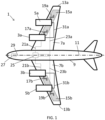
- Figure 1 illustrates a four-engine aircraft 1 according to a first embodiment.
- the aircraft 1 has a propulsion system in which four gas turbine turbofan engines 3a, 3b, 5a, 5b are mounted beneath the wings 7a, 7b of the aircraft 1.
- the engines 3a, 3b, 5a, 5b are arranged symmetrically around the centreline 11 of the aircraft 1.
- a first pair/subset 3a, 3b of the engines can be defined for which the engines are relatively closer to the aircraft fuselage 9 .
- the engines in a second pair/subset 5a, 5b are spaced further from the aircraft fuselage 9, i.e. further along the wings 7a, 7b in a span direction.
- the locations of the engines may be defined with reference to a centreline or central axis 11 of the airframe or else a spacing from a tip 13a, 13b of either wing 7a, 7b.
- Fuel tanks 15a, 15b are mounted in the wings 7a, 7b. Each engine 3a, 3b, 5a, 5b is configured to draw fuel or receive fuel from one or more fuel tank 15a, 15b via one or more fuel supply 17a, 17b, 19a, 19b. Other details of the fuel system, such as cross-feed fuel-lines, are not shown. Although the fuel-tanks are shown mounted exclusively in the wings it will be appreciated that other fuel-tank locations are also contemplated.
- Each inboard turbofan engine 3a, 3b is connected via a respective signal communication connection 21a, 21b with a control and decision-making unit 25.
- each outboard turbofan engine 5a, 5b is connected via a respective signal communication connection 23a, 23b with the control and decision-making unit 25.
- the signal communication connections 21a, 21b, 23a, 23b between the control and decision-making unit 25 and a single engine could be implemented by a single cable or bundle of cables per engine.
- the single control and decision-making unit 25 may be common to all engines 3a, 3b, 5a, 5b on the aircraft 1. In a second embodiment, some or all functions of the control and decision-making unit 25 may be incorporated into engine-specific controllers 132 (shown in Figure 2 ).
- the control and decision-making unit 25 is configured to receive signals from the cockpit 27, via signal communication connection 29, specifying for each engine 3a, 3b, 5a, 5b individually or all engines 3a, 3b, 5a, 5b concurrently a desired thrust level, or a proxy for a desired thrust level such as an angle of the one or more thrust lever in the cockpit, or a desired rotational speed of a propulsive fan of the or each engine.
- Electrical transmission connections 31a, 31b allow electrical power transfer from the inboard engines 3a, 3b to the outboard engines 5a, 5b and/or from the outboard engines 5a, 5b to the inboard engines 3a, 3b.
- the electrical transmission connections 31a, 31b could be implemented by a single cable or bundle of cables per pair of connected engines.
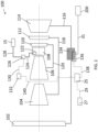
- Figure 2 shows more details of one of the gas turbine turbofan engines 100 from the aircraft 1 of Figure 1 . It will be appreciated that all four gas turbine engines in Figure 1 may be of the configuration as shown in Figure 2 .
- the gas turbine engine 100 in Figure 2 is a three-spool turbofan engine 100.
- the engine 100 comprises, in axial flow series, a propulsive fan 102, an intermediate-pressure compressor 104, a high-pressure compressor 106, a combustor 108, a high-pressure turbine 110, an intermediate-pressure turbine 112, and a low-pressure turbine 114.
- the low-pressure turbine 114 is drivingly connected via shaft 116 to the propulsive fan 102.
- the intermediate-pressure turbine 112 is drivingly connected via shaft 118 to the intermediate-pressure compressor 104.
- the high-pressure turbine 110 is drivingly connected via shaft 120 to the high-pressure compressor 106.
- the combustor 108 comprises one or more fuel injectors or fuel spray nozzles 122 which receives fuel via fuel supply pipe 124 at a rate governed by fuel pump or fuel flow regulator 126 which draws fuel from, or passes fuel received from, one or more fuel tank 15 via one or more fuel supply pipe 128 in dependence upon a fuel flow rate signal received via signal communication link 130 from an engine controller 132.
- the fan 102, low-pressure turbine 114, the shaft 116 connecting the two and any other components such as the nose cone which are obliged to rotate at the same rotational speed as the low-pressure turbine 114 are referred to as the low-pressure spool.
- the speed of rotation of the low-pressure spool is typically denoted N1.
- the intermediate-pressure compressor 104, intermediate-pressure turbine 112, the shaft 118 connecting the two, and any other components which are obliged to rotate at the same rotational speed as the intermediate-pressure turbine 112 are referred to as the intermediate-pressure spool.
- the speed of rotation of the intermediate-pressure spool is typically denoted N2.
- the high-pressure compressor 106, high-pressure turbine 110, the shaft 120 connecting the two, and any other components which are obliged to rotate at the same rotational speed as the high-pressure turbine 110 are referred to as the high-pressure spool.
- the speed of rotation of the high-pressure spool is typically denoted N3.
- the total temperature (or stagnation temperature) of air exiting the combustor 108 is typically denoted T40.
- an electrical machine 134 is attached to the low-pressure spool of the engine 100.
- the electrical machine 134 is configured to operate as a motor in a first mode of operation and as a generator in a second mode of operation. Therefore, in the first mode, the electrical machine provides assistance to the low pressure spool, increasing the speed over what could be achieved through the action of the turbine only, thus increasing the thrust output of the engine 100.
- the spool drives the electrical machine to generate electrical power, thus reducing the amount of work from the turbine that is used to provide thrust, thus reducing the thrust output of the engine 100.
- the electrical machine 134 is drivingly connected to the low-pressure shaft 116, but it is to be understood that other arrangements are contemplated in which the electrical machine 134 may be drivingly connected to other parts of the low-pressure spool.
- the electrical machine 134 may comprise a controller 136, which in turn may comprise or operate in conjunction with power electronics, such as one or more rectifier, inverter, DC-DC converter or AC-AC converter, necessary to operate the electrical machine 134 and/or to interface with other components.
- power electronics such as one or more rectifier, inverter, DC-DC converter or AC-AC converter, necessary to operate the electrical machine 134 and/or to interface with other components.
- an electrical transmission connection 31 is provided to allow power transfer from the engine 100 to one or more further engine 200, and/or from the one or more further engine 200 to the turbofan 100. This allows electrical power sharing between the low-pressure spool of the engine 100 and the low-pressure spool of the further engine, and vice versa, without the need for any electrical energy storage, such as batteries. Energy transmission along electrical transmission connection 31 will take place in only one direction at a time. The rate of energy transmission in either direction is variable.
- the engines 3a, 3b, 5a, 5b of the aircraft 1 shown in Figure 1 are divided into groups. Where the engines have different positions based on the proximity to the wingtips 13a, 13b, the groups are based on their position relative to the wingtips 13a, 13b. For example, for the aircraft 1 shown in Figure 1 , the engines are split into two groups: the inboard engines 3 and the outboard engines 5. Where all engines are positioned the same distance relative to the wingtips 13a, 13b, the engines may be split into groups based on the centreline 11 of the aircraft 1.
- the one or more further engine 200 in Figure 2 is a member of the opposite engine group to the engine 100. Therefore, in the example of Figure 1 , if the engine 100 is one of the inboard engines 3a, 3b, then the further engine 200 will be one of the outboard engines 5a, 5b and if the engine 100 is one of the outboard engines 5a, 5b, then the further engine 200 will be one of the inboard engines 3a, 3b.
- control and decision-making unit 25 receives a signal or signals representing the required thrust level (or a proxy therefor) for a plurality of engines 3, 5 from the cockpit 27 via signal communication connection 29.
- Signal communication connection 140 is provided to allow the control and decision-making unit 25 to send signals to, and optionally to receive signals from, the engine controller 132 to implement the desired thrust level.
- the electrical machine 134 and its controller 136 are also in signal communication with the control and decision-making unit 25, via signal communication connection 138.
- the signal communication connections 138, 140 may be provided by either the inboard signal communication connection 21a, 21b or outboard signal communication connection 23a, 23b discussed above.
- control and decision-making unit 25 determines the level of electrical power offtake or electrical assistance that should be taken from or applied to the low-pressure spool by the electrical machine 134 in dependence upon a variety of parameters as explained below.
- the control and decision-making unit 25 instructs the controller 136 via signal communication connection 138 to implement the determined level of electrical power offtake or electrical assistance.
- control and decision-making unit 25 determines, using well understood engine control methods that take into account the electrical assistance or power offtake, the fuel flow rate to be supplied to the fuel injector(s) or fuel spray nozzle(s) 122 to achieve the required thrust.
- the control and decision-making unit 25 instructs the engine controller 132 to implement the fuel flow rate via signal communication connection 140.
- the control and decision making unit 25 determines a change in thrust (or proxy therefor) required of the engine 100 and communicates a modified thrust demand signal to the engine controller 132 via signal communication connection 140.
- the engine controller 132 determines the required fuel flow rate using the engine control methods. In some cases, no thrust change may be required, and so the thrust signal is unmodified.
- Contrail formation can occur as engine exhaust gases mix with ambient air.
- the number density of condensation nuclei in the engine exhaust plume will influence the size distribution of ice crystals in the young contrail. Specifically, the greater the number density of condensation nuclei (contrail inducting parameter) then the smaller will be the initial size of formed ice crystals (and the greater will be the optical depth of the contrail at that point).
- the persistence of a contrail once formed is influenced by ambient conditions, and, in particular the level of ice saturation of ambient air.
- One example of the contrail inducting parameter is an initial number of non-volatile particulate matter (nvPM) emitted per unit of distance of travel of the aircraft.
- the exhaust plumes of engines 5a, 5b located sufficiently close to the wingtips 13a, 13b become at least partially entrained in the wingtip vortices of the aircraft.
- Contrail-forming particles entrained in the vortices are subject to adiabatic heating due to descent of the vortex.
- ice mass may be lost from the surface of the ice particles via sublimation, leading to elimination of some of the particles having the smallest diameter/size, thereby leading to a reduction in the optical depth of the contrail downstream of the vortex region.
- Ice particles entrained and retained within the wingtip vortices for the entire lifetime of the wingtip vortices constitute a primary wake of the aircraft and are subject to greater heating. Ice particles which remain uncaptured by wingtip vortices, and ice particles which become detrained from the wingtip vortices prior to vortex breakup, together constitute a secondary wake.
- the contribution of the outboard engines 5a, 5b to the secondary wake may be minimal depending on the precise location of the engines relative to the wingtip 13a, 13b, whereas the contribution of the inboard engines 3a, 3b to the primary wake may be minimal, or at least significantly less than that of the outboard engines 5a, 5b, particularly when the inboard engines 3a, 3b are close to the centreline 11 of the aircraft 1.
- Variation in pre-vortex ice particle size distribution can influence the particle size distribution, and hence the optical depth, of the post-vortex contrail. This is at least in part because pressure is typically lower than ambient pressure within the core of a vortex, and, as a result, the temperature is also lower. Therefore, the relative humidity within the vortex core is higher than in the ambient air, at least initially. If this relative humidity is such that the air within the vortex core is supersaturated with respect to ice, then any ice particles trapped within the core can grow as a result of a deposition process. However ice particle growth will reduce the level of super-saturation within the vortex core.
- contrail particles of smaller initial size/diameter are more likely to be completely eliminated within the wingtip vortex than larger contrail particles. This process is dependent upon the level of ambient air super-saturation, which determines the initial level of super-saturation within the wingtip vortex core and the extent of initial ice-particle growth before the adiabatic heating effects dominate. The vertical distance travelled by the vortex during its lifetime influences the degree of heating.
- any sub-saturation resulting from the adiabatic heating will result in sublimation of ice from the contrail particles in order to restore saturation. Saturation is restored once a given mass of ice has turned to vapour.
- the initially forming contrail prior to entrainment in a vortex, features a greater number density of ice particles, it will contain a greater proportion of smaller ice particles and as a result a greater proportion of ice particles will be lost during adiabatic heating within the vortex.
- the increase in optical depth, attributable to the greater initial number of ice particles, of the post-vortex contrail will be less than the increase in optical depth of the pre-vortex contrail.
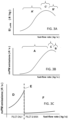
- Figure 3A shows an example chart schematically showing the dependency of the non-volatile particulate matter (nvPM) number emission index (i.e. the number of nvPM particles produced per kg of fuel burned) of an engine as a function of the fuel flow rate.
- nvPM non-volatile particulate matter
- the gradient is positive and of a magnitude which lies above a first predetermined threshold. Therefore, in the first regime, the nvPM number emission index increases with increasing fuel flow rate
- the gradient is negative and of a magnitude which lies above a second predetermined threshold. Therefore, in the second regime, the nvPM number emission index decreases with increasing fuel flow rate.
- the gradient is low in magnitude, being either positive and of a magnitude lying at or below the first predetermined threshold, or negative and of a magnitude lying at or below the second predetermined threshold.
- the nvPM# emission index increases with increasing fuel flow rate and so the percentage increase of the number density of emitted nvPM condensation nuclei caused by an increase in fuel flow rate is greater than the percentage increase of the emitted water vapour per metre of travel for the same increase in fuel flow rate.
- the nvPM# emission index decreases with increasing fuel flow rate.
- the percentage increase of the number density of emitted nvPM condensation nuclei caused by an increase in fuel flow rate is less than the percentage increase of the emitted water vapour per metre of travel for the same increase in fuel flow rate.
- the increase of the number density of emitted nvPM condensation nuclei caused by an increase in fuel flow rate may be negative i.e. representing a decrease in number density.
- the gradient of the nvPM# emission index curve is much closer to zero i.e. the curve is almost horizontal.
- the percentage increase of the number density of emitted nvPM condensation nuclei caused by an increase in fuel flow rate is broadly similar to the percentage increase of the emitted water vapour per metre of travel for the same increase in fuel flow rate.
- Examples of the calculation process for a suitable control scheme are set out below to allow a controller to identify whether there is an achievable benefit by use of the invention.
- the number of nvPM particles produced by the engine 3a, 3b, 5a, 5b per unit time is given by the product of the fuel mass flow rate of the engine and the corresponding nvPM# emission index, and is shown in Figure 3B .
- Figures 3A and 3B show respectively the nvPM# emission index and the nvPM# emission rate for a rich burn type engine, in which there is a single type of fuel injector 122.
- Figure 3C shows a corresponding relationship between fuel flow rate and nvPM particle emission-rate for a typical lean-burn combustor. This shows a first region D, to the left of staging point E, in which only pilot burners are operating in the combustor 108 , and in which nvPM# rises rapidly with increasing fuel flow rate.
- the figure also shows a second region F, to the right of staging point E, in which both the pilot burners and the main burners are operating, and in which nvPM# is much lower and rises only slowly (if at all) with increasing fuel flow rate.
- the position of staging point E is chosen such that the fuel flow rate during most or all cruise conditions falls to the right of staging point E, in a region in which the main burners are operating and in which nvPM# is very low.
- Figure 3D shows the variation in water-vapour partial pressure of a parcel of engine exhaust air with local static temperature, as it mixes with ambient air.
- Both the potential mixing trajectories start at the top right and move downwards and to the left until they reach ambient conditions shown by the arrowhead, corresponding to full dilution of the exhaust with ambient air.
- both potential mixing trajectories are the same. However, once they meet the water saturation curve their behaviours diverge. In one potential case (thick dotted line) corresponding to a complete absence of condensation, the trajectory continues down a substantially straight line. In the other potential case (thick solid line), rapid depletion by condensation of any water vapour in excess of the saturation vapour pressure corresponding to the local static temperature causes the trajectory to follow the water vapour saturation curve. In the final section, both trajectories once again follow the same path. Despite some differences in the actual path followed by each of these mixing trajectories, it will be appreciated that the overall gradient of both the mixing trajectories shown here is the same. The overall gradient of a mixing trajectory is sometimes known as the contrail factor.
- the number of possible nvPM condensation nuclei emitted per unit time is given by the product of nvPM# emission index and fuel flow rate.
- the proportion of those potential nuclei that become activated and thus give rise to ice particles is determined at least in part by the extent to which local RHW exceeds 100% during mixing.
- the contrail factor determines whether or not the mixing line reaches/crosses the water saturation curve at any point in the mixing process. If local RHW reaches/exceeds 100%, even briefly, then condensation can take place, forming water droplets. If local RHW only slightly/briefly exceeds 100%, then only a small proportion of the emitted soot particles may become activated as condensation nuclei and give rise to droplets. Conversely if local RHW greatly exceeds 100%, most or even all of the emitted soot particles may give rise to water droplets. The water droplets will then quickly freeze to yield ice particles. It will be appreciated that the two potential trajectories shown in Figure 3D represent extremes and that in practice the trajectory followed by an air parcel during mixing and condensation may often lie somewhere between these two extremes.
- Figure 3E shows the corresponding local relative humidity over water (RHW) as a function of local static temperature.
- the thick solid line rises to 100% RHW and is then capped, due to rapid condensation, at 100% RHW prior to falling to ambient RHW.
- the thick dotted line continues past 100% RHW and reaches a maximum before reducing once again.
- these two potential trajectories represent extremes and in most cases the mixing trajectory may lie somewhere between the trajectories. Therefore, in the example shown, the relative humidity experienced by an air parcel during mixing can reach a peak value of at least 100% and perhaps as high as the peak shown for the thick dotted line.
- the lower end of the mixing trajectory corresponds to, and is therefore determined by, ambient conditions. It will also be appreciated that by increasing or decreasing the overall gradient of the mixing trajectory, respectively higher or lower peak values of RHW may be reached during mixing, for the same ambient conditions.
- increasing the gradient of the overall mixing trajectory may raise the peak value of RHW such that a non-contrail forming condition may become a contrail forming condition. Conversely, reducing the gradient of the overall mixing trajectory may lower the peak value of RHW such that a contrail-forming condition may become a non-contrail-forming condition.
- the mixing trajectory and/or nvPM# emission index for each engine 3a, 3b, 5a, 5b can be selectively altered to control contrail formation.
- electrical power is transferred between the engines 3a, 3b, 5a, 5b to accommodate the changes in fuel flow rates, whilst maintaining constant total thrust for the aircraft 1.
- Figure 4 illustrates a method 300 of determining operational parameters (such as fuel flow and thrust) for the individual engines 3a, 3b, 5a, 5b or engine groups 3, 5 in the propulsion system of the aircraft 1 shown in Figure 1 .
- the control and decision making unit 25 is configured to synchronise electrical power offtake from one or more engine 3a, 3b, 5a, 5b concurrently with electrical power assistance to one or more further engine 3a, 3b, 5a, 5b to manage the formation and characteristics of contrails. Contrail formation and characteristics are controlled by changing the exhaust characteristics of the different engine groups 3, 5.
- the engines 3a, 3b, 5a, 5b each operate at substantially the same operating point, referred to herein as the nominal operating point, so as to provide a substantially equal thrust from each engine 3a, 3b, 5a, 5b.
- the fuel flow rate of each engine 3a, 3b, 5a, 5b may be substantially the same.
- different fuel flow rates are applied to each of the different engine groups 3, 5, relative to the nominal values.
- ⁇ F1 is the change in fuel flow rate required to each engine within the first group, based on the desired change in contrail characteristics.
- ⁇ T1 is the change in thrust demand to each engine in the first group, based on the desired change in contrail characteristics.
- ⁇ F1 and ⁇ T1 are determined relative to the nominal fuel flow F N and the nominal thrust T N for each engine required to maintain the desired total thrust output T to the aircraft 1, with equal thrust generated by each engine 3a, 3b, 5a, 5b and no electrical power being generated from any engine to provide assistance to any of the other engines.
- ⁇ F1 may lie within a range defined by a positive upper boundary and a negative lower boundary.
- the magnitude of the boundaries for ⁇ F1 may be a predetermined fixed value, or a predetermined percentage of the nominal fuel flow rate. Alternatively, the magnitude of a boundary for ⁇ F1 may take a different predetermined value, or a different predetermined percentage of the nominal fuel flow rate, for different nominal fuel flow rates.
- ⁇ T1 may lie within a range defined by a positive upper boundary and a negative lower boundary.
- the magnitude of the boundaries for ⁇ T1 may be a predetermined fixed value, or a predetermined percentage of the nominal thrust.
- the magnitude of a boundary for ⁇ T1 may take a different predetermined value, or a different predetermined percentage of the nominal thrust, for different nominal thrusts.
- the upper boundaries of ⁇ F1 and/or ⁇ T1 may take a different magnitude from the corresponding lower boundary.
- the boundaries of ⁇ F1 and ⁇ T1 may be selected in order to avoid compromising engine operability. The selection may be made with reference to, amongst other things, the maximum amount of electrical assistance that is available for the engines within the first engine group, the desired thrust/airspeed of the aircraft, other engine and aircraft conditions and ambient conditions. Additionally or alternatively, the boundaries of ⁇ F1 and/or ⁇ T1 may be modified, or switched to a different predetermined value or a different set of predetermined values, in response to a sensed condition, for example detection of abnormal engine operation.
- a third step 306 the mechanical assistance M1 required by each engine in the first group of engines to maintain the desired thrust level (T N + ⁇ T1) is determined, taking account of the fuel flow rate F N + ⁇ F1. This is done using methods familiar to the person skilled in the art.
- step 308 the amount of electrical assistance P1 for each engine in the first group of engines is determined, taking into account the efficiency of spool-mounted electrical machines 134 and any associated power electronics. P1 is multiplied by the total number of engines in the group to determine the total electrical assistance P1 NET required for the first group.
- the total electrical offtake required from second engine group P2 NET in order to fulfil the electrical assistance requirements of the first engine group is determined at step 310. This is divided by the number of engines in the second group to obtain the required electrical offtake P2 from each engine in the second engine group.
- the required mechanical power offtake M2 from each engine in the second group of engines is then determined at step 312.
- ⁇ T1 is set as 0 (and hence ⁇ T2 is also 0).
- the upper boundary of ⁇ F1 is less than zero.
- ⁇ F2 will always take the opposite sign to ⁇ F1. Due to imperfect efficiency of inter-engine electrical power sharing, and also due to non-linearity of thrust as a function of fuel flow rate, the magnitude of ⁇ F2 will in most cases differ from that of ⁇ F1 even when both engine groups 3, 5 have the same number of engines 3a, 3b, 5a, 5b. Where ⁇ T1 ⁇ 0, ⁇ F1 and ⁇ F2 may have the same or different sign.
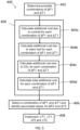
- Figure 5 illustrates an example of a method 400 of controlling the propulsion system of an aircraft 1, such as shown in Figures 1 and 2 .
- the first and second groups of engines are referred to.
- the thrust derived from combustion of fuel in the engines of the first group of engines is reduced and supplemented by electrical assistance from engines in the second group.
- either the inboard engines 3a, 3b or outboard engines 5a, 5b can be the first group of engines and the other of the inboard engines 3a, 3b or outboard engines 5a, 5b can be the second group.
- the possible combinations of ⁇ F1 and ⁇ T1 are determined for both the inboard engines 3a, 3b being defined as the first group and the outboard engines 5a, 5b being defined as the first group.
- the ⁇ F1 and ⁇ T1 take a number of possible discrete values between the upper and lower boundaries discussed above.
- the available range for ⁇ F1 and ⁇ T1 may be divided into a fixed number of discrete values. Therefore, where the upper and lower boundaries are relatively close, the step change between consecutive values may be relatively small compared to when the upper and lower boundaries are relatively far apart. Alternatively, there may be a fixed step between values, no matter what the boundaries. In this cases, wide ranges will cover a larger search space than narrower ranges. In yet further examples, the spacing between the different values may be different across the available range.
- a second step 404 fuel-use, carbon dioxide emissions and contrail properties are calculated for each possible combination of ⁇ F1 and ⁇ T1, to identify the resulting costs per unit distance of flight for each combination.
- the cost per unit distance of flight for ⁇ F1 and ⁇ T1 0 (the nominal operating condition) is also calculated.
- a summation over engines or over engine groups is then performed to yield a total cost per unit distance of flight for the aircraft for each proposed combination of ⁇ F1 and ⁇ T1.
- step 406 a combination of ⁇ F1 and ⁇ T1 (and the associated ⁇ F2 and ⁇ T2) is selected for use. This may be the combination of ⁇ F1 and ⁇ T1 that gives the most negative change in total cost per unit distance of flight of the aircraft.
- step 408 the determined ⁇ F1, ⁇ T1, ⁇ F2 and ⁇ T2 and the required electrical assistance and electrical offtake are implemented by the control and decision-making unit 25.
- ⁇ F2 and ⁇ T2 are calculated for each combination of ⁇ F1 and ⁇ T1 using the method shown in Figure 4 .
- the method set out in EP 3 875 742 is used.
- the post-vortex contrail properties are converted into an engine-specific or engine group-specific contrail climate impact per unit distance of flight using methods known to the skilled person, taking account of current ambient conditions and also predicted ambient conditions over the expected lifetime of the contrail, including not only atmospheric conditions but also the albedo of the underlying surface or cloud partly shielded from sunlight by the contrail.
- the lifetime climate impact will take account of cooling aspects of the contrail as well as warming aspects.
- the engine-specific or engine group-specific contrail climate impact is converted into an engine-specific or engine group-specific cost per unit distance of flight using a metric or exchange rate which assigns a financial value to the contrail climate impact. This may be based on calculating the contrail climate impact directly using methods known to the skilled person, and its value would be greater (corresponding to a higher cost) for a contrail which is more warming (or less cooling) and lower (corresponding to a lower cost) for a contrail which is less warming (or more cooling).
- the engine-specific or engine group-specific additional climate impact of carbon dioxide related to the additional fuel burn is calculated and converted into an additional carbon dioxide cost using a suitable metric or exchange rate which assigns a financial value to the climate impact. This may take into account, for example, costs levied per tonne of carbon dioxide generated, the cost of offsetting carbon dioxide emissions and/or other factors. This could also be negative for some engines 3a, 3b, 5a, 5b or engine groups 3, 5.
- the engine-specific or engine group-specific overall additional cost (relative to nominal operation) per unit distance of flight is the sum of the engine-specific or engine group-specific additional contrail cost, carbon dioxide cost and fuel cost.
- the summation may be weighted to increase or decrease the relative significance of one or more individual sources of cost relative to an equal weighting summation.
- the sum of the engine-specific or engine group-specific overall additional cost per unit distance of flight over all engines or engine groups on the aircraft is determined in step 404d to give a total additional cost per unit distance of flight for the entire aircraft 1.
- first-engine-group-choice ⁇ F1 and ⁇ T1
- the additional contrail cost at the aircraft level will be negative to an extent that it exceeds the aircraft-level positive additional carbon dioxide cost and the aircraft-level positive additional fuel cost, leading to a negative value for the overall additional cost per unit distance of flight. This would therefore provide an overall benefit in cost (or contrail formation) for the whole aircraft 1.
- control and decision making unit 25 sends the following instructions:
- the engine controller 132 determines the necessary fuel flow to achieve and/or maintain the requested thrust level (or proxy therefor), taking account of the effect of the implemented electrical power offtake or electrical assistance, using conventional engine control methods. Alternatively, this may be determined at the control and decision-making unit 25 and sent to the engine controllers 132.
- Delays may be caused principally by the time taken for the rotational speeds of the spools of an engine 3a, 3b, 5a, 5b, 100, 200 to respond to a change in fuel flow rate and/or to a change in the torque or power of an electric motor/generator 134. Delays may be different for different spools of the engine and may be different for fuel flow rate adjustments than for adjustments in electrical power offtake / electrical assistance.
- a trajectory is defined for each parameter from its preadjustment value to its post-adjustment value.
- the trajectory for each parameter may include intermediate waypoints, the number of waypoints being the same for all parameters undergoing adjustment.
- the waypoints are defined to ensure that the overall thrust provided to the aircraft remains constant throughout the transition.
- the adjustment for each parameter may be conducted in steps, each step corresponding to the transition from one waypoint to the next waypoint on the trajectory for that parameter. The next step may only be performed if all other parameters have reached the current waypoint and are ready to make the step to the next waypoint. Using this method prevents changes attributable to adjustments in one parameter from getting substantially ahead or behind changes attributable to adjustments in one or more further parameter and avoids or reduces momentary changes in the thrust delivered to the aircraft.
- An alternative approach is to set a predetermined rate limit for each parameter which would prevent adjustments for that parameter from proceeding at a rate exceeding the rate limit.
- the predetermined rate limit for each parameter would be set so that adjustments for all parameters proceed at a rate corresponding to that of the slowest-responding parameter.
- the method 400 may be repeated throughout a flight mission or part of a flight mission. In one example, the method 400 may be repeated continuously, such that it restarts at step 402 as soon as it is completed at step 408.
- the method may be repeated after the parameters determined from the previous iterations have been implemented.
- the repetition of the method may be time based, at regular interval (for example every minute, every ten seconds, every second).
- the calculation may be repeated in response to a sensed material change in conditions (requested thrust level, ambient temperature, ambient humidity, ambient pressure, forecasted future ambient conditions, time of day).
- the method 400 shown in Figure 5 may include the initial step of determining which engine group is the first engine group. This may be based on heuristic learning, look up tables or other suitable models. This reduces the number of combinations of ⁇ F1 and ⁇ T1 that are searched in the method 400 of Figure 5 .
- the method 400 may employ various search strategies in order to identify a combination of ⁇ F1 and ⁇ T1 to use. For example, a first search may be carried out across the full possible ranges of ⁇ F1 and ⁇ T1, with a first spacing between values of ⁇ F1 and ⁇ T1. Then a second search, with smaller spacing between ⁇ F1 and ⁇ T1 may be carried out in a sub-range identified by the first search.
- ⁇ F1 and ⁇ T1 may be continuously variable between the upper and lower boundaries and various search strategies may be employed to search over the parameter space to find either a global optimal result or a local optimal result that is acceptable for use.
- FIG. 2 The engine configuration shown in Figure 2 is given by way of example only.
- Figures 6 and 7 show alternative examples of engines 100a, 100b that may be used in the propulsion system discussed above. Where the engines 100a, 100b of Figures 6 and 7 include the same features as the three-spool engine 100 of Figure 2 , the same reference numbers are used.
- FIG. 6 shows an example of a two-spool engine 100a.
- the two-spool engine 100a includes, in axial flow series, a propulsive fan 102, a booster compressor 142, a high-pressure compressor 106, a combustor 108, a high-pressure turbine 110, and a low-pressure turbine 114.
- the low-pressure turbine 114 is drivingly connected via shaft 116 to the propulsive fan 102 and the booster compressor 142.
- the high-pressure turbine 110 is drivingly connected via shaft 120 to the high-pressure compressor 106.
- the combustor 108 comprises one or more fuel injectors or fuel spray nozzles 122 which receives fuel via fuel supply pipe 124 at a rate governed by fuel pump or fuel flow regulator 126 which draws fuel from, or passes fuel received from, one or more fuel tank 15 via one or more fuel supply pipe 128 in dependence upon a fuel flow rate signal received via signal communication link 130 from an engine controller 132.
- the fan 102, the booster compressor 142, the low-pressure turbine 114, the shaft 116 connecting these components, and any other components such as the nose cone which are obliged to rotate at the same rotational speed as the low-pressure turbine 114 are referred to as the low-pressure spool.
- the speed of rotation of the low-pressure spool is typically denoted N1.
- the high-pressure compressor 106, high-pressure turbine 110, the shaft 120 connecting the two, and any other components which are obliged to rotate at the same rotational speed as the high-pressure turbine 110 are referred to as the high-pressure spool.
- the speed of rotation of the high-pressure spool is typically denoted N3.
- Figure 7 illustrates a geared engine 100b.
- the geared engine 100b includes, in axial flow series, a propulsive fan 102, a power gearbox 144, an intermediate-pressure compressor 104, a high-pressure compressor 106, a combustor 108, a high-pressure turbine 110, and an intermediate-pressure turbine 112.
- the intermediate-pressure turbine 112 is drivingly connected via shaft 118 to the intermediate-pressure compressor 104.
- the high-pressure turbine 110 is drivingly connected via shaft 120 to the high-pressure compressor 106.
- the intermediate-pressure compressor 104 drives the power-gearbox 144 either directly or via an optional shaft 146, while the power-gearbox 144 drives the propulsive fan 102 either directly or via an optional shaft 148.
- the combustor 108 comprises one or more fuel injectors or fuel spray nozzles 122 which receives fuel via fuel supply pipe 124 at a rate governed by fuel pump or fuel flow regulator 126 which draws fuel from, or passes fuel received from, one or more fuel tank 15 via one or more fuel supply pipe 128 in dependence upon a fuel flow rate signal received via signal communication link 130 from an engine controller 132.
- the fan 102, optional shaft 148, part of the power gearbox 144, and any other components such as the nose cone which are obliged to rotate at the same rotational speed as the fan 102 are referred to as the low-pressure spool.
- the speed of rotation of the low-pressure spool is typically denoted N1.
- the intermediate-pressure spool Collectively, a further part of the power gearbox 144, the optional shaft 146, the intermediate-pressure compressor 104, intermediate-pressure turbine 112, the shaft 118 connecting the two, and any other components which are obliged to rotate at the same rotational speed as the intermediate-pressure turbine 112 are referred to as the intermediate-pressure spool.
- the speed of rotation of the intermediate-pressure spool is typically denoted N2.
- the high-pressure compressor 106, high-pressure turbine 110, the shaft 120 connecting the two, and any other components which are obliged to rotate at the same rotational speed as the high-pressure turbine 110 are referred to as the high-pressure spool.
- the speed of rotation of the high-pressure spool is typically denoted N3.
- the total temperature (or stagnation temperature) of air exiting the combustor 108 is typically denoted T40 for the engines 100a, 100b shown in both Figures 6 and 7 .
- an electrical machine 134 is attached to the low-pressure spool of the engine 100a, shown in Figure 6 .
- This electrical machine 134 can provide electrical assistance to the low-pressure spool or act as a generator driven by the low-pressure spool.
- an electrical transmission connection 31 is provided to allow power transfer from the engine 100a of Figure 6 to one or more further engine 200a, and/or from the one or more further engine 200a to the engine 100a, to allow electrical power sharing between the low-pressure spool of the engine 100a and the low-pressure spool of the further engine 200a, and vice versa.
- an electrical machine 134 is attached to the intermediate pressure spool.
- This electrical machine 134 can provide electrical assistance to the intermediate-pressure spool or act as a generator driven by the intermediate-pressure spool.
- an electrical transmission connection 31 is provided to allow power transfer from the engine 100b of Figure 7 to one or more further engine 200b, and/or from the one or more further engine 200b to the engine 100b, to allow electrical power sharing between the intermediate-pressure spool of the engine 100b and the intermediate-pressure spool of the further engine 200b, and vice versa.
- the one or more further engine 200a, 200b is a member of the opposite engine group to the engine 100a, 100b. Therefore, if the engine 100a, 100b is one of the inboard engines 3a, 3b, then the further engine 200a, 200b will be one of the outboard engines 5a, 5b and if the engine 100a, 200a is one of the outboard engines 5a, 5b, then the further engine 200a, 200b will be one of the inboard engines 3a, 3b.
- control and decision-making unit 25 receives a signal or signals representing the required thrust level (or a proxy therefor) of a plurality of engines 3, 5 from the cockpit 27 via signal communication connection 29.
- Signal communication connection 140 is provided to allow the control and decision-making unit 25 to send signals to, and optionally to receive signals from, the engine controller 132 as described above in relation to the three spool engine 100.
- the electrical machine 134 and its controller 136 are also in signal communication with the control and decision-making unit 25, via signal communication connection 138.
- the signal communication connections 138, 140 may be provided by either the inboard signal communication connection or outboard signal communication connection discussed above.
- the engines 100a, 100b shown in Figures 6 and 7 may be used on the aircraft 1 shown in Figure 1 .
- the methods discussed in relation to Figures 4 and 5 may be applied using the engines 100a, 100b in Figures 6 or 7 in place of the three spool engine 100, without any modification to the method or aircraft 1.
- the electrical machine 134 drives or is driven by the low-pressure spool. This is by way of example only. In other examples, the electrical machine may drive or be driven by any other spool of the engine 100, 100a, 100b.
- Figure 7 illustrates the electrical machine 134 driving or being driven by the intermediate-pressure spool. In yet further examples, there may be electrical machines 134a, 134b in multiple spools of the engine 100, 100a, 100b.
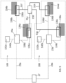
- Figures 8 and 9 illustrate examples of engine systems having electrical machines 134a, 134b on two spools of the engine.
- Figures 8 and 9 show only the electrical connections and signal communication connections.
- the engines 100, 200 are ungeared and thus comprise a low-pressure spool and a high-pressure spool.
- the systems in Figures 8 and 9 may be used in any of the above engine configurations.
- a first electrical machine 134a, 134c is provided on the low-pressure spool of each engine 100, 200, and a second electrical machine 134b, 134d is provided on the high-pressure spool.
- Each electrical machine is provided with a corresponding controller 136a, 136b, 136c, 136d in a similar manner to the system discussed with respect to Figure 2 .
- the first electrical machines 134a, 134c communicate with the respective control and decision making units 25a, 25b by respective signal communication connections 138a, 138c and the second electrical machines 134b, 134d communicate with the respective control and decision making units 25a, 25b by respective signal communication connections 138b, 138d.
- the control and decision making units 25a, 25b communicate with the respective engine controllers 132a, 132b by signal communication connections 140a, 140b and with the cockpit 27 through signal communication connections 29a, 29b.
- control and decision making units 25a, 25b could be physically co-located or even combined into a single control and decision making unit 25, which communicates with the cockpit 27 through a single signal communication connection 29, as shown in Figure 1 .
- a first electrical transmission connection 31c connects the electrical machine 134a on the low-pressure spool of the first engine 100 to the electrical machine 134c on the low-pressure spool of the second engine 200.
- a second electrical transmission connection 31d connects the electrical machine 134b on the high-pressure spool of the first engine 100 to the electrical machine 134d on the high-pressure spool of the second engine 200.
- the arrangement in Figure 8 allows the low-pressure spool of the first engine 100 to receive electrical assistance from the low-pressure spool of the second engine 200, or provide electrical assistance to the low-pressure spool of the second engine, and allows the high-pressure spool of the first engine 100 to receive electrical assistance from the high-pressure spool of the second engine 200, or provide electrical assistance to the high-pressure spool of the second engine.
- a power sharing interface 150 is provided between the first engine 100 and the second engine 200.
- the electrical machine 134a on the low-pressure spool of the first engine 100 is connected to the power sharing interface 150 by a first electrical transmission connection 31e
- the electrical machine 134b on the high-pressure spool of the first engine 100 is connected to the power interface 150 by a second electrical transmission connection 31f
- the electrical machine 134c on the low-pressure spool of the second engine 200 is connected to the power sharing interface 150 by a third electrical transmission connection 31g
- the electrical machine 134d on the high-pressure spool of the second engine 200 is connected to the power sharing interface 150 by a fourth electrical transmission connection 31h.
- the power sharing interface 150 is configured such that electrical power offtake from any spool of the first engine 100 with a corresponding electrical machine 134a, 134b need not be used to provide electrical assistance solely to the corresponding spool of the further engine 200 but could instead be used to provide electrical assistance to either or both of the spools with electrical machines 134c, 134d.
- the interface 150 is further configured such that electrical assistance to any spool of the first engine 100 need not be sourced solely from the corresponding spool of the second engine 200, but could instead be sourced from either or both of the spools with electrical machines 134c, 134d of the second engine 200.
- each engine includes electrical machines 134, there are a number of factors which are considered when controlling the operation of the propulsion system.
- contrail enhancement rather than contrail reduction, is deemed advantageous, then, for a fixed engine thrust level, taking electrical offtake from the low-pressure spool reduces the bypass mass flow and thus exerts a greater impact upon contrail factor than power offtake from the high-pressure spool.
- Electrical assistance to the low-pressure spool is likely to result in a greater amount of additional thrust per MW of assistance compared to electrical assistance to the high-pressure spool and hence enables a greater reduction in fuel flow rate to return to a nominal thrust setting, due to the higher propulsive efficiency of bypass exhaust relative to core exhaust.
- the per-engine high-pressure spool power offtake in the second engine group is set to a maximum value, the maximum value being determined with reference to the torque and/or power ratings of the electrical machine 134b, 134d, the power ratings of the power electronics, and any constraints imposed by operability requirements for engines of the second engine group.
- the per-engine electrical power offtake from the high-pressure spool of engines in the second engine group will be greater than or equal to the per-engine electrical offtake required from the second engine group to fulfil the electrical assistance requirement of the high-pressure spools of the engines in the first engine group, which may be zero.
- the per-engine low-pressure spool power offtake from engines in the second engine group will be correspondingly less than or equal to the per-engine electrical offtake required from the second engine group to fulfil the electrical assistance requirement of the low-pressure spools of the engines in the first engine group.
- the ability to provide electrical assistance to the high-pressure spool of engines in the first engine group, as shown in the systems of Figure 8 and 9 , may for some engine architectures mean that the lower boundary of ⁇ F1 could be more negative (corresponding to a greater reduction in fuel flow rate) without compromising surge margin of the low and/or intermediate-pressure compressors and/or booster compressor, thus enabling a wider envelope of operation.
- Figures 10 to 13 give further examples of aircraft 1a, 1b, 1c, 1d that may operate using the engines 100, 100a, 100b discussed above, and according to the methods 300, 400 set out in Figures 4 and 5 .
- the aircraft of Figures 10 to 13 include the same features as the four engine aircraft 1 of Figure 1 , the same reference numbers are used.
- FIG 10 shows a three-engine aircraft 1a, with otherwise substantially the same components as the aircraft 1 in Figure 1 .
- the aircraft comprises an engine 5a, 5b mounted under each wing 7a, 7b, and a fuselage mounted engine 3.
- the wing mounted engines 5a, 5b may be mounted at any suitable position along the wings 7a, 7b.
- the fuselage mounted engine 3 is shown drawing fuel from a dedicated fuel tank 15c in the tail of the aircraft 1a through fuel pipe 17.
- a dedicated fuel tank 15c in the tail of the aircraft 1a through fuel pipe 17.
- other arrangements are contemplated.
- the fuselage mounted engine 3 is considered the inboard engine, while the wing-mounted engines 5a, 5b are considered the outboard engines even though they may be mounted at positions similar to the inboard engines of aircraft 1.
- the single inboard engine 3 is in communication with the control and decision making unit 25 through signal communication connection 21. Both outboard engines 5a, 5b share power with the single inboard engine through respective electrical transmission connections 31a, 31b.
- Figure 11 shows a second example of an aircraft 1b with three engines.
- the aircraft 1b in Figure 11 is a blended wing configuration. As such there is no distinct fuselage, wing or tail.
- An inboard engine 3 is mounted at the centreline 11 of the aircraft 1b, in-between two outboard engines 5a, 5b.
- the first outboard engine 5a draws fuel from a first fuel tank 15a through fuel pipe 19a
- the second outboard engine 5b draws fuel from a second fuel tank 15b through fuel pipe 19b.
- the inboard engine 3 is shown drawing fuel through fuel pipes 17a, 17b from either or both of the main outboard tanks 15a, 15b, although it is to be understood that other fuel-system arrangements are contemplated, including an arrangement where the inboard engine draws fuel from a dedicated tank or tanks.
- the single inboard engine 3 is in communication with the control and decision making unit 25 through signal communication connection 21. Both outboard engines 5a, 5b share power with the single inboard engine through respective electrical transmission connections 31a, 31b.
- Each of the aircraft 1a, 1b shown in Figures 10 and 11 may make use of any of the engines and methods discussed above.
- Figure 12 shows an aircraft 1c with only two engines 5a, 5b mounted under the wings 7a, 7b. This configuration is similar to the one shown in Figure 10 , without the fuselage mounted engine 3. In this example, there is a single power sharing connection 31 between the two engines 5a, 5b.
- FIG 13 shows a further example of an aircraft 1d with only two engines 5a, 5b. This is the same as the aircraft in Figure 12 , except the engines 5a, 5b are mounted on pylons attached to the fuselage 9 at the rear of the aircraft 1d.
- inboard and outboard engines there is no distinction between inboard and outboard engines.
- either engine may be assigned to the first engine group, with the other engine being assigned to the second engine group.
- the assignment of the groups is arbitrary, and so there is no need to perform any analysis of the combinations of ⁇ F1 and ⁇ T1 for setting both engines 5a, 5b as the first group. Instead, it is only necessary to perform the analysis with one of the engines 5a, 5b as the first group.
- any of the engines and methods discussed above may be used.
- the ambient relative humidity over ice (RHI) is less than 100%.
- the aircraft 1 has a configuration as shown in Figure 1
- the combustor 108 is of a rich burn type having nvPM# emissions as shown in Figures 3A and 3B , and operating in region A of Figures 3A and 3B .
- ambient RHI is modestly over 100% (for example between 100% and 110%) and the maximum potential RHW when the exhaust mixes with ambient air is over 100% when operating all engines at their nominal operating points. It is assumed that ambient and operational conditions are such that contrail reduction (or elimination) is favoured.
- inboard engines 3a, 3b would be assigned to the first engine group, and outboard engines 5a, 5b to the second engine group.
- Reduction of fuel flow rate of the inboard engines 3a, 3b, coupled with electrical assistance to the low-pressure spools of the engines will have the effect of reducing the proportion of emitted nvPM particles that become activated as condensation nuclei (except in very cold ambient conditions). In some cases this may limit the maximum value of RHW during the mixing of inboard engine exhaust with ambient air to values less than 100%, and thus may be sufficient to prevent inboard engine contrail formation altogether. Also on the inboard engines 3a, 3b, reduction of fuel flow rate reduces nvPM particle emissions per unit distance of travel, leading to a reduction in the number of potential condensation nuclei.
- an increase of fuel flow rate coupled with electrical power offtake from the low-pressure spools may increase the proportion of emitted nvPM particles that become activated as condensation nuclei (unless said proportion is already 100% or close to 100%).
- the outboard engine nvPM particle emission rate may remain in region A of Figures 3A and 3B , or may be move into region B, where the nvPM particle emissions rate may in some cases be reduced relative to the nominal value.
- a reduction of fuel flow rate causes the nvPM# to rise substantially due to a migration into the pilot-only regime of region D to the left of the staging point E in Figure 3C .
- the proportion of emitted nvPM particles that become activated as condensation nuclei may be reduced.
- the net effect is to increase the number of ice particles formed.
- contrails formed by both engines are enhanced due to an increase in the number of formed ice particles in their respective exhaust plumes.
- Example 4 is the same as example 3, except the aircraft configuration 1c shown in Figure 12 is used, and the ambient RHI is at least 130%. Since the engines 5a, 5b are mounted further from the fuselage their exhausts are likely to interact more strongly with the wingtip vortices. In this example the same actions are taken as for example 3. The benefits could be larger however due to the contrail spreading effect of the wingtip vortex interaction, since due to the high ambient RHI, a high proportion of formed ice particles may survive the wingtip vortex interaction.
- the aircraft 1a, 1b has the configuration shown in Figures 10 or 11 (in which the inboard engine 3 is situated along the aircraft centreline 11).
- the combustor is of a rich-burn type as discussed with reference to Figures 3A and 3B , operating in region A.
- the ambient RHI is modestly above 100%, and the maximum potential RHW in the exhaust plume when operating all engines at their nominal operating points is also modestly above 100%. Conditions are such that contrail reduction or elimination is desired.
- the one inboard engine 3 is assigned to the first engine group while the two outboard engines 5a, 5b are assigned to the second engine group.
- This approach is motivated by the observation that (given the assumed modest level of ambient RHI) wingtip vortex processing may mitigate increases in outboard engine exhaust ice particle numbers to a greater extent than it may dilute reductions in inboard engine exhaust ice particle numbers.
- the extent of reduction in the overall gradient of the mixing trajectory that can be achieved on that engine is (subject to inboard engine operability limits) substantially greater than could be achieved on the two outboard engines if the opposite engine-group assignment were to be made, and so there is a greater likelihood of achieving complete suppression of the inboard engine contrail without exceeding T40 limits on the second engine group.
- the two outboard engines 5a, 5b are assigned to the first engine group, and the one inboard engine 3 is assigned to the second engine group
- nvPM# emissions due to reduced fuel flow rate
- a reduction in the proportion of those emissions which become activated due to reduced fuel flow rate in conjunction with electrical assistance to the low pressure spool
- the aircraft 1a, 1b has the configuration shown in Figures 10 or 11 (in which the inboard engine 3 is situated along the aircraft centreline 11).
- the combustor is of a rich-burn type as discussed with reference to Figures 3A and 3B , operating in region A.
- the ambient RHI is substantially above 100%, and the maximum potential RHW in the exhaust plume when operating all engines at their nominal operating points is below 100%. Conditions are such that contrail enhancement is desired.
- This example illustrates a case in which a non-contrail formation condition may be turned into a contrail formation condition for at least one engine, and in which the wingtip vortex interaction results in a spreading/enhancement of outboard engine contrails (if formed).
- the inboard engine 3 may be assigned to the first group or the second group. Examples 6a and 6b discuss both options, in turn.
- the inboard engine 3 is assigned to the first engine group and the outboard engines 5a, 5b to the second engine group. This causes an increase in the maximum RHW that can be reached in the outboard engine 5a, 5b exhaust plumes during mixing with ambient air. If the system is capable of sufficiently large adjustments in fuel flow rate and inter-engine electrical power transfer (which are limited by the fact that there is only one inboard engine 3), the outboard engines 5a, 5b may be moved to a contrail forming condition, and furthermore in the chosen ambient conditions the wingtip vortex interaction will further enhance the resulting contrail due to spreading.
- Example 6b may be useful when it is not possible to make sufficiently large changes in order to move both outboard engines 5a, 5b to a contrail forming condition, and it may instead be possible to move the single inboard engine to a contrail forming condition. Although this would only move one engine, rather than two engines, to a contrail forming condition, and although the formed contrail may benefit less from the spreading effect of wingtip vortex interaction, nonetheless in the context of an example in which contrail enhancement is deemed advantageous, one contrail is preferable to no contrail.
- the outboard engines 5a, 5b are assigned to the first engine group and the inboard engine 3 to the second engine group.
- the aircraft 1a, 1b has the configuration shown in Figures 10 or 11 (in which the inboard engine 3 is situated along the aircraft centreline 11).
- the combustor is of a rich-burn type as discussed with reference to Figures 3A and 3B , operating in region A.
- the ambient RHI is marginally above 100%, and the maximum potential RHW in the exhaust plume when operating all engines at their nominal operating points is below 100%. Conditions are such that contrail enhancement is desired.
- This example illustrates a case in which a non-contrail formation condition can be turned into a contrail formation condition for at least one engine, and in which the wingtip vortex interaction results in partial elimination of outboard engine contrails.
- the outboard engines are chosen as the first engine group (fuel flow rate reduction, electrical assistance to the low-pressure shaft) and would thus be moved further into a non-contrail-forming condition.
- the inboard engine 3 is assigned to the second engine group (fuel flow rate increase, electrical power offtake from the low-pressure spool), raising the overall gradient of the mixing trajectory in order to increase the maximum RHW achieved during mixing to a value above 100%, enabling contrail formation. Note that the achievable change on the single inboard engine 3 is greater than the change on the two outboard engines, due to the requirement for overall thrust to remain unchanged.
- aircraft 1, 1a, 1b, 1c, 1d having two, three or four engines are discussed.
- Aircraft configurations having more than four engines 3a, 3b, 5a, 5b may also be contemplated.
- the method may still only consider two groups of engines (no matter the total number of engines): inboard engines and outboard engines.
- each group may comprise more than two engines (or more than one engine on each wing).
- each specific inboard engine may be connected to one specific outboard engine.
- a separate control and decision making unit 25 may be provided for the first and second repeated systems.
- a single control and decision making unit 25 may be used.
- engines may be combined to form virtual engines, such that the method still effectively operates on a four engine system (one engine per group per wing).
- more than two separate groups may be defined in the method.
- the available range within which the thrust distribution between engine groups may be altered could be substantially smaller than for aircraft configurations which maintain thrust symmetry.
- the boundaries for ⁇ T1 may be selected to avoid exceeding a maximum acceptable level of thrust asymmetry.
- the additional fuel-burn necessary to overcome rudder drag arising from correction of any thrust asymmetry may be incorporated in the costs discussed above.
- the maximum acceptable level of thrust asymmetry may be substantially zero.
- the electrical assistance/offtake is evenly distributed within the engine group, but this need not be the case.
- thrust asymmetry may also allow the above methods to be used where not all engines are operational.
- a reduction in fuel flow rate to an engine is accompanied by a corresponding increase in electrical assistance
- an increase in the fuel flow rate is accompanied by an increase in electrical off-take.
- electrical assistance may be provided from one engine group to another without any changes in the fuel flow rates. This will provide additional thrust at the engine group receiving the assistance and reduce thrust at the engine group providing the assistance.
- each electrically enabled spool may have any number of electrical machines mounted on it in any suitable arrangement. Electrical machines may be mounted on any spool of the engine 3, 3a, 3b, 5a, 5b.
- all engines 3, 3a, 3b, 5a, 5b on an aircraft are of the same type and configuration.
- engines within the same group may be same configuration but engines within different groups may be of different configurations.
- engines within the same group may have different configurations.
Landscapes
- Engineering & Computer Science (AREA)
- Aviation & Aerospace Engineering (AREA)
- Chemical & Material Sciences (AREA)
- Combustion & Propulsion (AREA)
- Mechanical Engineering (AREA)
- General Engineering & Computer Science (AREA)
- Engine Equipment That Uses Special Cycles (AREA)
Abstract
Description
- This disclosure relates to an aircraft propulsion system and to a method for operating a propulsion system. In particular, but not exclusively, the present invention relates to an aircraft propulsion system in which electrical energy is used to supplement the operation of a combustion engine.
- Contrails, also known as condensation trails or vapour trails, are line-shaped ice-clouds that appear behind aircraft under certain circumstances. The formation of a contrail depends on a number of factors, including: ambient temperature, humidity and pressure; the efficiency of the engines; and the properties of the fuel burned in the engines.
- A contrail, once formed, will typically dissipate within a minute or so, unless the ambient air is supersaturated with respect to ice (i.e. having a relative humidity over ice (RHI) of more than 100%), in which case the contrail may persist. A persistent contrail will grow over time to resemble natural cirrus cloud, both in size and optical properties, and is referred to as "contrail-cirrus". Line-shaped contrails and contrail-cirrus are collectively referred to as "aviation-induced cloudiness" (AIC). Contrail-cirrus is thought to cause a majority of the climate impact of aviation induced cloudiness due to it being spatially-larger and longer-lived than non-persistent line-shaped contrails.
- Depending on the metric employed, the climate-warming impact of aviation-induced cloudiness may be of a similar magnitude to that of the carbon dioxide emitted by aircraft, and may therefore represent a significant element of the total climate impact from aviation. The control of contrail formation and/or contrail properties, and particularly the reduction of the impact of persistent contrails, therefore, represents a compelling opportunity for a significant reduction in the overall climate warming impact of aviation.
- Conventional propulsion systems for civil aircraft typically comprise one or more turbofan gas turbine engine placed under the wing of the aircraft or mounted on the fuselage.
- Exhaust plumes of engines located sufficiently close to the wingtips of an aircraft will become at least partially entrained in the wingtip vortices of the aircraft. Contrail ice particles entrained in the vortices are subject to adiabatic heating due to descent of the vortex. As a result, ice mass can be lost from the surface of the entrained ice particles via sublimation, leading to elimination of some of the particles, thereby leading to a reduction in the optical depth of the contrail downstream of the vortex region. This effect is particularly evident on relatively large/heavy aircraft for which the wingtip vortices are strong in nature. This effect is less evident when ambient air is highly supersaturated with respect to ice.
- In comparison with contrails produced by outboard engines, contrails produced by inboard engines interact less strongly with wingtip vortices, and contrails produced by engines mounted very close to the centreline of the aircraft interact much less strongly with the wingtip vortex cores. Hence there is a distinction between outboard and inboard engines, as far as interaction with wingtip vortices is concerned, particularly where the inboard engines are very close to the centreline of the aircraft. Exhaust plumes of outboard engines of a four-engine aircraft are more quickly and more effectively entrained into the trailing vortex than those of the inboard engines, or those of conventional two-engined aircraft.
- Ice particles which survive the wingtip-vortex make up a contrail whose vertical extent is greatly increased, perhaps to several hundred metres, as a result of wingtip-vortex interaction. In the presence of ambient wind-shear, a vertically-large contrail can also spread laterally so as to cover a much larger amount of sky. Therefore, in some cases, the product of the contrail's optical depth and its width can be increased by the wingtip vortex interaction, while in others, it can be decreased by the wingtip vortex interaction due to the elimination of ice particles having a greater effect than spatial spreading. Therefore, depending on a number of conditions, entraining of the exhaust plume in the wingtip vortex may increase or reduce aviation induced cloudiness.
- It is an object of the present disclosure to manage the formation of contrails by aircraft engines in a manner that reduces negative impact on the climate.
- According to a first aspect there is provided an aircraft propulsion system comprising: at least two engines, each engine having: a propulsive fan and an engine core, the engine core comprising a compressor, a combustor and a turbine driven by a flow of combustion products from the combustor, the propulsive fan configured to generate a mass flow of air that bypasses the engine core to generate thrust; a first electrical machine coupled to a first engine, the first electrical machine arranged to be driven by electrical power in order to at least partially drive the first engine; a second electrical machine coupled to a second engine, the second electrical machine arranged to be driven by the second engine to generate electrical power; an electrical network arranged to allow transmission of electrical power between the first electrical machine and the second electrical machine; and a controller arranged to, based on expected properties of contrails formed in an exhaust plume of the first engine and/or second engine, selectively reduce fuel flow to the first engine, and provide electrical power from the second electrical machine to the first electrical machine, to drive the first electrical machine.
- The controller may be arranged to selectively change fuel flow to the second engine concurrently with reducing the fuel flow to the first engine.
- The amount of electrical power provided to the first electrical machine and the change in fuel flow to the second engine may be arranged to maintain the total thrust of the aircraft as unchanged.
- The controller may be arranged to change the fuel flow to the second engine such that the thrust of the second engine remains unchanged, and wherein the electrical power provided to the first electrical machine causes the thrust of the first engine to remain unchanged.
- The change in fuel flow to the second engine may be of the opposite sign to the change in fuel flow to the first engine. The change in fuel flow to the second engine may also be of a different magnitude to the change in fuel flow to the first engine.
- The thrust of the first and second engines may be changed when the electrical power transfer occurs.
- The first and second engines may be provided at different distances from a centreline of the aircraft, such that an exhaust plume of one of the engines is entrained in a wingtip vortex, to a greater degree than an exhaust plume of the other engine.
- The aircraft propulsion system may comprise: three or more engines each having a corresponding electrical machine coupled to the engine. The engines may be arranged in groups, each group having one or more engine. The controller may be arranged to, based on expected properties of contrails formed in exhaust plumes of engines in a first group of engines and/or engines in a second group of engines, selectively reduce fuel flow to the engines in the first group of engines, and provide electrical power from the electrical machines coupled to the engines in the second group of engines to the electrical machines coupled to the engines in the first group of engines, to drive the electrical machines coupled to the engines in the first group of engines to at least partially drive the engines in the first group of engines.
- Each engine may comprise one or more spools. The electrical machines may be coupled to the same spool of each engine.
- The electrical machines may be coupled to a first spool of each engine. The first spool may be arranged to rotate at a slower speed than at least one other spool. The first spool may be arranged to rotate at a slower speed than any other spool.
- Each engine may comprise: an electrical machine coupled to a first spool of the engine; and an electrical machine coupled to a second spool of the engine.
- Electrical power may be provided from the electrical machine on the first spool of the second engine to only the electrical machine on the first spool on the first engine and/or from the electrical machine on the second spool of the second engine to only the electrical machine on the second spool on the first engine.
- Electrical power may be provided from the electrical machine on one or both spools of the second engine to one or both spools of the first engine.
- The controller may be arranged to, based on ambient and operational conditions of the aircraft, preferentially provide electrical power from a one of the first spool or second spool on the second engine and preferentially provide power to a one of the first or second spool on the first engine.
- The second electrical machine may be arranged to be driven by electrical power in order to at least partially drive the second engine. The first electrical machine may be arranged to be driven by the first engine to generate electrical power. The controller may be arranged to, based on expected properties of contrails formed in an exhaust plume of the first engine and/or second engine, either selectively reduce fuel flow to the first engine, and provide electrical power from the second electrical machine to the first electrical machine to drive the first electrical machine to at least partially drive the first engine; or selectively reduce fuel flow to the second engine, and provide electrical power from the first electrical machine to the second electrical machine to drive the second electrical machine to at least partially drive the second engine.
- The controller may be arranged to: determine a cost function associated with each possible change of fuel flow and thrust of the first engine; select a combination of changes to fuel flow and thrust for the first engine; and control the propulsion system based on the selected combination of changes to fuel flow and thrust for the first engine.
- The controller may be arranged to: for each possible change of fuel flow and thrust of the first engine, determine a corresponding change in fuel flow and thrust to the second engine, the corresponding change in fuel flow and thrust to the second engine incorporated in the cost function; and control the propulsion system based on the selected combination of changes to fuel flow and thrust for the first engine and the corresponding change in fuel flow and thrust to the second engine.
- The cost function may include one or more of: a cost associated with changes in contrail properties; a cost associated with extra fuel use; and a cost associated with changes to carbon dioxide emissions.
- The change in thrust for the first engine may be set to zero, based on one or more of the aircraft configuration, ambient conditions and operating conditions.
- The change in thrust for the first engine may be set to zero when the aircraft has only two engines.
- The controller may be arranged to promote or reduce contrail formation in dependence on ambient and operational conditions.
- According to a second aspect, there is provided a method of controlling an aircraft propulsion system having at least two engines, the method comprising, based on expected properties of contrails formed in an exhaust plume of a first engine and/or a second engine: reducing fuel flow to the first engine; providing electrical power to a first electrical machine to at least partially drive the first engine; generating the electrical power using a second electrical machine driven by the second engine.
- The method may comprise: changing fuel flow to the second engine concurrently with reducing the fuel flow to the first engine, to accommodate the generation of electrical power.
- The amount of electrical power provided to the first electrical machine and the change in fuel flow to the second engine may be arranged to maintain the total thrust of the aircraft as unchanged.
- According to a third aspect of the invention, there is provided a machine readable medium containing instructions which, when read by a machine, cause the machine to control an aircraft propulsion system to perform the method of the second aspect.
- According to another aspect of the invention, there is provided: an aircraft propulsion system comprising: at least two engines, each engine having: a propulsive fan and an engine core, the engine core comprising a compressor, a combustor and a turbine driven by a flow of combustion products from the combustor, the propulsive fan at least partially driven by the turbine and configured to generate a mass flow of air that bypasses the engine core to generate thrust; a first electrical machine coupled to a first engine, the first electrical machine arranged to be driven by electrical power in order to at least partially drive the propulsive fan of the first engine; a second electrical machine coupled to a second engine, the second electrical machine arranged to be driven by the second engine to generate electrical power; an electrical network arranged to allow transmission of electrical power between the first electrical machine and the second electrical machine; and a controller arranged to, based on expected properties of contrails formed in an exhaust plume of the first engine and/or second engine, provide electrical power from the second electrical machine to the first electrical machine, to drive the first electrical machine to at least partially drive the first engine.
- At least some of the following examples are described with reference to an aircraft propulsion system. As used anywhere herein, "cruise" or "cruise conditions" may mean the aerodynamic design point. Such an aerodynamic design point (or ADP) may correspond to the conditions (comprising, for example, one or more of the Mach Number, environmental conditions and thrust requirement) for which the fan (or gas turbine engine) is designed to operate. This may mean, for example, the conditions at which the fan (or gas turbine engine) is designed to have optimum efficiency.
- In use, a gas turbine aircraft engine described and/or claimed herein may operate at the cruise conditions defined elsewhere herein. Such cruise conditions may be determined by the cruise conditions (for example the mid-cruise conditions) of an aircraft to which at least one (for example 2 or 4) gas turbine engine may be mounted in order to provide propulsive thrust.
- Note that the terms "low-pressure turbine" and "low-pressure compressor" as used herein may be taken to mean the lowest pressure turbine stages and lowest pressure compressor stages (i.e. not including the fan) respectively and/or the turbine and compressor stages that are connected together by the interconnecting shaft with the lowest rotational speed in the engine (i.e. not including a gearbox output shaft that drives the fan). The "low-pressure turbine" and "low-pressure compressor" referred to herein may alternatively be known as the "intermediate-pressure turbine" and "intermediate-pressure compressor". Where such alternative nomenclature is used, the fan may be referred to as a first, or lowest pressure, compression stage. The intermediate pressure compressor may also be known as a booster compressor.
- The terms "high-pressure turbine" and "high-pressure compressor" as used herein may be taken to mean the highest pressure turbine stages and highest pressure compressor stages respectively and/or the turbine and compressor stages that are connected together by the interconnecting shaft with the highest rotational speed in the engine.
- Unless used as described above, the terms "intermediate-pressure turbine" and "intermediate-pressure compressor" as used herein may be taken to respectively mean the turbine stages and compressor stages with rotational speed between the high-pressure turbine/compressor and the low-pressure turbine/compressor and/or the turbine and compressor stages that are connected together by the interconnecting shaft with rotational speed between the highest and lowest rotational speeds in the engine.
- The skilled person will appreciate that except where mutually exclusive, a feature or parameter described in relation to any one of the above aspects may be applied to any other aspect. Furthermore, except where mutually exclusive, any feature or parameter described herein may be applied to any aspect and/or combined with any other feature or parameter described herein.
- Embodiments of the invention are described below by way of example only and with reference to the accompanying drawings in which:
-
Figure 1 is a schematic illustration of a propulsion system of an aircraft; -
Figure 2 is a schematic illustration of one of the engines of the propulsion system ofFigure 1 ; -
Figures 3A and 3B illustrate the non-volatile particulate matter number (nvPM#) emission characteristics of a rich burn type engine; -
Figure 3C illustrates the non-volatile particulate matter number (nvPM#) emission characteristics of a lean burn type engine; -
Figure 3D and 3E show example exhaust mixing trajectories for the engine ofFigure 2 ; -
Figure 4 illustrates a method of operating the propulsion system of -
Figure 1 ; -
Figure 5 illustrates a method of operating the propulsion system of -
Figure 1 ; -
Figures 6 and7 are schematic illustrations of alternative engines for use in the propulsion system ofFigure 1 ; -
Figures 8 and9 are schematic illustrations of alternative systems for electrical power sharing in the propulsion system ofFigure 1 ; and -
Figures 10 to 13 are schematic illustrations of alternative propulsion systems. -
Figure 1 illustrates a four-engine aircraft 1 according to a first embodiment. The aircraft 1 has a propulsion system in which four gasturbine turbofan engines wings engines centreline 11 of the aircraft 1. A first pair/subset aircraft fuselage 9 . The engines in a second pair/subset aircraft fuselage 9, i.e. further along thewings central axis 11 of the airframe or else a spacing from atip wing -
Fuel tanks wings engine more fuel tank more fuel supply - Each
inboard turbofan engine signal communication connection unit 25. Likewise, eachoutboard turbofan engine signal communication connection unit 25. - In some embodiments the
signal communication connections unit 25 and a single engine could be implemented by a single cable or bundle of cables per engine. - In one embodiment, the single control and decision-making
unit 25 may be common to allengines unit 25 may be incorporated into engine-specific controllers 132 (shown inFigure 2 ). - The control and decision-making
unit 25 is configured to receive signals from thecockpit 27, viasignal communication connection 29, specifying for eachengine engines -
Electrical transmission connections inboard engines outboard engines outboard engines inboard engines electrical transmission connections - In the example shown in
Figure 1 , the electrical power transfer is conducted between theengines same wing inboard engine 3a andoutboard engine 5a (or vice versa) on afirst wing 7a, and between theinboard engine 3b and theoutboard engine 5b (or vice versa) on theother wing 7b, but there is no power transfer betweenengines different wings Figure 1 is by way of example only and other arrangements could be contemplated such as power sharing betweenwings -
Figure 2 shows more details of one of the gasturbine turbofan engines 100 from the aircraft 1 ofFigure 1 . It will be appreciated that all four gas turbine engines inFigure 1 may be of the configuration as shown inFigure 2 . - The
gas turbine engine 100 inFigure 2 is a three-spool turbofan engine 100. Theengine 100 comprises, in axial flow series, apropulsive fan 102, an intermediate-pressure compressor 104, a high-pressure compressor 106, acombustor 108, a high-pressure turbine 110, an intermediate-pressure turbine 112, and a low-pressure turbine 114. - The low-
pressure turbine 114 is drivingly connected viashaft 116 to thepropulsive fan 102. The intermediate-pressure turbine 112 is drivingly connected viashaft 118 to the intermediate-pressure compressor 104. The high-pressure turbine 110 is drivingly connected viashaft 120 to the high-pressure compressor 106. - The
combustor 108 comprises one or more fuel injectors orfuel spray nozzles 122 which receives fuel viafuel supply pipe 124 at a rate governed by fuel pump orfuel flow regulator 126 which draws fuel from, or passes fuel received from, one ormore fuel tank 15 via one or morefuel supply pipe 128 in dependence upon a fuel flow rate signal received via signal communication link 130 from anengine controller 132. - Collectively, the
fan 102, low-pressure turbine 114, theshaft 116 connecting the two and any other components such as the nose cone which are obliged to rotate at the same rotational speed as the low-pressure turbine 114 are referred to as the low-pressure spool. The speed of rotation of the low-pressure spool is typically denoted N1. - Collectively, the intermediate-
pressure compressor 104, intermediate-pressure turbine 112, theshaft 118 connecting the two, and any other components which are obliged to rotate at the same rotational speed as the intermediate-pressure turbine 112 are referred to as the intermediate-pressure spool. The speed of rotation of the intermediate-pressure spool is typically denoted N2. - Collectively, the high-
pressure compressor 106, high-pressure turbine 110, theshaft 120 connecting the two, and any other components which are obliged to rotate at the same rotational speed as the high-pressure turbine 110 are referred to as the high-pressure spool. The speed of rotation of the high-pressure spool is typically denoted N3. - The total temperature (or stagnation temperature) of air exiting the
combustor 108 is typically denoted T40. - In the example shown in
Figure 2 , anelectrical machine 134 is attached to the low-pressure spool of theengine 100. Theelectrical machine 134 is configured to operate as a motor in a first mode of operation and as a generator in a second mode of operation. Therefore, in the first mode, the electrical machine provides assistance to the low pressure spool, increasing the speed over what could be achieved through the action of the turbine only, thus increasing the thrust output of theengine 100. In the second mode, the spool drives the electrical machine to generate electrical power, thus reducing the amount of work from the turbine that is used to provide thrust, thus reducing the thrust output of theengine 100. - In the example shown, the
electrical machine 134 is drivingly connected to the low-pressure shaft 116, but it is to be understood that other arrangements are contemplated in which theelectrical machine 134 may be drivingly connected to other parts of the low-pressure spool. - The
electrical machine 134 may comprise acontroller 136, which in turn may comprise or operate in conjunction with power electronics, such as one or more rectifier, inverter, DC-DC converter or AC-AC converter, necessary to operate theelectrical machine 134 and/or to interface with other components. - As discussed above, an
electrical transmission connection 31 is provided to allow power transfer from theengine 100 to one or morefurther engine 200, and/or from the one or morefurther engine 200 to theturbofan 100. This allows electrical power sharing between the low-pressure spool of theengine 100 and the low-pressure spool of the further engine, and vice versa, without the need for any electrical energy storage, such as batteries. Energy transmission alongelectrical transmission connection 31 will take place in only one direction at a time. The rate of energy transmission in either direction is variable. - The
engines Figure 1 are divided into groups. Where the engines have different positions based on the proximity to thewingtips wingtips Figure 1 , the engines are split into two groups: theinboard engines 3 and the outboard engines 5. Where all engines are positioned the same distance relative to thewingtips centreline 11 of the aircraft 1. - The one or more
further engine 200 inFigure 2 is a member of the opposite engine group to theengine 100. Therefore, in the example ofFigure 1 , if theengine 100 is one of theinboard engines further engine 200 will be one of theoutboard engines engine 100 is one of theoutboard engines further engine 200 will be one of theinboard engines - As discussed above, the control and decision-making
unit 25 receives a signal or signals representing the required thrust level (or a proxy therefor) for a plurality ofengines 3, 5 from thecockpit 27 viasignal communication connection 29.Signal communication connection 140 is provided to allow the control and decision-makingunit 25 to send signals to, and optionally to receive signals from, theengine controller 132 to implement the desired thrust level. - The
electrical machine 134 and itscontroller 136 are also in signal communication with the control and decision-makingunit 25, viasignal communication connection 138. Thesignal communication connections signal communication connection signal communication connection - For each
engine engines 3, 5, the control and decision-makingunit 25 determines the level of electrical power offtake or electrical assistance that should be taken from or applied to the low-pressure spool by theelectrical machine 134 in dependence upon a variety of parameters as explained below. The control and decision-makingunit 25 instructs thecontroller 136 viasignal communication connection 138 to implement the determined level of electrical power offtake or electrical assistance. - It may be that the control and decision-making
unit 25 determines, using well understood engine control methods that take into account the electrical assistance or power offtake, the fuel flow rate to be supplied to the fuel injector(s) or fuel spray nozzle(s) 122 to achieve the required thrust. The control and decision-makingunit 25 instructs theengine controller 132 to implement the fuel flow rate viasignal communication connection 140. Alternatively, the control anddecision making unit 25 determines a change in thrust (or proxy therefor) required of theengine 100 and communicates a modified thrust demand signal to theengine controller 132 viasignal communication connection 140. Theengine controller 132 determines the required fuel flow rate using the engine control methods. In some cases, no thrust change may be required, and so the thrust signal is unmodified. - Contrail formation can occur as engine exhaust gases mix with ambient air. The number density of condensation nuclei in the engine exhaust plume will influence the size distribution of ice crystals in the young contrail. Specifically, the greater the number density of condensation nuclei (contrail inducting parameter) then the smaller will be the initial size of formed ice crystals (and the greater will be the optical depth of the contrail at that point). The persistence of a contrail once formed is influenced by ambient conditions, and, in particular the level of ice saturation of ambient air. One example of the contrail inducting parameter is an initial number of non-volatile particulate matter (nvPM) emitted per unit of distance of travel of the aircraft.
- During operation, the exhaust plumes of
engines wingtips - Ice particles entrained and retained within the wingtip vortices for the entire lifetime of the wingtip vortices constitute a primary wake of the aircraft and are subject to greater heating. Ice particles which remain uncaptured by wingtip vortices, and ice particles which become detrained from the wingtip vortices prior to vortex breakup, together constitute a secondary wake. The contribution of the
outboard engines wingtip inboard engines outboard engines inboard engines centreline 11 of the aircraft 1. - Variation in pre-vortex ice particle size distribution can influence the particle size distribution, and hence the optical depth, of the post-vortex contrail. This is at least in part because pressure is typically lower than ambient pressure within the core of a vortex, and, as a result, the temperature is also lower. Therefore, the relative humidity within the vortex core is higher than in the ambient air, at least initially. If this relative humidity is such that the air within the vortex core is supersaturated with respect to ice, then any ice particles trapped within the core can grow as a result of a deposition process. However ice particle growth will reduce the level of super-saturation within the vortex core. Furthermore the vortex core will descend over time and hence experience adiabatic heating which further reduces the relative humidity within the vortex core and, if the reduction in relative humidity is sufficient to eliminate any super-saturation, there is a resulting loss of ice mass from the surface of the ice particles which therefore shrink due to a sublimation process.
- Therefore, contrail particles of smaller initial size/diameter are more likely to be completely eliminated within the wingtip vortex than larger contrail particles. This process is dependent upon the level of ambient air super-saturation, which determines the initial level of super-saturation within the wingtip vortex core and the extent of initial ice-particle growth before the adiabatic heating effects dominate. The vertical distance travelled by the vortex during its lifetime influences the degree of heating.
- During vortex descent, any sub-saturation resulting from the adiabatic heating will result in sublimation of ice from the contrail particles in order to restore saturation. Saturation is restored once a given mass of ice has turned to vapour. The smaller the initial size of an ice particle, the less ice mass it must lose before it disappears altogether, and the lower the increase in humidity within the vortex core arising from its elimination.
- Therefore, if the initially forming contrail, prior to entrainment in a vortex, features a greater number density of ice particles, it will contain a greater proportion of smaller ice particles and as a result a greater proportion of ice particles will be lost during adiabatic heating within the vortex. Hence the increase in optical depth, attributable to the greater initial number of ice particles, of the post-vortex contrail will be less than the increase in optical depth of the pre-vortex contrail.
-
Figure 3A shows an example chart schematically showing the dependency of the non-volatile particulate matter (nvPM) number emission index (i.e. the number of nvPM particles produced per kg of fuel burned) of an engine as a function of the fuel flow rate. In a first regime of operation A' at lower fuel flow rate, the gradient is positive and of a magnitude which lies above a first predetermined threshold. Therefore, in the first regime, the nvPM number emission index increases with increasing fuel flow rate - In a second regime of operation B' at higher fuel flow rate, the gradient is negative and of a magnitude which lies above a second predetermined threshold. Therefore, in the second regime, the nvPM number emission index decreases with increasing fuel flow rate.
- In a third regime of operation C', between the first and second regimes, the gradient is low in magnitude, being either positive and of a magnitude lying at or below the first predetermined threshold, or negative and of a magnitude lying at or below the second predetermined threshold.
- Irrespective of the above regimes of operation, a small increase or decrease in fuel flow rate will cause a corresponding increase or decrease in the amount of water vapour emitted by the engine per unit distance of travel. Since the emission index of water vapour is independent of the fuel flow rate, then the percentage change in water vapour emitted per unit distance of travel is directly proportional to the percentage change in fuel flow rate to the engine, while remaining at constant air speed.
- However, in the first regime of operation A', the nvPM# emission index increases with increasing fuel flow rate and so the percentage increase of the number density of emitted nvPM condensation nuclei caused by an increase in fuel flow rate is greater than the percentage increase of the emitted water vapour per metre of travel for the same increase in fuel flow rate.
- In the second regime of operation B', the nvPM# emission index decreases with increasing fuel flow rate. As a result, the percentage increase of the number density of emitted nvPM condensation nuclei caused by an increase in fuel flow rate is less than the percentage increase of the emitted water vapour per metre of travel for the same increase in fuel flow rate. In some parts of the second regime of operation B', the increase of the number density of emitted nvPM condensation nuclei caused by an increase in fuel flow rate may be negative i.e. representing a decrease in number density.
- In the third regime of operation C', the gradient of the nvPM# emission index curve is much closer to zero i.e. the curve is almost horizontal. As a result, the percentage increase of the number density of emitted nvPM condensation nuclei caused by an increase in fuel flow rate is broadly similar to the percentage increase of the emitted water vapour per metre of travel for the same increase in fuel flow rate. A number of competing factors make the outcome predictable only with a more detailed analysis. Examples of the calculation process for a suitable control scheme are set out below to allow a controller to identify whether there is an achievable benefit by use of the invention.
- The number of nvPM particles produced by the
engine Figure 3B . This includes a region A in which the gradient is materially positive, a region B in which the gradient is materially negative and a region C in which the gradient is substantially zero. -
Figures 3A and 3B show respectively the nvPM# emission index and the nvPM# emission rate for a rich burn type engine, in which there is a single type offuel injector 122.Figure 3C shows a corresponding relationship between fuel flow rate and nvPM particle emission-rate for a typical lean-burn combustor. This shows a first region D, to the left of staging point E, in which only pilot burners are operating in thecombustor 108 , and in which nvPM# rises rapidly with increasing fuel flow rate. The figure also shows a second region F, to the right of staging point E, in which both the pilot burners and the main burners are operating, and in which nvPM# is much lower and rises only slowly (if at all) with increasing fuel flow rate. Typically the position of staging point E is chosen such that the fuel flow rate during most or all cruise conditions falls to the right of staging point E, in a region in which the main burners are operating and in which nvPM# is very low. - In view of the above discussion of
Figures 3A to 3C , it will be appreciated that for some operating conditions of theengines FIGS. 1 and2 will be implemented, for example whereby the fuel flow rate of theoutboard engines inboard engines -
Figure 3D shows the variation in water-vapour partial pressure of a parcel of engine exhaust air with local static temperature, as it mixes with ambient air. - Two potential mixing trajectories are shown (thick solid line and thick dotted line), as is the water-vapour saturation curve which corresponds to a relative humidity over water (RHW) of 100% (thin dashed line).
- Both the potential mixing trajectories start at the top right and move downwards and to the left until they reach ambient conditions shown by the arrowhead, corresponding to full dilution of the exhaust with ambient air.
- The initial segment of both potential mixing trajectories is the same. However, once they meet the water saturation curve their behaviours diverge. In one potential case (thick dotted line) corresponding to a complete absence of condensation, the trajectory continues down a substantially straight line. In the other potential case (thick solid line), rapid depletion by condensation of any water vapour in excess of the saturation vapour pressure corresponding to the local static temperature causes the trajectory to follow the water vapour saturation curve. In the final section, both trajectories once again follow the same path. Despite some differences in the actual path followed by each of these mixing trajectories, it will be appreciated that the overall gradient of both the mixing trajectories shown here is the same. The overall gradient of a mixing trajectory is sometimes known as the contrail factor.
- The number of possible nvPM condensation nuclei emitted per unit time is given by the product of nvPM# emission index and fuel flow rate. The proportion of those potential nuclei that become activated and thus give rise to ice particles is determined at least in part by the extent to which local RHW exceeds 100% during mixing.
- In conjunction with ambient conditions (temperature, RHW) the contrail factor determines whether or not the mixing line reaches/crosses the water saturation curve at any point in the mixing process. If local RHW reaches/exceeds 100%, even briefly, then condensation can take place, forming water droplets. If local RHW only slightly/briefly exceeds 100%, then only a small proportion of the emitted soot particles may become activated as condensation nuclei and give rise to droplets. Conversely if local RHW greatly exceeds 100%, most or even all of the emitted soot particles may give rise to water droplets. The water droplets will then quickly freeze to yield ice particles. It will be appreciated that the two potential trajectories shown in
Figure 3D represent extremes and that in practice the trajectory followed by an air parcel during mixing and condensation may often lie somewhere between these two extremes. - It will also be appreciated that different assumptions concerning ambient conditions, engine parameters and fuel parameters will give rise to substantially different mixing trajectories, including in some cases mixing trajectories that do not cross the water vapour saturation curve at all and which therefore correspond to an absence of contrail formation. In such cases the thick dotted line and the thick solid line would be the same as each other since a lack of condensation means there would be no difference between them.
-
Figure 3E shows the corresponding local relative humidity over water (RHW) as a function of local static temperature. The thick solid line rises to 100% RHW and is then capped, due to rapid condensation, at 100% RHW prior to falling to ambient RHW. The thick dotted line continues past 100% RHW and reaches a maximum before reducing once again. As discussed above, these two potential trajectories represent extremes and in most cases the mixing trajectory may lie somewhere between the trajectories. Therefore, in the example shown, the relative humidity experienced by an air parcel during mixing can reach a peak value of at least 100% and perhaps as high as the peak shown for the thick dotted line. - The lower end of the mixing trajectory corresponds to, and is therefore determined by, ambient conditions. It will also be appreciated that by increasing or decreasing the overall gradient of the mixing trajectory, respectively higher or lower peak values of RHW may be reached during mixing, for the same ambient conditions.
- In one example, increasing the gradient of the overall mixing trajectory may raise the peak value of RHW such that a non-contrail forming condition may become a contrail forming condition. Conversely, reducing the gradient of the overall mixing trajectory may lower the peak value of RHW such that a contrail-forming condition may become a non-contrail-forming condition.
- By altering the fuel flow rate for the
engines engine engines -
Figure 4 illustrates amethod 300 of determining operational parameters (such as fuel flow and thrust) for theindividual engines engine groups 3, 5 in the propulsion system of the aircraft 1 shown inFigure 1 . In operation, the control anddecision making unit 25 is configured to synchronise electrical power offtake from one ormore engine further engine different engine groups 3, 5. - During conventional aircraft operation without the method of
Figure 4 , theengines engine engine Figure 4 , different fuel flow rates are applied to each of thedifferent engine groups 3, 5, relative to the nominal values. In themethod 300, it will be assumed that there is no change in the airspeed or total thrust of the aircraft 1. - In a
first step 302, two parameters are determined for afirst group 3, 5 of engines: ΔF1 and ΔT1. ΔF1 is the change in fuel flow rate required to each engine within the first group, based on the desired change in contrail characteristics. ΔT1 is the change in thrust demand to each engine in the first group, based on the desired change in contrail characteristics. ΔF1 and ΔT1 are determined relative to the nominal fuel flow FN and the nominal thrust TN for each engine required to maintain the desired total thrust output T to the aircraft 1, with equal thrust generated by eachengine - ΔT1 may lie within a range defined by a positive upper boundary and a negative lower boundary. The magnitude of the boundaries for ΔT1 may be a predetermined fixed value, or a predetermined percentage of the nominal thrust. Alternatively, the magnitude of a boundary for ΔT1 may take a different predetermined value, or a different predetermined percentage of the nominal thrust, for different nominal thrusts.
- The upper boundaries of ΔF1 and/or ΔT1 may take a different magnitude from the corresponding lower boundary. The boundaries of ΔF1 and ΔT1 may be selected in order to avoid compromising engine operability. The selection may be made with reference to, amongst other things, the maximum amount of electrical assistance that is available for the engines within the first engine group, the desired thrust/airspeed of the aircraft, other engine and aircraft conditions and ambient conditions. Additionally or alternatively, the boundaries of ΔF1 and/or ΔT1 may be modified, or switched to a different predetermined value or a different set of predetermined values, in response to a sensed condition, for example detection of abnormal engine operation.
- In a
second step 304 ΔT1 is multiplied by the number of engines in the first group to yield an overall change in thrust for the first engine group, ΔT1NET. Since the total thrust of the aircraft 1 is unmodified, the thrust change of the second engine group is determined by ΔT2NET = -ΔT1NET. The change in thrust of each engine in the second group is thus given by dividing ΔT2NET by the number of engines in the second group. - In a
third step 306, the mechanical assistance M1 required by each engine in the first group of engines to maintain the desired thrust level (TN + ΔT1) is determined, taking account of the fuel flow rate FN+ΔF1. This is done using methods familiar to the person skilled in the art. - Then at
step 308, the amount of electrical assistance P1 for each engine in the first group of engines is determined, taking into account the efficiency of spool-mountedelectrical machines 134 and any associated power electronics. P1 is multiplied by the total number of engines in the group to determine the total electrical assistance P1NET required for the first group. - Based on P1NET and taking account of losses incurred during transmission of electrical power between the two engine groups, the total electrical offtake required from second engine group P2NET in order to fulfil the electrical assistance requirements of the first engine group is determined at
step 310. This is divided by the number of engines in the second group to obtain the required electrical offtake P2 from each engine in the second engine group. - Taking into account the efficiency of the spool-mounted electrical machine and any associated power electronics, the required mechanical power offtake M2 from each engine in the second group of engines is then determined at
step 312. - Using methods familiar to the skilled person, the required change in fuel flow rate ΔF2 which is necessary to generate the thrust desired for each engine in the second group of engines (TN + ΔT2), despite the mechanical power offtake M2, is calculated at
step 314. - In a special case of the
above method 300, ΔT1 is set as 0 (and hence ΔT2 is also 0). In this special case, the upper boundary of ΔF1 is less than zero. - In the case of ΔT1 = 0, ΔF2 will always take the opposite sign to ΔF1. Due to imperfect efficiency of inter-engine electrical power sharing, and also due to non-linearity of thrust as a function of fuel flow rate, the magnitude of ΔF2 will in most cases differ from that of ΔF1 even when both
engine groups 3, 5 have the same number ofengines -
Figure 5 illustrates an example of amethod 400 of controlling the propulsion system of an aircraft 1, such as shown inFigures 1 and2 . In the discussion of the method ofFigure 4 , the first and second groups of engines are referred to. The thrust derived from combustion of fuel in the engines of the first group of engines is reduced and supplemented by electrical assistance from engines in the second group. It will be appreciated that in themethod 400 ofFigure 5 , either theinboard engines outboard engines inboard engines outboard engines - It will be appreciated that under different circumstance, it may be desirable to either promote or reduce contrail formation. For example, under certain circumstances, promotion of contrails may have a desirable environmental effect, whilst under other circumstance, promotion of contrails may have a negative environmental effect.
- At a first step of the
method 402, the possible combinations of ΔF1 and ΔT1 are determined for both theinboard engines outboard engines - In one example, the available range for ΔF1 and ΔT1 may be divided into a fixed number of discrete values. Therefore, where the upper and lower boundaries are relatively close, the step change between consecutive values may be relatively small compared to when the upper and lower boundaries are relatively far apart. Alternatively, there may be a fixed step between values, no matter what the boundaries. In this cases, wide ranges will cover a larger search space than narrower ranges. In yet further examples, the spacing between the different values may be different across the available range.
- In a
second step 404, fuel-use, carbon dioxide emissions and contrail properties are calculated for each possible combination of ΔF1 and ΔT1, to identify the resulting costs per unit distance of flight for each combination. The cost per unit distance of flight for ΔF1 and ΔT1 = 0 (the nominal operating condition) is also calculated. The difference between the cost per unit distance of flight for ΔF1 and ΔT1 = 0 and the cost per unit distance of flight for each combination of ΔF1 and ΔT1 is then determined. This yields a change in cost per engine or per engine group per unit distance of flight. A summation over engines or over engine groups is then performed to yield a total cost per unit distance of flight for the aircraft for each proposed combination of ΔF1 and ΔT1. - In
step 406, a combination of ΔF1 and ΔT1 (and the associated ΔF2 and ΔT2) is selected for use. This may be the combination of ΔF1 and ΔT1 that gives the most negative change in total cost per unit distance of flight of the aircraft. - It will be appreciated that at times when contrail modification (enhancement or reduction) is unnecessary or is deemed undesirable (for example as a result of the cost function), then the aircraft 1 propulsion system is operated according to the nominal operating condition.
- In
step 408, the determined ΔF1, ΔT1, ΔF2 and ΔT2 and the required electrical assistance and electrical offtake are implemented by the control and decision-makingunit 25. - In order to calculate the change in costs per unit distance of flight for each combination, ΔF2 and ΔT2 are calculated for each combination of ΔF1 and ΔT1 using the method shown in
Figure 4 . - To calculate the post-vortex contrail properties of the
engines step 404a, the method set out inEP 3 875 742 - The engine-specific or engine group-specific contrail climate impact is converted into an engine-specific or engine group-specific cost per unit distance of flight using a metric or exchange rate which assigns a financial value to the contrail climate impact. This may be based on calculating the contrail climate impact directly using methods known to the skilled person, and its value would be greater (corresponding to a higher cost) for a contrail which is more warming (or less cooling) and lower (corresponding to a lower cost) for a contrail which is less warming (or more cooling). The difference between the engine-specific or engine group-specific cost per unit distance of flight of the contrail for each combination of ΔF1 and ΔT1 and that of the contrail that would be formed with ΔF1 and ΔT1 = 0 is then determined.
- The engine-specific or engine group-specific cost of additional fuel per unit distance of flight of each combination of ΔF1 and ΔT1 (relative to the fuel cost for ΔF1 and ΔT1 = 0) is then calculated in
step 404b, including the cost of carrying the extra fuel to the proposed location of use. Note that for someengines engine groups 3, 5, this cost could be negative due to reductions in fuel flow rate applied. - At
step 404c, the engine-specific or engine group-specific additional climate impact of carbon dioxide related to the additional fuel burn is calculated and converted into an additional carbon dioxide cost using a suitable metric or exchange rate which assigns a financial value to the climate impact. This may take into account, for example, costs levied per tonne of carbon dioxide generated, the cost of offsetting carbon dioxide emissions and/or other factors. This could also be negative for someengines engine groups 3, 5. - The engine-specific or engine group-specific overall additional cost (relative to nominal operation) per unit distance of flight is the sum of the engine-specific or engine group-specific additional contrail cost, carbon dioxide cost and fuel cost. Optionally the summation may be weighted to increase or decrease the relative significance of one or more individual sources of cost relative to an equal weighting summation. The sum of the engine-specific or engine group-specific overall additional cost per unit distance of flight over all engines or engine groups on the aircraft is determined in
step 404d to give a total additional cost per unit distance of flight for the entire aircraft 1. - For some combinations of first-engine-group-choice, ΔF1 and ΔT1, the additional contrail cost at the aircraft level will be negative to an extent that it exceeds the aircraft-level positive additional carbon dioxide cost and the aircraft-level positive additional fuel cost, leading to a negative value for the overall additional cost per unit distance of flight. This would therefore provide an overall benefit in cost (or contrail formation) for the whole aircraft 1.
- In order to implement the chosen parameters in
step 408, the control anddecision making unit 25 sends the following instructions: - To the
controller 136 of each electrical machine of each engine in the second group implementing the required electrical off-take. - To the
controller 136 of each electrical machine of each engine in the first group implementing the required electrical assistance. - To the
controller 132 of each engine in the first group, implementing the modified thrust TN + ΔT1 (as discussed above, this may be a thrust signal, a fuel flow parameter, or any other signal). - To the
controller 132 of each engine in the second group, implementing the modified thrust TN + ΔT2 (as discussed above, this may be a thrust signal, a fuel flow parameter, or any other signal) - Where the
engine controllers 132 receive a thrust signal, theengine controller 132 determines the necessary fuel flow to achieve and/or maintain the requested thrust level (or proxy therefor), taking account of the effect of the implemented electrical power offtake or electrical assistance, using conventional engine control methods. Alternatively, this may be determined at the control and decision-makingunit 25 and sent to theengine controllers 132. - Implementation of the chosen parameter values at each engine may not happen instantaneously, since it takes non-zero time to move from the current values of ΔF1, ΔT1, ΔF2 and ΔT2 and the like to the desired values. Delays may be caused principally by the time taken for the rotational speeds of the spools of an
engine generator 134. Delays may be different for different spools of the engine and may be different for fuel flow rate adjustments than for adjustments in electrical power offtake / electrical assistance. - Accordingly, a trajectory is defined for each parameter from its preadjustment value to its post-adjustment value. The trajectory for each parameter may include intermediate waypoints, the number of waypoints being the same for all parameters undergoing adjustment. The waypoints are defined to ensure that the overall thrust provided to the aircraft remains constant throughout the transition. The adjustment for each parameter may be conducted in steps, each step corresponding to the transition from one waypoint to the next waypoint on the trajectory for that parameter. The next step may only be performed if all other parameters have reached the current waypoint and are ready to make the step to the next waypoint. Using this method prevents changes attributable to adjustments in one parameter from getting substantially ahead or behind changes attributable to adjustments in one or more further parameter and avoids or reduces momentary changes in the thrust delivered to the aircraft.
- An alternative approach is to set a predetermined rate limit for each parameter which would prevent adjustments for that parameter from proceeding at a rate exceeding the rate limit. The predetermined rate limit for each parameter would be set so that adjustments for all parameters proceed at a rate corresponding to that of the slowest-responding parameter.
- The
method 400 may be repeated throughout a flight mission or part of a flight mission. In one example, themethod 400 may be repeated continuously, such that it restarts atstep 402 as soon as it is completed atstep 408. - Alternatively, the method may be repeated after the parameters determined from the previous iterations have been implemented. In further examples, the repetition of the method may be time based, at regular interval (for example every minute, every ten seconds, every second). In yet another example, the calculation may be repeated in response to a sensed material change in conditions (requested thrust level, ambient temperature, ambient humidity, ambient pressure, forecasted future ambient conditions, time of day).
- Optionally a threshold may be applied such that if the additional cost of the selected action (the selected combination of ΔF1 and ΔT1) is insufficiently negative, it is not implemented and instead operation is carried out according to previously determined nominal thrust and fuel flows (i.e. ΔF1, ΔT1, ΔF2 and ΔT2 = 0) until such time as a sufficiently cost-negative action becomes available.
- Optionally, the
method 400 shown inFigure 5 may include the initial step of determining which engine group is the first engine group. This may be based on heuristic learning, look up tables or other suitable models. This reduces the number of combinations of ΔF1 and ΔT1 that are searched in themethod 400 ofFigure 5 . - Optionally, the
method 400 may employ various search strategies in order to identify a combination of ΔF1 and ΔT1 to use. For example, a first search may be carried out across the full possible ranges of ΔF1 and ΔT1, with a first spacing between values of ΔF1 and ΔT1. Then a second search, with smaller spacing between ΔF1 and ΔT1 may be carried out in a sub-range identified by the first search. - Other search strategies may also be employed. For example, ΔF1 and ΔT1 may be continuously variable between the upper and lower boundaries and various search strategies may be employed to search over the parameter space to find either a global optimal result or a local optimal result that is acceptable for use.
- The engine configuration shown in
Figure 2 is given by way of example only.Figures 6 and7 show alternative examples ofengines engines Figures 6 and7 include the same features as the three-spool engine 100 ofFigure 2 , the same reference numbers are used. -
Figure 6 shows an example of a two-spool engine 100a. The two-spool engine 100a includes, in axial flow series, apropulsive fan 102, abooster compressor 142, a high-pressure compressor 106, acombustor 108, a high-pressure turbine 110, and a low-pressure turbine 114. - The low-
pressure turbine 114 is drivingly connected viashaft 116 to thepropulsive fan 102 and thebooster compressor 142. The high-pressure turbine 110 is drivingly connected viashaft 120 to the high-pressure compressor 106. - The
combustor 108 comprises one or more fuel injectors orfuel spray nozzles 122 which receives fuel viafuel supply pipe 124 at a rate governed by fuel pump orfuel flow regulator 126 which draws fuel from, or passes fuel received from, one ormore fuel tank 15 via one or morefuel supply pipe 128 in dependence upon a fuel flow rate signal received via signal communication link 130 from anengine controller 132. - Collectively, the
fan 102, thebooster compressor 142, the low-pressure turbine 114, theshaft 116 connecting these components, and any other components such as the nose cone which are obliged to rotate at the same rotational speed as the low-pressure turbine 114 are referred to as the low-pressure spool. The speed of rotation of the low-pressure spool is typically denoted N1. - Collectively, the high-
pressure compressor 106, high-pressure turbine 110, theshaft 120 connecting the two, and any other components which are obliged to rotate at the same rotational speed as the high-pressure turbine 110 are referred to as the high-pressure spool. The speed of rotation of the high-pressure spool is typically denoted N3. -
Figure 7 illustrates a gearedengine 100b. The gearedengine 100b includes, in axial flow series, apropulsive fan 102, apower gearbox 144, an intermediate-pressure compressor 104, a high-pressure compressor 106, acombustor 108, a high-pressure turbine 110, and an intermediate-pressure turbine 112. - The intermediate-
pressure turbine 112 is drivingly connected viashaft 118 to the intermediate-pressure compressor 104. The high-pressure turbine 110 is drivingly connected viashaft 120 to the high-pressure compressor 106. The intermediate-pressure compressor 104 drives the power-gearbox 144 either directly or via anoptional shaft 146, while the power-gearbox 144 drives thepropulsive fan 102 either directly or via anoptional shaft 148. - The
combustor 108 comprises one or more fuel injectors orfuel spray nozzles 122 which receives fuel viafuel supply pipe 124 at a rate governed by fuel pump orfuel flow regulator 126 which draws fuel from, or passes fuel received from, one ormore fuel tank 15 via one or morefuel supply pipe 128 in dependence upon a fuel flow rate signal received via signal communication link 130 from anengine controller 132. - Collectively, the
fan 102,optional shaft 148, part of thepower gearbox 144, and any other components such as the nose cone which are obliged to rotate at the same rotational speed as thefan 102 are referred to as the low-pressure spool. The speed of rotation of the low-pressure spool is typically denoted N1. - Collectively, a further part of the
power gearbox 144, theoptional shaft 146, the intermediate-pressure compressor 104, intermediate-pressure turbine 112, theshaft 118 connecting the two, and any other components which are obliged to rotate at the same rotational speed as the intermediate-pressure turbine 112 are referred to as the intermediate-pressure spool. The speed of rotation of the intermediate-pressure spool is typically denoted N2. - Collectively, the high-
pressure compressor 106, high-pressure turbine 110, theshaft 120 connecting the two, and any other components which are obliged to rotate at the same rotational speed as the high-pressure turbine 110 are referred to as the high-pressure spool. The speed of rotation of the high-pressure spool is typically denoted N3. - The total temperature (or stagnation temperature) of air exiting the
combustor 108 is typically denoted T40 for theengines Figures 6 and7 . - In a similar manner to the three-
spool engine 100, anelectrical machine 134 is attached to the low-pressure spool of theengine 100a, shown inFigure 6 . Thiselectrical machine 134 can provide electrical assistance to the low-pressure spool or act as a generator driven by the low-pressure spool. As with the three-spool engine 100, anelectrical transmission connection 31 is provided to allow power transfer from theengine 100a ofFigure 6 to one or morefurther engine 200a, and/or from the one or morefurther engine 200a to theengine 100a, to allow electrical power sharing between the low-pressure spool of theengine 100a and the low-pressure spool of thefurther engine 200a, and vice versa. - In the engine shown in
Figure 7 , anelectrical machine 134 is attached to the intermediate pressure spool. Thiselectrical machine 134 can provide electrical assistance to the intermediate-pressure spool or act as a generator driven by the intermediate-pressure spool. Similarly, anelectrical transmission connection 31 is provided to allow power transfer from theengine 100b ofFigure 7 to one or morefurther engine 200b, and/or from the one or morefurther engine 200b to theengine 100b, to allow electrical power sharing between the intermediate-pressure spool of theengine 100b and the intermediate-pressure spool of thefurther engine 200b, and vice versa. - In the engines of
Figures 6 and7 , energy transmission alongelectrical transmission connection 31 will take place in only one direction at a time. The rates of energy transmission in either direction is variable. This is similar for all embodiments. - In the embodiments shown in
Figures 6 and7 , the one or morefurther engine engine engine inboard engines further engine outboard engines engine outboard engines further engine inboard engines - As discussed above, the control and decision-making
unit 25 receives a signal or signals representing the required thrust level (or a proxy therefor) of a plurality ofengines 3, 5 from thecockpit 27 viasignal communication connection 29.Signal communication connection 140 is provided to allow the control and decision-makingunit 25 to send signals to, and optionally to receive signals from, theengine controller 132 as described above in relation to the threespool engine 100. - The
electrical machine 134 and itscontroller 136 are also in signal communication with the control and decision-makingunit 25, viasignal communication connection 138. Thesignal communication connections - It will be appreciated that the
engines Figures 6 and7 may be used on the aircraft 1 shown inFigure 1 . The methods discussed in relation toFigures 4 and5 may be applied using theengines Figures 6 or7 in place of the threespool engine 100, without any modification to the method or aircraft 1. - In the
engines Figures 2 and6 , theelectrical machine 134 drives or is driven by the low-pressure spool. This is by way of example only. In other examples, the electrical machine may drive or be driven by any other spool of theengine Figure 7 illustrates theelectrical machine 134 driving or being driven by the intermediate-pressure spool. In yet further examples, there may beelectrical machines engine -
Figures 8 and9 illustrate examples of engine systems havingelectrical machines Figures 8 and9 show only the electrical connections and signal communication connections. In the following examples, it will be assumed that theengines Figures 8 and9 may be used in any of the above engine configurations. - In both
Figures 8 and9 , a firstelectrical machine engine electrical machine corresponding controller Figure 2 . - The first
electrical machines decision making units signal communication connections electrical machines decision making units signal communication connections - The control and
decision making units respective engine controllers signal communication connections cockpit 27 throughsignal communication connections - It will be appreciated that the control and
decision making units decision making unit 25, which communicates with thecockpit 27 through a singlesignal communication connection 29, as shown inFigure 1 . - In the system shown in
Figure 8 , a firstelectrical transmission connection 31c connects theelectrical machine 134a on the low-pressure spool of thefirst engine 100 to theelectrical machine 134c on the low-pressure spool of thesecond engine 200. A secondelectrical transmission connection 31d connects theelectrical machine 134b on the high-pressure spool of thefirst engine 100 to theelectrical machine 134d on the high-pressure spool of thesecond engine 200. - The arrangement in
Figure 8 allows the low-pressure spool of thefirst engine 100 to receive electrical assistance from the low-pressure spool of thesecond engine 200, or provide electrical assistance to the low-pressure spool of the second engine, and allows the high-pressure spool of thefirst engine 100 to receive electrical assistance from the high-pressure spool of thesecond engine 200, or provide electrical assistance to the high-pressure spool of the second engine. - In the system shown in
Figure 9 , apower sharing interface 150 is provided between thefirst engine 100 and thesecond engine 200. Theelectrical machine 134a on the low-pressure spool of thefirst engine 100 is connected to thepower sharing interface 150 by a firstelectrical transmission connection 31e, theelectrical machine 134b on the high-pressure spool of thefirst engine 100 is connected to thepower interface 150 by a secondelectrical transmission connection 31f, theelectrical machine 134c on the low-pressure spool of thesecond engine 200 is connected to thepower sharing interface 150 by a thirdelectrical transmission connection 31g, and theelectrical machine 134d on the high-pressure spool of thesecond engine 200 is connected to thepower sharing interface 150 by a fourthelectrical transmission connection 31h. - The
power sharing interface 150 is configured such that electrical power offtake from any spool of thefirst engine 100 with a correspondingelectrical machine further engine 200 but could instead be used to provide electrical assistance to either or both of the spools withelectrical machines - The
interface 150 is further configured such that electrical assistance to any spool of thefirst engine 100 need not be sourced solely from the corresponding spool of thesecond engine 200, but could instead be sourced from either or both of the spools withelectrical machines second engine 200. - For an aircraft 1 at cruise conditions (well away from idle), where each engine includes
electrical machines 134, there are a number of factors which are considered when controlling the operation of the propulsion system. - Taking power offtake from the high-pressure spool results in higher efficiency than taking power from the low-pressure spool, since taking power offtake from the high-pressure spool is likely to result in a requirement for a smaller amount of additional fuel flow rate to return to a nominal thrust setting, compared to electrical power offtake from the low-pressure spool.
- However, if contrail enhancement, rather than contrail reduction, is deemed advantageous, then, for a fixed engine thrust level, taking electrical offtake from the low-pressure spool reduces the bypass mass flow and thus exerts a greater impact upon contrail factor than power offtake from the high-pressure spool.
- Electrical assistance to the low-pressure spool is likely to result in a greater amount of additional thrust per MW of assistance compared to electrical assistance to the high-pressure spool and hence enables a greater reduction in fuel flow rate to return to a nominal thrust setting, due to the higher propulsive efficiency of bypass exhaust relative to core exhaust.
- Electrical assistance to the low-pressure spool, when combined with fuel flow rate reductions, is likely to yield a larger reduction in contrail factor than electrical assistance to the high-pressure spool combined with the same fuel flow rate reductions at a constant thrust.
- In cases where cross-spool power sharing is possible, as discussed with respect to
Figure 9 , and where contrail reduction is deemed advantageous, and where power offtake from the high-pressure spool is preferable for efficiency reasons to power offtake from the low-pressure spool, then the per-engine high-pressure spool power offtake in the second engine group is set to a maximum value, the maximum value being determined with reference to the torque and/or power ratings of theelectrical machine - Since engines of the second engine group are assumed identical to engines of the first engine group, the per-engine electrical power offtake from the high-pressure spool of engines in the second engine group will be greater than or equal to the per-engine electrical offtake required from the second engine group to fulfil the electrical assistance requirement of the high-pressure spools of the engines in the first engine group, which may be zero. This means that the per-engine low-pressure spool power offtake from engines in the second engine group will be correspondingly less than or equal to the per-engine electrical offtake required from the second engine group to fulfil the electrical assistance requirement of the low-pressure spools of the engines in the first engine group.
- If cross-spool power sharing is possible, as discussed with respect to
Figure 9 , and contrail enhancement is deemed advantageous, increases in contrail factor on engines of the second engine group may be prioritised over maximising efficiency of electrical power offtake from those same engines. Accordingly, high-pressure spool power offtake may be used to the minimum extent necessary. - The ability to provide electrical assistance to the high-pressure spool of engines in the first engine group, as shown in the systems of
Figure 8 and9 , may for some engine architectures mean that the lower boundary of ΔF1 could be more negative (corresponding to a greater reduction in fuel flow rate) without compromising surge margin of the low and/or intermediate-pressure compressors and/or booster compressor, thus enabling a wider envelope of operation. - The above examples are all discussed with reference to an aircraft 1 with four wing mounted
engines Figures 10 to 13 give further examples ofaircraft engines methods Figures 4 and5 . Where the aircraft ofFigures 10 to 13 include the same features as the four engine aircraft 1 ofFigure 1 , the same reference numbers are used. -
Figure 10 shows a three-engine aircraft 1a, with otherwise substantially the same components as the aircraft 1 inFigure 1 . The aircraft comprises anengine wing engine 3. It will be appreciated that the wing mountedengines wings engine 3 is shown drawing fuel from adedicated fuel tank 15c in the tail of theaircraft 1a throughfuel pipe 17. However, it is to be understood that other arrangements are contemplated. - In the case of
aircraft 1a inFigure 10 , the fuselage mountedengine 3 is considered the inboard engine, while the wing-mountedengines inboard engine 3 is in communication with the control anddecision making unit 25 throughsignal communication connection 21. Bothoutboard engines electrical transmission connections -
Figure 11 shows a second example of anaircraft 1b with three engines. Theaircraft 1b inFigure 11 is a blended wing configuration. As such there is no distinct fuselage, wing or tail. Aninboard engine 3 is mounted at thecentreline 11 of theaircraft 1b, in-between twooutboard engines outboard engine 5a draws fuel from afirst fuel tank 15a throughfuel pipe 19a, the secondoutboard engine 5b draws fuel from asecond fuel tank 15b throughfuel pipe 19b. For ease of illustration, theinboard engine 3 is shown drawing fuel throughfuel pipes outboard tanks inboard engine 3 is in communication with the control anddecision making unit 25 throughsignal communication connection 21. Bothoutboard engines electrical transmission connections - Each of the
aircraft Figures 10 and11 may make use of any of the engines and methods discussed above. -
Figure 12 shows anaircraft 1c with only twoengines wings Figure 10 , without the fuselage mountedengine 3. In this example, there is a singlepower sharing connection 31 between the twoengines -
Figure 13 shows a further example of anaircraft 1d with only twoengines Figure 12 , except theengines fuselage 9 at the rear of theaircraft 1d. - In the
aircraft Figures 12 and13 , there is no distinction between inboard and outboard engines. In this case, either engine may be assigned to the first engine group, with the other engine being assigned to the second engine group. The assignment of the groups is arbitrary, and so there is no need to perform any analysis of the combinations of ΔF1 and ΔT1 for setting bothengines engines - For aircraft configurations such as those shown in
Figures 12 and13 , any of the engines and methods discussed above may be used. For the aircraft configurations shown inFigures 12 and13 , for which a change in the distribution of thrust between engine groups would result in a thrust asymmetry and thus a yaw moment about the yaw axis of the aircraft, ΔT1 may be set to ΔT1 = 0, as in the special case discussed above. This ensures there is no thrust asymmetry. - Various examples of operation of systems such as described above will now be discussed.
- In the first example, the ambient relative humidity over ice (RHI) is less than 100%.
- Irrespective of other factors, if ambient air is not supersaturated with respect to ice then the methods discussed above are not carried out, because any contrail will be short lived and so any changes made will have little effect on the climate impact of the contrail. The engines of the aircraft are therefore operated at their respective nominal operating points.
- In example 2, it is assumed the aircraft 1 has a configuration as shown in
Figure 1 , whilst thecombustor 108 is of a rich burn type having nvPM# emissions as shown inFigures 3A and 3B , and operating in region A ofFigures 3A and 3B . In example 2, ambient RHI is modestly over 100% (for example between 100% and 110%) and the maximum potential RHW when the exhaust mixes with ambient air is over 100% when operating all engines at their nominal operating points. It is assumed that ambient and operational conditions are such that contrail reduction (or elimination) is favoured. - In this example,
inboard engines outboard engines inboard engines inboard engines - On the
outboard engines second engine group first engine group Figures 3A and 3B , or may be move into region B, where the nvPM particle emissions rate may in some cases be reduced relative to the nominal value. Even if the outboard engine nvPM# emissions are increased, leading to a higher number of ice particles within the outboard engine contrails, the interaction of the exhaust with the wingtip vortex will moderate the extent of the post-vortex increase in ice particle number. In some cases (ambient ice-supersaturation only slightly above 100%) the outboard engine contrail could be substantially eliminated by the wingtip vortex interaction regardless of changes made to the nvPM particle emission number. - In example 3, it is assumed that the
aircraft 1d has the configuration shown inFigure 13 and thecombustor 108 is a lean-burn combustor operating in region F ofFigure 3C . Ambient RHI is above 100% and the maximum potential RHW when the exhaust mixes with ambient air is modestly over 100% when operating all engines at their nominal operating points. Ambient and operational conditions are such that contrail enhancement is favourable. - Since the
engines aircraft centreline 11 it is assumed that the extent to which the engine exhaust is captured and retained within the wingtip vortices is relatively weak, and so wingtip vortex processing can be ignored for example 3. - There is no difference between the two
engines - In the engine assigned to the first engine group, a reduction of fuel flow rate causes the nvPM# to rise substantially due to a migration into the pilot-only regime of region D to the left of the staging point E in
Figure 3C . Due to a combination of fuel flow rate reduction and electrical assistance to the low-pressure spool, the proportion of emitted nvPM particles that become activated as condensation nuclei may be reduced. However, due to the very large increase in nvPM# associated with the transition from lean-burn to rich-burn mode, the net effect is to increase the number of ice particles formed. - In the engine assigned to the second engine group, an increase in fuel flow rate moves the engine further away from the staging point E, remaining in lean-burn mode in region F. There may be a small increase in nvPM# emissions but this will be negligible. However, due to the combination of increased fuel flow rate coupled with electrical power offtake, there will be an increase in the proportion of emitted nvPM particles that become activated as condensation nuclei.
- As a result, contrails formed by both engines are enhanced due to an increase in the number of formed ice particles in their respective exhaust plumes.
- Example 4 is the same as example 3, except the
aircraft configuration 1c shown inFigure 12 is used, and the ambient RHI is at least 130%. Since theengines - For example 5 it is assumed that the
aircraft Figures 10 or11 (in which theinboard engine 3 is situated along the aircraft centreline 11). The combustor is of a rich-burn type as discussed with reference toFigures 3A and 3B , operating in region A. The ambient RHI is modestly above 100%, and the maximum potential RHW in the exhaust plume when operating all engines at their nominal operating points is also modestly above 100%. Conditions are such that contrail reduction or elimination is desired. - In this situation, it is not clear cut which
engines engines - In example 5a, the one
inboard engine 3 is assigned to the first engine group while the twooutboard engines - On the inboard engine, a substantial reduction of fuel flow rate to the combustor coupled with a substantial amount of electrical assistance to the low-pressure spool (plus high-pressure spool electrical assistance as necessary to maintain acceptable booster/intermediate-pressure compressor surge margin) reduces the emission of nvPM particles and strongly reduces the peak RHW reached during mixing. Even if contrail suppression is not achieved, the number of formed ice particles may be substantially reduced.
- On the outboard engines, a modest increase in per-engine fuel flow rate and a modest level of electrical power offtake means that the emission of nvPM particles is increased, leading to more formed ice particles. However this increase is moderated to some extent by wingtip vortex interaction as described above.
- In example 5b, the two
outboard engines inboard engine 3 is assigned to the second engine group - A large increase in fuel flow rate to the inboard engine would move it well into to region B of
Figures 3A and 3B . Coupled with the substantial electrical power offtake from the low-pressure spool, a material rise in the overall gradient of the mixing trajectory could also be expected. Depending on the extent to which there is an increase in the proportion of emitted nvPM particles which become activated as condensation nuclei, this may or may not result in a disadvantageous increase of inboard engine contrail ice particles. - On both outboard engines, a reduction in nvPM# emissions (due to reduced fuel flow rate) and a reduction in the proportion of those emissions which become activated (due to reduced fuel flow rate in conjunction with electrical assistance to the low pressure spool) may be advantageously achieved.
- The decision-making and control procedure set out above may identify which of the two approaches in example 5 is most favourable according to the details of the ambient conditions and engine operating points.
- In example 6 it is assumed that the
aircraft Figures 10 or11 (in which theinboard engine 3 is situated along the aircraft centreline 11). The combustor is of a rich-burn type as discussed with reference toFigures 3A and 3B , operating in region A. The ambient RHI is substantially above 100%, and the maximum potential RHW in the exhaust plume when operating all engines at their nominal operating points is below 100%. Conditions are such that contrail enhancement is desired. - This example illustrates a case in which a non-contrail formation condition may be turned into a contrail formation condition for at least one engine, and in which the wingtip vortex interaction results in a spreading/enhancement of outboard engine contrails (if formed). As with example 5, the
inboard engine 3 may be assigned to the first group or the second group. Examples 6a and 6b discuss both options, in turn. - In example 6a, the
inboard engine 3 is assigned to the first engine group and theoutboard engines outboard engine outboard engines - Example 6b may be useful when it is not possible to make sufficiently large changes in order to move both
outboard engines - In example 6b, the
outboard engines inboard engine 3 to the second engine group. - In example 7, it is assumed that the
aircraft Figures 10 or11 (in which theinboard engine 3 is situated along the aircraft centreline 11). The combustor is of a rich-burn type as discussed with reference toFigures 3A and 3B , operating in region A. The ambient RHI is marginally above 100%, and the maximum potential RHW in the exhaust plume when operating all engines at their nominal operating points is below 100%. Conditions are such that contrail enhancement is desired. - This example illustrates a case in which a non-contrail formation condition can be turned into a contrail formation condition for at least one engine, and in which the wingtip vortex interaction results in partial elimination of outboard engine contrails.
- Since in this example the wingtip vortex interaction works against contrail-enhancement actions aimed at the
outboard engines inboard engine 3. Therefore, the outboard engines are chosen as the first engine group (fuel flow rate reduction, electrical assistance to the low-pressure shaft) and would thus be moved further into a non-contrail-forming condition. - The
inboard engine 3 is assigned to the second engine group (fuel flow rate increase, electrical power offtake from the low-pressure spool), raising the overall gradient of the mixing trajectory in order to increase the maximum RHW achieved during mixing to a value above 100%, enabling contrail formation. Note that the achievable change on the singleinboard engine 3 is greater than the change on the two outboard engines, due to the requirement for overall thrust to remain unchanged. - In the systems discussed above,
aircraft engines - In one example, the method may still only consider two groups of engines (no matter the total number of engines): inboard engines and outboard engines. In such cases, each group may comprise more than two engines (or more than one engine on each wing).
- In this case, each specific inboard engine may be connected to one specific outboard engine. This effectively duplicates the system shown in
Figures 1 and2 . A separate control anddecision making unit 25 may be provided for the first and second repeated systems. Alternatively, a single control anddecision making unit 25 may be used. In another example, engines may be combined to form virtual engines, such that the method still effectively operates on a four engine system (one engine per group per wing). - In another example, more than two separate groups may be defined in the method.
- In the systems and methods discussed above, it is assumed that the distribution of thrust within an engine group is even, so there is no thrust asymmetry across the
central axis 11 of theaircraft central axis 11 of theaircraft - In the above systems and methods, the electrical assistance/offtake is evenly distributed within the engine group, but this need not be the case.
- The accommodation of thrust asymmetry may also allow the above methods to be used where not all engines are operational.
- In the systems and methods discussed above, a reduction in fuel flow rate to an engine is accompanied by a corresponding increase in electrical assistance, and an increase in the fuel flow rate is accompanied by an increase in electrical off-take. However, it will be appreciated that in some examples, electrical assistance may be provided from one engine group to another without any changes in the fuel flow rates. This will provide additional thrust at the engine group receiving the assistance and reduce thrust at the engine group providing the assistance.
- It will be appreciated that the aircraft and engine configurations discussed above are given by way of example only. The methods may be applied to any configuration of engines on an aircraft, any engine type with any number of spools, and any suitable arrangement for sharing electrical power.
- In the examples discussed above, one electrical machine is provided on each electrically enabled spool. However, it will be appreciated that a spool may have any number of electrical machines mounted on it in any suitable arrangement. Electrical machines may be mounted on any spool of the
engine - In one example, all
engines - It will be appreciated that the order of the steps shown in
Figures 4 and5 is given by example only. The steps may occur in any suitable order.
Claims (16)
- An aircraft propulsion system comprising:at least two engines, each engine having: a propulsive fan and an engine core, the engine core comprising a compressor, a combustor and a turbine driven by a flow of combustion products from the combustor, the propulsive fan configured to generate a mass flow of air that bypasses the engine core to generate thrust;a first electrical machine coupled to a first engine, the first electrical machine arranged to be driven by electrical power in order to at least partially drive the first engine;a second electrical machine coupled to a second engine, the second electrical machine arranged to be driven by the second engine to generate electrical power;an electrical network arranged to allow transmission of electrical power between the first electrical machine and the second electrical machine; anda controller arranged to, based on expected properties of contrails formed in an exhaust plume of the first engine and/or second engine, selectively reduce fuel flow to the first engine, and provide electrical power from the second electrical machine to the first electrical machine, to drive the first electrical machine.
- The aircraft propulsion system of claim 1, wherein the controller is arranged to selectively change fuel flow to the second engine concurrently with reducing the fuel flow to the first engine.
- The aircraft propulsion system of claim 2, wherein the amount of electrical power provided to the first electrical machine and the change in fuel flow to the second engine is arranged to maintain the total thrust of the aircraft as unchanged.
- The aircraft propulsion system of claim 2 or claim 3, wherein the controller is arranged to change the fuel flow to the second engine such that the thrust of the second engine remains unchanged, and wherein the electrical power provided to the first electrical machine causes the thrust of the first engine to remain unchanged, and optionally wherein the change in fuel flow to the second engine is either (i) of the opposite sign to the change in fuel flow to the first engine or (ii) is of the opposite sign and of a different magnitude to the change in fuel flow to the first engine.
- The aircraft propulsion system of claim 2 or claim 3, wherein the thrust of the first and second engines is changed when the electrical power transfer occurs.
- The aircraft propulsion system of any preceding claim, wherein the first and second engines are provided at different distances from a centreline of the aircraft, such that an exhaust plume of one of the engines is entrained in a wingtip vortex, to a greater degree than an exhaust plume of the other engine.
- The aircraft propulsion system of any preceding claim, comprising three or more engines each having a corresponding electrical machine coupled to the engine, wherein the engines are arranged in groups, each group having one or more engine; and wherein the controller is arranged to, based on expected properties of contrails formed in exhaust plumes of engines in a first group of engines and/or engines in a second group of engines, selectively reduce fuel flow to the engines in the first group of engines, and provide electrical power from the electrical machines coupled to the engines in the second group of engines to the electrical machines coupled to the engines in the first group of engines, to drive the electrical machines coupled to the engines in the first group of engines to at least partially drive the engines in the first group of engines.
- The aircraft propulsion system of any preceding claim, wherein each engine comprises one or more spools, and wherein the electrical machines are coupled to the same spool of each engine.
- The aircraft propulsion system of claim 8, wherein either:(a) the electrical machines are coupled to a first spool of each engine, the first spool being arranged to rotate at a slower speed than at least one other spool, optionally wherein the first spool is arranged to rotate at a slower speed than any other spool; or(b) each engine comprises an electrical machine coupled to a first spool of the engine and an electrical machine coupled to a second spool of the engine.
- The aircraft propulsion system of any preceding claim, wherein:the second electrical machine is arranged to be driven by electrical power in order to at least partially drive the second engine;the first electrical machine is arranged to be driven by the first engine to generate electrical power; andthe controller is arranged to, based on expected properties of contrails formed in an exhaust plume of the first engine and/or second engine, eitherselectively reduce fuel flow to the first engine, and provide electrical power from the second electrical machine to the first electrical machine to drive the first electrical machine to at least partially drive the first engine; orselectively reduce fuel flow to the second engine, and provide electrical power from the first electrical machine to the second electrical machine to drive the second electrical machine to at least partially drive the second engine.
- The aircraft propulsion system of any preceding claim, wherein the controller is arranged to:determine a cost function associated with each possible change of fuel flow and thrust of the first engine;select a combination of changes to fuel flow and thrust for the first engine; andcontrol the propulsion system based on the selected combination of changes to fuel flow and thrust for the first engine.
- The aircraft propulsion system of any preceding claim, wherein the controller is arranged to promote or reduce contrail formation in dependence on ambient and operational conditions.
- A method of controlling an aircraft propulsion system having at least two engines, the method comprising, based on expected properties of contrails formed in an exhaust plume of a first engine and/or a second engine:reducing fuel flow to the first engine;providing electrical power to a first electrical machine to at least partially drive the first engine;generating the electrical power using a second electrical machine driven by the second engine.
- The method of claim 13, comprising:
changing fuel flow to the second engine concurrently with reducing the fuel flow to the first engine, to accommodate the generation of electrical power. - The method of claim 14, wherein the amount of electrical power provided to the first electrical machine and the change in fuel flow to the second engine is arranged to maintain the total thrust of the aircraft as unchanged.
- A machine readable medium containing instructions which, when read by a machine, cause the machine to control an aircraft propulsion system to perform the method of any of claims 13 to 15.
Applications Claiming Priority (1)
| Application Number | Priority Date | Filing Date | Title |
|---|---|---|---|
| GBGB2202791.6A GB202202791D0 (en) | 2022-03-01 | 2022-03-01 | Aircraft propulsion system |
Publications (2)
| Publication Number | Publication Date |
|---|---|
| EP4238870A1 true EP4238870A1 (en) | 2023-09-06 |
| EP4238870B1 EP4238870B1 (en) | 2025-09-10 |
Family
ID=81075703
Family Applications (1)
| Application Number | Title | Priority Date | Filing Date |
|---|---|---|---|
| EP23154920.5A Active EP4238870B1 (en) | 2022-03-01 | 2023-02-03 | Aircraft propulsion system |
Country Status (3)
| Country | Link |
|---|---|
| US (1) | US12241409B2 (en) |
| EP (1) | EP4238870B1 (en) |
| GB (1) | GB202202791D0 (en) |
Families Citing this family (5)
| Publication number | Priority date | Publication date | Assignee | Title |
|---|---|---|---|---|
| GB202219380D0 (en) | 2022-12-21 | 2023-02-01 | Rolls Royce Plc | Gas turbine operating conditions |
| GB202219385D0 (en) | 2022-12-21 | 2023-02-01 | Rolls Royce Plc | Aircraft combustion systems |
| GB202219384D0 (en) | 2022-12-21 | 2023-02-01 | Rolls Royce Plc | Aircraft fuelling |
| GB202408240D0 (en) | 2024-06-10 | 2024-07-24 | Rolls Royce Plc | A gas turbine engine |
| GB202408238D0 (en) * | 2024-06-10 | 2024-07-24 | Rolls Royce Plc | Engine core size |
Citations (5)
| Publication number | Priority date | Publication date | Assignee | Title |
|---|---|---|---|---|
| US9399521B2 (en) * | 2014-04-02 | 2016-07-26 | Rolls-Royce Plc | Aircraft vapour trail control system |
| GB2537743A (en) * | 2015-04-16 | 2016-10-26 | Rolls Royce Plc | Aircraft propulsion system |
| US20190322379A1 (en) * | 2018-04-19 | 2019-10-24 | The Boeing Company | Hybrid propulsion engines for aircraft |
| GB2558228B (en) * | 2016-12-22 | 2020-05-20 | Rolls Royce Plc | Aircraft electrically-assisted propulsion control system |
| EP3875742A1 (en) | 2020-03-04 | 2021-09-08 | Rolls-Royce plc | Staged combustion |
Family Cites Families (2)
| Publication number | Priority date | Publication date | Assignee | Title |
|---|---|---|---|---|
| US10676199B2 (en) | 2017-06-12 | 2020-06-09 | General Electric Company | Propulsion system for an aircraft |
| US20220332219A1 (en) * | 2021-03-31 | 2022-10-20 | ZeroAvia, Ltd. | Exhaust water vapor management for hydrogen fuel cell-powered aircraft |
-
2022
- 2022-03-01 GB GBGB2202791.6A patent/GB202202791D0/en not_active Ceased
-
2023
- 2023-02-03 EP EP23154920.5A patent/EP4238870B1/en active Active
- 2023-02-06 US US18/164,858 patent/US12241409B2/en active Active
Patent Citations (5)
| Publication number | Priority date | Publication date | Assignee | Title |
|---|---|---|---|---|
| US9399521B2 (en) * | 2014-04-02 | 2016-07-26 | Rolls-Royce Plc | Aircraft vapour trail control system |
| GB2537743A (en) * | 2015-04-16 | 2016-10-26 | Rolls Royce Plc | Aircraft propulsion system |
| GB2558228B (en) * | 2016-12-22 | 2020-05-20 | Rolls Royce Plc | Aircraft electrically-assisted propulsion control system |
| US20190322379A1 (en) * | 2018-04-19 | 2019-10-24 | The Boeing Company | Hybrid propulsion engines for aircraft |
| EP3875742A1 (en) | 2020-03-04 | 2021-09-08 | Rolls-Royce plc | Staged combustion |
Non-Patent Citations (1)
| Title |
|---|
| A W X ANG ET AL: "Performance analysis of an electrically assisted propulsion system for a short-range civil aircraft", PROCEEDINGS OF THE INSTITUTION OF MECHANICAL ENGINEERS, PART G: JOURNAL OF AEROSPACE ENGINEERING, vol. 233, no. 4, 1 March 2019 (2019-03-01), United Kingdom, pages 1490 - 1502, XP055697755, ISSN: 0954-4100, DOI: 10.1177/0954410017754146 * |
Also Published As
| Publication number | Publication date |
|---|---|
| EP4238870B1 (en) | 2025-09-10 |
| US20230279808A1 (en) | 2023-09-07 |
| US12241409B2 (en) | 2025-03-04 |
| GB202202791D0 (en) | 2022-04-13 |
Similar Documents
| Publication | Publication Date | Title |
|---|---|---|
| EP4238870B1 (en) | Aircraft propulsion system | |
| US11999495B2 (en) | Degraded mode operation of hybrid electric propulsion systems | |
| US11713129B2 (en) | Normal mode operation of hybrid electric propulsion systems | |
| US10773816B2 (en) | Single lever turboprop control systems and methods utilizing torque-based and power-based scheduling | |
| EP3875740B1 (en) | Providing fuel | |
| US10371003B2 (en) | Aircraft vapour trail control system | |
| US10259590B2 (en) | Aircraft propulsion system | |
| EP3026241A1 (en) | Aircraft engine fuel system | |
| EP3159523A1 (en) | Thrust scheduling method for variable pitch fan engines and turbo-shaft, turbo-propeller engines | |
| EP2685280A2 (en) | Fuel system | |
| US12240619B2 (en) | Torque balancing for hybrid electric propulsion systems and aircraft utilizing hybrid electric propulsion systems | |
| US20030126862A1 (en) | Method and apparatus for the engine control of output shaft speed | |
| US11975847B2 (en) | Ice protection systems for aircraft | |
| US11988159B2 (en) | Electric machine power assist of turbine engine during idle operation | |
| EP2691297A1 (en) | Propeller operation | |
| US11988156B2 (en) | Engine assembly and method of operation | |
| Finger et al. | Impact of engine failure constraints on the initial sizing of hybrid-electric GA aircraft | |
| Orefice et al. | Hybridization and Mission Analysis of a regional turboprop | |
| US20200277874A1 (en) | Aircraft propulsion system having hybrid-electric powerplant and combustion powerplant | |
| Markov et al. | Performance assessment of a distributed electric propulsion system for a medium altitude long endurance unmanned aerial vehicle | |
| El-Sayed | Performance Parameters of Jet Engines | |
| EP4154098B1 (en) | Aircraft control for endurance and fuel economy | |
| Gaudio et al. | One Lever Control for Variable Pitch Turboprop Aircraft | |
| Mahieu | Regional aircraft design space exploration | |
| Larsson et al. | A conceptual design study of an open rotor powered regional aircraft |
Legal Events
| Date | Code | Title | Description |
|---|---|---|---|
| PUAI | Public reference made under article 153(3) epc to a published international application that has entered the european phase |
Free format text: ORIGINAL CODE: 0009012 |
|
| STAA | Information on the status of an ep patent application or granted ep patent |
Free format text: STATUS: THE APPLICATION HAS BEEN PUBLISHED |
|
| AK | Designated contracting states |
Kind code of ref document: A1 Designated state(s): AL AT BE BG CH CY CZ DE DK EE ES FI FR GB GR HR HU IE IS IT LI LT LU LV MC ME MK MT NL NO PL PT RO RS SE SI SK SM TR |
|
| STAA | Information on the status of an ep patent application or granted ep patent |
Free format text: STATUS: REQUEST FOR EXAMINATION WAS MADE |
|
| 17P | Request for examination filed |
Effective date: 20230918 |
|
| RBV | Designated contracting states (corrected) |
Designated state(s): AL AT BE BG CH CY CZ DE DK EE ES FI FR GB GR HR HU IE IS IT LI LT LU LV MC ME MK MT NL NO PL PT RO RS SE SI SK SM TR |
|
| STAA | Information on the status of an ep patent application or granted ep patent |
Free format text: STATUS: EXAMINATION IS IN PROGRESS |
|
| 17Q | First examination report despatched |
Effective date: 20240617 |
|
| 17Q | First examination report despatched |
Effective date: 20240626 |
|
| RIC1 | Information provided on ipc code assigned before grant |
Ipc: B64D 27/02 20060101ALI20250602BHEP Ipc: B64D 27/33 20240101ALI20250602BHEP Ipc: B64D 31/18 20240101ALI20250602BHEP Ipc: B64D 27/31 20240101ALI20250602BHEP Ipc: B64D 27/24 20060101ALI20250602BHEP Ipc: B64D 27/10 20060101AFI20250602BHEP |
|
| GRAP | Despatch of communication of intention to grant a patent |
Free format text: ORIGINAL CODE: EPIDOSNIGR1 |
|
| STAA | Information on the status of an ep patent application or granted ep patent |
Free format text: STATUS: GRANT OF PATENT IS INTENDED |
|
| GRAS | Grant fee paid |
Free format text: ORIGINAL CODE: EPIDOSNIGR3 |
|
| GRAA | (expected) grant |
Free format text: ORIGINAL CODE: 0009210 |
|
| STAA | Information on the status of an ep patent application or granted ep patent |
Free format text: STATUS: THE PATENT HAS BEEN GRANTED |
|
| INTG | Intention to grant announced |
Effective date: 20250723 |
|
| AK | Designated contracting states |
Kind code of ref document: B1 Designated state(s): AL AT BE BG CH CY CZ DE DK EE ES FI FR GB GR HR HU IE IS IT LI LT LU LV MC ME MK MT NL NO PL PT RO RS SE SI SK SM TR |
|
| P01 | Opt-out of the competence of the unified patent court (upc) registered |
Free format text: CASE NUMBER: UPC_APP_2373_4238870/2025 Effective date: 20250804 |
|
| REG | Reference to a national code |
Ref country code: GB Ref legal event code: FG4D |
|
| REG | Reference to a national code |
Ref country code: CH Ref legal event code: EP |
|
| REG | Reference to a national code |
Ref country code: DE Ref legal event code: R096 Ref document number: 602023006446 Country of ref document: DE |
|
| REG | Reference to a national code |
Ref country code: IE Ref legal event code: FG4D |
|
| PG25 | Lapsed in a contracting state [announced via postgrant information from national office to epo] |
Ref country code: NO Free format text: LAPSE BECAUSE OF FAILURE TO SUBMIT A TRANSLATION OF THE DESCRIPTION OR TO PAY THE FEE WITHIN THE PRESCRIBED TIME-LIMIT Effective date: 20251210 |
|
| REG | Reference to a national code |
Ref country code: LT Ref legal event code: MG9D |
|
| PG25 | Lapsed in a contracting state [announced via postgrant information from national office to epo] |
Ref country code: FI Free format text: LAPSE BECAUSE OF FAILURE TO SUBMIT A TRANSLATION OF THE DESCRIPTION OR TO PAY THE FEE WITHIN THE PRESCRIBED TIME-LIMIT Effective date: 20250910 |
|
| REG | Reference to a national code |
Ref country code: NL Ref legal event code: MP Effective date: 20250910 |
|
| PG25 | Lapsed in a contracting state [announced via postgrant information from national office to epo] |
Ref country code: HR Free format text: LAPSE BECAUSE OF FAILURE TO SUBMIT A TRANSLATION OF THE DESCRIPTION OR TO PAY THE FEE WITHIN THE PRESCRIBED TIME-LIMIT Effective date: 20250910 |
|
| PG25 | Lapsed in a contracting state [announced via postgrant information from national office to epo] |
Ref country code: GR Free format text: LAPSE BECAUSE OF FAILURE TO SUBMIT A TRANSLATION OF THE DESCRIPTION OR TO PAY THE FEE WITHIN THE PRESCRIBED TIME-LIMIT Effective date: 20251211 |
|
| PG25 | Lapsed in a contracting state [announced via postgrant information from national office to epo] |
Ref country code: SE Free format text: LAPSE BECAUSE OF FAILURE TO SUBMIT A TRANSLATION OF THE DESCRIPTION OR TO PAY THE FEE WITHIN THE PRESCRIBED TIME-LIMIT Effective date: 20250910 |
|
| PG25 | Lapsed in a contracting state [announced via postgrant information from national office to epo] |
Ref country code: LV Free format text: LAPSE BECAUSE OF FAILURE TO SUBMIT A TRANSLATION OF THE DESCRIPTION OR TO PAY THE FEE WITHIN THE PRESCRIBED TIME-LIMIT Effective date: 20250910 |
|
| PG25 | Lapsed in a contracting state [announced via postgrant information from national office to epo] |
Ref country code: BG Free format text: LAPSE BECAUSE OF FAILURE TO SUBMIT A TRANSLATION OF THE DESCRIPTION OR TO PAY THE FEE WITHIN THE PRESCRIBED TIME-LIMIT Effective date: 20250910 Ref country code: PL Free format text: LAPSE BECAUSE OF FAILURE TO SUBMIT A TRANSLATION OF THE DESCRIPTION OR TO PAY THE FEE WITHIN THE PRESCRIBED TIME-LIMIT Effective date: 20250910 |
|
| PG25 | Lapsed in a contracting state [announced via postgrant information from national office to epo] |
Ref country code: RS Free format text: LAPSE BECAUSE OF FAILURE TO SUBMIT A TRANSLATION OF THE DESCRIPTION OR TO PAY THE FEE WITHIN THE PRESCRIBED TIME-LIMIT Effective date: 20251210 |
|
| PG25 | Lapsed in a contracting state [announced via postgrant information from national office to epo] |
Ref country code: ES Free format text: LAPSE BECAUSE OF FAILURE TO SUBMIT A TRANSLATION OF THE DESCRIPTION OR TO PAY THE FEE WITHIN THE PRESCRIBED TIME-LIMIT Effective date: 20250910 |
|
| REG | Reference to a national code |
Ref country code: AT Ref legal event code: MK05 Ref document number: 1835674 Country of ref document: AT Kind code of ref document: T Effective date: 20250910 |
|
| PG25 | Lapsed in a contracting state [announced via postgrant information from national office to epo] |
Ref country code: NL Free format text: LAPSE BECAUSE OF FAILURE TO SUBMIT A TRANSLATION OF THE DESCRIPTION OR TO PAY THE FEE WITHIN THE PRESCRIBED TIME-LIMIT Effective date: 20250910 |
|
| PG25 | Lapsed in a contracting state [announced via postgrant information from national office to epo] |
Ref country code: SM Free format text: LAPSE BECAUSE OF FAILURE TO SUBMIT A TRANSLATION OF THE DESCRIPTION OR TO PAY THE FEE WITHIN THE PRESCRIBED TIME-LIMIT Effective date: 20250910 |
|
| PGFP | Annual fee paid to national office [announced via postgrant information from national office to epo] |
Ref country code: DE Payment date: 20260220 Year of fee payment: 4 |
|
| PG25 | Lapsed in a contracting state [announced via postgrant information from national office to epo] |
Ref country code: AT Free format text: LAPSE BECAUSE OF FAILURE TO SUBMIT A TRANSLATION OF THE DESCRIPTION OR TO PAY THE FEE WITHIN THE PRESCRIBED TIME-LIMIT Effective date: 20250910 |
|
| PG25 | Lapsed in a contracting state [announced via postgrant information from national office to epo] |
Ref country code: IT Free format text: LAPSE BECAUSE OF FAILURE TO SUBMIT A TRANSLATION OF THE DESCRIPTION OR TO PAY THE FEE WITHIN THE PRESCRIBED TIME-LIMIT Effective date: 20250910 |
|
| PG25 | Lapsed in a contracting state [announced via postgrant information from national office to epo] |
Ref country code: IS Free format text: LAPSE BECAUSE OF FAILURE TO SUBMIT A TRANSLATION OF THE DESCRIPTION OR TO PAY THE FEE WITHIN THE PRESCRIBED TIME-LIMIT Effective date: 20260110 |
|
| PGFP | Annual fee paid to national office [announced via postgrant information from national office to epo] |
Ref country code: FR Payment date: 20260224 Year of fee payment: 4 |
|
| PG25 | Lapsed in a contracting state [announced via postgrant information from national office to epo] |
Ref country code: PT Free format text: LAPSE BECAUSE OF FAILURE TO SUBMIT A TRANSLATION OF THE DESCRIPTION OR TO PAY THE FEE WITHIN THE PRESCRIBED TIME-LIMIT Effective date: 20260112 Ref country code: CZ Free format text: LAPSE BECAUSE OF FAILURE TO SUBMIT A TRANSLATION OF THE DESCRIPTION OR TO PAY THE FEE WITHIN THE PRESCRIBED TIME-LIMIT Effective date: 20250910 |
|
| PG25 | Lapsed in a contracting state [announced via postgrant information from national office to epo] |
Ref country code: SK Free format text: LAPSE BECAUSE OF FAILURE TO SUBMIT A TRANSLATION OF THE DESCRIPTION OR TO PAY THE FEE WITHIN THE PRESCRIBED TIME-LIMIT Effective date: 20250910 Ref country code: EE Free format text: LAPSE BECAUSE OF FAILURE TO SUBMIT A TRANSLATION OF THE DESCRIPTION OR TO PAY THE FEE WITHIN THE PRESCRIBED TIME-LIMIT Effective date: 20250910 |