EP4238802A1 - Improved torque distributor system among axles of a heavy vehicle - Google Patents
Improved torque distributor system among axles of a heavy vehicle Download PDFInfo
- Publication number
- EP4238802A1 EP4238802A1 EP23155288.6A EP23155288A EP4238802A1 EP 4238802 A1 EP4238802 A1 EP 4238802A1 EP 23155288 A EP23155288 A EP 23155288A EP 4238802 A1 EP4238802 A1 EP 4238802A1
- Authority
- EP
- European Patent Office
- Prior art keywords
- power take
- offs
- differential mechanism
- torque
- axles
- Prior art date
- Legal status (The legal status is an assumption and is not a legal conclusion. Google has not performed a legal analysis and makes no representation as to the accuracy of the status listed.)
- Granted
Links
Images


Classifications
-
- B—PERFORMING OPERATIONS; TRANSPORTING
- B60—VEHICLES IN GENERAL
- B60K—ARRANGEMENT OR MOUNTING OF PROPULSION UNITS OR OF TRANSMISSIONS IN VEHICLES; ARRANGEMENT OR MOUNTING OF PLURAL DIVERSE PRIME-MOVERS IN VEHICLES; AUXILIARY DRIVES FOR VEHICLES; INSTRUMENTATION OR DASHBOARDS FOR VEHICLES; ARRANGEMENTS IN CONNECTION WITH COOLING, AIR INTAKE, GAS EXHAUST OR FUEL SUPPLY OF PROPULSION UNITS IN VEHICLES
- B60K17/00—Arrangement or mounting of transmissions in vehicles
- B60K17/22—Arrangement or mounting of transmissions in vehicles characterised by arrangement, location, or type of main drive shafting, e.g. cardan shaft
- B60K17/24—Arrangement of mountings for shafting
-
- B—PERFORMING OPERATIONS; TRANSPORTING
- B60—VEHICLES IN GENERAL
- B60K—ARRANGEMENT OR MOUNTING OF PROPULSION UNITS OR OF TRANSMISSIONS IN VEHICLES; ARRANGEMENT OR MOUNTING OF PLURAL DIVERSE PRIME-MOVERS IN VEHICLES; AUXILIARY DRIVES FOR VEHICLES; INSTRUMENTATION OR DASHBOARDS FOR VEHICLES; ARRANGEMENTS IN CONNECTION WITH COOLING, AIR INTAKE, GAS EXHAUST OR FUEL SUPPLY OF PROPULSION UNITS IN VEHICLES
- B60K17/00—Arrangement or mounting of transmissions in vehicles
- B60K17/34—Arrangement or mounting of transmissions in vehicles for driving both front and rear wheels, e.g. four wheel drive vehicles
- B60K17/344—Arrangement or mounting of transmissions in vehicles for driving both front and rear wheels, e.g. four wheel drive vehicles having a transfer gear
- B60K17/346—Arrangement or mounting of transmissions in vehicles for driving both front and rear wheels, e.g. four wheel drive vehicles having a transfer gear the transfer gear being a differential gear
-
- F—MECHANICAL ENGINEERING; LIGHTING; HEATING; WEAPONS; BLASTING
- F16—ENGINEERING ELEMENTS AND UNITS; GENERAL MEASURES FOR PRODUCING AND MAINTAINING EFFECTIVE FUNCTIONING OF MACHINES OR INSTALLATIONS; THERMAL INSULATION IN GENERAL
- F16H—GEARING
- F16H57/00—General details of gearing
- F16H57/02—Gearboxes; Mounting gearing therein
- F16H57/033—Series gearboxes, e.g. gearboxes based on the same design being available in different sizes or gearboxes using a combination of several standardised units
-
- B—PERFORMING OPERATIONS; TRANSPORTING
- B60—VEHICLES IN GENERAL
- B60K—ARRANGEMENT OR MOUNTING OF PROPULSION UNITS OR OF TRANSMISSIONS IN VEHICLES; ARRANGEMENT OR MOUNTING OF PLURAL DIVERSE PRIME-MOVERS IN VEHICLES; AUXILIARY DRIVES FOR VEHICLES; INSTRUMENTATION OR DASHBOARDS FOR VEHICLES; ARRANGEMENTS IN CONNECTION WITH COOLING, AIR INTAKE, GAS EXHAUST OR FUEL SUPPLY OF PROPULSION UNITS IN VEHICLES
- B60K17/00—Arrangement or mounting of transmissions in vehicles
- B60K17/36—Arrangement or mounting of transmissions in vehicles for driving tandem wheels
-
- B—PERFORMING OPERATIONS; TRANSPORTING
- B60—VEHICLES IN GENERAL
- B60K—ARRANGEMENT OR MOUNTING OF PROPULSION UNITS OR OF TRANSMISSIONS IN VEHICLES; ARRANGEMENT OR MOUNTING OF PLURAL DIVERSE PRIME-MOVERS IN VEHICLES; AUXILIARY DRIVES FOR VEHICLES; INSTRUMENTATION OR DASHBOARDS FOR VEHICLES; ARRANGEMENTS IN CONNECTION WITH COOLING, AIR INTAKE, GAS EXHAUST OR FUEL SUPPLY OF PROPULSION UNITS IN VEHICLES
- B60K5/00—Arrangement or mounting of internal-combustion or jet-propulsion units
- B60K5/02—Arrangement or mounting of internal-combustion or jet-propulsion units with the engine main axis, e.g. crankshaft axis, substantially in or parallel to the longitudinal centre line of the vehicle
-
- B—PERFORMING OPERATIONS; TRANSPORTING
- B60—VEHICLES IN GENERAL
- B60Y—INDEXING SCHEME RELATING TO ASPECTS CROSS-CUTTING VEHICLE TECHNOLOGY
- B60Y2200/00—Type of vehicle
- B60Y2200/10—Road Vehicles
- B60Y2200/14—Trucks; Load vehicles, Busses
-
- B—PERFORMING OPERATIONS; TRANSPORTING
- B60—VEHICLES IN GENERAL
- B60Y—INDEXING SCHEME RELATING TO ASPECTS CROSS-CUTTING VEHICLE TECHNOLOGY
- B60Y2200/00—Type of vehicle
- B60Y2200/10—Road Vehicles
- B60Y2200/14—Trucks; Load vehicles, Busses
- B60Y2200/142—Heavy duty trucks
- B60Y2200/1422—Multi-axle trucks
-
- B—PERFORMING OPERATIONS; TRANSPORTING
- B60—VEHICLES IN GENERAL
- B60Y—INDEXING SCHEME RELATING TO ASPECTS CROSS-CUTTING VEHICLE TECHNOLOGY
- B60Y2304/00—Optimising design; Manufacturing; Testing
- B60Y2304/07—Facilitating assembling or mounting
- B60Y2304/076—Facilitating assembling or mounting by add-on parts, e.g. retrofit
-
- B—PERFORMING OPERATIONS; TRANSPORTING
- B60—VEHICLES IN GENERAL
- B60Y—INDEXING SCHEME RELATING TO ASPECTS CROSS-CUTTING VEHICLE TECHNOLOGY
- B60Y2410/00—Constructional features of vehicle sub-units
- B60Y2410/10—Housings
-
- F—MECHANICAL ENGINEERING; LIGHTING; HEATING; WEAPONS; BLASTING
- F16—ENGINEERING ELEMENTS AND UNITS; GENERAL MEASURES FOR PRODUCING AND MAINTAINING EFFECTIVE FUNCTIONING OF MACHINES OR INSTALLATIONS; THERMAL INSULATION IN GENERAL
- F16H—GEARING
- F16H48/00—Differential gearings
- F16H48/20—Arrangements for suppressing or influencing the differential action, e.g. locking devices
- F16H48/24—Arrangements for suppressing or influencing the differential action, e.g. locking devices using positive clutches or brakes
-
- F—MECHANICAL ENGINEERING; LIGHTING; HEATING; WEAPONS; BLASTING
- F16—ENGINEERING ELEMENTS AND UNITS; GENERAL MEASURES FOR PRODUCING AND MAINTAINING EFFECTIVE FUNCTIONING OF MACHINES OR INSTALLATIONS; THERMAL INSULATION IN GENERAL
- F16H—GEARING
- F16H48/00—Differential gearings
- F16H48/20—Arrangements for suppressing or influencing the differential action, e.g. locking devices
- F16H48/30—Arrangements for suppressing or influencing the differential action, e.g. locking devices using externally-actuatable means
- F16H48/32—Arrangements for suppressing or influencing the differential action, e.g. locking devices using externally-actuatable means using fluid pressure actuators
Definitions
- This invention relates to a torque distributor system for a heavy vehicle.
- This invention finds a preferred, though not exclusive, application in the distribution of torque among axles of a heavy vehicle, such as a lorry. This application will be referred to below by way of example.
- Heavy vehicles comprise, as known, a propulsion unit configured to provide torque to one or more of the vehicle's axles.
- a propulsion unit may be an internal combustion engine, a fuel cell engine, or an electric or hybrid motor unit.
- the torque is distributed via a transmission to one or more axles of the vehicle, as known.
- this transmission is specifically designed for an individual traction configuration.
- the current transmissions are particularly bulky and heavy if they need to divide the torque to multiple axles.
- the need is, thus, felt to provide a system for distributing torque from one power generator of a vehicle to one or more axles that is versatile, compact, and economical.
- the purpose of this invention is to meet the needs outlined above in an optimal and inexpensive way.
- the attached figures schematically illustrate a propulsion unit 1 configured to transmit torque through a mechanical chain to multiple axles 2a, 2b, 2c, and 2d of a heavy vehicle (not illustrated), such as a tractor or lorry.
- a propulsion unit 1 configured to transmit torque through a mechanical chain to multiple axles 2a, 2b, 2c, and 2d of a heavy vehicle (not illustrated), such as a tractor or lorry.
- the propulsion unit 1 may be an internal combustion engine, a fuel cell system, or a hybrid drive system as known in the art.
- the propulsion unit 1 is connected to at least one axle via a transmission 3, designed to select a specific gearbox, multiple rotating shafts 4a, 4b, 4c, 4d, and a torque distributor system 5 according to the invention.
- Figures 1 and 2 illustrate a configuration with two driving axles 4a, 4b where the torque distributor 5 is connected by a first rotating shaft 4a to the propulsion unit 1, in the case described via the transmission 3, and where a first axle 4a is connected by a second rotating shaft 4b.
- the torque distributor 5 comprises a casing 6 designed to be supported by a portion fixed to the vehicle's chassis (not illustrated) defining a space 7 and a transmission assembly 8 housed inside the space 7.
- the casing 6 is advantageously constructed from several parts firmly connected together in order to enable the assembly of the transmission assembly 8 in the space 7.
- the casing 6 defines multiple openings 9, 10, 11, 12, 13, 14 configured to enable the passage of respective power take-offs 15, 16, 17, 18, 19, 20 as better described below, connected together by the transmission 8.
- the distributor system 5 defines six openings and respective power take-offs, preferably in pairs coaxial between them.
- the first and second opening 9, 10 and the first and second power take-off 15, 16 are coaxial to an axis A
- the third and the fourth openings 11, 12 and the third and fourth power take-offs 17, 18 are coaxial to an axis B
- the fifth and the sixth openings 13, 14 and the fifth and sixth power take-offs 19, 20 are coaxial to an axis C.
- the axes A, B, and C are, advantageously, parallel to each other and, even more preferably, are parallel to a longitudinal axis of the vehicle.
- the rotating shaft 4a is connected to the power take-off 15, and the power take-off 19 is connected to the axle 2a and to the axle 2b, as described below, via the transmission 8.
- the transmission 8 essentially comprises a first support shaft 25 connected to the first power take-off 15, in the case described firmly fixed to it; this first support shaft 25 is connected via a first differential mechanism 26 to a second support shaft 27.
- the support shaft 27, in the case described, is firmly fixed to the second power take-off 16.
- the first support shaft 25 is also operationally connected to the fifth and to the sixth power take-off 19, 20 via a second differential mechanism 28.
- the first support shaft 25 is connected to the second differential mechanism 28 via a reduction module 31.
- the reduction module 31 comprises a rotating shaft 32 supported rotationally free by the casing 6 and advantageously connected to the third and fourth power take-offs 17, 18, for example firmly connected to them.
- the rotating shaft 32 supports at least one toothed wheel 33, in the case described a toothed wheel 33 configured to mesh with the first and second differential mechanism 27, 28.
- the first differential mechanism 27 comprises a gear train 35 configured to connect together multiple planet gears 36 meshing between a pair of gear hubs 37', 37", respectively left and right.
- the gear hubs 37', 37" are cone gear hubs.
- the left gear hub 37' is connected integrally with the rotation of the support shaft 25 and is configured to also define an additional toothing 38 configured to cooperate with the reduction module 31, i.e., with the toothed wheel 33 described above.
- the right gear hub 37'' is, instead, advantageously, firmly connected to the second support shaft 27 and, thus, second power take-off 16.
- the second differential mechanism 28 comprises a gear train 41 operationally connected to the sixth power take-off 20, supported rotationally free by the casing 6, and configured to drag multiple planet gears 42 meshing with a pair of hubs 43', 43", respectively left and right.
- the gear hubs 43', 43" are cone gear hubs and, preferably, the sixth power take-off 20 is firmly carried by the gear train 41.
- the right hub 43" is connected to a connecting shaft 44 configured to be connected with the rotating shaft 4b to bring the torque to the axle 4b via the fifth power take-off 19.
- the connecting shaft 44 is housed inside the differential mechanism 28, i.e., it passes coaxially to the rotation axis of the planet gears 42.
- the left hub 43' is firmly connected to a connecting shaft 45 configured to be connected with the axle 4a.
- connection of the shaft 45 (and, similarly, even if not illustrated of the shaft 44) is made via a gear 46 between the connecting shaft 45 and the semiaxes (not visible) of the axle 2a.
- the gear 46 comprising a first toothed wheel 46' firmly connected to the connecting shaft 45 and a second toothed wheel 46" operationally connected to the semiaxes of the axle 2a.
- these toothed wheels 46', 46" are conical toothed wheels.
- the connecting shaft 45 is preferably coaxial and supported by the casing 6 around the connecting shaft 44 of the right hub 43".
- the transmission 8 also comprises locking means 50 configured to lock the first or second differential mechanism 27, 28.
- the locking means 50 are housed in the space 7.
- the locking means 50 comprise a sleeve 51 driven by actuator means 52 and configured to cooperate in contact with a differential element 27, 28 to lock the operation thereof, i.e., to make each of its elements rotate at the same speed.
- the locking means 50 for the first differential mechanism 27 comprise a sleeve 51 that can move so as to assume a first condition in which it does not cooperate with the gear train 35 and a second condition in which it cooperates with the gear train 35 to make it selectively integral with the casing.
- the locking means 50 for the second differential mechanism 28 comprise a sleeve 51 that can move so as to assume a first condition in which it does not cooperate with the gear train 41 but cooperates, integrally with the rotation with the left hub 43' and a second condition in which it cooperates with the gear train 41 to make it selectively integral with the rotation with the left hub 43' .
- the actuator means 52 illustrated here are advantageously pneumatic, i.e., they comprise a piston that can be driven with compressed air and kept in the position to unlock the differential via elastic means, which are not described further for the sake of brevity.
- the vehicle comprises three driving axles 2a, 2b, and 2c.
- the sixth power take-off 20 is connected to a third rotating shaft 4c that connects the transmission 8 to the third axle 2c.
- the third rotating shaft 4c can be connected with the semiaxes of the third axle 2c using a gear similar to the gear 46 described above.
- the vehicle comprises four driving axles 2a, 2b, 2c, and 2d.
- the sixth power take-off 20 is connected to a third rotating shaft 4c that connects the transmission 8 to the third axle 2c and the second power take-off 16 is connected to a fourth rotating shaft 4d that connects the transmission 8 to the fourth axle 2d.
- the third and fourth rotating shafts 4c, 4d can be connected with the semiaxes of the third and fourth axles 2c, 2d using corresponding gears similar to the gear 46 described above.
- the third and fourth power take-offs 17, 18 can be used for other purposes, like the connection of electric machines (not illustrated) that could be connected directly to the casing 7 or via a gear to the above-mentioned power take-offs 17, 18 to provide additional torque or generate electricity.
- the third and fourth power take-offs 17, could be connected to devices designed to use the drive torque for other purposes, such as support equipment for the vehicle's operation, such as hydraulic pumps or motors.
- the torque generated by the power generator 1 is transmitted through the rotating shaft 4a to the first power take-off 15 to the first support shaft 25.
- the torque passes to the reduction module 31 and is transferred to the second differential mechanism 28.
- the first support shaft 25 also provides torque to the first differential mechanism that rotates idly.
- the torque is transferred between the toothing 38 and the toothed wheel 33, which meshes with the gear train 41 and rotates it.
- the gear train 41 drags the planet gears 42 that rotate the hubs 43' and 43" that rotate the corresponding connecting shafts 44 and 45. These latter rotate, via corresponding gears 46, the semiaxes of the first and second axles 2a, 2b.
- the locking means 50 may be activated to lock the gear train 41, and, thus, the sixth power take-off 20, compared to the left hub 43'. In this way, both the connecting shafts 44, 45 rotate at the same speed, dragging, without differences in speed, the semiaxes of the axles 2a, 2b.
- the sixth power take-off is connected via the third rotating shaft 4c to a third driving axle 2c and the torque provided according to what was discussed beforehand to the gear train 41 is provided to the semiaxes of the third axle 2c. If the locking means 50 lock the gear train 41 to the left hub 43', all three connecting shafts would rotate at the same speed.
- the sixth power take-off is connected via the third rotating shaft 4c to a third driving axle 2c and the torque provided according to what was discussed beforehand to the gear train 41 is provided to the semiaxes of the third axle 2c. If the locking means 50 lock the gear train 41 to the left hub 43', all three connecting shafts 4a, 4b, 4c would rotate at the same speed.
- the second power take-off is connected via the fourth rotating shaft 4d to a fourth driving axle 2d that rotates, thanks to the first differential mechanism 26 at a different speed compared to that of the other rotating shafts 4a, 4b, 4c.
- the locking means 50 may be activated to firmly attach the gear train 35 to the casing 6 so as to have the same torque at output towards the second differential mechanism 28 and towards the fourth rotating shaft 2d. Arranging, as a result, the relationships between the reduction module 31 and the second differential mechanism 28, it is possible to rotate, if both the locking means are activated, at the same speed.
- part of the torque may be used connecting the third and/or fourth power take-off 17, 18 to a system using the vehicular torque for other purposes.
- the third and/or fourth power take-off 17, 18 could be connected to electric machines and/or other systems that use or provide torque to interact with the transmission 8.
- the distributor system proposed makes it possible to distribute, in a versatile way, to different axles of a vehicle, making it possible to obtain different vehicle driving axle configurations with the same system.
- the distributor system proposed makes it possible to connect electric machines for additional support/use of the torque provided by the power generator, or devices to use this torque to the same system.
- the distributor system according to the invention is particularly versatile, i.e., it is suitable for a large variety of purposes, reducing the costs of manufacturing and enabling a lot of vehicle customisation.
- differentials also makes it possible to have axles with equal traction that can be used in the conditions required by specific loading and/or ground situations.
- the reduction module 31 and the differential mechanisms 26, 28 or the locking means 50 may comprise different kinds of elements.
- the arrangement of the power take-offs could vary and additional reduction stages could be included between them.
- the system could also comprise just one differential mechanism or not comprise any of them.
Landscapes
- Engineering & Computer Science (AREA)
- Mechanical Engineering (AREA)
- General Engineering & Computer Science (AREA)
- Chemical & Material Sciences (AREA)
- Combustion & Propulsion (AREA)
- Transportation (AREA)
- Retarders (AREA)
Abstract
Description
- This patent application claims priority from
Italian patent application no. 102022000002345 filed on February 9, 2022 - This invention relates to a torque distributor system for a heavy vehicle.
- This invention finds a preferred, though not exclusive, application in the distribution of torque among axles of a heavy vehicle, such as a lorry. This application will be referred to below by way of example.
- Heavy vehicles comprise, as known, a propulsion unit configured to provide torque to one or more of the vehicle's axles. One example of this propulsion unit may be an internal combustion engine, a fuel cell engine, or an electric or hybrid motor unit.
- In particular, the torque is distributed via a transmission to one or more axles of the vehicle, as known. In any case, this transmission is specifically designed for an individual traction configuration.
- Thus, if you wish to change the traction mode from single or multiple axles, it is necessary to redesign the transmission.
- In addition, the current transmissions are particularly bulky and heavy if they need to divide the torque to multiple axles.
- The need is, thus, felt to provide a system for distributing torque from one power generator of a vehicle to one or more axles that is versatile, compact, and economical.
- The purpose of this invention is to meet the needs outlined above in an optimal and inexpensive way.
- The above-mentioned purpose is achieved with a torque distributor system as claimed in the attached claims.
- For a better understanding of this invention, a preferred embodiment is described below by way of non-limiting example and with reference to the accompanying drawings, wherein:
-
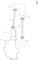
Figure 1 is a schematic view of a power generator system for a heavy vehicle used in a configuration with two driving axles; -
Figure 2 is a cross-section view of a distributor system according to the invention in the configuration inFigure 1 ; -
Figure 3 is a schematic view of a power generator system for a heavy vehicle used in a configuration with three driving axles; -
Figure 4 is a cross-section view of a distributor system according to the invention in the configuration inFigure 3 ; -
Figure 5 is a schematic view of a power generator system for a heavy vehicle used in a configuration with three driving axles; and -
Figure 6 is a cross-section view of a distributor system according to the invention in the configuration inFigure 5 . - The attached figures schematically illustrate a
propulsion unit 1 configured to transmit torque through a mechanical chain tomultiple axles - The
propulsion unit 1 may be an internal combustion engine, a fuel cell system, or a hybrid drive system as known in the art. - The
propulsion unit 1 is connected to at least one axle via atransmission 3, designed to select a specific gearbox, multiple rotatingshafts torque distributor system 5 according to the invention. -
Figures 1 and2 illustrate a configuration with two drivingaxles torque distributor 5 is connected by a first rotatingshaft 4a to thepropulsion unit 1, in the case described via thetransmission 3, and where afirst axle 4a is connected by a second rotatingshaft 4b. - Referring to
Figure 2 , thetorque distributor 5 comprises a casing 6 designed to be supported by a portion fixed to the vehicle's chassis (not illustrated) defining aspace 7 and atransmission assembly 8 housed inside thespace 7. - Clearly, the casing 6 is advantageously constructed from several parts firmly connected together in order to enable the assembly of the
transmission assembly 8 in thespace 7. - The casing 6 defines
multiple openings offs transmission 8. - More specifically, the
distributor system 5 defines six openings and respective power take-offs, preferably in pairs coaxial between them. In particular, the first andsecond opening 9, 10 and the first and second power take-off fourth openings offs sixth openings offs - The axes A, B, and C are, advantageously, parallel to each other and, even more preferably, are parallel to a longitudinal axis of the vehicle.
- In the embodiment in
Figure 2 , where there are two drive axles, two power take-offs offs - In particular, in the embodiment described, the rotating
shaft 4a is connected to the power take-off 15, and the power take-off 19 is connected to theaxle 2a and to theaxle 2b, as described below, via thetransmission 8. - The
transmission 8 essentially comprises afirst support shaft 25 connected to the first power take-off 15, in the case described firmly fixed to it; thisfirst support shaft 25 is connected via a firstdifferential mechanism 26 to asecond support shaft 27. Thesupport shaft 27, in the case described, is firmly fixed to the second power take-off 16. - The
first support shaft 25 is also operationally connected to the fifth and to the sixth power take-off differential mechanism 28. In particular, thefirst support shaft 25 is connected to the seconddifferential mechanism 28 via areduction module 31. - Specifically, the
reduction module 31 comprises arotating shaft 32 supported rotationally free by the casing 6 and advantageously connected to the third and fourth power take-offs shaft 32 supports at least onetoothed wheel 33, in the case described atoothed wheel 33 configured to mesh with the first and seconddifferential mechanism - More specifically, the first
differential mechanism 27 comprises agear train 35 configured to connect togethermultiple planet gears 36 meshing between a pair ofgear hubs 37', 37", respectively left and right. In particular, thegear hubs 37', 37" are cone gear hubs. - Specifically, the left gear hub 37' is connected integrally with the rotation of the
support shaft 25 and is configured to also define anadditional toothing 38 configured to cooperate with thereduction module 31, i.e., with thetoothed wheel 33 described above. - The right gear hub 37'' is, instead, advantageously, firmly connected to the
second support shaft 27 and, thus, second power take-off 16. - Referring to the second
differential mechanism 28, it comprises agear train 41 operationally connected to the sixth power take-off 20, supported rotationally free by the casing 6, and configured to dragmultiple planet gears 42 meshing with a pair ofhubs 43', 43", respectively left and right. In particular, thegear hubs 43', 43" are cone gear hubs and, preferably, the sixth power take-off 20 is firmly carried by thegear train 41. - In particular, the
right hub 43" is connected to a connectingshaft 44 configured to be connected with the rotatingshaft 4b to bring the torque to theaxle 4b via the fifth power take-off 19. In particular, the connectingshaft 44 is housed inside thedifferential mechanism 28, i.e., it passes coaxially to the rotation axis of theplanet gears 42. - On the other hand, the left hub 43' is firmly connected to a connecting
shaft 45 configured to be connected with theaxle 4a. - In particular, the connection of the shaft 45 (and, similarly, even if not illustrated of the shaft 44) is made via a
gear 46 between the connectingshaft 45 and the semiaxes (not visible) of theaxle 2a. In the particular case illustrated, thegear 46 comprising a first toothed wheel 46' firmly connected to the connectingshaft 45 and a secondtoothed wheel 46" operationally connected to the semiaxes of theaxle 2a. Advantageously, thesetoothed wheels 46', 46" are conical toothed wheels. - The connecting
shaft 45 is preferably coaxial and supported by the casing 6 around the connectingshaft 44 of theright hub 43". - The
transmission 8 also comprises locking means 50 configured to lock the first or seconddifferential mechanism space 7. - To greatly summarise, the locking means 50 comprise a
sleeve 51 driven by actuator means 52 and configured to cooperate in contact with adifferential element - In the embodiment illustrated, the locking means 50 for the first
differential mechanism 27 comprise asleeve 51 that can move so as to assume a first condition in which it does not cooperate with thegear train 35 and a second condition in which it cooperates with thegear train 35 to make it selectively integral with the casing. - Instead, the locking means 50 for the second
differential mechanism 28 comprise asleeve 51 that can move so as to assume a first condition in which it does not cooperate with thegear train 41 but cooperates, integrally with the rotation with the left hub 43' and a second condition in which it cooperates with thegear train 41 to make it selectively integral with the rotation with the left hub 43' . - The actuator means 52 illustrated here are advantageously pneumatic, i.e., they comprise a piston that can be driven with compressed air and kept in the position to unlock the differential via elastic means, which are not described further for the sake of brevity.
- In the embodiment of
Figures 3 and4 , the vehicle comprises three drivingaxles Figures 1 and2 , the sixth power take-off 20 is connected to a thirdrotating shaft 4c that connects thetransmission 8 to thethird axle 2c. The thirdrotating shaft 4c can be connected with the semiaxes of thethird axle 2c using a gear similar to thegear 46 described above. - In the embodiment of
Figures 5 and6 , the vehicle comprises four drivingaxles Figures 1 and2 , the sixth power take-off 20 is connected to a thirdrotating shaft 4c that connects thetransmission 8 to thethird axle 2c and the second power take-off 16 is connected to a fourthrotating shaft 4d that connects thetransmission 8 to thefourth axle 2d. The third and fourthrotating shafts fourth axles gear 46 described above. - In all three embodiments, the third and fourth power take-
offs casing 7 or via a gear to the above-mentioned power take-offs offs 17, could be connected to devices designed to use the drive torque for other purposes, such as support equipment for the vehicle's operation, such as hydraulic pumps or motors. - The operation of the embodiments described above is as follows.
- In the embodiment in
Figures 1 and2 , the torque generated by thepower generator 1 is transmitted through therotating shaft 4a to the first power take-off 15 to thefirst support shaft 25. Here, the torque passes to thereduction module 31 and is transferred to thesecond differential mechanism 28. Thefirst support shaft 25 also provides torque to the first differential mechanism that rotates idly. In particular, the torque is transferred between thetoothing 38 and thetoothed wheel 33, which meshes with thegear train 41 and rotates it. Thegear train 41 drags the planet gears 42 that rotate thehubs 43' and 43" that rotate the corresponding connectingshafts gears 46, the semiaxes of the first andsecond axles gear train 41 and theshaft 32, rotating, bring with them the respective power take-offs differential mechanism 28, the connectingshafts - If necessary, the locking means 50 may be activated to lock the
gear train 41, and, thus, the sixth power take-off 20, compared to the left hub 43'. In this way, both the connectingshafts axles - In the embodiment in
Figures 3 and4 , the sixth power take-off is connected via the thirdrotating shaft 4c to athird driving axle 2c and the torque provided according to what was discussed beforehand to thegear train 41 is provided to the semiaxes of thethird axle 2c. If the locking means 50 lock thegear train 41 to the left hub 43', all three connecting shafts would rotate at the same speed. - In the embodiment in
Figures 5 and6 , the sixth power take-off is connected via the thirdrotating shaft 4c to athird driving axle 2c and the torque provided according to what was discussed beforehand to thegear train 41 is provided to the semiaxes of thethird axle 2c. If the locking means 50 lock thegear train 41 to the left hub 43', all three connectingshafts rotating shaft 4d to afourth driving axle 2d that rotates, thanks to thefirst differential mechanism 26 at a different speed compared to that of the otherrotating shafts gear train 35 to the casing 6 so as to have the same torque at output towards thesecond differential mechanism 28 and towards the fourthrotating shaft 2d. Arranging, as a result, the relationships between thereduction module 31 and thesecond differential mechanism 28, it is possible to rotate, if both the locking means are activated, at the same speed. - In all the embodiments, part of the torque may be used connecting the third and/or fourth power take-
off off transmission 8. - From the above, the advantages of a torque distributor system according to the invention are clear.
- The distributor system proposed makes it possible to distribute, in a versatile way, to different axles of a vehicle, making it possible to obtain different vehicle driving axle configurations with the same system.
- In addition, the distributor system proposed makes it possible to connect electric machines for additional support/use of the torque provided by the power generator, or devices to use this torque to the same system.
- Thus, the distributor system according to the invention is particularly versatile, i.e., it is suitable for a large variety of purposes, reducing the costs of manufacturing and enabling a lot of vehicle customisation.
- In addition, the fact that the transmission is housed inside a single space and the fact that the power take-offs can be isolated when not used, increases the service life of the transmission.
- The use of one or more differentials also makes it possible to have axles with equal traction that can be used in the conditions required by specific loading and/or ground situations.
- Finally, it is clear that changes may be made to the torque distributor system, and variations produced thereto, according to this invention that, in any case, do not depart from the scope of protection defined by the claims.
- Clearly, additional mechanical elements not described for brevity may be included.
- The
reduction module 31 and thedifferential mechanisms - Similarly, the arrangement of the power take-offs could vary and additional reduction stages could be included between them.
- The system could also comprise just one differential mechanism or not comprise any of them.
Claims (16)
- - A torque distributor system (5) for distributing the torque coming from a power generator (1) of a vehicle to a plurality of axles (2a, 2b, 2c, 2d) of said vehicle,said distributor system (5) comprising a casing (6) adapted to define a space (7) configured to house a transmission (8), said casing (6) defining a plurality of openings (9, 10, 11, 12, 13, 14) configured to house respective power take offs (15, 16, 17, 18, 19, 20) connected to each other by said transmission (8), a first power take off (15) of said power take offs 15, 16, 17 , 18, 19, 20) being connectable to said power generator (1) and at least a second (19) of said power take-offs (15, 16, 17, 18, 19, 20) being connectable to one or more of said axles ( 2a, 2b, 2c, 2d), the remaining power take-offs being isolated from the external environment by means of covers (21a, 21b, 21c, 21d) carried by said casing (6), wherein said transmission (8) comprises a differential mechanism (28) operatively interposed between said first and said second power take-off (15, 19), said second power take-off (19) comprising a pair of connecting shafts (44, 45) connected to respective outputs of said differential mechanism (28),said system comprising a third power take-off (20) connectable to a third axle (2c) of said vehicle, said third power take-off (20) being operatively connected to a gear train (41) of said mechanism differential (28) and a fourth power take-off (16), said transmission (8) comprising a further differential mechanism (26) operatively interposed between said first and fourth power take-offs (15, 16).
- - The system according to claim 1, wherein said third power take-off (20) is coaxial along a first axis (C) to said second power take-off (19).
- - The system according to claim 1, wherein said fourth power take-off (16) is coaxial along a second axis (A) to said first power take-off (15).
- - The system according to one of claims 1 to 3, wherein said differential mechanism (28) is operatively connected to said further differential mechanism (26) by means of a reduction stage (31).
- - The system according to one of the previous claims, wherein said transmission (8) comprises a reduction stage (31) operatively interposed between said first power take-off (15) and said second power take-off (19).
- The system according to claim 5, wherein the carrier (35) of said differential mechanism (26) is connected via said reduction stage (31) to said further differential mechanism (28).
- - The system according to one of the previous claims, wherein defining a third power take-off (17) operatively interposed between said first and second power take-offs (15, 19), said third power take-off (17) being connectable to a further driving source or a device using the torque supplied by said power generator (1).
- - The system according to one of claims 2 to 10, wherein defining a fourth power take-off (18) operatively interposed between said first and second power take-offs (15, 19), said fourth power take-off (18) being connectable to a further driving source or a device using the torque supplied by said power generator (1).
- - The system according to Claims 10 and 11 in which said third and said fourth power take-off (17) are coaxial to each other along a third axis (B).
- - The system according to claim 7 and 8 or 9, when dependent on claims 5 or 6, in which said third and said fourth power take-off (17) are carried by a support shaft (32) of said reduction stage (31).
- - The system according to claims 2, 3 or 9, in which said axes (A, B, C) are parallel to a longitudinal axis of said vehicle.
- - The system in any one of the preceding claims, wherein each axle (2a, 2b, 2c, 2d) comprises a gear (16) operatively connected to the respective power take-off (19, 20, 16) .
- - The system according to claims one of the preceding claims, wherein said transmission (8) comprises locking means (50) for locking said differential mechanisms (26, 28) .
- - The system according to claim 13, wherein said locking means (50) comprise a sleeve (51) and actuator means (52) configured to move said sleeve (51) so as to make said gear train (41) integral with said differential mechanism (28) to one of said connecting shafts (44, 45).
- - The system according to claim 13 or 14, wherein said locking means (50) comprise a sleeve (51) and actuator means (52) configured to move said sleeve so as to make said gear train (35) integral with said further differential mechanism (28) to said casing (6).
- - A vehicle comprising a power generator (1) capable of generating torque, a plurality of axles (2a, 2b, 2c, 2d) and a torque distributor (5) operatively interposed between said power generator (1) and said axles (2a, 2b, 2c, 2d), said torque distributor (5) being made according to one of the preceding claims.
Applications Claiming Priority (1)
| Application Number | Priority Date | Filing Date | Title |
|---|---|---|---|
| IT102022000002345A IT202200002345A1 (en) | 2022-02-09 | 2022-02-09 | IMPROVED TORQUE DISTRIBUTOR SYSTEM BETWEEN HEAVY VEHICLE AXLES |
Publications (2)
| Publication Number | Publication Date |
|---|---|
| EP4238802A1 true EP4238802A1 (en) | 2023-09-06 |
| EP4238802B1 EP4238802B1 (en) | 2025-04-30 |
Family
ID=81384817
Family Applications (1)
| Application Number | Title | Priority Date | Filing Date |
|---|---|---|---|
| EP23155288.6A Active EP4238802B1 (en) | 2022-02-09 | 2023-02-07 | Improved torque distributor system among axles of a heavy vehicle |
Country Status (2)
| Country | Link |
|---|---|
| EP (1) | EP4238802B1 (en) |
| IT (1) | IT202200002345A1 (en) |
Cited By (1)
| Publication number | Priority date | Publication date | Assignee | Title |
|---|---|---|---|---|
| IT202300020277A1 (en) * | 2023-10-02 | 2025-04-02 | Iveco Spa | IMPROVED TORQUE DISTRIBUTION SYSTEM BETWEEN HEAVY DUTY VEHICLE AXLES |
Citations (3)
| Publication number | Priority date | Publication date | Assignee | Title |
|---|---|---|---|---|
| CN105584357A (en) * | 2016-03-16 | 2016-05-18 | 徐州重型机械有限公司 | Drive axle assembly and engineering vehicle |
| EP3647097A1 (en) * | 2018-08-07 | 2020-05-06 | Viktor Meili AG | Motor vehicle drive |
| CN112413079A (en) * | 2020-11-04 | 2021-02-26 | 长沙桑铼特农业机械设备有限公司 | Transfer case and agricultural machine |
-
2022
- 2022-02-09 IT IT102022000002345A patent/IT202200002345A1/en unknown
-
2023
- 2023-02-07 EP EP23155288.6A patent/EP4238802B1/en active Active
Patent Citations (3)
| Publication number | Priority date | Publication date | Assignee | Title |
|---|---|---|---|---|
| CN105584357A (en) * | 2016-03-16 | 2016-05-18 | 徐州重型机械有限公司 | Drive axle assembly and engineering vehicle |
| EP3647097A1 (en) * | 2018-08-07 | 2020-05-06 | Viktor Meili AG | Motor vehicle drive |
| CN112413079A (en) * | 2020-11-04 | 2021-02-26 | 长沙桑铼特农业机械设备有限公司 | Transfer case and agricultural machine |
Cited By (2)
| Publication number | Priority date | Publication date | Assignee | Title |
|---|---|---|---|---|
| IT202300020277A1 (en) * | 2023-10-02 | 2025-04-02 | Iveco Spa | IMPROVED TORQUE DISTRIBUTION SYSTEM BETWEEN HEAVY DUTY VEHICLE AXLES |
| EP4534318A1 (en) * | 2023-10-02 | 2025-04-09 | Iveco S.P.A. | Improved torque distributor system among axles of a heavy vehicle |
Also Published As
| Publication number | Publication date |
|---|---|
| EP4238802B1 (en) | 2025-04-30 |
| IT202200002345A1 (en) | 2023-08-09 |
Similar Documents
| Publication | Publication Date | Title |
|---|---|---|
| US8403088B2 (en) | Electric axle drive unit | |
| KR102580735B1 (en) | Axle assembly for low-floor vehicles | |
| EP3277530B1 (en) | An electrical axle | |
| EP1832462B1 (en) | Drive force distribution apparatus and method | |
| US20110124460A1 (en) | Electric drive system | |
| CN112752666A (en) | Drive device for an electric drive axle of a motor vehicle | |
| US9353847B2 (en) | Torque vectoring device | |
| US12409717B2 (en) | Compact E-axle assembly | |
| CN115593213A (en) | Electric power assembly for vehicle | |
| JP4891241B2 (en) | Variable torque distributor | |
| CN115195431A (en) | Power transmission for a utility vehicle having an electric axle | |
| CN115704462A (en) | Transmission for a vehicle and drive train having such a transmission | |
| EP4238802B1 (en) | Improved torque distributor system among axles of a heavy vehicle | |
| CN116691302A (en) | Powertrain, electrically driven axle and vehicle | |
| EP4180255B1 (en) | An electric powertrain for a vehicle | |
| CN115704461A (en) | Transmission for a vehicle and drive train having such a transmission | |
| CN115704455A (en) | Transmission for a vehicle and drive train having such a transmission | |
| EP4257388A1 (en) | Improved torque distributor system among axles of a heavy vehicle | |
| JP2991009B2 (en) | Right and left driving force distribution adjustment device for vehicles | |
| CN224103858U (en) | Electric axle drives, electric drive components, and vehicles for vehicles | |
| EP4257401A1 (en) | Improved torque distributor system among axles of a heavy vehicle | |
| EP4534318A1 (en) | Improved torque distributor system among axles of a heavy vehicle | |
| CN223890781U (en) | Driving device for all-wheel drive vehicle and vehicle | |
| EP4257389A1 (en) | Improved torque distribution system among axles of a heavy vehicle | |
| JP4142768B2 (en) | Differential device |
Legal Events
| Date | Code | Title | Description |
|---|---|---|---|
| PUAI | Public reference made under article 153(3) epc to a published international application that has entered the european phase |
Free format text: ORIGINAL CODE: 0009012 |
|
| STAA | Information on the status of an ep patent application or granted ep patent |
Free format text: STATUS: THE APPLICATION HAS BEEN PUBLISHED |
|
| AK | Designated contracting states |
Kind code of ref document: A1 Designated state(s): AL AT BE BG CH CY CZ DE DK EE ES FI FR GB GR HR HU IE IS IT LI LT LU LV MC ME MK MT NL NO PL PT RO RS SE SI SK SM TR |
|
| STAA | Information on the status of an ep patent application or granted ep patent |
Free format text: STATUS: REQUEST FOR EXAMINATION WAS MADE |
|
| 17P | Request for examination filed |
Effective date: 20240219 |
|
| RBV | Designated contracting states (corrected) |
Designated state(s): AL AT BE BG CH CY CZ DE DK EE ES FI FR GB GR HR HU IE IS IT LI LT LU LV MC ME MK MT NL NO PL PT RO RS SE SI SK SM TR |
|
| GRAP | Despatch of communication of intention to grant a patent |
Free format text: ORIGINAL CODE: EPIDOSNIGR1 |
|
| STAA | Information on the status of an ep patent application or granted ep patent |
Free format text: STATUS: GRANT OF PATENT IS INTENDED |
|
| INTG | Intention to grant announced |
Effective date: 20240809 |
|
| GRAJ | Information related to disapproval of communication of intention to grant by the applicant or resumption of examination proceedings by the epo deleted |
Free format text: ORIGINAL CODE: EPIDOSDIGR1 |
|
| STAA | Information on the status of an ep patent application or granted ep patent |
Free format text: STATUS: REQUEST FOR EXAMINATION WAS MADE |
|
| GRAP | Despatch of communication of intention to grant a patent |
Free format text: ORIGINAL CODE: EPIDOSNIGR1 |
|
| STAA | Information on the status of an ep patent application or granted ep patent |
Free format text: STATUS: GRANT OF PATENT IS INTENDED |
|
| INTC | Intention to grant announced (deleted) | ||
| P01 | Opt-out of the competence of the unified patent court (upc) registered |
Free format text: CASE NUMBER: APP_58788/2024 Effective date: 20241028 |
|
| INTG | Intention to grant announced |
Effective date: 20241125 |
|
| GRAS | Grant fee paid |
Free format text: ORIGINAL CODE: EPIDOSNIGR3 |
|
| GRAA | (expected) grant |
Free format text: ORIGINAL CODE: 0009210 |
|
| STAA | Information on the status of an ep patent application or granted ep patent |
Free format text: STATUS: THE PATENT HAS BEEN GRANTED |
|
| AK | Designated contracting states |
Kind code of ref document: B1 Designated state(s): AL AT BE BG CH CY CZ DE DK EE ES FI FR GB GR HR HU IE IS IT LI LT LU LV MC ME MK MT NL NO PL PT RO RS SE SI SK SM TR |
|
| REG | Reference to a national code |
Ref country code: CH Ref legal event code: EP Ref country code: GB Ref legal event code: FG4D |
|
| REG | Reference to a national code |
Ref country code: DE Ref legal event code: R096 Ref document number: 602023003112 Country of ref document: DE |
|
| REG | Reference to a national code |
Ref country code: IE Ref legal event code: FG4D |
|
| REG | Reference to a national code |
Ref country code: NL Ref legal event code: MP Effective date: 20250430 |
|
| REG | Reference to a national code |
Ref country code: AT Ref legal event code: MK05 Ref document number: 1789737 Country of ref document: AT Kind code of ref document: T Effective date: 20250430 |
|
| PG25 | Lapsed in a contracting state [announced via postgrant information from national office to epo] |
Ref country code: PT Free format text: LAPSE BECAUSE OF FAILURE TO SUBMIT A TRANSLATION OF THE DESCRIPTION OR TO PAY THE FEE WITHIN THE PRESCRIBED TIME-LIMIT Effective date: 20250901 Ref country code: FI Free format text: LAPSE BECAUSE OF FAILURE TO SUBMIT A TRANSLATION OF THE DESCRIPTION OR TO PAY THE FEE WITHIN THE PRESCRIBED TIME-LIMIT Effective date: 20250430 Ref country code: ES Free format text: LAPSE BECAUSE OF FAILURE TO SUBMIT A TRANSLATION OF THE DESCRIPTION OR TO PAY THE FEE WITHIN THE PRESCRIBED TIME-LIMIT Effective date: 20250430 |
|
| REG | Reference to a national code |
Ref country code: LT Ref legal event code: MG9D |
|
| PG25 | Lapsed in a contracting state [announced via postgrant information from national office to epo] |
Ref country code: NO Free format text: LAPSE BECAUSE OF FAILURE TO SUBMIT A TRANSLATION OF THE DESCRIPTION OR TO PAY THE FEE WITHIN THE PRESCRIBED TIME-LIMIT Effective date: 20250730 Ref country code: GR Free format text: LAPSE BECAUSE OF FAILURE TO SUBMIT A TRANSLATION OF THE DESCRIPTION OR TO PAY THE FEE WITHIN THE PRESCRIBED TIME-LIMIT Effective date: 20250731 |
|
| PG25 | Lapsed in a contracting state [announced via postgrant information from national office to epo] |
Ref country code: NL Free format text: LAPSE BECAUSE OF FAILURE TO SUBMIT A TRANSLATION OF THE DESCRIPTION OR TO PAY THE FEE WITHIN THE PRESCRIBED TIME-LIMIT Effective date: 20250430 Ref country code: PL Free format text: LAPSE BECAUSE OF FAILURE TO SUBMIT A TRANSLATION OF THE DESCRIPTION OR TO PAY THE FEE WITHIN THE PRESCRIBED TIME-LIMIT Effective date: 20250430 |
|
| PG25 | Lapsed in a contracting state [announced via postgrant information from national office to epo] |
Ref country code: BG Free format text: LAPSE BECAUSE OF FAILURE TO SUBMIT A TRANSLATION OF THE DESCRIPTION OR TO PAY THE FEE WITHIN THE PRESCRIBED TIME-LIMIT Effective date: 20250430 |
|
| PG25 | Lapsed in a contracting state [announced via postgrant information from national office to epo] |
Ref country code: HR Free format text: LAPSE BECAUSE OF FAILURE TO SUBMIT A TRANSLATION OF THE DESCRIPTION OR TO PAY THE FEE WITHIN THE PRESCRIBED TIME-LIMIT Effective date: 20250430 |
|
| PG25 | Lapsed in a contracting state [announced via postgrant information from national office to epo] |
Ref country code: AT Free format text: LAPSE BECAUSE OF FAILURE TO SUBMIT A TRANSLATION OF THE DESCRIPTION OR TO PAY THE FEE WITHIN THE PRESCRIBED TIME-LIMIT Effective date: 20250430 |
|
| PG25 | Lapsed in a contracting state [announced via postgrant information from national office to epo] |
Ref country code: RS Free format text: LAPSE BECAUSE OF FAILURE TO SUBMIT A TRANSLATION OF THE DESCRIPTION OR TO PAY THE FEE WITHIN THE PRESCRIBED TIME-LIMIT Effective date: 20250731 |
|
| PG25 | Lapsed in a contracting state [announced via postgrant information from national office to epo] |
Ref country code: IS Free format text: LAPSE BECAUSE OF FAILURE TO SUBMIT A TRANSLATION OF THE DESCRIPTION OR TO PAY THE FEE WITHIN THE PRESCRIBED TIME-LIMIT Effective date: 20250830 |
|
| PG25 | Lapsed in a contracting state [announced via postgrant information from national office to epo] |
Ref country code: LV Free format text: LAPSE BECAUSE OF FAILURE TO SUBMIT A TRANSLATION OF THE DESCRIPTION OR TO PAY THE FEE WITHIN THE PRESCRIBED TIME-LIMIT Effective date: 20250430 |
|
| PG25 | Lapsed in a contracting state [announced via postgrant information from national office to epo] |
Ref country code: DK Free format text: LAPSE BECAUSE OF FAILURE TO SUBMIT A TRANSLATION OF THE DESCRIPTION OR TO PAY THE FEE WITHIN THE PRESCRIBED TIME-LIMIT Effective date: 20250430 Ref country code: SM Free format text: LAPSE BECAUSE OF FAILURE TO SUBMIT A TRANSLATION OF THE DESCRIPTION OR TO PAY THE FEE WITHIN THE PRESCRIBED TIME-LIMIT Effective date: 20250430 |
|
| PG25 | Lapsed in a contracting state [announced via postgrant information from national office to epo] |
Ref country code: CZ Free format text: LAPSE BECAUSE OF FAILURE TO SUBMIT A TRANSLATION OF THE DESCRIPTION OR TO PAY THE FEE WITHIN THE PRESCRIBED TIME-LIMIT Effective date: 20250430 |
|
| PG25 | Lapsed in a contracting state [announced via postgrant information from national office to epo] |
Ref country code: EE Free format text: LAPSE BECAUSE OF FAILURE TO SUBMIT A TRANSLATION OF THE DESCRIPTION OR TO PAY THE FEE WITHIN THE PRESCRIBED TIME-LIMIT Effective date: 20250430 |
|
| PG25 | Lapsed in a contracting state [announced via postgrant information from national office to epo] |
Ref country code: SK Free format text: LAPSE BECAUSE OF FAILURE TO SUBMIT A TRANSLATION OF THE DESCRIPTION OR TO PAY THE FEE WITHIN THE PRESCRIBED TIME-LIMIT Effective date: 20250430 |
|
| REG | Reference to a national code |
Ref country code: DE Ref legal event code: R097 Ref document number: 602023003112 Country of ref document: DE |
|
| PLBE | No opposition filed within time limit |
Free format text: ORIGINAL CODE: 0009261 |
|
| STAA | Information on the status of an ep patent application or granted ep patent |
Free format text: STATUS: NO OPPOSITION FILED WITHIN TIME LIMIT |
|
| REG | Reference to a national code |
Ref country code: CH Ref legal event code: L10 Free format text: ST27 STATUS EVENT CODE: U-0-0-L10-L00 (AS PROVIDED BY THE NATIONAL OFFICE) Effective date: 20260311 |
|
| 26N | No opposition filed |
Effective date: 20260202 |
|
| PGFP | Annual fee paid to national office [announced via postgrant information from national office to epo] |
Ref country code: DE Payment date: 20260220 Year of fee payment: 4 |
|
| PGFP | Annual fee paid to national office [announced via postgrant information from national office to epo] |
Ref country code: IT Payment date: 20260228 Year of fee payment: 4 |
|
| PGFP | Annual fee paid to national office [announced via postgrant information from national office to epo] |
Ref country code: FR Payment date: 20260227 Year of fee payment: 4 |