EP4238749A1 - Tire sound absorbing material crimping device - Google Patents
Tire sound absorbing material crimping device Download PDFInfo
- Publication number
- EP4238749A1 EP4238749A1 EP23155006.2A EP23155006A EP4238749A1 EP 4238749 A1 EP4238749 A1 EP 4238749A1 EP 23155006 A EP23155006 A EP 23155006A EP 4238749 A1 EP4238749 A1 EP 4238749A1
- Authority
- EP
- European Patent Office
- Prior art keywords
- tire
- absorbing material
- sound absorbing
- crimping
- unit
- Prior art date
- Legal status (The legal status is an assumption and is not a legal conclusion. Google has not performed a legal analysis and makes no representation as to the accuracy of the status listed.)
- Granted
Links
Images



Classifications
-
- B—PERFORMING OPERATIONS; TRANSPORTING
- B29—WORKING OF PLASTICS; WORKING OF SUBSTANCES IN A PLASTIC STATE IN GENERAL
- B29D—PRODUCING PARTICULAR ARTICLES FROM PLASTICS OR FROM SUBSTANCES IN A PLASTIC STATE
- B29D30/00—Producing pneumatic or solid tyres or parts thereof
- B29D30/0061—Accessories, details or auxiliary operations not otherwise provided for
-
- B—PERFORMING OPERATIONS; TRANSPORTING
- B60—VEHICLES IN GENERAL
- B60C—VEHICLE TYRES; TYRE INFLATION; TYRE CHANGING; CONNECTING VALVES TO INFLATABLE ELASTIC BODIES IN GENERAL; DEVICES OR ARRANGEMENTS RELATED TO TYRES
- B60C19/00—Tyre parts or constructions not otherwise provided for
- B60C19/002—Noise damping elements provided in the tyre structure or attached thereto, e.g. in the tyre interior
-
- B—PERFORMING OPERATIONS; TRANSPORTING
- B29—WORKING OF PLASTICS; WORKING OF SUBSTANCES IN A PLASTIC STATE IN GENERAL
- B29D—PRODUCING PARTICULAR ARTICLES FROM PLASTICS OR FROM SUBSTANCES IN A PLASTIC STATE
- B29D30/00—Producing pneumatic or solid tyres or parts thereof
- B29D30/06—Pneumatic tyres or parts thereof (e.g. produced by casting, moulding, compression moulding, injection moulding, centrifugal casting)
- B29D30/0681—Parts of pneumatic tyres; accessories, auxiliary operations
-
- B—PERFORMING OPERATIONS; TRANSPORTING
- B29—WORKING OF PLASTICS; WORKING OF SUBSTANCES IN A PLASTIC STATE IN GENERAL
- B29D—PRODUCING PARTICULAR ARTICLES FROM PLASTICS OR FROM SUBSTANCES IN A PLASTIC STATE
- B29D30/00—Producing pneumatic or solid tyres or parts thereof
- B29D30/06—Pneumatic tyres or parts thereof (e.g. produced by casting, moulding, compression moulding, injection moulding, centrifugal casting)
- B29D30/0681—Parts of pneumatic tyres; accessories, auxiliary operations
- B29D2030/0682—Inner liners
Definitions
- the present invention relates to a tire sound absorbing material crimping device, and more particularly, to a tire sound absorbing material crimping device intended to uniformly and firmly press a sound absorbing material adhered to an inner liner portion of a tire.
- a raw material undergoes refining, rolling, extrusion, and bead processes, and is prepared into a green tire through a molding process, and then is manufactured into a finished tire through a vulcanization process.
- Compressed air is injected into the finished tire, such that noise is generated inside the tire during driving, which is called resonance.
- This noise causes a deterioration in riding comfort for the driver who drives a vehicle and passengers inside the vehicle.
- a sound absorbing material is adhered to an inner surface of the tire, more precisely, to an inner liner portion located on a side opposite to the tire tread in a circumferential direction.
- an adhesive is applied to a portion where the sound absorbing material is to be adhered on the tire inner liner, and the sound absorbing material is attached thereto. Then, the sound absorbing material is firmly fixed to the adhesive by pressing the sound absorbing material through a separate sound absorbing material adhesion device.
- Korean Patent Registration No. 10-1775797 discloses "a tire sound absorbing material fixing structure having a sound absorbing material fixing band and a tire manufactured including the same.” More specifically, a fixing method of the tire sound absorbing material disclosed in this patent includes the steps of: extending a sound absorbing material fixing band upward by applying a force to a pressing part; positioning a sound absorbing material on a lower portion of the pressing part; applying a pressure downward to the sound absorbing material while the sound absorbing material fixing band contracts by removing the applied force that extends the sound absorbing material fixing band; maintaining a close contact state between the sound absorbing material and an inner surface of the tire by the sound absorbing material fixing band; positioning the sound absorbing material on the lower portion of the pressing part of the adjacent sound absorbing material fixing band by extending upward the adjacent sound absorbing material fixing band.
- the above steps are repeatedly performed until the sound absorbing material is fixedly adhered to the entire sound absorbing material fixing band formed in the circumfer
- a tire sound absorbing material crimping device including: a fixing unit configured to align a center of a tire transported by a tire conveying unit and position the tire; a crimping unit configured to press a sound absorbing material while expanding radially toward the sound absorbing material adhered to an inner liner of the tire fixed to the fixing unit; and a motor unit connected to an upper portion of the crimping unit and configured to raise and lower the crimping unit toward the tire.
- the crimping unit may include: a first plate having a predetermined thickness and area; a plurality of main frames formed on a lower portion of the first plate and extending or contracting radially based on a central axis of the first plate; and a crimping ring which connects lower portions of the plurality of main frames with each other and is configured to press the sound absorbing material of the tire by expanding or contracting a diameter thereof according to an operation of radially expanding or contracting the main frames.
- the crimping unit further may include a servomotor installed on the first plate, and the servomotor may include a first gear formed on a lower portion thereof, and each of the main frames may include a second gear formed on an upper one side thereof to be meshed with the first gear, such that when operating the servomotor, the main frames are radially expanded and contracted while the meshed first and second gears are rotated.
- the motor unit may be arranged above the second plate disposed above the first plate, and may include a motor axis having a drive gear formed thereon, wherein a plurality of shafts are arranged above the second plate, which respectively has one end fixed to the first plate and the other end extending upward from the first plate by penetrating the second plate and having a driven gear formed on an outer circumferential surface to be meshed with the drive gear, and when operating the motor unit, the plurality of shafts connected to the first plate are lowered in a longitudinal direction thereof by the driven gear rotated by the drive gear, such that the crimping unit is moved to the tire.
- the crimping ring may include a plurality of segments connected to lower portions of the plurality of main frames, respectively, and having a predetermined curvature, wherein the plurality of segments include: first segments located outside in a radial direction and having guide pins formed at both ends thereof; and second segments located inside in the radial direction and having guide grooves extending in a circumferential direction, into which the guide pins of the first segment are inserted, wherein the second segments are configured to expand and contract an entire diameter of the crimping ring while the guide pins are guided along the guide grooves.
- the main frame may include: an upper frame into which a screw part of a ball screw expanding radially from the second gear is inserted; a center frame extending downward from the upper frame; and a lower frame expanding radially from a lower end of the center frame.
- the present invention by using a mechanical device capable of accurately and firmly pressing the sound absorbing material adhered to the inner liner of the tire, it is possible to solve the problem that the sound absorbing material is not uniformly adhered due to a tread curvature and to produce a product with constant quality.
- the crimping condition can be changed for each tire size, such that the tire sound absorbing material crimping device may be used universally for all tires of various sizes.
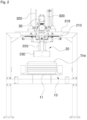
- a tire sound absorbing material crimping device includes: a fixing unit 10 configured to align a center of a tire transported by a tire conveying unit 11 and position the tire; a crimping unit 20 configured to press a sound absorbing material while expanding radially toward the sound absorbing material adhered to an inner liner of the tire fixed to the fixing unit 10; and a motor unit 30 connected to an upper portion of the crimping unit 20 and configured to raise and lower the crimping unit 20 toward the tire.
- the tire conveying unit 11 is configured to transfer the tire by a transfer device such as a conveyor belt in a state where a sound absorbing material is adhered to the tire, preferably to an inner liner of the tire.
- the tire transported by the tire conveying unit 11 is stopped with being positioned below the tire sound absorbing material crimping device.
- the fixing unit 10 fixes an outer periphery of the tire to align the center while preventing the tire from being separated.
- the fixing unit 10 according to an embodiment includes a plurality of fixing rods which are located above the tire conveying unit 11, extend upward in a width direction of the outer circumferential surface of the tire, and are configured to move toward a central axis of the transferred tire, and align the center of the tire while supporting the outer circumferential surface thereof.
- the crimping unit 20 presses the sound absorption material while expanding radially toward the sound absorption material adhered to the inner liner of the tire fixed to the fixing unit 10.
- the crimping unit 20 may include a first plate 210 having a predetermined thickness and area; a plurality of main frames 220 formed on a lower portion of the first plate 210 and expanding or contracting radially based on a central axis of the first plate 210; and a crimping ring 230 which connects lower portions of the plurality of main frames 220 with each other and is configured to press the sound absorbing material of the tire by expanding or contracting a diameter thereof according to an operation of radially expanding or contracting the main frames 220.
- the sound absorbing material adhered to the inner liner of the tire is pressed by the crimping unit 20, and the detailed configuration of the crimping unit 20 will be described below.
- the first plate 210 having a predetermined thickness and area may be installed on the top, preferably formed in a disk shape, and have a diameter corresponding to a length that the main frame 220 to be described below expands to the maximum in the radial direction.
- the main frame 220 is formed on the lower portion of the first plate 210 and may radially expand or contract based on the central axis of the first plate 210.
- the main frame 220 may be composed of a plurality of frames which are radially expanded or contracted based on a central axis of the first plate 210 and a central axis of the tire defined by fixing the position of the tire and aligning the center by the fixing unit 10.
- the plurality of main frames are arranged side by side in a circumferential circumference based on the central axis of the first plate 210, and can be expanded or contracted radially during operation.
- the crimping ring 230 may press the sound absorbing material of the tire by expanding or contracting the diameter thereof according to the operation of radially expanding or contracting the main frames 220.
- the diameter of the crimping ring 230 formed in a ring shape by connecting the lower portions of the plurality of main frames 220 is also expanded or reduced.
- the sound absorbing material adhered to the inner liner portion of the tire may be firmly pressed.
- a length of the crimping ring 230 in a width direction and a length of the sound absorbing material in the width direction are formed to correspond to each other, such that all regions of the sound absorbing material can be uniformly pressed.
- the crimping ring 230 is connected to each of the lower portions of the plurality of main frames 220, and includes a plurality of segments 231 having a predetermined curvature.
- the plurality of segments 231 may include: first segments 233 located outside in a radial direction and having guide pins 234 formed at both ends thereof; and second segments 235 located inside in the radial direction and having guide grooves 236 extending in the circumferential direction, into which the guide pins 234 of the first segment 233 are inserted, wherein the second segments 235 are configured to expand and contract an entire diameter of the crimping ring 230 while the guide pins 234 are guided along the guide grooves 236.
- the crimping ring 230 may include the plurality of segments 231 having a predetermined curvature.
- the plurality of segments 231 have the same curvature and are interconnected to form one circle, and the first segment 233 located outside in the radial direction and the second segment 235 located inside in the radial direction are alternately arranged, and some regions at both ends of these segments are overlapped with each other.
- the guide pins 234 are formed at both ends of each of the first segments 233, and guide grooves 236 are formed in each of the second segment 235, into which the guide pins 234 can be inserted and guided in the circumferential direction. Accordingly, when the main frames 220 are expanded, the entire first segments 233 and the second segments 235 are radially expanded as the guide pins 234 move along the guide grooves 236. As the plurality of segments 231 are expanded toward the sound absorbing material to press the sound absorbing material, uniform crimping may be achieved over an entire area of the sound absorbing material through the above process.
- the crimping unit 20 further includes a servomotor 240 installed on the first plate 210.
- the servomotor 240 includes a first gear 250 formed on a lower portion thereof, and each of the main frames 220 includes a second gear 260 formed on an upper one side thereof to be meshed with the first gear 250. Therefore, when operating the servomotor 240, the main frames 220 can be radially expanded and contracted while the meshed first and second gears are rotated.
- the first gear 250 is a gear rotating about the axis of the servomotor 240
- the second gear 260 is a gear connected to each of the main frames 220 and rotated by the first gear 250 with being meshed.
- These gear are formed in a bevel gear (or spiral bevel gear) type in which the first gear 250 is formed as a ring gear, and the second gear 260 is formed as a pinion gear. That is, due to these gears of which axes are arranged at a predetermined angle, rotation of the shaft of the servomotor 240 is transmitted to the second gear 260 through the first gear 250, such that the main frames 220 can be radially expanded or contracted. Accordingly, when rotating the shaft of the servomotor 240, the second gears 260 of the main frames 220 are rotated due to the rotation of the first gear 250, and the main frames 220 may be radially expanded or contracted.
- the main frame 220 may include: an upper frame 221 into which a screw part 222 of a ball screw expanding radially from the second gear 260 is inserted; a center frame 223 extending downward from the upper frame 221; and a lower frame 225 extending radially from a lower end of the center frame 223.
- the ball screw is a motion conversion device that converts rotational motion into linear motion.
- the ball screw may have a structure in which one end of the second gear 260 is meshed with the first gear 250 and the other end of the screw part 222 extends radially from the second gear 260, wherein the upper frame 221 having an insertion hole into which the screw part 222 is inserted functions as a nut part of the ball screw. Therefore, when the second gear 260 rotates, the upper frame 221 moves linearly through the nut part while the screw part 222 is rotated, such that the main frame 220 moves linearly in a longitudinal direction of the screw, that is, in the radial direction.
- the linear motion of the screw part 222 is transferred from the upper frame 221 to the center frame 223 extending vertically downward, and then to the lower frame 225 expanding radially and horizontally from the center frame 223, such that the above-described plurality of segments 231 installed outside the lower frames 225 can be radially expanded or contracted.
- the motor unit 30 includes a plurality of shafts 320 arranged above the second plate 310, which respectively has one end fixed to the first plate 210 and the other end extending upward from the first plate 210 by penetrating the second plate 310.
- the motor unit 30 and the shafts 320 are operatively connected with each other through a gear mechanism to be described below, such that when operating the motor unit 30, the plurality of shafts 320 connected to the first plate 210 are lowered in the longitudinal direction thereof by an operation of the gear mechanism, and the crimping unit 20 is moved to the tire.
- a process of lowering the crimping unit 20 toward the transferred tire before the process of radially expanding or contracting the crimping unit 20 inside the tire and a process of raising the crimping unit 20 again after the crimping is completed will be described below.
- the motor unit 30 configured to raise and lower the crimping unit 20 may include a motor axis having a drive gear formed thereon, and may be arranged above the second plate 310 having a predetermined thickness and area disposed above the first plate 210.
- the plurality of shafts 320 having one end fixed to the first plate 210 and the other end extending upward by penetrating the second plate 310 may have a driven gear formed on an outer circumferential surface to be meshed with the drive gear.
- the drive gear rotates by the motor axis arranged in parallel in the horizontal direction, and the driven gear of the shaft 320 meshed with the drive gear is rotated to move the shaft 320 up and down.
- the crimping unit 20 is raised or lowered toward the tire.
- the plurality of shafts 320 may be installed at a predetermined distance about the motor unit 30, and preferably has a structure for raising and lowering the crimping unit 20 while maintaining balance as a whole.
Landscapes
- Engineering & Computer Science (AREA)
- Mechanical Engineering (AREA)
- Tires In General (AREA)
- Tyre Moulding (AREA)
Abstract
Description
- This application claims the priority benefit of
Korean Patent Application No. 10-2022-0026885 filed on March 2, 2022 - The present invention relates to a tire sound absorbing material crimping device, and more particularly, to a tire sound absorbing material crimping device intended to uniformly and firmly press a sound absorbing material adhered to an inner liner portion of a tire.
- Unless otherwise indicated herein, the contents described in this section are not prior art to the claims of the present application, and inclusion in this section is not admitted to be the prior art.
- Generally, in the manufacture of a tire, a raw material undergoes refining, rolling, extrusion, and bead processes, and is prepared into a green tire through a molding process, and then is manufactured into a finished tire through a vulcanization process. Compressed air is injected into the finished tire, such that noise is generated inside the tire during driving, which is called resonance. This noise causes a deterioration in riding comfort for the driver who drives a vehicle and passengers inside the vehicle. In order to reduce this resonance of the tire, a sound absorbing material is adhered to an inner surface of the tire, more precisely, to an inner liner portion located on a side opposite to the tire tread in a circumferential direction. As a method of adhering a sound absorbing material, first, an adhesive is applied to a portion where the sound absorbing material is to be adhered on the tire inner liner, and the sound absorbing material is attached thereto. Then, the sound absorbing material is firmly fixed to the adhesive by pressing the sound absorbing material through a separate sound absorbing material adhesion device.
- In this regard,
Korean Patent Registration No. 10-1775797 (published on September 6, 2017 - However, when using the fixing structure of the tire sound absorbing material obtained by the above method, in the process of repeatedly performing the steps of pressing the pressing part, positioning it on the sound absorbing material, applying pressure downward toward the sound absorbing material, and adhering to the sound absorbing material, a worker should perform the work manually without an additional auxiliary machine or device for fixing the sound absorbing material fixing band. Accordingly, the process itself takes a lot of time and requires considerable effort and labor, and as the process is repeatedly performed, a deviation may occur in the adhesion location or strength, thereby resulting in a problem in that quality of the finished tire may be deteriorated.
- It is an object of the present invention to provide a tire sound absorbing material crimping device intended to uniformly and firmly press the sound absorbing material adhered to an inner liner portion of a tire.
- In addition, it is not limited to the technical problems as described above, and it is obvious that another technical problem may be derived from the following description.
- To achieve the above objects, according to an aspect of the present invention, there is provided a tire sound absorbing material crimping device including: a fixing unit configured to align a center of a tire transported by a tire conveying unit and position the tire; a crimping unit configured to press a sound absorbing material while expanding radially toward the sound absorbing material adhered to an inner liner of the tire fixed to the fixing unit; and a motor unit connected to an upper portion of the crimping unit and configured to raise and lower the crimping unit toward the tire.
- According to a preferred feature of the present invention, the crimping unit may include: a first plate having a predetermined thickness and area; a plurality of main frames formed on a lower portion of the first plate and extending or contracting radially based on a central axis of the first plate; and a crimping ring which connects lower portions of the plurality of main frames with each other and is configured to press the sound absorbing material of the tire by expanding or contracting a diameter thereof according to an operation of radially expanding or contracting the main frames.
- According to a preferred feature of the present invention, the crimping unit further may include a servomotor installed on the first plate, and the servomotor may include a first gear formed on a lower portion thereof, and each of the main frames may include a second gear formed on an upper one side thereof to be meshed with the first gear, such that when operating the servomotor, the main frames are radially expanded and contracted while the meshed first and second gears are rotated.
- According to a preferred feature of the present invention, the motor unit may be arranged above the second plate disposed above the first plate, and may include a motor axis having a drive gear formed thereon, wherein a plurality of shafts are arranged above the second plate, which respectively has one end fixed to the first plate and the other end extending upward from the first plate by penetrating the second plate and having a driven gear formed on an outer circumferential surface to be meshed with the drive gear, and when operating the motor unit, the plurality of shafts connected to the first plate are lowered in a longitudinal direction thereof by the driven gear rotated by the drive gear, such that the crimping unit is moved to the tire.
- According to a preferred feature of the present invention, the crimping ring may include a plurality of segments connected to lower portions of the plurality of main frames, respectively, and having a predetermined curvature, wherein the plurality of segments include: first segments located outside in a radial direction and having guide pins formed at both ends thereof; and second segments located inside in the radial direction and having guide grooves extending in a circumferential direction, into which the guide pins of the first segment are inserted, wherein the second segments are configured to expand and contract an entire diameter of the crimping ring while the guide pins are guided along the guide grooves.
- According to a preferred feature of the present invention, the main frame may include: an upper frame into which a screw part of a ball screw expanding radially from the second gear is inserted; a center frame extending downward from the upper frame; and a lower frame expanding radially from a lower end of the center frame.
- According to the present invention, by using a mechanical device capable of accurately and firmly pressing the sound absorbing material adhered to the inner liner of the tire, it is possible to solve the problem that the sound absorbing material is not uniformly adhered due to a tread curvature and to produce a product with constant quality.
- In addition, according to the present invention, by pressing and fixing the sound absorbing material without a separate configuration adhered to the sound absorbing material, it is possible to block additional noise generating factors.
- Further, according to the present invention, the crimping condition can be changed for each tire size, such that the tire sound absorbing material crimping device may be used universally for all tires of various sizes.
- The effects of the present invention are not limited to the above advantages, and those skilled in the art should understand that it includes all effects that can be deduced from the detailed description of the present invention or the configurations of the invention described in the claims.
- The above and other objects, features and other advantages of the present invention will be more clearly understood from the following detailed description taken in conjunction with the accompanying drawings, in which:
-
FIG. 1 is a perspective view illustrating a tire sound absorbing material crimping device according to an embodiment of the present invention; -
FIG. 2 is a front view illustrating the tire sound absorbing material crimping device according to an embodiment of the present invention; -
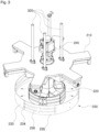
FIG. 3 is a detailed view of a crimping unit illustrating a state where a crimping ring is contracted and expanded in the tire sound absorbing material crimping device according to an embodiment of the present invention; -
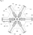
FIG. 4 is an upper cross-sectional view of the crimping unit in the tire sound absorbing material crimping device according to an embodiment of the present invention; -
FIG. 5 is a perspective view illustrating a state where the contracted crimping ring is expanded in the tire sound absorbing material crimping device according to an embodiment of the present invention; and -
FIG. 6 is a perspective view illustrating an operating state of the crimping unit in the tire sound absorbing material crimping device according to an embodiment of the present invention. - Hereinafter, configurations, operations, and effects of an apparatus for disinfecting a robot according to preferred embodiments will be described with reference to the accompanying drawings. For reference, in the drawings described below, each component is omitted or schematically illustrated for convenience and clarity, and the size of each component does not reflect an actual size. In addition, the same reference numerals are denoted to the same components throughout the specification, and reference numerals for the same components in individual drawings will be omitted.
- A tire sound absorbing material crimping device according to an embodiment of the present invention includes: a
fixing unit 10 configured to align a center of a tire transported by atire conveying unit 11 and position the tire; acrimping unit 20 configured to press a sound absorbing material while expanding radially toward the sound absorbing material adhered to an inner liner of the tire fixed to thefixing unit 10; and amotor unit 30 connected to an upper portion of thecrimping unit 20 and configured to raise and lower thecrimping unit 20 toward the tire. - The
tire conveying unit 11 is configured to transfer the tire by a transfer device such as a conveyor belt in a state where a sound absorbing material is adhered to the tire, preferably to an inner liner of the tire. The tire transported by thetire conveying unit 11 is stopped with being positioned below the tire sound absorbing material crimping device. Thereafter, thefixing unit 10 fixes an outer periphery of the tire to align the center while preventing the tire from being separated. Thefixing unit 10 according to an embodiment includes a plurality of fixing rods which are located above thetire conveying unit 11, extend upward in a width direction of the outer circumferential surface of the tire, and are configured to move toward a central axis of the transferred tire, and align the center of the tire while supporting the outer circumferential surface thereof. - Next, the
crimping unit 20 presses the sound absorption material while expanding radially toward the sound absorption material adhered to the inner liner of the tire fixed to thefixing unit 10. - According to a preferred feature of the present invention, the
crimping unit 20 may include afirst plate 210 having a predetermined thickness and area; a plurality ofmain frames 220 formed on a lower portion of thefirst plate 210 and expanding or contracting radially based on a central axis of thefirst plate 210; and acrimping ring 230 which connects lower portions of the plurality ofmain frames 220 with each other and is configured to press the sound absorbing material of the tire by expanding or contracting a diameter thereof according to an operation of radially expanding or contracting themain frames 220. - The sound absorbing material adhered to the inner liner of the tire is pressed by the
crimping unit 20, and the detailed configuration of thecrimping unit 20 will be described below. - First, the
first plate 210 having a predetermined thickness and area may be installed on the top, preferably formed in a disk shape, and have a diameter corresponding to a length that themain frame 220 to be described below expands to the maximum in the radial direction. - The
main frame 220 is formed on the lower portion of thefirst plate 210 and may radially expand or contract based on the central axis of thefirst plate 210. Themain frame 220 may be composed of a plurality of frames which are radially expanded or contracted based on a central axis of thefirst plate 210 and a central axis of the tire defined by fixing the position of the tire and aligning the center by thefixing unit 10. Preferably, the plurality of main frames are arranged side by side in a circumferential circumference based on the central axis of thefirst plate 210, and can be expanded or contracted radially during operation. - In addition, the crimping
ring 230 may press the sound absorbing material of the tire by expanding or contracting the diameter thereof according to the operation of radially expanding or contracting themain frames 220. When themain frame 220 is radially expanded or contracted during operation, the diameter of the crimpingring 230 formed in a ring shape by connecting the lower portions of the plurality ofmain frames 220 is also expanded or reduced. Herein, as the diameter of the crimpingring 230 is expanded, the sound absorbing material adhered to the inner liner portion of the tire may be firmly pressed. Preferably, a length of thecrimping ring 230 in a width direction and a length of the sound absorbing material in the width direction are formed to correspond to each other, such that all regions of the sound absorbing material can be uniformly pressed. - According to a preferred feature of the present invention, the
crimping ring 230 is connected to each of the lower portions of the plurality ofmain frames 220, and includes a plurality ofsegments 231 having a predetermined curvature. The plurality ofsegments 231 may include:first segments 233 located outside in a radial direction and havingguide pins 234 formed at both ends thereof; andsecond segments 235 located inside in the radial direction and havingguide grooves 236 extending in the circumferential direction, into which theguide pins 234 of thefirst segment 233 are inserted, wherein thesecond segments 235 are configured to expand and contract an entire diameter of thecrimping ring 230 while theguide pins 234 are guided along theguide grooves 236. - The crimping
ring 230, more precisely, the crimpingring 230 connected to the lower portions of the plurality ofmain frames 220 and formed in a ring shape as a whole may include the plurality ofsegments 231 having a predetermined curvature. Herein, the plurality ofsegments 231 have the same curvature and are interconnected to form one circle, and thefirst segment 233 located outside in the radial direction and thesecond segment 235 located inside in the radial direction are alternately arranged, and some regions at both ends of these segments are overlapped with each other. Theguide pins 234 are formed at both ends of each of thefirst segments 233, andguide grooves 236 are formed in each of thesecond segment 235, into which theguide pins 234 can be inserted and guided in the circumferential direction. Accordingly, when themain frames 220 are expanded, the entirefirst segments 233 and thesecond segments 235 are radially expanded as theguide pins 234 move along theguide grooves 236. As the plurality ofsegments 231 are expanded toward the sound absorbing material to press the sound absorbing material, uniform crimping may be achieved over an entire area of the sound absorbing material through the above process. - According to a preferred feature of the present invention, the crimping
unit 20 further includes aservomotor 240 installed on thefirst plate 210. Theservomotor 240 includes afirst gear 250 formed on a lower portion thereof, and each of themain frames 220 includes asecond gear 260 formed on an upper one side thereof to be meshed with thefirst gear 250. Therefore, when operating theservomotor 240, themain frames 220 can be radially expanded and contracted while the meshed first and second gears are rotated. - An embodiment for radially expanding and contracting the
main frame 220 will be described below. First, when thefirst gear 250 of theservomotor 240 installed on thefirst plate 210 is rotated in one direction about an axis thereof, themain frames 220 are radially expanded by thesecond gear 260 meshed with thefirst gear 250, whereas when rotated in the opposite direction, they are radially contracted. When operating theservomotor 240, thefirst gear 250 formed on the lower portion of theservomotor 240 and thesecond gear 260 formed on the upper one side of each of themain frames 220 are rotated with being meshed, thus to move themain frames 220 radially. More specifically, thefirst gear 250 is a gear rotating about the axis of theservomotor 240, and thesecond gear 260 is a gear connected to each of themain frames 220 and rotated by thefirst gear 250 with being meshed. These gear are formed in a bevel gear (or spiral bevel gear) type in which thefirst gear 250 is formed as a ring gear, and thesecond gear 260 is formed as a pinion gear. That is, due to these gears of which axes are arranged at a predetermined angle, rotation of the shaft of theservomotor 240 is transmitted to thesecond gear 260 through thefirst gear 250, such that themain frames 220 can be radially expanded or contracted. Accordingly, when rotating the shaft of theservomotor 240, thesecond gears 260 of themain frames 220 are rotated due to the rotation of thefirst gear 250, and themain frames 220 may be radially expanded or contracted. - According to a preferred feature of the present invention, the
main frame 220 may include: anupper frame 221 into which ascrew part 222 of a ball screw expanding radially from thesecond gear 260 is inserted; acenter frame 223 extending downward from theupper frame 221; and alower frame 225 extending radially from a lower end of thecenter frame 223. - Herein, the ball screw is a motion conversion device that converts rotational motion into linear motion. The ball screw may have a structure in which one end of the
second gear 260 is meshed with thefirst gear 250 and the other end of thescrew part 222 extends radially from thesecond gear 260, wherein theupper frame 221 having an insertion hole into which thescrew part 222 is inserted functions as a nut part of the ball screw. Therefore, when thesecond gear 260 rotates, theupper frame 221 moves linearly through the nut part while thescrew part 222 is rotated, such that themain frame 220 moves linearly in a longitudinal direction of the screw, that is, in the radial direction. According to the structure of the ball screw, the linear motion of thescrew part 222 is transferred from theupper frame 221 to thecenter frame 223 extending vertically downward, and then to thelower frame 225 expanding radially and horizontally from thecenter frame 223, such that the above-described plurality ofsegments 231 installed outside thelower frames 225 can be radially expanded or contracted. - Next, the
motor unit 30 connected to the upper portion of the crimpingunit 20 and configured to raise and lower the crimpingunit 20 toward the tire will be described. - Herein, the
motor unit 30 includes a plurality ofshafts 320 arranged above thesecond plate 310, which respectively has one end fixed to thefirst plate 210 and the other end extending upward from thefirst plate 210 by penetrating thesecond plate 310. Themotor unit 30 and theshafts 320 are operatively connected with each other through a gear mechanism to be described below, such that when operating themotor unit 30, the plurality ofshafts 320 connected to thefirst plate 210 are lowered in the longitudinal direction thereof by an operation of the gear mechanism, and the crimpingunit 20 is moved to the tire. - A process of lowering the crimping
unit 20 toward the transferred tire before the process of radially expanding or contracting the crimpingunit 20 inside the tire and a process of raising the crimpingunit 20 again after the crimping is completed will be described below. - First, the
motor unit 30 configured to raise and lower the crimpingunit 20 may include a motor axis having a drive gear formed thereon, and may be arranged above thesecond plate 310 having a predetermined thickness and area disposed above thefirst plate 210. In particular, the plurality ofshafts 320 having one end fixed to thefirst plate 210 and the other end extending upward by penetrating thesecond plate 310 may have a driven gear formed on an outer circumferential surface to be meshed with the drive gear. When operating themotor unit 30, the drive gear rotates by the motor axis arranged in parallel in the horizontal direction, and the driven gear of theshaft 320 meshed with the drive gear is rotated to move theshaft 320 up and down. Accordingly, the crimpingunit 20 is raised or lowered toward the tire. The plurality ofshafts 320 may be installed at a predetermined distance about themotor unit 30, and preferably has a structure for raising and lowering the crimpingunit 20 while maintaining balance as a whole. - Although preferred embodiments of the present invention have been described with reference to the accompanying drawings, the embodiments and drawings described and illustrated in the present disclosure are simply the most preferred embodiment and do not represent all the technical sprites of the present invention, and it will be understood that various modifications and equivalents may be made to take the place of the embodiments at the time of filling the present application. Thus, it is clear that the above-described embodiments are illustrative in all aspects and do not limit the present disclosure. The scope of the present disclosure is defined by the following claims rather than by the detailed description of the embodiment. It shall be understood that all modifications and embodiments conceived from the meaning and scope of the claims and their equivalents are included in the scope of the present disclosure.
-
- 10:
- Fixing unit
- 11:
- Tire conveying unit
- 20:
- Crimping unit
- 210:
- First plate
- 220:
- Main frame
- 221:
- Upper frame
- 222:
- Screw
- 223:
- Center frame
- 225:
- Lower frame
- 230:
- Crimping ring
- 231:
- Segment
- 233:
- First segment
- 234:
- Guide pin
- 235:
- Second segment
- 236:
- Guide groove
- 240:
- Servomotor
- 250:
- First gear
- 260:
- Second gear
- 30:
- Motor unit
- 310:
- Second plate
- 320:
- Shaft
Claims (6)
- A tire sound absorbing material crimping device comprising:a fixing unit configured to align a center of a tire transported by a tire conveying unit and position the tire;a crimping unit configured to press a sound absorbing material while expanding radially toward the sound absorbing material adhered to an inner liner of the tire fixed to the fixing unit; anda motor unit connected to an upper portion of the crimping unit and configured to raise and lower the crimping unit toward the tire.
- The tire sound absorbing material crimping device according to claim 1, wherein the crimping unit comprises:a first plate having a predetermined thickness and area;a plurality of main frames formed on a lower portion of the first plate and extending or contracting radially based on a central axis of the first plate; anda crimping ring which connects lower portions of the plurality of main frames with each other and is configured to press the sound absorbing material of the tire by expanding or contracting a diameter thereof according to an operation of radially expanding or contracting the main frames.
- The tire sound absorbing material crimping device according to claim 2, wherein the crimping unit further comprises a servomotor installed on the first plate, and
the servomotor comprises a first gear formed on a lower portion thereof, and each of the main frames comprises a second gear formed on an upper one side thereof to be meshed with the first gear, such that when operating the servomotor, the main frames are radially expanded and contracted while the meshed first and second gears are rotated. - The tire sound absorbing material crimping device according to claim 2, wherein the motor unit:is arranged above the second plate disposed above the first plate; andis operatively connected to a plurality of shafts extending upward from the first plate by penetrating the second plate through gears, andwherein, when operating the motor unit, the plurality of shafts connected to the first plate are lowered in a longitudinal direction thereof by an operation of gears, such that the crimping unit is moved to the tire.
- The tire sound absorbing material crimping device according to claim 2, wherein the crimping ring comprises a plurality of segments connected to lower portions of the plurality of main frames, respectively, and having a predetermined curvature,
wherein the plurality of segments comprises:first segments located outside in a radial direction and having guide pins formed at both ends thereof; andsecond segments located inside in the radial direction and having guide grooves extending in a circumferential direction, into which the guide pins of the first segment are inserted, wherein the second segments are configured to expand and contract an entire diameter of the crimping ring while the guide pins are guided along the guide grooves. - The tire sound absorbing material crimping device according to claim 3, wherein the main frame comprises:an upper frame into which a screw part of a ball screw expanding radially from the second gear is inserted;a center frame extending downward from the upper frame; anda lower frame expanding radially from a lower end of the center frame.
Applications Claiming Priority (1)
| Application Number | Priority Date | Filing Date | Title |
|---|---|---|---|
| KR1020220026885A KR102673709B1 (en) | 2022-03-02 | 2022-03-02 | Tire sound absorbing material crimping device |
Publications (2)
| Publication Number | Publication Date |
|---|---|
| EP4238749A1 true EP4238749A1 (en) | 2023-09-06 |
| EP4238749B1 EP4238749B1 (en) | 2024-10-02 |
Family
ID=85278292
Family Applications (1)
| Application Number | Title | Priority Date | Filing Date |
|---|---|---|---|
| EP23155006.2A Active EP4238749B1 (en) | 2022-03-02 | 2023-02-04 | Tire sound absorbing material crimping device |
Country Status (3)
| Country | Link |
|---|---|
| US (1) | US12275209B2 (en) |
| EP (1) | EP4238749B1 (en) |
| KR (1) | KR102673709B1 (en) |
Families Citing this family (1)
| Publication number | Priority date | Publication date | Assignee | Title |
|---|---|---|---|---|
| CN117601480B (en) * | 2023-10-22 | 2025-12-19 | 广东荣兴机械科技有限公司 | But shaping drum of quick adjustment diameter |
Citations (4)
| Publication number | Priority date | Publication date | Assignee | Title |
|---|---|---|---|---|
| EP2962875A1 (en) * | 2014-07-04 | 2016-01-06 | Compagnie Generale Des Etablissements Michelin | System for placement of foam ring onto an interior tire surface |
| KR101775797B1 (en) | 2015-11-30 | 2017-09-06 | 한국타이어 주식회사 | A tire silent foam fixing structure comprising a silent foam fixing band and a tire having thereof |
| EP3466661A1 (en) * | 2016-06-06 | 2019-04-10 | The Yokohama Rubber Co., Ltd. | Method and device for attaching sound absorbing material to tire inner face |
| EP3888896A1 (en) * | 2020-04-03 | 2021-10-06 | Sumitomo Rubber Industries, Ltd. | Attaching device, attaching system, and attaching method for annular member, and tire |
Family Cites Families (8)
| Publication number | Priority date | Publication date | Assignee | Title |
|---|---|---|---|---|
| KR100511602B1 (en) * | 2002-03-19 | 2005-08-31 | 송화석 | Nonskid device for car |
| EP1547757B1 (en) * | 2002-08-05 | 2009-09-23 | Bridgestone Corporation | Tire molding drum and tire molding method |
| US9701083B2 (en) * | 2008-07-23 | 2017-07-11 | Pirelli Tyre S.P.A. | Process and apparatus for manufacturing tyres for vehicle wheels |
| CN106808625A (en) * | 2015-11-28 | 2017-06-09 | 青岛华盛橡胶有限公司 | A kind of shaping mechanism for tire inner support |
| JP7132114B2 (en) * | 2018-12-18 | 2022-09-06 | Toyo Tire株式会社 | Method for manufacturing pneumatic tire and sound absorbing member |
| KR102022959B1 (en) * | 2019-04-29 | 2019-09-19 | 조영호 | Automated assembly line of wheel tires for precise and quick assembly of wheels and tires |
| CN213106170U (en) * | 2020-07-07 | 2021-05-04 | 3M中国有限公司 | Applicator and application system for applying sound-absorbing material to interior of tire |
| CN114670477A (en) * | 2022-03-09 | 2022-06-28 | 联亚智能科技(苏州)有限公司 | Press-fitting device for mute sponge on inner wall of tire |
-
2022
- 2022-03-02 KR KR1020220026885A patent/KR102673709B1/en active Active
-
2023
- 2023-02-04 EP EP23155006.2A patent/EP4238749B1/en active Active
- 2023-02-22 US US18/172,639 patent/US12275209B2/en active Active
Patent Citations (4)
| Publication number | Priority date | Publication date | Assignee | Title |
|---|---|---|---|---|
| EP2962875A1 (en) * | 2014-07-04 | 2016-01-06 | Compagnie Generale Des Etablissements Michelin | System for placement of foam ring onto an interior tire surface |
| KR101775797B1 (en) | 2015-11-30 | 2017-09-06 | 한국타이어 주식회사 | A tire silent foam fixing structure comprising a silent foam fixing band and a tire having thereof |
| EP3466661A1 (en) * | 2016-06-06 | 2019-04-10 | The Yokohama Rubber Co., Ltd. | Method and device for attaching sound absorbing material to tire inner face |
| EP3888896A1 (en) * | 2020-04-03 | 2021-10-06 | Sumitomo Rubber Industries, Ltd. | Attaching device, attaching system, and attaching method for annular member, and tire |
Also Published As
| Publication number | Publication date |
|---|---|
| US20230278302A1 (en) | 2023-09-07 |
| KR20230129802A (en) | 2023-09-11 |
| KR102673709B1 (en) | 2024-06-10 |
| EP4238749B1 (en) | 2024-10-02 |
| CN116691042A (en) | 2023-09-05 |
| US12275209B2 (en) | 2025-04-15 |
Similar Documents
| Publication | Publication Date | Title |
|---|---|---|
| EP0067788B1 (en) | Radial tire manufacturing apparatus | |
| CN110740858B (en) | Method and apparatus for making tires | |
| EP4238749A1 (en) | Tire sound absorbing material crimping device | |
| CN105965926A (en) | A tire molding method | |
| JP2006347150A (en) | Shaping drum with rotary under heel gripping means | |
| EP2353850A1 (en) | Post cure inflator | |
| CN111331890B (en) | Manufacturing device for green tire and manufacturing method for green tire | |
| US11534996B2 (en) | Turn-up device and tire building method using turn-up device | |
| CN116691042B (en) | Tire sound-absorbing material pressing device | |
| KR100987411B1 (en) | Manufacturing method and apparatus of tire for vehicle wheel | |
| CN120038968B (en) | A vulcanizing machine for automobile tire production | |
| KR102630919B1 (en) | Tire Conicity Repair Device | |
| EP1779998B1 (en) | Tire molding apparatus and method of using the same | |
| US3917791A (en) | Method for the bellowless vulcanization of tire blanks | |
| EP1649996B1 (en) | Tire vulcanizing method and vulcanizer for performing the method | |
| EP1820627A1 (en) | Apparatus and method of producing pneumatic tire | |
| EP3753722A1 (en) | Method for manufacturing tire | |
| US8211257B2 (en) | Tire building method and rotational transfer device for drum transfer support base in tire building process | |
| KR102799201B1 (en) | Tire sound absorbing material crimping device | |
| EP4005784A1 (en) | Mechanical shoulderless tire building drum | |
| JP2016002685A (en) | Green tire molding device, green tire molding method and method for production of tire | |
| EP2153980A1 (en) | Device and method for producing tire | |
| CN222473441U (en) | Transmission device and tire forming equipment with same | |
| JP7658743B2 (en) | Stitcher Equipment | |
| KR200345776Y1 (en) | Multi disk roll device |
Legal Events
| Date | Code | Title | Description |
|---|---|---|---|
| PUAI | Public reference made under article 153(3) epc to a published international application that has entered the european phase |
Free format text: ORIGINAL CODE: 0009012 |
|
| STAA | Information on the status of an ep patent application or granted ep patent |
Free format text: STATUS: THE APPLICATION HAS BEEN PUBLISHED |
|
| AK | Designated contracting states |
Kind code of ref document: A1 Designated state(s): AL AT BE BG CH CY CZ DE DK EE ES FI FR GB GR HR HU IE IS IT LI LT LU LV MC ME MK MT NL NO PL PT RO RS SE SI SK SM TR |
|
| STAA | Information on the status of an ep patent application or granted ep patent |
Free format text: STATUS: REQUEST FOR EXAMINATION WAS MADE |
|
| 17P | Request for examination filed |
Effective date: 20240116 |
|
| RBV | Designated contracting states (corrected) |
Designated state(s): AL AT BE BG CH CY CZ DE DK EE ES FI FR GB GR HR HU IE IS IT LI LT LU LV MC ME MK MT NL NO PL PT RO RS SE SI SK SM TR |
|
| GRAP | Despatch of communication of intention to grant a patent |
Free format text: ORIGINAL CODE: EPIDOSNIGR1 |
|
| STAA | Information on the status of an ep patent application or granted ep patent |
Free format text: STATUS: GRANT OF PATENT IS INTENDED |
|
| INTG | Intention to grant announced |
Effective date: 20240524 |
|
| GRAS | Grant fee paid |
Free format text: ORIGINAL CODE: EPIDOSNIGR3 |
|
| GRAA | (expected) grant |
Free format text: ORIGINAL CODE: 0009210 |
|
| STAA | Information on the status of an ep patent application or granted ep patent |
Free format text: STATUS: THE PATENT HAS BEEN GRANTED |
|
| AK | Designated contracting states |
Kind code of ref document: B1 Designated state(s): AL AT BE BG CH CY CZ DE DK EE ES FI FR GB GR HR HU IE IS IT LI LT LU LV MC ME MK MT NL NO PL PT RO RS SE SI SK SM TR |
|
| REG | Reference to a national code |
Ref country code: GB Ref legal event code: FG4D |
|
| REG | Reference to a national code |
Ref country code: CH Ref legal event code: EP |
|
| REG | Reference to a national code |
Ref country code: IE Ref legal event code: FG4D |
|
| REG | Reference to a national code |
Ref country code: DE Ref legal event code: R096 Ref document number: 602023000625 Country of ref document: DE |
|
| REG | Reference to a national code |
Ref country code: LT Ref legal event code: MG9D |
|
| REG | Reference to a national code |
Ref country code: NL Ref legal event code: MP Effective date: 20241002 |
|
| REG | Reference to a national code |
Ref country code: AT Ref legal event code: MK05 Ref document number: 1728187 Country of ref document: AT Kind code of ref document: T Effective date: 20241002 |
|
| PG25 | Lapsed in a contracting state [announced via postgrant information from national office to epo] |
Ref country code: NL Free format text: LAPSE BECAUSE OF FAILURE TO SUBMIT A TRANSLATION OF THE DESCRIPTION OR TO PAY THE FEE WITHIN THE PRESCRIBED TIME-LIMIT Effective date: 20241002 |
|
| PG25 | Lapsed in a contracting state [announced via postgrant information from national office to epo] |
Ref country code: NL Free format text: LAPSE BECAUSE OF FAILURE TO SUBMIT A TRANSLATION OF THE DESCRIPTION OR TO PAY THE FEE WITHIN THE PRESCRIBED TIME-LIMIT Effective date: 20241002 |
|
| PG25 | Lapsed in a contracting state [announced via postgrant information from national office to epo] |
Ref country code: HR Free format text: LAPSE BECAUSE OF FAILURE TO SUBMIT A TRANSLATION OF THE DESCRIPTION OR TO PAY THE FEE WITHIN THE PRESCRIBED TIME-LIMIT Effective date: 20241002 Ref country code: PT Free format text: LAPSE BECAUSE OF FAILURE TO SUBMIT A TRANSLATION OF THE DESCRIPTION OR TO PAY THE FEE WITHIN THE PRESCRIBED TIME-LIMIT Effective date: 20250203 Ref country code: IS Free format text: LAPSE BECAUSE OF FAILURE TO SUBMIT A TRANSLATION OF THE DESCRIPTION OR TO PAY THE FEE WITHIN THE PRESCRIBED TIME-LIMIT Effective date: 20250202 |
|
| PG25 | Lapsed in a contracting state [announced via postgrant information from national office to epo] |
Ref country code: FI Free format text: LAPSE BECAUSE OF FAILURE TO SUBMIT A TRANSLATION OF THE DESCRIPTION OR TO PAY THE FEE WITHIN THE PRESCRIBED TIME-LIMIT Effective date: 20241002 |
|
| PG25 | Lapsed in a contracting state [announced via postgrant information from national office to epo] |
Ref country code: BG Free format text: LAPSE BECAUSE OF FAILURE TO SUBMIT A TRANSLATION OF THE DESCRIPTION OR TO PAY THE FEE WITHIN THE PRESCRIBED TIME-LIMIT Effective date: 20241002 |
|
| PG25 | Lapsed in a contracting state [announced via postgrant information from national office to epo] |
Ref country code: ES Free format text: LAPSE BECAUSE OF FAILURE TO SUBMIT A TRANSLATION OF THE DESCRIPTION OR TO PAY THE FEE WITHIN THE PRESCRIBED TIME-LIMIT Effective date: 20241002 |
|
| PG25 | Lapsed in a contracting state [announced via postgrant information from national office to epo] |
Ref country code: NO Free format text: LAPSE BECAUSE OF FAILURE TO SUBMIT A TRANSLATION OF THE DESCRIPTION OR TO PAY THE FEE WITHIN THE PRESCRIBED TIME-LIMIT Effective date: 20250102 |
|
| PG25 | Lapsed in a contracting state [announced via postgrant information from national office to epo] |
Ref country code: AT Free format text: LAPSE BECAUSE OF FAILURE TO SUBMIT A TRANSLATION OF THE DESCRIPTION OR TO PAY THE FEE WITHIN THE PRESCRIBED TIME-LIMIT Effective date: 20241002 Ref country code: GR Free format text: LAPSE BECAUSE OF FAILURE TO SUBMIT A TRANSLATION OF THE DESCRIPTION OR TO PAY THE FEE WITHIN THE PRESCRIBED TIME-LIMIT Effective date: 20250103 Ref country code: LV Free format text: LAPSE BECAUSE OF FAILURE TO SUBMIT A TRANSLATION OF THE DESCRIPTION OR TO PAY THE FEE WITHIN THE PRESCRIBED TIME-LIMIT Effective date: 20241002 |
|
| PG25 | Lapsed in a contracting state [announced via postgrant information from national office to epo] |
Ref country code: PL Free format text: LAPSE BECAUSE OF FAILURE TO SUBMIT A TRANSLATION OF THE DESCRIPTION OR TO PAY THE FEE WITHIN THE PRESCRIBED TIME-LIMIT Effective date: 20241002 Ref country code: CZ Free format text: LAPSE BECAUSE OF FAILURE TO SUBMIT A TRANSLATION OF THE DESCRIPTION OR TO PAY THE FEE WITHIN THE PRESCRIBED TIME-LIMIT Effective date: 20241002 |
|
| PG25 | Lapsed in a contracting state [announced via postgrant information from national office to epo] |
Ref country code: RS Free format text: LAPSE BECAUSE OF FAILURE TO SUBMIT A TRANSLATION OF THE DESCRIPTION OR TO PAY THE FEE WITHIN THE PRESCRIBED TIME-LIMIT Effective date: 20250102 |
|
| PG25 | Lapsed in a contracting state [announced via postgrant information from national office to epo] |
Ref country code: SM Free format text: LAPSE BECAUSE OF FAILURE TO SUBMIT A TRANSLATION OF THE DESCRIPTION OR TO PAY THE FEE WITHIN THE PRESCRIBED TIME-LIMIT Effective date: 20241002 |
|
| REG | Reference to a national code |
Ref country code: DE Ref legal event code: R097 Ref document number: 602023000625 Country of ref document: DE |
|
| PG25 | Lapsed in a contracting state [announced via postgrant information from national office to epo] |
Ref country code: DK Free format text: LAPSE BECAUSE OF FAILURE TO SUBMIT A TRANSLATION OF THE DESCRIPTION OR TO PAY THE FEE WITHIN THE PRESCRIBED TIME-LIMIT Effective date: 20241002 |
|
| PG25 | Lapsed in a contracting state [announced via postgrant information from national office to epo] |
Ref country code: EE Free format text: LAPSE BECAUSE OF FAILURE TO SUBMIT A TRANSLATION OF THE DESCRIPTION OR TO PAY THE FEE WITHIN THE PRESCRIBED TIME-LIMIT Effective date: 20241002 |
|
| PG25 | Lapsed in a contracting state [announced via postgrant information from national office to epo] |
Ref country code: RO Free format text: LAPSE BECAUSE OF FAILURE TO SUBMIT A TRANSLATION OF THE DESCRIPTION OR TO PAY THE FEE WITHIN THE PRESCRIBED TIME-LIMIT Effective date: 20241002 |
|
| PG25 | Lapsed in a contracting state [announced via postgrant information from national office to epo] |
Ref country code: SK Free format text: LAPSE BECAUSE OF FAILURE TO SUBMIT A TRANSLATION OF THE DESCRIPTION OR TO PAY THE FEE WITHIN THE PRESCRIBED TIME-LIMIT Effective date: 20241002 |
|
| PG25 | Lapsed in a contracting state [announced via postgrant information from national office to epo] |
Ref country code: IT Free format text: LAPSE BECAUSE OF FAILURE TO SUBMIT A TRANSLATION OF THE DESCRIPTION OR TO PAY THE FEE WITHIN THE PRESCRIBED TIME-LIMIT Effective date: 20241002 |
|
| PLBE | No opposition filed within time limit |
Free format text: ORIGINAL CODE: 0009261 |
|
| STAA | Information on the status of an ep patent application or granted ep patent |
Free format text: STATUS: NO OPPOSITION FILED WITHIN TIME LIMIT |
|
| PG25 | Lapsed in a contracting state [announced via postgrant information from national office to epo] |
Ref country code: SE Free format text: LAPSE BECAUSE OF FAILURE TO SUBMIT A TRANSLATION OF THE DESCRIPTION OR TO PAY THE FEE WITHIN THE PRESCRIBED TIME-LIMIT Effective date: 20241002 |
|
| 26N | No opposition filed |
Effective date: 20250703 |
|
| PG25 | Lapsed in a contracting state [announced via postgrant information from national office to epo] |
Ref country code: MC Free format text: LAPSE BECAUSE OF FAILURE TO SUBMIT A TRANSLATION OF THE DESCRIPTION OR TO PAY THE FEE WITHIN THE PRESCRIBED TIME-LIMIT Effective date: 20241002 |
|
| PG25 | Lapsed in a contracting state [announced via postgrant information from national office to epo] |
Ref country code: LU Free format text: LAPSE BECAUSE OF NON-PAYMENT OF DUE FEES Effective date: 20250204 |
|
| REG | Reference to a national code |
Ref country code: BE Ref legal event code: MM Effective date: 20250228 |
|
| PG25 | Lapsed in a contracting state [announced via postgrant information from national office to epo] |
Ref country code: BE Free format text: LAPSE BECAUSE OF NON-PAYMENT OF DUE FEES Effective date: 20250228 |
|
| PG25 | Lapsed in a contracting state [announced via postgrant information from national office to epo] |
Ref country code: IE Free format text: LAPSE BECAUSE OF NON-PAYMENT OF DUE FEES Effective date: 20250204 |
|
| PGFP | Annual fee paid to national office [announced via postgrant information from national office to epo] |
Ref country code: DE Payment date: 20260218 Year of fee payment: 4 |
|
| PGFP | Annual fee paid to national office [announced via postgrant information from national office to epo] |
Ref country code: FR Payment date: 20260219 Year of fee payment: 4 |