EP4238728A1 - A unit, apparatus and method for cutting a chain of articles - Google Patents
A unit, apparatus and method for cutting a chain of articles Download PDFInfo
- Publication number
- EP4238728A1 EP4238728A1 EP23159598.4A EP23159598A EP4238728A1 EP 4238728 A1 EP4238728 A1 EP 4238728A1 EP 23159598 A EP23159598 A EP 23159598A EP 4238728 A1 EP4238728 A1 EP 4238728A1
- Authority
- EP
- European Patent Office
- Prior art keywords
- cutting
- roller
- articles
- unit
- contrasting
- Prior art date
- Legal status (The legal status is an assumption and is not a legal conclusion. Google has not performed a legal analysis and makes no representation as to the accuracy of the status listed.)
- Granted
Links
Images


Classifications
-
- B—PERFORMING OPERATIONS; TRANSPORTING
- B26—HAND CUTTING TOOLS; CUTTING; SEVERING
- B26D—CUTTING; DETAILS COMMON TO MACHINES FOR PERFORATING, PUNCHING, CUTTING-OUT, STAMPING-OUT OR SEVERING
- B26D1/00—Cutting through work characterised by the nature or movement of the cutting member or particular materials not otherwise provided for; Apparatus or machines therefor; Cutting members therefor
- B26D1/01—Cutting through work characterised by the nature or movement of the cutting member or particular materials not otherwise provided for; Apparatus or machines therefor; Cutting members therefor involving a cutting member which does not travel with the work
- B26D1/12—Cutting through work characterised by the nature or movement of the cutting member or particular materials not otherwise provided for; Apparatus or machines therefor; Cutting members therefor involving a cutting member which does not travel with the work having a cutting member moving about an axis
- B26D1/25—Cutting through work characterised by the nature or movement of the cutting member or particular materials not otherwise provided for; Apparatus or machines therefor; Cutting members therefor involving a cutting member which does not travel with the work having a cutting member moving about an axis with a non-circular cutting member
- B26D1/34—Cutting through work characterised by the nature or movement of the cutting member or particular materials not otherwise provided for; Apparatus or machines therefor; Cutting members therefor involving a cutting member which does not travel with the work having a cutting member moving about an axis with a non-circular cutting member moving about an axis parallel to the line of cut
- B26D1/40—Cutting through work characterised by the nature or movement of the cutting member or particular materials not otherwise provided for; Apparatus or machines therefor; Cutting members therefor involving a cutting member which does not travel with the work having a cutting member moving about an axis with a non-circular cutting member moving about an axis parallel to the line of cut and coacting with a rotary member
- B26D1/405—Cutting through work characterised by the nature or movement of the cutting member or particular materials not otherwise provided for; Apparatus or machines therefor; Cutting members therefor involving a cutting member which does not travel with the work having a cutting member moving about an axis with a non-circular cutting member moving about an axis parallel to the line of cut and coacting with a rotary member for thin material, e.g. for sheets, strips or the like
-
- B—PERFORMING OPERATIONS; TRANSPORTING
- B65—CONVEYING; PACKING; STORING; HANDLING THIN OR FILAMENTARY MATERIAL
- B65B—MACHINES, APPARATUS OR DEVICES FOR, OR METHODS OF, PACKAGING ARTICLES OR MATERIALS; UNPACKING
- B65B61/00—Auxiliary devices, not otherwise provided for, for operating on sheets, blanks, webs, binding material, containers or packages
- B65B61/04—Auxiliary devices, not otherwise provided for, for operating on sheets, blanks, webs, binding material, containers or packages for severing webs, or for separating joined packages
- B65B61/06—Auxiliary devices, not otherwise provided for, for operating on sheets, blanks, webs, binding material, containers or packages for severing webs, or for separating joined packages by cutting
-
- B—PERFORMING OPERATIONS; TRANSPORTING
- B26—HAND CUTTING TOOLS; CUTTING; SEVERING
- B26D—CUTTING; DETAILS COMMON TO MACHINES FOR PERFORATING, PUNCHING, CUTTING-OUT, STAMPING-OUT OR SEVERING
- B26D7/00—Details of apparatus for cutting, cutting-out, stamping-out, punching, perforating, or severing by means other than cutting
- B26D7/06—Arrangements for feeding or delivering work of other than sheet, web, or filamentary form
- B26D7/0625—Arrangements for feeding or delivering work of other than sheet, web, or filamentary form by endless conveyors, e.g. belts
-
- B—PERFORMING OPERATIONS; TRANSPORTING
- B26—HAND CUTTING TOOLS; CUTTING; SEVERING
- B26D—CUTTING; DETAILS COMMON TO MACHINES FOR PERFORATING, PUNCHING, CUTTING-OUT, STAMPING-OUT OR SEVERING
- B26D7/00—Details of apparatus for cutting, cutting-out, stamping-out, punching, perforating, or severing by means other than cutting
- B26D7/20—Cutting beds
- B26D7/204—Anvil rollers
-
- B—PERFORMING OPERATIONS; TRANSPORTING
- B26—HAND CUTTING TOOLS; CUTTING; SEVERING
- B26D—CUTTING; DETAILS COMMON TO MACHINES FOR PERFORATING, PUNCHING, CUTTING-OUT, STAMPING-OUT OR SEVERING
- B26D9/00—Cutting apparatus combined with punching or perforating apparatus or with dissimilar cutting apparatus
-
- B—PERFORMING OPERATIONS; TRANSPORTING
- B26—HAND CUTTING TOOLS; CUTTING; SEVERING
- B26F—PERFORATING; PUNCHING; CUTTING-OUT; STAMPING-OUT; SEVERING BY MEANS OTHER THAN CUTTING
- B26F1/00—Perforating; Punching; Cutting-out; Stamping-out; Apparatus therefor
- B26F1/18—Perforating by slitting, i.e. forming cuts closed at their ends without removal of material
- B26F1/20—Perforating by slitting, i.e. forming cuts closed at their ends without removal of material with tools carried by a rotating drum or similar support
-
- B—PERFORMING OPERATIONS; TRANSPORTING
- B65—CONVEYING; PACKING; STORING; HANDLING THIN OR FILAMENTARY MATERIAL
- B65B—MACHINES, APPARATUS OR DEVICES FOR, OR METHODS OF, PACKAGING ARTICLES OR MATERIALS; UNPACKING
- B65B25/00—Packaging other articles presenting special problems
- B65B25/14—Packaging paper or like sheets, envelopes, or newspapers, in flat, folded, or rolled form
- B65B25/145—Packaging paper or like sheets, envelopes, or newspapers, in flat, folded, or rolled form packaging folded articles
-
- B—PERFORMING OPERATIONS; TRANSPORTING
- B65—CONVEYING; PACKING; STORING; HANDLING THIN OR FILAMENTARY MATERIAL
- B65B—MACHINES, APPARATUS OR DEVICES FOR, OR METHODS OF, PACKAGING ARTICLES OR MATERIALS; UNPACKING
- B65B51/00—Devices for, or methods of, sealing or securing package folds or closures; Devices for gathering or twisting wrappers, or necks of bags
- B65B51/02—Applying adhesives or sealing liquids
-
- B—PERFORMING OPERATIONS; TRANSPORTING
- B65—CONVEYING; PACKING; STORING; HANDLING THIN OR FILAMENTARY MATERIAL
- B65B—MACHINES, APPARATUS OR DEVICES FOR, OR METHODS OF, PACKAGING ARTICLES OR MATERIALS; UNPACKING
- B65B51/00—Devices for, or methods of, sealing or securing package folds or closures; Devices for gathering or twisting wrappers, or necks of bags
- B65B51/10—Applying or generating heat or pressure or combinations thereof
- B65B51/26—Devices specially adapted for producing transverse or longitudinal seams in webs or tubes
-
- B—PERFORMING OPERATIONS; TRANSPORTING
- B65—CONVEYING; PACKING; STORING; HANDLING THIN OR FILAMENTARY MATERIAL
- B65B—MACHINES, APPARATUS OR DEVICES FOR, OR METHODS OF, PACKAGING ARTICLES OR MATERIALS; UNPACKING
- B65B51/00—Devices for, or methods of, sealing or securing package folds or closures; Devices for gathering or twisting wrappers, or necks of bags
- B65B51/10—Applying or generating heat or pressure or combinations thereof
- B65B51/26—Devices specially adapted for producing transverse or longitudinal seams in webs or tubes
- B65B51/30—Devices, e.g. jaws, for applying pressure and heat, e.g. for subdividing filled tubes
- B65B51/306—Counter-rotating devices
-
- B—PERFORMING OPERATIONS; TRANSPORTING
- B65—CONVEYING; PACKING; STORING; HANDLING THIN OR FILAMENTARY MATERIAL
- B65B—MACHINES, APPARATUS OR DEVICES FOR, OR METHODS OF, PACKAGING ARTICLES OR MATERIALS; UNPACKING
- B65B57/00—Automatic control, checking, warning, or safety devices
- B65B57/02—Automatic control, checking, warning, or safety devices responsive to absence, presence, abnormal feed, or misplacement of binding or wrapping material, containers, or packages
- B65B57/08—Automatic control, checking, warning, or safety devices responsive to absence, presence, abnormal feed, or misplacement of binding or wrapping material, containers, or packages and operating to stop, or to control the speed of, the machine as a whole
-
- B—PERFORMING OPERATIONS; TRANSPORTING
- B65—CONVEYING; PACKING; STORING; HANDLING THIN OR FILAMENTARY MATERIAL
- B65B—MACHINES, APPARATUS OR DEVICES FOR, OR METHODS OF, PACKAGING ARTICLES OR MATERIALS; UNPACKING
- B65B59/00—Arrangements to enable machines to handle articles of different sizes, to produce packages of different sizes, to vary the contents of packages, to handle different types of packaging material, or to give access for cleaning or maintenance purposes
- B65B59/003—Arrangements to enable adjustments related to the packaging material
-
- B—PERFORMING OPERATIONS; TRANSPORTING
- B65—CONVEYING; PACKING; STORING; HANDLING THIN OR FILAMENTARY MATERIAL
- B65B—MACHINES, APPARATUS OR DEVICES FOR, OR METHODS OF, PACKAGING ARTICLES OR MATERIALS; UNPACKING
- B65B59/00—Arrangements to enable machines to handle articles of different sizes, to produce packages of different sizes, to vary the contents of packages, to handle different types of packaging material, or to give access for cleaning or maintenance purposes
- B65B59/02—Arrangements to enable adjustments to be made while the machine is running
-
- B—PERFORMING OPERATIONS; TRANSPORTING
- B65—CONVEYING; PACKING; STORING; HANDLING THIN OR FILAMENTARY MATERIAL
- B65B—MACHINES, APPARATUS OR DEVICES FOR, OR METHODS OF, PACKAGING ARTICLES OR MATERIALS; UNPACKING
- B65B61/00—Auxiliary devices, not otherwise provided for, for operating on sheets, blanks, webs, binding material, containers or packages
- B65B61/02—Auxiliary devices, not otherwise provided for, for operating on sheets, blanks, webs, binding material, containers or packages for perforating, scoring, slitting, or applying code or date marks on material prior to packaging
-
- B—PERFORMING OPERATIONS; TRANSPORTING
- B65—CONVEYING; PACKING; STORING; HANDLING THIN OR FILAMENTARY MATERIAL
- B65B—MACHINES, APPARATUS OR DEVICES FOR, OR METHODS OF, PACKAGING ARTICLES OR MATERIALS; UNPACKING
- B65B61/00—Auxiliary devices, not otherwise provided for, for operating on sheets, blanks, webs, binding material, containers or packages
- B65B61/04—Auxiliary devices, not otherwise provided for, for operating on sheets, blanks, webs, binding material, containers or packages for severing webs, or for separating joined packages
- B65B61/06—Auxiliary devices, not otherwise provided for, for operating on sheets, blanks, webs, binding material, containers or packages for severing webs, or for separating joined packages by cutting
- B65B61/08—Auxiliary devices, not otherwise provided for, for operating on sheets, blanks, webs, binding material, containers or packages for severing webs, or for separating joined packages by cutting using rotary cutters
-
- B—PERFORMING OPERATIONS; TRANSPORTING
- B65—CONVEYING; PACKING; STORING; HANDLING THIN OR FILAMENTARY MATERIAL
- B65B—MACHINES, APPARATUS OR DEVICES FOR, OR METHODS OF, PACKAGING ARTICLES OR MATERIALS; UNPACKING
- B65B61/00—Auxiliary devices, not otherwise provided for, for operating on sheets, blanks, webs, binding material, containers or packages
- B65B61/04—Auxiliary devices, not otherwise provided for, for operating on sheets, blanks, webs, binding material, containers or packages for severing webs, or for separating joined packages
- B65B61/12—Auxiliary devices, not otherwise provided for, for operating on sheets, blanks, webs, binding material, containers or packages for severing webs, or for separating joined packages by tearing along perforations or lines of weakness
-
- B—PERFORMING OPERATIONS; TRANSPORTING
- B65—CONVEYING; PACKING; STORING; HANDLING THIN OR FILAMENTARY MATERIAL
- B65B—MACHINES, APPARATUS OR DEVICES FOR, OR METHODS OF, PACKAGING ARTICLES OR MATERIALS; UNPACKING
- B65B61/00—Auxiliary devices, not otherwise provided for, for operating on sheets, blanks, webs, binding material, containers or packages
- B65B61/28—Auxiliary devices, not otherwise provided for, for operating on sheets, blanks, webs, binding material, containers or packages for discharging completed packages from machines
-
- B—PERFORMING OPERATIONS; TRANSPORTING
- B65—CONVEYING; PACKING; STORING; HANDLING THIN OR FILAMENTARY MATERIAL
- B65B—MACHINES, APPARATUS OR DEVICES FOR, OR METHODS OF, PACKAGING ARTICLES OR MATERIALS; UNPACKING
- B65B9/00—Enclosing successive articles, or quantities of material, e.g. liquids or semiliquids, in flat, folded, or tubular webs of flexible sheet material; Subdividing filled flexible tubes to form packages
- B65B9/06—Enclosing successive articles, or quantities of material, in a longitudinally-folded web, or in a web folded into a tube about the articles or quantities of material placed upon it
- B65B9/067—Enclosing successive articles, or quantities of material, in a longitudinally-folded web, or in a web folded into a tube about the articles or quantities of material placed upon it the web advancing continuously
-
- B—PERFORMING OPERATIONS; TRANSPORTING
- B65—CONVEYING; PACKING; STORING; HANDLING THIN OR FILAMENTARY MATERIAL
- B65B—MACHINES, APPARATUS OR DEVICES FOR, OR METHODS OF, PACKAGING ARTICLES OR MATERIALS; UNPACKING
- B65B9/00—Enclosing successive articles, or quantities of material, e.g. liquids or semiliquids, in flat, folded, or tubular webs of flexible sheet material; Subdividing filled flexible tubes to form packages
- B65B9/06—Enclosing successive articles, or quantities of material, in a longitudinally-folded web, or in a web folded into a tube about the articles or quantities of material placed upon it
- B65B9/08—Enclosing successive articles, or quantities of material, in a longitudinally-folded web, or in a web folded into a tube about the articles or quantities of material placed upon it in a web folded and sealed transversely to form pockets which are subsequently filled and then closed by sealing
- B65B9/087—Enclosing successive articles, or quantities of material, in a longitudinally-folded web, or in a web folded into a tube about the articles or quantities of material placed upon it in a web folded and sealed transversely to form pockets which are subsequently filled and then closed by sealing the web advancing continuously
-
- A—HUMAN NECESSITIES
- A61—MEDICAL OR VETERINARY SCIENCE; HYGIENE
- A61F—FILTERS IMPLANTABLE INTO BLOOD VESSELS; PROSTHESES; DEVICES PROVIDING PATENCY TO, OR PREVENTING COLLAPSING OF, TUBULAR STRUCTURES OF THE BODY, e.g. STENTS; ORTHOPAEDIC, NURSING OR CONTRACEPTIVE DEVICES; FOMENTATION; TREATMENT OR PROTECTION OF EYES OR EARS; BANDAGES, DRESSINGS OR ABSORBENT PADS; FIRST-AID KITS
- A61F13/00—Bandages or dressings; Absorbent pads
- A61F13/15—Absorbent pads, e.g. sanitary towels, swabs or tampons for external or internal application to the body; Supporting or fastening means therefor; Tampon applicators
- A61F13/551—Packaging before or after use
-
- B—PERFORMING OPERATIONS; TRANSPORTING
- B29—WORKING OF PLASTICS; WORKING OF SUBSTANCES IN A PLASTIC STATE IN GENERAL
- B29C—SHAPING OR JOINING OF PLASTICS; SHAPING OF MATERIAL IN A PLASTIC STATE, NOT OTHERWISE PROVIDED FOR; AFTER-TREATMENT OF THE SHAPED PRODUCTS, e.g. REPAIRING
- B29C65/00—Joining or sealing of preformed parts, e.g. welding of plastics materials; Apparatus therefor
- B29C65/02—Joining or sealing of preformed parts, e.g. welding of plastics materials; Apparatus therefor by heating, with or without pressure
- B29C65/08—Joining or sealing of preformed parts, e.g. welding of plastics materials; Apparatus therefor by heating, with or without pressure using ultrasonic vibrations
-
- B—PERFORMING OPERATIONS; TRANSPORTING
- B29—WORKING OF PLASTICS; WORKING OF SUBSTANCES IN A PLASTIC STATE IN GENERAL
- B29C—SHAPING OR JOINING OF PLASTICS; SHAPING OF MATERIAL IN A PLASTIC STATE, NOT OTHERWISE PROVIDED FOR; AFTER-TREATMENT OF THE SHAPED PRODUCTS, e.g. REPAIRING
- B29C65/00—Joining or sealing of preformed parts, e.g. welding of plastics materials; Apparatus therefor
- B29C65/02—Joining or sealing of preformed parts, e.g. welding of plastics materials; Apparatus therefor by heating, with or without pressure
- B29C65/18—Joining or sealing of preformed parts, e.g. welding of plastics materials; Apparatus therefor by heating, with or without pressure using heated tools
-
- B—PERFORMING OPERATIONS; TRANSPORTING
- B29—WORKING OF PLASTICS; WORKING OF SUBSTANCES IN A PLASTIC STATE IN GENERAL
- B29C—SHAPING OR JOINING OF PLASTICS; SHAPING OF MATERIAL IN A PLASTIC STATE, NOT OTHERWISE PROVIDED FOR; AFTER-TREATMENT OF THE SHAPED PRODUCTS, e.g. REPAIRING
- B29C66/00—General aspects of processes or apparatus for joining preformed parts
- B29C66/01—General aspects dealing with the joint area or with the area to be joined
- B29C66/03—After-treatments in the joint area
- B29C66/032—Mechanical after-treatments
- B29C66/0326—Cutting, e.g. by using waterjets, or perforating
-
- B—PERFORMING OPERATIONS; TRANSPORTING
- B29—WORKING OF PLASTICS; WORKING OF SUBSTANCES IN A PLASTIC STATE IN GENERAL
- B29C—SHAPING OR JOINING OF PLASTICS; SHAPING OF MATERIAL IN A PLASTIC STATE, NOT OTHERWISE PROVIDED FOR; AFTER-TREATMENT OF THE SHAPED PRODUCTS, e.g. REPAIRING
- B29C66/00—General aspects of processes or apparatus for joining preformed parts
- B29C66/01—General aspects dealing with the joint area or with the area to be joined
- B29C66/05—Particular design of joint configurations
- B29C66/10—Particular design of joint configurations particular design of the joint cross-sections
- B29C66/11—Joint cross-sections comprising a single joint-segment, i.e. one of the parts to be joined comprising a single joint-segment in the joint cross-section
- B29C66/112—Single lapped joints
- B29C66/1122—Single lap to lap joints, i.e. overlap joints
-
- B—PERFORMING OPERATIONS; TRANSPORTING
- B29—WORKING OF PLASTICS; WORKING OF SUBSTANCES IN A PLASTIC STATE IN GENERAL
- B29C—SHAPING OR JOINING OF PLASTICS; SHAPING OF MATERIAL IN A PLASTIC STATE, NOT OTHERWISE PROVIDED FOR; AFTER-TREATMENT OF THE SHAPED PRODUCTS, e.g. REPAIRING
- B29C66/00—General aspects of processes or apparatus for joining preformed parts
- B29C66/40—General aspects of joining substantially flat articles, e.g. plates, sheets or web-like materials; Making flat seams in tubular or hollow articles; Joining single elements to substantially flat surfaces
- B29C66/41—Joining substantially flat articles ; Making flat seams in tubular or hollow articles
- B29C66/43—Joining a relatively small portion of the surface of said articles
- B29C66/431—Joining the articles to themselves
- B29C66/4312—Joining the articles to themselves for making flat seams in tubular or hollow articles, e.g. transversal seams
-
- B—PERFORMING OPERATIONS; TRANSPORTING
- B29—WORKING OF PLASTICS; WORKING OF SUBSTANCES IN A PLASTIC STATE IN GENERAL
- B29C—SHAPING OR JOINING OF PLASTICS; SHAPING OF MATERIAL IN A PLASTIC STATE, NOT OTHERWISE PROVIDED FOR; AFTER-TREATMENT OF THE SHAPED PRODUCTS, e.g. REPAIRING
- B29C66/00—General aspects of processes or apparatus for joining preformed parts
- B29C66/40—General aspects of joining substantially flat articles, e.g. plates, sheets or web-like materials; Making flat seams in tubular or hollow articles; Joining single elements to substantially flat surfaces
- B29C66/41—Joining substantially flat articles ; Making flat seams in tubular or hollow articles
- B29C66/43—Joining a relatively small portion of the surface of said articles
- B29C66/432—Joining a relatively small portion of the surface of said articles for making tubular articles or closed loops, e.g. by joining several sheets ; for making hollow articles or hollow preforms
- B29C66/4322—Joining a relatively small portion of the surface of said articles for making tubular articles or closed loops, e.g. by joining several sheets ; for making hollow articles or hollow preforms by joining a single sheet to itself
-
- B—PERFORMING OPERATIONS; TRANSPORTING
- B29—WORKING OF PLASTICS; WORKING OF SUBSTANCES IN A PLASTIC STATE IN GENERAL
- B29C—SHAPING OR JOINING OF PLASTICS; SHAPING OF MATERIAL IN A PLASTIC STATE, NOT OTHERWISE PROVIDED FOR; AFTER-TREATMENT OF THE SHAPED PRODUCTS, e.g. REPAIRING
- B29C66/00—General aspects of processes or apparatus for joining preformed parts
- B29C66/70—General aspects of processes or apparatus for joining preformed parts characterised by the composition, physical properties or the structure of the material of the parts to be joined; Joining with non-plastics material
- B29C66/71—General aspects of processes or apparatus for joining preformed parts characterised by the composition, physical properties or the structure of the material of the parts to be joined; Joining with non-plastics material characterised by the composition of the plastics material of the parts to be joined
-
- B—PERFORMING OPERATIONS; TRANSPORTING
- B29—WORKING OF PLASTICS; WORKING OF SUBSTANCES IN A PLASTIC STATE IN GENERAL
- B29C—SHAPING OR JOINING OF PLASTICS; SHAPING OF MATERIAL IN A PLASTIC STATE, NOT OTHERWISE PROVIDED FOR; AFTER-TREATMENT OF THE SHAPED PRODUCTS, e.g. REPAIRING
- B29C66/00—General aspects of processes or apparatus for joining preformed parts
- B29C66/70—General aspects of processes or apparatus for joining preformed parts characterised by the composition, physical properties or the structure of the material of the parts to be joined; Joining with non-plastics material
- B29C66/73—General aspects of processes or apparatus for joining preformed parts characterised by the composition, physical properties or the structure of the material of the parts to be joined; Joining with non-plastics material characterised by the intensive physical properties of the material of the parts to be joined, by the optical properties of the material of the parts to be joined, by the extensive physical properties of the parts to be joined, by the state of the material of the parts to be joined or by the material of the parts to be joined being a thermoplastic or a thermoset
- B29C66/739—General aspects of processes or apparatus for joining preformed parts characterised by the composition, physical properties or the structure of the material of the parts to be joined; Joining with non-plastics material characterised by the intensive physical properties of the material of the parts to be joined, by the optical properties of the material of the parts to be joined, by the extensive physical properties of the parts to be joined, by the state of the material of the parts to be joined or by the material of the parts to be joined being a thermoplastic or a thermoset characterised by the material of the parts to be joined being a thermoplastic or a thermoset
- B29C66/7392—General aspects of processes or apparatus for joining preformed parts characterised by the composition, physical properties or the structure of the material of the parts to be joined; Joining with non-plastics material characterised by the intensive physical properties of the material of the parts to be joined, by the optical properties of the material of the parts to be joined, by the extensive physical properties of the parts to be joined, by the state of the material of the parts to be joined or by the material of the parts to be joined being a thermoplastic or a thermoset characterised by the material of the parts to be joined being a thermoplastic or a thermoset characterised by the material of at least one of the parts being a thermoplastic
- B29C66/73921—General aspects of processes or apparatus for joining preformed parts characterised by the composition, physical properties or the structure of the material of the parts to be joined; Joining with non-plastics material characterised by the intensive physical properties of the material of the parts to be joined, by the optical properties of the material of the parts to be joined, by the extensive physical properties of the parts to be joined, by the state of the material of the parts to be joined or by the material of the parts to be joined being a thermoplastic or a thermoset characterised by the material of the parts to be joined being a thermoplastic or a thermoset characterised by the material of at least one of the parts being a thermoplastic characterised by the materials of both parts being thermoplastics
-
- B—PERFORMING OPERATIONS; TRANSPORTING
- B29—WORKING OF PLASTICS; WORKING OF SUBSTANCES IN A PLASTIC STATE IN GENERAL
- B29C—SHAPING OR JOINING OF PLASTICS; SHAPING OF MATERIAL IN A PLASTIC STATE, NOT OTHERWISE PROVIDED FOR; AFTER-TREATMENT OF THE SHAPED PRODUCTS, e.g. REPAIRING
- B29C66/00—General aspects of processes or apparatus for joining preformed parts
- B29C66/80—General aspects of machine operations or constructions and parts thereof
- B29C66/84—Specific machine types or machines suitable for specific applications
- B29C66/849—Packaging machines
-
- B—PERFORMING OPERATIONS; TRANSPORTING
- B29—WORKING OF PLASTICS; WORKING OF SUBSTANCES IN A PLASTIC STATE IN GENERAL
- B29L—INDEXING SCHEME ASSOCIATED WITH SUBCLASS B29C, RELATING TO PARTICULAR ARTICLES
- B29L2031/00—Other particular articles
- B29L2031/48—Wearing apparel
- B29L2031/4871—Underwear
- B29L2031/4878—Diapers, napkins
-
- B—PERFORMING OPERATIONS; TRANSPORTING
- B29—WORKING OF PLASTICS; WORKING OF SUBSTANCES IN A PLASTIC STATE IN GENERAL
- B29L—INDEXING SCHEME ASSOCIATED WITH SUBCLASS B29C, RELATING TO PARTICULAR ARTICLES
- B29L2031/00—Other particular articles
- B29L2031/712—Containers; Packaging elements or accessories, Packages
-
- B—PERFORMING OPERATIONS; TRANSPORTING
- B65—CONVEYING; PACKING; STORING; HANDLING THIN OR FILAMENTARY MATERIAL
- B65B—MACHINES, APPARATUS OR DEVICES FOR, OR METHODS OF, PACKAGING ARTICLES OR MATERIALS; UNPACKING
- B65B9/00—Enclosing successive articles, or quantities of material, e.g. liquids or semiliquids, in flat, folded, or tubular webs of flexible sheet material; Subdividing filled flexible tubes to form packages
- B65B9/06—Enclosing successive articles, or quantities of material, in a longitudinally-folded web, or in a web folded into a tube about the articles or quantities of material placed upon it
- B65B2009/063—Forming shoulders
-
- B—PERFORMING OPERATIONS; TRANSPORTING
- B65—CONVEYING; PACKING; STORING; HANDLING THIN OR FILAMENTARY MATERIAL
- B65B—MACHINES, APPARATUS OR DEVICES FOR, OR METHODS OF, PACKAGING ARTICLES OR MATERIALS; UNPACKING
- B65B2210/00—Specific aspects of the packaging machine
- B65B2210/02—Plurality of alternative input or output lines or plurality of alternative packaging units on the same packaging line for improving machine flexibility
Definitions
- the present invention relates in general to the packaging sector and specifically concerns flow-pack packaging.
- the invention relates to a transversal cutting unit which can be used for the packaging of sanitary-absorbent articles, such as for example diapers, diaper-panties, feminine sanitary towels, etc.
- Flow-pack packaging is one of the most popular systems for packaging a large variety of consumer products.
- a continuous packaging film typically of plastic material
- a continuous tubular member that surrounds the products to be packaged and advances in a machine direction together with the flow of products to be packaged.
- the continuous tubular member of packaging material is closed by means of a continuous longitudinal seal that joins the opposite longitudinal edges of the packaging film and by means of transverse seals spaced apart from each other in the machine direction that seal the continuous tubular member at opposite sides with respect to the products that must be included in a single package.
- a flow-pack packaging machine typically comprises:
- the packaging of absorbent sanitary articles is achieved by wrapping the folded articles in a continuous film generally of polyethylene, by means of a suitable folding nozzle.
- the individual articles are transported in a machine direction within the continuous film that surrounds them.
- a welding station is arranged to seal the ends of the single package being created and, at the same time, a blade integrated in the same welding station separates the individual packages from each other.
- the single package is carried to the step that is useful for multi-product packaging in larger bags.
- the packaging machine is configured to produce strips of single packages, each including one or more products, wherein the individual packages are connected to each other and pre-engraved along the transverse sealing, to facilitate subsequent detachment of the single package.
- the present invention starts from the desire to make a cutting unit, an apparatus, and a relative method, arranged to make both a plurality of individually separated packages, and continuous and pre-engraved strips of individual packages, with the possibility of carrying out an automatic separation of the packages every n articles, where n varies according to production requirements.
- the object of the present invention is to provide a device that satisfies the requirements indicated above.
- numeral 1 indicates a packaging apparatus of the horizontal flow-pack type.
- a conveyor In a packaging apparatus intended to form packages of the type currently referred to as "flow-pack", a conveyor is configured to advance a flow of articles to be packaged along a machine direction MD.
- the apparatus 1 is arranged to advance the articles along a substantially horizontal direction.
- the apparatus 1 is arranged to package a flow of absorbent sanitary articles, such as for example diapers, diaper-panties, feminine sanitary towels, etc.
- the packages C are formed by arranging a continuous flow of articles fed to an inlet end of the apparatus 1 and by a continuous packaging film fed by an unwinding assembly of any known type.
- a continuous envelope T of substantially tubular shape is formed, which surrounds the articles to be packaged, by means of a forming device configured to fold the continuous packaging film.
- the continuous envelope T is advanced towards a longitudinal sealing station whose function is essentially to seal the longitudinal edges of the continuous envelope between two consecutive articles.
- the sealing station may comprise a glue applicator designed to apply a layer of adhesive material along the longitudinal edges of the envelope T to be sealed.
- Figure 1 illustrates a preferred embodiment of an apparatus 1 according to the invention.
- the articles are transported along the machine direction MD from right to left.
- Figure 1 does not show the details relating to the unwinding assembly, the forming device and the longitudinal sealing station, as these details may be made according to the prior art.
- the continuous tubular envelope T is advanced by means of automated transport means 29 towards a transversal welding unit 2 whose function is essentially to flatten the continuous envelope T in the spaces comprised between two consecutive articles, forming welding areas S in these spaces intended to hermetically separate the articles constituting a single package.
- the transversal welding station 2 may be composed of a support structure 3 where a pair of counter-rotating rollers is installed, in particular, a welding roller 4 and a contrasting roller 5.
- the rollers 4,5 are actuated, in a known way, for example, by a single motorization with the arrangement of transmission means, or by means of two independent motorizations constituted by two servomotors electronically controlled between them.
- the welding action is achieved with the combined application of pressure and heat.
- both the rollers 4, 5 have heating resistors and temperature control means mounted inside them (according to a per se known configuration).
- the transversal welding unit 2 comprises a first welding element 6 and a second welding element 7 movable with respect to each other according to a second straight direction perpendicular to the first machine direction MD, between an open position and a closed position.
- the welding elements 6,7 may be configured to carry out ultrasonic welding.
- the apparatus 1 comprises a transversal cutting unit 8 that is separate and arranged downstream of the welding unit 2, with reference to the machine direction MD.
- the cutting unit 8 comprises a pair of active rotary elements 9 positioned at a respective side of the continuous envelope T, and configured to rotate around a respective axis I, II.
- the rotary elements are respectively positioned above and below the continuous envelope T.
- the transversal cutting unit 8 may comprise a support structure 10 on which the pair of active rotary elements 9 are mounted.
- the pair of active rotary elements 9 essentially consists of a cutting roller 11 (or knife) and a contrasting roller 12 (or counter-knife) driven in rotation by motor means (not shown).
- FIG. 2 is a schematic view on an enlarged scale illustrating a preferred embodiment of the transversal cutting unit 8.
- the first rotary element (cutting roller 11) carries at least one cutting element 13 on its surface, to perform a cutting operation at a welded area S of the continuous envelope T, which advances along the welding unit 2 and cutting unit 8.
- the cutting roller 11 has four cutting elements 13 spaced at 90° along the circumference of the cutting roller 11.
- the second active rotary element which acts as a contact surface for the cut, has a plurality of sections with grooves 14, alternating with a plurality of solid sections 15.
- each section with grooves 14 has a plurality of hollow portions 16, each shaped so as to create a groove with respect to the continuous outer surface of the roller 12, while each solid section 15 has a regular continuous outer contact surface for cutting.
- the contrasting roller 12 may be made as a monolithic body with integrated hollow portions 16.
- each cutting element 13 cooperates with the contrasting roller 12 on a corresponding section with grooves or solid section 14, 15.
- a cutting element 16 acts on a solid area - solid section 15 - a clean cut is made between two consecutive articles, thus separating the packages C.
- a cutting element 16 acts on a region with grooves - section with grooves 14 - an engraving is made between two consecutive articles, without separating the articles, so as to create a segment of a plurality of consecutive articles.
- a transversal engraving is therefore formed between two consecutive articles, designed to favor a subsequent separation of the articles.
- the segments may thus be made of a certain desired length (a certain number of consecutive engraved articles).
- the expression “desired length” means that it is possible to make batches of segments of articles of one length and batches of segments of another length different from the previous one, for example, groups of segments of three articles and groups of segments of five articles.
- the rollers 11, 12 are driven in rotation by motor means not shown in the drawings.
- the motor means comprise independent electronically-controlled servomotors connected, respectively, to the cutting roller and to the contrasting roller.
- the apparatus 1 comprises an electronic control device E (illustrated in Figure 1 ) programmed to vary the phase between the cutting roller 11 and the contrasting roller 12.
- the expression "vary the phase” means a variation of the relative angular position between a cutting element 13 and a section with grooves/solid sections 14,15, during an operating cycle. In this way, it is possible to vary the frequency with which the contact of a cutting element 13 occurs with a solid section 15 and the contact of said cutting element 13 with a section with grooves 14, so as to vary pre-incision cuts and clean cuts of the continuous envelope T that wraps the articles, in a variable way according to the production requirements.
- control device E is programmed to automatically control the contrasting roller 12 in acceleration or deceleration with respect to the cutting roller 11, so as to vary the length of the segments of consecutive articles with engravings between one article and another. Thanks to these characteristics, article segments may be made of variable lengths without interrupting the production process.
- Figure 1 illustrates an operating step of operation wherein the cutting unit is controlled to produce a plurality of articles with cut and separated packages C.
- the cutting roller 11 must have a peripheral speed substantially equal to the feed speed of the continuous envelope T.
- the contrasting roller 12 will, instead, have a variable peripheral speed, substantially corresponding to a multiple integer of the pitch between the alternating sections 14, 15 and close to the feed rate of the packages through the cutting unit 8, to achieve the separation of the packages C or the continuous strip of pre-engraved packages C.
- the description and attached drawings refer to a transversal cutting unit 8, and to a related apparatus 1, arranged to cut/engrave the continuous envelope T including a plurality of articles mutually spaced apart at a constant pitch.
- the invention is equally applicable for cutting/engraving applied directly to a continuous chain of articles still without any packaging envelope.
- the electronic control device E is, furthermore, configured to synchronize the operation of the transversal welding unit 2 and of the cutting unit 8, so as to carry out the welding and the cutting (or pre-incision) of packages C in a single apparatus 1.
- a stabilization unit 26 of the packages C is interposed between said welding unit 2 and said cutting unit 8, comprising:
- the operation of the forming of the packages C is continuous, as the envelope T may undergo variations in speed, but it never stops during operation to carry out the welding and cutting operations.
- the transversal cutting unit 8 has rollers 11, 12, which are rotated in opposite directions. This causes a circular movement in opposite directions of the rollers 11, 12, which brings, each time, a cutting element 13 into contact with a section with grooves 14 or with a solid section 15, respectively, to carry out the pre-incision without separating the articles or the cut of the envelope E with separation.
- the alternating grooves and solid sections 14, 15 are arranged at a constant pitch along the circumference of the contrasting roller 12.
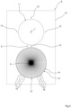
- Figure 3 shows a schematic view on an enlarged scale of the contrasting roller 12.
- a plurality of hollow portions 16 are provided, aligned along a transversal direction with respect to the machine direction MD, arranged to carry out the required pre-incision.
- the hollow portions 16 are circular in shape.
- the position of the hollow portions 16 varies from one section with grooves 14 to another, so that it does not come into contact with the cutting element 13 in the same way, so as to limit and make the wear of the cutting element 13 uniform.
- the rows of hollow portions 16 of the sections 14 are mutually misaligned along the axial direction of the sections 14. There is, therefore, a shift in position of the rows of hollow portions 16 between the sections 14 of the roller 12. This position deviation of the hollow portions 16 may be achieved in the order of 1-10 mm, according to different configurations.
- the position deviation is constant and progressive for a given number of sections 14.
- a succession of n sections 14 may have a progressive deviation of about 1 mm.
- a second succession of n sections 14 shows the same arrangement of hollow portions 16 as the previous succession.
- the Figure shows a reference line P configured for indicating the constant and progressive deviation of the hollow portions 16 for a succession of five sections with hollows 14.
- this constant and progressive deviation of the hollow portions 16, which in this exemplifying case refers to a succession of five sections with grooves 14, is to be understood as defined by the distance between the centers of the further reference lines parallel to the reference line P.
- the deviation in position of the slots 16 between the sections 14 can be increasing from one section 14 to another (for example, from a first to a second section, deviation of 1 mm, and from the second section to a third section deviation of 2 mm).
- the position deviation of the hollow portions 16 between the sections 14 may be achieved differently from what has been described above, provided that it is suitable for achieving the intended objects, i.e. creating the pre-incision effectively and limiting the wear of the cutting edges 13.
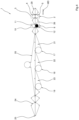
- Figure 4 illustrates a schematic side view of a preferred embodiment of an apparatus according to the present invention.
- the apparatus 1 is configured to carry out an automatic sorting of the packages C produced.
- the apparatus 1 has a plurality of conveyor means 20, 21, 22, 23 configured for automatically transporting the strips of consecutive pre-engraved uncut packages C automatically towards respective evacuation points 17, 18, 19.
- the apparatus 1 has at least three evacuation points 17, 18, 19 of the strips of packages C by means of the automatic activation of vacuum areas, to automatically sort the packages C towards certain collection points.
- These vacuum areas are made by vacuum conveyors of known type.
- the function of the conveyors 20, 21, 22, 23 is to positively guide the strips of packages C towards the evacuation points 17, 18, 19 (for example, within a collection box accessible from the outside or onto a further belt to carry the packages C out of the overall dimensions of the apparatus 1, for subsequent collection and bagging).
- the conveyors 20, 21, 22, 23 may be alternatively activated, according to a predetermined cycle by means of a command signal sent by the control device E, to allow n strips of packages C of m products to be respectively transported towards a given evacuation point 17, 18, 19.
- the conveyor means 20, 21, 22, 23 may comprise a plurality of lower belts 21,22,23, and an upper belt 20 configured for gripping the package portions C between their respective mutually facing surfaces.
- the upper belt 20 has a length substantially corresponding to that of the lower belts 21,22,23 in succession.
- Each lower belt 21,22,23 is arranged to guide the strips of products towards a respective evacuation point 17, 18, 19.
- the conveyors 20, 21, 22, 23 may comprise preferably sub-atmospheric pressure gripping means comprising a source of sub-atmospheric pressure.
- the apparatus 1 comprises further transport means 24 arranged at the end of the line with respect to the evacuation points 17, 18, 19, to transport the separate cut packages C beyond the aforesaid evacuation points 17, 18, 19 in an end-of-line point 25 for picking up (for example, for the bagging of packages of larger dimensions).
- the apparatus 1 is arranged to carry out a differentiated automatic sorting of both the individual separate packages C and the strips of pre-engraved packages C.
Landscapes
- Engineering & Computer Science (AREA)
- Mechanical Engineering (AREA)
- Life Sciences & Earth Sciences (AREA)
- Forests & Forestry (AREA)
- Containers And Plastic Fillers For Packaging (AREA)
- Auxiliary Devices For And Details Of Packaging Control (AREA)
Abstract
- a cutting roller (11) carrying at least one cutting element (13) configured to perform both a cutting operation to separate two consecutive articles, and an engraving between two consecutive articles without separating the articles,
- a contrasting roller (12) acting as a cutting surface, wherein a plurality of sections with grooves (14) are formed alternating with a plurality of solid sections (15), configured for providing segments of consecutive articles of desired length, with engravings between one article and another,
- a control device (E) configured to vary the phase between said cutting roller (11) and said contrasting roller (12).
A method for cutting a continuous chain of articles, using such a transversal cutting unit and automatically varying the phase between said cutting roller (11) and said contrasting roller (12), so as to produce segments of consecutive articles of desired length having engravings between one article and another.
Description
- The present invention relates in general to the packaging sector and specifically concerns flow-pack packaging.
- More precisely, the invention relates to a transversal cutting unit which can be used for the packaging of sanitary-absorbent articles, such as for example diapers, diaper-panties, feminine sanitary towels, etc.
- Flow-pack packaging is one of the most popular systems for packaging a large variety of consumer products.
- In flow-pack packaging systems, a continuous packaging film, typically of plastic material, is unwound from a reel and is folded into the shape of a continuous tubular member that surrounds the products to be packaged and advances in a machine direction together with the flow of products to be packaged. The continuous tubular member of packaging material is closed by means of a continuous longitudinal seal that joins the opposite longitudinal edges of the packaging film and by means of transverse seals spaced apart from each other in the machine direction that seal the continuous tubular member at opposite sides with respect to the products that must be included in a single package.
- A flow-pack packaging machine typically comprises:
- a horizontal conveyor configured to advance a flow of products along a longitudinal direction,
- an unwinding unit configured to feed a continuous packaging film,
- a stationary forming device configured to fold the packaging film in the form of a tubular element that surrounds the products to be packaged,
- a longitudinal welding assembly located downstream of the forming device and configured to weld together opposite longitudinal edges of the packaging film,
- a transverse welding assembly configured for transversally welding the tubular element formed by the film of packaging material, and
- a cutting element to separate the products.
- In accordance with a per se known technique, the packaging of absorbent sanitary articles, such as, for example, diapers, is achieved by wrapping the folded articles in a continuous film generally of polyethylene, by means of a suitable folding nozzle. The individual articles are transported in a machine direction within the continuous film that surrounds them. In the known solution, a welding station is arranged to seal the ends of the single package being created and, at the same time, a blade integrated in the same welding station separates the individual packages from each other. In a subsequent step of the method, the single package is carried to the step that is useful for multi-product packaging in larger bags.
- Known solutions envisage that the packaging machine is configured to produce strips of single packages, each including one or more products, wherein the individual packages are connected to each other and pre-engraved along the transverse sealing, to facilitate subsequent detachment of the single package.
- The present invention starts from the desire to make a cutting unit, an apparatus, and a relative method, arranged to make both a plurality of individually separated packages, and continuous and pre-engraved strips of individual packages, with the possibility of carrying out an automatic separation of the packages every n articles, where n varies according to production requirements.
- The object of the present invention is to provide a device that satisfies the requirements indicated above.
- According to the present invention, this object is achieved, by a cutting machine, an apparatus and a method having the characteristics forming the subject of
claims - The claims form an integral part of the disclosure provided here in relation to the invention.
- The present invention will now be described in detail with reference to the attached drawings, given purely by way of non-limiting example, wherein:
-
Figure 1 is a schematic side view of a flow-pack packaging apparatus according to the present invention, -
Figure 2 is a cross-sectional view of a cutting unit according to a preferred embodiment, -
Figure 3 is a plan view of a some details of the previous Figure, and -
Figure 4 is a schematic side view of an apparatus according to the invention, wherein additional operational operating steps are shown. - With reference to
Figures 1 ,4 , numeral 1 indicates a packaging apparatus of the horizontal flow-pack type. - In a packaging apparatus intended to form packages of the type currently referred to as "flow-pack", a conveyor is configured to advance a flow of articles to be packaged along a machine direction MD. In accordance with a preferred embodiment, the apparatus 1 is arranged to advance the articles along a substantially horizontal direction.
- In one or more embodiments, the apparatus 1 is arranged to package a flow of absorbent sanitary articles, such as for example diapers, diaper-panties, feminine sanitary towels, etc.
- The packages C are formed by arranging a continuous flow of articles fed to an inlet end of the apparatus 1 and by a continuous packaging film fed by an unwinding assembly of any known type.
- According to widely known criteria, starting from the continuous film, a continuous envelope T of substantially tubular shape is formed, which surrounds the articles to be packaged, by means of a forming device configured to fold the continuous packaging film.
- The continuous envelope T is advanced towards a longitudinal sealing station whose function is essentially to seal the longitudinal edges of the continuous envelope between two consecutive articles. According to a solution known per se, the sealing station may comprise a glue applicator designed to apply a layer of adhesive material along the longitudinal edges of the envelope T to be sealed.
-
Figure 1 illustrates a preferred embodiment of an apparatus 1 according to the invention. InFigure 1 , the articles are transported along the machine direction MD from right to left.Figure 1 does not show the details relating to the unwinding assembly, the forming device and the longitudinal sealing station, as these details may be made according to the prior art. - In accordance with a further characteristic of the invention, the continuous tubular envelope T is advanced by means of automated transport means 29 towards a
transversal welding unit 2 whose function is essentially to flatten the continuous envelope T in the spaces comprised between two consecutive articles, forming welding areas S in these spaces intended to hermetically separate the articles constituting a single package. - As illustrated in
Figure 4 , thetransversal welding station 2 may be composed of asupport structure 3 where a pair of counter-rotating rollers is installed, in particular, awelding roller 4 and acontrasting roller 5. Therollers - In one or more embodiments, the welding action is achieved with the combined application of pressure and heat. To this end, both the
rollers - In one or more embodiments, as in the one illustrated in
Figure 1 , thetransversal welding unit 2 comprises afirst welding element 6 and a second welding element 7 movable with respect to each other according to a second straight direction perpendicular to the first machine direction MD, between an open position and a closed position. Thewelding elements 6,7 may be configured to carry out ultrasonic welding. - According to the invention, the apparatus 1 comprises a
transversal cutting unit 8 that is separate and arranged downstream of thewelding unit 2, with reference to the machine direction MD. - As illustrated in
Figures 1 ,2 ,4 , thecutting unit 8 comprises a pair of activerotary elements 9 positioned at a respective side of the continuous envelope T, and configured to rotate around a respective axis I, II. In accordance with the example of horizontal packaging apparatus 1, the rotary elements are respectively positioned above and below the continuous envelope T. - In one or more embodiments, the
transversal cutting unit 8 may comprise asupport structure 10 on which the pair of activerotary elements 9 are mounted. - The pair of
active rotary elements 9 essentially consists of a cutting roller 11 (or knife) and a contrasting roller 12 (or counter-knife) driven in rotation by motor means (not shown). -
Figure 2 is a schematic view on an enlarged scale illustrating a preferred embodiment of thetransversal cutting unit 8. In accordance with the illustrated embodiment, the first rotary element (cutting roller 11) carries at least onecutting element 13 on its surface, to perform a cutting operation at a welded area S of the continuous envelope T, which advances along thewelding unit 2 andcutting unit 8. Preferably, thecutting roller 11 has fourcutting elements 13 spaced at 90° along the circumference of thecutting roller 11. - Again with reference to
Figure 2 , the second active rotary element (contrasting roller 12), which acts as a contact surface for the cut, has a plurality of sections withgrooves 14, alternating with a plurality ofsolid sections 15. As is evident from the following description and from the attached drawings, each section withgrooves 14 has a plurality ofhollow portions 16, each shaped so as to create a groove with respect to the continuous outer surface of theroller 12, while eachsolid section 15 has a regular continuous outer contact surface for cutting. Thecontrasting roller 12 may be made as a monolithic body with integratedhollow portions 16. - It should be noted that the sections with grooves and
solid sections contrasting roller 12. Therefore, during operation, eachcutting element 13 cooperates with thecontrasting roller 12 on a corresponding section with grooves orsolid section - Thanks to the characteristics indicated above, during operation, when a
cutting element 16 acts on a solid area - solid section 15 - a clean cut is made between two consecutive articles, thus separating the packages C. Conversely, when acutting element 16 acts on a region with grooves - section with grooves 14 - an engraving is made between two consecutive articles, without separating the articles, so as to create a segment of a plurality of consecutive articles. A transversal engraving is therefore formed between two consecutive articles, designed to favor a subsequent separation of the articles. The segments may thus be made of a certain desired length (a certain number of consecutive engraved articles). Note that the expression "desired length" means that it is possible to make batches of segments of articles of one length and batches of segments of another length different from the previous one, for example, groups of segments of three articles and groups of segments of five articles. - As previously indicated, the
rollers - In accordance with an additional characteristic of the invention, the apparatus 1 comprises an electronic control device E (illustrated in
Figure 1 ) programmed to vary the phase between the cuttingroller 11 and the contrastingroller 12. The expression "vary the phase" means a variation of the relative angular position between a cuttingelement 13 and a section with grooves/solid sections element 13 occurs with asolid section 15 and the contact of said cuttingelement 13 with a section withgrooves 14, so as to vary pre-incision cuts and clean cuts of the continuous envelope T that wraps the articles, in a variable way according to the production requirements. In one or more embodiments, the control device E is programmed to automatically control the contrastingroller 12 in acceleration or deceleration with respect to the cuttingroller 11, so as to vary the length of the segments of consecutive articles with engravings between one article and another. Thanks to these characteristics, article segments may be made of variable lengths without interrupting the production process. It should be noted thatFigure 1 illustrates an operating step of operation wherein the cutting unit is controlled to produce a plurality of articles with cut and separated packages C. - For correct operation, the cutting
roller 11 must have a peripheral speed substantially equal to the feed speed of the continuous envelope T. The contrastingroller 12 will, instead, have a variable peripheral speed, substantially corresponding to a multiple integer of the pitch between the alternatingsections cutting unit 8, to achieve the separation of the packages C or the continuous strip of pre-engraved packages C. - The description and attached drawings refer to a
transversal cutting unit 8, and to a related apparatus 1, arranged to cut/engrave the continuous envelope T including a plurality of articles mutually spaced apart at a constant pitch. However, it should be noted that the invention is equally applicable for cutting/engraving applied directly to a continuous chain of articles still without any packaging envelope. - More generally, in the context of the overall apparatus 1, the electronic control device E is, furthermore, configured to synchronize the operation of the
transversal welding unit 2 and of thecutting unit 8, so as to carry out the welding and the cutting (or pre-incision) of packages C in a single apparatus 1. In this regard, in one or more embodiments, as in the one illustrated inFigure 1 , astabilization unit 26 of the packages C is interposed between saidwelding unit 2 and said cuttingunit 8, comprising: - a
lower conveyor element 27 of continuous motorized loop type, having an active branch for conveying the packages C substantially aligned with the direction MD of the transit movement of the packages C, and - a motorized
upper conveyor element 28 having an active branch in contact with the transiting packages C. - In one or more embodiments, the operation of the forming of the packages C is continuous, as the envelope T may undergo variations in speed, but it never stops during operation to carry out the welding and cutting operations.
- In a preferred embodiment, the
transversal cutting unit 8 hasrollers rollers element 13 into contact with a section withgrooves 14 or with asolid section 15, respectively, to carry out the pre-incision without separating the articles or the cut of the envelope E with separation. - As previously indicated, the alternating grooves and
solid sections roller 12. -
Figure 3 shows a schematic view on an enlarged scale of the contrastingroller 12. For each section withgrooves 14, a plurality ofhollow portions 16 are provided, aligned along a transversal direction with respect to the machine direction MD, arranged to carry out the required pre-incision. Preferably, thehollow portions 16 are circular in shape. - In accordance with another preferred characteristic of the invention, the position of the
hollow portions 16 varies from one section withgrooves 14 to another, so that it does not come into contact with the cuttingelement 13 in the same way, so as to limit and make the wear of the cuttingelement 13 uniform. With reference to the embodiment illustrated in the plan view ofFigure 3 , it should be noted that the rows ofhollow portions 16 of thesections 14 are mutually misaligned along the axial direction of thesections 14. There is, therefore, a shift in position of the rows ofhollow portions 16 between thesections 14 of theroller 12. This position deviation of thehollow portions 16 may be achieved in the order of 1-10 mm, according to different configurations. - In the configuration shown in
Figure 3 , the position deviation is constant and progressive for a given number ofsections 14. For example, a succession ofn sections 14 may have a progressive deviation of about 1 mm. In other words, from a first to asecond section 14 there is a deviation of 1 mm, and from thesecond section 14 to thethird section 14 there is a further deviation of 1 mm. At the end of a first succession ofn sections 14 with constant and progressive deviation, a second succession ofn sections 14 shows the same arrangement ofhollow portions 16 as the previous succession. In this regard, by way of example, the Figure shows a reference line P configured for indicating the constant and progressive deviation of thehollow portions 16 for a succession of five sections withhollows 14. InFigure 3 , this constant and progressive deviation of thehollow portions 16, which in this exemplifying case refers to a succession of five sections withgrooves 14, is to be understood as defined by the distance between the centers of the further reference lines parallel to the reference line P. - According to a further configuration not shown, considering a succession of
n sections 14, the deviation in position of theslots 16 between thesections 14 can be increasing from onesection 14 to another (for example, from a first to a second section, deviation of 1 mm, and from the second section to a third section deviation of 2 mm). - Of course, the position deviation of the
hollow portions 16 between thesections 14 may be achieved differently from what has been described above, provided that it is suitable for achieving the intended objects, i.e. creating the pre-incision effectively and limiting the wear of the cutting edges 13. -
Figure 4 illustrates a schematic side view of a preferred embodiment of an apparatus according to the present invention. According to a further characteristic of the invention, the apparatus 1 is configured to carry out an automatic sorting of the packages C produced. - In one or more embodiments, the apparatus 1 has a plurality of conveyor means 20, 21, 22, 23 configured for automatically transporting the strips of consecutive pre-engraved uncut packages C automatically towards respective evacuation points 17, 18, 19. Preferably, the apparatus 1 has at least three
evacuation points - The function of the
conveyors conveyors evacuation point - The conveyor means 20, 21, 22, 23 may comprise a plurality of
lower belts upper belt 20 configured for gripping the package portions C between their respective mutually facing surfaces. Theupper belt 20 has a length substantially corresponding to that of thelower belts lower belt respective evacuation point conveyors - In one or more embodiments, such as in the one illustrated in
Figure 4 , the apparatus 1 comprises further transport means 24 arranged at the end of the line with respect to the evacuation points 17, 18, 19, to transport the separate cut packages C beyond the aforesaid evacuation points 17, 18, 19 in an end-of-line point 25 for picking up (for example, for the bagging of packages of larger dimensions). - Thanks to these characteristics, the apparatus 1 is arranged to carry out a differentiated automatic sorting of both the individual separate packages C and the strips of pre-engraved packages C.
- Of course, without prejudice to the principle of the invention, the details of construction and the embodiments may vary widely with respect to those described and illustrated purely by way of example, without departing from the scope of the present invention.
Claims (10)
- A transversal cutting unit (8) for obtaining segments of consecutive articles of desired length, having engravings between one article and another of the same segment of consecutive articles, comprising:- a cutting roller (11) carrying at least one cutting element (13) configured to perform both a cutting operation to separate two consecutive articles, and an engraving between two consecutive articles without separating the articles,- a contrasting roller (12) acting as a cutting surface, wherein a plurality of sections with grooves (14) are formed alternating with a plurality of solid sections (15), configured for providing segments of consecutive articles of desired length, with engravings between one article and another,- a control device (E) configured to vary the phase between said cutting roller (11) and said contrasting roller (12).
- A unit (8) according to claim 1, wherein said control device (E) is configured to accelerate the contrasting roller (12) with respect to the cutting roller (11).
- A unit (8) according to any one of the previous claims, wherein said control device (E) is configured to decelerate the contrasting roller (12) with respect to the cutting roller (11).
- A unit (8) according to any one of the previous claims, wherein said solid sections (15) and said sections with grooves (14) are alternated with constant pitch along the circumference of the contrasting roller (12) .
- A packaging apparatus (1) comprising at least one transversal cutting unit (8) according to any of claims 1-4.
- An apparatus (1) according to claim 5, comprising:- a forming device configured to fold a packaging film in the form of a continuous envelope (T) surrounding a chain of articles,- a transversal welding unit (2) separated and arranged upstream with respect to said transversal cutting unit (8), wherein the welding unit (2) is configured for transversely welding the continuous envelope (T) and the cutting unit (8) is configured for cutting or engraving a welded area (S) of the continuous envelope (T), wherein the electronic control device (E) is configured to synchronize the operations of the welding unit (2) and the cutting unit (8).
- An apparatus (1) according to any one of claims 5,6, comprising:- a plurality of conveyor means (20, 21, 22, 23) provided for automatically transporting segments of articles automatically engraved to different evacuation points (17, 18, 19),- wherein said conveyor means (20, 21, 22, 23) include gripping means preferably with sub-atmospheric pressure, alternatively actuated to direct a predetermined number of segments for each evacuation point (17, 18, 19).
- A method for cutting a continuous chain of articles, comprising the following steps:- feeding a chain of articles along a machine direction (MD),- providing a transversal cutting unit (8) as claimed according to any of claims 1-4,- automatically varying the phase between said cutting roller (11) and said contrasting roller (12), so as to produce segments of consecutive articles of desired length having engravings between one article and another.
- A method according to claim 8, comprising the step of accelerating the contrasting roller (12) with respect to the cutting roller (11).
- A method according to claim 8 or 9, comprising the step of decelerating the contrasting roller (12) with respect to the cutting roller (11).
Applications Claiming Priority (1)
| Application Number | Priority Date | Filing Date | Title |
|---|---|---|---|
| IT202200004127 | 2022-03-04 |
Publications (3)
| Publication Number | Publication Date |
|---|---|
| EP4238728A1 true EP4238728A1 (en) | 2023-09-06 |
| EP4238728B1 EP4238728B1 (en) | 2024-11-27 |
| EP4238728C0 EP4238728C0 (en) | 2024-11-27 |
Family
ID=81749215
Family Applications (1)
| Application Number | Title | Priority Date | Filing Date |
|---|---|---|---|
| EP23159598.4A Active EP4238728B1 (en) | 2022-03-04 | 2023-03-02 | A unit, apparatus and method for cutting a chain of articles |
Country Status (5)
| Country | Link |
|---|---|
| US (1) | US12065278B2 (en) |
| EP (1) | EP4238728B1 (en) |
| JP (1) | JP7529190B2 (en) |
| ES (1) | ES2992344T3 (en) |
| PL (1) | PL4238728T3 (en) |
Families Citing this family (3)
| Publication number | Priority date | Publication date | Assignee | Title |
|---|---|---|---|---|
| IT202000019414A1 (en) * | 2020-08-06 | 2022-02-06 | Tecno Pack S P A | HORIZONTAL PACKAGING MACHINE WITH ADJUSTABLE CUTTING-OVERCUT GROUP |
| EP4624348A1 (en) * | 2024-03-27 | 2025-10-01 | Centrum Badan i Rozwoju Technologii dla Przemyslu S.A. | A system and method for packaging a stream of items |
| CN118808291B (en) * | 2024-09-18 | 2024-12-24 | 四川菊乐食品股份有限公司 | Pressure device for secondary recovery of liquid packaging box |
Citations (4)
| Publication number | Priority date | Publication date | Assignee | Title |
|---|---|---|---|---|
| US6050927A (en) * | 1997-05-29 | 2000-04-18 | Moore U.S.A., Inc. | On-demand skip perforating |
| WO2013038310A1 (en) * | 2011-09-12 | 2013-03-21 | Fameccanica.Data S.P.A. | A method for automatic packaging of sanitary articles, and corresponding system |
| US20190161312A1 (en) * | 2017-11-30 | 2019-05-30 | Müller Martini Holding AG | Apparatus and method for cutting or perforating a paper web |
| IT201900015650A1 (en) * | 2019-09-05 | 2021-03-05 | Sidel Participations Sas | DEVICE TO SEPARATE LABELS FROM A STRIP OF LABELING MATERIAL AND METHOD FOR APPLYING LABELS TO ITEMS |
Family Cites Families (13)
| Publication number | Priority date | Publication date | Assignee | Title |
|---|---|---|---|---|
| JPS6112324Y2 (en) * | 1979-03-14 | 1986-04-17 | ||
| JP3241188B2 (en) * | 1993-09-21 | 2001-12-25 | 三菱重工業株式会社 | Signature making method and apparatus |
| FR2781778B1 (en) | 1998-08-03 | 2000-10-13 | Heidelberger Druckmasch Ag | IMPROVED CUTTING DEVICE FOR A WEB OF MATERIAL IN A BENDING MACHINE OF A PRINTING ROTARY, AND STITCHING FOLDER COMPRISING SUCH A DEVICE |
| US6418828B1 (en) | 1999-06-24 | 2002-07-16 | The Procter & Gamble Company | Force-adjustable rotary apparatus for working webs or sheets of material |
| JP4101686B2 (en) | 2003-03-28 | 2008-06-18 | 三菱重工業株式会社 | Cut-off device |
| JP4187589B2 (en) | 2003-06-04 | 2008-11-26 | 三光機械株式会社 | Rotary cutter for automatic packaging machine |
| JP4518842B2 (en) | 2004-05-31 | 2010-08-04 | 花王株式会社 | Sheet cutting device |
| JP2006240680A (en) | 2005-03-03 | 2006-09-14 | Sanko Kikai Kk | Cutter device for rotary automatic packaging machine |
| JP4601589B2 (en) | 2006-08-18 | 2010-12-22 | 味日本株式会社 | Rotary cutter unit and filling and packaging device |
| JP5224503B2 (en) | 2006-10-02 | 2013-07-03 | 株式会社悠心 | Tear-induced wrinkle forming roll pair and packaging machine for packaging bags |
| JP2008189567A (en) | 2007-02-01 | 2008-08-21 | Nippon Tenganyaku Kenkyusho:Kk | Prostaglandin aqueous eye drops |
| JP5617072B2 (en) | 2010-09-24 | 2014-11-05 | ケイディケイ株式会社 | Information communication body cut position adjusting means |
| WO2018025917A1 (en) | 2016-08-03 | 2018-02-08 | 株式会社フューチャーラボ | Fold-open package and method for manufacturing fold-open package |
-
2023
- 2023-02-28 JP JP2023029989A patent/JP7529190B2/en active Active
- 2023-03-02 PL PL23159598.4T patent/PL4238728T3/en unknown
- 2023-03-02 US US18/177,664 patent/US12065278B2/en active Active
- 2023-03-02 ES ES23159598T patent/ES2992344T3/en active Active
- 2023-03-02 EP EP23159598.4A patent/EP4238728B1/en active Active
Patent Citations (4)
| Publication number | Priority date | Publication date | Assignee | Title |
|---|---|---|---|---|
| US6050927A (en) * | 1997-05-29 | 2000-04-18 | Moore U.S.A., Inc. | On-demand skip perforating |
| WO2013038310A1 (en) * | 2011-09-12 | 2013-03-21 | Fameccanica.Data S.P.A. | A method for automatic packaging of sanitary articles, and corresponding system |
| US20190161312A1 (en) * | 2017-11-30 | 2019-05-30 | Müller Martini Holding AG | Apparatus and method for cutting or perforating a paper web |
| IT201900015650A1 (en) * | 2019-09-05 | 2021-03-05 | Sidel Participations Sas | DEVICE TO SEPARATE LABELS FROM A STRIP OF LABELING MATERIAL AND METHOD FOR APPLYING LABELS TO ITEMS |
Also Published As
| Publication number | Publication date |
|---|---|
| JP7529190B2 (en) | 2024-08-06 |
| US20230278743A1 (en) | 2023-09-07 |
| EP4238728B1 (en) | 2024-11-27 |
| ES2992344T3 (en) | 2024-12-11 |
| EP4238728C0 (en) | 2024-11-27 |
| JP2023129330A (en) | 2023-09-14 |
| PL4238728T3 (en) | 2025-02-24 |
| US12065278B2 (en) | 2024-08-20 |
Similar Documents
| Publication | Publication Date | Title |
|---|---|---|
| US12065278B2 (en) | Unit, apparatus and method for cutting a chain of article | |
| US4385479A (en) | Apparatus for the preparation of packaging blanks by severing from a continuous web | |
| US4347934A (en) | Corrugated container | |
| US3890763A (en) | Packaging machine and method | |
| KR100241080B1 (en) | Method and apparatus for forming a slice of a food item having a heat tack seal | |
| EP1818264B1 (en) | A method and line for the high-speed packaging of filter bags containing an infusion product. | |
| GB1578973A (en) | Wrapping method and apparatus | |
| US10189595B2 (en) | Feeding unit for feeding sealed packs of pourable food products | |
| EP2143555B1 (en) | Machine for producing packaging material in the form of cushions filled with air or other gas | |
| US5269122A (en) | Apparatus and method for forming protective packages | |
| US5466474A (en) | Method and apparatus for manufacturing infusion packages | |
| EP3009359B1 (en) | Feeding unit for feeding sealed packs of pourable food products | |
| US10087008B2 (en) | Feeding unit for feeding sealed packs of pourable food products | |
| AU2003262105B2 (en) | Method and device for the packaging of flat objects | |
| GB2214128A (en) | An automatic sealing method | |
| US3954367A (en) | Stacking wheels with superimposed retarder action | |
| EP1413521B1 (en) | Horizontal packaging machine for making fluid-tight packages equipped with zip closure | |
| US4395253A (en) | Method of making corrugated packages | |
| EP0142904A2 (en) | A method and device for wrap packaging of articles | |
| EP0844070A1 (en) | Method and apparatus for obtaining individual web sections | |
| AU4015995A (en) | Packaging apparatus and method for preventing separation of package seals | |
| CN1073147A (en) | Method and apparatus to the part of a wrapping machine conveying and packaging material | |
| SU1627419A1 (en) | Method and apparatus for making fly tape-type products |
Legal Events
| Date | Code | Title | Description |
|---|---|---|---|
| PUAI | Public reference made under article 153(3) epc to a published international application that has entered the european phase |
Free format text: ORIGINAL CODE: 0009012 |
|
| STAA | Information on the status of an ep patent application or granted ep patent |
Free format text: STATUS: THE APPLICATION HAS BEEN PUBLISHED |
|
| AK | Designated contracting states |
Kind code of ref document: A1 Designated state(s): AL AT BE BG CH CY CZ DE DK EE ES FI FR GB GR HR HU IE IS IT LI LT LU LV MC ME MK MT NL NO PL PT RO RS SE SI SK SM TR |
|
| STAA | Information on the status of an ep patent application or granted ep patent |
Free format text: STATUS: REQUEST FOR EXAMINATION WAS MADE |
|
| 17P | Request for examination filed |
Effective date: 20240117 |
|
| RBV | Designated contracting states (corrected) |
Designated state(s): AL AT BE BG CH CY CZ DE DK EE ES FI FR GB GR HR HU IE IS IT LI LT LU LV MC ME MK MT NL NO PL PT RO RS SE SI SK SM TR |
|
| GRAP | Despatch of communication of intention to grant a patent |
Free format text: ORIGINAL CODE: EPIDOSNIGR1 |
|
| STAA | Information on the status of an ep patent application or granted ep patent |
Free format text: STATUS: GRANT OF PATENT IS INTENDED |
|
| INTG | Intention to grant announced |
Effective date: 20240715 |
|
| GRAS | Grant fee paid |
Free format text: ORIGINAL CODE: EPIDOSNIGR3 |
|
| GRAA | (expected) grant |
Free format text: ORIGINAL CODE: 0009210 |
|
| STAA | Information on the status of an ep patent application or granted ep patent |
Free format text: STATUS: THE PATENT HAS BEEN GRANTED |
|
| AK | Designated contracting states |
Kind code of ref document: B1 Designated state(s): AL AT BE BG CH CY CZ DE DK EE ES FI FR GB GR HR HU IE IS IT LI LT LU LV MC ME MK MT NL NO PL PT RO RS SE SI SK SM TR |
|
| REG | Reference to a national code |
Ref country code: GB Ref legal event code: FG4D |
|
| REG | Reference to a national code |
Ref country code: CH Ref legal event code: EP |
|
| REG | Reference to a national code |
Ref country code: ES Ref legal event code: FG2A Ref document number: 2992344 Country of ref document: ES Kind code of ref document: T3 Effective date: 20241211 |
|
| REG | Reference to a national code |
Ref country code: IE Ref legal event code: FG4D |
|
| REG | Reference to a national code |
Ref country code: DE Ref legal event code: R096 Ref document number: 602023001130 Country of ref document: DE |
|
| U01 | Request for unitary effect filed |
Effective date: 20241203 |
|
| U07 | Unitary effect registered |
Designated state(s): AT BE BG DE DK EE FI FR IT LT LU LV MT NL PT RO SE SI Effective date: 20241212 |
|
| PG25 | Lapsed in a contracting state [announced via postgrant information from national office to epo] |
Ref country code: IS Free format text: LAPSE BECAUSE OF FAILURE TO SUBMIT A TRANSLATION OF THE DESCRIPTION OR TO PAY THE FEE WITHIN THE PRESCRIBED TIME-LIMIT Effective date: 20250327 Ref country code: HR Free format text: LAPSE BECAUSE OF FAILURE TO SUBMIT A TRANSLATION OF THE DESCRIPTION OR TO PAY THE FEE WITHIN THE PRESCRIBED TIME-LIMIT Effective date: 20241127 |
|
| PG25 | Lapsed in a contracting state [announced via postgrant information from national office to epo] |
Ref country code: NO Free format text: LAPSE BECAUSE OF FAILURE TO SUBMIT A TRANSLATION OF THE DESCRIPTION OR TO PAY THE FEE WITHIN THE PRESCRIBED TIME-LIMIT Effective date: 20250227 |
|
| PG25 | Lapsed in a contracting state [announced via postgrant information from national office to epo] |
Ref country code: GR Free format text: LAPSE BECAUSE OF FAILURE TO SUBMIT A TRANSLATION OF THE DESCRIPTION OR TO PAY THE FEE WITHIN THE PRESCRIBED TIME-LIMIT Effective date: 20250228 |
|
| PG25 | Lapsed in a contracting state [announced via postgrant information from national office to epo] |
Ref country code: RS Free format text: LAPSE BECAUSE OF FAILURE TO SUBMIT A TRANSLATION OF THE DESCRIPTION OR TO PAY THE FEE WITHIN THE PRESCRIBED TIME-LIMIT Effective date: 20250227 |
|
| U20 | Renewal fee for the european patent with unitary effect paid |
Year of fee payment: 3 Effective date: 20250327 |
|
| PG25 | Lapsed in a contracting state [announced via postgrant information from national office to epo] |
Ref country code: SM Free format text: LAPSE BECAUSE OF FAILURE TO SUBMIT A TRANSLATION OF THE DESCRIPTION OR TO PAY THE FEE WITHIN THE PRESCRIBED TIME-LIMIT Effective date: 20241127 |
|
| PGFP | Annual fee paid to national office [announced via postgrant information from national office to epo] |
Ref country code: ES Payment date: 20250401 Year of fee payment: 3 |
|
| PG25 | Lapsed in a contracting state [announced via postgrant information from national office to epo] |
Ref country code: SK Free format text: LAPSE BECAUSE OF FAILURE TO SUBMIT A TRANSLATION OF THE DESCRIPTION OR TO PAY THE FEE WITHIN THE PRESCRIBED TIME-LIMIT Effective date: 20241127 |
|
| PLBE | No opposition filed within time limit |
Free format text: ORIGINAL CODE: 0009261 |
|
| STAA | Information on the status of an ep patent application or granted ep patent |
Free format text: STATUS: NO OPPOSITION FILED WITHIN TIME LIMIT |
|
| PG25 | Lapsed in a contracting state [announced via postgrant information from national office to epo] |
Ref country code: MC Free format text: LAPSE BECAUSE OF FAILURE TO SUBMIT A TRANSLATION OF THE DESCRIPTION OR TO PAY THE FEE WITHIN THE PRESCRIBED TIME-LIMIT Effective date: 20241127 |
|
| 26N | No opposition filed |
Effective date: 20250828 |
|
| PG25 | Lapsed in a contracting state [announced via postgrant information from national office to epo] |
Ref country code: IE Free format text: LAPSE BECAUSE OF NON-PAYMENT OF DUE FEES Effective date: 20250302 |
|
| PGFP | Annual fee paid to national office [announced via postgrant information from national office to epo] |
Ref country code: TR Payment date: 20260220 Year of fee payment: 4 |
|
| PGFP | Annual fee paid to national office [announced via postgrant information from national office to epo] |
Ref country code: CZ Payment date: 20260224 Year of fee payment: 4 |
|
| PGFP | Annual fee paid to national office [announced via postgrant information from national office to epo] |
Ref country code: PL Payment date: 20260218 Year of fee payment: 4 |
|
| U20 | Renewal fee for the european patent with unitary effect paid |
Year of fee payment: 4 Effective date: 20260327 |