EP4238545A1 - Control box of massage pool and massage pool - Google Patents
Control box of massage pool and massage pool Download PDFInfo
- Publication number
- EP4238545A1 EP4238545A1 EP22159895.6A EP22159895A EP4238545A1 EP 4238545 A1 EP4238545 A1 EP 4238545A1 EP 22159895 A EP22159895 A EP 22159895A EP 4238545 A1 EP4238545 A1 EP 4238545A1
- Authority
- EP
- European Patent Office
- Prior art keywords
- massage
- pipe
- filtering
- valve
- control box
- Prior art date
- Legal status (The legal status is an assumption and is not a legal conclusion. Google has not performed a legal analysis and makes no representation as to the accuracy of the status listed.)
- Granted
Links
Images






Classifications
-
- A—HUMAN NECESSITIES
- A61—MEDICAL OR VETERINARY SCIENCE; HYGIENE
- A61H—PHYSICAL THERAPY APPARATUS, e.g. DEVICES FOR LOCATING OR STIMULATING REFLEX POINTS IN THE BODY; ARTIFICIAL RESPIRATION; MASSAGE; BATHING DEVICES FOR SPECIAL THERAPEUTIC OR HYGIENIC PURPOSES OR SPECIFIC PARTS OF THE BODY
- A61H33/00—Bathing devices for special therapeutic or hygienic purposes
- A61H33/60—Components specifically designed for the therapeutic baths of groups A61H33/00
- A61H33/601—Inlet to the bath
- A61H33/6021—Nozzles
-
- A—HUMAN NECESSITIES
- A61—MEDICAL OR VETERINARY SCIENCE; HYGIENE
- A61H—PHYSICAL THERAPY APPARATUS, e.g. DEVICES FOR LOCATING OR STIMULATING REFLEX POINTS IN THE BODY; ARTIFICIAL RESPIRATION; MASSAGE; BATHING DEVICES FOR SPECIAL THERAPEUTIC OR HYGIENIC PURPOSES OR SPECIFIC PARTS OF THE BODY
- A61H33/00—Bathing devices for special therapeutic or hygienic purposes
- A61H33/02—Bathing devices for use with gas-containing liquid, or liquid in which gas is led or generated, e.g. carbon dioxide baths
-
- A—HUMAN NECESSITIES
- A61—MEDICAL OR VETERINARY SCIENCE; HYGIENE
- A61H—PHYSICAL THERAPY APPARATUS, e.g. DEVICES FOR LOCATING OR STIMULATING REFLEX POINTS IN THE BODY; ARTIFICIAL RESPIRATION; MASSAGE; BATHING DEVICES FOR SPECIAL THERAPEUTIC OR HYGIENIC PURPOSES OR SPECIFIC PARTS OF THE BODY
- A61H33/00—Bathing devices for special therapeutic or hygienic purposes
-
- A—HUMAN NECESSITIES
- A61—MEDICAL OR VETERINARY SCIENCE; HYGIENE
- A61H—PHYSICAL THERAPY APPARATUS, e.g. DEVICES FOR LOCATING OR STIMULATING REFLEX POINTS IN THE BODY; ARTIFICIAL RESPIRATION; MASSAGE; BATHING DEVICES FOR SPECIAL THERAPEUTIC OR HYGIENIC PURPOSES OR SPECIFIC PARTS OF THE BODY
- A61H33/00—Bathing devices for special therapeutic or hygienic purposes
- A61H33/0087—Therapeutic baths with agitated or circulated water
-
- A—HUMAN NECESSITIES
- A61—MEDICAL OR VETERINARY SCIENCE; HYGIENE
- A61H—PHYSICAL THERAPY APPARATUS, e.g. DEVICES FOR LOCATING OR STIMULATING REFLEX POINTS IN THE BODY; ARTIFICIAL RESPIRATION; MASSAGE; BATHING DEVICES FOR SPECIAL THERAPEUTIC OR HYGIENIC PURPOSES OR SPECIFIC PARTS OF THE BODY
- A61H33/00—Bathing devices for special therapeutic or hygienic purposes
- A61H33/60—Components specifically designed for the therapeutic baths of groups A61H33/00
-
- A—HUMAN NECESSITIES
- A61—MEDICAL OR VETERINARY SCIENCE; HYGIENE
- A61H—PHYSICAL THERAPY APPARATUS, e.g. DEVICES FOR LOCATING OR STIMULATING REFLEX POINTS IN THE BODY; ARTIFICIAL RESPIRATION; MASSAGE; BATHING DEVICES FOR SPECIAL THERAPEUTIC OR HYGIENIC PURPOSES OR SPECIFIC PARTS OF THE BODY
- A61H33/00—Bathing devices for special therapeutic or hygienic purposes
- A61H33/60—Components specifically designed for the therapeutic baths of groups A61H33/00
- A61H33/6005—Special constructive structural details of the bathtub, e.g. of the walls or supporting structure
-
- E—FIXED CONSTRUCTIONS
- E04—BUILDING
- E04H—BUILDINGS OR LIKE STRUCTURES FOR PARTICULAR PURPOSES; SWIMMING OR SPLASH BATHS OR POOLS; MASTS; FENCING; TENTS OR CANOPIES, IN GENERAL
- E04H4/00—Swimming or splash baths or pools
- E04H4/14—Parts, details or accessories not otherwise provided for
-
- F—MECHANICAL ENGINEERING; LIGHTING; HEATING; WEAPONS; BLASTING
- F16—ENGINEERING ELEMENTS AND UNITS; GENERAL MEASURES FOR PRODUCING AND MAINTAINING EFFECTIVE FUNCTIONING OF MACHINES OR INSTALLATIONS; THERMAL INSULATION IN GENERAL
- F16L—PIPES; JOINTS OR FITTINGS FOR PIPES; SUPPORTS FOR PIPES, CABLES OR PROTECTIVE TUBING; MEANS FOR THERMAL INSULATION IN GENERAL
- F16L41/00—Branching pipes; Joining pipes to walls
- F16L41/02—Branch units, e.g. made in one piece, welded, riveted
-
- A—HUMAN NECESSITIES
- A61—MEDICAL OR VETERINARY SCIENCE; HYGIENE
- A61H—PHYSICAL THERAPY APPARATUS, e.g. DEVICES FOR LOCATING OR STIMULATING REFLEX POINTS IN THE BODY; ARTIFICIAL RESPIRATION; MASSAGE; BATHING DEVICES FOR SPECIAL THERAPEUTIC OR HYGIENIC PURPOSES OR SPECIFIC PARTS OF THE BODY
- A61H33/00—Bathing devices for special therapeutic or hygienic purposes
- A61H2033/0037—Arrangement for cleaning the fluid during use
-
- A—HUMAN NECESSITIES
- A61—MEDICAL OR VETERINARY SCIENCE; HYGIENE
- A61H—PHYSICAL THERAPY APPARATUS, e.g. DEVICES FOR LOCATING OR STIMULATING REFLEX POINTS IN THE BODY; ARTIFICIAL RESPIRATION; MASSAGE; BATHING DEVICES FOR SPECIAL THERAPEUTIC OR HYGIENIC PURPOSES OR SPECIFIC PARTS OF THE BODY
- A61H33/00—Bathing devices for special therapeutic or hygienic purposes
- A61H33/02—Bathing devices for use with gas-containing liquid, or liquid in which gas is led or generated, e.g. carbon dioxide baths
- A61H2033/022—Bathing devices for use with gas-containing liquid, or liquid in which gas is led or generated, e.g. carbon dioxide baths with control means for regulating the air volume aspirated by a water jet
-
- A—HUMAN NECESSITIES
- A61—MEDICAL OR VETERINARY SCIENCE; HYGIENE
- A61H—PHYSICAL THERAPY APPARATUS, e.g. DEVICES FOR LOCATING OR STIMULATING REFLEX POINTS IN THE BODY; ARTIFICIAL RESPIRATION; MASSAGE; BATHING DEVICES FOR SPECIAL THERAPEUTIC OR HYGIENIC PURPOSES OR SPECIFIC PARTS OF THE BODY
- A61H2201/00—Characteristics of apparatus not provided for in the preceding codes
- A61H2201/02—Characteristics of apparatus not provided for in the preceding codes heated or cooled
- A61H2201/0221—Mechanism for heating or cooling
- A61H2201/0228—Mechanism for heating or cooling heated by an electric resistance element
- A61H2201/0235—Thermistors with Positive Temperature Coefficient [PTC]
-
- A—HUMAN NECESSITIES
- A61—MEDICAL OR VETERINARY SCIENCE; HYGIENE
- A61H—PHYSICAL THERAPY APPARATUS, e.g. DEVICES FOR LOCATING OR STIMULATING REFLEX POINTS IN THE BODY; ARTIFICIAL RESPIRATION; MASSAGE; BATHING DEVICES FOR SPECIAL THERAPEUTIC OR HYGIENIC PURPOSES OR SPECIFIC PARTS OF THE BODY
- A61H33/00—Bathing devices for special therapeutic or hygienic purposes
- A61H33/0095—Arrangements for varying the temperature of the liquid
Definitions
- the present invention discloses apparatuses and methods consistent with example embodiments which relate to massage pools, and more specifically to a control box of a massage pool and a massage pool comprising the control box.
- a massage pool may be controlled by a control box used to implement any of various water circulation functions.
- the water circulation functions may include water filtering functions and water massage functions.
- a water conduit for filtration of water in a water circulation system may be independent from a water conduit for water in a water massage system.
- Example embodiments may address at least the above problems and/or disadvantages and other disadvantages not described above. Also, example embodiments are not required to overcome the disadvantages described above, and may not overcome any of the problems described above.
- One or more example embodiments may provide a control box of a massage pool and a massage pool comprising the control box.
- a control box of a massage pool comprises: a filtering pump unit comprising: a filtering pump body, a filtering water inlet pipe connected between the massage pool and the filtering pump body, and a filtering output pipe; a massage pump unit, the massage pump unit comprising: a massage pump body , a massage inlet pipe connected between the massage pool and the massage pump body, and a massage output pipe; a water outlet pipe configured to output water to the massage pool; a three-way connecting pipe fitting comprising: a first branch pipe having a distal end connected to the filtering output pipe, a second branch pipe having a distal end connected to the massage output pipe, and a third branch pipe having a distal end connected to the water outlet pipe; and at least one valve configured to alternately open and close a first flow path from the filtering output pipe through the first branch pipe.
- the at least one valve may be a first swing check one-way valve comprising a first pivot shaft, a first valve clack pivotable around the first pivot shaft, and a first valve seat.
- the at least one valve may be disposed in at least one of the filtering output pipe, the massage output pipe, and the three-way connecting pipe fitting; and the at least one valve may be configured to alternately open the first flow path and open a second flow path from the massage output pipe through the second branch pipe.
- the at least one valve may comprise: a first swing check one-way valve disposed at a connection between the filtering output pipe and the first branch pipe; and a second swing check one-way valve disposed at a connection between the massage output pipe and the second branch pipe.
- the first swing check one-way valve may be disposed at a connection between the filtering output pipe and the first branch pipe.
- the at least one valve may be a lift valve comprising: a valve stem, a valve clack capable of reciprocating along the valve stem, and a valve seat.
- a height at which the water outlet pipe is disposed may be greater than or equal to heights at which the filtering output pipe, the massage output pipe, and the three-way connecting pipe fitting are disposed.
- the control box may further comprise an air pump unit comprising an air pump body and an air pump output pipe, the air pump output pipe configured to be connected to an air inlet conduit of the massage pool.
- the control box may further comprise a heater connected to the filtering output pipe.
- a massage pool may be provided comprising the control box as described above.
- a control box of a massage pool comprising: a filtering pump unit comprising a filtering inlet pipe, a filtering pump body, and a filtering output pipe; a massage pump unit comprising a massage inlet pipe, a massage pump body, and a massage output pipe; a three-way connecting pipe fitting; a water outlet pipe; and at least one valve; wherein the three-way connecting pipe fitting comprises: a first branch pipe having a distal end connected to the filtering output pipe and a proximal end connected to a juncture of the three-way connecting pipe fitting; a second branch pipe having a distal end connected to the massage output pipe and a proximal end connected to the juncture; and a third branch pipe having a distal end connected to the water outlet pipe and a proximal end connected to the juncture; wherein the at least one valve is configured to alternately open and close a first flow path comprising the filtering output pipe,
- the term “and/or” includes any and all combinations of one or more of the associated listed items. Expressions such as “at least one of,” when preceding a list of elements, modify the entire list of elements and do not modify the individual elements of the list.
- the terms such as “unit,” “-er (-or),” and “module” described in the specification refer to an element for performing at least one function or operation, and may be implemented in hardware, software, or the combination of hardware and software.
- FIG. 1 illustrates a schematic diagram of a massage pool 100 and a control box 200 according to an example embodiment.
- the control box 200 is connected to the massage pool 100.
- One or more massage nozzles 102 are provided on an inner wall of the massage pool 100.
- an inlet flow direction and an outlet flow direction of water represented by "inlet” in “a filtering water inlet pipe” and “a massage water inlet pipe” and “outlet” in “a water outlet pipe” are described with respect to the control box. That is, a flow direction from the massage pool 100 to the control box is described as an "inlet” direction, and a flow direction from the control box 200 to the massage pool 100 is described as an "outlet” direction.
- a filtering water pump unit in the control box 200 operates, while a massage water pump unit in the control box does not operate.
- Water in the massage pool 100 flows from the massage pool 100 into a filtering water pump body 204 through a filtering water inlet pipe 206; is pumped by the filtering water pump body 204 to a filtering output pipe 208; and then flows back to the massage pool 100 via a water outlet pipe 230.
- a first flow path is defined as starting at an end of the filtering output pipe close to the filtering water pump body and ending at a connection between a first branch pipe and a second branch pipe or a third branch pipe.
- the massage water pump unit in the control box 200 When the control box 200 is set to a massage mode, the massage water pump unit in the control box 200 operates, and the filtering water pump unit in the control box does not operate.
- Water in the massage pool 100 flows from the massage pool 100 into a massage water pump body 214 through a massage water inlet pipe 216; is pumped by the massage water pump body 214 to a massage outlet pipe 218, then flows back to a water conduit provided in the massage pool 100 via the water outlet pipe 230; and is ejected from the massage nozzle 102.
- a water conduit path is defined as starting at an end of the massage output pipe, close to the massage water pump body, and ending at a connection between the second branch pipe and the third branch pipe.
- a valve may be provided inside the control box 200. The valve may be used for guiding a flow direction of water.
- FIG. 2 shows a filtering water pump unit, a massage water pump unit, a three-way connecting pipe fitting 220, a water outlet pipe 230, an air pump body 264, a positive temperature coefficient (PTC) heater 270, and other elements described below.
- the filtering water pump unit comprises: a filtering water inlet pipe 206, a filtering water pump body 204 connected to the filtering water inlet pipe 206, and a filtering output pipe 208 connected to the filtering water pump body 204.
- the filtering water inlet pipe 206 extends in a horizontal direction outside a housing of the control box.
- the massage water pump unit comprises: a massage water inlet pipe 216, a massage water pump body 214 connected to the massage water inlet pipe 216, and a massage output pipe 218 connected to the massage water pump body 214.
- the massage water inlet pipe 216 extends in the horizontal direction outside the housing of the control box.
- the three-way connecting pipe fitting 220 comprises: a first branch pipe 222 connected to the filtering output pipe 208; a second branch pipe 224 connected to the massage output pipe 218; and a third branch pipe 226 connected to the water outlet pipe 230.
- the first branch pipe 222 has a distal end connected to the filtering output pipe 208, and a proximal end connected to a juncture of the second branch pipe 224, where the third branch pipe 226 is connected to the second branch pipe 224.
- the second branch pipe 224 has a distal end connected to the massage output pipe 218, and a juncture at a proximal end, where the third branch pipe 226 and the first branch pipe 222 are connected to the second branch pipe 224.
- the third branch pipe 226 has a distal end connected to the water outlet pipe and a proximal end connected to the juncture in the second branch pipe 224. In the example embodiment shown in FIG.
- the first branch pipe 222 is staggered downward from the second branch pipe 224, and the third branch pipe 226 is connected to the second branch pipe 224.
- the water outlet pipe 230 is used for connecting to a water inlet conduit of the massage pool.
- One end of the water outlet pipe 230 is joined to the third branch pipe 226, and the other end extends in the horizontal direction outside the housing of the control box.
- the air pump unit comprises an air pump output pipe 268, extending in the horizontal direction, and an air pump body 264.
- the PTC heater 270 is disposed in a substantially horizontal position and is connected to the filtering output pipe 208.
- the first branch pipe 222 of the three-way connecting pipe fitting 220 in FIG. 2 is staggered downward from the second branch pipe 224.
- the water outlet pipe 230 is disposed at a height that is greater than or equal to heights at which the filtering output pipe 208, the massage output pipe 218, and the three-way connecting pipe fitting 220 are disposed.
- none of the heights at which other water conduits in the control box are disposed is greater than the height at which the water outlet pipe 230 is disposed.
- This example arrangement enables the control box to have a compact structure and an appropriate layout, and may aid in preventing air from remaining in a water conduit of the control box 200 due to low density. In addition, air may further be prevented from remaining at the PTC heater to cause the PTC heater to fail to detect water temperature as expected.
- the foregoing air pump unit may be omitted from the control box.
- the foregoing PTC heater may be omitted from the control box.
- the filtering output pipe 208 may be directly connected to the first branch pipe 222 of the three-way connecting pipe fitting 220 and the filtering water pump body 204.
- FIG. 3 and FIG. 4 show a control box 200 in a filtering mode according to an example embodiment.
- the filtering output pipe 208 and the massage output pipe 218 are respectively connected to the first branch pipe 222 and the second branch pipe 224 of the three-way connecting pipe fitting 220 by detachable threaded connecting members 228.
- a lift valve 252 is provided at the juncture of the second branch pipe 224, where the third branch pipe 226 is connected to the second branch pipe 224.
- the lift valve 252 is configured to alternately allow water flow from the first branch pipe 222 into the juncture of the second branch pipe 222 and into the third branch pipe 224, or to allow water flow from the massage output pipe 218 into the distal end of the second branch pipe into the juncture of the second branch pipe 222 and into the third branch pipe 224.
- the lift valve 252 comprises: a valve stem 254, a second valve clack 256 capable of reciprocating along the valve stem 254, and a second valve seat 258 for fixing the valve stem 254.
- the filtering water pump unit In the filtering mode, the filtering water pump unit is in operation, and water from the massage pool 100 is pumped by the filtering water pump body 204, sequentially flows through the filtering output pipe 208 and the first branch pipe 222, and applies a force to a first surface 257 of the second valve clack 256.
- This force enables the second valve clack 256 to fall along the valve stem 254 to the second valve seat 258, to open a first flow path and at the same time to close a second flow path.
- Water from the first branch pipe 222 flows to the juncture in the second branch pipe 224, sequentially flows through the third branch pipe 226 and the water outlet pipe 230, and finally flows back into the massage pool 100.
- the second valve clack 256 has an arcshaped surface enabling the first surface 257 to form a concave surface toward the second valve seat 258.
- the second valve seat 258 has a hollow cylindrical structure with three uniformly distributed spokes 261. End surfaces 262 of the three spokes 261 of the second valve seat 258 are inwardly concave. That is, the second valve seat 258 has a concave surface. The concave surface can adapt to the second valve clack 256.
- FIG. 6 and FIG. 7 show a control box in a massage mode according to an example embodiment.
- the massage water pump unit In the massage mode, the massage water pump unit is in operation, and water from the massage pool 100 is pumped by the massage water pump body 214 into the massage output pipe 218, and applies a force to a second surface 259 of the second valve clack 256.
- This force enables the second valve clack 256 to rise along the valve stem 254 to a joint between the first branch pipe 222 and the second branch pipe 224, to open the second flow path, and at the same time, close the first flow path.
- Water from the massage output pipe 218 flows into the juncture in the second branch pipe 224, sequentially flows through the third branch pipe 226 and the water outlet pipe 230, then flows to a water conduit provided in the massage pool 100, and is finally ejected from the massage nozzle 102.
- the lift valve 252 alternatively opens the first flow path for the filtered water or the second flow path for the massage water.
- FIG. 8 shows a partial schematic diagram of a control box according to another example embodiment. Elements which are the same as those discussed with reference to FIG. 2 are not repeatedly discussed here.
- the first branch pipe 222 of the three-way connecting pipe fitting 222 is staggered down from the third branch pipe 226, to enable a height at which the third branch pipe 226, connected to the juncture of the second branch pipe 224, is disposed to be greater than or equal to heights at which the first branch pipe 222 and the second branch pipe 224 are disposed.
- a height at which the water outlet pipe 230 is disposed is greater than or equal to heights at which the filtering output pipe 208, the massage output pipe 218, and the three-way connecting pipe fitting 220 are disposed.
- the filtering output pipe 208 and the massage output pipe 218 are respectively connected to the first branch pipe 222 and the second branch pipe 224 by the detachable threaded connecting members 228.
- FIG. 9 and FIG. 10 show a control box in a filtering mode according to another example embodiment.
- the filtering output pipe 208 is connected to the first branch pipe 222 in a pluggable manner.
- the massage output pipe 218 is connected to the second branch pipe 224 by the detachable threaded connecting member 228.
- a first swing check one-way valve 242 is provided at the distal end of the first branch pipe 222, at the connection between the first branch pipe 222 and the filtering output pipe 208. As illustrated, the first swing check one-way valve 242 is arranged at the filtering output pipe 208.
- the first swing check one-way valve 242 comprises: a first pivot shaft 244, a first valve clack 246 pivotable around the first pivot shaft 244, and a first valve seat.
- the first valve clack 246 is adapted to the filtering output pipe 208, and is pivotably connected to the first pivot shaft 244.
- the first pivot shaft 244 is pivotably or fixedly connected to the filtering output pipe 208 by the first valve seat (not shown).
- the filtering water pump unit In the filtering mode, the filtering water pump unit is in operation, and water from the massage pool 100 is pumped by the filtering water pump body 204 to the filtering output pipe 208, and applies a force to a third surface 249 of the first valve clack 246.
- This force enables the first valve clack 246 to pivot around the first pivot shaft 244 and to be open, to open the first flow path.
- Water from the filtering output pipe 208 sequentially flows into the first branch pipe 222, the third branch pipe 226, and the water outlet pipe 230, and finally flows back to the massage pool 100. It should also be noted that some water is diverted by the third branch pipe 226 to flow into the second branch pipe 224, and continues to flow to the massage output pipe 218. That is, some of the water is diverted onto the second flow path to flow to the massage output pipe 218.
- FIG. 12 and FIG. 13 are schematic sectional views of the control box in FIG. 9 in a massage mode.
- the massage water pump unit In the massage mode, the massage water pump unit is in operation, and water from the massage pool 100 is pumped by the massage water pump body 214 to the massage output pipe 218, sequentially flows through the second branch pipe 224, the third branch pipe 226, and the water outlet pipe 230, flows to a water conduit provided in the massage pool 100, and is finally ejected from the massage nozzle 102.
- Some of the water flowing to the second branch pipe 224 is diverted to flow to the first branch pipe 222, and applies a force to a fourth surface 248 of the first valve clack 246 at a connection between the first branch pipe 222 and the filtering output pipe 208. This force enables the first valve clack 246 to pivot in an opposite direction around the first pivot shaft 244 to be closed, and to close the first flow path.
- the first swing check one-way valve 242 may open or close the first flow path.
- the first swing check one-way valve may be disposed at the connection between the first branch pipe and the filtering output pipe and may be arranged at the first branch pipe. According to one or more other example embodiments, the first swing check one-way valve may be disposed at the filtering output pipe along the first flow path.
- the first swing check one-way valve may be disposed as an auto-reset swing check one-way valve. In other words, when no water applies a force to the first swing check one-way valve, the first swing check one-way valve may automatically close to close the first flow path.
- a second swing check one-way valve may be further provided at the massage output pipe.
- the second swing check one-way valve may include a second pivot shaft, a third valve clack pivotable around the second pivot shaft, and a third valve seat.
- the third valve clack may be adapted to the massage output pipe 218, and be pivotably connected to the second pivot shaft.
- the second pivot shaft may be pivotably or fixedly connected to the massage output pipe by the third valve seat.
- the filtering water pump unit is in operation in the filtering mode, and water from the massage pool 100 is pumped by the filtering water pump body 204 to the filtering output pipe 208, and the water applies a force to the third surface 249 of the first valve clack 246.
- This force enables the first valve clack 246 to pivot around the first pivot shaft 244 to be open, to open the first flow path.
- Water from the filtering output pipe 208 sequentially flows through the first branch pipe 222, the third branch pipe 226, and the water outlet pipe 230, and finally flows back to the massage pool 100.
- water may be undesirably diverted, via the third branch pipe 226, along the second flow path to flow to the massage output pipe 218.
- water flows through the second swing check one-way valve, and applies a force to a sixth surface of the third valve clack of the second swing check one-way valve, to enable the third valve clack to pivot in an opposite direction around the second pivot shaft to be closed, to close the second flow path.
- the first valve clack 246 is opened to open the first flow path, and at the same time the third valve clack is closed to close the second flow path.
- Water from the massage output pipe 208 sequentially flows through the second branch pipe, the third branch pipe, and the water outlet pipe, then flows to the water conduit provided in the massage pool 100, and is finally ejected from the massage nozzle 102. It should also be noted that, meanwhile, some water is diverted, via the third branch pipe, along the first flow path to flow to the filtering output pipe.
- the third valve clack is opened to open the second flow path, and at the same time the first valve clack is closed to close the first flow path.
- the first swing check one-way valve and the second swing check one-way valve cooperate with each other to alternatively open the first flow path or the second flow path.
- the first swing check one-way valve may be disposed along the first flow path.
- the first swing check one-way valve may be disposed at the filtering output pipe.
- the second swing check one-way valve may be disposed along the second flow path.
- the second swing check one-way valve may be disposed at the second branch pipe.
- the second swing check one-way valve may be disposed as an auto-reset swing check one-way valve. In other words, when no water applies a force to the second swing check one-way valve, the second swing check one-way valve is automatically closed to close the second flow path.
Landscapes
- Health & Medical Sciences (AREA)
- Public Health (AREA)
- Rehabilitation Therapy (AREA)
- Life Sciences & Earth Sciences (AREA)
- Veterinary Medicine (AREA)
- Epidemiology (AREA)
- Pain & Pain Management (AREA)
- Physical Education & Sports Medicine (AREA)
- General Health & Medical Sciences (AREA)
- Animal Behavior & Ethology (AREA)
- Engineering & Computer Science (AREA)
- General Engineering & Computer Science (AREA)
- Architecture (AREA)
- Mechanical Engineering (AREA)
- Civil Engineering (AREA)
- Structural Engineering (AREA)
- Massaging Devices (AREA)
Abstract
Description
- This Application claims priority from Chinese Application
CN202120489220.0 filed on March 8, 2021 - The present invention discloses apparatuses and methods consistent with example embodiments which relate to massage pools, and more specifically to a control box of a massage pool and a massage pool comprising the control box.
- A massage pool may be controlled by a control box used to implement any of various water circulation functions. The water circulation functions may include water filtering functions and water massage functions. A water conduit for filtration of water in a water circulation system may be independent from a water conduit for water in a water massage system.
- Example embodiments may address at least the above problems and/or disadvantages and other disadvantages not described above. Also, example embodiments are not required to overcome the disadvantages described above, and may not overcome any of the problems described above.
- One or more example embodiments may provide a control box of a massage pool and a massage pool comprising the control box.
- According to an aspect of an example embodiment, a control box of a massage pool, comprises: a filtering pump unit comprising: a filtering pump body, a filtering water inlet pipe connected between the massage pool and the filtering pump body, and a filtering output pipe; a massage pump unit, the massage pump unit comprising: a massage pump body , a massage inlet pipe connected between the massage pool and the massage pump body, and a massage output pipe; a water outlet pipe configured to output water to the massage pool; a three-way connecting pipe fitting comprising: a first branch pipe having a distal end connected to the filtering output pipe, a second branch pipe having a distal end connected to the massage output pipe, and a third branch pipe having a distal end connected to the water outlet pipe; and at least one valve configured to alternately open and close a first flow path from the filtering output pipe through the first branch pipe.
- The at least one valve may be a first swing check one-way valve comprising a first pivot shaft, a first valve clack pivotable around the first pivot shaft, and a first valve seat.
- The at least one valve may be disposed in at least one of the filtering output pipe, the massage output pipe, and the three-way connecting pipe fitting; and the at least one valve may be configured to alternately open the first flow path and open a second flow path from the massage output pipe through the second branch pipe.
- The at least one valve may comprise: a first swing check one-way valve disposed at a connection between the filtering output pipe and the first branch pipe; and a second swing check one-way valve disposed at a connection between the massage output pipe and the second branch pipe.
- The first swing check one-way valve may be disposed at a connection between the filtering output pipe and the first branch pipe.
- The at least one valve may be a lift valve comprising: a valve stem, a valve clack capable of reciprocating along the valve stem, and a valve seat.
- A height at which the water outlet pipe is disposed may be greater than or equal to heights at which the filtering output pipe, the massage output pipe, and the three-way connecting pipe fitting are disposed.
- The control box may further comprise an air pump unit comprising an air pump body and an air pump output pipe, the air pump output pipe configured to be connected to an air inlet conduit of the massage pool.
- The control box may further comprise a heater connected to the filtering output pipe.
- According to an aspect of another example embodiment, a massage pool may be provided comprising the control box as described above.
- According to an aspect of another example embodiment, a control box of a massage pool is provided, the control box comprising: a filtering pump unit comprising a filtering inlet pipe, a filtering pump body, and a filtering output pipe; a massage pump unit comprising a massage inlet pipe, a massage pump body, and a massage output pipe; a three-way connecting pipe fitting; a water outlet pipe; and at least one valve; wherein the three-way connecting pipe fitting comprises: a first branch pipe having a distal end connected to the filtering output pipe and a proximal end connected to a juncture of the three-way connecting pipe fitting; a second branch pipe having a distal end connected to the massage output pipe and a proximal end connected to the juncture; and a third branch pipe having a distal end connected to the water outlet pipe and a proximal end connected to the juncture; wherein the at least one valve is configured to alternately open and close a first flow path comprising the filtering output pipe, the first branch pipe, and the juncture.
- The above and/or other aspects will become apparent and more readily appreciated from the following description of example embodiments, taken in conjunction with the accompanying drawings in which:
-
FIG. 1 is a schematic diagram of a massage pool and a control box according to an example embodiment; -
FIG. 2 is a partial schematic diagram of a control box according to an example embodiment; -
FIG. 3 is a schematic sectional view of the control box ofFIG. 2 in a filtering mode; -
FIG. 4 is a partial enlarged view of part A ofFIG. 3 ; -
FIG. 5 is a partial schematic structural diagram of a lift valve ofFIG. 3 ; -
FIG. 6 is a schematic sectional view of the control box ofFIG. 2 in a massage mode; -
FIG. 7 is a partial enlarged view of part B ofFIG. 6 ; -
FIG. 8 is a partial schematic diagram of a control box according to another exemplary embodiment; -
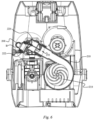
FIG. 9 is a schematic sectional view of a control box in a filtering mode according to another example embodiment; -
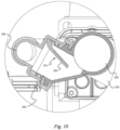
FIG. 10 is a partial enlarged view of part C ofFIG. 9 ; -
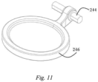
FIG. 11 is a partial schematic structural diagram of a first swing check one-way valve ofFIG. 9 ; -
FIG. 12 is a schematic sectional view of the control box ofFIG. 9 in a massage mode; and -
FIG. 13 is a partial enlarged view of part D ofFIG. 12 . - Reference will now be made in detail to example embodiments which are illustrated in the accompanying drawings, wherein like reference numerals refer to like elements throughout. In this regard, the example embodiments may have different forms and may not be construed as being limited to the descriptions set forth herein.
- It will be understood that the terms "include," "including", "comprise, and/or "comprising," when used in this specification, specify the presence of stated features, integers, steps, operations, elements, and/or components, but do not preclude the presence or addition of one or more other features, integers, steps, operations, elements, components, and/or groups thereof.
- It will be further understood that, although the terms "first," "second," "third," etc., may be used herein to describe various elements, components, regions, layers and/or sections, these elements, components, regions, layers and/or sections may not be limited by these terms. These terms are only used to distinguish one element, component, region, layer or section from another element, component, region, layer or section.
- As used herein, the term "and/or" includes any and all combinations of one or more of the associated listed items. Expressions such as "at least one of," when preceding a list of elements, modify the entire list of elements and do not modify the individual elements of the list. In addition, the terms such as "unit," "-er (-or)," and "module" described in the specification refer to an element for performing at least one function or operation, and may be implemented in hardware, software, or the combination of hardware and software.
- Various terms are used to refer to particular system components. Different companies may refer to a component by different names - this document does not intend to distinguish between components that differ in name but not function.
- Matters of these example embodiments that are obvious to those of ordinary skill in the technical field to which these example embodiments pertain may not be described here in detail.
-
FIG. 1 illustrates a schematic diagram of amassage pool 100 and acontrol box 200 according to an example embodiment. Thecontrol box 200 is connected to themassage pool 100. One ormore massage nozzles 102 are provided on an inner wall of themassage pool 100. - As discussed herein, an inlet flow direction and an outlet flow direction of water represented by "inlet" in "a filtering water inlet pipe" and "a massage water inlet pipe" and "outlet" in "a water outlet pipe" are described with respect to the control box. That is, a flow direction from the
massage pool 100 to the control box is described as an "inlet" direction, and a flow direction from thecontrol box 200 to themassage pool 100 is described as an "outlet" direction. - With reference to
FIG. 2 , when thecontrol box 200 is set to a filtering mode, a filtering water pump unit in thecontrol box 200 operates, while a massage water pump unit in the control box does not operate. Water in themassage pool 100 flows from themassage pool 100 into a filteringwater pump body 204 through a filteringwater inlet pipe 206; is pumped by the filteringwater pump body 204 to afiltering output pipe 208; and then flows back to themassage pool 100 via awater outlet pipe 230. A first flow path is defined as starting at an end of the filtering output pipe close to the filtering water pump body and ending at a connection between a first branch pipe and a second branch pipe or a third branch pipe. - When the
control box 200 is set to a massage mode, the massage water pump unit in thecontrol box 200 operates, and the filtering water pump unit in the control box does not operate. Water in themassage pool 100 flows from themassage pool 100 into a massagewater pump body 214 through a massagewater inlet pipe 216; is pumped by the massagewater pump body 214 to amassage outlet pipe 218, then flows back to a water conduit provided in themassage pool 100 via thewater outlet pipe 230; and is ejected from themassage nozzle 102. A water conduit path is defined as starting at an end of the massage output pipe, close to the massage water pump body, and ending at a connection between the second branch pipe and the third branch pipe. - It should be noted that in the filtering mode and massage mode described above, water passes through a
third branch pipe 226 after being pumped from the filteringwater pump body 204 or the massagewater pump body 214, and then flows back to themassage pool 200 via thewater outlet pipe 230 connected to thethird branch pipe 226. In one or more example embodiments, because a water conduit in the filtering water pump unit is in communication with a water conduit in the massage water pump unit, to avoid an undesired flow splitting of water caused by water conduits in communication in various running modes, a valve may be provided inside thecontrol box 200. The valve may be used for guiding a flow direction of water. - With reference to
FIGs. 2 and3 , a partial schematic diagram of acontrol box 200 according to an example embodiment is shown.FIG. 2 shows a filtering water pump unit, a massage water pump unit, a three-way connecting pipe fitting 220, awater outlet pipe 230, anair pump body 264, a positive temperature coefficient (PTC)heater 270, and other elements described below. InFIG. 2 , the filtering water pump unit comprises: a filteringwater inlet pipe 206, a filteringwater pump body 204 connected to the filteringwater inlet pipe 206, and afiltering output pipe 208 connected to the filteringwater pump body 204. The filteringwater inlet pipe 206 extends in a horizontal direction outside a housing of the control box. The massage water pump unit comprises: a massagewater inlet pipe 216, a massagewater pump body 214 connected to the massagewater inlet pipe 216, and amassage output pipe 218 connected to the massagewater pump body 214. The massagewater inlet pipe 216 extends in the horizontal direction outside the housing of the control box. The three-way connecting pipe fitting 220 comprises: afirst branch pipe 222 connected to thefiltering output pipe 208; asecond branch pipe 224 connected to themassage output pipe 218; and athird branch pipe 226 connected to thewater outlet pipe 230. Thus, thefirst branch pipe 222 has a distal end connected to thefiltering output pipe 208, and a proximal end connected to a juncture of thesecond branch pipe 224, where thethird branch pipe 226 is connected to thesecond branch pipe 224. Thesecond branch pipe 224 has a distal end connected to themassage output pipe 218, and a juncture at a proximal end, where thethird branch pipe 226 and thefirst branch pipe 222 are connected to thesecond branch pipe 224. Thethird branch pipe 226 has a distal end connected to the water outlet pipe and a proximal end connected to the juncture in thesecond branch pipe 224. In the example embodiment shown inFIG. 2 , thefirst branch pipe 222 is staggered downward from thesecond branch pipe 224, and thethird branch pipe 226 is connected to thesecond branch pipe 224. This enables thewater outlet pipe 230 to be disposed above thefiltering output pipe 208 and themassage output pipe 218. Thewater outlet pipe 230 is used for connecting to a water inlet conduit of the massage pool. One end of thewater outlet pipe 230 is joined to thethird branch pipe 226, and the other end extends in the horizontal direction outside the housing of the control box. The air pump unit comprises an airpump output pipe 268, extending in the horizontal direction, and anair pump body 264. ThePTC heater 270 is disposed in a substantially horizontal position and is connected to thefiltering output pipe 208. - As discussed above, the
first branch pipe 222 of the three-way connecting pipe fitting 220 inFIG. 2 is staggered downward from thesecond branch pipe 224. This enables thethird branch pipe 226, connected to thesecond branch pipe 224 at the juncture in thesecond branch pipe 224, to be disposed at a height greater than or equal to heights at which thefirst branch pipe 222 and thesecond branch pipe 224 are disposed. It is further arranged that thewater outlet pipe 230 is disposed at a height that is greater than or equal to heights at which thefiltering output pipe 208, themassage output pipe 218, and the three-way connecting pipe fitting 220 are disposed. That is, none of the heights at which other water conduits in the control box are disposed is greater than the height at which thewater outlet pipe 230 is disposed. This example arrangement enables the control box to have a compact structure and an appropriate layout, and may aid in preventing air from remaining in a water conduit of thecontrol box 200 due to low density. In addition, air may further be prevented from remaining at the PTC heater to cause the PTC heater to fail to detect water temperature as expected. - In one or more example embodiments, the foregoing air pump unit may be omitted from the control box.
- In one or more example embodiments, the foregoing PTC heater may be omitted from the control box. In this case, the
filtering output pipe 208 may be directly connected to thefirst branch pipe 222 of the three-way connecting pipe fitting 220 and the filteringwater pump body 204. - With reference to
FIG. 3 to FIG. 7 ,FIG. 3 andFIG. 4 show acontrol box 200 in a filtering mode according to an example embodiment. With reference toFIG. 3 andFIG. 4 , thefiltering output pipe 208 and themassage output pipe 218 are respectively connected to thefirst branch pipe 222 and thesecond branch pipe 224 of the three-way connecting pipe fitting 220 by detachable threaded connectingmembers 228. Alift valve 252 is provided at the juncture of thesecond branch pipe 224, where thethird branch pipe 226 is connected to thesecond branch pipe 224. Thelift valve 252 is configured to alternately allow water flow from thefirst branch pipe 222 into the juncture of thesecond branch pipe 222 and into thethird branch pipe 224, or to allow water flow from themassage output pipe 218 into the distal end of the second branch pipe into the juncture of thesecond branch pipe 222 and into thethird branch pipe 224. Thelift valve 252 comprises: avalve stem 254, asecond valve clack 256 capable of reciprocating along thevalve stem 254, and asecond valve seat 258 for fixing thevalve stem 254. In the filtering mode, the filtering water pump unit is in operation, and water from themassage pool 100 is pumped by the filteringwater pump body 204, sequentially flows through thefiltering output pipe 208 and thefirst branch pipe 222, and applies a force to afirst surface 257 of thesecond valve clack 256. This force enables thesecond valve clack 256 to fall along thevalve stem 254 to thesecond valve seat 258, to open a first flow path and at the same time to close a second flow path. Water from thefirst branch pipe 222 flows to the juncture in thesecond branch pipe 224, sequentially flows through thethird branch pipe 226 and thewater outlet pipe 230, and finally flows back into themassage pool 100. - As shown in
FIG. 5 , in an example embodiment, thesecond valve clack 256 has an arcshaped surface enabling thefirst surface 257 to form a concave surface toward thesecond valve seat 258. Thesecond valve seat 258 has a hollow cylindrical structure with three uniformly distributedspokes 261. End surfaces 262 of the threespokes 261 of thesecond valve seat 258 are inwardly concave. That is, thesecond valve seat 258 has a concave surface. The concave surface can adapt to thesecond valve clack 256. -
FIG. 6 andFIG. 7 show a control box in a massage mode according to an example embodiment. In the massage mode, the massage water pump unit is in operation, and water from themassage pool 100 is pumped by the massagewater pump body 214 into themassage output pipe 218, and applies a force to asecond surface 259 of thesecond valve clack 256. This force enables thesecond valve clack 256 to rise along thevalve stem 254 to a joint between thefirst branch pipe 222 and thesecond branch pipe 224, to open the second flow path, and at the same time, close the first flow path. Water from themassage output pipe 218 flows into the juncture in thesecond branch pipe 224, sequentially flows through thethird branch pipe 226 and thewater outlet pipe 230, then flows to a water conduit provided in themassage pool 100, and is finally ejected from themassage nozzle 102. - With the foregoing arrangement, the
lift valve 252 alternatively opens the first flow path for the filtered water or the second flow path for the massage water. -
FIG. 8 shows a partial schematic diagram of a control box according to another example embodiment. Elements which are the same as those discussed with reference toFIG. 2 are not repeatedly discussed here. InFIG. 8 , thefirst branch pipe 222 of the three-way connecting pipe fitting 222 is staggered down from thethird branch pipe 226, to enable a height at which thethird branch pipe 226, connected to the juncture of thesecond branch pipe 224, is disposed to be greater than or equal to heights at which thefirst branch pipe 222 and thesecond branch pipe 224 are disposed. A height at which thewater outlet pipe 230 is disposed is greater than or equal to heights at which thefiltering output pipe 208, themassage output pipe 218, and the three-way connecting pipe fitting 220 are disposed. That is, none of the heights at which other water conduits in the control box are disposed are greater than the height at which thewater outlet pipe 230 is disposed. Thefiltering output pipe 208 and themassage output pipe 218 are respectively connected to thefirst branch pipe 222 and thesecond branch pipe 224 by the detachable threaded connectingmembers 228. - With reference to
FIG. 9 to FIG. 13 ,FIG. 9 andFIG. 10 show a control box in a filtering mode according to another example embodiment. With reference toFIG. 9 andFIG. 10 , thefiltering output pipe 208 is connected to thefirst branch pipe 222 in a pluggable manner. Themassage output pipe 218 is connected to thesecond branch pipe 224 by the detachable threaded connectingmember 228. A first swing check one-way valve 242 is provided at the distal end of thefirst branch pipe 222, at the connection between thefirst branch pipe 222 and thefiltering output pipe 208. As illustrated, the first swing check one-way valve 242 is arranged at thefiltering output pipe 208. With reference toFIG. 10 andFIG. 11 , the first swing check one-way valve 242 comprises: afirst pivot shaft 244, afirst valve clack 246 pivotable around thefirst pivot shaft 244, and a first valve seat. Thefirst valve clack 246 is adapted to thefiltering output pipe 208, and is pivotably connected to thefirst pivot shaft 244. Thefirst pivot shaft 244 is pivotably or fixedly connected to thefiltering output pipe 208 by the first valve seat (not shown). In the filtering mode, the filtering water pump unit is in operation, and water from themassage pool 100 is pumped by the filteringwater pump body 204 to thefiltering output pipe 208, and applies a force to athird surface 249 of thefirst valve clack 246. This force enables thefirst valve clack 246 to pivot around thefirst pivot shaft 244 and to be open, to open the first flow path. Water from thefiltering output pipe 208 sequentially flows into thefirst branch pipe 222, thethird branch pipe 226, and thewater outlet pipe 230, and finally flows back to themassage pool 100. It should also be noted that some water is diverted by thethird branch pipe 226 to flow into thesecond branch pipe 224, and continues to flow to themassage output pipe 218. That is, some of the water is diverted onto the second flow path to flow to themassage output pipe 218. -
FIG. 12 andFIG. 13 are schematic sectional views of the control box inFIG. 9 in a massage mode. In the massage mode, the massage water pump unit is in operation, and water from themassage pool 100 is pumped by the massagewater pump body 214 to themassage output pipe 218, sequentially flows through thesecond branch pipe 224, thethird branch pipe 226, and thewater outlet pipe 230, flows to a water conduit provided in themassage pool 100, and is finally ejected from themassage nozzle 102. Some of the water flowing to thesecond branch pipe 224 is diverted to flow to thefirst branch pipe 222, and applies a force to afourth surface 248 of thefirst valve clack 246 at a connection between thefirst branch pipe 222 and thefiltering output pipe 208. This force enables thefirst valve clack 246 to pivot in an opposite direction around thefirst pivot shaft 244 to be closed, and to close the first flow path. - With the foregoing arrangement, the first swing check one-
way valve 242 may open or close the first flow path. - According to one or more example embodiments, the first swing check one-way valve may be disposed at the connection between the first branch pipe and the filtering output pipe and may be arranged at the first branch pipe. According to one or more other example embodiments, the first swing check one-way valve may be disposed at the filtering output pipe along the first flow path.
- According to one or more example embodiments, the first swing check one-way valve may be disposed as an auto-reset swing check one-way valve. In other words, when no water applies a force to the first swing check one-way valve, the first swing check one-way valve may automatically close to close the first flow path.
- According to one or more example embodiments, to avoid unnecessary flow diversion of water in the filtering mode into the
massage output pipe 218, while the first swing check one-way valve 242 is provided at a connection between thefirst branch pipe 222 and thefiltering output pipe 208, a second swing check one-way valve may be further provided at the massage output pipe. Similar to the structure of the first swing check one-way valve 242, the second swing check one-way valve may include a second pivot shaft, a third valve clack pivotable around the second pivot shaft, and a third valve seat. The third valve clack may be adapted to themassage output pipe 218, and be pivotably connected to the second pivot shaft. The second pivot shaft may be pivotably or fixedly connected to the massage output pipe by the third valve seat. - According to one or more example embodiments, the filtering water pump unit is in operation in the filtering mode, and water from the
massage pool 100 is pumped by the filteringwater pump body 204 to thefiltering output pipe 208, and the water applies a force to thethird surface 249 of thefirst valve clack 246. This force enables thefirst valve clack 246 to pivot around thefirst pivot shaft 244 to be open, to open the first flow path. Water from thefiltering output pipe 208 sequentially flows through thefirst branch pipe 222, thethird branch pipe 226, and thewater outlet pipe 230, and finally flows back to themassage pool 100. It should also be noted that, meanwhile, some water may be undesirably diverted, via thethird branch pipe 226, along the second flow path to flow to themassage output pipe 218. In this case, water flows through the second swing check one-way valve, and applies a force to a sixth surface of the third valve clack of the second swing check one-way valve, to enable the third valve clack to pivot in an opposite direction around the second pivot shaft to be closed, to close the second flow path. In other words, in the filtering mode in this example embodiment, thefirst valve clack 246 is opened to open the first flow path, and at the same time the third valve clack is closed to close the second flow path. - Similarly, in the massage mode in one or more example embodiments, water flows through the second swing check one-way valve, and applies a force to a fifth surface of the third valve clack of the second swing check one-way valve, to enable the third valve clack to pivot around the second pivot shaft to be open, to open the second flow path. Water from the
massage output pipe 208 sequentially flows through the second branch pipe, the third branch pipe, and the water outlet pipe, then flows to the water conduit provided in themassage pool 100, and is finally ejected from themassage nozzle 102. It should also be noted that, meanwhile, some water is diverted, via the third branch pipe, along the first flow path to flow to the filtering output pipe. In this case, water flows through the first swing check one-way valve, and applies a force to a fourth surface of the first valve clack, to enable the first valve clack to pivot in an opposite direction around the first pivot shaft to be closed, to close the first flow path. In other words, in the massage mode in this example embodiment, the third valve clack is opened to open the second flow path, and at the same time the first valve clack is closed to close the first flow path. - With the foregoing example arrangement, the first swing check one-way valve and the second swing check one-way valve cooperate with each other to alternatively open the first flow path or the second flow path.
- According to one or more example embodiments, the first swing check one-way valve may be disposed along the first flow path. For example, the first swing check one-way valve may be disposed at the filtering output pipe. Similarly, the second swing check one-way valve may be disposed along the second flow path. For example, the second swing check one-way valve may be disposed at the second branch pipe.
- According to one or more example embodiments, the second swing check one-way valve may be disposed as an auto-reset swing check one-way valve. In other words, when no water applies a force to the second swing check one-way valve, the second swing check one-way valve is automatically closed to close the second flow path.
- It may be understood that the example embodiments described herein may be considered in a descriptive sense only and not for purposes of limitation. Descriptions of features or aspects within each example embodiment may be considered as available for other similar features or aspects in other example embodiments.
Claims (10)
- A control box of a massage pool, the control box comprising:a filtering pump unit comprising: a filtering pump body (204), a filtering water inlet pipe (206) connected between the massage pool and the filtering pump body, and a filtering output pipe;a massage pump unit, the massage pump unit comprising: a massage pump body (214), a massage inlet pipe (216) connected between the massage pool and the massage pump body, and a massage output pipe (218);a water outlet pipe (230) configured to output water to the massage pool;a three-way connecting pipe fitting (220) comprising: a first branch pipe (222) having a distal end connected to the filtering output pipe (208), a second branch pipe (224) having a distal end connected to the massage output pipe (218), and a third branch pipe (226) having a distal end connected to the water outlet pipe (230); andat least one valve configured to alternately open and close a first flow path from the filtering output pipe through the first branch pipe.
- The control box according to claim 1, wherein the at least one valve is a first swing check one-way valve (242) comprising: a first pivot shaft (244), a first valve clack (246) pivotable around the first pivot shaft (244), and a first valve seat.
- The control box according to claim 1, wherein:the at least one valve is disposed in at least one of the filtering output pipe (208), the massage output pipe (218), and the three-way connecting pipe fitting (220); andthe at least one valve is configured to alternately open the first flow path and open a second flow path from the massage output pipe through the second branch pipe.
- The control box according to claim 3, wherein the at least one valve comprises:a first swing check one-way valve (242) disposed at a connection between the filtering output pipe and the first branch pipe; anda second swing check one-way valve disposed at a connection between the massage output pipe and the second branch pipe.
- The control box according to claim 2, wherein the first swing check one-way valve (242) is disposed at a connection between the filtering output pipe (208) and the first branch pipe (222).
- The control box according to claim 3, wherein the at least one valve is a lift valve (252) comprising: a valve stem (254), a valve clack (256) capable of reciprocating along the valve stem (254), and a valve seat (258).
- The control box according to claim 1, wherein a height at which the water outlet pipe (230) is disposed is greater than or equal to heights at which the filtering output pipe (208), the massage output pipe (218), and the three-way connecting pipe fitting (220) are disposed.
- The control box according to claim 1, wherein the control box (200) further comprises an air pump unit comprising an air pump body (264) and an air pump output pipe (268), the air pump output pipe (268) configured to be connected to an air inlet conduit of the massage pool (100).
- The control box according to claim 1, further comprising a heater (270) connected to the filtering output pipe (208).
- A massage pool, comprising the control box according to one of claims 1 to 9.
Applications Claiming Priority (1)
| Application Number | Priority Date | Filing Date | Title |
|---|---|---|---|
| CN202120489220.0U CN215081861U (en) | 2021-03-08 | 2021-03-08 | Jacuzzi Control Box and Jacuzzi |
Publications (3)
| Publication Number | Publication Date |
|---|---|
| EP4238545A1 true EP4238545A1 (en) | 2023-09-06 |
| EP4238545B1 EP4238545B1 (en) | 2026-01-28 |
| EP4238545B8 EP4238545B8 (en) | 2026-03-11 |
Family
ID=79340588
Family Applications (1)
| Application Number | Title | Priority Date | Filing Date |
|---|---|---|---|
| EP22159895.6A Active EP4238545B8 (en) | 2021-03-08 | 2022-03-03 | Control box of massage pool and massage pool |
Country Status (3)
| Country | Link |
|---|---|
| US (1) | US12433822B2 (en) |
| EP (1) | EP4238545B8 (en) |
| CN (1) | CN215081861U (en) |
Cited By (1)
| Publication number | Priority date | Publication date | Assignee | Title |
|---|---|---|---|---|
| US20240261183A1 (en) * | 2021-07-15 | 2024-08-08 | Intex Marketing Ltd. | An airway system of a massage pool, comprises an air pump and an airway unit |
Families Citing this family (1)
| Publication number | Priority date | Publication date | Assignee | Title |
|---|---|---|---|---|
| USD1041029S1 (en) * | 2022-03-03 | 2024-09-03 | Boomer Shroomer Llc | Inflatable monotub |
Citations (5)
| Publication number | Priority date | Publication date | Assignee | Title |
|---|---|---|---|---|
| US5899231A (en) * | 1996-12-30 | 1999-05-04 | Drori; Mordecki | Automatic three-way valve |
| US20040045613A1 (en) * | 2002-09-06 | 2004-03-11 | Waterway Plastics, Inc. | Diverter valve |
| US20110114341A1 (en) * | 2009-11-18 | 2011-05-19 | Claffey Paul J | Integrated fire fighting valve and system |
| US20140277777A1 (en) * | 2013-03-13 | 2014-09-18 | Hayward Industries, Inc. | Local Feature Controller For Pool and Spa Equipment |
| US9856667B2 (en) * | 2011-05-27 | 2018-01-02 | Wesley O. Cox | Low gravity fed water system without submersed drains within the bathing chamber for pools and spas |
Family Cites Families (39)
| Publication number | Priority date | Publication date | Assignee | Title |
|---|---|---|---|---|
| US1687860A (en) * | 1927-06-01 | 1928-10-16 | George S Fosnaugh | Slush-pump valve |
| US2223699A (en) * | 1938-05-21 | 1940-12-03 | Carl A Norgren | Check valve |
| US2488086A (en) * | 1945-08-27 | 1949-11-15 | Nordberg Manufacturing Co | Fluid pressure system |
| US2810397A (en) * | 1955-11-17 | 1957-10-22 | Line Scale Company Inc | Nylon pump valve with spring retainer |
| US3441051A (en) * | 1965-06-03 | 1969-04-29 | Sinclair Research Inc | Check valve |
| US3965926A (en) * | 1975-08-25 | 1976-06-29 | Trw Inc. | Flapper valve with independent plate suspension |
| US4043358A (en) * | 1976-02-02 | 1977-08-23 | Victaulic Company Of America | Flapper check valve |
| US4535808A (en) * | 1983-07-08 | 1985-08-20 | Dicken Manufacturing Company | Check valve |
| US4546505A (en) * | 1984-04-16 | 1985-10-15 | Wakenshaw John A | Portable spa |
| US4761838A (en) * | 1987-05-04 | 1988-08-09 | Nancy A. Brown | Contrast-healing water spa system |
| US4893362A (en) * | 1988-04-01 | 1990-01-16 | Murphy Pierce M | Portable spa |
| US4859345A (en) * | 1988-08-26 | 1989-08-22 | Jitsuo Inagaki | Bath water heater and circulator-purifier apparatus |
| US5031255A (en) * | 1990-01-10 | 1991-07-16 | Associated Mills, Inc. | Whirlpool |
| US5135361A (en) * | 1991-03-06 | 1992-08-04 | William W. Gotherman | Pumping station in a water flow system |
| US5287567A (en) * | 1993-03-12 | 1994-02-22 | Horner Equipment Of Florida, Inc. | Hydraulic isolation manifold |
| US5546981A (en) * | 1995-01-12 | 1996-08-20 | Gilbarco, Inc. | Check valve |
| US5526538A (en) * | 1995-05-04 | 1996-06-18 | Hurrican Products Incorporated | Water circulation and heating system for spas |
| US7060180B1 (en) * | 1999-10-15 | 2006-06-13 | Barnes Ronald L | Ozone generator retrofit apparatus for jetted tubs and spas |
| US6003166A (en) * | 1997-12-23 | 1999-12-21 | Icon Health And Fitness, Inc. | Portable spa |
| US6357059B1 (en) * | 2000-03-28 | 2002-03-19 | Pleasure Time Products (Hk) Limited | Portable spa |
| US6279177B1 (en) * | 2000-04-06 | 2001-08-28 | Cary Gloodt | Method and apparatus for purging water from a whirlpool system |
| US6470508B2 (en) * | 2000-11-08 | 2002-10-29 | Watkins Manufacturing Corporation | Air check valve system for a spa |
| US20050005349A1 (en) * | 2003-07-07 | 2005-01-13 | Saratoga Spa & Bath Co., Inc. | Systems, methods, and valves for providing pressurized water to a plurality of water jets in a bathing enclosure |
| US7784489B2 (en) * | 2005-08-11 | 2010-08-31 | Envirotech Pumpsystems, Inc. | Check valve for a self-priming pump |
| CA2517785C (en) * | 2005-09-01 | 2009-06-02 | Masco Canada Limited | Check valve |
| US20070094784A1 (en) * | 2005-09-07 | 2007-05-03 | Trong Tran | Spa air system |
| US7695250B2 (en) * | 2005-11-02 | 2010-04-13 | Gm Global Technology Operations, Inc. | Dual pump assembly |
| DE102008040665A1 (en) * | 2008-07-24 | 2010-06-17 | Zf Friedrichshafen Ag | Method for controlling the oil supply device of a planetary automatic transmission |
| US8453275B2 (en) * | 2009-03-05 | 2013-06-04 | May Manufacturing LLC | Combination bathtub and spa |
| AU2010291869A1 (en) * | 2009-09-02 | 2012-04-19 | Evolve Supply Chain Pty Ltd | A filtration unit system |
| US20130092261A1 (en) * | 2011-10-13 | 2013-04-18 | Flomatic Corporation | Check valve |
| US9885360B2 (en) * | 2012-10-25 | 2018-02-06 | Pentair Flow Technologies, Llc | Battery backup sump pump systems and methods |
| US9611947B2 (en) * | 2015-06-09 | 2017-04-04 | Ge Aviation Systems Llc | Valve assembly and method of controlling flow of fluid |
| US9573038B1 (en) * | 2015-10-08 | 2017-02-21 | Waterway Plastics | Variable speed swim spa system |
| CN108685496A (en) * | 2017-03-31 | 2018-10-23 | 太琦科技股份有限公司 | Automatic pipeline cleaning system of massage bath equipment |
| EP3418611B1 (en) * | 2017-06-21 | 2020-04-22 | Hamilton Sundstrand Corporation | Check valves |
| CN207332380U (en) * | 2017-07-28 | 2018-05-08 | 上海荣威塑胶工业有限公司 | The massage pipe-line system of Inflation water pond |
| US10918569B2 (en) * | 2019-07-15 | 2021-02-16 | Wexco Incorporated | Integrated manifold and valve assembly |
| CN112443181B (en) * | 2019-09-03 | 2024-12-24 | 东辉休闲运动用品(上海)有限公司 | Water circulation pipeline, control box and massage pool |
-
2021
- 2021-03-08 CN CN202120489220.0U patent/CN215081861U/en active Active
-
2022
- 2022-03-03 EP EP22159895.6A patent/EP4238545B8/en active Active
- 2022-03-07 US US17/688,018 patent/US12433822B2/en active Active
Patent Citations (5)
| Publication number | Priority date | Publication date | Assignee | Title |
|---|---|---|---|---|
| US5899231A (en) * | 1996-12-30 | 1999-05-04 | Drori; Mordecki | Automatic three-way valve |
| US20040045613A1 (en) * | 2002-09-06 | 2004-03-11 | Waterway Plastics, Inc. | Diverter valve |
| US20110114341A1 (en) * | 2009-11-18 | 2011-05-19 | Claffey Paul J | Integrated fire fighting valve and system |
| US9856667B2 (en) * | 2011-05-27 | 2018-01-02 | Wesley O. Cox | Low gravity fed water system without submersed drains within the bathing chamber for pools and spas |
| US20140277777A1 (en) * | 2013-03-13 | 2014-09-18 | Hayward Industries, Inc. | Local Feature Controller For Pool and Spa Equipment |
Cited By (2)
| Publication number | Priority date | Publication date | Assignee | Title |
|---|---|---|---|---|
| US20240261183A1 (en) * | 2021-07-15 | 2024-08-08 | Intex Marketing Ltd. | An airway system of a massage pool, comprises an air pump and an airway unit |
| US12128000B2 (en) * | 2021-07-15 | 2024-10-29 | Intex Marketing Ltd. | Airway system of a massage pool, comprises an air pump and an airway unit |
Also Published As
| Publication number | Publication date |
|---|---|
| US20220280382A1 (en) | 2022-09-08 |
| US12433822B2 (en) | 2025-10-07 |
| CN215081861U (en) | 2021-12-10 |
| EP4238545B8 (en) | 2026-03-11 |
| EP4238545B1 (en) | 2026-01-28 |
Similar Documents
| Publication | Publication Date | Title |
|---|---|---|
| US12433822B2 (en) | Control box of massage pool and massage pool | |
| US7721761B2 (en) | Diverter integrated into a side sprayer | |
| US8388566B2 (en) | Oxygenator with integrated arterial filter including filter frame | |
| EP3135841B1 (en) | Water spraying device for inflatable pool | |
| JPH0751515A (en) | Full flow-bypass combined filter | |
| JP6311537B2 (en) | Fuel supply device | |
| CN108361438A (en) | Bypass check valve and Venturi with the bypass check valve | |
| JP6358591B2 (en) | Emulsion engine system | |
| CN105396242A (en) | A fire truck piping system | |
| EP2465554B1 (en) | Oxygenator with integrated arterial filter including filter frame | |
| JP2007519854A (en) | Connecting valve structure for fuel supply module | |
| US11772024B2 (en) | Filter assembly with a diffuser | |
| GB2495852A (en) | A turbomachine blade incidence control system | |
| US20030226591A1 (en) | Lavatory flush tank silent-operating fill device | |
| KR102216548B1 (en) | Check valve | |
| CN111868372B (en) | Fuel pump assembly with split flow | |
| CN120120147B (en) | Precooling System and Precooling Method for Multi-Aircraft Cryogenic Liquid Launch Vehicle | |
| EP4570063A1 (en) | A damper arrangement for a homogenizer | |
| KR101930037B1 (en) | Exhaust gas handling system for small sized ship comprising assembled mixing chamber | |
| WO2015146713A1 (en) | Emulsion engine system and emulsion fuel feeder | |
| JP3357889B2 (en) | Sake server | |
| JP7444617B2 (en) | Drain bolt and fuel filter | |
| EP1918532B1 (en) | Desuperheater apparatus for steam lines | |
| KR20200046304A (en) | Housing device for booster pump | |
| IT201600104206A1 (en) | ASSEMBLY ASSEMBLY FOR A WATER PUMP UNIT FOR A VEHICLE COOLING SYSTEM |
Legal Events
| Date | Code | Title | Description |
|---|---|---|---|
| PUAI | Public reference made under article 153(3) epc to a published international application that has entered the european phase |
Free format text: ORIGINAL CODE: 0009012 |
|
| STAA | Information on the status of an ep patent application or granted ep patent |
Free format text: STATUS: THE APPLICATION HAS BEEN PUBLISHED |
|
| AK | Designated contracting states |
Kind code of ref document: A1 Designated state(s): AL AT BE BG CH CY CZ DE DK EE ES FI FR GB GR HR HU IE IS IT LI LT LU LV MC MK MT NL NO PL PT RO RS SE SI SK SM TR |
|
| STAA | Information on the status of an ep patent application or granted ep patent |
Free format text: STATUS: REQUEST FOR EXAMINATION WAS MADE |
|
| 17P | Request for examination filed |
Effective date: 20240304 |
|
| RBV | Designated contracting states (corrected) |
Designated state(s): AL AT BE BG CH CY CZ DE DK EE ES FI FR GB GR HR HU IE IS IT LI LT LU LV MC MK MT NL NO PL PT RO RS SE SI SK SM TR |
|
| STAA | Information on the status of an ep patent application or granted ep patent |
Free format text: STATUS: EXAMINATION IS IN PROGRESS |
|
| 17Q | First examination report despatched |
Effective date: 20241129 |
|
| GRAP | Despatch of communication of intention to grant a patent |
Free format text: ORIGINAL CODE: EPIDOSNIGR1 |
|
| STAA | Information on the status of an ep patent application or granted ep patent |
Free format text: STATUS: GRANT OF PATENT IS INTENDED |
|
| INTG | Intention to grant announced |
Effective date: 20250820 |
|
| GRAS | Grant fee paid |
Free format text: ORIGINAL CODE: EPIDOSNIGR3 |
|
| GRAA | (expected) grant |
Free format text: ORIGINAL CODE: 0009210 |
|
| STAA | Information on the status of an ep patent application or granted ep patent |
Free format text: STATUS: THE PATENT HAS BEEN GRANTED |
|
| AK | Designated contracting states |
Kind code of ref document: B1 Designated state(s): AL AT BE BG CH CY CZ DE DK EE ES FI FR GB GR HR HU IE IS IT LI LT LU LV MC MK MT NL NO PL PT RO RS SE SI SK SM TR |
|
| REG | Reference to a national code |
Ref country code: CH Ref legal event code: F10 Free format text: ST27 STATUS EVENT CODE: U-0-0-F10-F00 (AS PROVIDED BY THE NATIONAL OFFICE) Effective date: 20260128 Ref country code: GB Ref legal event code: FG4D Ref country code: CH Ref legal event code: Y10 Free format text: ST27 STATUS EVENT CODE: U-0-0-Y10-Y00 (AS PROVIDED BY THE NATIONAL OFFICE) Effective date: 20260128 |
|
| REG | Reference to a national code |
Ref country code: CH Ref legal event code: Q17 Free format text: ST27 STATUS EVENT CODE: U-0-0-Q10-Q17 (AS PROVIDED BY THE NATIONAL OFFICE) Effective date: 20260211 |
|
| REG | Reference to a national code |
Ref country code: DE Ref legal event code: R096 Ref document number: 602022029046 Country of ref document: DE |
|
| REG | Reference to a national code |
Ref country code: IE Ref legal event code: FG4D |
|
| PGFP | Annual fee paid to national office [announced via postgrant information from national office to epo] |
Ref country code: GB Payment date: 20260323 Year of fee payment: 5 |
|
| PGFP | Annual fee paid to national office [announced via postgrant information from national office to epo] |
Ref country code: DE Payment date: 20260313 Year of fee payment: 5 |
|
| PGFP | Annual fee paid to national office [announced via postgrant information from national office to epo] |
Ref country code: AT Payment date: 20260301 Year of fee payment: 5 |
|
| PGFP | Annual fee paid to national office [announced via postgrant information from national office to epo] |
Ref country code: FR Payment date: 20260330 Year of fee payment: 5 |