EP4238463B1 - Feed chute assembly for a food processor - Google Patents
Feed chute assembly for a food processor Download PDFInfo
- Publication number
- EP4238463B1 EP4238463B1 EP22188899.3A EP22188899A EP4238463B1 EP 4238463 B1 EP4238463 B1 EP 4238463B1 EP 22188899 A EP22188899 A EP 22188899A EP 4238463 B1 EP4238463 B1 EP 4238463B1
- Authority
- EP
- European Patent Office
- Prior art keywords
- feed chute
- pusher
- channel
- rib
- linkage
- Prior art date
- Legal status (The legal status is an assumption and is not a legal conclusion. Google has not performed a legal analysis and makes no representation as to the accuracy of the status listed.)
- Active
Links
Images




Classifications
-
- A—HUMAN NECESSITIES
- A47—FURNITURE; DOMESTIC ARTICLES OR APPLIANCES; COFFEE MILLS; SPICE MILLS; SUCTION CLEANERS IN GENERAL
- A47J—KITCHEN EQUIPMENT; COFFEE MILLS; SPICE MILLS; APPARATUS FOR MAKING BEVERAGES
- A47J43/00—Implements for preparing or holding food, not provided for in other groups of this subclass
- A47J43/04—Machines for domestic use not covered elsewhere, e.g. for grinding, mixing, stirring, kneading, emulsifying, whipping or beating foodstuffs, e.g. power-driven
- A47J43/07—Parts or details, e.g. mixing tools, whipping tools
-
- A—HUMAN NECESSITIES
- A47—FURNITURE; DOMESTIC ARTICLES OR APPLIANCES; COFFEE MILLS; SPICE MILLS; SUCTION CLEANERS IN GENERAL
- A47J—KITCHEN EQUIPMENT; COFFEE MILLS; SPICE MILLS; APPARATUS FOR MAKING BEVERAGES
- A47J43/00—Implements for preparing or holding food, not provided for in other groups of this subclass
- A47J43/04—Machines for domestic use not covered elsewhere, e.g. for grinding, mixing, stirring, kneading, emulsifying, whipping or beating foodstuffs, e.g. power-driven
- A47J43/07—Parts or details, e.g. mixing tools, whipping tools
- A47J43/075—Safety devices
- A47J43/0761—Safety devices for machines with tools driven from the lower side
- A47J43/0794—Safety devices for machines with tools driven from the lower side in which operation is not possible without the use of a food pusher
-
- A—HUMAN NECESSITIES
- A47—FURNITURE; DOMESTIC ARTICLES OR APPLIANCES; COFFEE MILLS; SPICE MILLS; SUCTION CLEANERS IN GENERAL
- A47J—KITCHEN EQUIPMENT; COFFEE MILLS; SPICE MILLS; APPARATUS FOR MAKING BEVERAGES
- A47J43/00—Implements for preparing or holding food, not provided for in other groups of this subclass
- A47J43/04—Machines for domestic use not covered elsewhere, e.g. for grinding, mixing, stirring, kneading, emulsifying, whipping or beating foodstuffs, e.g. power-driven
- A47J43/046—Machines for domestic use not covered elsewhere, e.g. for grinding, mixing, stirring, kneading, emulsifying, whipping or beating foodstuffs, e.g. power-driven with tools driven from the bottom side
-
- A—HUMAN NECESSITIES
- A47—FURNITURE; DOMESTIC ARTICLES OR APPLIANCES; COFFEE MILLS; SPICE MILLS; SUCTION CLEANERS IN GENERAL
- A47J—KITCHEN EQUIPMENT; COFFEE MILLS; SPICE MILLS; APPARATUS FOR MAKING BEVERAGES
- A47J43/00—Implements for preparing or holding food, not provided for in other groups of this subclass
- A47J43/04—Machines for domestic use not covered elsewhere, e.g. for grinding, mixing, stirring, kneading, emulsifying, whipping or beating foodstuffs, e.g. power-driven
- A47J43/07—Parts or details, e.g. mixing tools, whipping tools
- A47J43/0716—Parts or details, e.g. mixing tools, whipping tools for machines with tools driven from the lower side
-
- A—HUMAN NECESSITIES
- A47—FURNITURE; DOMESTIC ARTICLES OR APPLIANCES; COFFEE MILLS; SPICE MILLS; SUCTION CLEANERS IN GENERAL
- A47J—KITCHEN EQUIPMENT; COFFEE MILLS; SPICE MILLS; APPARATUS FOR MAKING BEVERAGES
- A47J43/00—Implements for preparing or holding food, not provided for in other groups of this subclass
- A47J43/04—Machines for domestic use not covered elsewhere, e.g. for grinding, mixing, stirring, kneading, emulsifying, whipping or beating foodstuffs, e.g. power-driven
- A47J43/07—Parts or details, e.g. mixing tools, whipping tools
- A47J43/075—Safety devices
-
- A—HUMAN NECESSITIES
- A47—FURNITURE; DOMESTIC ARTICLES OR APPLIANCES; COFFEE MILLS; SPICE MILLS; SUCTION CLEANERS IN GENERAL
- A47J—KITCHEN EQUIPMENT; COFFEE MILLS; SPICE MILLS; APPARATUS FOR MAKING BEVERAGES
- A47J43/00—Implements for preparing or holding food, not provided for in other groups of this subclass
- A47J43/04—Machines for domestic use not covered elsewhere, e.g. for grinding, mixing, stirring, kneading, emulsifying, whipping or beating foodstuffs, e.g. power-driven
- A47J43/07—Parts or details, e.g. mixing tools, whipping tools
- A47J43/075—Safety devices
- A47J43/0761—Safety devices for machines with tools driven from the lower side
- A47J43/0772—Safety devices for machines with tools driven from the lower side activated by the proper positioning of the cover
-
- B—PERFORMING OPERATIONS; TRANSPORTING
- B26—HAND CUTTING TOOLS; CUTTING; SEVERING
- B26D—CUTTING; DETAILS COMMON TO MACHINES FOR PERFORATING, PUNCHING, CUTTING-OUT, STAMPING-OUT OR SEVERING
- B26D7/00—Details of apparatus for cutting, cutting-out, stamping-out, punching, perforating, or severing by means other than cutting
- B26D7/06—Arrangements for feeding or delivering work of other than sheet, web, or filamentary form
- B26D7/0641—Arrangements for feeding or delivering work of other than sheet, web, or filamentary form using chutes, hoppers, magazines
-
- B—PERFORMING OPERATIONS; TRANSPORTING
- B26—HAND CUTTING TOOLS; CUTTING; SEVERING
- B26D—CUTTING; DETAILS COMMON TO MACHINES FOR PERFORATING, PUNCHING, CUTTING-OUT, STAMPING-OUT OR SEVERING
- B26D2210/00—Machines or methods used for cutting special materials
- B26D2210/02—Machines or methods used for cutting special materials for cutting food products, e.g. food slicers
Definitions
- This disclosure relates generally to motorized food processors and, more particularly, to a feed chute assembly for use with food processors.
- Food processors offer a convenient alternative to chopping or dicing by hand, and often come with a range of operational settings and modes adapted to provide specific types or amounts of food processing catered to particular food products.
- Current food processors often include a feed chute for introducing food into the food processor for cutting by the internal blades. Many consumers prefer a wider feed chute for introducing more and larger ingredients, thereby shortening food preparation time and adding convenience.
- food processors with sufficiently large feed chutes usually require safety mechanisms that prevent or at least minimize injury to the consumers' hands as a result of introducing the food into the chute. Such mechanisms can make it more difficult for the user to clean the feed chute after use.
- US2014/021278A1 describes a food processor that is provided with a wide feed tube.
- the food processor has a pusher that cooperates with a safety mechanism.
- the safety mechanism comprises a linkage assembly that prevents the food processor's motor from operating unless the pusher is inserted into the feed tube.
- US2003/205635A1 discloses a safety device for a food processor, where the switching-on of the motor depends on the presence of a pusher in the chute through which the products are introduced.
- the pusher has a rib with a lower end that bears against the upper end of a lid rod which bears against a bowl rod with a lower end that can bear against a switch.
- EP2832274A1 describes a juicer that includes a linkage assembly operated with a pusher and a trigger assembly for allowing power to be supplied to motor.
- the linkage assembly includes a pressure component set in the end of the opening of a feed tube.
- the pressure component is connected with a follower lever, the follower lever installed in the inside of the feed tube can be moved up and down.
- the trigger assembly includes some signal generators installed in the bottom of the follower lever and some inductors installed in juicer base correspond to the signal generators.
- the inductors are connected electrically with motor's control circuit.
- the feed chute assembly has a safety mechanism that helps prevent injury to the consumer while also providing an easy to clean surface.
- the feed chute assembly includes a lid coupleable to a container of the food processing system.
- the lid has a feed chute for introducing food towards rotating blades at the top of the container.
- a linkage cover housing a linkage component for activating the motor couples to the feed chute.
- the linkage cover defines a channel within an inside perimeter of the feed chute.
- a user inserts a pusher into the feed chute such that a rib on the pusher extends into the channel, operatively engaging the linkage component to activate the motor.
- the motor stops the spinning blades.
- the configuration of the channel of this disclosure makes it easier for the user to clean the feed chute assembly after use.
- the feed chute assembly of this invention comprises the features of claim 1.
- a method of operating a feed chute assembly comprises the features of claim 13.
- Preferred embodiments are the subject of the dependent claims.
- a feed chute assembly of a food processing system of this invention includes a lid coupleable to a first end of a container.
- the lid has a feed chute for introducing food into the container.
- a sidewall of the feed chute defines an inner and outer surface.
- a linkage cover couples to the feed chute.
- the linkage cover houses a linkage component and defines a channel within an inside perimeter of the feed chute. The channel at least partially communicates with a portion of the linkage component through an opening in the sidewall of the feed chute.
- a pusher is insertable into the feed chute.
- a portion of an outer surface of the pusher defines a recess with respect to a remainder of the outer surface of the pusher.
- a rib is disposed within the recess. The rib is configured for insertion into the channel of the linkage cover such that, when the rib is at least partially inserted into the channel, the rib operatively engages the portion of the linkage component.
- the linkage cover includes a first portion contacting the outer surface of the feed chute.
- the first portion houses the linkage component.
- a second portion contacts the inner surface of the feed chute.
- the second portion defines the channel extending vertically along the inner surface of the feed chute.
- the second portion includes a guide housing extending from the inner surface of the sidewall within the inside perimeter. The guide housing extends into the recess when the pusher is inserted into the feed chute.
- a shape of the rib corresponds to a shape of the channel.
- a cross section of the rib has one of an L-shape, T-shape, I-shape, and a wineglass shape.
- a length of the channel is less than a height of the inner surface of the feed chute. In some implementations, a portion of the inner surface of the feed chute located below the channel provides an easy to clean surface.
- the food processing system further includes a base housing a motor and the container has a second end removeably coupleable to the base. In some implementations, the portion of the linkage component is a roller operatively connected to a linkage system for activating the motor. In some implementations, the motor can only operate when the rib is at least partially inserted into the channel. In some implementations, wherein the pusher includes an upper peripheral rim extending outward from the sidewall. When the pusher is fully inserted into the feed chute, the upper peripheral rim covers a pilot opening of the channel. In some implementations, the pusher is configured to accommodate a second and smaller pusher.
- a method of operating a feed chute assembly of a food processing system of this disclosure includes inserting a pusher into a feed chute of a lid coupled to a first end of a container.
- a sidewall of the feed chute defines an inner and outer surface.
- a linkage cover couples to the feed chute.
- the linkage cover houses a linkage component and defines a channel within an inside perimeter of the feed chute. The channel at least partially communicates with a portion of the linkage component through an opening in the sidewall of the feed chute.
- a portion of an outer surface of the pusher defines a recess with respect to a remainder of the outer surface of the pusher.
- a rib is disposed within the recess. In response to the inserting of the pusher, the rib at least partially inserts into the channel of the linkage cover such that the rib engages the portion of the linkage component.
- the linkage cover includes a first portion contacting the outer surface of the feed chute.
- the first portion houses the linkage component.
- a second portion contacts the inner surface of the feed chute.
- the second portion defines the channel extending vertically along the inner surface of the feed chute.
- the second portion includes a guide housing extending from the inner surface of the sidewall within the inside perimeter. The guide housing extends into the recess when the pusher is inserted into the feed chute.
- a shape of the rib corresponds to a shape of the channel.
- a length of the channel is less than a height of the inner surface of the feed chute.
- engaging the rib with the portion of the linkage component includes engaging the rib with a roller operatively connected to a linkage system for activating a motor.
- the motor can only operate when the rib is at least partially inserted into the channel.
- the pusher includes an upper peripheral rim extending outward from the sidewall, and the method further includes covering a pilot opening of the channel with the upper peripheral rim when the pusher is fully inserted into the feed chute.
- the terms “about” and “substantially” represent the inherent degree of uncertainty attributed to any quantitative comparison, value, measurement, or other representation.
- the terms “about” and “substantially” moreover represent the degree by which a quantitative representation may vary from a stated reference without resulting in a change in the basic function of the subject matter at issue.
- Open-ended terms, such as “comprise,” “include,” and/or plural forms of each, include the listed parts and can include additional parts not listed, while terms such as “and/or” include one or more of the listed parts and combinations of the listed parts.
- Use of the terms “top,” “bottom,” “above,” “below” and the like helps only in the clear description of the disclosure and does not limit the structure, positioning and/or operation of the feed chute assembly in any manner.
- FIG. 1 shows an implementation of a food processor 10 for use with the feed chute assembly 100 of this disclosure.
- the food processor 10 can generally comprise a base 12 housing a motor (not shown), an electronic display 14, and a container 16.
- the container 16 may further comprise a bowl 18 with a handle 20.
- the feed chute assembly 100 includes a lid 122, a linkage cover 130 and any of a first pusher 128, and a second pusher 132.
- the lid 122 can removeably couple to a first end 16a of the container 16 while a second end 16b of the container 16 can removeably couple to the base 12.
- the lid 122 does not function as a lid or cover for the feed chute assembly 100, but rather as a lid or cover for the food processor 10.
- the lid 122 can comprise an integral feed chute 126 for introducing food into the container 16.
- the feed chute 126 may receive the first pusher 128 for guiding the food toward rotating blades (not shown) disposed near the first end 16a of the container 16.
- the linkage cover 130 may communicate with the handle 20, as further described below.
- the first pusher 128 can accommodate the smaller, second pusher 132.
- FIG. 2A shows an implementation of the feed chute 126 of this disclosure coupled to the linkage cover 130.
- the feed chute 126 can have a substantially "D" shape.
- the feed chute 126 can comprise a sidewall 134 having a linear portion 134a and a curved portion 134b.
- the sidewall 134 furthermore defines an inner surface 136a and an outer surface 136b.
- the linkage cover 130 may couple to the curved portion 134b of the sidewall 134.
- the linkage cover 130 may have a first portion 130a contacting the outer surface 136a of the sidewall 134 and a second portion 130b, i.e., a guide housing, contacting the inner surface 136a of the sidewall 134.
- the second portion 130b may define a channel 138 extending vertically along the inner surface 136a of the sidewall 134 between opposing angled sides 131a,b.
- the channel 138 may at least partially communicate with a roller 140 of a linkage component electronically connected to the motor through an opening 142 in the sidewall 134, as further described below.
- a length of the channel 138 may be less than a full height of the inner surface 136a of the sidewall 134.
- the portion of the inner surface 136a located below the channel 138 may be smooth, advantageously providing the user with an easy to clean surface.
- FIG. 2B shows an implementation of the first pusher 128 of this disclosure.
- the first pusher 128 can have a substantially "D" shape for forming a close fit within the feed chute 126.
- the first pusher 128 can comprise a sidewall 144 having a linear portion 144a and a curved portion 144b.
- the sidewall 144 can furthermore define an inner surface 146a and an outer surface 146b.
- the first pusher 128 may include an upper peripheral rim 152 extending outward from the sidewall 144.
- a portion of the outer surface 146b of the curved portion 144b defines a recess 148 with respect to a remainder of the outer surface 146b.
- the recess 148 can extend an entire height of the sidewall 144, as shown.
- the recess 148 may be partially defined by opposing angled sides 148a,b corresponding to the opposing angled sides 131a,b of the second portion 130b of the linkage cover 130.
- a rib 150 may extend along an entire height of the recess 148 without projecting beyond the outer surface 146b. However, the disclosure also contemplates that the rib 150 may extend for less than an entire height of the recess 148. Thus, the recess 148 can advantageously provide a protected area to prevent damage to the rib 150.
- the rib 150 may be molded with the first pusher 128. However, the disclosure also contemplates that the rib 150 could be molded separately and attached to the first pusher 128.
- the recess 148 and the rib 150 may be located on the first pusher 128 such that, when a user inserts the first pusher 128 into the feed chute 126, the rib 150 inserts into the channel 138 of the linkage cover 130, as shown in FIG. 2C .
- the rib 150 may operatively engage the roller of the linkage component ( FIG. 2A ).
- the upper peripheral rim 152 may cover a pilot opening 154 of the channel 138.
- this configuration of the rib 150 and the channel 138 may allow both the rib 150 and the channel 138 to reside within an inner perimeter P of the feed chute 128.
- engagement of the rib 150 with the roller 140 of the linkage component 156 may cause the roller 140 to rotate about an arc and convert into linear vertical motion to activate a microswitch (not shown) of the food processor 10 through an intermediate link 157 in the handle 20.
- a microprocessor or printed circuit board (PCB) (not shown) in the base 12 may sense the activation of the microswitch, thus allowing the motor to supply power to rotate the blades. If the motor is still running when the user removes the first pusher 128 from the feed chute 126, the microprocessor or PCB may also sense a deactivation of the microswitch.
- Deactivation of the microswitch can stop the rotation of the blades within a short time frame - for example, less than 4 seconds.
- a biasing mechanism such as a spring 160, may allow the roller 140 to return to its starting position when the user removes the first pusher 128 from the feed chute 126.
- this safety mechanism may prevent the user from accessing the interior of the feed chute 126 and blades while the motor rotates the blades.
- the motor can only operate when the user at least partially inserts the rib 150 into the channel 138.
- implementations of the rib 150 can have a shape selected to correspond to a shape of the channel 138.
- a cross-section of the rib 150 may have an "L" shape, with a stem portion 150a extending from the outer surface 136b of the first pusher 128 within the recess 148, and a leg portion 150b extending substantially transverse to the stem portion 150a.
- a cross-section of the channel 138 can have an L-shape to accommodate the L-shaped rib 150.
- the L-shaped configuration of the rib 150 and the channel 138 advantageously provides the user with a smooth motion as the user inserts the first pusher 128 into the feed chute 126.
- a cross-section of the rib 150' may have a "wineglass” shape, with a stem portion 150a' extending from the outer surface 136b of the first pusher 128 within the recess 148, and a symmetrically-angled portion 150b' for engaging the roller 140.
- a cross-section of the channel 138' may have a wineglass shape to accommodate the wineglass shaped rib 150'.
- the wineglass shaped configuration of the rib 150' and the channel 138' may advantageously provide a constant travel distance on the first pusher 128 to ensure that the microswitch is always pressed when the first pusher 128 reaches the same point inside the feed chute 126.
- the disclosure also contemplates other suitable configurations of the rib 150 and the channel 138, such as a "T" or an "I" shape.
Landscapes
- Engineering & Computer Science (AREA)
- Mechanical Engineering (AREA)
- Food Science & Technology (AREA)
- Life Sciences & Earth Sciences (AREA)
- Forests & Forestry (AREA)
- Food-Manufacturing Devices (AREA)
- Feeding And Watering For Cattle Raising And Animal Husbandry (AREA)
- Frying-Pans Or Fryers (AREA)
Description
- This disclosure relates generally to motorized food processors and, more particularly, to a feed chute assembly for use with food processors.
- Consumers commonly use food processors for blending, cutting, and dicing food products in a wide variety of settings, including home kitchens, professional restaurants and food services, and large-scale industries. Food processors offer a convenient alternative to chopping or dicing by hand, and often come with a range of operational settings and modes adapted to provide specific types or amounts of food processing catered to particular food products. Current food processors often include a feed chute for introducing food into the food processor for cutting by the internal blades. Many consumers prefer a wider feed chute for introducing more and larger ingredients, thereby shortening food preparation time and adding convenience. However, food processors with sufficiently large feed chutes usually require safety mechanisms that prevent or at least minimize injury to the consumers' hands as a result of introducing the food into the chute. Such mechanisms can make it more difficult for the user to clean the feed chute after use.
-
US2014/021278A1 describes a food processor that is provided with a wide feed tube. The food processor has a pusher that cooperates with a safety mechanism. The safety mechanism comprises a linkage assembly that prevents the food processor's motor from operating unless the pusher is inserted into the feed tube.US2003/205635A1 discloses a safety device for a food processor, where the switching-on of the motor depends on the presence of a pusher in the chute through which the products are introduced. The pusher has a rib with a lower end that bears against the upper end of a lid rod which bears against a bowl rod with a lower end that can bear against a switch.EP2832274A1 describes a juicer that includes a linkage assembly operated with a pusher and a trigger assembly for allowing power to be supplied to motor. The linkage assembly includes a pressure component set in the end of the opening of a feed tube. The pressure component is connected with a follower lever, the follower lever installed in the inside of the feed tube can be moved up and down. The trigger assembly includes some signal generators installed in the bottom of the follower lever and some inductors installed in juicer base correspond to the signal generators. The inductors are connected electrically with motor's control circuit. - This disclosure describes a feed chute assembly having a safety mechanism that helps prevent injury to the consumer while also providing an easy to clean surface. The feed chute assembly includes a lid coupleable to a container of the food processing system. The lid has a feed chute for introducing food towards rotating blades at the top of the container. A linkage cover housing a linkage component for activating the motor couples to the feed chute. The linkage cover defines a channel within an inside perimeter of the feed chute. A user inserts a pusher into the feed chute such that a rib on the pusher extends into the channel, operatively engaging the linkage component to activate the motor. When the user removes the pusher from the feed chute, the motor stops the spinning blades. Advantageously, the configuration of the channel of this disclosure makes it easier for the user to clean the feed chute assembly after use.
- The feed chute assembly of this invention comprises the features of claim 1. A method of operating a feed chute assembly comprises the features of claim 13. Preferred embodiments are the subject of the dependent claims.
- A feed chute assembly of a food processing system of this invention includes a lid coupleable to a first end of a container. The lid has a feed chute for introducing food into the container. A sidewall of the feed chute defines an inner and outer surface. A linkage cover couples to the feed chute. The linkage cover houses a linkage component and defines a channel within an inside perimeter of the feed chute. The channel at least partially communicates with a portion of the linkage component through an opening in the sidewall of the feed chute. A pusher is insertable into the feed chute. A portion of an outer surface of the pusher defines a recess with respect to a remainder of the outer surface of the pusher. A rib is disposed within the recess. The rib is configured for insertion into the channel of the linkage cover such that, when the rib is at least partially inserted into the channel, the rib operatively engages the portion of the linkage component.
- In further implementations, the linkage cover includes a first portion contacting the outer surface of the feed chute. The first portion houses the linkage component. A second portion contacts the inner surface of the feed chute. The second portion defines the channel extending vertically along the inner surface of the feed chute. In some implementations, the second portion includes a guide housing extending from the inner surface of the sidewall within the inside perimeter. The guide housing extends into the recess when the pusher is inserted into the feed chute. In some implementations, a shape of the rib corresponds to a shape of the channel. In some implementations, a cross section of the rib has one of an L-shape, T-shape, I-shape, and a wineglass shape. In some implementations, a length of the channel is less than a height of the inner surface of the feed chute. In some implementations, a portion of the inner surface of the feed chute located below the channel provides an easy to clean surface. In some implementations, the food processing system further includes a base housing a motor and the container has a second end removeably coupleable to the base. In some implementations, the portion of the linkage component is a roller operatively connected to a linkage system for activating the motor. In some implementations, the motor can only operate when the rib is at least partially inserted into the channel. In some implementations, wherein the pusher includes an upper peripheral rim extending outward from the sidewall. When the pusher is fully inserted into the feed chute, the upper peripheral rim covers a pilot opening of the channel. In some implementations, the pusher is configured to accommodate a second and smaller pusher.
- According to the invention, a method of operating a feed chute assembly of a food processing system of this disclosure includes inserting a pusher into a feed chute of a lid coupled to a first end of a container. A sidewall of the feed chute defines an inner and outer surface. A linkage cover couples to the feed chute. The linkage cover houses a linkage component and defines a channel within an inside perimeter of the feed chute. The channel at least partially communicates with a portion of the linkage component through an opening in the sidewall of the feed chute. A portion of an outer surface of the pusher defines a recess with respect to a remainder of the outer surface of the pusher. A rib is disposed within the recess. In response to the inserting of the pusher, the rib at least partially inserts into the channel of the linkage cover such that the rib engages the portion of the linkage component.
- In further implementations, the linkage cover includes a first portion contacting the outer surface of the feed chute. The first portion houses the linkage component. A second portion contacts the inner surface of the feed chute. The second portion defines the channel extending vertically along the inner surface of the feed chute. In some implementations, the second portion includes a guide housing extending from the inner surface of the sidewall within the inside perimeter. The guide housing extends into the recess when the pusher is inserted into the feed chute. In some implementations, a shape of the rib corresponds to a shape of the channel. In some implementations, a length of the channel is less than a height of the inner surface of the feed chute. In some implementations, engaging the rib with the portion of the linkage component includes engaging the rib with a roller operatively connected to a linkage system for activating a motor. In some implementations, the motor can only operate when the rib is at least partially inserted into the channel. In some implementations, the pusher includes an upper peripheral rim extending outward from the sidewall, and the method further includes covering a pilot opening of the channel with the upper peripheral rim when the pusher is fully inserted into the feed chute.
- A reading of the following detailed description and a review of the associated drawings will make apparent the advantages of these and other features. Both the foregoing general description and the following detailed description serve as an explanation only and do not restrict aspects of the disclosure as claimed.
- Reference to the detailed description, combined with the following figures, will make the disclosure more fully understood, wherein:
-
FIG. 1 is a perspective view of a food processor, including a feed chute and pusher of the feed chute assembly according to some implementations of this disclosure; -
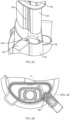
FIG. 2A is a detailed view of the feed chute ofFIG. 1 coupled to the linkage cover ofFIG. 1 according to some implementations; -
FIG. 2B is a detailed view of the pusher ofFIG. 1 according to some implementations; -
FIGS. 2C and 2D illustrate the interface between the feed chute and the pusher ofFIG. 1 according to some implementations; -
FIG. 3 illustrates the linkage mechanism of the food processor ofFIG. 1 according to some implementations; -
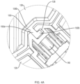
FIG. 4A shows a first configuration of the rib and the channel of the feed chute assembly ofFIG. 1 according to some implementations; and -
FIGS. 4B-D show a second configuration of the rib and the channel of the feed chute assembly ofFIG. 1 according to some implementations. - In the following description, like components have the same reference numerals, regardless of different illustrated implementations. To illustrate implementations clearly and concisely, the drawings may not necessarily reflect appropriate scale and may have certain features shown in somewhat schematic form. The disclosure may describe and/or illustrate features in one implementation, and in the same way or in a similar way in one or more other implementations, and/or combined with or instead of the features of the other implementations within the scope of the appended claims.
- In the specification and claims, for the purposes of describing and defining the invention, the terms "about" and "substantially" represent the inherent degree of uncertainty attributed to any quantitative comparison, value, measurement, or other representation. The terms "about" and "substantially" moreover represent the degree by which a quantitative representation may vary from a stated reference without resulting in a change in the basic function of the subject matter at issue. Open-ended terms, such as "comprise," "include," and/or plural forms of each, include the listed parts and can include additional parts not listed, while terms such as "and/or" include one or more of the listed parts and combinations of the listed parts. Use of the terms "top," "bottom," "above," "below" and the like helps only in the clear description of the disclosure and does not limit the structure, positioning and/or operation of the feed chute assembly in any manner.
-
FIG. 1 shows an implementation of afood processor 10 for use with thefeed chute assembly 100 of this disclosure. In some implementations, thefood processor 10 can generally comprise a base 12 housing a motor (not shown), anelectronic display 14, and acontainer 16. Thecontainer 16 may further comprise abowl 18 with ahandle 20. Thefeed chute assembly 100 includes alid 122, alinkage cover 130 and any of afirst pusher 128, and asecond pusher 132. Thelid 122 can removeably couple to afirst end 16a of thecontainer 16 while asecond end 16b of thecontainer 16 can removeably couple to thebase 12. Notably, thelid 122 does not function as a lid or cover for thefeed chute assembly 100, but rather as a lid or cover for thefood processor 10. Thelid 122 can comprise anintegral feed chute 126 for introducing food into thecontainer 16. Thefeed chute 126 may receive thefirst pusher 128 for guiding the food toward rotating blades (not shown) disposed near thefirst end 16a of thecontainer 16. Thelinkage cover 130 may communicate with thehandle 20, as further described below. In some implementations, thefirst pusher 128 can accommodate the smaller,second pusher 132. -
FIG. 2A shows an implementation of thefeed chute 126 of this disclosure coupled to thelinkage cover 130. As shown inFIG. 2A , thefeed chute 126 can have a substantially "D" shape. For example, thefeed chute 126 can comprise asidewall 134 having alinear portion 134a and acurved portion 134b. Thesidewall 134 furthermore defines aninner surface 136a and anouter surface 136b. Thelinkage cover 130 may couple to thecurved portion 134b of thesidewall 134. In some implementations, thelinkage cover 130 may have afirst portion 130a contacting theouter surface 136a of thesidewall 134 and asecond portion 130b, i.e., a guide housing, contacting theinner surface 136a of thesidewall 134. Thesecond portion 130b may define achannel 138 extending vertically along theinner surface 136a of thesidewall 134 between opposingangled sides 131a,b. Thechannel 138 may at least partially communicate with aroller 140 of a linkage component electronically connected to the motor through anopening 142 in thesidewall 134, as further described below. In some implementations, a length of thechannel 138 may be less than a full height of theinner surface 136a of thesidewall 134. When thechannel 138 does not extend for the full height of theinner surface 136a of thesidewall 134, the portion of theinner surface 136a located below thechannel 138 may be smooth, advantageously providing the user with an easy to clean surface. -
FIG. 2B shows an implementation of thefirst pusher 128 of this disclosure. Like thefeed chute 126, thefirst pusher 128 can have a substantially "D" shape for forming a close fit within thefeed chute 126. For example, thefirst pusher 128 can comprise asidewall 144 having a linear portion 144a and acurved portion 144b. Thesidewall 144 can furthermore define aninner surface 146a and anouter surface 146b. In some implementations, thefirst pusher 128 may include an upperperipheral rim 152 extending outward from thesidewall 144. A portion of theouter surface 146b of thecurved portion 144b defines arecess 148 with respect to a remainder of theouter surface 146b. In some implementations, therecess 148 can extend an entire height of thesidewall 144, as shown. Therecess 148 may be partially defined by opposingangled sides 148a,b corresponding to the opposingangled sides 131a,b of thesecond portion 130b of thelinkage cover 130. - Still referring to
FIG. 2B , in some implementations, arib 150 may extend along an entire height of therecess 148 without projecting beyond theouter surface 146b. However, the disclosure also contemplates that therib 150 may extend for less than an entire height of therecess 148. Thus, therecess 148 can advantageously provide a protected area to prevent damage to therib 150. In some implementations, therib 150 may be molded with thefirst pusher 128. However, the disclosure also contemplates that therib 150 could be molded separately and attached to thefirst pusher 128. Therecess 148 and therib 150 may be located on thefirst pusher 128 such that, when a user inserts thefirst pusher 128 into thefeed chute 126, therib 150 inserts into thechannel 138 of thelinkage cover 130, as shown inFIG. 2C . When the user at least partially inserts therib 150 into thechannel 138, therib 150 may operatively engage the roller of the linkage component (FIG. 2A ). When the user fully inserts therib 150 into thechannel 138, the upperperipheral rim 152 may cover apilot opening 154 of thechannel 138. As shown inFIG. 2D , this configuration of therib 150 and thechannel 138 may allow both therib 150 and thechannel 138 to reside within an inner perimeter P of thefeed chute 128. - As shown in
FIG. 3 , engagement of therib 150 with theroller 140 of thelinkage component 156 may cause theroller 140 to rotate about an arc and convert into linear vertical motion to activate a microswitch (not shown) of thefood processor 10 through anintermediate link 157 in thehandle 20. A microprocessor or printed circuit board (PCB) (not shown) in thebase 12 may sense the activation of the microswitch, thus allowing the motor to supply power to rotate the blades. If the motor is still running when the user removes thefirst pusher 128 from thefeed chute 126, the microprocessor or PCB may also sense a deactivation of the microswitch. Deactivation of the microswitch can stop the rotation of the blades within a short time frame - for example, less than 4 seconds. A biasing mechanism, such as a spring 160, may allow theroller 140 to return to its starting position when the user removes thefirst pusher 128 from thefeed chute 126. Advantageously, this safety mechanism may prevent the user from accessing the interior of thefeed chute 126 and blades while the motor rotates the blades. Moreover, the motor can only operate when the user at least partially inserts therib 150 into thechannel 138. - As shown in
FIG. 4A , implementations of therib 150 can have a shape selected to correspond to a shape of thechannel 138. For example, a cross-section of therib 150 may have an "L" shape, with astem portion 150a extending from theouter surface 136b of thefirst pusher 128 within therecess 148, and aleg portion 150b extending substantially transverse to thestem portion 150a. Likewise, a cross-section of thechannel 138 can have an L-shape to accommodate the L-shapedrib 150. The L-shaped configuration of therib 150 and thechannel 138 advantageously provides the user with a smooth motion as the user inserts thefirst pusher 128 into thefeed chute 126. In an alternative implementation, shown inFIGS. 4B-D , a cross-section of therib 150' may have a "wineglass" shape, with astem portion 150a' extending from theouter surface 136b of thefirst pusher 128 within therecess 148, and a symmetrically-angledportion 150b' for engaging theroller 140. Likewise, a cross-section of thechannel 138' may have a wineglass shape to accommodate the wineglass shapedrib 150'. The wineglass shaped configuration of therib 150' and thechannel 138' may advantageously provide a constant travel distance on thefirst pusher 128 to ensure that the microswitch is always pressed when thefirst pusher 128 reaches the same point inside thefeed chute 126. The disclosure also contemplates other suitable configurations of therib 150 and thechannel 138, such as a "T" or an "I" shape. - While the disclosure particularly shows and describes preferred implementations, those skilled in the art will understand that various changes in form and details may exist without departing from the scope of the invention as defined by the appended claims. The scope of this present application intends to cover such variations. As such, the foregoing description of implementations of the present application does not intend to limit the full scope conveyed by the appended claims.
Claims (15)
- A feed chute assembly (100) for a food processing system, the feed chute assembly comprising:a lid (122) coupleable to a first end of a container (16), the lid having a feed chute (126) for introducing food into the container, a sidewall of the feed chute (126) defining an inner and outer surface;a linkage cover (130) coupled to the feed chute (126), the linkage cover housing a linkage component (156) and defining a channel (138) within an inside perimeter of the feed chute (126), the channel (138) at least partially in communication with a portion of the linkage component (156) through an opening in the sidewall of the feed chute (126);a pusher (128) insertable into the feed chute (126), a portion of an outer surface (146b) of the pusher defining a recess (148) with respect to a remainder of the outer surface of the pusher (128); anda rib (150) disposed within the recess (148), the rib (150) configured for insertion into the channel (138) of the linkage cover (130) such that, when the rib (150) is at least partially inserted into the channel (138), the rib (150) operatively engages the portion of the linkage component (156).
- The feed chute assembly of claim 1, wherein the linkage cover (130) comprises:a first portion (130a) contacting the outer surface of the feed chute (126), the first portion housing the linkage component; anda second portion (130b) contacting the inner surface of the feed chute (126), the second portion defining the channel extending vertically along the inner surface of the feed chute (126).
- The feed chute assembly of claim 2, wherein the second portion (130b) comprises a guide housing extending from the inner surface of the sidewall (134) within the inside perimeter, the guide housing extending into the recess when the pusher (128) is inserted into the feed chute (126).
- The feed chute assembly of any of claims 1-3, wherein a shape of the rib (150) corresponds to a shape of the channel (138).
- The feed chute assembly of any of claims 1-4, wherein a cross section of the rib (150) has one of an L-shape, T-shape, I-shape, and a wineglass shape.
- The feed chute assembly of any of claims 1-5, wherein a length of the channel (138) is less than a height of the inner surface of the feed chute (126).
- The feed chute assembly of any of claims 1-6, wherein a portion of the inner surface of the feed chute (126) located below the channel provides an easy to clean surface.
- The feed chute assembly of any of claims 1-7, wherein the food processing system further comprises a base (12) housing a motor, and wherein the container (16) has a second end (16b) removeably coupleable to the base (12).
- The feed chute assembly of claim 8, wherein the portion of the linkage component (156) is a roller operatively connected to a linkage system for activating the motor.
- The feed chute assembly of claim 8, wherein the motor can only operate when the rib (150) is at least partially inserted into the channel (138).
- The feed chute assembly of any of claims 1-10, wherein the pusher (128) includes an upper peripheral rim (152) extending outward from the sidewall (144), and wherein, when the pusher (128) is fully inserted into the feed chute (126), the upper peripheral rim (152) covers a pilot opening (154) of the channel (138).
- The feed chute assembly of any of claims 1-11, wherein the pusher (128) is configured to accommodate a second and smaller pusher (132).
- A method of operating a feed chute assembly (100) of a food processing system, the method comprising:inserting a pusher (128) into a feed chute (126) of a lid (122) coupled to a first end of a container (16), a sidewall of the feed chute (126) defining an inner and outer surface, a linkage cover (130) coupled to the feed chute (126), the linkage cover (130) housing a linkage component (156) and defining a channel (138) within an inside perimeter of the feed chute, the channel (138) at least partially in communication with a portion of the linkage component (156) through an opening (142) in the sidewall (134) of the feed chute (126), a portion of an outer surface (146b) of the pusher defining a recess (148) with respect to a remainder of the outer surface of the pusher (128), a rib (150) disposed within the recess (148);wherein, in response to the inserting of the pusher (128), the rib (148) at least partially inserts into the channel (138) of the linkage cover (130) such that the rib (150) engages the portion of the linkage component (156).
- The method of claim 13, wherein the linkage cover (130) comprises:a first portion (130a) contacting the outer surface of the feed chute, the first portion housing the linkage component; anda second portion (130b) contacting the inner surface of the feed chute, the second portion defining the channel extending vertically along the inner surface of the feed chute.
- The method of claim 14, wherein the second portion (130b) comprises a guide housing extending from the inner surface of the sidewall within the inside perimeter, the guide housing extending into the recess (148) when the pusher (128) is inserted into the feed chute (126).
Applications Claiming Priority (1)
| Application Number | Priority Date | Filing Date | Title |
|---|---|---|---|
| US17/684,505 US20230277002A1 (en) | 2022-03-02 | 2022-03-02 | Feed chute assembly for a food processor |
Publications (2)
| Publication Number | Publication Date |
|---|---|
| EP4238463A1 EP4238463A1 (en) | 2023-09-06 |
| EP4238463B1 true EP4238463B1 (en) | 2024-11-20 |
Family
ID=82846222
Family Applications (1)
| Application Number | Title | Priority Date | Filing Date |
|---|---|---|---|
| EP22188899.3A Active EP4238463B1 (en) | 2022-03-02 | 2022-08-04 | Feed chute assembly for a food processor |
Country Status (6)
| Country | Link |
|---|---|
| US (1) | US20230277002A1 (en) |
| EP (1) | EP4238463B1 (en) |
| CN (2) | CN116725400A (en) |
| CA (1) | CA3169267A1 (en) |
| DE (1) | DE202022104823U1 (en) |
| WO (1) | WO2023167704A1 (en) |
Families Citing this family (1)
| Publication number | Priority date | Publication date | Assignee | Title |
|---|---|---|---|---|
| US20230277002A1 (en) * | 2022-03-02 | 2023-09-07 | Sharkninja Operating Llc | Feed chute assembly for a food processor |
Family Cites Families (13)
| Publication number | Priority date | Publication date | Assignee | Title |
|---|---|---|---|---|
| FR2824251B1 (en) * | 2001-05-02 | 2003-06-27 | Hameur | SAFETY DEVICE FOR A LARGE CHUTE KITCHEN ROBOT |
| EP1486121A3 (en) * | 2003-06-10 | 2008-09-17 | Werner & Pfleiderer Lebensmitteltechnik GmbH | Feeding device for a baking oven and baking plant comprising such a feeding device and a baking oven. |
| FR2920659B1 (en) * | 2007-09-10 | 2009-10-09 | Seb Sa | CULINARY PREPARATION ELECTRICAL APPLIANCE COMPRISING A COVER COMPRISING A FOOD CHIMNEY WITH A TWO-PART PUSH-BUTTON |
| US8262005B2 (en) * | 2009-09-08 | 2012-09-11 | Wal-Mart Stores, Inc. | Processing apparatus and method |
| US9386884B2 (en) * | 2010-12-07 | 2016-07-12 | Breville Pty Limited | Food processor |
| US9770135B2 (en) * | 2013-09-04 | 2017-09-26 | Breville Pty Ltd | Food processor with safety mechanism |
| CN201922224U (en) * | 2010-12-09 | 2011-08-10 | 广州柴油机厂股份有限公司 | Special tool for mounting and detaching connecting rod cover of diesel engine |
| JP2014171626A (en) * | 2013-03-08 | 2014-09-22 | Panasonic Corp | Rice cooker |
| CN203436142U (en) * | 2013-07-31 | 2014-02-19 | 惠阳亚伦塑胶电器实业有限公司 | Juice extractor |
| US9924838B2 (en) * | 2014-07-03 | 2018-03-27 | Sharkninja Operations Llc | Food processing apparatus and method |
| US10604308B2 (en) * | 2018-04-05 | 2020-03-31 | Joel Harris | Multi-function container lid |
| US20200253424A1 (en) * | 2019-02-13 | 2020-08-13 | Hamilton Beach Brands, Inc. | Food Processor With Spiralizing Accessory |
| US20230277002A1 (en) * | 2022-03-02 | 2023-09-07 | Sharkninja Operating Llc | Feed chute assembly for a food processor |
-
2022
- 2022-03-02 US US17/684,505 patent/US20230277002A1/en active Pending
- 2022-07-21 WO PCT/US2022/037912 patent/WO2023167704A1/en not_active Ceased
- 2022-07-27 CA CA3169267A patent/CA3169267A1/en active Pending
- 2022-08-04 EP EP22188899.3A patent/EP4238463B1/en active Active
- 2022-08-26 DE DE202022104823.1U patent/DE202022104823U1/en active Active
- 2022-08-26 CN CN202211030383.8A patent/CN116725400A/en active Pending
- 2022-08-26 CN CN202222255990.6U patent/CN218784397U/en active Active
Also Published As
| Publication number | Publication date |
|---|---|
| EP4238463A1 (en) | 2023-09-06 |
| CA3169267A1 (en) | 2023-09-02 |
| CN116725400A (en) | 2023-09-12 |
| DE202022104823U1 (en) | 2022-09-26 |
| US20230277002A1 (en) | 2023-09-07 |
| WO2023167704A1 (en) | 2023-09-07 |
| CN218784397U (en) | 2023-04-04 |
Similar Documents
| Publication | Publication Date | Title |
|---|---|---|
| US8220730B2 (en) | Interlock system | |
| US4396159A (en) | Protective guide structure for preventing inadvertent actuation of a food processor with a tilted cover | |
| US20210113023A1 (en) | Food processor lid | |
| US9084508B2 (en) | Kitchen appliance for processing foodstuff and method of operating same | |
| US7520453B2 (en) | Safety actuator for a food processor having a visual indication | |
| CZ20011237A3 (en) | Safety system for food processing apparatus | |
| US9198540B2 (en) | Food processor with locking bail handle | |
| US20040042337A1 (en) | Food processors | |
| US5129589A (en) | Table-top multi-purpose device driven by means of an immersion blender | |
| EP4238463A1 (en) | Feed chute assembly for a food processor | |
| US5486665A (en) | Safety switch for a food processor | |
| CN218922352U (en) | Adjustable blade assembly for food processing system | |
| US6474578B1 (en) | Safety device for food processor | |
| US6209810B1 (en) | Electrical household appliance for preparing food comprising a safety device | |
| CN100528055C (en) | Safety switch for kitchen utensils | |
| US12279717B2 (en) | Blender | |
| EP4014821A1 (en) | Blender | |
| WO2003051587A1 (en) | Box with a slicer for cheese and food | |
| JPS6137376Y2 (en) | ||
| JPS59174124A (en) | electric cooker | |
| JPS6121081B2 (en) | ||
| MXPA99006333A (en) | Safety system to prevent the operation of a blender or food processor if the cover of this is not placed in your life | |
| JPS6147088B2 (en) |
Legal Events
| Date | Code | Title | Description |
|---|---|---|---|
| PUAI | Public reference made under article 153(3) epc to a published international application that has entered the european phase |
Free format text: ORIGINAL CODE: 0009012 |
|
| STAA | Information on the status of an ep patent application or granted ep patent |
Free format text: STATUS: REQUEST FOR EXAMINATION WAS MADE |
|
| 17P | Request for examination filed |
Effective date: 20220804 |
|
| AK | Designated contracting states |
Kind code of ref document: A1 Designated state(s): AL AT BE BG CH CY CZ DE DK EE ES FI FR GB GR HR HU IE IS IT LI LT LU LV MC MK MT NL NO PL PT RO RS SE SI SK SM TR |
|
| GRAP | Despatch of communication of intention to grant a patent |
Free format text: ORIGINAL CODE: EPIDOSNIGR1 |
|
| STAA | Information on the status of an ep patent application or granted ep patent |
Free format text: STATUS: GRANT OF PATENT IS INTENDED |
|
| INTG | Intention to grant announced |
Effective date: 20240909 |
|
| GRAS | Grant fee paid |
Free format text: ORIGINAL CODE: EPIDOSNIGR3 |
|
| GRAA | (expected) grant |
Free format text: ORIGINAL CODE: 0009210 |
|
| STAA | Information on the status of an ep patent application or granted ep patent |
Free format text: STATUS: THE PATENT HAS BEEN GRANTED |
|
| AK | Designated contracting states |
Kind code of ref document: B1 Designated state(s): AL AT BE BG CH CY CZ DE DK EE ES FI FR GB GR HR HU IE IS IT LI LT LU LV MC MK MT NL NO PL PT RO RS SE SI SK SM TR |
|
| REG | Reference to a national code |
Ref country code: GB Ref legal event code: FG4D |
|
| REG | Reference to a national code |
Ref country code: CH Ref legal event code: EP |
|
| REG | Reference to a national code |
Ref country code: DE Ref legal event code: R096 Ref document number: 602022007852 Country of ref document: DE |
|
| REG | Reference to a national code |
Ref country code: IE Ref legal event code: FG4D |
|
| P01 | Opt-out of the competence of the unified patent court (upc) registered |
Free format text: CASE NUMBER: APP_62140/2024 Effective date: 20241121 |
|
| REG | Reference to a national code |
Ref country code: LT Ref legal event code: MG9D |
|
| REG | Reference to a national code |
Ref country code: NL Ref legal event code: MP Effective date: 20241120 |
|
| PG25 | Lapsed in a contracting state [announced via postgrant information from national office to epo] |
Ref country code: IS Free format text: LAPSE BECAUSE OF FAILURE TO SUBMIT A TRANSLATION OF THE DESCRIPTION OR TO PAY THE FEE WITHIN THE PRESCRIBED TIME-LIMIT Effective date: 20250320 Ref country code: PT Free format text: LAPSE BECAUSE OF FAILURE TO SUBMIT A TRANSLATION OF THE DESCRIPTION OR TO PAY THE FEE WITHIN THE PRESCRIBED TIME-LIMIT Effective date: 20250320 Ref country code: HR Free format text: LAPSE BECAUSE OF FAILURE TO SUBMIT A TRANSLATION OF THE DESCRIPTION OR TO PAY THE FEE WITHIN THE PRESCRIBED TIME-LIMIT Effective date: 20241120 |
|
| PG25 | Lapsed in a contracting state [announced via postgrant information from national office to epo] |
Ref country code: NL Free format text: LAPSE BECAUSE OF FAILURE TO SUBMIT A TRANSLATION OF THE DESCRIPTION OR TO PAY THE FEE WITHIN THE PRESCRIBED TIME-LIMIT Effective date: 20241120 Ref country code: FI Free format text: LAPSE BECAUSE OF FAILURE TO SUBMIT A TRANSLATION OF THE DESCRIPTION OR TO PAY THE FEE WITHIN THE PRESCRIBED TIME-LIMIT Effective date: 20241120 |
|
| REG | Reference to a national code |
Ref country code: AT Ref legal event code: MK05 Ref document number: 1742764 Country of ref document: AT Kind code of ref document: T Effective date: 20241120 |
|
| PG25 | Lapsed in a contracting state [announced via postgrant information from national office to epo] |
Ref country code: BG Free format text: LAPSE BECAUSE OF FAILURE TO SUBMIT A TRANSLATION OF THE DESCRIPTION OR TO PAY THE FEE WITHIN THE PRESCRIBED TIME-LIMIT Effective date: 20241120 |
|
| PG25 | Lapsed in a contracting state [announced via postgrant information from national office to epo] |
Ref country code: ES Free format text: LAPSE BECAUSE OF FAILURE TO SUBMIT A TRANSLATION OF THE DESCRIPTION OR TO PAY THE FEE WITHIN THE PRESCRIBED TIME-LIMIT Effective date: 20241120 |
|
| PG25 | Lapsed in a contracting state [announced via postgrant information from national office to epo] |
Ref country code: NO Free format text: LAPSE BECAUSE OF FAILURE TO SUBMIT A TRANSLATION OF THE DESCRIPTION OR TO PAY THE FEE WITHIN THE PRESCRIBED TIME-LIMIT Effective date: 20250220 |
|
| PG25 | Lapsed in a contracting state [announced via postgrant information from national office to epo] |
Ref country code: GR Free format text: LAPSE BECAUSE OF FAILURE TO SUBMIT A TRANSLATION OF THE DESCRIPTION OR TO PAY THE FEE WITHIN THE PRESCRIBED TIME-LIMIT Effective date: 20250221 Ref country code: AT Free format text: LAPSE BECAUSE OF FAILURE TO SUBMIT A TRANSLATION OF THE DESCRIPTION OR TO PAY THE FEE WITHIN THE PRESCRIBED TIME-LIMIT Effective date: 20241120 Ref country code: LV Free format text: LAPSE BECAUSE OF FAILURE TO SUBMIT A TRANSLATION OF THE DESCRIPTION OR TO PAY THE FEE WITHIN THE PRESCRIBED TIME-LIMIT Effective date: 20241120 |
|
| PG25 | Lapsed in a contracting state [announced via postgrant information from national office to epo] |
Ref country code: PL Free format text: LAPSE BECAUSE OF FAILURE TO SUBMIT A TRANSLATION OF THE DESCRIPTION OR TO PAY THE FEE WITHIN THE PRESCRIBED TIME-LIMIT Effective date: 20241120 |
|
| PG25 | Lapsed in a contracting state [announced via postgrant information from national office to epo] |
Ref country code: RS Free format text: LAPSE BECAUSE OF FAILURE TO SUBMIT A TRANSLATION OF THE DESCRIPTION OR TO PAY THE FEE WITHIN THE PRESCRIBED TIME-LIMIT Effective date: 20250220 |
|
| PG25 | Lapsed in a contracting state [announced via postgrant information from national office to epo] |
Ref country code: SM Free format text: LAPSE BECAUSE OF FAILURE TO SUBMIT A TRANSLATION OF THE DESCRIPTION OR TO PAY THE FEE WITHIN THE PRESCRIBED TIME-LIMIT Effective date: 20241120 |
|
| PG25 | Lapsed in a contracting state [announced via postgrant information from national office to epo] |
Ref country code: DK Free format text: LAPSE BECAUSE OF FAILURE TO SUBMIT A TRANSLATION OF THE DESCRIPTION OR TO PAY THE FEE WITHIN THE PRESCRIBED TIME-LIMIT Effective date: 20241120 |
|
| PG25 | Lapsed in a contracting state [announced via postgrant information from national office to epo] |
Ref country code: EE Free format text: LAPSE BECAUSE OF FAILURE TO SUBMIT A TRANSLATION OF THE DESCRIPTION OR TO PAY THE FEE WITHIN THE PRESCRIBED TIME-LIMIT Effective date: 20241120 |
|
| PGFP | Annual fee paid to national office [announced via postgrant information from national office to epo] |
Ref country code: FR Payment date: 20250610 Year of fee payment: 4 |
|
| PG25 | Lapsed in a contracting state [announced via postgrant information from national office to epo] |
Ref country code: RO Free format text: LAPSE BECAUSE OF FAILURE TO SUBMIT A TRANSLATION OF THE DESCRIPTION OR TO PAY THE FEE WITHIN THE PRESCRIBED TIME-LIMIT Effective date: 20241120 |
|
| PG25 | Lapsed in a contracting state [announced via postgrant information from national office to epo] |
Ref country code: SK Free format text: LAPSE BECAUSE OF FAILURE TO SUBMIT A TRANSLATION OF THE DESCRIPTION OR TO PAY THE FEE WITHIN THE PRESCRIBED TIME-LIMIT Effective date: 20241120 |
|
| PG25 | Lapsed in a contracting state [announced via postgrant information from national office to epo] |
Ref country code: CZ Free format text: LAPSE BECAUSE OF FAILURE TO SUBMIT A TRANSLATION OF THE DESCRIPTION OR TO PAY THE FEE WITHIN THE PRESCRIBED TIME-LIMIT Effective date: 20241120 |
|
| PG25 | Lapsed in a contracting state [announced via postgrant information from national office to epo] |
Ref country code: IT Free format text: LAPSE BECAUSE OF FAILURE TO SUBMIT A TRANSLATION OF THE DESCRIPTION OR TO PAY THE FEE WITHIN THE PRESCRIBED TIME-LIMIT Effective date: 20241120 |
|
| REG | Reference to a national code |
Ref country code: DE Ref legal event code: R097 Ref document number: 602022007852 Country of ref document: DE |
|
| PG25 | Lapsed in a contracting state [announced via postgrant information from national office to epo] |
Ref country code: SE Free format text: LAPSE BECAUSE OF FAILURE TO SUBMIT A TRANSLATION OF THE DESCRIPTION OR TO PAY THE FEE WITHIN THE PRESCRIBED TIME-LIMIT Effective date: 20241120 |
|
| PLBE | No opposition filed within time limit |
Free format text: ORIGINAL CODE: 0009261 |
|
| STAA | Information on the status of an ep patent application or granted ep patent |
Free format text: STATUS: NO OPPOSITION FILED WITHIN TIME LIMIT |
|
| PGFP | Annual fee paid to national office [announced via postgrant information from national office to epo] |
Ref country code: DE Payment date: 20250611 Year of fee payment: 4 |
|
| 26N | No opposition filed |
Effective date: 20250821 |
|
| REG | Reference to a national code |
Ref country code: CH Ref legal event code: H13 Free format text: ST27 STATUS EVENT CODE: U-0-0-H10-H13 (AS PROVIDED BY THE NATIONAL OFFICE) Effective date: 20260324 |
|
| PG25 | Lapsed in a contracting state [announced via postgrant information from national office to epo] |
Ref country code: MC Free format text: LAPSE BECAUSE OF FAILURE TO SUBMIT A TRANSLATION OF THE DESCRIPTION OR TO PAY THE FEE WITHIN THE PRESCRIBED TIME-LIMIT Effective date: 20241120 |
|
| PG25 | Lapsed in a contracting state [announced via postgrant information from national office to epo] |
Ref country code: LU Free format text: LAPSE BECAUSE OF NON-PAYMENT OF DUE FEES Effective date: 20250804 |
|
| PG25 | Lapsed in a contracting state [announced via postgrant information from national office to epo] |
Ref country code: CH Free format text: LAPSE BECAUSE OF NON-PAYMENT OF DUE FEES Effective date: 20250831 |