EP4238303B1 - A multiperspective photography camera device - Google Patents
A multiperspective photography camera device Download PDFInfo
- Publication number
- EP4238303B1 EP4238303B1 EP21801885.1A EP21801885A EP4238303B1 EP 4238303 B1 EP4238303 B1 EP 4238303B1 EP 21801885 A EP21801885 A EP 21801885A EP 4238303 B1 EP4238303 B1 EP 4238303B1
- Authority
- EP
- European Patent Office
- Prior art keywords
- multiperspective
- camera device
- photography camera
- lens
- lens array
- Prior art date
- Legal status (The legal status is an assumption and is not a legal conclusion. Google has not performed a legal analysis and makes no representation as to the accuracy of the status listed.)
- Active
Links
Images




Classifications
-
- H—ELECTRICITY
- H04—ELECTRIC COMMUNICATION TECHNIQUE
- H04N—PICTORIAL COMMUNICATION, e.g. TELEVISION
- H04N23/00—Cameras or camera modules comprising electronic image sensors; Control thereof
- H04N23/95—Computational photography systems, e.g. light-field imaging systems
- H04N23/957—Light-field or plenoptic cameras or camera modules
-
- G—PHYSICS
- G02—OPTICS
- G02B—OPTICAL ELEMENTS, SYSTEMS OR APPARATUS
- G02B3/00—Simple or compound lenses
- G02B3/0006—Arrays
- G02B3/0037—Arrays characterized by the distribution or form of lenses
- G02B3/005—Arrays characterized by the distribution or form of lenses arranged along a single direction only, e.g. lenticular sheets
-
- G—PHYSICS
- G06—COMPUTING OR CALCULATING; COUNTING
- G06T—IMAGE DATA PROCESSING OR GENERATION, IN GENERAL
- G06T7/00—Image analysis
- G06T7/50—Depth or shape recovery
-
- H—ELECTRICITY
- H04—ELECTRIC COMMUNICATION TECHNIQUE
- H04N—PICTORIAL COMMUNICATION, e.g. TELEVISION
- H04N23/00—Cameras or camera modules comprising electronic image sensors; Control thereof
- H04N23/50—Constructional details
- H04N23/51—Housings
-
- H—ELECTRICITY
- H04—ELECTRIC COMMUNICATION TECHNIQUE
- H04N—PICTORIAL COMMUNICATION, e.g. TELEVISION
- H04N23/00—Cameras or camera modules comprising electronic image sensors; Control thereof
- H04N23/50—Constructional details
- H04N23/55—Optical parts specially adapted for electronic image sensors; Mounting thereof
-
- G—PHYSICS
- G02—OPTICS
- G02B—OPTICAL ELEMENTS, SYSTEMS OR APPARATUS
- G02B27/00—Optical systems or apparatus not provided for by any of the groups G02B1/00 - G02B26/00, G02B30/00
- G02B27/0075—Optical systems or apparatus not provided for by any of the groups G02B1/00 - G02B26/00, G02B30/00 with means for altering, e.g. increasing, the depth of field or depth of focus
-
- G—PHYSICS
- G06—COMPUTING OR CALCULATING; COUNTING
- G06T—IMAGE DATA PROCESSING OR GENERATION, IN GENERAL
- G06T2207/00—Indexing scheme for image analysis or image enhancement
- G06T2207/10—Image acquisition modality
- G06T2207/10028—Range image; Depth image; 3D point clouds
Definitions
- the present invention generally relates to a multiperspective photography camera device, and more specifically to a multiperspective photography camera device made to provide directly and simultaneously, i.e. with a single shot, a set of high resolution images with different perspectives of a macroscopic 3D scene, along a high field of view.
- a 3D scene emits a field of light rays that carries information on the spatial coordinates (x, y, z) of the light-emitting points, and also angular information ( ⁇ , ⁇ ) associated to the inclination of each ray. If one considers light fields that basically propagate in the z direction, to characterize said field of light rays, the spatial coordinates (x, y) in any plane perpendicular to said z direction are enough.
- L The four-dimensional function, L (x, y; ⁇ , ⁇ ), which describes the radiance of the field of light rays in a plane perpendicular to the direction of propagation of the field, is called the plenoptic function or also lightfield function [1].
- Conventional photographic cameras basically consist of a photographic objective and an irradiance sensor.
- the photographic objective can have very complex designs.
- basically a photographic objective is composed of a lens (or a set of lenses aligned with the same optical axis) that provides the image of the object on the irradiance sensor, and of a diaphragm that limits the aperture of the system.
- the irradiance sensor is composed of a photosensitive pixel array. Each pixel integrates the radiance of all the rays reaching the same, coming from a point of the object.
- the set of pixels constitutes a two-dimensional photograph of the scene. Said 2D photograph contains spatial information of the scene, but has lost all the angular information contained in the rays emitted by the scene, as shown Fig. 2 .
- the plenoptic camera or lightfield camera.
- the design of this camera is based on inserting a microlenses array on the image plane of the conventional photography camera and moving the sensor to the conjugate plane, through the microlenses, with the aperture diaphragm, as shown in Fig. 3 .
- the plenoptic camera allows capturing the angular information of the light rays emitted by the sample. From the information contained in a plenoptic image it is possible to: (a) calculate a set of images with different perspectives; (b) compute a stack of refocused images at different depths; and (c) computing a depth map of the 3D scene.
- this design of the plenoptic camera has some essential disadvantages: (a) It does not directly capture perspective images, but the perspectives are obtained after a computational pixel-mapping process; (b) Perspective images have a very poor spatial resolution (about 100 times worse than a conventional photograph); (c) The refocused images after a computational process also have very poor spatial resolution; also (d) The refocused images have a heterogeneous spatial resolution (each refocusing plane has its own spatial resolution); (e) The number of refocusing planes of the 3D scene is very low; and (f) The spatial resolution of the depth map is also very poor.
- One of those devices is disclosed in CN111487759A , and is a multi-aperture imaging endoscopic system composed by a bitelecentric arrangement, a microlens array placed just behind the bitelecentric arrangement and a sensor at the focal plane of the microlenses. It is designed for collecting the parallel rays emerging from an endoscope.
- the main aim of that system is to avoid the crosstalk between perspective images provided by an endoscope. Since the microlenses are not at the plane conjugated with the aperture stop, the system provides images that are not free from the vignetting.
- This system cannot be used as multiperspective photography camera because it has no photography objective, and therefore cannot provide image of real objects, since those objects do not provide parallel rays, but diverging rays. Besides, in that case, the crosstalk is not avoided.
- This system cannot be attached to a photography objective, because photography objectives do no provide parallel rays, but strongly converging rays.
- WO/2020/030841A1 discloses a plenoptic ocular device composed by an external aperture stop, a non-telecentric doublet, which behaves as a conventional eyepiece, a microlens array and a CCD-type sensor.
- This device is designed for collecting the rays which, emitted by close microscopic objects and refracted through the microscope objective, emerge from the microscope tube lens.
- the plenoptic ocular captures the light emitted by the intermediate image provided by the tube lens, which is just at the external aperture stop.
- This device cannot be used for conventional photography, since it cannot provide multiperspective images of macroscopic objects that are far from the device.
- X. Jiang et al. discloses a light field microscope including an imaging plenoptic camera that is based on placing a microlens array in the image plane of a conventional microscope.
- a set of orthographic perspective images can be calculated from the plenoptic image, and from them a stack of refocused images. It is also possible to calculate a depth map.
- Its advantage over the stereoscopic camera is that it is a monocular camera and that it can resolve occlusions. Its main problem is the low resolution of the perspective images, and therefore of the refocused images and the depth map. Furthermore, the resolution is heterogeneous and not axially dense.
- M. Martinez-Corral et al. discloses an integral microscope that is composed exclusively of a microscope objective, telecentric arrangement, a microlenses array, located at the Fourier plane, and a CCD-type sensor. It provides multiperspective images from microscopic samples placed at the front focal plane of the microscope objective. This device cannot be used as a multi perspective photography camera because it is prepared to collect only the strongly diverging rays emitted by microscopic object placed very close to the device.
- the present invention relates to a multiperspective photography camera device, for capturing perspective images of a macroscopic 3D scene, comprising:
- the multiperspective photography camera device proposed by the present invention further comprises, housed within and attached to the hollow casing:
- the lens array is configured and arranged to be placed at a conjugate plane of the aperture diaphragm of the photographic objective, so that the lens array is arranged to simultaneously receive and simultaneously transmit to the photosensitive pixel array sensor light representative of a plurality of different perspectives of the macroscopic 3D scene, one perspective per array lens.
- a set of images with different perspectives of the macroscopic 3D scene can be directly acquired by the photosensitive pixel array sensor with a single camera shot.
- the multi perspective photography camera device of the present invention further comprises the above mentioned photographic objective housed within and attached to the hollow housing, and arranged behind the front opening so that light coming from the 3D scene passes first through the front opening, then through the photographic objective, then through the at least one converging lens and then through the lens array to impinge on the photosensitive pixel array sensor.
- the multiperspective photography camera device of the present invention further comprises the above mentioned photosensitive pixel array sensor housed within and attached to the hollow housing, and arranged behind said lens array at a distance coincident with the focal distance f ML of the lenses of the lens array, wherein the photosensitive pixel array sensor comprises several groups of photosensitive elements, each group comprising a plurality of photosensitive elements facing a respective lens of the lens array to sense light of a respective perspective image of the 3D scene.
- the multiperspective photography camera device constitutes a whole multiperspective photography camera, which preferably comprises other conventional optic devices included in photography cameras (such as a camera shutter), which have not been described in the present document not to obscure the description of the innovative components of the present invention.
- each of said pluralities of photosensitive elements comprises at least 10,000 photosensitive elements, distributed for example in the form of a 100 ⁇ 100 two-dimensional square or hexagonal array.
- each lens of the lens array has an area of 1 mm 2 and each photosensitive element, i.e. each pixel, of the photosensitive pixel array sensor has an area of 0.000010 mm 2
- each plurality of photosensitive elements comprises about 100,000 photosensitive elements (pixels), exactly 102,400 if the plurality of photosensitive elements is in the form of a 320 ⁇ 320 two-dimensional square array.
- the hollow casing further comprises a back opening for the exit of light coming from the lens array, and a back coupling arrangement for coupling the hollow casing to a camera body housing the photosensitive pixel array sensor, such that the back opening is optically communicated and aligned with an opening of said camera body and the lens array is distanced from the photosensitive pixel array sensor a distance coincident with the focal distance f ML of the lenses of the lens array.
- the multiperspective photography camera device of the present invention further comprises the above mentioned photographic objective housed within and attached to the hollow housing, and arranged behind the front opening so that light coming from the 3D scene passes first through the front opening, then through the photographic objective, then through the at least one converging lens and then through the lens array to impinge on the photosensitive pixel array sensor.
- the multiperspective photography camera device does not constitute a whole multiperspective photography camera, as it lacks the photosensitive pixel array sensor, but a module to be coupled to the above mentioned camera body that houses the photosensitive pixel array sensor, so that a photographic camera is built.
- the multiperspective photography camera device of the present invention further comprises a front coupling arrangement for coupling the hollow casing to said photographic objective, such that the front opening of the hollow casing is optically communicated and aligned with the photographic objective and the requested value of z ob ′ is achieved.
- the multiperspective photography camera device does not either constitute a whole multiperspective photography camera, as it lacks the photographic objective and the photosensitive pixel array sensor, but a module to be intercoupled between an external photographic objective and the above mentioned camera body that houses the photosensitive pixel array sensor, so that a multiperspective photography camera is built.
- the multiperspective photography camera device of the present invention further comprises a front separation distance adjustment mechanism to adjust the separation distance between the photographic objective and the field diaphragm so that the requested value of z ob ′ is achieved.
- a front separation distance adjustment mechanism is not included, as that separation distance is factory set.
- the multiperspective photography camera device of the present invention further comprises a back separation distance adjustment mechanism to adjust the separation distance between the at least one converging lens and the lens array so that the requested value of z R ′ is achieved.
- a back separation distance adjustment mechanism is not included, as that separation distance is factory set.
- the lenses of the lens array are equidistantly separated a distance p between the centres of each two contiguous lenses.
- the lens array of the multiperspective photography camera device of the present invention is a J ⁇ J two-dimensional lens array, where preferably J ⁇ 5.
- the multi perspective photography camera device of the present invention further comprises, for an embodiment, processing means operatively connected to the photosensitive pixel array sensor to receive output signals and process output signals coming therefrom and being representative of the plurality of different perspectives of the 3D scene.
- the multiperspective photography camera device of the present invention further comprises communication means operatively connected to the photosensitive pixel array sensor to receive therefrom output signals being representative of the plurality of different perspectives of the 3D scene, and being configured to transmit the received output signals to remote processing means configured to process said output signals.
- the above mentioned processing means and/or remote processing means are configured to perform at least one of the following tasks, for static and dynamic scenes, by processing the received output signals: 3D image reconstruction of non-occluded and occluded objects, generation of depth maps, and ballistic photon signal strengthening.
- the multiperspective photography camera device of the present invention constitutes a passive device configured to operate under ambient light.
- the multiperspective photography camera device proposed by the present invention can be also used to capture 3D videos of the 3D scene, or a sequence of consecutive 3D photographs.
- the present invention allows the simultaneous capture of an array of elemental/perspective images (that is, of photographs from different perspectives) with high resolution of macroscopic 3D scenes.
- This set of elemental/perspective images allows, for both static and dynamic scenes, the calculation of stacks of high-resolution refocused images at different depths. In other words, it enables high-resolution refocusing a posteriori. This ability to refocus has the additional advantage that it can be carried out even in partially occluded scenes, since to reconstruct an occluded part it is enough that it is visible to at least one of the elemental/perspective images.
- Another advantage comes from the ability of multiperspective systems to reinforce the signal of ballistic photons, compared to those that suffer from scattering. This enables the invention to obtain refocused images and depth maps in cloudy environments, such as the case where the 3D scene is located in a smoky or foggy environment.
- An additional application from the depth map is the computation of images for its display on auto-stereoscopic 3D monitors.
- the use of the device of the present invention allows to capture the 3D structure of near and distant scenes, operating with ambient light and even in unfavorable conditions, such as an environment with fog, smoke, or other diffusive elements. This allows passive 3D metrology and variable environments.
- first, second and third working embodiments show a multiperspective photography camera device comprising:
- the lens array 8 is configured and arranged to be placed at a conjugate plane of said aperture diaphragm 2 of the photographic objective OB, so that the lens array 8 is arranged to simultaneously receive and simultaneously transmit to the photosensitive pixel array sensor 9 light representative of a plurality of different perspectives of the 3D scene S, one perspective per array lens.
- the multiperspective photography camera device is a whole photography camera.
- Two essential conjugation relationships can be seen in the scheme shown in that figure, namely: (a) The object plane OP is conjugated with the field diaphragm 5, and this with the photosensitive pixel array sensor 9; (b) The aperture diaphragm 2 of the photographic objective OB is conjugated with the lens array 8. If one looks at the path of the central light rays, one can see that each lens of the lens array 8 provides a different image of the 3D object S to the photosensitive pixel array sensor 9. Each lens "sees" the object S from a different perspective. For this reason, these images are called perspective images, or also elemental images.
- the angle ⁇ max formed by the central light rays corresponding to the outermost lenses of the lens array 8 defines the maximum difference in perspective angle, and is called the angle of maximum parallax.
- the multi perspective camera provides directly, and with a single shot, a set of images with different perspective of the 3D scene.
- the multiperspective photography camera there illustrated comprises a hollow casing which, for the illustrated embodiment, is formed by a front hollow casing portion 10a and a back hollow casing portion 10b, coupled to each other, but for non-illustrated embodiments is formed by a single-piece hollow casing.
- the photography camera of Figure 4 comprises the following components housed within and attached to the front hollow casing portion 10a:
- the multi perspective photography camera further comprises the following components, but not housed within front hollow casing 10a:
- J ⁇ J The number of elemental images J ⁇ J depends on the value of p .
- the higher the value of J the greater the number of perspectives captured and therefore the higher the angular resolution.
- a high value of J results in elemental images made up of few pixels. To obtain a good compromise between spatial and angular resolution, it is recommended to implement the device so that J ⁇ 5.
- f # EI The f -number associated with each elemental image, f # EI , is obtained by multiplying the f-number of the photographic objective, f # , by J .
- f # f ob / ⁇ A
- f # EI J ⁇ f # .
- a photographic camera focused at the hyperfocal distance, a H provides sharp images for objects located between a H /2 to infinity.
- ⁇ max is the angle subtended by the aperture diaphragm 2 from the centre of the object S.
- M T f ob f ML z ob f R is the total magnification of the multiperspective photography camera.
- AFOV angular field of view
- the proposed multiperspective photography camera device works with distant objects (generally located several metres away), captures large fields (depending on the distances they can be up to metres), captures very small parallaxes (generally a few tenths degree) and provides elemental images with a very small scale (in the above particular case 200 times smaller than the object).
- FIG. 6 shows a further embodiment, particularly that for which the device implements a module called herein multiperspective photographic objective, which can be attached to a photography camera body that houses the photosensitive pixel array sensor 9.
- the device of Figure 6 includes the following components:
- FIG. 7 shows a further embodiment, particularly that for which the device implements a module called herein perspective multiplexer accessory, which is configured and arranged to be intercoupled between an external photographic objective OB and a camera body that houses the photosensitive pixel array sensor 9.
- the device of Figure 7 includes the following components:
- FIG. 9 the result of applying a refocusing algorithm by the local and/or remote processing means is shown, particularly to focus a background part of the scene, (left image) and a foreground part of the scene (right view).
Landscapes
- Engineering & Computer Science (AREA)
- Physics & Mathematics (AREA)
- Multimedia (AREA)
- Signal Processing (AREA)
- General Physics & Mathematics (AREA)
- Theoretical Computer Science (AREA)
- Optics & Photonics (AREA)
- Computer Vision & Pattern Recognition (AREA)
- Computing Systems (AREA)
- Testing, Inspecting, Measuring Of Stereoscopic Televisions And Televisions (AREA)
- Studio Devices (AREA)
- Stereoscopic And Panoramic Photography (AREA)
Description
- The present invention generally relates to a multiperspective photography camera device, and more specifically to a multiperspective photography camera device made to provide directly and simultaneously, i.e. with a single shot, a set of high resolution images with different perspectives of a macroscopic 3D scene, along a high field of view.
- As shown in
Fig. 1 , a 3D scene emits a field of light rays that carries information on the spatial coordinates (x, y, z) of the light-emitting points, and also angular information (θ, ϕ) associated to the inclination of each ray. If one considers light fields that basically propagate in the z direction, to characterize said field of light rays, the spatial coordinates (x, y) in any plane perpendicular to said z direction are enough. The four-dimensional function, L (x, y; θ, ϕ), which describes the radiance of the field of light rays in a plane perpendicular to the direction of propagation of the field, is called the plenoptic function or also lightfield function [1]. - Conventional photographic cameras basically consist of a photographic objective and an irradiance sensor. The photographic objective can have very complex designs. However, basically a photographic objective is composed of a lens (or a set of lenses aligned with the same optical axis) that provides the image of the object on the irradiance sensor, and of a diaphragm that limits the aperture of the system. The irradiance sensor is composed of a photosensitive pixel array. Each pixel integrates the radiance of all the rays reaching the same, coming from a point of the object. The set of pixels constitutes a two-dimensional photograph of the scene. Said 2D photograph contains spatial information of the scene, but has lost all the angular information contained in the rays emitted by the scene, as shown
Fig. 2 . - In mathematical terms, a photograph can be represented as the integral over the angular coordinates of the plenoptic function:

- This loss of angular information prevents conventional photography from observing the 3D scene from different perspectives. This makes much information about the scene hidden, due to relative occlusions in the scene, makes it difficult to calculate refocused images, and prevents accurate depth maps of 3D scenes from being obtained.
- To solve these problems, the plenoptic camera, or lightfield camera, was proposed [2,3]. The design of this camera is based on inserting a microlenses array on the image plane of the conventional photography camera and moving the sensor to the conjugate plane, through the microlenses, with the aperture diaphragm, as shown in
Fig. 3 . - The plenoptic camera allows capturing the angular information of the light rays emitted by the sample. From the information contained in a plenoptic image it is possible to: (a) calculate a set of images with different perspectives; (b) compute a stack of refocused images at different depths; and (c) computing a depth map of the 3D scene.
- However, this design of the plenoptic camera has some essential disadvantages: (a) It does not directly capture perspective images, but the perspectives are obtained after a computational pixel-mapping process; (b) Perspective images have a very poor spatial resolution (about 100 times worse than a conventional photograph); (c) The refocused images after a computational process also have very poor spatial resolution; also (d) The refocused images have a heterogeneous spatial resolution (each refocusing plane has its own spatial resolution); (e) The number of refocusing planes of the 3D scene is very low; and (f) The spatial resolution of the depth map is also very poor.
- To sum up the state of the art of devices and systems proposed in the past to capture 3D images of macroscopic 3D scenes, some approaches are identified and briefly described below:
- Stereoscopic camera [4]: Two photographs of the same scene are captured with two cameras whose optical axes are parallel. From the stereo pair, depth maps can be calculated, but with low resolution. Another defect of the stereoscopic camera is its inability to see partially occluded parts of the object, in order to provide acceptable results in cloudy media.
- The above described plenoptic camera [5]: It is based on placing a microlens array in the image plane of a conventional photographic camera. A set of orthographic perspective images can be calculated from the plenoptic image, and from them a stack of refocused images. It is also possible to calculate a depth map. Its advantage over the stereoscopic camera is that it is a monocular camera and that it can resolve occlusions. Its main problem is the low resolution of the perspective images, and therefore of the refocused images and the depth map. Furthermore, the resolution is heterogeneous and not axially dense.
- A more evolved plenoptic camera [6]: Similar to the previous one, but in this case the array of microlenses is located in an intermediate plane, and directly provides a matrix of images with a conical perspective, but with very little field of view each. Its advantages and disadvantages are similar to those of the above described plenoptic camera.
- Camera with programmable aperture [7]: It is based on introducing a smaller mobile sub-aperture on the aperture diaphragm of the camera. For different positions of the sub-aperture a photograph is taken, which contains its own perspective of the 3D image. Its main advantage is that it allows to capture perspective images of high resolution. Its disadvantage is the impossibility of capturing the perspective images simultaneously, which lengthens the capture time. It prevents working with non-static scenes, and also the capture of 3D videos.
- Projection of structured patterns [8]: It is a system based on the projection on the 3D scene of a pattern of infrared points. Using triangulation techniques on the image captured with an infrared camera, a depth map is calculated. Finally, this map is merged with an RGB image captured with a second camera of the system. The advantage of the system is that it provides 3D maps (RGB) in real time with a resolution comparable to that of the plenoptic camera. Its disadvantage lies in being an active method, since it requires the projection of an infrared pattern, and that it can only operate in a short range of distances.
- Time of Flight (ToF) camera [9]: ToF cameras are based on the measurement of the phase change between infrared flashes emitted at high frequency by a modulated source and the signal received by an infrared camera after reflection on the surface of the 3D scene. The 3D map is fused with the RGB image captured by a second camera of the device. Although it surpasses the previous one in resolution and speed, it has the same disadvantages of being an active method, since it requires the projection of an infrared pattern, and that it can only operate in a short range of distances. On the other hand, neither this camera nor the previous one have the capacity to resolve occlusions.
- It is, therefore, necessary to provide an alternative to the state of the art which covers the gaps found therein, by providing a multiperspective photography camera device which does not suffer from the problems of the photographic camera devices known in the art, and which is thus made to provide directly and simultaneously a set of high resolution images with different perspectives of a 3D scene, along a high field of view.
- There are also devices known in the art which are not multiperspective photography camera devices to capture 3D images of macroscopic 3D scenes, but microscope or endoscope devices.
- One of those devices is disclosed in
CN111487759A , and is a multi-aperture imaging endoscopic system composed by a bitelecentric arrangement, a microlens array placed just behind the bitelecentric arrangement and a sensor at the focal plane of the microlenses. It is designed for collecting the parallel rays emerging from an endoscope. The main aim of that system is to avoid the crosstalk between perspective images provided by an endoscope. Since the microlenses are not at the plane conjugated with the aperture stop, the system provides images that are not free from the vignetting. This system cannot be used as multiperspective photography camera because it has no photography objective, and therefore cannot provide image of real objects, since those objects do not provide parallel rays, but diverging rays. Besides, in that case, the crosstalk is not avoided. This system cannot be attached to a photography objective, because photography objectives do no provide parallel rays, but strongly converging rays. - Other of those devices, particularly microscope devices, are disclosed in
WO/2020/030841A1 , X. Jiang et al., "Hardware implement of high resolution light field microscopy," Proc. SPIE 10458R-1 (2017), and M. Martinez-Corral et al., "Integral imaging with Fourier-plane recording," Proc. SPIE 102190B (2017). These documents are briefly disclosed below. -
WO/2020/030841A1 discloses a plenoptic ocular device composed by an external aperture stop, a non-telecentric doublet, which behaves as a conventional eyepiece, a microlens array and a CCD-type sensor. This device is designed for collecting the rays which, emitted by close microscopic objects and refracted through the microscope objective, emerge from the microscope tube lens. Thus, the plenoptic ocular captures the light emitted by the intermediate image provided by the tube lens, which is just at the external aperture stop. This device cannot be used for conventional photography, since it cannot provide multiperspective images of macroscopic objects that are far from the device. - X. Jiang et al. discloses a light field microscope including an imaging plenoptic camera that is based on placing a microlens array in the image plane of a conventional microscope. A set of orthographic perspective images can be calculated from the plenoptic image, and from them a stack of refocused images. It is also possible to calculate a depth map. Its advantage over the stereoscopic camera is that it is a monocular camera and that it can resolve occlusions. Its main problem is the low resolution of the perspective images, and therefore of the refocused images and the depth map. Furthermore, the resolution is heterogeneous and not axially dense.
- M. Martinez-Corral et al. discloses an integral microscope that is composed exclusively of a microscope objective, telecentric arrangement, a microlenses array, located at the Fourier plane, and a CCD-type sensor. It provides multiperspective images from microscopic samples placed at the front focal plane of the microscope objective. This device cannot be used as a multi perspective photography camera because it is prepared to collect only the strongly diverging rays emitted by microscopic object placed very close to the device.
- To that end, the present invention relates to a multiperspective photography camera device, for capturing perspective images of a macroscopic 3D scene, comprising:
- a hollow casing having a front opening for the entry of light coming from a macroscopic three-dimensional (3D) scene to be photographed and placed at an object plane OP; and housed within and attached to said hollow casing:
- a lens array configured and arranged to be placed between a photographic objective, having an aperture diaphragm, and a photosensitive pixel array sensor, to receive light coming from said macroscopic 3D scene and passing through the photographic objective and to transmit said received light to said photosensitive pixel array sensor.
- In contrast to the multiperspective photography camera devices of the state of the art, particularly in contrast to the prior art plenoptic camera devices, the multiperspective photography camera device proposed by the present invention further comprises, housed within and attached to the hollow casing:
- a field diaphragm configured and arranged to be placed at a plane where an image provided by said photographic objective is to be formed; and
- at least one converging lens having a focal length fR, and that is placed between said field diaphragm and said lens array, at a distance equal to fR from the field diaphragm.
- In addition, in the multiperspective photography camera device proposed by the present invention the lens array is configured and arranged to be placed at a conjugate plane of the aperture diaphragm of the photographic objective, so that the lens array is arranged to simultaneously receive and simultaneously transmit to the photosensitive pixel array sensor light representative of a plurality of different perspectives of the macroscopic 3D scene, one perspective per array lens.
- Therefore, a set of images with different perspectives of the macroscopic 3D scene can be directly acquired by the photosensitive pixel array sensor with a single camera shot.
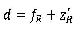
- For an embodiment of the multiperspective photography camera device of the present invention, the lens array is placed at a distance d from the at least one converging lens, wherein


- According to an embodiment, the multi perspective photography camera device of the present invention further comprises the above mentioned photographic objective housed within and attached to the hollow housing, and arranged behind the front opening so that light coming from the 3D scene passes first through the front opening, then through the photographic objective, then through the at least one converging lens and then through the lens array to impinge on the photosensitive pixel array sensor.
- For an implementation of the embodiment described in the immediately preceding paragraph, the multiperspective photography camera device of the present invention further comprises the above mentioned photosensitive pixel array sensor housed within and attached to the hollow housing, and arranged behind said lens array at a distance coincident with the focal distance fML of the lenses of the lens array, wherein the photosensitive pixel array sensor comprises several groups of photosensitive elements, each group comprising a plurality of photosensitive elements facing a respective lens of the lens array to sense light of a respective perspective image of the 3D scene. Hence, for the here described implementation, the multiperspective photography camera device constitutes a whole multiperspective photography camera, which preferably comprises other conventional optic devices included in photography cameras (such as a camera shutter), which have not been described in the present document not to obscure the description of the innovative components of the present invention.
- Preferably, each of said pluralities of photosensitive elements comprises at least 10,000 photosensitive elements, distributed for example in the form of a 100 × 100 two-dimensional square or hexagonal array. Specifically, for an embodiment where each lens of the lens array has an area of 1 mm2 and each photosensitive element, i.e. each pixel, of the photosensitive pixel array sensor has an area of 0.000010 mm2, then each plurality of photosensitive elements comprises about 100,000 photosensitive elements (pixels), exactly 102,400 if the plurality of photosensitive elements is in the form of a 320 × 320 two-dimensional square array.
- According to an embodiment of the multiperspective photography camera device of the present invention, the hollow casing further comprises a back opening for the exit of light coming from the lens array, and a back coupling arrangement for coupling the hollow casing to a camera body housing the photosensitive pixel array sensor, such that the back opening is optically communicated and aligned with an opening of said camera body and the lens array is distanced from the photosensitive pixel array sensor a distance coincident with the focal distance fML of the lenses of the lens array.
- For an implementation of the embodiment described in the immediately preceding paragraph, the multiperspective photography camera device of the present invention further comprises the above mentioned photographic objective housed within and attached to the hollow housing, and arranged behind the front opening so that light coming from the 3D scene passes first through the front opening, then through the photographic objective, then through the at least one converging lens and then through the lens array to impinge on the photosensitive pixel array sensor. For this implementation, the multiperspective photography camera device does not constitute a whole multiperspective photography camera, as it lacks the photosensitive pixel array sensor, but a module to be coupled to the above mentioned camera body that houses the photosensitive pixel array sensor, so that a photographic camera is built.
- For an alternative implementation of that embodiment, the multiperspective photography camera device of the present invention further comprises a front coupling arrangement for coupling the hollow casing to said photographic objective, such that the front opening of the hollow casing is optically communicated and aligned with the photographic objective and the requested value of

- For an embodiment, the multiperspective photography camera device of the present invention further comprises a front separation distance adjustment mechanism to adjust the separation distance between the photographic objective and the field diaphragm so that the requested value of

- According to an embodiment, the multiperspective photography camera device of the present invention further comprises a back separation distance adjustment mechanism to adjust the separation distance between the at least one converging lens and the lens array so that the requested value of

- For an embodiment, the lenses of the lens array are equidistantly separated a distance p between the centres of each two contiguous lenses.
- According to an embodiment, the lens array of the multiperspective photography camera device of the present invention is a J × J two-dimensional lens array, where preferably J ≤ 5.
- For an embodiment, the photosensitive pixel array sensor is formed by a two-dimensional pixel array of J × J groups of N × N photosensitive elements, where N = p/δp , where δp is the size of each photosensitive element, or pixel.
- The multi perspective photography camera device of the present invention further comprises, for an embodiment, processing means operatively connected to the photosensitive pixel array sensor to receive output signals and process output signals coming therefrom and being representative of the plurality of different perspectives of the 3D scene.
- For an alternative or complementary embodiment, the multiperspective photography camera device of the present invention further comprises communication means operatively connected to the photosensitive pixel array sensor to receive therefrom output signals being representative of the plurality of different perspectives of the 3D scene, and being configured to transmit the received output signals to remote processing means configured to process said output signals.
- For several embodiments of the multiperspective photography camera device of the present invention, the above mentioned processing means and/or remote processing means are configured to perform at least one of the following tasks, for static and dynamic scenes, by processing the received output signals: 3D image reconstruction of non-occluded and occluded objects, generation of depth maps, and ballistic photon signal strengthening.
- For a preferred embodiment, the multiperspective photography camera device of the present invention constitutes a passive device configured to operate under ambient light.
- The multiperspective photography camera device proposed by the present invention can be also used to capture 3D videos of the 3D scene, or a sequence of consecutive 3D photographs.
- The present invention allows the simultaneous capture of an array of elemental/perspective images (that is, of photographs from different perspectives) with high resolution of macroscopic 3D scenes.
- This set of elemental/perspective images allows, for both static and dynamic scenes, the calculation of stacks of high-resolution refocused images at different depths. In other words, it enables high-resolution refocusing a posteriori. This ability to refocus has the additional advantage that it can be carried out even in partially occluded scenes, since to reconstruct an occluded part it is enough that it is visible to at least one of the elemental/perspective images.
- From the elemental/perspective images, high-resolution depth maps of distant scenes can also be obtained in real time. This capability can have important applications in metrology.
- Another advantage comes from the ability of multiperspective systems to reinforce the signal of ballistic photons, compared to those that suffer from scattering. This enables the invention to obtain refocused images and depth maps in cloudy environments, such as the case where the 3D scene is located in a smoky or foggy environment.
- An additional application from the depth map is the computation of images for its display on auto-stereoscopic 3D monitors.
- Therefore, the use of the device of the present invention allows to capture the 3D structure of near and distant scenes, operating with ambient light and even in unfavorable conditions, such as an environment with fog, smoke, or other diffusive elements. This allows passive 3D metrology and variable environments.
- To sum up, some of the main advantages of the present invention over existing plenoptic camera devices, for all or some of its embodiments:
- Allows to directly capture, in a single shot, a set of elemental/perspective images of macroscopic 3D scenes.
- Elemental/perspective images have high resolution, since their resolution is not determined by the lens array but by the pixel density of the photosensitive pixel array sensor.
- Perspective images have a large depth of field since their hyperfocal distance is short.
- From the elemental/perspective images it is possible to calculate a stack of images refocused at different depths. Contrary to what happens with existing plenoptic cameras, all refocused images have the same angular resolution.
- All elemental/perspective images are associated with the same impulse response (Point Spread Function - PSF). This allows the simple and real-time application of computational deconvolution tools.
- Allows the calculation, with the usual computational tools, of high resolution depth maps. This enables high resolution passive metrology to be carried out remotely.
- Allows to perform all the above tasks with dynamic images if the sensor allows it.
- Some potential applications of the device of the present invention are listed below:
- Surveillance: The device allows the detection and tracking of moving elements in open or closed areas, even in conditions of an environment with fog or smoke.
- Macroscopic metrology: The device allows determining the position (x, y, z) of fixed or mobile elements in distant scenes.
- Security: The device allows to measure the structure (x, y, z) in scenes with little visibility, as is the case of scenes with smoke.
- Topography: The device allows the generation of depth maps to calculate distances and/or generate topographic maps.
- 3D scanner: The device allows 3D scans of, for example, people, furniture, etc.
- From the 3D depth map of nearby scenes, 3D images can be generated for projection on autostereoscopic monitors.
- In the following some preferred embodiments of the invention will be described with reference to some of the enclosed figures, particularly
Figures 4 to 8 . They are provided only for illustration purposes without however limiting the scope of the invention. In addition, some of the enclosed figures, particularlyfigures 1 to 3 , have been referred in the above background section to describe the state of the art. -
Figure 1 shows a ray map emitted by a 3D scene. In a plane perpendicular to the direction of propagation of the light beam, each light ray is characterized by two spatial coordinates (x, y) and two angular coordinates (θ, ϕ). -
Figure 2 shows a scheme of a conventional photography camera. Each pixel integrates all the light rays contained in a cone. These light rays are characterized by having the same spatial information, but different angular information. -
Figure 3 shows a scheme of a conventional plenoptic camera. Each microlens captures a micro-image. All the pixels in a micro-image carry the same spatial information, but different angular information. -
Figure 4 is a scheme of the multiperspective photography camera device of the present invention, for an embodiment corresponding to the implementation described in the previous section for which the multiperspective photography camera device constitutes a whole multiperspective photography camera. Each lens or the lens array provides a different perspective of the 3D scene. θmax is the angle of maximum parallax and


-
Figure 5 is a scheme showing the relative position between the image focus of a photographic objective and its exit pupil 2'. The exit pupil is the conjugate of the aperture diaphragm through L 2 . -
Figure 6 is a scheme of the multiperspective photography camera device of the present invention, for an embodiment corresponding to the implementation described in the previous section for which the multiperspective photography camera device constitutes a module to be coupled to a camera body that houses the photosensitive pixel array sensor, so that a photographic camera is built. This module can be called multiperspective photographic objective, as it includes the photographic objective. -
Figure 7 is a scheme of the multiperspective photography camera device of the present invention, for an embodiment corresponding to the implementation described in the previous section for which the multiperspective photography camera device constitutes a module to be intercoupled between an external photographic objective and a camera body that houses the photosensitive pixel array sensor, so that a photography camera is built. This module can be called perspective multiplexer accessory. -
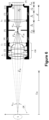
Figure 8 shows an image captured with a prototype of the multiperspective photography camera device of the present invention. -
Figure 9 shows the result of applying a refocusing algorithm to the images ofFigure 8 . The refocusing algorithm allows the posterior focus of different parts of the scene. In this case, the letters in the background (left image) or the letters in the foreground (right image). - In the present section some working embodiments of the present invention will be described with reference to
Figures 4 to 9 , referred below as first, second and third working embodiments, all of which show a multiperspective photography camera device comprising: - a
hollow casing 10a-10b, 11, 13 having a front opening for the entry of light coming from a 3D scene S to be photographed and placed at an object plane OP; and housed within and attached to thehollow casing 10a-10b, 11, 13: - a
lens array 8 configured and arranged to be placed between a photographic objective OB, having anaperture diaphragm 2, and a photosensitivepixel array sensor 9, to receive light coming from the 3D scene S and passing through the photographic objective OB and to transmit said received light to said photosensitivepixel array sensor 9; - a
field diaphragm 5, housed within and attached to thehollow casing 10a-10b, 11, 13, and configured and arranged to be placed at a plane where an image provided by the photographic objective OB is to be formed; and - at least one converging
lens 6 having a focal length fR, and that is placed between thefield diaphragm 5 and thelens array 8, at a distance equal to fR from thefield diaphragm 5. - For all those embodiments, the
lens array 8 is configured and arranged to be placed at a conjugate plane of saidaperture diaphragm 2 of the photographic objective OB, so that thelens array 8 is arranged to simultaneously receive and simultaneously transmit to the photosensitivepixel array sensor 9 light representative of a plurality of different perspectives of the 3D scene S, one perspective per array lens. - Specifically, for the first working embodiment illustrated by
Figure 4 , the multiperspective photography camera device is a whole photography camera. Two essential conjugation relationships can be seen in the scheme shown in that figure, namely: (a) The object plane OP is conjugated with thefield diaphragm 5, and this with the photosensitivepixel array sensor 9; (b) Theaperture diaphragm 2 of the photographic objective OB is conjugated with thelens array 8. If one looks at the path of the central light rays, one can see that each lens of thelens array 8 provides a different image of the 3D object S to the photosensitivepixel array sensor 9. Each lens "sees" the object S from a different perspective. For this reason, these images are called perspective images, or also elemental images. The angle θmax formed by the central light rays corresponding to the outermost lenses of thelens array 8 defines the maximum difference in perspective angle, and is called the angle of maximum parallax. In short, the multi perspective camera provides directly, and with a single shot, a set of images with different perspective of the 3D scene. - As seen in
Figure 4 , the multiperspective photography camera there illustrated comprises a hollow casing which, for the illustrated embodiment, is formed by a fronthollow casing portion 10a and a backhollow casing portion 10b, coupled to each other, but for non-illustrated embodiments is formed by a single-piece hollow casing. - The photography camera of
Figure 4 comprises the following components housed within and attached to the fronthollow casing portion 10a: - OB: Photographic objective of focal length f ob (the focal length of a lens or lens coupling arrangement is often called the effective focal length (EFL)), and that, for the illustrated embodiment, is composed of:
- 1: Converging lens (or lens coupling arrangement) L 1 of focal length f 1
- 2: Aperture diaphragm of diameter φA ;
- 3: Converging lens (or lens coupling arrangement) L 2 of focal length f 2.
- A perspective multiplexer module composed of:
5: Field diaphragm of diameter φF that is located on the plane in which the image provided by the photographic objective OB is formed. Therefore, the distance from the photographic objective OB to thefield diaphragm 5 is modifiable depending on the distance to the focused object S. In case where the camera focuses on an object at infinity, thefield diaphragm 5 is placed at the image focus of the photographic objective OB. When focusing on closer objects, thefield diaphragm 5 is positioned at a distance

- The mission of the
field diaphragm 5 is to avoid overlapping between elemental images. Therefore, its diameter must satisfy the following equation:
- 4: Front separation distance adjustment mechanism, formed for example by a thread or telescopic system, to adjust the separation distance between the converging
lens 3 of photographic objective OB and thefield diaphragm 5 so that the requested value of
- 6: Converging lens LR (or lens coupling arrangement) of focal length fR, which is located at a distance fR from the
field diaphragm 5. - 8: Lens array with focal length fML and equidistance p between lenses. The
lens array 8 is located in a plane conjugated to theaperture diaphragm 2 of the photographic objective OB. This conjugation occurs under the joint action of the second converging lens L 2 of the photographic objective OB and the converging lens LR. Expressing this property in mathematical terms, thelens array 8 is located at a distance


aperture diaphragm 2 through L 2, to
Figure 5 . - 7: Back separation distance adjustment mechanism, formed for example by a thread or telescopic system, that allows modifying the separation distance between the converging
lens 6 and thelens array 8 so that the requested value of
- For the embodiment of
Figure 4 , the multi perspective photography camera further comprises the following components, but not housed within fronthollow casing 10a: - Multiperspective camera body, composed of:
10b: The above mentioned back hollow casing to which the fronthollow casing 10a is coupled (mechanically and optically), and within which the following component is housed and attached to:
9: A pixelated photosensitive recording medium (such as a CCD or CMOS sensor), or photosensitive pixel array sensor, with pixel size δp located at a distance fML from the lenses of thelens array 8. This medium records the elemental images, and comprises communication means configured to transmit the set of elemental images (or output signals representative thereof) to external remote image processing means and/or are operatively connected to local processing means to process those elemental images (or output signals representative thereof). - The number of elemental images J × J depends on the value of p. The higher the value of J, the greater the number of perspectives captured and therefore the higher the angular resolution. However, and since all the elemental images are captured simultaneously by the
same sensor 9, a high value of J results in elemental images made up of few pixels. To obtain a good compromise between spatial and angular resolution, it is recommended to implement the device so that J ≤ 5. - The number of pixels in each elemental image is N × N, where N = p/δp.
- The f-number associated with each elemental image,


- It is well known that a photographic camera focused at the hyperfocal distance, aH, provides sharp images for objects located between aH /2 to infinity. For each of the elemental images the hyperfocal distance is equal to

- Another important property is the parallax with which the objects photographed with the device of the present invention are observed. This parameter is quantified by the maximum parallax angle θmax (see
Figure 4 ). θmax is the angle subtended by theaperture diaphragm 2 from the centre of the object S. Mathematically, θmax is calculated with the following expressions:

- A last parameter of interest is the field of view (FOV) photographed by each elemental image, which can be calculated as:


- Considering, for example, the following practical case: (a) Photographic objective OB: fob = 35 mm, f # = 2.8; (b) Lens LR : fR = 25 mm. (c) Lenses of the lens array 8: p = 1.30 mm, fML = 7.80 mm; (d) Photosensitive pixel array sensor 9: δp = 2.2 µm, the following results are obtained for the particular case of an object located 2.0 meters from the photographic objective OB:
- i) Position of the field diaphragm 5:

- ii) Position of the lens array 8: d = 39.7 mm.
- iii) Number of elemental images: J = 5.64.
- iv) Diameter of the field diaphragm 5: φF = 4.17 mm.
- v) Number of pixels per elemental image: 590 × 590.
- vi) Angle of maximum parallax: 0.3°.
- vii) Field of view: 240 mm.
- viii) Total magnification of the photography camera: MT = 0.005.
- vii) Hyperfocal distance: 17.0 m.
- The proposed multiperspective photography camera device works with distant objects (generally located several metres away), captures large fields (depending on the distances they can be up to metres), captures very small parallaxes (generally a few tenths degree) and provides elemental images with a very small scale (in the above particular case 200 times smaller than the object).
- A second working embodiment of the multiperspective photography camera device of the present invention is shown in
Figure 6 shows a further embodiment, particularly that for which the device implements a module called herein multiperspective photographic objective, which can be attached to a photography camera body that houses the photosensitivepixel array sensor 9. The device ofFigure 6 includes the following components: - 11: Casing in which the following components are housed and attached:
- 1: Converging lens (or lens coupling arrangement) L 1 of focal length f 1.
- 2: Aperture diaphragm of diameter φA ;
- 3: Converging lens (or lens coupling arrangement) L 2 of focal length f 2.
- 5: Field diaphragm of diameter φF .
- 6: Converging lens LR (or lens coupling arrangement) of focal length fR, which is located at a distance fR from the
field diaphragm 5. - 8: Lens array with focal length fML and equidistance p between lenses, and located in a plane conjugated to the
aperture diaphragm 2 of the photographic objective OB.
- 4: Front separation distance adjustment mechanism, formed for example by a thread or telescopic system (in this case defined in a perimeter wall of casing 11), that allows modifying the separation distance between the converging
lens 3 of photographic objective OB and thefield diaphragm 5 so that the requested value of
- 7: Back separation distance adjustment mechanism, formed for example by a thread or telescopic system (in this case defined in a perimeter wall of casing 11), that allows modifying the separation distance between the converging
lens 6 and thelens array 8 so that the requested value of
- 12: A back coupling arrangement, such as a male thread (in this case defined at a back end of
casing 11, surrounding a back opening thereof), for coupling the multiperspective photographic objective to a camera body housing the photosensitivepixel array sensor 9. - A third working embodiment of the multiperspective photography camera device of the present invention is shown in
Figure 7 shows a further embodiment, particularly that for which the device implements a module called herein perspective multiplexer accessory, which is configured and arranged to be intercoupled between an external photographic objective OB and a camera body that houses the photosensitivepixel array sensor 9. The device ofFigure 7 includes the following components: - 13: Casing in which the following components are housed and attached:
- 5: Field diaphragm of diameter φF .
- 6: Converging lens LR (or lens coupling arrangement) of focal length fR , which is located at a distance fR from the
field diaphragm 5. - 8: Lens array with focal length fML and equidistance p between lenses, and located in a plane conjugated to the
aperture diaphragm 2 of the photographic objective OB.
- 7: Back separation distance adjustment mechanism, formed for example by a thread or telescopic system (in this case defined in a perimeter wall of casing 13), that allows modifying the separation distance between the converging
lens 6 and thelens array 8 so that the requested value of
- 12: A back coupling arrangement, such as a male thread (in this case defined at a back end of
casing 13, surrounding a back opening thereof), for coupling the perspective multiplexer accessory to a camera body housing the photosensitivepixel array sensor 8. - 14: A front coupling arrangement, such as a female thread (in this case defined at a front end of
casing 13, specifically in the contour of a front opening thereof), for coupling the perspective multiplexer accessory to a photographic objective OB. - All what has been explained above regarding the first working embodiment, with respect to the operation of the device and to the locations at which the different components of the device must be placed, is also valid for both the second and third working embodiments of the multiperspective photographic camera device of the present invention.
- Finally, a prototype of the multiperspective photographic camera device of the present invention has been built by the present inventors, with which the image of
Figure 8 has been captured. The image consists of ten elemental images in a hexagonal arrangement. InFigure 9 the result of applying a refocusing algorithm by the local and/or remote processing means is shown, particularly to focus a background part of the scene, (left image) and a foreground part of the scene (right view). -
- [1] E. H. Adelson and J. R. Bergen, "The plenoptic function and the elements of early vision," in Computational Models of Visual Processing, L. M. and J. Movshon, eds. (MIT Press, Camdridge. MA, 1991), pp. 3-20.
- [2] E. H. Adelson and J. Y. A. Wang, "Single lens stereo with a plenoptic camera," IEEE Trans. Pattern Anal. Mach. Intell. pp. 99-106 (1992).
- [3] R. Ng, M. Levoy, M. Brédif, G. Duval, M. Horowitz, and P. Hanrahan, "Light field photography with a hand-held plenoptic camera," Tech. rep., Standford University (2005).
- [4]
R. Gregory et al., "Conversion of at least one non-stereocamera into a stereo camera" US 2015/0103146 A1 - [5]
R. Ng et al., "Light field data acquisition", US8,724,014 B2 . - [6]
T. Georgiev, "Plenoptic camera", US 2010/0020187 A1 . - [7]
C. Liang et al., "Camera using programable aperture", US 2008/0124070 A1 . - [8]
Z. Zalevsky et al., "Three-dimensional sensing using speckle patterns" US 8,390,821 B2 - [9] R. Lange, P. Seitz, A. Biber and R. Schwarte, "Time-of-flight range imaging with a custom solid-state image sensor," Laser Metrology Inspection, vol. 3823, pp. 180-191, 1999.
Claims (15)
- A multiperspective photography camera device, for capturing perspective images of a macroscopic 3D scene, comprising:- a hollow casing (10a-10b, 11, 13) having a front opening for the entry of light coming from a macroscopic 3D scene (S) to be photographed and placed at an object plane (OP); and housed within and attached to said hollow casing (10a-10b, 11, 13):- a lens array (8) configured and arranged to be placed between a photographic objective (OB), having an aperture diaphragm (2), and a photosensitive pixel array sensor (9), to receive light coming from said macroscopic 3D scene (S) and passing through the photographic objective (OB) and to transmit said received light to said photosensitive pixel array sensor (9);characterized in that the multi perspective photography camera device further comprises, housed within and attached to said hollow casing (10a-10b, 11, 13):- a field diaphragm (5) configured and arranged to be placed at a plane where an image provided by said photographic objective (OB) is to be formed; and- at least one converging lens (6) having a focal length fR, and that is placed between said field diaphragm (5) and said lens array (8), at a distance equal to fR from the field diaphragm (5);and in that the lens array (8) is configured and arranged to be placed at a conjugate plane of said aperture diaphragm (2) of the photographic objective (OB), so that the lens array (8) is arranged to simultaneously receive and simultaneously transmit to the photosensitive pixel array sensor (9) light representative of a plurality of different perspectives of the macroscopic 3D scene (S), one perspective per array lens.
- The multiperspective photography camera device of any of the previous claims, wherein the lens array (8) is placed at a distance d from the at least one converging lens (6), wherein


- The multiperspective photography camera device of claim 1 or 2, further comprising said photographic objective (OB) housed within and attached to the hollow housing (10a-10b, 11), and arranged behind said front opening so that light coming from the macroscopic 3D scene (S) passes first through the front opening, then through the photographic objective (OB), then through the at least one converging lens (6) and then through the lens array (8) to impinge on the photosensitive pixel array sensor (9).
- The multiperspective photography camera device of claim 3, further comprising said photosensitive pixel array sensor (9) housed within and attached to the hollow housing (10a-10b), and arranged behind said lens array (8) at a distance coincident with the focal distance fML of the lenses of the lens array (8), wherein the photosensitive pixel array sensor (9) comprises several groups of photosensitive elements, each group comprising a plurality of photosensitive elements facing a respective lens of the lens array (8) to sense light of a respective perspective image of the macroscopic 3D scene (S).
- The multiperspective photography camera device of claim 4, wherein each of said pluralities of photosensitive elements comprises at least 10,000 photosensitive elements.
- The multiperspective photography camera device of claim 1, 2 or 3, wherein said hollow casing (11, 13) further comprises a back opening for the exit of light coming from the lens array (8), and a back coupling arrangement (12) for coupling the hollow casing (11, 13) to a camera body housing said photosensitive pixel array sensor (9), such that said back opening is optically communicated and aligned with an opening of said camera body and the lens array (8) is distanced from the photosensitive pixel array sensor (9) a distance coincident with the focal distance fML of the lenses of the lens array (8).
- The multiperspective photography camera device of claim 6 when depending on claim 2, further comprising a front coupling arrangement (14) for coupling the hollow casing (11) to said photographic objective (OB), such that said front opening is optically communicated and aligned with the same and the requested value of

- The multiperspective photography camera device of claim 3 when depending on claim 2, or of claims 4 or 6 when depending on claim 2 through claim 3, further comprising a front separation distance adjustment mechanism (4) to adjust the separation distance between the photographic objective (OB) and the field diaphragm (5) so that the requested value of

- The multiperspective photography camera device of any of claims 3 to 8, when depending on claim 2, further comprising a back separation distance adjustment mechanism (7) to adjust the separation distance between the at least one converging lens (6) and the lens array (8) so that the requested value of

- The multiperspective photography camera device of any of the previous claims, wherein the lenses of the lens array (8) are equidistantly separated a distance p between the centres of each two contiguous lenses.
- The multiperspective photography camera device of claim 10 when depending on claim 4 or 5, wherein said lens array (8) is a J × J two-dimensional lens array (8), where preferably J ≤ 5, and wherein the photosensitive pixel array sensor (9) is formed by a two-dimensional pixel array of J × J groups of N × N photosensitive elements, where N = p/δp , where δp is the size of each photosensitive element, or pixel.
- The multi perspective photography camera device of claim 6 or 11, further comprising processing means operatively connected to the photosensitive pixel array sensor (9) to receive output signals and process output signals coming therefrom and being representative of the plurality of different perspectives of the macroscopic 3D scene (S).
- The multiperspective photography camera device of claim 6 or 11, further comprising communication means operatively connected to the photosensitive pixel array sensor (9) to receive therefrom output signals being representative of the plurality of different perspectives of the macroscopic 3D scene (S), and being configured to transmit the received output signals to remote processing means configured to process said output signals.
- The multiperspective photography camera device of claim 12, wherein said processing means are configured to perform at least one of the following tasks, for static and dynamic scenes (S), by processing the received output signals: 3D image reconstruction of non-occluded and occluded objects, generation of depth maps, and ballistic photon signal strengthening.
- The multiperspective photography camera device of any of the previous claims, constituting a passive device configured to operate under ambient light.
Applications Claiming Priority (2)
| Application Number | Priority Date | Filing Date | Title |
|---|---|---|---|
| EP20382942.9A EP3993385A1 (en) | 2020-10-29 | 2020-10-29 | A multiperspective photography camera device |
| PCT/EP2021/079900 WO2022090352A1 (en) | 2020-10-29 | 2021-10-27 | A multiperspective photography camera device |
Publications (3)
| Publication Number | Publication Date |
|---|---|
| EP4238303A1 EP4238303A1 (en) | 2023-09-06 |
| EP4238303B1 true EP4238303B1 (en) | 2024-07-24 |
| EP4238303C0 EP4238303C0 (en) | 2024-07-24 |
Family
ID=73642778
Family Applications (2)
| Application Number | Title | Priority Date | Filing Date |
|---|---|---|---|
| EP20382942.9A Withdrawn EP3993385A1 (en) | 2020-10-29 | 2020-10-29 | A multiperspective photography camera device |
| EP21801885.1A Active EP4238303B1 (en) | 2020-10-29 | 2021-10-27 | A multiperspective photography camera device |
Family Applications Before (1)
| Application Number | Title | Priority Date | Filing Date |
|---|---|---|---|
| EP20382942.9A Withdrawn EP3993385A1 (en) | 2020-10-29 | 2020-10-29 | A multiperspective photography camera device |
Country Status (4)
| Country | Link |
|---|---|
| US (1) | US12253689B2 (en) |
| EP (2) | EP3993385A1 (en) |
| ES (1) | ES2993432T3 (en) |
| WO (1) | WO2022090352A1 (en) |
Families Citing this family (2)
| Publication number | Priority date | Publication date | Assignee | Title |
|---|---|---|---|---|
| CN112465715B (en) * | 2020-11-25 | 2023-08-08 | 清华大学深圳国际研究生院 | An Image Descattering Method Based on Iterative Optimization of Atmospheric Transport Matrix |
| CN118433508B (en) * | 2024-06-25 | 2024-11-01 | 杭州海康威视数字技术股份有限公司 | Camera device |
Family Cites Families (11)
| Publication number | Priority date | Publication date | Assignee | Title |
|---|---|---|---|---|
| US7463280B2 (en) * | 2003-06-03 | 2008-12-09 | Steuart Iii Leonard P | Digital 3D/360 degree camera system |
| US8390821B2 (en) | 2005-10-11 | 2013-03-05 | Primesense Ltd. | Three-dimensional sensing using speckle patterns |
| US7620309B2 (en) | 2006-04-04 | 2009-11-17 | Adobe Systems, Incorporated | Plenoptic camera |
| EP2050067A1 (en) * | 2006-08-03 | 2009-04-22 | Alterface S.A. | Method and device for identifying and extracting images of multiple users, and for recognizing user gestures |
| TW200823595A (en) | 2006-11-28 | 2008-06-01 | Univ Nat Taiwan | Image capture device using programmable aperture |
| WO2010077625A1 (en) | 2008-12-08 | 2010-07-08 | Refocus Imaging, Inc. | Light field data acquisition devices, and methods of using and manufacturing same |
| US9113043B1 (en) * | 2011-10-24 | 2015-08-18 | Disney Enterprises, Inc. | Multi-perspective stereoscopy from light fields |
| US20150103146A1 (en) | 2013-10-16 | 2015-04-16 | Qualcomm Incorporated | Conversion of at least one non-stereo camera into a stereo camera |
| US11604343B2 (en) * | 2018-08-08 | 2023-03-14 | Universitat De Valencia | Plenoptic ocular device |
| CN111487759B (en) * | 2020-06-04 | 2025-05-02 | 深圳开立生物医疗科技股份有限公司 | A multi-aperture imaging system, an endoscope, and an endoscope system |
| KR20220121533A (en) * | 2021-02-25 | 2022-09-01 | 삼성전자주식회사 | Image restoration method and image restoration apparatus for restoring images acquired through an array camera |
-
2020
- 2020-10-29 EP EP20382942.9A patent/EP3993385A1/en not_active Withdrawn
-
2021
- 2021-10-27 US US18/251,154 patent/US12253689B2/en active Active
- 2021-10-27 WO PCT/EP2021/079900 patent/WO2022090352A1/en not_active Ceased
- 2021-10-27 EP EP21801885.1A patent/EP4238303B1/en active Active
- 2021-10-27 ES ES21801885T patent/ES2993432T3/en active Active
Also Published As
| Publication number | Publication date |
|---|---|
| EP3993385A1 (en) | 2022-05-04 |
| EP4238303A1 (en) | 2023-09-06 |
| US20230421872A1 (en) | 2023-12-28 |
| WO2022090352A1 (en) | 2022-05-05 |
| US12253689B2 (en) | 2025-03-18 |
| EP4238303C0 (en) | 2024-07-24 |
| ES2993432T3 (en) | 2024-12-30 |
Similar Documents
| Publication | Publication Date | Title |
|---|---|---|
| JP7043085B2 (en) | Devices and methods for acquiring distance information from a viewpoint | |
| Zhou et al. | Computational cameras: convergence of optics and processing | |
| CN104463949B (en) | A kind of quick three-dimensional reconstructing method and its system based on light field numeral refocusing | |
| US10715711B2 (en) | Adaptive three-dimensional imaging system and methods and uses thereof | |
| EP2008445B1 (en) | Improved plenoptic camera | |
| DE102006031114B4 (en) | 3D combination meter from digital camera and laser scanner | |
| CN108924408B (en) | Depth imaging method and system | |
| JP4673202B2 (en) | Image input device | |
| CN103323113A (en) | Multispectral imager based on light fieldd imaging technique | |
| US12549872B2 (en) | Image sensors and sensing methods to obtain time-of-flight and phase detection information | |
| US12253689B2 (en) | Multiperspective photography camera device | |
| CN107454377A (en) | A kind of algorithm and system that three-dimensional imaging is carried out using camera | |
| CN108881717B (en) | Depth imaging method and system | |
| CN108924407B (en) | Depth imaging method and system | |
| CN117395485A (en) | Integrated polarized light field depth perception imaging device and method adopting same | |
| US11523097B2 (en) | Process and apparatus for the capture of plenoptic images between arbitrary planes | |
| TWI687661B (en) | Method and device for determining the complex amplitude of the electromagnetic field associated to a scene | |
| Fachada et al. | Pattern-free plenoptic 2.0 camera calibration | |
| EP3758574B1 (en) | Imaging system and method | |
| JP2002191060A (en) | Three-dimensional imaging unit | |
| Xue et al. | A compact visible bionic compound eyes system based on micro-surface fiber faceplate | |
| CN111277811B (en) | Three-dimensional space camera and photographing method thereof | |
| TORTOSA et al. | International Bureau | |
| KR20230024231A (en) | System and method for extracting information on the spatial distribution of wavefronts | |
| CN119383327B (en) | A distributed defocus stereo camera |
Legal Events
| Date | Code | Title | Description |
|---|---|---|---|
| STAA | Information on the status of an ep patent application or granted ep patent |
Free format text: STATUS: UNKNOWN |
|
| STAA | Information on the status of an ep patent application or granted ep patent |
Free format text: STATUS: THE INTERNATIONAL PUBLICATION HAS BEEN MADE |
|
| PUAI | Public reference made under article 153(3) epc to a published international application that has entered the european phase |
Free format text: ORIGINAL CODE: 0009012 |
|
| STAA | Information on the status of an ep patent application or granted ep patent |
Free format text: STATUS: REQUEST FOR EXAMINATION WAS MADE |
|
| 17P | Request for examination filed |
Effective date: 20230526 |
|
| AK | Designated contracting states |
Kind code of ref document: A1 Designated state(s): AL AT BE BG CH CY CZ DE DK EE ES FI FR GB GR HR HU IE IS IT LI LT LU LV MC MK MT NL NO PL PT RO RS SE SI SK SM TR |
|
| DAV | Request for validation of the european patent (deleted) | ||
| DAX | Request for extension of the european patent (deleted) | ||
| REG | Reference to a national code |
Ref country code: DE Ref legal event code: R079 Free format text: PREVIOUS MAIN CLASS: H04N0005225000 Ipc: G02B0030000000 Ref country code: DE Ref legal event code: R079 Ref document number: 602021016250 Country of ref document: DE Free format text: PREVIOUS MAIN CLASS: H04N0005225000 Ipc: G02B0030000000 |
|
| GRAP | Despatch of communication of intention to grant a patent |
Free format text: ORIGINAL CODE: EPIDOSNIGR1 |
|
| STAA | Information on the status of an ep patent application or granted ep patent |
Free format text: STATUS: GRANT OF PATENT IS INTENDED |
|
| GRAS | Grant fee paid |
Free format text: ORIGINAL CODE: EPIDOSNIGR3 |
|
| RIC1 | Information provided on ipc code assigned before grant |
Ipc: H04N 23/957 20230101ALI20240513BHEP Ipc: H04N 23/55 20230101ALI20240513BHEP Ipc: H04N 23/51 20230101ALI20240513BHEP Ipc: G02B 27/00 20060101ALI20240513BHEP Ipc: G02B 30/00 20200101AFI20240513BHEP |
|
| GRAA | (expected) grant |
Free format text: ORIGINAL CODE: 0009210 |
|
| STAA | Information on the status of an ep patent application or granted ep patent |
Free format text: STATUS: THE PATENT HAS BEEN GRANTED |
|
| INTG | Intention to grant announced |
Effective date: 20240603 |
|
| AK | Designated contracting states |
Kind code of ref document: B1 Designated state(s): AL AT BE BG CH CY CZ DE DK EE ES FI FR GB GR HR HU IE IS IT LI LT LU LV MC MK MT NL NO PL PT RO RS SE SI SK SM TR |
|
| REG | Reference to a national code |
Ref country code: GB Ref legal event code: FG4D |
|
| REG | Reference to a national code |
Ref country code: CH Ref legal event code: EP |
|
| REG | Reference to a national code |
Ref country code: DE Ref legal event code: R096 Ref document number: 602021016250 Country of ref document: DE |
|
| REG | Reference to a national code |
Ref country code: IE Ref legal event code: FG4D |
|
| U01 | Request for unitary effect filed |
Effective date: 20240812 |
|
| U07 | Unitary effect registered |
Designated state(s): AT BE BG DE DK EE FI FR IT LT LU LV MT NL PT SE SI Effective date: 20240816 |
|
| U20 | Renewal fee for the european patent with unitary effect paid |
Year of fee payment: 4 Effective date: 20241008 |
|
| REG | Reference to a national code |
Ref country code: ES Ref legal event code: FG2A Ref document number: 2993432 Country of ref document: ES Kind code of ref document: T3 Effective date: 20241230 |
|
| PG25 | Lapsed in a contracting state [announced via postgrant information from national office to epo] |
Ref country code: NO Free format text: LAPSE BECAUSE OF FAILURE TO SUBMIT A TRANSLATION OF THE DESCRIPTION OR TO PAY THE FEE WITHIN THE PRESCRIBED TIME-LIMIT Effective date: 20241024 |
|
| PG25 | Lapsed in a contracting state [announced via postgrant information from national office to epo] |
Ref country code: GR Free format text: LAPSE BECAUSE OF FAILURE TO SUBMIT A TRANSLATION OF THE DESCRIPTION OR TO PAY THE FEE WITHIN THE PRESCRIBED TIME-LIMIT Effective date: 20241025 Ref country code: PL Free format text: LAPSE BECAUSE OF FAILURE TO SUBMIT A TRANSLATION OF THE DESCRIPTION OR TO PAY THE FEE WITHIN THE PRESCRIBED TIME-LIMIT Effective date: 20240724 |
|
| PG25 | Lapsed in a contracting state [announced via postgrant information from national office to epo] |
Ref country code: IS Free format text: LAPSE BECAUSE OF FAILURE TO SUBMIT A TRANSLATION OF THE DESCRIPTION OR TO PAY THE FEE WITHIN THE PRESCRIBED TIME-LIMIT Effective date: 20241124 |
|
| PG25 | Lapsed in a contracting state [announced via postgrant information from national office to epo] |
Ref country code: HR Free format text: LAPSE BECAUSE OF FAILURE TO SUBMIT A TRANSLATION OF THE DESCRIPTION OR TO PAY THE FEE WITHIN THE PRESCRIBED TIME-LIMIT Effective date: 20240724 |
|
| PG25 | Lapsed in a contracting state [announced via postgrant information from national office to epo] |
Ref country code: RS Free format text: LAPSE BECAUSE OF FAILURE TO SUBMIT A TRANSLATION OF THE DESCRIPTION OR TO PAY THE FEE WITHIN THE PRESCRIBED TIME-LIMIT Effective date: 20241024 |
|
| PG25 | Lapsed in a contracting state [announced via postgrant information from national office to epo] |
Ref country code: RS Free format text: LAPSE BECAUSE OF FAILURE TO SUBMIT A TRANSLATION OF THE DESCRIPTION OR TO PAY THE FEE WITHIN THE PRESCRIBED TIME-LIMIT Effective date: 20241024 Ref country code: PL Free format text: LAPSE BECAUSE OF FAILURE TO SUBMIT A TRANSLATION OF THE DESCRIPTION OR TO PAY THE FEE WITHIN THE PRESCRIBED TIME-LIMIT Effective date: 20240724 Ref country code: NO Free format text: LAPSE BECAUSE OF FAILURE TO SUBMIT A TRANSLATION OF THE DESCRIPTION OR TO PAY THE FEE WITHIN THE PRESCRIBED TIME-LIMIT Effective date: 20241024 Ref country code: IS Free format text: LAPSE BECAUSE OF FAILURE TO SUBMIT A TRANSLATION OF THE DESCRIPTION OR TO PAY THE FEE WITHIN THE PRESCRIBED TIME-LIMIT Effective date: 20241124 Ref country code: HR Free format text: LAPSE BECAUSE OF FAILURE TO SUBMIT A TRANSLATION OF THE DESCRIPTION OR TO PAY THE FEE WITHIN THE PRESCRIBED TIME-LIMIT Effective date: 20240724 Ref country code: GR Free format text: LAPSE BECAUSE OF FAILURE TO SUBMIT A TRANSLATION OF THE DESCRIPTION OR TO PAY THE FEE WITHIN THE PRESCRIBED TIME-LIMIT Effective date: 20241025 |
|
| PG25 | Lapsed in a contracting state [announced via postgrant information from national office to epo] |
Ref country code: RO Free format text: LAPSE BECAUSE OF FAILURE TO SUBMIT A TRANSLATION OF THE DESCRIPTION OR TO PAY THE FEE WITHIN THE PRESCRIBED TIME-LIMIT Effective date: 20240724 Ref country code: SM Free format text: LAPSE BECAUSE OF FAILURE TO SUBMIT A TRANSLATION OF THE DESCRIPTION OR TO PAY THE FEE WITHIN THE PRESCRIBED TIME-LIMIT Effective date: 20240724 |
|
| PGFP | Annual fee paid to national office [announced via postgrant information from national office to epo] |
Ref country code: ES Payment date: 20241231 Year of fee payment: 4 |
|
| PG25 | Lapsed in a contracting state [announced via postgrant information from national office to epo] |
Ref country code: CZ Free format text: LAPSE BECAUSE OF FAILURE TO SUBMIT A TRANSLATION OF THE DESCRIPTION OR TO PAY THE FEE WITHIN THE PRESCRIBED TIME-LIMIT Effective date: 20240724 |
|
| PG25 | Lapsed in a contracting state [announced via postgrant information from national office to epo] |
Ref country code: SK Free format text: LAPSE BECAUSE OF FAILURE TO SUBMIT A TRANSLATION OF THE DESCRIPTION OR TO PAY THE FEE WITHIN THE PRESCRIBED TIME-LIMIT Effective date: 20240724 |
|
| PLBE | No opposition filed within time limit |
Free format text: ORIGINAL CODE: 0009261 |
|
| STAA | Information on the status of an ep patent application or granted ep patent |
Free format text: STATUS: NO OPPOSITION FILED WITHIN TIME LIMIT |
|
| REG | Reference to a national code |
Ref country code: CH Ref legal event code: PL |
|
| 26N | No opposition filed |
Effective date: 20250425 |
|
| PG25 | Lapsed in a contracting state [announced via postgrant information from national office to epo] |
Ref country code: MC Free format text: LAPSE BECAUSE OF FAILURE TO SUBMIT A TRANSLATION OF THE DESCRIPTION OR TO PAY THE FEE WITHIN THE PRESCRIBED TIME-LIMIT Effective date: 20240724 |
|
| PG25 | Lapsed in a contracting state [announced via postgrant information from national office to epo] |
Ref country code: CH Free format text: LAPSE BECAUSE OF NON-PAYMENT OF DUE FEES Effective date: 20241031 |
|
| PG25 | Lapsed in a contracting state [announced via postgrant information from national office to epo] |
Ref country code: IE Free format text: LAPSE BECAUSE OF NON-PAYMENT OF DUE FEES Effective date: 20241027 |
|
| PG25 | Lapsed in a contracting state [announced via postgrant information from national office to epo] |
Ref country code: CY Free format text: LAPSE BECAUSE OF FAILURE TO SUBMIT A TRANSLATION OF THE DESCRIPTION OR TO PAY THE FEE WITHIN THE PRESCRIBED TIME-LIMIT; INVALID AB INITIO Effective date: 20211027 |
|
| PG25 | Lapsed in a contracting state [announced via postgrant information from national office to epo] |
Ref country code: HU Free format text: LAPSE BECAUSE OF FAILURE TO SUBMIT A TRANSLATION OF THE DESCRIPTION OR TO PAY THE FEE WITHIN THE PRESCRIBED TIME-LIMIT; INVALID AB INITIO Effective date: 20211027 |