EP4237824B1 - Device for determining the position of trapped objects in optical tweezers - Google Patents
Device for determining the position of trapped objects in optical tweezers Download PDFInfo
- Publication number
- EP4237824B1 EP4237824B1 EP20861969.2A EP20861969A EP4237824B1 EP 4237824 B1 EP4237824 B1 EP 4237824B1 EP 20861969 A EP20861969 A EP 20861969A EP 4237824 B1 EP4237824 B1 EP 4237824B1
- Authority
- EP
- European Patent Office
- Prior art keywords
- objects
- trapped
- laser beam
- laser
- force
- Prior art date
- Legal status (The legal status is an assumption and is not a legal conclusion. Google has not performed a legal analysis and makes no representation as to the accuracy of the status listed.)
- Active
Links
Images




Classifications
-
- G—PHYSICS
- G01—MEASURING; TESTING
- G01N—INVESTIGATING OR ANALYSING MATERIALS BY DETERMINING THEIR CHEMICAL OR PHYSICAL PROPERTIES
- G01N15/00—Investigating characteristics of particles; Investigating permeability, pore-volume or surface-area of porous materials
- G01N15/10—Investigating individual particles
-
- G—PHYSICS
- G01—MEASURING; TESTING
- G01N—INVESTIGATING OR ANALYSING MATERIALS BY DETERMINING THEIR CHEMICAL OR PHYSICAL PROPERTIES
- G01N15/00—Investigating characteristics of particles; Investigating permeability, pore-volume or surface-area of porous materials
- G01N15/10—Investigating individual particles
- G01N15/14—Optical investigation techniques, e.g. flow cytometry
- G01N15/1434—Optical arrangements
-
- G—PHYSICS
- G02—OPTICS
- G02B—OPTICAL ELEMENTS, SYSTEMS OR APPARATUS
- G02B21/00—Microscopes
- G02B21/0004—Microscopes specially adapted for specific applications
- G02B21/0088—Inverse microscopes
-
- G—PHYSICS
- G02—OPTICS
- G02B—OPTICAL ELEMENTS, SYSTEMS OR APPARATUS
- G02B21/00—Microscopes
- G02B21/32—Micromanipulators structurally combined with microscopes
-
- G—PHYSICS
- G02—OPTICS
- G02B—OPTICAL ELEMENTS, SYSTEMS OR APPARATUS
- G02B26/00—Optical devices or arrangements for the control of light using movable or deformable optical elements
- G02B26/08—Optical devices or arrangements for the control of light using movable or deformable optical elements for controlling the direction of light
- G02B26/10—Scanning systems
- G02B26/105—Scanning systems with one or more pivoting mirrors or galvano-mirrors
-
- G—PHYSICS
- G01—MEASURING; TESTING
- G01N—INVESTIGATING OR ANALYSING MATERIALS BY DETERMINING THEIR CHEMICAL OR PHYSICAL PROPERTIES
- G01N15/00—Investigating characteristics of particles; Investigating permeability, pore-volume or surface-area of porous materials
- G01N15/10—Investigating individual particles
- G01N15/14—Optical investigation techniques, e.g. flow cytometry
- G01N15/1404—Handling flow, e.g. hydrodynamic focusing
- G01N2015/1415—Control of particle position
-
- G—PHYSICS
- G02—OPTICS
- G02B—OPTICAL ELEMENTS, SYSTEMS OR APPARATUS
- G02B21/00—Microscopes
- G02B21/36—Microscopes arranged for photographic purposes or projection purposes or digital imaging or video purposes including associated control and data processing arrangements
-
- G—PHYSICS
- G02—OPTICS
- G02B—OPTICAL ELEMENTS, SYSTEMS OR APPARATUS
- G02B26/00—Optical devices or arrangements for the control of light using movable or deformable optical elements
- G02B26/08—Optical devices or arrangements for the control of light using movable or deformable optical elements for controlling the direction of light
- G02B26/0816—Optical devices or arrangements for the control of light using movable or deformable optical elements for controlling the direction of light by means of one or more reflecting elements
- G02B26/0833—Optical devices or arrangements for the control of light using movable or deformable optical elements for controlling the direction of light by means of one or more reflecting elements the reflecting element being a micromechanical device, e.g. a MEMS mirror, DMD
- G02B26/0841—Optical devices or arrangements for the control of light using movable or deformable optical elements for controlling the direction of light by means of one or more reflecting elements the reflecting element being a micromechanical device, e.g. a MEMS mirror, DMD the reflecting element being moved or deformed by electrostatic means
Definitions
- the present invention is related to a device for determining the position of a plurality of objects that are simultaneously trapped by a single laser beam.
- the device according to the invention makes it possible to determine the external forces applied to the objects.
- Optical tweezers (originally called single-beam gradient force trap) are scientific instruments that use a highly focused laser beam to provide an attractive or repulsive force (typically on the order of piconewtons), depending on the relative refractive index between particle and surrounding medium; these forces can be used to physically hold and move microscopic objects, in a manner similar to tweezers. They are able to trap and manipulate small particles, whose size is typically in microns, including dielectric and absorbing particles. Optical tweezers have been particularly successful in studying a variety of biological systems in recent years.
- optical tweezers are capable of manipulating nanometer and micron-sized dielectric particles 1 by exerting extremely small forces via a highly focused laser beam 2 extending along an optical axis Z.
- the beam 2 is typically focused by sending it through a microscope objective.
- the narrowest point of the focused beam known as the beam waist, contains a very strong electric field gradient 3.
- Dielectric particles are attracted along the gradient to the region of strongest electric field, which is the center of the beam.
- the laser light also tends to apply a force on particles in the beam along the direction of beam propagation. This is due to conservation of momentum: photons that are absorbed or scattered by the tiny dielectric particle impart momentum to the dielectric particle. This is known as the scattering force 4 and results in the particle being displaced slightly downstream from the exact position of the beam waist, as seen in figure 1 .
- the tightly focused laser beam provides equilibrium position near the beam waist.
- the optical forces act to pull it back towards the equilibrium position.
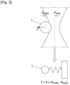
- the force applied to the particle is a linear function, and the optical trap can be compared to a simple spring system, which follows Hooke's law.
- the restoring optical force F is proportional to the distance from its equilibrium position, and the trap stiffness is proportional to the light intensity. Considering the motion range and the trap stiffness, three-dimensional pico-Newton resolution is reachable.
- optical trapping for quantitative force measurements, such as the strength of inter-molecular bonds, the stiffness of a cell membrane or intracellular measurements for micro-rheology.
- K [ K x , K y , K z ] is the trap stiffness where K x , K y , K z represent the stiffness in x, y, and z direction respectively. Therefore, the optical force F is obtained by measuring the particle's displacement from the equilibrium trap position.
- the determination of this position can be done by imagebased position detection where the images of video cameras are used to extract the information, or by interferometric methods where beam displacements after the laser passes through the sample are measured via quadrant photodiode QDP.
- the displacement in optical tweezers systems can be achieved by moving the platform or moving the laser beam, referred as passive actuation or active actuation.
- the laser direction is changed through active optical components.
- By rapidly deflecting the laser beam between several trap positions it is possible to trap several objects, in such a way that the objects do not have time to spread between two laser visits.
- These methods are referred as timeshared methods.
- active diffractive optical elements such as Spatial Light modulators (SLM)
- SLM Spatial Light modulators
- optical trapping configurations can be found in publications by GERENA EDISON ET AL., 1 April 2019, WO 2005/114151 A1 , or GERENA EDISON ET AL., 31 May 2020. 1
- the passive methods are usually used as the optical trap is maintained fixed, and only the trapped object position information is needed.
- the invention is to perform the position and thus the force measurement for all traps created by a three-dimensional multi-trap actuation system expanding the force measurements capabilities to several traps.
- the invention aims to provide a device for determining the position of a plurality of objects that are simultaneously trapped by a single laser beam.
- the device according to the invention comprises:
- the actuation system controls the three-dimensional position of the objects. As the image sensor is placed between the laser source and the actuation system and the actuation system is reversible, the image obtained by the image sensor is always aligned with the laser spot. Then by tracking the three-dimensional position of each object it is possible to obtain the three-dimensional force information of several traps similar as was performed in passive-actuation methods.
- the actuation system can include a deformable mirror for controlling the axial positions of the trapping points.
- the wording "axial" refers to the axis of the laser beam.
- the planar scanning mirror can be a mirror galvanometer.
- the deformable mirror can typically focus or defocus the laser beam axially.
- the device can comprise a system for passing the laser beam emitted by the laser source several times through the deformable mirror.
- the focalisation in the case of a converging configuration of the deformable mirror
- the defocalisation in the case of a diverging configuration of the deformable mirror
- the angle of the laser beam at the entrance of the microscope objective is increased (in the case of a diverging configuration of the deformable mirror) or decreased (in the case of a converging configuration of the deformable mirror).
- the axial position of the trapping points can be increased (in the case of a diverging configuration of the deformable mirror) or decreased (in the case of a converging configuration of the deformable mirror).
- the invention allows the high-speed motion control of the trapping points in a large working space.
- the light path is bidirectional, i.e. the path is independent from the propagation direction, and the optical efficiency is maximized. This property allows the simultaneous trapping of objects in the axial direction and the visualization of trapped objects in the axial plane, as the illumination light returns along the same path as the manipulation laser.
- the actuation axis workspace can be enlarged by using several "virtual" deformable mirrors in series.
- the idea is to pass the laser beam several times through the same deformable mirror using for instance a set of mirrors.
- the working space the number of traps that can be created and the maximum applicable force are increased. It could be used to simultaneously manipulated or stimulated several biological and synthetic objects in a large 3D working space.
- This actuation technique is also useful in different applications where the 3D orientation of microscopic objects (biological or synthetic) is needed, such as cell surgery applications (e.g. nuclear transplantation, embryo micro-injections, polar-body biopsy), 3D tomographic imaging of living samples, or microassembling in microfluidic devices.
- the system for passing the laser beam several times through the deformable mirror can comprise at least one set of two mirrors for guiding the laser beam between two successive passages of the laser beam on the deformable mirror.
- the system for passing the laser beam several times through the deformable mirror advantageously comprises between two consecutive passages of the laser beam through the deformable mirror an afocal system for conjugating said two consecutive passages of the laser beam through the deformable mirror.
- the afocal system can comprise two converging lenses.
- the actuation system can include a planar scanning mirror for controlling the planar positions of the trapping points.
- planar refers to a plan perpendicular to the axis of the laser beam.
- the planar scanning mirror can be a mirror galvanometer.
- the device advantageously comprises a first afocal system placed between the deformable mirror and the planar scanning mirror and a second afocal system placed between the planar scanning mirror and the microscope objective, for conjugating the deformable mirror and the planar scanning mirror with the entrance aperture of the microscope objective.
- the device can comprise a system for calculating the force on each trapped object as a function of the position of each of the trapped object determined by the camera.
- the force on the trapped object is the sum of the external forces that move the object from its equilibrium position, i.e the sum of the external forces that move the object with the exception of the force applied by the laser beam.
- the force and torque applied to a synthetic object with several objects attached to its body can be calculated as a function of the force F on each trapped object.
- the objects to be trapped can be biological objects, such as red blood cells and bacteria cells or synthetic objects such as optical robots (especially printed-design micro-structures with different types of end-effectors) which can be used to indirectly manipulate and measure forces.
- the objects to be trapped can be biological objects, microspheres or synthetic objects.
- Figure 3 illustrates a device 10 for determining the position of a plurality of objects 1 that are simultaneously trapped by a single laser beam 2 according to the invention.
- the device 10 comprises a laser source 5 which emits a laser beam 2.
- the laser source 5 can be a 1070 nm laser.
- the stiffness of the trap depends on the laser power, and the output laser power usually used can be from 100mW to 2W.
- the laser beam 2 passes through an actuation system for deflecting the laser beam 2 between several trapping positions.
- the generation of several simultaneously trapping points using a single laser source can be achieved using spatial or temporal sharing methods. Multiple stable trapping points can be created by rapidly deflecting a laser beam among a set of positions.
- the displacement in optical traps systems can be achieved by moving the platform or moving the laser beam, referred to as passive actuation or active actuation.
- the laser direction is changed through active optical components.
- By rapidly deflecting the laser beam between several trap positions it is possible to trap several objects, in such a way that the objects do not have time to spread between two laser visits.
- This method is referred to as timeshared method.
- active diffractive optical elements such as Spatial Light Modulators (SLM)
- SLM Spatial Light Modulators
- several traps can be dynamically controlled creating a number of diffraction spots at different positions. This method is referred to as spatial-shared method.
- a microscope objective 6 is used to focus the laser beam 2 coming from the actuation system on the trapping points and to image the trapped objects 1.
- the objects 1 of a sample 7 are disposed in a sample chamber 8 placed on a platform 9 (can be a three-dimensional nanostage).
- a light source 11 is used to lighten the sample.
- the light source can be a LED (light-emitting diode).
- the light 20 is focused on the sample 8 in the axial direction Z via a lens 12.
- the actuation system controls the three-dimensional position of the objects 1, i.e in the axial Z direction as well as in the planar X, Y directions. It includes a deformable mirror 13 and a galvanometer 14 which are used to control the axial Z and the planar X, Y positions of the trapping points respectively.
- the deformable mirror 13 which can focus or defocus the laser beam 2 is used on the Z axis.
- the deformable mirror 13 and the galvanometer 14 are positioned in a conjugate plane on the entrance aperture of the microscope objective 6. Hence, the laser beam 2 will pivot around the entrance aperture of the microscope objective 6 and retain the same degree of overfilling, independently of the angle or the degree of collimation of the incident beam 2, producing equally and stable traps.
- the deformable mirror 13 can be a microelectromechanical component with 111 actuators and 37 piston-tip-tilt segments with an update rate of more than 2 kHz.
- Each segment has 700 ⁇ m diameter while the array has an aperture of 3.5 mm and with a maximum dynamic range (Stroke) of 5.8 ⁇ m.
- Electrostatic actuation allows precise positioning of each segment with nanometer and microradian resolution (wavefront resolution ⁇ 15 nm rms).
- the mechanical step-response speed is less than 200 ⁇ s (10-90%) and has high reflectance (>99.9%).
- the segmented deformable mirror 13 can effectively create smooth shapes, and it is used to control the degree of collimation of the laser beam 2.
- This axial scan implies a very low mechanical inertia, hence the Z bandwidth is compatible with the galvanometer 14.
- the overall switching speed between three-dimensional trap position is the same order of magnitude of equivalent two-dimensional systems in the prior art. Thus, it is possible to obtain very stable traps without introducing any significant aberrations.
- the Gaussian laser beam (1070 nm) is guided into the inverted microscope 6 through the galvanometer 14, the deformable mirror 13, and standard optical elements.
- Two afocal systems f 1 , f 2 and f 3 , f 4 are preferably used to conjugate the two actuators 13, 14 with the entrance aperture of the microscope objective 6 and to expand the laser beam 2. It is expanded in order to overfill (20%) the objective entrance to improve the trapping efficiency.
- Figure 5 shows how the laser beam 2 will pivot around the microscope objective's entrance aperture for small movements of the mirror galvanometer 14 creating the motion of the optical trap in the optical plane and thus creating several trapping points 15.
- an image sensor 16 for determining the position of each of the trapped objects 1 is located between the laser source 5 and the actuation system 13, 14, more precisely between the laser source 5 and the deformable mirror 13, so that the light emitted by the light source 11 passes successively through the sample 7, the microscope objective 6, the actuation system 13, 14 and is then guided via a dichroic mirror 21 to the camera 16.
- the image sensor can be an event-based camera.
- the light pass is bidirectional, i.e. the path is independent from the propagation direction.
- the white light 20 reaches and goes through the actuation system 13, 14 in the exact opposite direction from the laser beam 2. In this way the image on the sensor 16 is always cantered on the laser spot. In this configuration, only one sensor receives the measurement of all the scanned points.
- This solution bypasses the problem of determining the center of the mobile laser in a multi-trap force measurement.
- a tradeoff between spatial and temporal resolution may remain, as the totality of pixels are used to determine the position of each trapped object, but the time to take the measurements depends on the number of created traps and the scanning frequency. In this way, it is for instance possible to arbitrarily position in a space three different traps, while the sensor receives the information from all the scanned points, thus measuring the position with respect to the laser of each trapped object, and finally extracting the information of external forces for each trap.
- Multi-trap force measurement will be also useful in the investigation of mechanotransduction, for example the cell adaptation to repetitive stimulations and clarify how cells change shape and control their migratory behavior.
- Optical robots 22 are especially printed-design micro-structures with different types of end-effectors, actuated in 6DoF (six degrees of freedom) by optical tweezers through spherical handles attached to its bodies ( figure 8 ).
- a six-axis force/torque measurement can be performed by combining the information of each trap.
- 6-DoF Optobots with a six-axis force sensor will allow the study of new biological interactions, such as the mechanism of Toxoplsama gondii. This latter requires mechanical work of translation and rotational twisting motion to complete cellular invasion, and therefore only characterizable with a six-axis force/torque sensor.
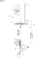
- a haptic interface 17 can be used.
- the user controls the three-dimensional position of the microrobot and feels the three-dimensional external forces F applied to it via a force sensor 18 that determines the force applied as explained above.
- a computer 19 makes it possible to have a visual perception and environment information to operators.
Landscapes
- Physics & Mathematics (AREA)
- Chemical & Material Sciences (AREA)
- General Physics & Mathematics (AREA)
- Analytical Chemistry (AREA)
- Optics & Photonics (AREA)
- Biochemistry (AREA)
- Life Sciences & Earth Sciences (AREA)
- General Health & Medical Sciences (AREA)
- Health & Medical Sciences (AREA)
- Immunology (AREA)
- Pathology (AREA)
- Dispersion Chemistry (AREA)
- Microscoopes, Condenser (AREA)
- Manipulator (AREA)
- Length Measuring Devices By Optical Means (AREA)
Description
- The present invention is related to a device for determining the position of a plurality of objects that are simultaneously trapped by a single laser beam. In particular, the device according to the invention makes it possible to determine the external forces applied to the objects.
- Optical tweezers (originally called single-beam gradient force trap) are scientific instruments that use a highly focused laser beam to provide an attractive or repulsive force (typically on the order of piconewtons), depending on the relative refractive index between particle and surrounding medium; these forces can be used to physically hold and move microscopic objects, in a manner similar to tweezers. They are able to trap and manipulate small particles, whose size is typically in microns, including dielectric and absorbing particles. Optical tweezers have been particularly successful in studying a variety of biological systems in recent years.
- As shown in
figure 1 andfigure 2 , optical tweezers are capable of manipulating nanometer and micron-sizeddielectric particles 1 by exerting extremely small forces via a highly focusedlaser beam 2 extending along an optical axis Z. Thebeam 2 is typically focused by sending it through a microscope objective. The narrowest point of the focused beam, known as the beam waist, contains a very strongelectric field gradient 3. Dielectric particles are attracted along the gradient to the region of strongest electric field, which is the center of the beam. The laser light also tends to apply a force on particles in the beam along the direction of beam propagation. This is due to conservation of momentum: photons that are absorbed or scattered by the tiny dielectric particle impart momentum to the dielectric particle. This is known as thescattering force 4 and results in the particle being displaced slightly downstream from the exact position of the beam waist, as seen infigure 1 . - In an optical trap, the tightly focused laser beam provides equilibrium position near the beam waist. When the
trapped objects 1 are laterally or axially displaced away from the equilibrium position, the optical forces act to pull it back towards the equilibrium position. For small displacements, the force applied to the particle is a linear function, and the optical trap can be compared to a simple spring system, which follows Hooke's law. In this model the restoring optical force F is proportional to the distance from its equilibrium position, and the trap stiffness is proportional to the light intensity. Considering the motion range and the trap stiffness, three-dimensional pico-Newton resolution is reachable. - This particularity has led to the use of optical trapping for quantitative force measurements, such as the strength of inter-molecular bonds, the stiffness of a cell membrane or intracellular measurements for micro-rheology.
- Force calibration of arbitrary objects with reasonable accuracy is still a challenge as the optical stiffness depends on several factors such as the material properties, the refractive index of both object and environment, the sizes and shapes of trapped objects etc. For these reasons, silicon or polystyrene microspheres are often used as a force probe to indirectly manipulate and sense the force during micromanipulation tasks. By using artificial microbeads which are uniform in material and shape, the optical force applied on the microbead can be obtained.
- For small displacements, the optical force can be described by a spring model:

- Where Plaser and Pprobe represent the laser and the
particle 1 position respectively. F is the three-dimensional optical force. K: [Kx, Ky, Kz ] is the trap stiffness where Kx, Ky, Kz represent the stiffness in x, y, and z direction respectively. Therefore, the optical force F is obtained by measuring the particle's displacement from the equilibrium trap position. - Well-established methods exist for precise stiffness calibration, as equipartition method and Stokes' drag method. Hence, force sensing directly stems from the capability to detect the position of the laser and the one of the trapped objects.
- The determination of this position can be done by imagebased position detection where the images of video cameras are used to extract the information, or by interferometric methods where beam displacements after the laser passes through the sample are measured via quadrant photodiode QDP.
- The displacement in optical tweezers systems can be achieved by moving the platform or moving the laser beam, referred as passive actuation or active actuation.
- In passive-actuation the incorporation of a motorized stage allows dynamic control of the sample chamber, while the manipulated object remains fixed on the trap.
- In active-actuation, the laser direction is changed through active optical components. In addition, it is possible to multiplex the trapping laser beam in order to simultaneously trap several objects using a unique laser source. By rapidly deflecting the laser beam between several trap positions, it is possible to trap several objects, in such a way that the objects do not have time to spread between two laser visits. These methods are referred as timeshared methods. Or by using active diffractive optical elements such as Spatial Light modulators (SLM), several traps can be dynamically controlled creating a number of diffraction spots at different positions, referred as spatial-shared methods.
- Examples of optical trapping configurations can be found in publications by
GERENA EDISON ET AL., 1 April 2019, WO 2005/114151 A1 , or GERENA EDISON ET AL., 31 May 2020. 1 - In quantitative force measurements with optical tweezers, the passive methods are usually used as the optical trap is maintained fixed, and only the trapped object position information is needed.
- The invention is to perform the position and thus the force measurement for all traps created by a three-dimensional multi-trap actuation system expanding the force measurements capabilities to several traps.
- To this end, the invention aims to provide a device for determining the position of a plurality of objects that are simultaneously trapped by a single laser beam.
- The device according to the invention comprises:
- a laser source for emitting a laser beam,
- an actuation system for a three-dimensional deflecting of the laser beam between several trapping points,
- a microscope objective for focusing the laser beam coming from the actuation system on the trapping points,
- a sample chamber including the objects to be trapped on the trapping points,
- a light source for lighten the sample chamber, and
- an image sensor (for instance a camera) for determining the position of each of the trapped objects, said image sensor being located between the laser source and the actuation system, so that the light emitted by the light source passes successively through the sample chamber, the microscope objective, the actuation system and the image sensor.
- The actuation system controls the three-dimensional position of the objects. As the image sensor is placed between the laser source and the actuation system and the actuation system is reversible, the image obtained by the image sensor is always aligned with the laser spot. Then by tracking the three-dimensional position of each object it is possible to obtain the three-dimensional force information of several traps similar as was performed in passive-actuation methods.
- The actuation system can include a deformable mirror for controlling the axial positions of the trapping points. The wording "axial" refers to the axis of the laser beam. The planar scanning mirror can be a mirror galvanometer.
- The deformable mirror can typically focus or defocus the laser beam axially.
- The device can comprise a system for passing the laser beam emitted by the laser source several times through the deformable mirror.
- Thus, by passing the laser beam several times through the same deformable mirror, the focalisation (in the case of a converging configuration of the deformable mirror) or the defocalisation (in the case of a diverging configuration of the deformable mirror) is amplified and therefore the angle of the laser beam at the entrance of the microscope objective is increased (in the case of a diverging configuration of the deformable mirror) or decreased (in the case of a converging configuration of the deformable mirror). Thus, the axial position of the trapping points can be increased (in the case of a diverging configuration of the deformable mirror) or decreased (in the case of a converging configuration of the deformable mirror). The invention allows the high-speed motion control of the trapping points in a large working space. As the device is still solely based on mirrors the light path is bidirectional, i.e. the path is independent from the propagation direction, and the optical efficiency is maximized. This property allows the simultaneous trapping of objects in the axial direction and the visualization of trapped objects in the axial plane, as the illumination light returns along the same path as the manipulation laser.
- Thus, the actuation axis workspace can be enlarged by using several "virtual" deformable mirrors in series. The idea is to pass the laser beam several times through the same deformable mirror using for instance a set of mirrors. By ensuring that virtual deformable mirrors are placed on conjugate planes of the entrance aperture of the objective, it is possible to increase considerably the workspace, while ensuring that the size of the laser beam diameter at the entrance aperture of the objective remain the same, regardless the degree of convergence or divergence of the laser beam.
- The working space, the number of traps that can be created and the maximum applicable force are increased. It could be used to simultaneously manipulated or stimulated several biological and synthetic objects in a large 3D working space. This actuation technique is also useful in different applications where the 3D orientation of microscopic objects (biological or synthetic) is needed, such as cell surgery applications (e.g. nuclear transplantation, embryo micro-injections, polar-body biopsy), 3D tomographic imaging of living samples, or microassembling in microfluidic devices.
- The system for passing the laser beam several times through the deformable mirror can comprise at least one set of two mirrors for guiding the laser beam between two successive passages of the laser beam on the deformable mirror.
- The system for passing the laser beam several times through the deformable mirror advantageously comprises between two consecutive passages of the laser beam through the deformable mirror an afocal system for conjugating said two consecutive passages of the laser beam through the deformable mirror.
- The afocal system can comprise two converging lenses.
- The actuation system can include a planar scanning mirror for controlling the planar positions of the trapping points. The wording "planar" refers to a plan perpendicular to the axis of the laser beam. The planar scanning mirror can be a mirror galvanometer.
- The device advantageously comprises a first afocal system placed between the deformable mirror and the planar scanning mirror and a second afocal system placed between the planar scanning mirror and the microscope objective, for conjugating the deformable mirror and the planar scanning mirror with the entrance aperture of the microscope objective.
- The device can comprise a system for calculating the force on each trapped object as a function of the position of each of the trapped object determined by the camera.
- The force F on each trapped object can be calculated by the system using the optical force model:

- The force on the trapped object is the sum of the external forces that move the object from its equilibrium position, i.e the sum of the external forces that move the object with the exception of the force applied by the laser beam.
- The force and torque applied to a synthetic object with several objects attached to its body, can be calculated as a function of the force F on each trapped object.
- The objects to be trapped can be biological objects, such as red blood cells and bacteria cells or synthetic objects such as optical robots (especially printed-design micro-structures with different types of end-effectors) which can be used to indirectly manipulate and measure forces. Thus, the objects to be trapped can be biological objects, microspheres or synthetic objects.
- Other aims, features and advantages of the invention will emerge from reading the following description, given purely by way of non-limiting example, and with reference to the accompanying drawings in which:
-
Figure 1 , previously described, is a schematic view of an optical tweezer, -
Figure 2 , previously described, illustrates the determination of the external force applied to the object trapped in the optical tweezer offigure 1 , -
Figure 3 schematically represents a device for determining the position of trapped objects in optical tweezers according to the invention, -
Figure 4 is a diagram illustrating a haptic interface associated with a device according to the invention, -
Figure 5 schematically illustrates a mirror galvanometer used in the device according to the invention, -
Figure 6 and Figure 7 schematically illustrate a deformable mirror used in the device according to the invention, and -
Figure 8 is a diagram illustrating an optical robot associated with a device according to the invention. -
Figure 3 illustrates adevice 10 for determining the position of a plurality ofobjects 1 that are simultaneously trapped by asingle laser beam 2 according to the invention. - The
device 10 comprises alaser source 5 which emits alaser beam 2. Thelaser source 5 can be a 1070 nm laser. The stiffness of the trap depends on the laser power, and the output laser power usually used can be from 100mW to 2W. - The
laser beam 2 passes through an actuation system for deflecting thelaser beam 2 between several trapping positions. The generation of several simultaneously trapping points using a single laser source can be achieved using spatial or temporal sharing methods. Multiple stable trapping points can be created by rapidly deflecting a laser beam among a set of positions. The displacement in optical traps systems can be achieved by moving the platform or moving the laser beam, referred to as passive actuation or active actuation. - In passive actuation, the incorporation of a motorized stage allows dynamic control of the sample chamber, while the manipulated object remains fixed on the trap.
- In active actuation, the laser direction is changed through active optical components. In addition, it is possible to multiplex the trapping laser beam in order to simultaneously trap several objects using a unique laser source. By rapidly deflecting the laser beam between several trap positions, it is possible to trap several objects, in such a way that the objects do not have time to spread between two laser visits. This method is referred to as timeshared method. Or by using active diffractive optical elements such as Spatial Light Modulators (SLM), several traps can be dynamically controlled creating a number of diffraction spots at different positions. This method is referred to as spatial-shared method.
- A
microscope objective 6 is used to focus thelaser beam 2 coming from the actuation system on the trapping points and to image the trapped objects 1. Theobjects 1 of asample 7 are disposed in asample chamber 8 placed on a platform 9 (can be a three-dimensional nanostage). - A
light source 11 is used to lighten the sample. The light source can be a LED (light-emitting diode). - The light 20 is focused on the
sample 8 in the axial direction Z via alens 12. - The actuation system controls the three-dimensional position of the
objects 1, i.e in the axial Z direction as well as in the planar X, Y directions. It includes adeformable mirror 13 and agalvanometer 14 which are used to control the axial Z and the planar X, Y positions of the trapping points respectively. - The
deformable mirror 13 which can focus or defocus thelaser beam 2 is used on the Z axis. Thedeformable mirror 13 and thegalvanometer 14 are positioned in a conjugate plane on the entrance aperture of themicroscope objective 6. Hence, thelaser beam 2 will pivot around the entrance aperture of themicroscope objective 6 and retain the same degree of overfilling, independently of the angle or the degree of collimation of theincident beam 2, producing equally and stable traps. - The
deformable mirror 13 can be a microelectromechanical component with 111 actuators and 37 piston-tip-tilt segments with an update rate of more than 2 kHz. Each segment has 700 µm diameter while the array has an aperture of 3.5 mm and with a maximum dynamic range (Stroke) of 5.8 µm. Electrostatic actuation allows precise positioning of each segment with nanometer and microradian resolution (wavefront resolution <15 nm rms). The mechanical step-response speed is less than 200 µs (10-90%) and has high reflectance (>99.9%). - The segmented
deformable mirror 13 can effectively create smooth shapes, and it is used to control the degree of collimation of thelaser beam 2. By synchronizing the orientation of themirror galvanometer 14 and the motion of thedeformable mirror 13, it is possible to displace the focal spot laterally and axially while maintaining the diffraction-limited performance. This axial scan implies a very low mechanical inertia, hence the Z bandwidth is compatible with thegalvanometer 14. The overall switching speed between three-dimensional trap position is the same order of magnitude of equivalent two-dimensional systems in the prior art. Thus, it is possible to obtain very stable traps without introducing any significant aberrations. - The Gaussian laser beam (1070 nm) is guided into the
inverted microscope 6 through thegalvanometer 14, thedeformable mirror 13, and standard optical elements. Two afocal systems f1, f2 and f3, f4 are preferably used to conjugate the twoactuators microscope objective 6 and to expand thelaser beam 2. It is expanded in order to overfill (20%) the objective entrance to improve the trapping efficiency. -
Figure 5 shows how thelaser beam 2 will pivot around the microscope objective's entrance aperture for small movements of themirror galvanometer 14 creating the motion of the optical trap in the optical plane and thus creating several trapping points 15. - It is shown the effect of focusing (
Figure 6 ) or defocusing (Figure 7 ) thedeformable mirror 13 to change the Z position of the trapping points 15. The size of thebeam 2 at the objective's entrance aperture remains the same, regardless of the degree of collimation of the incident beam. - According to the invention, an
image sensor 16 for determining the position of each of the trapped objects 1 is located between thelaser source 5 and theactuation system laser source 5 and thedeformable mirror 13, so that the light emitted by thelight source 11 passes successively through thesample 7, themicroscope objective 6, theactuation system dichroic mirror 21 to thecamera 16. The image sensor can be an event-based camera. - Due to the fact that the
actuation system camera 16, it is possible to track the position of the trappedobjects 1 by looking at onetrapping point 15 at a time, where it three-dimensional position is, and as theobjects 1 are always maintained in the center of the field of view of thecamera 16. - Placing the
camera 16 between thelaser source 5 and theactuation system white light 20 reaches and goes through theactuation system laser beam 2. In this way the image on thesensor 16 is always cantered on the laser spot. In this configuration, only one sensor receives the measurement of all the scanned points. By synchronizing the multi-trap actuation technique and the event-based camera 16 (or other cameras), it will be possible to differentiate events (or frames) coming fromdifferent traps 15. This solution bypasses the problem of determining the center of the mobile laser in a multi-trap force measurement. A tradeoff between spatial and temporal resolution may remain, as the totality of pixels are used to determine the position of each trapped object, but the time to take the measurements depends on the number of created traps and the scanning frequency. In this way, it is for instance possible to arbitrarily position in a space three different traps, while the sensor receives the information from all the scanned points, thus measuring the position with respect to the laser of each trapped object, and finally extracting the information of external forces for each trap. - This ability to measure force at multiple three-dimensional locations simultaneously is important in many biomechanical studies, such as characterizing the stiffness of the membrane of a cell at multiple points during a fusion phase or measure the stiffness at different cells simultaneously. Multi-trap force measurement will be also useful in the investigation of mechanotransduction, for example the cell adaptation to repetitive stimulations and clarify how cells change shape and control their migratory behavior.
-
Optical robots 22 are especially printed-design micro-structures with different types of end-effectors, actuated in 6DoF (six degrees of freedom) by optical tweezers through spherical handles attached to its bodies (figure 8 ). - By measuring the three-dimensional force for each handle of the robots, a six-axis force/torque measurement can be performed by combining the information of each trap. These 6-DoF Optobots with a six-axis force sensor will allow the study of new biological interactions, such as the mechanism of Toxoplsama gondii. This latter requires mechanical work of translation and rotational twisting motion to complete cellular invasion, and therefore only characterizable with a six-axis force/torque sensor.
- As illustrated in
figure 4 , ahaptic interface 17 can be used. The user controls the three-dimensional position of the microrobot and feels the three-dimensional external forces F applied to it via aforce sensor 18 that determines the force applied as explained above. Acomputer 19 makes it possible to have a visual perception and environment information to operators.
Claims (10)
- Device (10) for determining the position of a plurality of objects (1) that are simultaneously trapped by a single laser beam (2), the device (10) comprising:- a laser source (5) for emitting a laser beam (2),- an actuation system (13, 14) for a three-dimensional deflecting of the laser beam (2) between several trapping points (15),- a microscope objective (6) for focusing the laser beam (2) coming from the actuation system (13, 14) on the trapping points (15),- a sample chamber (8) including the objects (1) to be trapped on the trapping points (15),- a light source (11) for lighten the sample chamber (8), and- an image sensor (16) for determining the position of each of the trapped objects (1),characterized in that said image sensor (16) is located between the laser source (5) and the actuation system (13, 14), so that the light (20) emitted by the light source (11) passes successively through the sample chamber (8), the microscope objective (6), the actuation system (13, 14) and the image sensor (16).
- Device (10) according to claim 1, characterized in that the actuation system (13, 14) includes a deformable mirror (13) for controlling the axial (Z) positions of the trapping points (15).
- Device (10) according to claim 2, characterized in that the deformable mirror (13) can focus or defocus the laser beam axially.
- Device (10) according to claim 2, characterized in that it comprises a system for passing the laser beam (2) emitted by the laser source (5) several times through the deformable mirror (13).
- Device (10) according to any one of claims 1 to 4, characterized in that the actuation system (13, 14) includes a planar scanning mirror (14) for controlling the planar (X, Y) positions of the trapping points (15).
- Device (10) according to claims 2 and 5, characterized it comprises a first afocal system (f1, f2) placed between the deformable mirror (13) and the mirror galvanometer (14) and a second afocal system (f1, f2) placed between the mirror galvanometer (14) and the microscope objective (6), for conjugating the deformable mirror (13) and the mirror galvanometer (14) with the entrance aperture of the microscope objective (6).
- Device (10) according to any one of claims 1 to 6, characterized in that it comprises a system (18) for calculating the force (F) on each trapped object (1) as a function of the position of each of the trapped object (1) determined by the camera (16).
- Device (10) according to claim 7, characterized in that the force F on each trapped object is calculated by the system (18) using the optical force model : F = K* (Plaser - Pprobe) , wherein Plaser - Pprobe represents the displacement between the laser position and the position of the trapped object, K being the stiffness of the trap.
- Device (10) according to claim 7 or 8, characterized in that the force and torque applied to a synthetic object (22) with several objects (1) attached to its body, is calculated as a function of the force (F) on each trapped object (1).
- Device (10) according to any one of claims 1 to 9, characterized in that the objects (1) to be trapped are biological objects, microspheres or synthetic objects.
Applications Claiming Priority (1)
| Application Number | Priority Date | Filing Date | Title |
|---|---|---|---|
| PCT/IB2020/001125 WO2022090761A1 (en) | 2020-10-29 | 2020-10-29 | Device for determining the position of trapped objects in optical tweezers |
Publications (2)
| Publication Number | Publication Date |
|---|---|
| EP4237824A1 EP4237824A1 (en) | 2023-09-06 |
| EP4237824B1 true EP4237824B1 (en) | 2024-12-04 |
Family
ID=74858475
Family Applications (1)
| Application Number | Title | Priority Date | Filing Date |
|---|---|---|---|
| EP20861969.2A Active EP4237824B1 (en) | 2020-10-29 | 2020-10-29 | Device for determining the position of trapped objects in optical tweezers |
Country Status (5)
| Country | Link |
|---|---|
| US (1) | US12265012B2 (en) |
| EP (1) | EP4237824B1 (en) |
| JP (1) | JP7623481B2 (en) |
| ES (1) | ES3013997T3 (en) |
| WO (1) | WO2022090761A1 (en) |
Families Citing this family (4)
| Publication number | Priority date | Publication date | Assignee | Title |
|---|---|---|---|---|
| EP4237824B1 (en) | 2020-10-29 | 2024-12-04 | Sorbonne Université | Device for determining the position of trapped objects in optical tweezers |
| CN116068746B (en) * | 2022-12-14 | 2025-09-09 | 厦门理工学院 | Consistency control method, device, equipment and storage medium for holographic optical tweezers |
| WO2025074135A1 (en) | 2023-10-06 | 2025-04-10 | Sorbonne Universite (Su) | A microfluidic chip, apparatus and method for in vitro fertilization |
| WO2025074134A1 (en) | 2023-10-06 | 2025-04-10 | Sorbonne Universite (Su) | Microstructure and method for capturing and manipulating a target in a fluid medium |
Family Cites Families (12)
| Publication number | Priority date | Publication date | Assignee | Title |
|---|---|---|---|---|
| JP4491882B2 (en) | 2000-01-06 | 2010-06-30 | 株式会社ニコン | Microscope using deep ultraviolet light as light source |
| US20080316575A1 (en) | 2002-08-01 | 2008-12-25 | The University Of Chicago., | Aberration correction of optical traps |
| JP3887684B2 (en) | 2003-01-31 | 2007-02-28 | 独立行政法人産業技術総合研究所 | Attitude control device and attitude control method for minute objects |
| JP4468684B2 (en) | 2003-12-05 | 2010-05-26 | オリンパス株式会社 | Scanning confocal microscope |
| JP2005337730A (en) | 2004-05-24 | 2005-12-08 | Nara Institute Of Science & Technology | Measuring system |
| JP4786291B2 (en) | 2005-10-19 | 2011-10-05 | 浜松ホトニクス株式会社 | Optical tweezers |
| JP5686408B2 (en) | 2011-01-31 | 2015-03-18 | 独立行政法人産業技術総合研究所 | Fine particle array method and apparatus |
| JP5979536B2 (en) | 2012-05-09 | 2016-08-24 | 国立研究開発法人産業技術総合研究所 | Three-dimensional operation device for minute objects |
| NL2014262B1 (en) * | 2015-02-09 | 2016-10-13 | Stichting Vu | Apparatus and method for controlling a plurality of optical traps. |
| JP2016218282A (en) | 2015-05-21 | 2016-12-22 | 国立研究開発法人産業技術総合研究所 | Fine particle array creation and orientation control method |
| WO2019195785A1 (en) * | 2018-04-05 | 2019-10-10 | Cornell University | Image-based measurements of force in a dual optical trap |
| EP4237824B1 (en) | 2020-10-29 | 2024-12-04 | Sorbonne Université | Device for determining the position of trapped objects in optical tweezers |
-
2020
- 2020-10-29 EP EP20861969.2A patent/EP4237824B1/en active Active
- 2020-10-29 WO PCT/IB2020/001125 patent/WO2022090761A1/en not_active Ceased
- 2020-10-29 US US18/250,514 patent/US12265012B2/en active Active
- 2020-10-29 JP JP2023525105A patent/JP7623481B2/en active Active
- 2020-10-29 ES ES20861969T patent/ES3013997T3/en active Active
Also Published As
| Publication number | Publication date |
|---|---|
| EP4237824A1 (en) | 2023-09-06 |
| US20230400402A1 (en) | 2023-12-14 |
| ES3013997T3 (en) | 2025-04-16 |
| US12265012B2 (en) | 2025-04-01 |
| JP2023549066A (en) | 2023-11-22 |
| JP7623481B2 (en) | 2025-01-28 |
| WO2022090761A1 (en) | 2022-05-05 |
Similar Documents
| Publication | Publication Date | Title |
|---|---|---|
| US12265012B2 (en) | Device for determining the position of trapped objects in optical tweezers | |
| EP1864176B1 (en) | Optical manipulation system using a plurality of optical traps | |
| JP6916963B2 (en) | Modular objective assembly with movable laser beam | |
| Gerena et al. | High-bandwidth 3-D multitrap actuation technique for 6-DoF real-time control of optical robots | |
| US8921765B2 (en) | System for manipulating and optically targeting micro objects | |
| NL2038334B1 (en) | A method for controlling sperm morphology and motion | |
| JP5979536B2 (en) | Three-dimensional operation device for minute objects | |
| US7982194B2 (en) | Single nanoparticle tracking spectroscopic microscope | |
| Oddershede et al. | Optical tweezers: probing biological surfaces | |
| Tanikawa et al. | Development of vision system for two-fingered micro manipulation | |
| JP3887684B2 (en) | Attitude control device and attitude control method for minute objects | |
| Gerena et al. | 3D force-feedback optical tweezers for experimental biology | |
| Dagalakis et al. | Micro-mirror array control of optical tweezer trapping beams | |
| Gerena | 6-DoF Optical-driven Micro-robots with Force Feedback Capabilities for Interactive Bio-manipulation | |
| Gorecki et al. | On-chip scanning confocal microscope with 3D MEMS scanner and VCSEL feedback detection | |
| KR102138930B1 (en) | Method for measuring rheological characteristics of non-spherical particles | |
| Phillips et al. | Fashioning microscopic tools | |
| Hayes | OPTICAL TWEEZERS AS A TOOL FOR MICRO-SCALE PARTICLE MANIPULATION AND MEASUREMENT | |
| Ohara et al. | Real-time 3D measurement system for micro-manipulation | |
| Shimada et al. | Mechanical properties analyzer for nano-size protein with optically driven nano-beam | |
| Obinata et al. | Vision systems: applications | |
| Agnus et al. | Architecture of a micromanipulation station | |
| WO2022164873A1 (en) | Fiber optical tweezers | |
| Nectoux et al. | Overview of microgrippers and design of a micromanipulation station based on a MMOC microgripper | |
| Onda et al. | Robotic approach to multi-beam optical tweezers with computer generated hologram |
Legal Events
| Date | Code | Title | Description |
|---|---|---|---|
| STAA | Information on the status of an ep patent application or granted ep patent |
Free format text: STATUS: UNKNOWN |
|
| STAA | Information on the status of an ep patent application or granted ep patent |
Free format text: STATUS: THE INTERNATIONAL PUBLICATION HAS BEEN MADE |
|
| PUAI | Public reference made under article 153(3) epc to a published international application that has entered the european phase |
Free format text: ORIGINAL CODE: 0009012 |
|
| STAA | Information on the status of an ep patent application or granted ep patent |
Free format text: STATUS: REQUEST FOR EXAMINATION WAS MADE |
|
| 17P | Request for examination filed |
Effective date: 20230324 |
|
| AK | Designated contracting states |
Kind code of ref document: A1 Designated state(s): AL AT BE BG CH CY CZ DE DK EE ES FI FR GB GR HR HU IE IS IT LI LT LU LV MC MK MT NL NO PL PT RO RS SE SI SK SM TR |
|
| DAV | Request for validation of the european patent (deleted) | ||
| DAX | Request for extension of the european patent (deleted) | ||
| GRAP | Despatch of communication of intention to grant a patent |
Free format text: ORIGINAL CODE: EPIDOSNIGR1 |
|
| STAA | Information on the status of an ep patent application or granted ep patent |
Free format text: STATUS: GRANT OF PATENT IS INTENDED |
|
| RIC1 | Information provided on ipc code assigned before grant |
Ipc: G01N 15/1404 20240101ALI20240517BHEP Ipc: G02B 26/10 20060101ALI20240517BHEP Ipc: G21K 1/00 20060101ALI20240517BHEP Ipc: G02B 26/08 20060101ALI20240517BHEP Ipc: G02B 21/36 20060101ALI20240517BHEP Ipc: G02B 21/00 20060101ALI20240517BHEP Ipc: G02B 21/32 20060101ALI20240517BHEP Ipc: G01N 15/14 20060101ALI20240517BHEP Ipc: G01N 15/10 20060101AFI20240517BHEP |
|
| INTG | Intention to grant announced |
Effective date: 20240607 |
|
| GRAS | Grant fee paid |
Free format text: ORIGINAL CODE: EPIDOSNIGR3 |
|
| GRAA | (expected) grant |
Free format text: ORIGINAL CODE: 0009210 |
|
| STAA | Information on the status of an ep patent application or granted ep patent |
Free format text: STATUS: THE PATENT HAS BEEN GRANTED |
|
| AK | Designated contracting states |
Kind code of ref document: B1 Designated state(s): AL AT BE BG CH CY CZ DE DK EE ES FI FR GB GR HR HU IE IS IT LI LT LU LV MC MK MT NL NO PL PT RO RS SE SI SK SM TR |
|
| REG | Reference to a national code |
Ref country code: CH Ref legal event code: EP |
|
| REG | Reference to a national code |
Ref country code: DE Ref legal event code: R096 Ref document number: 602020042716 Country of ref document: DE |
|
| REG | Reference to a national code |
Ref country code: IE Ref legal event code: FG4D |
|
| REG | Reference to a national code |
Ref country code: LT Ref legal event code: MG9D |
|
| REG | Reference to a national code |
Ref country code: NL Ref legal event code: MP Effective date: 20241204 |
|
| PG25 | Lapsed in a contracting state [announced via postgrant information from national office to epo] |
Ref country code: HR Free format text: LAPSE BECAUSE OF FAILURE TO SUBMIT A TRANSLATION OF THE DESCRIPTION OR TO PAY THE FEE WITHIN THE PRESCRIBED TIME-LIMIT Effective date: 20241204 |
|
| PG25 | Lapsed in a contracting state [announced via postgrant information from national office to epo] |
Ref country code: FI Free format text: LAPSE BECAUSE OF FAILURE TO SUBMIT A TRANSLATION OF THE DESCRIPTION OR TO PAY THE FEE WITHIN THE PRESCRIBED TIME-LIMIT Effective date: 20241204 |
|
| PG25 | Lapsed in a contracting state [announced via postgrant information from national office to epo] |
Ref country code: BG Free format text: LAPSE BECAUSE OF FAILURE TO SUBMIT A TRANSLATION OF THE DESCRIPTION OR TO PAY THE FEE WITHIN THE PRESCRIBED TIME-LIMIT Effective date: 20241204 |
|
| REG | Reference to a national code |
Ref country code: ES Ref legal event code: FG2A Ref document number: 3013997 Country of ref document: ES Kind code of ref document: T3 Effective date: 20250416 |
|
| PG25 | Lapsed in a contracting state [announced via postgrant information from national office to epo] |
Ref country code: NO Free format text: LAPSE BECAUSE OF FAILURE TO SUBMIT A TRANSLATION OF THE DESCRIPTION OR TO PAY THE FEE WITHIN THE PRESCRIBED TIME-LIMIT Effective date: 20250304 |
|
| PG25 | Lapsed in a contracting state [announced via postgrant information from national office to epo] |
Ref country code: LV Free format text: LAPSE BECAUSE OF FAILURE TO SUBMIT A TRANSLATION OF THE DESCRIPTION OR TO PAY THE FEE WITHIN THE PRESCRIBED TIME-LIMIT Effective date: 20241204 Ref country code: GR Free format text: LAPSE BECAUSE OF FAILURE TO SUBMIT A TRANSLATION OF THE DESCRIPTION OR TO PAY THE FEE WITHIN THE PRESCRIBED TIME-LIMIT Effective date: 20250305 |
|
| PG25 | Lapsed in a contracting state [announced via postgrant information from national office to epo] |
Ref country code: RS Free format text: LAPSE BECAUSE OF FAILURE TO SUBMIT A TRANSLATION OF THE DESCRIPTION OR TO PAY THE FEE WITHIN THE PRESCRIBED TIME-LIMIT Effective date: 20250304 |
|
| PG25 | Lapsed in a contracting state [announced via postgrant information from national office to epo] |
Ref country code: NL Free format text: LAPSE BECAUSE OF FAILURE TO SUBMIT A TRANSLATION OF THE DESCRIPTION OR TO PAY THE FEE WITHIN THE PRESCRIBED TIME-LIMIT Effective date: 20241204 |
|
| REG | Reference to a national code |
Ref country code: AT Ref legal event code: MK05 Ref document number: 1748649 Country of ref document: AT Kind code of ref document: T Effective date: 20241204 |
|
| PG25 | Lapsed in a contracting state [announced via postgrant information from national office to epo] |
Ref country code: SM Free format text: LAPSE BECAUSE OF FAILURE TO SUBMIT A TRANSLATION OF THE DESCRIPTION OR TO PAY THE FEE WITHIN THE PRESCRIBED TIME-LIMIT Effective date: 20241204 |
|
| PG25 | Lapsed in a contracting state [announced via postgrant information from national office to epo] |
Ref country code: PL Free format text: LAPSE BECAUSE OF FAILURE TO SUBMIT A TRANSLATION OF THE DESCRIPTION OR TO PAY THE FEE WITHIN THE PRESCRIBED TIME-LIMIT Effective date: 20241204 |
|
| PG25 | Lapsed in a contracting state [announced via postgrant information from national office to epo] |
Ref country code: IS Free format text: LAPSE BECAUSE OF FAILURE TO SUBMIT A TRANSLATION OF THE DESCRIPTION OR TO PAY THE FEE WITHIN THE PRESCRIBED TIME-LIMIT Effective date: 20250404 |
|
| PG25 | Lapsed in a contracting state [announced via postgrant information from national office to epo] |
Ref country code: PT Free format text: LAPSE BECAUSE OF FAILURE TO SUBMIT A TRANSLATION OF THE DESCRIPTION OR TO PAY THE FEE WITHIN THE PRESCRIBED TIME-LIMIT Effective date: 20250404 |
|
| PG25 | Lapsed in a contracting state [announced via postgrant information from national office to epo] |
Ref country code: EE Free format text: LAPSE BECAUSE OF FAILURE TO SUBMIT A TRANSLATION OF THE DESCRIPTION OR TO PAY THE FEE WITHIN THE PRESCRIBED TIME-LIMIT Effective date: 20241204 |
|
| PG25 | Lapsed in a contracting state [announced via postgrant information from national office to epo] |
Ref country code: AT Free format text: LAPSE BECAUSE OF FAILURE TO SUBMIT A TRANSLATION OF THE DESCRIPTION OR TO PAY THE FEE WITHIN THE PRESCRIBED TIME-LIMIT Effective date: 20241204 Ref country code: RO Free format text: LAPSE BECAUSE OF FAILURE TO SUBMIT A TRANSLATION OF THE DESCRIPTION OR TO PAY THE FEE WITHIN THE PRESCRIBED TIME-LIMIT Effective date: 20241204 |
|
| PG25 | Lapsed in a contracting state [announced via postgrant information from national office to epo] |
Ref country code: SK Free format text: LAPSE BECAUSE OF FAILURE TO SUBMIT A TRANSLATION OF THE DESCRIPTION OR TO PAY THE FEE WITHIN THE PRESCRIBED TIME-LIMIT Effective date: 20241204 |
|
| REG | Reference to a national code |
Ref country code: DE Ref legal event code: R097 Ref document number: 602020042716 Country of ref document: DE |
|
| PG25 | Lapsed in a contracting state [announced via postgrant information from national office to epo] |
Ref country code: SE Free format text: LAPSE BECAUSE OF FAILURE TO SUBMIT A TRANSLATION OF THE DESCRIPTION OR TO PAY THE FEE WITHIN THE PRESCRIBED TIME-LIMIT Effective date: 20241204 |
|
| PG25 | Lapsed in a contracting state [announced via postgrant information from national office to epo] |
Ref country code: DK Free format text: LAPSE BECAUSE OF FAILURE TO SUBMIT A TRANSLATION OF THE DESCRIPTION OR TO PAY THE FEE WITHIN THE PRESCRIBED TIME-LIMIT Effective date: 20241204 |
|
| PLBE | No opposition filed within time limit |
Free format text: ORIGINAL CODE: 0009261 |
|
| STAA | Information on the status of an ep patent application or granted ep patent |
Free format text: STATUS: NO OPPOSITION FILED WITHIN TIME LIMIT |
|
| 26N | No opposition filed |
Effective date: 20250905 |
|
| PGFP | Annual fee paid to national office [announced via postgrant information from national office to epo] |
Ref country code: DE Payment date: 20251126 Year of fee payment: 6 |
|
| PGFP | Annual fee paid to national office [announced via postgrant information from national office to epo] |
Ref country code: GB Payment date: 20251029 Year of fee payment: 6 |
|
| PGFP | Annual fee paid to national office [announced via postgrant information from national office to epo] |
Ref country code: IT Payment date: 20251029 Year of fee payment: 6 |
|
| PGFP | Annual fee paid to national office [announced via postgrant information from national office to epo] |
Ref country code: FR Payment date: 20251030 Year of fee payment: 6 |
|
| PGFP | Annual fee paid to national office [announced via postgrant information from national office to epo] |
Ref country code: CZ Payment date: 20251023 Year of fee payment: 6 |
|
| PGFP | Annual fee paid to national office [announced via postgrant information from national office to epo] |
Ref country code: ES Payment date: 20260127 Year of fee payment: 6 |