EP4236524A1 - Secondary cell activation method, apparatus, device, and storage medium - Google Patents
Secondary cell activation method, apparatus, device, and storage medium Download PDFInfo
- Publication number
- EP4236524A1 EP4236524A1 EP20958239.4A EP20958239A EP4236524A1 EP 4236524 A1 EP4236524 A1 EP 4236524A1 EP 20958239 A EP20958239 A EP 20958239A EP 4236524 A1 EP4236524 A1 EP 4236524A1
- Authority
- EP
- European Patent Office
- Prior art keywords
- reference signal
- time domain
- domain position
- secondary cell
- activation signaling
- Prior art date
- Legal status (The legal status is an assumption and is not a legal conclusion. Google has not performed a legal analysis and makes no representation as to the accuracy of the status listed.)
- Granted
Links
Images


Classifications
-
- H—ELECTRICITY
- H04—ELECTRIC COMMUNICATION TECHNIQUE
- H04L—TRANSMISSION OF DIGITAL INFORMATION, e.g. TELEGRAPHIC COMMUNICATION
- H04L5/00—Arrangements affording multiple use of the transmission path
- H04L5/0091—Signalling for the administration of the divided path, e.g. signalling of configuration information
- H04L5/0096—Indication of changes in allocation
- H04L5/0098—Signalling of the activation or deactivation of component carriers, subcarriers or frequency bands
-
- H—ELECTRICITY
- H04—ELECTRIC COMMUNICATION TECHNIQUE
- H04L—TRANSMISSION OF DIGITAL INFORMATION, e.g. TELEGRAPHIC COMMUNICATION
- H04L5/00—Arrangements affording multiple use of the transmission path
- H04L5/0091—Signalling for the administration of the divided path, e.g. signalling of configuration information
- H04L5/0096—Indication of changes in allocation
-
- H—ELECTRICITY
- H04—ELECTRIC COMMUNICATION TECHNIQUE
- H04W—WIRELESS COMMUNICATION NETWORKS
- H04W72/00—Local resource management
- H04W72/04—Wireless resource allocation
-
- H—ELECTRICITY
- H04—ELECTRIC COMMUNICATION TECHNIQUE
- H04W—WIRELESS COMMUNICATION NETWORKS
- H04W72/00—Local resource management
- H04W72/04—Wireless resource allocation
- H04W72/044—Wireless resource allocation based on the type of the allocated resource
- H04W72/0446—Resources in time domain, e.g. slots or frames
-
- H—ELECTRICITY
- H04—ELECTRIC COMMUNICATION TECHNIQUE
- H04W—WIRELESS COMMUNICATION NETWORKS
- H04W72/00—Local resource management
- H04W72/20—Control channels or signalling for resource management
- H04W72/23—Control channels or signalling for resource management in the downlink direction of a wireless link, i.e. towards a terminal
-
- H—ELECTRICITY
- H04—ELECTRIC COMMUNICATION TECHNIQUE
- H04W—WIRELESS COMMUNICATION NETWORKS
- H04W72/00—Local resource management
- H04W72/20—Control channels or signalling for resource management
- H04W72/23—Control channels or signalling for resource management in the downlink direction of a wireless link, i.e. towards a terminal
- H04W72/231—Control channels or signalling for resource management in the downlink direction of a wireless link, i.e. towards a terminal the control data signalling from the layers above the physical layer, e.g. RRC or MAC-CE signalling
-
- H—ELECTRICITY
- H04—ELECTRIC COMMUNICATION TECHNIQUE
- H04W—WIRELESS COMMUNICATION NETWORKS
- H04W72/00—Local resource management
- H04W72/20—Control channels or signalling for resource management
- H04W72/23—Control channels or signalling for resource management in the downlink direction of a wireless link, i.e. towards a terminal
- H04W72/232—Control channels or signalling for resource management in the downlink direction of a wireless link, i.e. towards a terminal the control data signalling from the physical layer, e.g. DCI signalling
-
- H—ELECTRICITY
- H04—ELECTRIC COMMUNICATION TECHNIQUE
- H04L—TRANSMISSION OF DIGITAL INFORMATION, e.g. TELEGRAPHIC COMMUNICATION
- H04L5/00—Arrangements affording multiple use of the transmission path
- H04L5/0001—Arrangements for dividing the transmission path
- H04L5/0003—Two-dimensional division
- H04L5/0005—Time-frequency
- H04L5/0007—Time-frequency the frequencies being orthogonal, e.g. OFDM(A) or DMT
- H04L5/001—Time-frequency the frequencies being orthogonal, e.g. OFDM(A) or DMT the frequencies being arranged in component carriers
-
- H—ELECTRICITY
- H04—ELECTRIC COMMUNICATION TECHNIQUE
- H04L—TRANSMISSION OF DIGITAL INFORMATION, e.g. TELEGRAPHIC COMMUNICATION
- H04L5/00—Arrangements affording multiple use of the transmission path
- H04L5/003—Arrangements for allocating sub-channels of the transmission path
- H04L5/0048—Allocation of pilot signals, i.e. of signals known to the receiver
-
- H—ELECTRICITY
- H04—ELECTRIC COMMUNICATION TECHNIQUE
- H04L—TRANSMISSION OF DIGITAL INFORMATION, e.g. TELEGRAPHIC COMMUNICATION
- H04L5/00—Arrangements affording multiple use of the transmission path
- H04L5/003—Arrangements for allocating sub-channels of the transmission path
- H04L5/0053—Allocation of signalling, i.e. of overhead other than pilot signals
-
- Y—GENERAL TAGGING OF NEW TECHNOLOGICAL DEVELOPMENTS; GENERAL TAGGING OF CROSS-SECTIONAL TECHNOLOGIES SPANNING OVER SEVERAL SECTIONS OF THE IPC; TECHNICAL SUBJECTS COVERED BY FORMER USPC CROSS-REFERENCE ART COLLECTIONS [XRACs] AND DIGESTS
- Y02—TECHNOLOGIES OR APPLICATIONS FOR MITIGATION OR ADAPTATION AGAINST CLIMATE CHANGE
- Y02D—CLIMATE CHANGE MITIGATION TECHNOLOGIES IN INFORMATION AND COMMUNICATION TECHNOLOGIES [ICT], I.E. INFORMATION AND COMMUNICATION TECHNOLOGIES AIMING AT THE REDUCTION OF THEIR OWN ENERGY USE
- Y02D30/00—Reducing energy consumption in communication networks
- Y02D30/70—Reducing energy consumption in communication networks in wireless communication networks
Definitions
- the present application relates to the field of mobile communications, and in particular, to a method, apparatus, device for activating a secondary cell and a storage medium.
- a carrier aggregation manner can be used to support a relatively large bandwidth, and a terminal can receive data or send data from a plurality of cells of the carrier aggregation.
- the aggregated plurality of cells include one primary cell and a plurality of secondary cells, and the initial state of the secondary cell is a deactivated state, thus the terminal needs to activate the secondary cell to receive or send data.
- the terminal receives the Media Access Control (MAC) Control Element (CE) sent by the network device for activating the secondary cell, returns a confirmation message indicating that the MAC CE has been received, receives the first Synchronization Signal Block (SSB) after a preset duration after returning the confirmation message, parses the SSB, determines to use the secondary cell, and then activates the secondary cell.
- MAC Media Access Control
- CE Media Access Control Control Element
- SSB Synchronization Signal Block
- Embodiments of the present application provide a method, apparatus, device for activating a secondary cell, and a storage medium, which reduce the waiting time for receiving the first SSB, thereby reducing the time delay for activating the secondary cell, and improving the accuracy of activating the secondary cell.
- the technical solutions are as follows.
- a method for activating a secondary cell which is applied to a terminal, and the method includes:
- a method for activating a secondary cell which is applied to a network device, and the method includes:
- an apparatus for activating a secondary cell which is arranged in a terminal, and the apparatus includes:
- an apparatus for activating a secondary cell which is arranged in a network device, and the apparatus includes:
- a terminal including: a processor; a transceiver connected to the processor; a memory for storing executable program codes of the processor; where the processor is configured to load and execute the executable program codes to cause the terminal to implement the method for activating a secondary cell as described in the above aspects.
- a network device including: a processor; a transceiver connected to the processor; a memory for storing executable program codes of the processor; where the processor is configured to load and execute the executable program code to cause the network device to implement the method for activating a secondary cell as described in the above aspects.
- a computer-readable storage medium is provided, and executable program codes are stored in the readable storage medium, and the executable program codes are loaded and executed by the processor to implement the method for activating a secondary cell as described in the above aspects.
- the terminal can receive the reference signal based on the reference signal activation signaling, and then activate the secondary cell, without waiting for receiving the first SSB and then activating the secondary cell, which reduces the delay of activating the secondary cell and improves the accuracy of activating the secondary cell.
- Carrier aggregation can be divided into continuous carrier aggregation and discontinuous carrier aggregation according to whether the aggregated carriers are continuous in the spectrum. Carrier aggregation can be divided into intra-band carrier aggregation and inter-band carrier aggregation according to whether the frequency bands in which the aggregated carriers are located are the same.
- the carriers of carrier aggregation include Primary Cell Component (PCC, primary carrier) and Secondary Cell Component (SCC, secondary carrier).
- PCC Primary Cell Component
- SCC Secondary Cell Component
- PCC provides an RRC signaling connection, a Non-Access Stratrum (NAS) function, or a security service, and so on.
- SCC provides additional radio resources.
- PCC and SCC are both serving cells.
- the maximum number of carriers through carrier aggregation is 5, and the maximum bandwidth after aggregation is 100 MHZ (megahertz), and the aggregated carriers all belong to the same base station.
- one carrier aggregation includes 5 carriers, the bandwidth of each carrier is 20MHz, and the maximum bandwidth after aggregation is 100MHz.
- the carriers aggregated through carrier aggregation use the same cell radio network temporary identifier (C-RNTI), and the base station can ensure that the C-RNTI does not collide in the cell where each carrier is located. Since carrier aggregation includes asymmetric carrier aggregation and symmetric carrier aggregation, the aggregated carriers are required to include downlink, but may not include uplink.
- C-RNTI cell radio network temporary identifier
- the secondary cell is configured through Radio Resource Control (RRC) signaling, and the initial state of the secondary cell is a deactivated state. In this deactivated state, the secondary cell cannot receive or send data.
- RRC Radio Resource Control
- the secondary cell needs to be activated, and the activated secondary cell can receive and send data.
- Reference signal is TRS or CSI RS.
- the reference signal will be described by taking the TRS as an example.
- the TRS occupies symbols at preset positions in each slot, for example, the TRS occupies the 5th symbol and the 9th symbol in one slot.
- FIG. 2 shows a block diagram of a communication system provided by an exemplary embodiment of the present application.
- the communication system may include: an access network 12 and a terminal 13.
- the access network 12 includes several network devices 120.
- the network device 120 may be an apparatus that provides a radio communication function for the terminal.
- the network device 120 may be various forms of base stations (e.g., a macro base station, a micro base station, a relay station) or access points, and the like.
- base stations e.g., a macro base station, a micro base station, a relay station
- the names of devices with base station functions may be different.
- eNodeB or eNB In the LTE system, they are called eNodeB or eNB; in the 5G NR-U system, they are called gNodeB or gNB.
- the term "base station" may change.
- the above-mentioned apparatuses for providing the terminal 13 with a radio communication function are collectively referred to as an access network device.
- the terminal 13 may include various handheld devices, vehicle-mounted devices, wearable devices, computing devices with radio communication functions or other processing devices connected to the wireless modem, as well as various forms of user equipment, Mobile Stations (MS), terminal (terminal device) and so on.
- MS Mobile Stations
- terminal device terminal device
- the access network device 120 and the terminal 13 communicate with each other through a certain air interface technology, such as a Uu interface.
- GSM Global System of Mobile communication
- CDMA Code Division Multiple Access
- WCDMA Wideband Code Division Multiple Access
- GPRS General Packet Radio Service
- LTE Long Term Evolution
- FDD Frequency Division Duplex
- TDD Time Division Duplex
- LTE-A Advanced Long Term Evolution
- NR New Radio
- UMTS Universal Mobile Telecommunication System
- WiMAX Worldwide Interoperability for Microwave Access
- WLAN Wireless Local Area Networks
- WiFi Wireless Fidelity
- D2D Device to Device
- M2M Machine to Machine
- MTC Machine Type Communication
- V2V Vehicle to Vehicle
- V2X Vehicle to Everything
- FIG. 3 shows a flowchart of a method for activating a secondary cell provided by an exemplary embodiment of the present application, which is applied to the terminal and the network device shown in FIG. 2 , and the method includes at least part of the following contents.
- the network device sends a reference signal activation signaling.
- the terminal receives the reference signal activation signaling.
- the reference signal activation signaling is used for activating a reference signal.
- the reference signal activation signaling may also be other types of signaling, and these signalings also have the function of activating the reference signal, which is not limited in the embodiments of the present application.
- the reference signal is used for activation of the secondary cell.
- the embodiments of the present application are applied in a carrier aggregation scenario. If a plurality of carriers are aggregated through the carrier aggregation technology, the primary cell corresponds to one of the aggregated plurality of carriers, and the secondary cell corresponds to another of the aggregated plurality of carriers.
- the network device sends the reference signal activation signaling to the terminal, and the reference signal can be activated through the reference signal activation signaling.
- the network device sends the reference signal, and then the terminal activates the secondary cell based on the reference signal sent by the network device, and transmits data by using the carrier corresponding to the secondary cell.
- the reference signal activation signaling is any one of Medium Access Control (MAC) Control Element (CE) or Downlink Control Information (DCI).
- MAC Medium Access Control
- CE Control Element
- DCI Downlink Control Information
- the network device sends the MAC CE, the terminal receives the MAC CE, determines the secondary cell to be activated subsequently, and then activates the secondary cell based on the received reference signal.
- the network device sends the DCI, the terminal receives the DCI, determines the secondary cell to be activated subsequently, and then activates the secondary cell based on the received reference signal.
- the reference signal in the embodiments of the present application is a Tracking Reference Signal (TRS).
- TRS Tracking Reference Signal
- the network device sends a reference signal based on the reference signal activation signaling.
- the terminal receives the reference signal based on the reference signal activation signaling, and activates the secondary cell.
- the terminal after receiving the reference signal activation signaling, determines a time domain position of the reference signal based on the reference signal activation signaling, and then receives the reference signal based on the time domain position of the reference signal to activate the secondary cell.
- the terminal determines the starting time domain position of the reference signal based on the time domain position at which the reference signal activation signaling is sent, and starts receiving the reference signal at the starting time domain position of the reference signal.
- the reference signal activation signaling includes two cases of MAC CE or DCI, then determining the starting time domain position of the reference signal also includes the following two cases:
- the starting time domain position of the reference signal is a time domain position corresponding to a first preset duration after the moment when the MAC CE is sent.
- the terminal receives the MAC CE after the network device sends the MAC CE to the terminal, and the time domain position for sending the MAC CE is determined, and then the starting time domain position of the reference signal is determined based on the time domain position of the MAC CE, the network device sends the reference signal at the starting time domain position of the reference signal, and the terminal receives the reference signal at the starting time domain position.
- the terminal receives the MAC CE and needs to process the MAC CE to obtain the information included in the MAC CE.
- the process of the MAC CE by the terminal requires the first preset duration. Therefore, the reference signal is received at a time domain position corresponding to the first preset duration after the time of sending the MAC CE.
- the first preset duration is set by the network device, or set by the operator, or set by other methods.
- the first preset duration is 40 milliseconds, 50 milliseconds, or other values.
- the first preset duration is represented by a time unit, for example, the first preset duration is T time units.
- T is an integer.
- the time unit is a symbol or the time unit is a slot.
- the starting time domain position of the reference signal is a time domain position corresponding to a second preset duration after the moment when a confirmation message of the MAC CE is sent.
- the confirmation message is a HARQ-ACK message.
- the terminal receives the MAC CE, parses the MAC CE, and the terminal also needs to return the confirmation message of the MAC CE to the network device, so it is determined that the time domain position corresponding to the second preset duration after the terminal sends the confirmation message of the MAC CE is the starting time domain position of the reference signal.
- the second preset duration is set by the network device, or set by the operator, or set by other methods.
- the second preset duration is 20 milliseconds, 30 milliseconds, or other values.
- the starting time domain position of the reference signal is a time domain position corresponding to a third preset duration after the moment when the DCI is sent.
- the terminal determines the starting time domain position of the reference signal based on the time domain position of the DCI after the network device sends the DCI to the terminal, the network device starts sending the reference signal at the starting time domain position, and the terminal starts receiving the reference signal at the starting time domain position.
- the terminal After the terminal receives the DCI, it needs to process the DCI to obtain the information included in the DCI.
- the processing of the DCI by the terminal requires a certain period of time. Therefore, the terminal may receive the reference signal at the time domain position corresponding to the third preset duration after the moment of sending the DCI.
- T proc is the third preset duration
- k and T c are constants
- ⁇ 0, 1, 2, 3
- N 1 is the processing time of PDSCH
- N 1 is set by the network device, or set by the operator, or set in other ways.
- k is 64 and T c is 1/1966080000.
- ⁇ is 0, if the subcarrier spacing is 30KHz, then ⁇ is 1, if the subcarrier spacing is 60KHz, then ⁇ is 2, if the subcarrier spacing is 120KHz, then ⁇ is 3.
- the third preset duration is represented by a time unit, for example, the third preset duration is N time units. N is an integer.
- an interval between the time domain position of the DCI and the starting time domain position of the reference signal is not less than the third preset duration.
- the DCI is used as the reference signal activation signaling, and then the starting time domain position of the reference signal can be determined based on the time domain position where the DCI is sent. Since the terminal can complete the processing of the DCI, there is no need to improve the processing speed of the terminal, which reduces the complexity of the terminal and improves the processing rate of the reference signal.
- the network device can activate different carriers and send or receive different information on different carriers. If the starting frequency domain position of the reference signal overlaps with the time domain position of the Synchronization Signal Block (SSB) of the activated carrier, the terminal can detect the reference signal and the SSB at the overlapping time domain position, and can consider a plurality of carriers at the same time, which improves the efficiency of receiving information by the terminal.
- SSB Synchronization Signal Block
- the starting time domain position of the reference signal is in the same slot as the SSB, and the symbol where the reference signal is located is a subset or a universe set of symbols where the SSB is located.
- the starting time domain position of the reference signal is determined according to the state of the carrier corresponding to the secondary cell.
- the state of the carrier corresponding to the secondary cell includes a plurality of states, the manners of determining the starting time domain position of the reference signal are different in different states.
- the state of the carrier corresponding to the secondary cell is determined according to at least one of a measurement cycle of the secondary cell, a frequency range to which the secondary cell belongs, or whether the secondary cell is known.
- the terminal determines the state of the carrier corresponding to the secondary cell. For example, if the secondary cell is unknown, it determines that the state of the carrier corresponding to the secondary cell is state 1, and if the frequency range to which the secondary cell belongs is FR1 (referring to a frequency range, for example, 450MHz-6000MHz), then it is determined that the state of the carrier corresponding to the secondary cell is state 2, or other states can also be determined.
- FR1 referring to a frequency range, for example, 450MHz-6000MHz
- the embodiments of the present application include 9 types of state of carrier.
- the 9 types of states of carrier are shown in Table 1: Table 1 Number of state State of carrier 1 If the secondary cell is known and belongs to FR1, and the measurement cycle of the secondary cell is equal to or smaller than 160ms 2 If the secondary cell is known and belongs to FR1, and the measurement cycle of the secondary cell is larger than 160ms 3 If the secondary cell is unknown and belongs to FR1, provided that the side condition conditions/Iot ⁇ - 2dB (ratio) is fulfilled 4 If the activated secondary cell belongs to FR2 and there is at least one active serving cell on the FR2 band, and - SMTC for the target SCell is provided to the terminal, and - The SSBs in the serving cell(s) and the SSBs in the SCell fulfill the condition defined in Section 3.6.3, - The parameter ssb-PositionsInBurst is the same for the serving cell(s) and SCell 5 If the activated SCell belongs to FR2 and there is
- the activated SCell belongs to FR2, and if there is no active serving cell on the FR2 band provided that PCell or PSCell is in FR1 or in FR2: If the target SCell is known to the terminal and semi-persistent CSI-RS is used for CSI reporting, if the target SCell is known to the terminal and periodic CSI-RS is used for CSI reporting. 8 If the PCell/PSCell and the target SCell are in a band pair with independent beam management, and the target SCell is unknown to the terminal, and the semi-persistent CSI-RS is used for CSI reporting, provided that the side condition ⁇ s/Iot ⁇ - 2dB is fulfilled.
- the determined starting time domain position of the reference signal is not only related to the time domain position of the reference signal activation signaling, but also needs to be guaranteed to overlap with the time domain position of the SSB.
- the determined starting time domain position of the reference signal is related to the time domain position of the reference signal activation signaling.
- the first point that needs to be explained is that the terminal and the network device in the embodiments of the present application both determine the starting time domain position of the reference signal by using the above manners.
- the embodiments of the present application are only described by taking the terminal determining the starting time domain position of the reference signal according to the time domain position of the reference signal activation signaling as an example.
- the starting time domain position of the reference signal can also be indicated by the network device, without the need for the terminal to determine based on the time domain position of the reference signal activation signaling.
- the time domain length of the reference signal can be determined in the following three ways:
- the time domain length of the reference signal is used to represent the number of time domain positions corresponding to the reference signal. For example, the reference signal occupies 4 time domain positions, or the reference signal occupies 6 time domain positions, or the reference signal occupies other number of time domain positions.
- the time domain length of the reference signal is represented by the number of time domain units, or the time domain length of the reference signal is represented by the number of times of repeated transmission of the reference signal.
- the number of time domain positions occupied by the reference signal is the same as the number of the symbols. If the time domain length of the reference signal is represented by slots, the number of time domain positions occupied by the reference signal is twice the number of slots. If the time domain length of the reference signal is represented by the number of repeated transmissions of the reference signal, the number of time domain positions occupied by the reference signal is four times the number of repeated transmissions.
- the embodiments of the present application only take the number of repeated transmissions or the number of time domain units to represent the time domain length of the reference signal as an example for description, and the present application is not limited to the above-mentioned methods, and other methods can also be used to represent the time domain length of the reference signal.
- the time domain length of the reference signal is determined by way (1), for the time-frequency synchronization function, a plurality of time domain positions of the reference signal are required, and time-frequency synchronization is realized according to a difference between the plurality of time domain positions. Or, for the frequency gain control function, if the reference signal is one symbol, the frequency gain control can be completed, and if the reference signal is a plurality of symbols, the frequency gain control can also be completed. Then, in the above way, the time domain length of the reference signal can be determined according to the states of the carriers of different secondary cells.
- the time domain length of the reference signal shown in Table 2 can be determined: Table 2 Number of state State of carrier Number of symbols occupied by reference signal Number of slots for configuring reference signal Usage 1 If the secondary cell is known and belongs to FR1, and the measurement cycle of the secondary cell is equal to or smaller than 160ms 4 2 Time-frequency synchronization 2 If the secondary cell is known and belongs to FR1, and the measurement cycle of the secondary cell is larger than 160ms 6 3 AGC setting and time-frequency synchronization 3 If the secondary cell is unknown and belongs to FR1, provided that the side condition conditions/Iot ⁇ -2dB is fulfilled 8 4 AGC setting and time-frequency synchronization 4 If the activated secondary cell belongs to FR2 and there is at least one active serving cell on the FR2 band, and 4 2 Time-frequency synchronization - SMTC for the target SCell is provided to the terminal, and - The SSBs in the serving cell(s) and the SSBs in the SCell
- the target SCell is known to the terminal and periodic CSI-RS is used for CSI reporting 8 If the PCell/PSCell and the target SCell are in a band pair with independent beam management, and the target SCell is unknown to the terminal, and semi-persistent CSI-RS is used for CSI reporting, provided that the side condition ⁇ s/Iot ⁇ - 2dB is fulfilled 48 24 AGC setting and time-frequency synchronization of a plurality of beams 9 If the PCell/PSCell and the target SCell are in a band pair with independent beam management, and the target SCell is unknown to the terminal, and periodic CSI-RS is used for CSI reporting, provided that the side condition ⁇ s/Iot ⁇ -2dB is fulfilled 48 24 AGC setting and time-frequency synchronization of a plurality of beams
- the network device can send the reference signal configuration signaling to the terminal, and the terminal receives the reference signal configuration signaling, and determines the time domain length of the reference signal based on the reference signal configuration signaling.
- the time domain length of the reference signal determined by the terminal is a preset length.
- the preset length is set by the network device, or set by the operator, or set by other ways.
- the above preset length is just an example, and may be other values in practical applications.
- the time domain length of the reference signal is determined as the preset length, which reduces the operation of the terminal for determining the time domain length of the reference signal, and improves the efficiency of determining the time domain length of the reference signal.
- the time domain position of the reference signal is determined according to the state of the carrier corresponding to the secondary cell.
- the state of the carrier corresponding to the secondary cell is determined according to at least one of a measurement cycle of the secondary cell, a frequency range to which the secondary cell belongs, or whether the secondary cell is known.
- the state of the carrier corresponding to the secondary cell is that the time domain synchronization is completed according to the reference signal, it is determined that there is an interval between the time domain positions of the reference signal, or the reference signal includes a reference signal used for frequency gain control setting and a reference signal used for time-frequency synchronization, if the state of the carrier is to complete time domain synchronization and frequency gain control setting according to the reference signal, the reference signal used for frequency gain control setting is adjacent to the reference signal used for time-frequency synchronization.
- the state of the carrier since the state of the carrier is different, the dependence of the terminal on the reference signal is also different. For different carrier states, the number of time domain positions of the reference signal and the interval of the time domain positions are also different.
- the terminal completes time-frequency synchronization according to the reference signal, and there is an interval between the time domain positions of the reference signal.
- the terminal completes time domain synchronization and frequency gain control according to the reference signal.
- the reference signal used for frequency gain control is adjacent to the reference signal used for time-frequency synchronization, and there is an interval between the time domain positions of the reference signal used for time-frequency synchronization.
- the terminal completes time domain synchronization and frequency gain control according to the reference signal, and the frequency gain control needs to be set multiple times, so a plurality of reference signals are required.
- the plurality of reference signals used for frequency gain control are adjacent, and there is an interval between the plurality of reference signals used for time-frequency synchronization.
- the terminal completes time-frequency synchronization according to the reference signal, and there is an interval between the time domain positions of the reference signal.
- the terminal does not need to receive the reference signal.
- the terminal completes time domain synchronization and frequency gain control according to the reference signal.
- the reference signal used for frequency gain control is adjacent to the reference signal used for time-frequency synchronization, and there is an interval between the time domain positions of the reference signal used for time-frequency synchronization.
- the terminal completes time domain synchronization and frequency gain control according to the reference signal.
- the reference signal used for frequency gain control is adjacent to the reference signal used for time-frequency synchronization, and there is an interval between the time domain positions of the reference signal used for time-frequency synchronization.
- state 8 for the same beam (with QCL Type D relationship between signals), it is the same as state 3.
- a plurality of beams are repeatedly mapped on different symbols. There is a certain interval between different beams to meet the time for beam switching.
- state 9 for the same beam (with QCL Type D relationship between signals), it is the same as state 3.
- a plurality of beams are repeatedly mapped on different symbols. There is a certain interval between different beams to meet the time for beam switching.
- Table 3 shows the time domain position of the reference signal corresponding to each state, and the value of x is 5: Table 3 Number of state First column of TRS Second column ofTRS Third column of TRS Fourth column of TRS 1 X X+5 0 0 2 X X+1 X+5 0 3 X X+1 X+2 X+6 4 X X+5 0 0 5 0 0 0 0 6 X X+1 X+5 0 7 X X+1 X+5 0 8 X X+1 X+2 X+6 9 X X+1 X+2 X+6
- the time domain position of the reference signal is a slot occupied by the reference signal and/or a preset position in the slot.
- each time domain position of the reference signal is determined by using the existing format of the time domain position of the reference signal. For example, as shown in Table 4, the time domain position of the reference signal occupies the 5th symbol and the 9th symbol in the slot, and the value of x is 5.
- the starting time domain position of the reference signal does not overlap with the time domain position of the SSB of the activated carrier, an offset is performed on the starting time domain position of the reference signal, and the time domain position of the reference signal after offset overlaps with the time domain position of the SSB.
- the measurement related to the SSB or CSI can be performed according to the reference signal.
- the quasi-co-location relationship includes four types, namely, a quasi-co-location relationship of type A, a quasi-co-location relationship of type B, a quasi-co-location relationship of type C, and a quasi-co-location relationship of type D.
- the quasi-co-location relationship of type A has the characteristics of Doppler frequency shift, Doppler spread, average delay and delay spread
- the quasi-co-location relationship of type B has the characteristics of Doppler frequency shift and Doppler spread
- the quasi-co-location relationship of type C has the characteristics of Doppler frequency shift and average delay
- the quasi-co-location relationship of type D has the characteristics of spatial reception parameter.
- the reference signal and the CSI RS have a quasi-co-location relationship of type A, or a quasi-co-location relationship of type B, or a quasi-co-location relationship of type A and type D.
- the embodiments of the present application only take the reference signal and SSB or CSI measurement having a quasi-co-location relationship as an example for description.
- the reference signal does not have a quasi-co-location relationship with the SSB or CSI, and the reference signal received by the terminal is only used for frequency gain control or time-frequency synchronization.
- the terminal can receive the reference signal based on the reference signal activation signaling, and then activate the secondary cell, without waiting for the first SSB to activate the secondary cell, reducing the time for waiting to receive the first SSB, and thus reducing the time delay of activating the secondary cell, and improving the accuracy of activating the secondary cell.
- the terminal activates the secondary cell according to the received reference signal without parsing the SSB, which reduces the processing resource consumed in the parsing process, thereby saving the resource of the terminal.
- the starting resource position of the reference signal, the time domain length of the reference signal and the time domain position of the reference signal are respectively defined, which ensures that the reference signal can activate the secondary cell in any scenario and improves the efficiency of activating the secondary cell.
- the time domain length of the reference signal can be determined in various ways, which improves the flexibility of determining the reference signal, and further improves the flexibility of activating the secondary cell.
- FIG. 4 shows a block diagram of an apparatus for activating a secondary cell provided by an exemplary embodiment of the present application.
- the apparatus is applied to a terminal, and the apparatus includes:
- the terminal can receive the reference signal based on the reference signal activation signaling, and then activate the secondary cell, without waiting for the first SSB to activate the secondary cell, reducing the time for waiting to receive the first SSB, and thus reducing the time delay of activating the secondary cell, and improving the accuracy of activating the secondary cell.
- the reference signal activation signaling is any one of MAC CE or DCI.
- the reference signal activation signaling is MAC CE
- the starting time domain position of the reference signal is a time domain position corresponding to a first preset duration after the moment when the MAC CE is sent; or, the starting time domain position of the reference signal is a time domain position corresponding to a second preset duration after the moment when a confirmation message of the MAC CE is sent.
- the reference signal activation signaling is DCI
- the starting time domain position of the reference signal is a time domain position corresponding to a third preset duration after the moment when the DCI is sent.
- the starting time domain position of the reference signal overlaps with the time domain position of the SSB of the activated carrier.
- the starting time domain position of the reference signal is determined according to the state of the carrier corresponding to the secondary cell.
- the time domain length of the reference signal is determined according to the state of the carrier corresponding to the secondary cell, or the time domain length of the reference signal is indicated by a reference signal configuration signaling sent by the network device, or the time domain length of the reference signal is a preset length.
- the time domain length of the reference signal is represented by the number of time domain units, or the time domain length of the reference signal is represented by the number of repeated transmissions of the reference signal.
- the time domain unit is a symbol, or the time domain unit is a slot.
- the time domain position of the reference signal is determined according to the state of the carrier corresponding to the secondary cell.
- the time domain position of the reference signal is a slot occupied by the reference signal and/or a preset position in the slot.
- the apparatus further includes: an offset module 403, configured to perform an offset on the starting time domain position of the reference signal if the starting time domain position of the reference signal does not overlap with the time domain position of the SSB of the activated carrier, where the time domain position of the reference signal after offset overlaps with the time domain position of the SSB of the activated carrier.
- an offset module 403 configured to perform an offset on the starting time domain position of the reference signal if the starting time domain position of the reference signal does not overlap with the time domain position of the SSB of the activated carrier, where the time domain position of the reference signal after offset overlaps with the time domain position of the SSB of the activated carrier.
- the state of the carrier corresponding to the secondary cell is determined according to at least one of a measurement cycle of the secondary cell, a frequency range to which the secondary cell belongs, or whether the secondary cell is known.
- the reference signal is a tracking reference signal (TRS).
- TRS tracking reference signal
- the above-mentioned activation module 402 or offset module 403 may also be a processing module, and may be a processor in specific implementation.
- the above receiving module 401 may be a receiver or a transceiver during specific implementation.
- FIG. 6 shows a block diagram of an apparatus for activating a secondary cell provided by an exemplary embodiment of the present application.
- the apparatus is applied to a network device, and the apparatus includes:
- the terminal can receive the reference signal based on the reference signal activation signaling, and then activate the secondary cell, without waiting for the first SSB to activate the secondary cell, reducing the time for waiting to receive the first SSB, thereby reducing the time delay of activating the secondary cell, and improving the accuracy of activating the secondary cell.
- the reference signal activation signaling is any one of MAC CE or DCI.
- the reference signal activation signaling is MAC CE
- the starting time domain position of the reference signal is the time domain position corresponding to the first preset duration after the time when the MAC CE is sent; or, the starting time domain position of the reference signal is the time domain position corresponding to the second preset duration after the moment when the confirmation message of the MAC CE is sent.
- the reference signal activation signaling is DCI
- the starting time domain position is a time domain position corresponding to a third preset duration after the moment when the DCI is sent.
- the starting time domain position of the reference signal overlaps with the time domain position of the SSB of the activated carrier.
- the starting time domain position of the reference signal is determined according to the state of the carrier corresponding to the secondary cell.
- the time domain length of the reference signal is determined according to the state of the carrier corresponding to the secondary cell, or the time domain length of the reference signal is indicated by the reference signal configuration signaling sent by the network device, or the time domain length of the reference signal is the preset length.
- the time domain length of the reference signal is represented by the number of time domain units, or the time domain length of the reference signal is represented by the number of repeated transmissions of the reference signal.
- the time domain units are symbols, or alternatively, the time domain units are slots.
- the time domain position of the reference signal is determined according to the state of the carrier corresponding to the secondary cell.
- the time domain position of the reference signal is a slot occupied by the reference signal and/or a preset position in the slot.
- the apparatus further includes: an offset module 602, configured to perform an offset on the starting time domain position of the reference signal if the starting time domain position of the reference signal does not overlap with the time domain position of the SSB of the activated carrier, where the time domain position of the reference signal after offset overlaps with the time domain position of the SSB of the activated carrier.
- an offset module 602 configured to perform an offset on the starting time domain position of the reference signal if the starting time domain position of the reference signal does not overlap with the time domain position of the SSB of the activated carrier, where the time domain position of the reference signal after offset overlaps with the time domain position of the SSB of the activated carrier.
- the state of the carrier corresponding to the secondary cell is determined according to at least one of a measurement cycle of the secondary cell, a frequency range to which the secondary cell belongs, or whether the secondary cell is known.
- the reference signal is a tracking reference signal (TRS).
- TRS tracking reference signal
- the above offset module 602 may also be a processing module, and may be a processor in specific implementation.
- the above-mentioned sending module 601 may be a transmitter or a transceiver during specific implementation.
- FIG. 8 shows a schematic structural diagram of a communication device provided by an exemplary embodiment of the present application.
- the communication device includes: a processor 801, a receiver 802, a transmitter 803, a memory 804, and a bus 805.
- the processor 801 includes one or more processing cores, and the processor 801 executes various functional applications and information processing by running software programs and modules.
- the receiver 802 and the transmitter 803 may be implemented as one communication component.
- the memory 804 is connected to the processor 801 through the bus 805.
- the memory 804 may be configured to store at least one program code, and the processor 801 is configured to execute the at least one program code, so that the communication device implements each step in the above method embodiments.
- the communication device may be a terminal or a base station.
- the memory 804 may be implemented by any type or combination of volatile or non-volatile storage devices including, but not limited to: a magnetic disk or an optical disk, an electrically erasable programmable read-only Memory (EEPROM), an Erasable Programmable Read Only Memory (EPROM), a Static Random Access Memory (SRAM), a Read Only Memory (ROM), a magnetic memory, a flash memory, a Programmable Read Only Memory (PROM).
- EEPROM electrically erasable programmable read-only Memory
- EPROM Erasable Programmable Read Only Memory
- SRAM Static Random Access Memory
- ROM Read Only Memory
- magnetic memory a magnetic memory
- flash memory a Programmable Read Only Memory
- a computer-readable storage medium in which executable program code is stored, and the executable program code is loaded and executed by the processor to implement the method for activating a secondary cell performed by the communication device provided by the above individual method embodiments.
Landscapes
- Engineering & Computer Science (AREA)
- Signal Processing (AREA)
- Computer Networks & Wireless Communication (AREA)
- Mobile Radio Communication Systems (AREA)
Abstract
Description
- The present application relates to the field of mobile communications, and in particular, to a method, apparatus, device for activating a secondary cell and a storage medium.
- In a New Radio (NR) system, a carrier aggregation manner can be used to support a relatively large bandwidth, and a terminal can receive data or send data from a plurality of cells of the carrier aggregation. The aggregated plurality of cells include one primary cell and a plurality of secondary cells, and the initial state of the secondary cell is a deactivated state, thus the terminal needs to activate the secondary cell to receive or send data.
- At present, the terminal receives the Media Access Control (MAC) Control Element (CE) sent by the network device for activating the secondary cell, returns a confirmation message indicating that the MAC CE has been received, receives the first Synchronization Signal Block (SSB) after a preset duration after returning the confirmation message, parses the SSB, determines to use the secondary cell, and then activates the secondary cell. However, because the terminal waits for a long delay to receive the SSB, activation of the secondary cell takes a long time.
- Embodiments of the present application provide a method, apparatus, device for activating a secondary cell, and a storage medium, which reduce the waiting time for receiving the first SSB, thereby reducing the time delay for activating the secondary cell, and improving the accuracy of activating the secondary cell. The technical solutions are as follows.
- According to an aspect of the present application, a method for activating a secondary cell is provided, which is applied to a terminal, and the method includes:
- receiving a reference signal activation signaling, where the reference signal activation signaling is used for activating a reference signal, and the reference signal is used for activation of the secondary cell; and
- receiving the reference signal based on the reference signal activation signaling, and activating the secondary cell.
- According to an aspect of the present application, a method for activating a secondary cell is provided, which is applied to a network device, and the method includes:
- sending a reference signal activation signaling, where the reference signal activation signaling is used for activating a reference signal, and the reference signal is used for activation of the secondary cell; and
- sending the reference signal based on the reference signal activation signaling.
- According to an aspect of the present application, an apparatus for activating a secondary cell is provided, which is arranged in a terminal, and the apparatus includes:
- a receiving module, configured to receive a reference signal activation signaling, where the reference signal activation signaling is used for activating a reference signal, and the reference signal is used for activation of the secondary cell;
- the receiving module being configured to receive the reference signal based on the reference signal activation signaling; and
- an activation module, configured to activate the secondary cell.
- According to an aspect of the present application, an apparatus for activating a secondary cell is provided, which is arranged in a network device, and the apparatus includes:
- a sending module, configured to send a reference signal activation signaling, where the reference signal activation signaling is used for activating a reference signal, and the reference signal is used for activation of the secondary cell;
- where the sending module is configured to send the reference signal based on the reference signal activation signaling.
- According to one aspect of the present application, a terminal is provided, the terminal including: a processor; a transceiver connected to the processor; a memory for storing executable program codes of the processor; where the processor is configured to load and execute the executable program codes to cause the terminal to implement the method for activating a secondary cell as described in the above aspects.
- According to one aspect of the present application, a network device is provided, the network device including: a processor; a transceiver connected to the processor; a memory for storing executable program codes of the processor; where the processor is configured to load and execute the executable program code to cause the network device to implement the method for activating a secondary cell as described in the above aspects.
- According to an aspect of the present application, a computer-readable storage medium is provided, and executable program codes are stored in the readable storage medium, and the executable program codes are loaded and executed by the processor to implement the method for activating a secondary cell as described in the above aspects.
- The technical solutions provided by the embodiments of the present application include at least the following beneficial effects:
with the method, apparatus, device, and storage medium provided by the embodiments of the present application, the terminal can receive the reference signal based on the reference signal activation signaling, and then activate the secondary cell, without waiting for receiving the first SSB and then activating the secondary cell, which reduces the delay of activating the secondary cell and improves the accuracy of activating the secondary cell. - In order to illustrate the technical solutions in the embodiments of the present application more clearly, the following briefly introduces the drawings that are used in the description of the embodiments. Obviously, the drawings in the following description are only some embodiments of the present application. For those of ordinary skill in the art, other drawings can also be obtained from these drawings without creative effort.
-
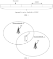
FIG. 1 shows a schematic diagram of carrier aggregation provided by an exemplary embodiment of the present application; -
FIG. 2 shows a block diagram of a communication system provided by an exemplary embodiment of the present application; -
FIG. 3 shows a flowchart of a method for activating a secondary cell provided by an exemplary embodiment of the present application; -
FIG. 4 shows a block diagram of an apparatus for activating a secondary cell provided by an exemplary embodiment of the present application; -
FIG. 5 shows a block diagram of an apparatus for activating a secondary cell provided by an exemplary embodiment of the present application; -
FIG. 6 shows a block diagram of an apparatus for activating a secondary cell provided by an exemplary embodiment of the present application; -
FIG. 7 shows a block diagram of an apparatus for activating a secondary cell provided by an exemplary embodiment of the present application; -
FIG. 8 shows a schematic structural diagram of a communication device provided by an exemplary embodiment of the present application. - In order to make the objectives, technical solutions and advantages of the present application clearer, the embodiments of the present application will be further described in detail below with reference to the accompanying drawings.
- It is understood that the terms "first", "second" and the like used in the present application may be used herein to describe various concepts, but these concepts are not limited by these terms unless otherwise specified. These terms are only used to distinguish one concept from another.
- First, the terms involved in the embodiments of the present application are briefly introduced:
- By jointly scheduling and using resources on a plurality of component carriers, the NR system supports a relatively large bandwidth. Carrier aggregation can be divided into continuous carrier aggregation and discontinuous carrier aggregation according to whether the aggregated carriers are continuous in the spectrum. Carrier aggregation can be divided into intra-band carrier aggregation and inter-band carrier aggregation according to whether the frequency bands in which the aggregated carriers are located are the same.
- The carriers of carrier aggregation include Primary Cell Component (PCC, primary carrier) and Secondary Cell Component (SCC, secondary carrier). There is only one PCC, and PPC is a carrier corresponding to the primary cell. PCC provides an RRC signaling connection, a Non-Access Stratrum (NAS) function, or a security service, and so on. SCC provides additional radio resources. PCC and SCC are both serving cells. In the NR system, the maximum number of carriers through carrier aggregation is 5, and the maximum bandwidth after aggregation is 100 MHZ (megahertz), and the aggregated carriers all belong to the same base station.
- For example, as shown in
FIG. 1 , one carrier aggregation includes 5 carriers, the bandwidth of each carrier is 20MHz, and the maximum bandwidth after aggregation is 100MHz. - In a specific example, the carriers aggregated through carrier aggregation use the same cell radio network temporary identifier (C-RNTI), and the base station can ensure that the C-RNTI does not collide in the cell where each carrier is located. Since carrier aggregation includes asymmetric carrier aggregation and symmetric carrier aggregation, the aggregated carriers are required to include downlink, but may not include uplink.
- The secondary cell is configured through Radio Resource Control (RRC) signaling, and the initial state of the secondary cell is a deactivated state. In this deactivated state, the secondary cell cannot receive or send data. The secondary cell needs to be activated, and the activated secondary cell can receive and send data.
- 3. Reference signal: the reference signal is TRS or CSI RS. Hereinafter, the reference signal will be described by taking the TRS as an example.
- The TRS occupies symbols at preset positions in each slot, for example, the TRS occupies the 5th symbol and the 9th symbol in one slot.
-
FIG. 2 shows a block diagram of a communication system provided by an exemplary embodiment of the present application. The communication system may include: anaccess network 12 and a terminal 13. - The
access network 12 includesseveral network devices 120. Thenetwork device 120 may be an apparatus that provides a radio communication function for the terminal. Thenetwork device 120 may be various forms of base stations (e.g., a macro base station, a micro base station, a relay station) or access points, and the like. In systems using different radio access technologies, the names of devices with base station functions may be different. For example, in the LTE system, they are called eNodeB or eNB; in the 5G NR-U system, they are called gNodeB or gNB. As communications technology evolves, the term "base station" may change. For the convenience of the embodiments of the present application, the above-mentioned apparatuses for providing the terminal 13 with a radio communication function are collectively referred to as an access network device. - The terminal 13 may include various handheld devices, vehicle-mounted devices, wearable devices, computing devices with radio communication functions or other processing devices connected to the wireless modem, as well as various forms of user equipment, Mobile Stations (MS), terminal (terminal device) and so on. For the convenience of description, the devices mentioned above are collectively referred to as a terminal. The
access network device 120 and the terminal 13 communicate with each other through a certain air interface technology, such as a Uu interface. - The technical solutions of the embodiments of the present application may be applied to various communication systems, for example: a Global System of Mobile communication (GSM) system, a Code Division Multiple Access (CDMA) system, a Wideband Code Division Multiple Access (WCDMA) system, General Packet Radio Service (GPRS), a Long Term Evolution (LTE) system, an LTE Frequency Division Duplex (FDD) system, an LTE Time Division Duplex (TDD) system, an Advanced Long Term Evolution (LTE-A) system, a New Radio (NR) system, an NR system evolution system, an LTE-based access to unlicensed spectrum (LTE-U) system, an NR-U system, a Universal Mobile Telecommunication System (UMTS), a Worldwide Interoperability for Microwave Access (WiMAX) communication system, Wireless Local Area Networks (WLAN), Wireless Fidelity (WiFi), a next-generation communication system or other communication systems, etc.
- Generally speaking, traditional communication systems support a limited number of connections, which are easy to be implemented. However, with the development of communication technology, the mobile communication system will not only support traditional communication, but also support, for example, Device to Device (D2D) communication, Machine to Machine (M2M) communication, Machine Type Communication (MTC), Vehicle to Vehicle (V2V) communication and Vehicle to Everything (V2X) system, etc. The embodiments of the present application may also be applied to these communication systems.
-
FIG. 3 shows a flowchart of a method for activating a secondary cell provided by an exemplary embodiment of the present application, which is applied to the terminal and the network device shown inFIG. 2 , and the method includes at least part of the following contents. - In 310, the network device sends a reference signal activation signaling.
- In 320, the terminal receives the reference signal activation signaling.
- The reference signal activation signaling is used for activating a reference signal. In addition, the reference signal activation signaling may also be other types of signaling, and these signalings also have the function of activating the reference signal, which is not limited in the embodiments of the present application. The reference signal is used for activation of the secondary cell.
- The embodiments of the present application are applied in a carrier aggregation scenario. If a plurality of carriers are aggregated through the carrier aggregation technology, the primary cell corresponds to one of the aggregated plurality of carriers, and the secondary cell corresponds to another of the aggregated plurality of carriers. When the carrier corresponding to the secondary cell needs to be used to transmit data, the network device sends the reference signal activation signaling to the terminal, and the reference signal can be activated through the reference signal activation signaling. The network device sends the reference signal, and then the terminal activates the secondary cell based on the reference signal sent by the network device, and transmits data by using the carrier corresponding to the secondary cell.
- In some embodiments, the reference signal activation signaling is any one of Medium Access Control (MAC) Control Element (CE) or Downlink Control Information (DCI).
- If the reference signal activation signaling is MAC CE, the network device sends the MAC CE, the terminal receives the MAC CE, determines the secondary cell to be activated subsequently, and then activates the secondary cell based on the received reference signal.
- If the reference signal activation signaling is DCI, the network device sends the DCI, the terminal receives the DCI, determines the secondary cell to be activated subsequently, and then activates the secondary cell based on the received reference signal.
- The reference signal in the embodiments of the present application is a Tracking Reference Signal (TRS).
- In 330, the network device sends a reference signal based on the reference signal activation signaling.
- In 340, the terminal receives the reference signal based on the reference signal activation signaling, and activates the secondary cell.
- In the embodiments of the present application, after receiving the reference signal activation signaling, the terminal determines a time domain position of the reference signal based on the reference signal activation signaling, and then receives the reference signal based on the time domain position of the reference signal to activate the secondary cell.
- First, the starting time domain position of the reference signal will be described.
- In some embodiments, the terminal determines the starting time domain position of the reference signal based on the time domain position at which the reference signal activation signaling is sent, and starts receiving the reference signal at the starting time domain position of the reference signal.
- The reference signal activation signaling includes two cases of MAC CE or DCI, then determining the starting time domain position of the reference signal also includes the following two cases:
- (1) If the reference signal activation signaling is an MAC CE, the starting time domain position of the reference signal is a time domain position corresponding to a first preset duration after the moment when the MAC CE is sent.
- If the terminal receives the MAC CE after the network device sends the MAC CE to the terminal, and the time domain position for sending the MAC CE is determined, and then the starting time domain position of the reference signal is determined based on the time domain position of the MAC CE, the network device sends the reference signal at the starting time domain position of the reference signal, and the terminal receives the reference signal at the starting time domain position.
- The terminal receives the MAC CE and needs to process the MAC CE to obtain the information included in the MAC CE. The process of the MAC CE by the terminal requires the first preset duration. Therefore, the reference signal is received at a time domain position corresponding to the first preset duration after the time of sending the MAC CE.
- The first preset duration is set by the network device, or set by the operator, or set by other methods. For example, the first preset duration is 40 milliseconds, 50 milliseconds, or other values.
- In a possible implementation manner, the first preset duration is represented by a time unit, for example, the first preset duration is T time units. T is an integer. The time unit is a symbol or the time unit is a slot.
- Or, the starting time domain position of the reference signal is a time domain position corresponding to a second preset duration after the moment when a confirmation message of the MAC CE is sent.
- The confirmation message is a HARQ-ACK message. The terminal receives the MAC CE, parses the MAC CE, and the terminal also needs to return the confirmation message of the MAC CE to the network device, so it is determined that the time domain position corresponding to the second preset duration after the terminal sends the confirmation message of the MAC CE is the starting time domain position of the reference signal.
- The second preset duration is set by the network device, or set by the operator, or set by other methods. For example, the second preset duration is 20 milliseconds, 30 milliseconds, or other values.
- (2) If the reference signal activation signaling is DCI, the starting time domain position of the reference signal is a time domain position corresponding to a third preset duration after the moment when the DCI is sent.
- If the terminal determines the starting time domain position of the reference signal based on the time domain position of the DCI after the network device sends the DCI to the terminal, the network device starts sending the reference signal at the starting time domain position, and the terminal starts receiving the reference signal at the starting time domain position.
- After the terminal receives the DCI, it needs to process the DCI to obtain the information included in the DCI. The processing of the DCI by the terminal requires a certain period of time. Therefore, the terminal may receive the reference signal at the time domain position corresponding to the third preset duration after the moment of sending the DCI.
- The third preset duration is determined by the following formula:

where Tproc is the third preset duration, k and Tc are constants, µ=0, 1, 2, 3, N 1 is the processing time of PDSCH, and N 1 is set by the network device, or set by the operator, or set in other ways. For example, k is 64 and Tc is 1/1966080000. In some embodiments, if the subcarrier spacing is 15KHz (kilohertz), then µ is 0, if the subcarrier spacing is 30KHz, then µ is 1, if the subcarrier spacing is 60KHz, then µ is 2, if the subcarrier spacing is 120KHz, then µ is 3. - In a possible implementation manner, the third preset duration is represented by a time unit, for example, the third preset duration is N time units. N is an integer.
- In addition, if the frequency range to which the secondary cell belongs is FR2 (referring to a frequency range, for example, 24250MHz-52600MHz), an interval between the time domain position of the DCI and the starting time domain position of the reference signal is not less than the third preset duration.
- In the embodiments of the present application, the DCI is used as the reference signal activation signaling, and then the starting time domain position of the reference signal can be determined based on the time domain position where the DCI is sent. Since the terminal can complete the processing of the DCI, there is no need to improve the processing speed of the terminal, which reduces the complexity of the terminal and improves the processing rate of the reference signal.
- In other embodiments, on the basis of determining the starting time domain position of the reference signal according to the reference signal activation signaling, it is also necessary to ensure that the starting time domain position of the reference signal overlaps with the time domain position of the SSB of the activated carrier.
- In the embodiments of the present application, by aggregating a plurality of carriers through the carrier aggregation technology, the network device can activate different carriers and send or receive different information on different carriers. If the starting frequency domain position of the reference signal overlaps with the time domain position of the Synchronization Signal Block (SSB) of the activated carrier, the terminal can detect the reference signal and the SSB at the overlapping time domain position, and can consider a plurality of carriers at the same time, which improves the efficiency of receiving information by the terminal.
- For example, the starting time domain position of the reference signal is in the same slot as the SSB, and the symbol where the reference signal is located is a subset or a universe set of symbols where the SSB is located.
- In other embodiments, the starting time domain position of the reference signal is determined according to the state of the carrier corresponding to the secondary cell.
- In the embodiments of the present application, since the state of the carrier corresponding to the secondary cell includes a plurality of states, the manners of determining the starting time domain position of the reference signal are different in different states.
- The state of the carrier corresponding to the secondary cell is determined according to at least one of a measurement cycle of the secondary cell, a frequency range to which the secondary cell belongs, or whether the secondary cell is known.
- The terminal determines the state of the carrier corresponding to the secondary cell. For example, if the secondary cell is unknown, it determines that the state of the carrier corresponding to the secondary cell is state 1, and if the frequency range to which the secondary cell belongs is FR1 (referring to a frequency range, for example, 450MHz-6000MHz), then it is determined that the state of the carrier corresponding to the secondary cell is state 2, or other states can also be determined.
- Exemplarily, the embodiments of the present application include 9 types of state of carrier. The 9 types of states of carrier are shown in Table 1:
Table 1 Number of state State of carrier 1 If the secondary cell is known and belongs to FR1, and the measurement cycle of the secondary cell is equal to or smaller than 160ms 2 If the secondary cell is known and belongs to FR1, and the measurement cycle of the secondary cell is larger than 160ms 3 If the secondary cell is unknown and belongs to FR1, provided that the side condition conditions/Iot≥- 2dB (ratio) is fulfilled 4 If the activated secondary cell belongs to FR2 and there is at least one active serving cell on the FR2 band, and - SMTC for the target SCell is provided to the terminal, and - The SSBs in the serving cell(s) and the SSBs in the SCell fulfill the condition defined in Section 3.6.3, - The parameter ssb-PositionsInBurst is the same for the serving cell(s) and SCell 5 If the activated SCell belongs to FR2 and there is at least one active serving cell on the FR2 band, if the terminal is not provided with any SMTC for the target SCell - The Reference Symbol (RS) of the activated SCell is Quasi Co-Location (QCL)-TypeD with RS(s) of one active serving cell on that FR2 frequency band 6 If the activated SCell belongs to FR2, and there is no active serving cell on the FR2 band provided that the primary cell (PCell) or the primary secondary cell (PSCell) is in FR1 or in FR2; if the target secondary cell (SCell) is known to the terminal and semi-persistent Channel State Information (CSI)-RS is used for CSI reporting. 7 If the activated SCell belongs to FR2, and if there is no active serving cell on the FR2 band provided that PCell or PSCell is in FR1 or in FR2: If the target SCell is known to the terminal and semi-persistent CSI-RS is used for CSI reporting, if the target SCell is known to the terminal and periodic CSI-RS is used for CSI reporting. 8 If the PCell/PSCell and the target SCell are in a band pair with independent beam management, and the target SCell is unknown to the terminal, and the semi-persistent CSI-RS is used for CSI reporting, provided that the side condition Ês/Iot≥- 2dB is fulfilled. 9 If the PCell/PSCell and the target SCell are in a band pair with independent beam management, and the target SCell is unknown to the terminal, and periodic CSI-RS is used for CSI reporting, provided that the side condition Ês/Iot≥- 2db is fulfilled. - On the basis of the 9 states based on Table 1, if it is determined that the state of the secondary cell is any one of state 2, state 3, state 6, state 7, state 8 or state 9, the determined starting time domain position of the reference signal is not only related to the time domain position of the reference signal activation signaling, but also needs to be guaranteed to overlap with the time domain position of the SSB.
- If it is determined that the state of the secondary cell is either state 1 or state 4, the determined starting time domain position of the reference signal is related to the time domain position of the reference signal activation signaling.
- If it is determined that the state of the secondary cell is state 5, it is not necessary to determine the starting time domain position of the reference signal.
- The first point that needs to be explained is that the terminal and the network device in the embodiments of the present application both determine the starting time domain position of the reference signal by using the above manners.
- The second point that needs to be explained is that the embodiments of the present application are only described by taking the terminal determining the starting time domain position of the reference signal according to the time domain position of the reference signal activation signaling as an example. In another embodiment, the starting time domain position of the reference signal can also be indicated by the network device, without the need for the terminal to determine based on the time domain position of the reference signal activation signaling.
- In the above-mentioned embodiment, the description has been given on how to determine the starting time domain position of the reference signal. Next, how to determine the time domain length of the reference signal will be described.
- In the embodiments of the present application, the time domain length of the reference signal can be determined in the following three ways:
- (1) The time domain length of the reference signal is determined according to the state of the carrier.
- (2) The time domain length of the reference signal is indicated by a reference signal configuration signaling sent by the network device.
- (3) The time domain length of the reference signal is a preset length.
- The time domain length of the reference signal is used to represent the number of time domain positions corresponding to the reference signal. For example, the reference signal occupies 4 time domain positions, or the reference signal occupies 6 time domain positions, or the reference signal occupies other number of time domain positions.
- The time domain length of the reference signal is represented by the number of time domain units, or the time domain length of the reference signal is represented by the number of times of repeated transmission of the reference signal.
- For example, if the time domain length of the reference signal is represented by symbols, the number of time domain positions occupied by the reference signal is the same as the number of the symbols. If the time domain length of the reference signal is represented by slots, the number of time domain positions occupied by the reference signal is twice the number of slots. If the time domain length of the reference signal is represented by the number of repeated transmissions of the reference signal, the number of time domain positions occupied by the reference signal is four times the number of repeated transmissions.
- It should be noted that the embodiments of the present application only take the number of repeated transmissions or the number of time domain units to represent the time domain length of the reference signal as an example for description, and the present application is not limited to the above-mentioned methods, and other methods can also be used to represent the time domain length of the reference signal.
- When the time domain length of the reference signal is determined by way (1), for the time-frequency synchronization function, a plurality of time domain positions of the reference signal are required, and time-frequency synchronization is realized according to a difference between the plurality of time domain positions. Or, for the frequency gain control function, if the reference signal is one symbol, the frequency gain control can be completed, and if the reference signal is a plurality of symbols, the frequency gain control can also be completed. Then, in the above way, the time domain length of the reference signal can be determined according to the states of the carriers of different secondary cells.
- Next, on the basis of the 9 states shown in Table 1 above, the time domain length of the reference signal shown in Table 2 can be determined:
Table 2 Number of state State of carrier Number of symbols occupied by reference signal Number of slots for configuring reference signal Usage 1 If the secondary cell is known and belongs to FR1, and the measurement cycle of the secondary cell is equal to or smaller than 160ms 4 2 Time-frequency synchronization 2 If the secondary cell is known and belongs to FR1, and the measurement cycle of the secondary cell is larger than 160ms 6 3 AGC setting and time-frequency synchronization 3 If the secondary cell is unknown and belongs to FR1, provided that the side condition conditions/Iot ≥ -2dB is fulfilled 8 4 AGC setting and time-frequency synchronization 4 If the activated secondary cell belongs to FR2 and there is at least one active serving cell on the FR2 band, and 4 2 Time-frequency synchronization - SMTC for the target SCell is provided to the terminal, and - The SSBs in the serving cell(s) and the SSBs in the SCell fulfill the condition defined in clause 3.6.3, - The parameter ssb-PositionsInBurst is same for the serving cell(s) and the SCell 5 If the activated SCell belongs to FR2 and there is at least one active serving cell on the FR2 band, if the terminal is not provided with any SMTC for the target SCell 0 0 None - the RS(s) of the activated SCell is(are) QCL-TypeD with RS(s) of one active serving cell on that FR2 band 6 If the activated SCell belongs to FR2, and there is no active serving cell on the FR2 band provided that PCell or PSCell is in FR1 or in FR2: 6 3 AGC setting and time-frequency synchronization If the target SCell is known to the terminal and semi-persistent CSI-RS is used for CSI reporting 7 If the activated SCell belongs to FR2, and if there is no active serving cell on the FR2 band provided that PCell or PSCell is in FR1 or in FR2: 6 3 AGC setting and time-frequency synchronization If the target SCell is known to the terminal and semi-persistent CSI-RS is used for CSI reporting. If the target SCell is known to the terminal and periodic CSI-RS is used for CSI reporting 8 If the PCell/PSCell and the target SCell are in a band pair with independent beam management, and the target SCell is unknown to the terminal, and semi-persistent CSI-RS is used for CSI reporting, provided that the side condition Ês/Iot≥- 2dB is fulfilled 48 24 AGC setting and time-frequency synchronization of a plurality of beams 9 If the PCell/PSCell and the target SCell are in a band pair with independent beam management, and the target SCell is unknown to the terminal, and periodic CSI-RS is used for CSI reporting, provided that the side condition Ês/Iot≥-2dB is fulfilled 48 24 AGC setting and time-frequency synchronization of a plurality of beams - When the time domain length of the reference signal is determined by way (2), the terminal does not need to determine the time domain length of the reference signal based on the state of the carrier of the secondary cell, the network device can send the reference signal configuration signaling to the terminal, and the terminal receives the reference signal configuration signaling, and determines the time domain length of the reference signal based on the reference signal configuration signaling.
- When the time domain length of the reference signal is determined by way (3), the time domain length of the reference signal determined by the terminal is a preset length.
- The preset length is set by the network device, or set by the operator, or set by other ways. The above preset length is just an example, and may be other values in practical applications.
- In the embodiments of the present application, regardless of the state of the carrier of the secondary cell, the time domain length of the reference signal is determined as the preset length, which reduces the operation of the terminal for determining the time domain length of the reference signal, and improves the efficiency of determining the time domain length of the reference signal.
- Next, how to determine the time domain position of the reference signal will be described.
- The time domain position of the reference signal is determined according to the state of the carrier corresponding to the secondary cell. The state of the carrier corresponding to the secondary cell is determined according to at least one of a measurement cycle of the secondary cell, a frequency range to which the secondary cell belongs, or whether the secondary cell is known.
- If the state of the carrier corresponding to the secondary cell is that the time domain synchronization is completed according to the reference signal, it is determined that there is an interval between the time domain positions of the reference signal, or the reference signal includes a reference signal used for frequency gain control setting and a reference signal used for time-frequency synchronization, if the state of the carrier is to complete time domain synchronization and frequency gain control setting according to the reference signal, the reference signal used for frequency gain control setting is adjacent to the reference signal used for time-frequency synchronization.
- In addition, since the state of the carrier is different, the dependence of the terminal on the reference signal is also different. For different carrier states, the number of time domain positions of the reference signal and the interval of the time domain positions are also different.
- For example, for state 1, the terminal completes time-frequency synchronization according to the reference signal, and there is an interval between the time domain positions of the reference signal.
- For state 2, the terminal completes time domain synchronization and frequency gain control according to the reference signal. In order to reduce the delay and avoid repeated frequency gain control settings, the reference signal used for frequency gain control is adjacent to the reference signal used for time-frequency synchronization, and there is an interval between the time domain positions of the reference signal used for time-frequency synchronization.
- For state 3, the terminal completes time domain synchronization and frequency gain control according to the reference signal, and the frequency gain control needs to be set multiple times, so a plurality of reference signals are required. The plurality of reference signals used for frequency gain control are adjacent, and there is an interval between the plurality of reference signals used for time-frequency synchronization.
- For state 4, the terminal completes time-frequency synchronization according to the reference signal, and there is an interval between the time domain positions of the reference signal.
- For state 5, the terminal does not need to receive the reference signal.
- For state 6, the terminal completes time domain synchronization and frequency gain control according to the reference signal. In order to reduce the delay and avoid repeated frequency gain control settings, the reference signal used for frequency gain control is adjacent to the reference signal used for time-frequency synchronization, and there is an interval between the time domain positions of the reference signal used for time-frequency synchronization.
- For state 7, the terminal completes time domain synchronization and frequency gain control according to the reference signal. In order to reduce the delay and avoid repeated frequency gain control settings, the reference signal used for frequency gain control is adjacent to the reference signal used for time-frequency synchronization, and there is an interval between the time domain positions of the reference signal used for time-frequency synchronization.
- For state 8, for the same beam (with QCL Type D relationship between signals), it is the same as state 3. A plurality of beams are repeatedly mapped on different symbols. There is a certain interval between different beams to meet the time for beam switching.
- For state 9, for the same beam (with QCL Type D relationship between signals), it is the same as state 3. A plurality of beams are repeatedly mapped on different symbols. There is a certain interval between different beams to meet the time for beam switching.
- For example, taking the states in Table 1 and the reference signal as TRS as an example, Table 3 shows the time domain position of the reference signal corresponding to each state, and the value of x is 5:
Table 3 Number of state First column of TRS Second column ofTRS Third column of TRS Fourth column of TRS 1 X X+5 0 0 2 X X+1 X+5 0 3 X X+1 X+2 X+6 4 X X+5 0 0 5 0 0 0 0 6 X X+1 X+5 0 7 X X+1 X+5 0 8 X X+1 X+2 X+6 9 X X+1 X+2 X+6 - In other embodiments, the time domain position of the reference signal is a slot occupied by the reference signal and/or a preset position in the slot.
- In the embodiments of the present application, if the carriers corresponding to the secondary cell all satisfy the above conditions, each time domain position of the reference signal is determined by using the existing format of the time domain position of the reference signal. For example, as shown in Table 4, the time domain position of the reference signal occupies the 5th symbol and the 9th symbol in the slot, and the value of x is 5.
Table 4 Number of state First column of TRS Second column of TRS Third column of TRS Fourth column of TRS Fifth column of TRS Sixth column of TRS Seventh column of TRS Eighth column of TRS 1 X X+4 X+14 X+18 0 0 0 0 2 X X+4 X+14 X+18 X+28 X+32 0 0 3 X X+4 X+14 X+18 X+28 X+32 X+42 X+46 4 X X+4 X+14 X+18 0 0 0 0 5 0 0 0 0 0 0 0 0 6 X X+4 X+14 X+18 X+28 X+32 0 0 7 X X+4 X+14 X+18 X+28 X+32 0 0 8 X X+4 X+14 X+18 X+28 X+32 Perform 8 cycles 9 X X+4 X+14 X+18 X+28 X+32 Perform 8 cycles - If the starting time domain position of the reference signal does not overlap with the time domain position of the SSB of the activated carrier, an offset is performed on the starting time domain position of the reference signal, and the time domain position of the reference signal after offset overlaps with the time domain position of the SSB.
- In other embodiments, if the reference signal has a quasi-co-located relationship with the SSB or CSI RS, the measurement related to the SSB or CSI can be performed according to the reference signal.
- The quasi-co-location relationship includes four types, namely, a quasi-co-location relationship of type A, a quasi-co-location relationship of type B, a quasi-co-location relationship of type C, and a quasi-co-location relationship of type D.
- The quasi-co-location relationship of type A has the characteristics of Doppler frequency shift, Doppler spread, average delay and delay spread, and the quasi-co-location relationship of type B has the characteristics of Doppler frequency shift and Doppler spread, the quasi-co-location relationship of type C has the characteristics of Doppler frequency shift and average delay, and the quasi-co-location relationship of type D has the characteristics of spatial reception parameter.
- (1) If the reference signal and the SSB have a quasi-co-location relationship, the SSB is detected according to the reference signal.
The reference signal and the SSB have a quasi-co-location relationship of type C, or a quasi-co-location relationship of type C and type D. - (2) If the reference signal and the channel state indication reference signal (CSI RS) used for the channel state indication (CSI) measurement have a quasi-co-located relationship, CSI measurement is performed according to the reference signal.
- The reference signal and the CSI RS have a quasi-co-location relationship of type A, or a quasi-co-location relationship of type B, or a quasi-co-location relationship of type A and type D.
- It should be noted that, the embodiments of the present application only take the reference signal and SSB or CSI measurement having a quasi-co-location relationship as an example for description. In another embodiment, the reference signal does not have a quasi-co-location relationship with the SSB or CSI, and the reference signal received by the terminal is only used for frequency gain control or time-frequency synchronization.
- With the method provided by the embodiments of the present application, the terminal can receive the reference signal based on the reference signal activation signaling, and then activate the secondary cell, without waiting for the first SSB to activate the secondary cell, reducing the time for waiting to receive the first SSB, and thus reducing the time delay of activating the secondary cell, and improving the accuracy of activating the secondary cell.
- In addition, the terminal activates the secondary cell according to the received reference signal without parsing the SSB, which reduces the processing resource consumed in the parsing process, thereby saving the resource of the terminal.
- In addition, the starting resource position of the reference signal, the time domain length of the reference signal and the time domain position of the reference signal are respectively defined, which ensures that the reference signal can activate the secondary cell in any scenario and improves the efficiency of activating the secondary cell.
- Moreover, the time domain length of the reference signal can be determined in various ways, which improves the flexibility of determining the reference signal, and further improves the flexibility of activating the secondary cell.
-
FIG. 4 shows a block diagram of an apparatus for activating a secondary cell provided by an exemplary embodiment of the present application. The apparatus is applied to a terminal, and the apparatus includes: - a
receiving module 401, configured to receive a reference signal activation signaling, where the reference signal activation signaling is used for activating a reference signal, and the reference signal is used for activation of the secondary cell; - a
receiving module 401, configured to receive the reference signal based on the reference signal activation signaling; - an
activation module 402, configured to activate the secondary cell. - With the apparatus provided by the embodiment of the present application, the terminal can receive the reference signal based on the reference signal activation signaling, and then activate the secondary cell, without waiting for the first SSB to activate the secondary cell, reducing the time for waiting to receive the first SSB, and thus reducing the time delay of activating the secondary cell, and improving the accuracy of activating the secondary cell.
- In some embodiments, the reference signal activation signaling is any one of MAC CE or DCI.
- In some embodiments, the reference signal activation signaling is MAC CE, and the starting time domain position of the reference signal is a time domain position corresponding to a first preset duration after the moment when the MAC CE is sent; or, the starting time domain position of the reference signal is a time domain position corresponding to a second preset duration after the moment when a confirmation message of the MAC CE is sent.
- In some embodiments, the reference signal activation signaling is DCI, and the starting time domain position of the reference signal is a time domain position corresponding to a third preset duration after the moment when the DCI is sent.
- In some embodiments, the third preset duration is determined by the following formula:

where Tproc is the third preset duration, k and Tc are constants, µ=0, 1, 2, 3, and N1 is the processing time of PDSCH. - In some embodiments, the starting time domain position of the reference signal overlaps with the time domain position of the SSB of the activated carrier.
- In some embodiments, the starting time domain position of the reference signal is determined according to the state of the carrier corresponding to the secondary cell.
- In some embodiments, the time domain length of the reference signal is determined according to the state of the carrier corresponding to the secondary cell, or the time domain length of the reference signal is indicated by a reference signal configuration signaling sent by the network device, or the time domain length of the reference signal is a preset length.
- In some embodiments, the time domain length of the reference signal is represented by the number of time domain units, or the time domain length of the reference signal is represented by the number of repeated transmissions of the reference signal.
- In some embodiments, the time domain unit is a symbol, or the time domain unit is a slot.
- In some embodiments, the time domain position of the reference signal is determined according to the state of the carrier corresponding to the secondary cell.
- In some embodiments, the time domain position of the reference signal is a slot occupied by the reference signal and/or a preset position in the slot.
- In some embodiments, referring to
FIG. 5 , the apparatus further includes:
an offsetmodule 403, configured to perform an offset on the starting time domain position of the reference signal if the starting time domain position of the reference signal does not overlap with the time domain position of the SSB of the activated carrier, where the time domain position of the reference signal after offset overlaps with the time domain position of the SSB of the activated carrier. - In some embodiments, the state of the carrier corresponding to the secondary cell is determined according to at least one of a measurement cycle of the secondary cell, a frequency range to which the secondary cell belongs, or whether the secondary cell is known.
- In some embodiments, the reference signal is a tracking reference signal (TRS).
- Regarding the apparatuses in the above-mentioned embodiments, the specific manners in which each module performs operations have been described in detail in the embodiments of the method, which will not be described in detail here.
- The above-mentioned
activation module 402 or offsetmodule 403 may also be a processing module, and may be a processor in specific implementation. Theabove receiving module 401 may be a receiver or a transceiver during specific implementation. -
FIG. 6 shows a block diagram of an apparatus for activating a secondary cell provided by an exemplary embodiment of the present application. The apparatus is applied to a network device, and the apparatus includes: - a sending
module 601, configured to send a reference signal activation signaling, where the reference signal activation signaling is used for activating a reference signal, and the reference signal is used for activation of the secondary cell; - a sending
module 601, configured to send the reference signal based on the reference signal activation signaling. - With the apparatuses provided by the embodiments of the present application, the terminal can receive the reference signal based on the reference signal activation signaling, and then activate the secondary cell, without waiting for the first SSB to activate the secondary cell, reducing the time for waiting to receive the first SSB, thereby reducing the time delay of activating the secondary cell, and improving the accuracy of activating the secondary cell.
- In some embodiments, the reference signal activation signaling is any one of MAC CE or DCI.
- In some embodiments, the reference signal activation signaling is MAC CE, and the starting time domain position of the reference signal is the time domain position corresponding to the first preset duration after the time when the MAC CE is sent; or, the starting time domain position of the reference signal is the time domain position corresponding to the second preset duration after the moment when the confirmation message of the MAC CE is sent.
- In some embodiments, the reference signal activation signaling is DCI, and the starting time domain position is a time domain position corresponding to a third preset duration after the moment when the DCI is sent.
- In some embodiments, the third preset duration is determined by the following formula:

wherein Tproc is the third preset duration, k and Tc are constants, µ=0, 1, 2, 3, and N1 is a processing time of PDSCH. - In some embodiments, the starting time domain position of the reference signal overlaps with the time domain position of the SSB of the activated carrier.
- In some embodiments, the starting time domain position of the reference signal is determined according to the state of the carrier corresponding to the secondary cell.
- In some embodiments, the time domain length of the reference signal is determined according to the state of the carrier corresponding to the secondary cell, or the time domain length of the reference signal is indicated by the reference signal configuration signaling sent by the network device, or the time domain length of the reference signal is the preset length.
- In some embodiments, the time domain length of the reference signal is represented by the number of time domain units, or the time domain length of the reference signal is represented by the number of repeated transmissions of the reference signal.
- In some embodiments, the time domain units are symbols, or alternatively, the time domain units are slots.
- In some embodiments, the time domain position of the reference signal is determined according to the state of the carrier corresponding to the secondary cell.
- In some embodiments, the time domain position of the reference signal is a slot occupied by the reference signal and/or a preset position in the slot.
- In some embodiments, referring to
FIG. 7 , the apparatus further includes:
an offsetmodule 602, configured to perform an offset on the starting time domain position of the reference signal if the starting time domain position of the reference signal does not overlap with the time domain position of the SSB of the activated carrier, where the time domain position of the reference signal after offset overlaps with the time domain position of the SSB of the activated carrier. - In some embodiments, the state of the carrier corresponding to the secondary cell is determined according to at least one of a measurement cycle of the secondary cell, a frequency range to which the secondary cell belongs, or whether the secondary cell is known.
- In some embodiments, the reference signal is a tracking reference signal (TRS).
- Regarding the apparatus in the above-mentioned embodiments, the specific manner in which each module performs operations has been described in detail in the embodiments of the method, which will not be described in detail here.
- The above offset
module 602 may also be a processing module, and may be a processor in specific implementation. The above-mentionedsending module 601 may be a transmitter or a transceiver during specific implementation. -
FIG. 8 shows a schematic structural diagram of a communication device provided by an exemplary embodiment of the present application. The communication device includes: aprocessor 801, areceiver 802, atransmitter 803, amemory 804, and abus 805. - The
processor 801 includes one or more processing cores, and theprocessor 801 executes various functional applications and information processing by running software programs and modules. - The
receiver 802 and thetransmitter 803 may be implemented as one communication component. - The
memory 804 is connected to theprocessor 801 through thebus 805. - The
memory 804 may be configured to store at least one program code, and theprocessor 801 is configured to execute the at least one program code, so that the communication device implements each step in the above method embodiments. - Furthermore, the communication device may be a terminal or a base station. The
memory 804 may be implemented by any type or combination of volatile or non-volatile storage devices including, but not limited to: a magnetic disk or an optical disk, an electrically erasable programmable read-only Memory (EEPROM), an Erasable Programmable Read Only Memory (EPROM), a Static Random Access Memory (SRAM), a Read Only Memory (ROM), a magnetic memory, a flash memory, a Programmable Read Only Memory (PROM). - In an exemplary embodiment, a computer-readable storage medium is also provided, in which executable program code is stored, and the executable program code is loaded and executed by the processor to implement the method for activating a secondary cell performed by the communication device provided by the above individual method embodiments.
- Those of ordinary skill in the art can understand that all or part of the steps of implementing the above embodiments can be completed by hardware, or can be completed by instructing relevant hardware through a program, and the program can be stored in a computer-readable storage medium. The storage medium mentioned may be a read-only memory, a magnetic disk or an optical disk, etc.
- The above descriptions are only optional embodiments of the present application, and are not intended to limit the present application. Any modifications, equivalent replacements, improvements, etc. made within the spirit and principles of the present application shall be included in the protection scope of the present application.
Claims (63)
- A method for activating a secondary cell, applied to a terminal, the method comprising:receiving a reference signal activation signaling, wherein the reference signal activation signaling is used for activating a reference signal, and the reference signal is used for activation of the secondary cell; andreceiving the reference signal based on the reference signal activation signaling, and activating the secondary cell.
- The method of claim 1, wherein:
the reference signal activation signaling is any one of an MAC CE or a DCI. - The method of claim 1, wherein:
the reference signal activation signaling is an MAC CE, and a starting time domain position of the reference signal is a time domain position corresponding to a first preset duration after a moment when the MAC CE is sent; or, the starting time domain position of the reference signal is a time domain position corresponding to a second preset duration after a moment when a confirmation message of the MAC CE is sent. - The method of claim 1, wherein:
the reference signal activation signaling is a DCI, and a starting time domain position of the reference signal is a time domain position corresponding to a third preset duration after a moment when the DCI is sent. - The method of claim 4, wherein the third preset duration is determined by the following formula:

- The method of claim 1, wherein a starting time domain position of the reference signal overlaps with a time domain position of an SSB of an activated carrier.
- The method of claim 1, wherein a starting time domain position of the reference signal is determined according to a state of a carrier corresponding to the secondary cell.
- The method of claim 1, wherein a time domain length of the reference signal is determined according to a state of a carrier corresponding to the secondary cell, or the time domain length of the reference signal is indicated by a reference signal configuration signaling sent by a network device, or the time domain length of the reference signal is a preset length.
- The method of claim 8, wherein the time domain length of the reference signal is represented by a number of time domain units, or the time domain length of the reference signal is represented by a number of repeated transmissions of the reference signal.
- The method of claim 9, wherein the time domain unit is a symbol, or the time domain unit is a slot.
- The method of claim 1, wherein a time domain position of the reference signal is determined according to a state of a carrier corresponding to the secondary cell.
- The method of claim 1, wherein a time domain position of the reference signal is a slot occupied by the reference signal and/or a preset position in the slot.
- The method of claim 1, wherein the method further comprises:
in response to that the starting time domain position of the reference signal does not overlap with a time domain position of an SSB of an activated carrier, performing an offset on the starting time domain position of the reference signal, wherein the time domain position of the reference signal after the offset overlaps with the time domain position of the SSB of the activated carrier. - The method of any one of claims 7-11, wherein the state of the carrier corresponding to the secondary cell is determined according to at least one of a measurement cycle of the secondary cell, a frequency range to which the secondary cell belongs, or whether the secondary cell is known.
- The method of any one of claims 1-14, wherein the reference signal is a tracking reference signal (TRS).
- A method for activating a secondary cell, applied to a network device, the method comprising:sending a reference signal activation signaling, wherein the reference signal activation signaling is used for activating a reference signal, and the reference signal is used for activation of the secondary cell; andsending the reference signal based on the reference signal activation signaling.
- The method of claim 16, wherein:
the reference signal activation signaling is any one of an MAC CE or a DCI. - The method of claim 16, wherein:
the reference signal activation signaling is an MAC CE, and a starting time domain position of the reference signal is a time domain position corresponding to a first preset duration after a moment when the MAC CE is sent; or, the starting time domain position of the reference signal is a time domain position corresponding to a second preset duration after a moment when a confirmation message of the MAC CE is sent. - The method of claim 16, wherein:
the reference signal activation signaling is a DCI, and the starting time domain position is a time domain position corresponding to a third preset duration after a moment when the DCI is sent. - The method of claim 19, wherein the third preset duration is determined by the following formula:

- The method of claim 16, wherein a starting time domain position of the reference signal overlaps with a time domain position of an SSB of an activated carrier.
- The method of claim 16, wherein a starting time domain position of the reference signal is determined according to a state of a carrier corresponding to the secondary cell.
- The method of claim 16, wherein a time domain length of the reference signal is determined according to a state of a carrier corresponding to the secondary cell, or the time domain length of the reference signal is indicated by a reference signal configuration signaling sent by a network device, or the time domain length of the reference signal is a preset length.
- The method of claim 23, wherein the time domain length of the reference signal is represented by a number of time domain units, or the time domain length of the reference signal is represented by a number of repeated transmissions of the reference signal.
- The method of claim 24, wherein the time domain unit is a symbol, or the time domain unit is a slot.
- The method of claim 16, wherein a time domain position of the reference signal is determined according to a state of a carrier corresponding to the secondary cell.
- The method of claim 16, wherein a time domain position of the reference signal is a slot occupied by the reference signal and/or a preset position in the slot.
- The method of claim 16, wherein the method further comprises:
in response to that an starting time domain position of the reference signal does not overlap with a time domain position of an SSB of an activated carrier, performing an offset on the starting time domain position of the reference signal, wherein the time domain position of the reference signal after the offset overlaps with the time domain position of the SSB of the activated carrier. - The method of any one of claims 22-26, wherein the state of the carrier corresponding to the secondary cell is determined according to at least one of a measurement cycle of the secondary cell, a frequency range to which the secondary cell belongs, or whether the secondary cell is known.
- The method of any one of claims 16-29, wherein the reference signal is a tracking reference signal (TRS).
- An apparatus for activating a secondary cell, applied to a terminal, the apparatus comprising:a receiving module, configured to receive a reference signal activation signaling, wherein the reference signal activation signaling is used for activating a reference signal, and the reference signal is used for activation of the secondary cell;the receiving module being configured to receive the reference signal based on the reference signal activation signaling, andan activation module, configured to activate the secondary cell.
- The apparatus of claim 31, wherein:
the reference signal activation signaling is any one of an MAC CE or a DCI. - The apparatus of claim 31, wherein:
the reference signal activation signaling is an MAC CE, and a starting time domain position of the reference signal is a time domain position corresponding to a first preset duration after a moment when the MAC CE is sent; or, the starting time domain position of the reference signal is a time domain position corresponding to a second preset duration after a moment when a confirmation message of the MAC CE is sent. - The apparatus of claim 31, wherein:
the reference signal activation signaling is a DCI, and a starting time domain position of the reference signal is a time domain position corresponding to a third preset duration after a moment when the DCI is sent. - The apparatus of claim 34, wherein the third preset duration is determined by the following formula:

- The apparatus of claim 31, wherein a starting time domain position of the reference signal overlaps with a time domain position of an SSB of an activated carrier.
- The apparatus of claim 31, wherein a starting time domain position of the reference signal is determined according to a state of a carrier corresponding to the secondary cell.
- The apparatus of claim 31, wherein a time domain length of the reference signal is determined according to a state of a carrier corresponding to the secondary cell, or the time domain length of the reference signal is indicated by a reference signal configuration signaling sent by a network device, or the time domain length of the reference signal is a preset length.
- The apparatus of claim 38, wherein the time domain length of the reference signal is represented by a number of time domain units, or the time domain length of the reference signal is represented by a number of repeated transmissions of the reference signal.
- The apparatus of claim 39, wherein the time domain unit is a symbol, or the time domain unit is a slot.
- The apparatus of claim 31, wherein a time domain position of the reference signal is determined according to a state of a carrier corresponding to the secondary cell.
- The apparatus of claim 31, wherein a time domain position of the reference signal is a slot occupied by the reference signal and/or a preset position in the slot.
- The apparatus of claim 31, wherein the apparatus further comprises:
an offset module, configured to, in response to that the starting time domain position of the reference signal does not overlap with a time domain position of an SSB of an activated carrier, perform an offset on the starting time domain position of the reference signal, wherein the time domain position of the reference signal after the offset overlaps with the time domain position of the SSB of the activated carrier. - The apparatus of any one of claims 37-41, wherein the state of the carrier corresponding to the secondary cell is determined according to at least one of a measurement cycle of the secondary cell, a frequency range to which the secondary cell belongs, or whether the secondary cell is known.
- The apparatus of any one of claims 31-44, wherein the reference signal is a tracking reference signal (TRS).
- An apparatus for activating a secondary cell, applied to network device, the apparatus comprising:a sending module, configured to send a reference signal activation signaling, wherein the reference signal activation signaling is used for activating a reference signal, and the reference signal is used for activation of the secondary cell;a sending module, configured to send the reference signal based on the reference signal activation signaling.
- The apparatus of claim 46, wherein:
the reference signal activation signaling is any one of an MAC CE or a DCI. - The apparatus of claim 46, wherein:
the reference signal activation signaling is an MAC CE, and a starting time domain position of the reference signal is a time domain position corresponding to a first preset duration after a moment when the MAC CE is sent; or, the starting time domain position of the reference signal is a time domain position corresponding to a second preset duration after a moment when a confirmation message of the MAC CE is sent. - The apparatus of claim 46, wherein:
the reference signal activation signaling is a DCI, and a starting time domain position is a time domain position corresponding to a third preset duration after a moment when the DCI is sent. - The apparatus of claim 49, wherein the third preset duration is determined by the following formula:

- The apparatus of claim 46, wherein a starting time domain position of the reference signal overlaps with a time domain position of an SSB of an activated carrier.
- The apparatus of claim 46, wherein a starting time domain position of the reference signal is determined according to a state of a carrier corresponding to the secondary cell.
- The apparatus of claim 46, wherein a time domain length of the reference signal is determined according to a state of a carrier corresponding to the secondary cell, or the time domain length of the reference signal is indicated by a reference signal configuration signaling sent by a network device, or the time domain length of the reference signal is a preset length.
- The apparatus of claim 53, wherein the time domain length of the reference signal is represented by a number of time domain units, or the time domain length of the reference signal is represented by a number of repeated transmissions of the reference signal.
- The apparatus of claim 54, wherein the time domain unit is a symbol, or the time domain unit is a slot.
- The apparatus of claim 46, wherein a time domain position of the reference signal is determined according to a state of a carrier corresponding to the secondary cell.
- The apparatus of claim 46, wherein a time domain position of the reference signal is a slot occupied by the reference signal and/or a preset position in the slot.
- The apparatus of claim 46, wherein the apparatus further comprises:
an offset module, configured to, in response to that the starting time domain position of the reference signal does not overlap with a time domain position of an SSB of an activated carrier, perform an offset on the starting time domain position of the reference signal, wherein the time domain position of the reference signal after the offset overlaps with the time domain position of the SSB of the activated carrier. - The apparatus of any one of claims 52-56, wherein the state of the carrier corresponding to the secondary cell is determined according to at least one of a measurement cycle of the secondary cell, a frequency range to which the secondary cell belongs, or whether the secondary cell is known.
- The apparatus of any one of claims 46-59, wherein the reference signal is a tracking reference signal (TRS).
- A terminal, comprising:a processor;a transceiver connected to the processor;a memory for storing executable program codes for the processor;wherein the processor is configured to load and execute the executable program codes to enable the terminal to implement the method for activating a secondary cell of any one of claims 1 to 15.
- A network device, comprising:a processor;a transceiver connected to the processor;a memory for storing executable program codes for the processor;wherein the processor is configured to load and execute the executable program codes to enable the network device to implement the method for activating a secondary cell of any one of claims 16 to 30.
- A computer-readable storage medium, wherein the readable storage medium stores executable program codes, and the executable program codes are loaded and executed by a processor to implement the method for activating a secondary cell of any one of claims 1 to 30.
Applications Claiming Priority (1)
| Application Number | Priority Date | Filing Date | Title |
|---|---|---|---|
| PCT/CN2020/122981 WO2022082657A1 (en) | 2020-10-22 | 2020-10-22 | Secondary cell activation method, apparatus, device, and storage medium |
Publications (3)
| Publication Number | Publication Date |
|---|---|
| EP4236524A1 true EP4236524A1 (en) | 2023-08-30 |
| EP4236524A4 EP4236524A4 (en) | 2023-11-29 |
| EP4236524B1 EP4236524B1 (en) | 2025-06-11 |
Family
ID=81291452
Family Applications (1)
| Application Number | Title | Priority Date | Filing Date |
|---|---|---|---|
| EP20958239.4A Active EP4236524B1 (en) | 2020-10-22 | 2020-10-22 | Secondary cell activation method, apparatus, device, and storage medium |
Country Status (6)
| Country | Link |
|---|---|
| US (1) | US12483367B2 (en) |
| EP (1) | EP4236524B1 (en) |
| JP (1) | JP7612012B2 (en) |
| KR (1) | KR20230092949A (en) |
| CN (2) | CN116097596A (en) |
| WO (1) | WO2022082657A1 (en) |
Families Citing this family (11)
| Publication number | Priority date | Publication date | Assignee | Title |
|---|---|---|---|---|
| WO2022151066A1 (en) * | 2021-01-13 | 2022-07-21 | 华为技术有限公司 | Communication method and apparatus |
| US12375883B2 (en) * | 2021-06-17 | 2025-07-29 | Qualcomm Incorporated | Initial access enhancements for fixed point-to-multipoint millimeter-wave wireless communication networks |
| CN118921677B (en) * | 2023-05-08 | 2025-06-17 | 中国电信股份有限公司北京研究院 | Method, device, terminal and storage medium for activating secondary cell |
| CN119316891A (en) * | 2023-07-12 | 2025-01-14 | 华为技术有限公司 | A secondary cell activation method and communication device |
| US20250056510A1 (en) * | 2023-08-10 | 2025-02-13 | Samsung Electronics Co., Ltd. | Triggering on-demand ssb or sib1 |
| CN120111630A (en) * | 2023-12-06 | 2025-06-06 | 华为技术有限公司 | A method and device for transmitting SSB on a secondary cell |
| WO2025166593A1 (en) * | 2024-02-06 | 2025-08-14 | 富士通株式会社 | Synchronization signal block triggering method and apparatus |
| WO2025174083A1 (en) * | 2024-02-16 | 2025-08-21 | 엘지전자 주식회사 | Method and device for transmitting and receiving signal in wireless communication system |
| KR20250140353A (en) * | 2024-03-18 | 2025-09-25 | 삼성전자주식회사 | Method and apparatus for lower layer signalling based dynamic cell measurement configuration in a wireless communication system |
| WO2026020284A1 (en) * | 2024-07-22 | 2026-01-29 | Apple Inc. | On-demand ssb operation after nes secondary cell activation command |
| CN121771920A (en) * | 2024-09-30 | 2026-03-31 | 大唐移动通信设备有限公司 | Method, apparatus and readable storage medium for determining the transmission time of synchronization signal blocks |
Family Cites Families (31)
| Publication number | Priority date | Publication date | Assignee | Title |
|---|---|---|---|---|
| US9237537B2 (en) * | 2012-01-25 | 2016-01-12 | Ofinno Technologies, Llc | Random access process in a multicarrier base station and wireless device |
| KR102580213B1 (en) * | 2017-06-15 | 2023-09-19 | 삼성전자주식회사 | Method and apparatus for data transmission in wireless communication system |
| CN114025365B (en) * | 2017-08-11 | 2024-04-12 | 华为技术有限公司 | Auxiliary cell activation method, access network equipment, communication device and system |
| US11456830B2 (en) | 2018-01-09 | 2022-09-27 | Qualcomm Incorporated | Aperiod tracking reference signal |
| CN110166192B (en) * | 2018-02-12 | 2020-08-04 | 维沃移动通信有限公司 | Cell processing method, terminal device and network device |
| CN110149178B (en) * | 2018-02-12 | 2020-09-01 | 维沃移动通信有限公司 | Reference signal configuration method, terminal equipment and network side equipment |
| RU2746585C1 (en) * | 2018-02-16 | 2021-04-16 | Телефонактиеболагет Лм Эрикссон (Пабл) | Optimized reconfiguration of rlm parameters and beam control |
| CN110475364B (en) * | 2018-05-09 | 2021-03-26 | 维沃移动通信有限公司 | Method and terminal for receiving non-periodic tracking reference signal |
| KR102645643B1 (en) * | 2018-05-21 | 2024-03-11 | 삼성전자 주식회사 | Method and apparatus for reference signal transmission and reception in wireless communication system |
| CN110839290B (en) * | 2018-08-17 | 2022-04-22 | 成都华为技术有限公司 | Method and communication device for signal transmission |
| CN113302982A (en) | 2018-11-02 | 2021-08-24 | 中兴通讯股份有限公司 | Power saving scheme in wireless communications |
| US11882541B2 (en) * | 2019-01-11 | 2024-01-23 | Apple Inc. | Systems and methods of providing new radio positioning |
| CN113557767B (en) | 2019-02-13 | 2022-09-16 | 荣耀终端有限公司 | Method and apparatus for uplink transmission in power saving mode |
| CN111726213A (en) * | 2019-03-21 | 2020-09-29 | 华硕电脑股份有限公司 | Method and apparatus for beam indication of physical uplink shared channel |
| CN113647170B (en) * | 2019-03-28 | 2025-11-25 | 中兴通讯股份有限公司 | Method and apparatus for rapid service cell activation |
| CN113647045B (en) * | 2019-03-29 | 2024-03-08 | 瑞典爱立信有限公司 | Fast channel state information during activation of a new radio secondary cell |
| CN111757501B (en) * | 2019-03-29 | 2024-11-15 | 北京三星通信技术研究有限公司 | User equipment, base station and data transmission method |
| WO2020264373A1 (en) * | 2019-06-27 | 2020-12-30 | Apple Inc. | Adaptive uplink (ul) timing adjustment for beam switching in fifth-generation new radio (5g nr) |
| KR102947534B1 (en) * | 2019-07-24 | 2026-04-02 | 삼성전자주식회사 | Method and apparatus for channel state information reporting in wireless communication systems |
| US11622239B2 (en) * | 2019-11-01 | 2023-04-04 | Qualcomm Incorporated | TRS for multicast and broadcast |
| JP7451572B2 (en) * | 2020-01-30 | 2024-03-18 | 株式会社Nttドコモ | Terminals, wireless communication methods, base stations and systems |
| CN115462155A (en) * | 2020-03-06 | 2022-12-09 | Idac控股公司 | Dynamic demodulation signal resource allocation |
| US12213099B2 (en) * | 2020-05-15 | 2025-01-28 | Qualcomm Incorporated | Dynamic power sharing and tracking in a communications network |
| WO2022000268A1 (en) * | 2020-06-30 | 2022-01-06 | Qualcomm Incorporated | Indication of doppler pre-compensation in multi-transmission reception point communications |
| EP4183082A4 (en) * | 2020-07-18 | 2024-05-01 | Qualcomm Incorporated | UPLINK TRACKING REFERENCE SIGNAL TECHNIQUES IN WIRELESS COMMUNICATIONS |
| CN115943701B (en) * | 2020-07-31 | 2026-02-03 | 联想(北京)有限公司 | Method and apparatus for downlink transmission in a physical downlink control channel |
| US12224832B2 (en) * | 2020-09-04 | 2025-02-11 | Lenovo (Singapore) Pte. Ltd. | Apparatus and method of transmitting a CSI report on a transmission occasion |
| EP4224762B1 (en) * | 2020-09-30 | 2026-04-08 | Guangdong Oppo Mobile Telecommunications Corp., Ltd. | Method and apparatus for triggering trs activation, terminal device, and network device |
| US20230422165A1 (en) * | 2020-10-02 | 2023-12-28 | Apple Inc. | SCell Activation Enhancement with Assistance Reference Signal |
| CN116235612A (en) * | 2020-10-09 | 2023-06-06 | 中兴通讯股份有限公司 | Resource mapping for scheduling inter-cell multi-transmit/receive point operations |
| US12356490B2 (en) * | 2021-08-05 | 2025-07-08 | Apple Inc. | Fast secondary cell activation with temporary reference signals |
-
2020
- 2020-10-22 JP JP2023524471A patent/JP7612012B2/en active Active
- 2020-10-22 EP EP20958239.4A patent/EP4236524B1/en active Active
- 2020-10-22 KR KR1020237015911A patent/KR20230092949A/en active Pending
- 2020-10-22 CN CN202080103961.9A patent/CN116097596A/en active Pending
- 2020-10-22 WO PCT/CN2020/122981 patent/WO2022082657A1/en not_active Ceased
- 2020-10-22 CN CN202311349266.2A patent/CN117278184B/en active Active
-
2022
- 2022-12-30 US US18/091,927 patent/US12483367B2/en active Active
Also Published As
| Publication number | Publication date |
|---|---|
| KR20230092949A (en) | 2023-06-26 |
| EP4236524A4 (en) | 2023-11-29 |
| US20230224113A1 (en) | 2023-07-13 |
| WO2022082657A1 (en) | 2022-04-28 |
| JP2023552269A (en) | 2023-12-15 |
| US12483367B2 (en) | 2025-11-25 |
| CN117278184B (en) | 2025-03-18 |
| CN117278184A (en) | 2023-12-22 |
| EP4236524B1 (en) | 2025-06-11 |
| CN116097596A (en) | 2023-05-09 |
| JP7612012B2 (en) | 2025-01-10 |
Similar Documents
| Publication | Publication Date | Title |
|---|---|---|
| EP4236524B1 (en) | Secondary cell activation method, apparatus, device, and storage medium | |
| US20240188057A1 (en) | Communication system | |
| EP4054107A1 (en) | Method and device for beam failure recovery in wireless communication system | |
| EP4187828B1 (en) | Ssb determination method and apparatus, and device and storage medium | |
| EP4171150A1 (en) | Method and apparatus for uplink transmission and reception in wireless communication system | |
| EP4373186A2 (en) | Frequency resource configuration-based wireless signal transmission or reception method and device in wireless communication system | |
| KR20250099691A (en) | CFRA resource setup system and method for lower layer signaling-based mobility | |
| JP6726767B2 (en) | Paging detection window | |
| EP4482228A1 (en) | Method and apparatus for transmitting or receiving power headroom information in wireless communication system | |
| EP4329210A1 (en) | Method and device for uplink transmission and reception in wireless communication system | |
| EP4142400B1 (en) | Resource determination method and apparatus | |
| EP4301076A1 (en) | Communication method and apparatus | |
| CN111357371A (en) | Method and apparatus for uplink transmission in a multi-carrier system | |
| EP4258583B1 (en) | Wireless communication method and device | |
| US20260121818A1 (en) | User equipment and base station involved in time-division communication | |
| US20250220727A1 (en) | On-off control method, information indication method, repeater and network device | |
| AU2018406782B2 (en) | Method and device for determining contention window | |
| EP4266593A1 (en) | Method and apparatus for transmitting and receiving uplink in wireless communication system | |
| CN118077290A (en) | Techniques for uplink control information transmission using small data transmission | |
| WO2017024467A1 (en) | Wireless communication method, network device, and terminal device | |
| EP4280471A1 (en) | Method and device for applying spatial parameter in wireless communication system | |
| CN119968876A (en) | Method for performing communication in wireless communication system, network node, processing device and storage medium | |
| EP4694376A1 (en) | Method and apparatus for beam failure detection in wireless communication system | |
| EP4668831A1 (en) | Method and device for monitoring radio link and detecting failure in wireless communication system | |
| KR20260014942A (en) | Method and apparatus of random access using sub-band full duplex in next generation mobile communication system |
Legal Events
| Date | Code | Title | Description |
|---|---|---|---|
| STAA | Information on the status of an ep patent application or granted ep patent |
Free format text: STATUS: THE INTERNATIONAL PUBLICATION HAS BEEN MADE |
|
| PUAI | Public reference made under article 153(3) epc to a published international application that has entered the european phase |
Free format text: ORIGINAL CODE: 0009012 |
|
| STAA | Information on the status of an ep patent application or granted ep patent |
Free format text: STATUS: REQUEST FOR EXAMINATION WAS MADE |
|
| 17P | Request for examination filed |
Effective date: 20221221 |
|
| AK | Designated contracting states |
Kind code of ref document: A1 Designated state(s): AL AT BE BG CH CY CZ DE DK EE ES FI FR GB GR HR HU IE IS IT LI LT LU LV MC MK MT NL NO PL PT RO RS SE SI SK SM TR |
|
| A4 | Supplementary search report drawn up and despatched |
Effective date: 20231030 |
|
| RIC1 | Information provided on ipc code assigned before grant |
Ipc: H04L 5/00 20060101ALI20231024BHEP Ipc: H04W 72/04 20230101AFI20231024BHEP |
|
| DAV | Request for validation of the european patent (deleted) | ||
| DAX | Request for extension of the european patent (deleted) | ||
| STAA | Information on the status of an ep patent application or granted ep patent |
Free format text: STATUS: EXAMINATION IS IN PROGRESS |
|
| 17Q | First examination report despatched |
Effective date: 20240417 |
|
| GRAP | Despatch of communication of intention to grant a patent |
Free format text: ORIGINAL CODE: EPIDOSNIGR1 |
|
| STAA | Information on the status of an ep patent application or granted ep patent |
Free format text: STATUS: GRANT OF PATENT IS INTENDED |
|
| INTG | Intention to grant announced |
Effective date: 20250225 |
|
| GRAS | Grant fee paid |
Free format text: ORIGINAL CODE: EPIDOSNIGR3 |
|
| GRAA | (expected) grant |
Free format text: ORIGINAL CODE: 0009210 |
|
| STAA | Information on the status of an ep patent application or granted ep patent |
Free format text: STATUS: THE PATENT HAS BEEN GRANTED |
|
| AK | Designated contracting states |
Kind code of ref document: B1 Designated state(s): AL AT BE BG CH CY CZ DE DK EE ES FI FR GB GR HR HU IE IS IT LI LT LU LV MC MK MT NL NO PL PT RO RS SE SI SK SM TR |
|
| REG | Reference to a national code |
Ref country code: GB Ref legal event code: FG4D |
|
| REG | Reference to a national code |
Ref country code: CH Ref legal event code: EP |
|
| REG | Reference to a national code |
Ref country code: IE Ref legal event code: FG4D |
|
| REG | Reference to a national code |
Ref country code: DE Ref legal event code: R096 Ref document number: 602020052792 Country of ref document: DE |
|
| P01 | Opt-out of the competence of the unified patent court (upc) registered |
Free format text: CASE NUMBER: UPC_APP_5306_4236524/2025 Effective date: 20250829 |
|
| PG25 | Lapsed in a contracting state [announced via postgrant information from national office to epo] |
Ref country code: FI Free format text: LAPSE BECAUSE OF FAILURE TO SUBMIT A TRANSLATION OF THE DESCRIPTION OR TO PAY THE FEE WITHIN THE PRESCRIBED TIME-LIMIT Effective date: 20250611 Ref country code: ES Free format text: LAPSE BECAUSE OF FAILURE TO SUBMIT A TRANSLATION OF THE DESCRIPTION OR TO PAY THE FEE WITHIN THE PRESCRIBED TIME-LIMIT Effective date: 20250611 |
|
| REG | Reference to a national code |
Ref country code: LT Ref legal event code: MG9D |
|
| PG25 | Lapsed in a contracting state [announced via postgrant information from national office to epo] |
Ref country code: GR Free format text: LAPSE BECAUSE OF FAILURE TO SUBMIT A TRANSLATION OF THE DESCRIPTION OR TO PAY THE FEE WITHIN THE PRESCRIBED TIME-LIMIT Effective date: 20250912 Ref country code: NO Free format text: LAPSE BECAUSE OF FAILURE TO SUBMIT A TRANSLATION OF THE DESCRIPTION OR TO PAY THE FEE WITHIN THE PRESCRIBED TIME-LIMIT Effective date: 20250911 |
|
| REG | Reference to a national code |
Ref country code: NL Ref legal event code: MP Effective date: 20250611 |
|
| PG25 | Lapsed in a contracting state [announced via postgrant information from national office to epo] |
Ref country code: BG Free format text: LAPSE BECAUSE OF FAILURE TO SUBMIT A TRANSLATION OF THE DESCRIPTION OR TO PAY THE FEE WITHIN THE PRESCRIBED TIME-LIMIT Effective date: 20250611 |
|
| PG25 | Lapsed in a contracting state [announced via postgrant information from national office to epo] |
Ref country code: HR Free format text: LAPSE BECAUSE OF FAILURE TO SUBMIT A TRANSLATION OF THE DESCRIPTION OR TO PAY THE FEE WITHIN THE PRESCRIBED TIME-LIMIT Effective date: 20250611 |
|
| PG25 | Lapsed in a contracting state [announced via postgrant information from national office to epo] |
Ref country code: RS Free format text: LAPSE BECAUSE OF FAILURE TO SUBMIT A TRANSLATION OF THE DESCRIPTION OR TO PAY THE FEE WITHIN THE PRESCRIBED TIME-LIMIT Effective date: 20250911 |
|
| PG25 | Lapsed in a contracting state [announced via postgrant information from national office to epo] |
Ref country code: LV Free format text: LAPSE BECAUSE OF FAILURE TO SUBMIT A TRANSLATION OF THE DESCRIPTION OR TO PAY THE FEE WITHIN THE PRESCRIBED TIME-LIMIT Effective date: 20250611 |
|
| PG25 | Lapsed in a contracting state [announced via postgrant information from national office to epo] |
Ref country code: NL Free format text: LAPSE BECAUSE OF FAILURE TO SUBMIT A TRANSLATION OF THE DESCRIPTION OR TO PAY THE FEE WITHIN THE PRESCRIBED TIME-LIMIT Effective date: 20250611 |
|
| PG25 | Lapsed in a contracting state [announced via postgrant information from national office to epo] |
Ref country code: PT Free format text: LAPSE BECAUSE OF FAILURE TO SUBMIT A TRANSLATION OF THE DESCRIPTION OR TO PAY THE FEE WITHIN THE PRESCRIBED TIME-LIMIT Effective date: 20251013 |
|
| REG | Reference to a national code |
Ref country code: AT Ref legal event code: MK05 Ref document number: 1803249 Country of ref document: AT Kind code of ref document: T Effective date: 20250611 |
|
| PG25 | Lapsed in a contracting state [announced via postgrant information from national office to epo] |
Ref country code: IS Free format text: LAPSE BECAUSE OF FAILURE TO SUBMIT A TRANSLATION OF THE DESCRIPTION OR TO PAY THE FEE WITHIN THE PRESCRIBED TIME-LIMIT Effective date: 20251011 |
|
| PGFP | Annual fee paid to national office [announced via postgrant information from national office to epo] |
Ref country code: DE Payment date: 20251027 Year of fee payment: 6 |
|
| PGFP | Annual fee paid to national office [announced via postgrant information from national office to epo] |
Ref country code: GB Payment date: 20251024 Year of fee payment: 6 |
|
| PG25 | Lapsed in a contracting state [announced via postgrant information from national office to epo] |
Ref country code: AT Free format text: LAPSE BECAUSE OF FAILURE TO SUBMIT A TRANSLATION OF THE DESCRIPTION OR TO PAY THE FEE WITHIN THE PRESCRIBED TIME-LIMIT Effective date: 20250611 Ref country code: SM Free format text: LAPSE BECAUSE OF FAILURE TO SUBMIT A TRANSLATION OF THE DESCRIPTION OR TO PAY THE FEE WITHIN THE PRESCRIBED TIME-LIMIT Effective date: 20250611 |
|
| PG25 | Lapsed in a contracting state [announced via postgrant information from national office to epo] |
Ref country code: CZ Free format text: LAPSE BECAUSE OF FAILURE TO SUBMIT A TRANSLATION OF THE DESCRIPTION OR TO PAY THE FEE WITHIN THE PRESCRIBED TIME-LIMIT Effective date: 20250611 |
|
| PG25 | Lapsed in a contracting state [announced via postgrant information from national office to epo] |
Ref country code: PL Free format text: LAPSE BECAUSE OF FAILURE TO SUBMIT A TRANSLATION OF THE DESCRIPTION OR TO PAY THE FEE WITHIN THE PRESCRIBED TIME-LIMIT Effective date: 20250611 |
|
| PG25 | Lapsed in a contracting state [announced via postgrant information from national office to epo] |
Ref country code: EE Free format text: LAPSE BECAUSE OF FAILURE TO SUBMIT A TRANSLATION OF THE DESCRIPTION OR TO PAY THE FEE WITHIN THE PRESCRIBED TIME-LIMIT Effective date: 20250611 |
|
| PG25 | Lapsed in a contracting state [announced via postgrant information from national office to epo] |
Ref country code: SK Free format text: LAPSE BECAUSE OF FAILURE TO SUBMIT A TRANSLATION OF THE DESCRIPTION OR TO PAY THE FEE WITHIN THE PRESCRIBED TIME-LIMIT Effective date: 20250611 |
|
| PG25 | Lapsed in a contracting state [announced via postgrant information from national office to epo] |
Ref country code: RO Free format text: LAPSE BECAUSE OF FAILURE TO SUBMIT A TRANSLATION OF THE DESCRIPTION OR TO PAY THE FEE WITHIN THE PRESCRIBED TIME-LIMIT Effective date: 20250611 |
|
| REG | Reference to a national code |
Ref country code: DE Ref legal event code: R097 Ref document number: 602020052792 Country of ref document: DE |
|
| PG25 | Lapsed in a contracting state [announced via postgrant information from national office to epo] |
Ref country code: DK Free format text: LAPSE BECAUSE OF FAILURE TO SUBMIT A TRANSLATION OF THE DESCRIPTION OR TO PAY THE FEE WITHIN THE PRESCRIBED TIME-LIMIT Effective date: 20250611 |
|
| PG25 | Lapsed in a contracting state [announced via postgrant information from national office to epo] |
Ref country code: IT Free format text: LAPSE BECAUSE OF FAILURE TO SUBMIT A TRANSLATION OF THE DESCRIPTION OR TO PAY THE FEE WITHIN THE PRESCRIBED TIME-LIMIT Effective date: 20250611 |
|
| PLBE | No opposition filed within time limit |
Free format text: ORIGINAL CODE: 0009261 |
|
| STAA | Information on the status of an ep patent application or granted ep patent |
Free format text: STATUS: NO OPPOSITION FILED WITHIN TIME LIMIT |
|
| REG | Reference to a national code |
Ref country code: CH Ref legal event code: L10 Free format text: ST27 STATUS EVENT CODE: U-0-0-L10-L00 (AS PROVIDED BY THE NATIONAL OFFICE) Effective date: 20260423 |