EP4236419A1 - Secondary base station, master base station, and method for same - Google Patents
Secondary base station, master base station, and method for same Download PDFInfo
- Publication number
- EP4236419A1 EP4236419A1 EP21882793.9A EP21882793A EP4236419A1 EP 4236419 A1 EP4236419 A1 EP 4236419A1 EP 21882793 A EP21882793 A EP 21882793A EP 4236419 A1 EP4236419 A1 EP 4236419A1
- Authority
- EP
- European Patent Office
- Prior art keywords
- bearer
- terminated
- message
- node
- resources
- Prior art date
- Legal status (The legal status is an assumption and is not a legal conclusion. Google has not performed a legal analysis and makes no representation as to the accuracy of the status listed.)
- Pending
Links
- 238000000034 method Methods 0.000 title claims description 119
- 230000009977 dual effect Effects 0.000 claims abstract description 78
- 230000004044 response Effects 0.000 claims abstract description 45
- 230000004048 modification Effects 0.000 claims description 227
- 238000012986 modification Methods 0.000 claims description 227
- 230000015654 memory Effects 0.000 description 31
- 230000011664 signaling Effects 0.000 description 14
- 238000004891 communication Methods 0.000 description 10
- 238000012545 processing Methods 0.000 description 10
- 238000010586 diagram Methods 0.000 description 8
- 239000013256 coordination polymer Substances 0.000 description 6
- 230000000977 initiatory effect Effects 0.000 description 6
- 230000005540 biological transmission Effects 0.000 description 3
- 230000006399 behavior Effects 0.000 description 2
- 230000008901 benefit Effects 0.000 description 2
- 238000005516 engineering process Methods 0.000 description 2
- 230000006870 function Effects 0.000 description 2
- 230000003287 optical effect Effects 0.000 description 2
- 238000004590 computer program Methods 0.000 description 1
- 230000000694 effects Effects 0.000 description 1
- 230000007774 longterm Effects 0.000 description 1
- 238000010295 mobile communication Methods 0.000 description 1
- 239000013307 optical fiber Substances 0.000 description 1
- 239000004065 semiconductor Substances 0.000 description 1
- 230000003068 static effect Effects 0.000 description 1
- 238000012546 transfer Methods 0.000 description 1
Images



Classifications
-
- H—ELECTRICITY
- H04—ELECTRIC COMMUNICATION TECHNIQUE
- H04W—WIRELESS COMMUNICATION NETWORKS
- H04W76/00—Connection management
- H04W76/10—Connection setup
- H04W76/15—Setup of multiple wireless link connections
- H04W76/16—Involving different core network technologies, e.g. a packet-switched [PS] bearer in combination with a circuit-switched [CS] bearer
-
- H—ELECTRICITY
- H04—ELECTRIC COMMUNICATION TECHNIQUE
- H04L—TRANSMISSION OF DIGITAL INFORMATION, e.g. TELEGRAPHIC COMMUNICATION
- H04L5/00—Arrangements affording multiple use of the transmission path
- H04L5/003—Arrangements for allocating sub-channels of the transmission path
- H04L5/0032—Distributed allocation, i.e. involving a plurality of allocating devices, each making partial allocation
- H04L5/0035—Resource allocation in a cooperative multipoint environment
-
- H—ELECTRICITY
- H04—ELECTRIC COMMUNICATION TECHNIQUE
- H04W—WIRELESS COMMUNICATION NETWORKS
- H04W76/00—Connection management
- H04W76/10—Connection setup
- H04W76/15—Setup of multiple wireless link connections
-
- H—ELECTRICITY
- H04—ELECTRIC COMMUNICATION TECHNIQUE
- H04W—WIRELESS COMMUNICATION NETWORKS
- H04W76/00—Connection management
- H04W76/10—Connection setup
- H04W76/11—Allocation or use of connection identifiers
-
- H—ELECTRICITY
- H04—ELECTRIC COMMUNICATION TECHNIQUE
- H04W—WIRELESS COMMUNICATION NETWORKS
- H04W76/00—Connection management
- H04W76/10—Connection setup
- H04W76/12—Setup of transport tunnels
-
- H—ELECTRICITY
- H04—ELECTRIC COMMUNICATION TECHNIQUE
- H04W—WIRELESS COMMUNICATION NETWORKS
- H04W76/00—Connection management
- H04W76/20—Manipulation of established connections
- H04W76/22—Manipulation of transport tunnels
-
- H—ELECTRICITY
- H04—ELECTRIC COMMUNICATION TECHNIQUE
- H04W—WIRELESS COMMUNICATION NETWORKS
- H04W92/00—Interfaces specially adapted for wireless communication networks
- H04W92/16—Interfaces between hierarchically similar devices
- H04W92/20—Interfaces between hierarchically similar devices between access points
Definitions
- the present disclosure relates to a radio communication system, and in particular to signaling between radio access network nodes for multi-connectivity (e.g., Dual Connectivity).
- multi-connectivity e.g., Dual Connectivity
- the 3rd Generation Partnership Project (3GPP) specifies signaling between Radio Access Network (RAN) nodes in Multi-Radio Dual Connectivity (MR-DC), i.e., between a Master Node (MN) and a Secondary Node (SN) (see, for example, Non-Patent Literature 1 and 2).
- MN Radio Access Network
- SN Secondary Node
- MR-DC the MN is a RAN node that provides a control plane connection to the core network to the User Equipment (UE), while the SN is a RAN node that does not provide that control plane connection to the UE.
- MCG Master Cell Group
- SCG Secondary Cell Group
- the MN can request the SN to add or modify SN resources related to a PDU Session via a SN ADDITION REQUEST or SN MODIFICATION REQUEST message. With these messages, the MN can request the SN to set up or modify SCG resources for a bearer (MN terminated bearer) terminated at the MN.
- MN terminated bearer is a data radio bearer for which the Packet Data Convergence Protocol (PDCP) is placed in the MN.
- PDCP Packet Data Convergence Protocol
- An MN terminated bearer that requires SCG resources is an MN terminated SCG bearer or an MN terminated split bearer.
- An SCG bearer is a radio bearer having its Radio Link Control (RLC) bearer only within the SCG.
- RLC Radio Link Control
- a Split bearer is a radio bearer that has both an RLC bearer in the MCG and an RLC bearer in the SCG.
- These MN terminated bearers that require SCG resources need resources (i.e., an Xn-U bearer or Xn-U tunnel) on a user plane interface (i.e., Xn-U interface) between the MN and the SN for delivery of PDCP data (i.e., PDCP Protocol Data Units (PDUs)).
- PDUs PDCP Protocol Data Units
- the SN can request the MN to add or modify MN resources related to a PDU Session via SN ADDITION REQUEST ACKNOWLEDGE, SN MODIFICATION REQUEST ACKNOWLEDGE, or SN MODIFICATION REQUIRED message. Using these messages, the SN can request the MN to set up MCG resources for a bearer (SN terminated bearer) terminated at the SN.
- An SN terminated bearer is a data radio bearer for which the PDCP is placed in the SN.
- An SN terminated bearer that requires MCG resources is an SN terminated MCG bearer or an SN terminated split bearer.
- An MCG bearer is a radio bearer that has its RLC bearer only within the MCG.
- These SN terminated bearers that require MCG resources need resources (i.e., an Xn-U bearer or Xn-U tunnel) on a user plane interface (i.e., Xn-U interface) between the MN and the SN for delivery of PDCP data (i.e., PDCP PDUs).
- the MN when requesting the SN to setup SCG resources for an MN terminated bearer, the MN includes into a SN MODIFICATION REQUEST message a PDU Session Resource Setup Info - MN terminated information element (IE) containing a DRBs to Be Setup Item IE associated with the MN terminated bearer.
- This DRBs to Be Setup Item IE can include a UL Configuration IE.
- the UL Configuration IE is optional.
- the UL Configuration IE indicates how the UE will use the uplink of the SN for the MN terminated bearer.
- the UL Configuration IE can be set to the value "no data", the value "shared”, or the value "only”.
- the value "no data” means that the UE 3 does not use the uplink of the corresponding node (i.e., SN) for the radio bearer in question (i.e., MN terminated bearer).
- the value "shared” means that the UE uses both the uplink of the corresponding node (i.e., SN) and the uplink of the other node (i.e., MN) for the radio bearer (i.e., MN terminated bearer).
- the value "only” means that the UE uses only the uplink of the corresponding node (i.e., SN) for the radio bearer (i.e., MN terminated bearer).
- an MN UL PDCP UP TNL Information IE is mandatory within the DRBs to Be Setup Item IE mentioned above.
- the MN UL PDCP UP TNL Information IE refers to a UP Transport Parameters IE (Section 9.2.3.76 of Non-Patent Literature 2) and contains a UP Transport Layer Information IE and a Cell Group ID IE. Both the UP Transport Layer Information IE and the Cell Group ID IE are mandatory information elements.
- the UP Transport Layer Information IE indicates the MN endpoint of an Xn-U bearer for delivery of uplink (UL) PDCP PDUs for the MN terminated bearer.
- the Cell Group ID IE can be set to only the value "0" meaning MCG, or only the value “1” meaning SCG, or both the value "0” and the value "1". Accordingly, although it is not explicitly stated in the current 3GPP specifications, it is assumed that the Cell Group ID IE set to the value "0" means an MCG bearer, the Cell Group ID IE set to the value "1” means an SCG bearer, and the Cell Group ID IE set to both the value "0” and "1" means a split bearer.
- the UL Configuration IE may be set to the value "no data" while the Cell Group ID IE is set to the value "1".
- the Cell Group ID IE implies that the MN terminated bearer is an SCG bearer, but the UL Configuration IE indicates that the UL of the SN is not used.
- the SN understands these IEs in this case. This may lead to a situation where, in the worst case, the SN does not configure any UL resources for the UE and there is no uplink configuration for the MN terminated bearer, neither in the MN (MCG) nor in the SN (SCG).
- the problem described above can also occur when the MN requests the SN to modify SCG resources for an MN terminated bearer. Similarly, this problem can also occur when the SN requests the MN to set up or modify MCG resources for an SN terminated bearer.
- a first RAN node includes at least one memory and at least one processor coupled to the at least one memory.
- the at least one processor is configured to receive from a second RAN node, in a control procedure for dual connectivity for a User Equipment (UE), a first message indicating a setup or modification of a radio bearer terminated at the second RAN node.
- the at least one processor is configured to reject the setup or modification of the radio bearer if a first IE in the first message indicates that the radio bearer will only use resources in a cell group of the first RAN node, and if a second IE in the first message indicates that the UE will not use an uplink of the first RAN node for the radio bearer.
- a method performed by a first RAN node includes the steps of:
- a first RAN node includes at least one memory and at least one processor coupled to the at least one memory.
- the at least one processor is configured to receive from a second RAN node, in a control procedure for dual connectivity for a User Equipment (UE), a first message indicating a setup or modification of a radio bearer terminated at the second RAN node.
- the at least one processor is configured to ignore a first IE contained in the first message with respect to an endpoint of the second RAN node in an inter-RAN node tunnel used for delivery of uplink PDUs if a second IE in the first message indicates that the UE will not use an uplink of the first RAN node for the radio bearer.
- a method performed by a first RAN node includes the steps of:
- a RAN node configured to act as an MN for dual connectivity for a UE, includes at least one memory and at least one processor coupled to the at least one memory.
- the at least one processor is configured to include, into a first message to be sent to an SN of the dual connectivity, a first IE regarding a radio bearer terminated at the MN.
- the at least one processor is configured to, on a condition that the first IE indicates that the radio bearer will use both resources in an MCG of the MN and resources in an SCG of the SN, include into the first message a second IE indicating how the UE will use an uplink of the SN for the radio bearer.
- the at least one processor is configured to send the first message to the SN.
- a method performed by a RAN node configured to act as an MN for dual connectivity for a UE, includes the steps of:
- a RAN node configured to act as an SN for dual connectivity for a UE, includes at least one memory and at least one processor coupled to the at least one memory.
- the at least one processor is configured to include, into a first message to be sent to an MN of the dual connectivity, a first IE regarding a radio bearer terminated at the SN.
- the at least one processor is configured to, on a condition that the first IE indicates that the radio bearer will use both resources in an MCG of the MN and resources in an SCG of the SN, include into the first message a second IE indicating how the UE will use an uplink of the MN for the radio bearer.
- the at least one processor is configured to send the first message to the MN.
- a method performed by a RAN node configured to act as an SN for dual connectivity for a UE, includes the steps of:
- a program includes a set of instructions (software codes) that, when loaded into a computer, cause the computer to perform the method according to the second, fourth, sixth, or eighth aspect described above.
- LTE Long Term Evolution
- 5G fifth generation mobile communication system
- LTE Long Term Evolution
- 5G Core 5G Core
- LTE Long Term Evolution
- 5GC 5G Core
- LTE as used herein includes improvements and enhancements to LTE and LTE-Advanced to enable interworking with the 5G System, unless otherwise noted.
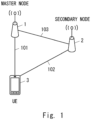
- Fig. 1 shows an example configuration of a radio communication network according to a plurality of embodiments including this embodiment.
- the radio communication network includes a RAN node 1, a RAN node 2, and a UE 3.
- Each element (or network function) shown in Fig. 1 can be implemented, for example, as a network element on dedicated hardware, as a software instance running on dedicated hardware, or as a virtualized function instantiated on an application platform.
- Each of the RAN nodes 1 and 2 may be a Next Generation (NG) RAN node, more specifically a gNB or ng-eNB.
- the ng-eNB is a node that provides Evolved Universal Mobile Telecommunications System (UMTS) Terrestrial Radio Access (E-UTRA) user plane and control plane protocol terminations towards a UE and is connected to a 5GC via an NG interface.
- the Radio Access Technology (RAT) of the RAN node 1 may be different from that of the RAN node 2.
- RAT Radio Access Technology
- the RAN node 1 may be a Central Unit (e.g., ng-eNB-CU or gNB-CU) in a cloud RAN (C-RAN) deployment, or a combination of a CU and one or more Distributed Units (e.g., ng-eNB-DUs or gNB-DUs).
- the C-RAN is also referred to as CU/DU split.
- the CU may include a Control Plane (CP) Unit (e.g., gNB-CU-CP) and one or more User Plane (UP) Units (e.g., gNB-CU-UPs).
- CP Control Plane
- UP User Plane
- the RAN node 1 may be a CU-CP or a combination of a CU-CP and a CU-UP(s).
- the RAN node 2 may be a Central Unit (CU) or a combination of a CU and one or more Distributed Units (DUs).
- the RAN node 2 may be a CU-CP or a combination of a CU-CP and a CU-UP(s).
- the RAN node 1 and the RAN node 2 communicate with each other via an inter-node interface (i.e., Xn interface) 103.
- the RAN node 1 and the RAN node 2 operate as an MN and an SN in dual connectivity, respectively.
- the UE 3 communicates with the MN 1 and the SN 2 via air interfaces 101 and 102 and performs dual connectivity between the MCG associated with the MN 1 and the SCG associated with the SN 2.
- This dual connectivity may be Multi-Radio Dual Connectivity (MR-DC). More specifically, the dual connectivity may be MR-DC with 5GC.
- the MR-DC with 5GC includes NG-RAN E-UTRA-NR Dual Connectivity (NGEN-DC), NR-E-UTRA Dual Connectivity (NE-DC), and NR-NR Dual Connectivity (NR-DC).
- the MN 1 may be either a master ng-eNB (in NGEN-DC) and a master gNB (in NR-DC and NE-DC).
- the SN 2 may be either a secondary ng-eNB (in NE-DC) and a secondary gNB (in NR-DC and NGEN-DC).
- the UE 3 is connected to an ng-eNB acting as the MN 1 and to a gNB acting as the SN 2.
- the UE 3 is connected to a gNB acting as the MN 1 and to an ng-eNB acting as the SN 2.
- the UE 3 is connected to one gNB (or gNB-DU) acting as the MN 1 and to another gNB (or gNB-DU) acting as the SN 2.
- the MCG is a group of serving cells associated with (or provided by) the MN 1.
- the MCG includes the SpCell (i.e., Primary Cell (PCell)) and optionally one or more Secondary Cells (SCells).
- the SCG is a group of serving cells associated with (or provided by) the SN 2.
- the SCG includes the Primary Cell of the SCG (i.e., Primary SCG Cell (PSCell)) and optionally one or more Secondary Cells (SCells).
- the PSCell is the Special Cell (SpCell) of the SCG and supports Physical Uplink Control Channel (PUCCH) transmission and contention-based Random Access.
- PUCCH Physical Uplink Control Channel
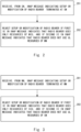
- Fig. 2 shows an example of the operation of the MN 1.
- the MN 1 receives from the SN 2 an XnAP message indicating the setup or modification of a radio bearer (SN terminated bearer) terminated at the SN 2.
- the XnAP message may request the MN 1 to add (or set up) or modify resources of the MN 1 for the SN terminated bearer.
- the XnAP message may request the MN 1 to prepare resources of the MN 1 for the SN terminated bearer or to prepare modifications of such resources.
- the XnAP message may be an SN ADDITION REQUEST ACKNOWLEDGE message, an SN MODIFICATION REQUEST ACKNOWLEDGE message, or an SN MODIFICATION REQUIRED message.
- the MN 1 rejects the setup or modification of the radio bearer (i.e., SN terminated bearer) if a first IE in the XnAP message indicates that the radio bearer uses only resources of the MCG, and if a second IE in the XnAP message indicates that the radio bearer does not use UL resources of the MN 1. In other words, the MN 1 does not admit the setup or modification of MN resources or MCG resources or both for the radio bearer.
- the first IE may be a Cell Group ID IE contained in an SN UL PDCP UP TNL Information IE contained in a DRBs to Be Setup Item IE (or DRBs to Be Modified Item IE) associated with the radio bearer (i.e., SN terminated bearer).
- the SN UL PDCP UP TNL Information IE refers to a UP Transport Parameters IE (Section 9.2.3.76 in Non-Patent Literature 2) and contains a UP Transport Layer Information IE and a Cell Group ID IE.
- the Cell Group ID IE can be set to only the value "0" meaning MCG, or only the value “1” meaning SCG, or both the value "0" and the value "1". If the Cell Group ID IE is only set to the value "0", this may indicate that the radio bearer uses only resources of the MCG.
- the second IE may be a UL Configuration IE contained in that DRBs to Be Setup Item IE (or DRBs to Be Modified Item IE).
- This UL Configuration IE indicates how the UE 3 will use the uplink of the corresponding RAN node (i.e., MN 1) for that radio bearer (i.e., SN terminated bearer). More specifically, the UL Configuration IE can be set to the value "no data", the value "shared", or the value "only”. The value "no data” means that the UE 3 does not use the uplink of the corresponding node (i.e., MN 1) for that radio bearer (i.e., SN terminated bearer).
- the value “shared” means that the UE 3 uses both the uplink of the corresponding node (i.e., MN 1) and the uplink of the other node (i.e., SN 2) for the radio bearer (i.e., SN terminated bearer).
- the value "only” means that the UE 3 uses only the uplink of the corresponding node (i.e., MN 1) for the radio bearer (i.e., SN terminated bearer).
- the MN 1 may act as follows to reject the setup or modification of the radio bearer in question (i.e., SN terminated bearer). After receiving an SN ADDITION REQUEST ACKNOWLEDGE (or SN MODIFICATION REQUEST ACKNOWLEDGE) message from the SN 2, the MN 1 may initiate an SN Release procedure to release the SN 2 (or to stop dual connectivity). Alternatively, after receiving a SN ADDITION REQUEST ACKNOWLEDGE (or SN MODIFICATION REQUEST ACKNOWLEDGE) message from the SN 2, the MN 1 may initiate an SN Modification procedure to request the SN 2 to release the radio bearer.
- SN ADDITION REQUEST ACKNOWLEDGE or SN MODIFICATION REQUEST ACKNOWLEDGE
- the MN 1 may send a SN MODIFICATION REFUSE message to the SN 2 indicating that the entire requested modification is not acceptable.
- the MN 1 may send an SN MODIFICATION CONFIRM message to the SN 2 indicating that modification of the MN resources for the radio bearer is not acceptable.
- Fig. 3 shows an example of the operation of the SN 2.
- the SN 2 receives from the MN 1 an XnAP message indicating the setup or modification of a radio bearer (MN terminated bearer) terminated at the MN 1.
- the XnAP message may request the SN 2 to add (or set up) or modify resources of the SN 2 for the MN terminated bearer.
- the XnAP message may request the SN 2 to prepare resources of the SN 2 for the MN terminated bearer or to prepare modifications of such resources.
- the XnAP message may be an SN ADDITION REQUEST message or an SN MODIFICATION REQUEST message.
- the SN 2 rejects the setup or modification of the radio bearer (i.e., MN terminated bearer) if a first IE in the XnAP message indicates that the radio bearer uses only resources of the SCG, and if a second IE in the XnAP message indicates that the radio bearer does not use UL resources of the SN 2. In other words, the SN 2 does not admit the setup or modification of SN resources or SCG resources or both for the radio bearer.
- MN terminated bearer i.e., MN terminated bearer
- the first IE may be a Cell Group ID IE contained in an MN UL PDCP UP TNL Information IE contained in a DRBs to Be Setup Item IE (or DRBs to Be Modified Item IE) associated with the radio bearer (i.e., MN terminated bearer).
- the MN UL PDCP UP TNL Information IE refers to a UP Transport Parameters IE (Section 9.2.3.76 in Non-Patent Literature 2) and contains a UP Transport Layer Information IE and a Cell Group ID IE.
- the Cell Group ID IE can be set to only the value "0" meaning MCG, or only the value "1” meaning SCG, or both the value "0" and the value "1". If the Cell Group ID IE is only set to the value "1", this may indicate that the radio bearer uses only resources of the SCG.
- the second IE may be a UL Configuration IE contained in that DRBs to Be Setup Item IE (or DRBs to Be Modified Item IE).
- This UL Configuration IE indicates how the UE 3 will use the uplink of the corresponding RAN node (i.e., SN 2) for that radio bearer (i.e., MN terminated bearer). More specifically, the UL Configuration IE can be set to the value "no data", the value "shared", or the value "only”. The value "no data” means that the UE 3 does not use the uplink of the corresponding node (i.e., SN 2) for that radio bearer (i.e., MN terminated bearer).
- the value “shared” means that the UE 3 uses both the uplink of the corresponding node (i.e., SN 2) and the uplink of the other node (i.e., MN 1) for the radio bearer (i.e., MN terminated bearer).
- the value "only” means that the UE 3 uses only the uplink of the corresponding node (i.e., SN 2) for the radio bearer (i.e., MN terminated bearer).
- the SN 2 may act as follows to reject the setup or modification of the radio bearer in question (i.e., MN terminated bearer).
- MN terminated bearer In response to receiving an SN ADDITION REQUEST (or SN MODIFICATION REQUEST) message from the MN 1, the SN 2 may send an SN ADDITION REQUEST REJECT (or SN MODIFICATION REQUEST REJECT) message to the MN 1. In other words, the SN 2 may reject the entire requested SN addition procedure (or SN modification procedure).
- the SN 2 may send an SN ADDITION REQUEST ACKNOWLEDGE (or SN MODIFICATION REQUEST ACKNOWLEDGE) message to the SN 2 indicating that the SN resource setup or modification for the radio bearer is not acceptable.
- the signaling shown in Fig. 4 relates to an SN addition procedure and an SN modification procedure.
- This SN addition procedure is an S-NG-RAN node Addition Preparation procedure.
- This SN modification procedure is an M-NG-RAN node initiated S-NG-RAN node Modification Preparation procedure.
- the MN 1 sends an S-NODE ADDITION REQUEST message to the SN 2.
- the S-NODE ADDITION REQUEST message informs the SN 2 of the setup of an MN terminated bearer with respect to a PDU Session of the UE 1.
- the S-NODE ADDITION REQUEST message requests the SN 2 to add or set up SN resources for an MN terminated bearer.
- the S-NODE ADDITION REQUEST message contains a PDU Session Resources To Be Added Item IE regarding the PDU Session in question.
- the PDU Session Resources To Be Added Item IE contains a PDU Session Resource Setup Info - MN terminated IE.
- the PDU Session Resource Setup Info - MN terminated IE contains a DRBs to Be Setup Item IE regarding the MN terminated bearer.
- the DRBs to Be Setup Item IE contains an MN UL PDCP UP TNL Information IE containing a Cell Group ID IE, and also contains a UL Configuration IE.
- the Cell Group ID IE is set to only the value "1", which implies that the MN terminated bearer is an SCG bearer.
- the UL Configuration IE is set to the value "no data", which indicates that the uplink of the SN 2 is not used for the MN terminated bearer.
- the MN 1 may instead send an S-NODE MODIFICATION REQUEST message to the SN 2.
- the S-NODE MODIFICATION REQUEST message informs the SN 2 of the setup or modification of an MN terminated bearer with respect to a PDU Session of the UE 1.
- the S-NODE MODIFICATION REQUEST message requests the SN 2 to add (or set up) or modify SN resources for an MN terminated bearer.
- the S-NODE MODIFICATION REQUEST message may contain a PDU Session Resources To Be Added Item IE regarding the setup of the PDU Session in question.
- the PDU Session Resources To Be Added Item IE contains a PDU Session Resource Setup Info - MN terminated IE.
- the S-NODE MODIFICATION REQUEST message may contain a PDU Session Resources To Be Modified Item IE regarding the modification of the PDU Session in question.
- the PDU Session Resources To Be Modified Item IE contains a PDU Session Resource Modification Info - MN terminated IE.
- the PDU Session Resource Setup Info - MN terminated IE contains a DRBs to Be Setup Item IE (or DRBs to Be Modified Item IE) pertaining to the MN terminated bearer.
- the DRBs to Be Setup Item IE contains an MN UL PDCP UP TNL Information IE containing a Cell Group ID IE, and also contains a UL Configuration IE.
- the Cell Group ID IE is set to only the value "1", which implies that the MN terminated bearer is an SCG bearer.
- the UL Configuration IE is set to the value "no data", which indicates that the uplink of the SN 2 is not used for the MN terminated bearer.
- the SN 2 determines whether to accept or reject the requested setup or modification of SN resources for the MN terminated bearer.
- the SN 2 recognizes that the UL Configuration IE within the DRBs to Be Setup Item IE (or DRBs to Be Modified Item IE) regarding the MN terminated bearer in question is set to the value "no data", and that the Cell Group ID IE contained in the MN UL PDCP UP TNL Information IE within that DRBs to Be Setup Item IE (or DRBs to Be Modified Item IE) is set to only the value "1", meaning SCG.
- the SN 2 decides to reject (or not admit) the setup or modification of SN resources for this MN terminated bearer.
- the SN 2 informs the MN 1 of its rejection of the requested MN terminated bearer setup or modification.
- the SN 2 may reject the entire S-NG-RAN node Addition Preparation procedure.
- the SN 2 may send an S-NODE ADDITION REQUEST REJECT message to the MN 1.
- a Cause IE contained in the S-NODE ADDITION REQUEST REJECT message may indicate, for example but not limited to, "invalid bearer Option configuration", "Invalid UL configuration", “Invalid UL resource configuration", or "Bearer Option not Valid".
- the SN 2 may selectively reject the setup of SN resources for the MN terminated bearer in question.
- the SN 2 may send to the MN 1 an S-NODE ADDITION REQUEST ACKNOWLEDGE message containing a PDU Session Resource Setup Response Info - MN terminated IE indicating that the setup of the MN terminated bearer is not acceptable.
- This PDU Session Resource Setup Response Info - MN terminated IE contains a DRBs Not Admitted To Be Setup or Modified List IE that includes the Data Radio Bearer (DRB) ID of the MN terminated bearer.
- the DRBs Not Admitted To Be Setup or Modified List IE may include a Cause IE associated with the MN terminated bearer. This Cause IE may indicate, for example but not limited to, "invalid bearer Option configuration", "Invalid UL configuration", “Invalid UL resource configuration”, or "Bearer Option not Valid”.
- the SN 2 may reject the entire S-NG-RAN node Modification Preparation procedure.
- the SN 2 may send an S-NODE MODIFICATION REQUEST REJECT message to the MN 1.
- a Cause IE contained in the S-NODE MODIFICATION REQUEST REJECT message may indicate, for example but not limited to, "invalid bearer Option configuration", "Invalid UL configuration", “Invalid UL resource configuration”, or "Bearer Option not Valid".
- the SN 2 may selectively reject the setup or modification of SN resources for the MN terminated bearer in question.
- the SN 2 may send to the MN 1 an S-NODE MODIFICATION REQUEST ACKNOWLEDGE message containing a PDU Session Resource Setup Response Info - MN terminated IE (or PDU Session Resource Modification Response Info - MN terminated IE) indicating that the setup or modification of the MN terminated bearer is not acceptable.
- This PDU Session Resource Setup Response Info - MN terminated IE (or PDU Session Resource Modification Response Info - MN terminated IE) contains a DRBs Not Admitted To Be Setup or Modified List IE that includes the DRB ID of the MN terminated bearer.
- the DRBs Not Admitted To Be Setup or Modified List IE may include a Cause IE associated with the MN terminated bearer.
- This Cause IE may indicate, for example but not limited to, "invalid bearer Option configuration”, “Invalid UL configuration”, “Invalid UL resource configuration”, or "Bearer Option not Valid”.
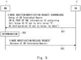
- the signaling shown in Fig. 5 relates to an SN addition procedure and an SN modification procedure.
- This SN addition procedure is an S-NG-RAN node Addition Preparation procedure.
- This SN modification procedure is an M-NG-RAN node initiated S-NG-RAN node Modification Preparation procedure.
- the SN 2 sends an S-NODE ADDITION REQUEST ACKNOWLEDGE message to the MN 1.
- the S-NODE ADDITION REQUEST ACKNOWLEDGE message informs the MN 1 of the setup of an SN terminated bearer for a PDU Session of the UE 1.
- the S-NODE ADDITION REQUEST ACKNOWLEDGE message requests the MN 1 to add or set up MN resources for an SN terminated bearer.
- the S-NODE ADDITION REQUEST ACKNOWLEDGE message contains a PDU Session Resources Admitted To Be Added Item IE for the PDU Session in question.
- the PDU Session Resources Admitted To Be Added Item IE contains a PDU Session Resource Setup Response Info - SN terminated IE.
- the PDU Session Resource Setup Response Info - SN terminated IE contains an SN UL PDCP UP TNL Information IE containing a Cell Group ID IE, and also contains a UL Configuration IE.
- the Cell Group ID IE is set to only the value "0", which implies that the SN terminated bearer is an MCG bearer.
- the UL Configuration IE is set to the value "no data", which indicates that the uplink of the MN 1 is not used for the SN terminated bearer.
- SN 2 may instead send an S-NODE MODIFICATION REQUEST ACKNOWLEDGE message to the MN 1.
- the S-NODE MODIFICATION REQUEST ACKNOWLEDGE message informs the MN 1 of the setup of an SN terminated bearer with respect to a PDU Session of the UE 1.
- the S-NODE MODIFICATION REQUEST ACKNOWLEDGE message requests the MN 1 to add or set up MN resources for an SN terminated bearer.
- the S-NODE MODIFICATION REQUEST ACKNOWLEDGE message may contain a PDU Session Resources Admitted To Be Added Item IE regarding the setup of the PDU Session in question.
- the PDU Session Resources Admitted To Be Added Item IE contains a PDU Session Resource Setup Response Info - SN terminated IE.
- the S-NODE MODIFICATION REQUEST ACKNOWLEDGE message may contain a PDU Session Resources Admitted To Be Modified Item IE regarding the modification of the PDU Session in question.
- the PDU Session Resources Admitted To Be Modified Item IE contains a PDU Session Resource Modification Response Info - SN terminated IE.
- the PDU Session Resource Setup Response Info - SN terminated IE (or PDU Session Resource Modification Response Info - SN terminated IE) contains a DRBs to Be Setup Item IE pertaining to the SN terminated bearer.
- the DRBs to Be Setup Item IE contains an SN UL PDCP UP TNL Information IE containing a Cell Group ID IE, and also contains a UL Configuration IE.
- the Cell Group ID IE is set to only the value "0", which implies that the SN terminated bearer is an MCG bearer.
- the UL Configuration IE is set to the value "no data", which indicates that the uplink of the MN 1 is not used for the SN terminated bearer.
- the MN 1 determines whether to accept or reject the requested setup of MN resources for the SN terminated bearer.
- the MN 1 recognizes that the UL Configuration IE in the DRBs to Be Setup Item IE regarding the SN terminated bearer in question is set to the value "no data", and that the Cell Group ID IE contained in the MN UL PDCP UP TNL Information IE within that DRBs to Be Setup Item IE is set to only the value "0", meaning MCG.
- the MN 1 decides to reject (or not admit) the setup of MN resources for this SN terminated bearer.
- the MN 1 informs the MN 1 of its rejection of the requested SN terminated bearer setup.
- the MN 1 may initiate an M-NG-RAN node initiated S-NG-RAN node Release procedure to release the SN 2 (or to stop dual connectivity).
- the MN 1 may send an S-NODE RELEASE REQUEST message to the SN 2.
- the MN 1 may selectively reject the setup of MN resources for the SN terminated bearer in question.
- the MN 1 may initiate an M-NG-RAN node initiated S-NG-RAN node Modification Preparation procedure to request the SN 2 to release the SN terminated bearer.
- the MN 1 may send an S-NODE MODIFICATION REQUEST message to the SN 2.
- the S-NODE MODIFICATION REQUEST message contains a PDU Session Resource Modification Info - SN terminated IE containing a DRBs To Be Released List IE that indicates the DRB ID of the SN terminated bearer.
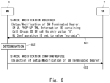
- the signaling shown in Fig. 6 relates to an SN modification procedure.
- This SN modification procedure is an S-NG-RAN node initiated S-NG-RAN node Modification procedure.
- the SN 2 sends an S-NODE MODIFICATION REQUIRED message to the MN 1.
- the S-NODE MODIFICATION REQUIRED message informs the MN 1 of the setup or modification of an SN terminated bearer with respect to a PDU Session of the UE 1.
- the S-NODE MODIFICATION REQUIRED message requests the MN 1 to add (or set up) or modify MN resources for an SN terminated bearer.
- the S-NODE MODIFICATION REQUIRED message may contain a PDU Session Resources To Be Modified Item IE regarding the modification of the PDU Session in question.
- the PDU Session Resources To Be Modified Item IE contains a PDU Session Resource Modification Required Info - SN terminated IE.
- the PDU Session Resource Modification Required Info - SN terminated IE contains a DRBs to Be Setup Item IE (or DRBs to Be Modified Item IE) regarding the SN terminated bearer.
- the DRBs to Be Setup Item IE (or DRBs to Be Modified Item IE) contains an SN UL PDCP UP TNL Information IE containing a Cell Group ID IE, and also contains a UL Configuration IE.
- the Cell Group ID IE is set to only the value "0", which implies that the SN terminated bearer is an MCG bearer.
- the UL Configuration IE is set to the value "no data", which indicates that the uplink of the MN 1 is not used for the SN terminated bearer.
- the MN 1 determines whether to accept or reject the requested setup or modification of MN resources for the SN terminated bearer.
- the MN 1 recognizes that the UL Configuration IE in the DRBs to Be Setup Item IE (or DRBs to Be Modified Item IE) regarding the SN terminated bearer in question is set to the value "no data", and that the Cell Group ID IE contained in the SN UL PDCP UP TNL Information IE within that DRBs to Be Setup Item IE (or DRBs to Be Modified Item IE) is set to only the value "0", meaning MCG.
- the MN 1 decides to reject (or not admit) the setup or modification of MN resources for this SN terminated bearer.
- the MN 1 notifies the SN 2 of its rejection of the requested SN terminated bearer setup or modification.
- the MN 1 may reject the entire S-NG-RAN node initiated S-NG-RAN node Modification procedure.
- the MN 1 may send an S-NODE MODIFICATION REFUSE message to the SN 2.
- a Cause IE in the S-NODE MODIFICATION REFUSE message may indicate, for example but not limited to, "invalid bearer Option configuration", "Invalid UL configuration", “Invalid UL resource configuration", or "Bearer Option not Valid".
- the MN 1 may selectively reject the setup or modification of SN resources for the SN terminated bearer in question.
- the MN 1 may send to the MN 1 a S-NODE MODIFICATION CONFIRM message containing a PDU Session Resource Modification Confirm Info - SN terminated IE indicating that the setup or modification of the SN terminated bearer in question is not acceptable.
- the PDU Session Resource Modification Confirm Info - SN terminated IE contains a DRBs Not Admitted To Be Setup or Modified List IE that includes the DRB ID of the SN terminated bearer.
- the DRBs Not Admitted To Be Setup or Modified List IE may include a Cause IE associated with the SN terminated bearer. This Cause IE may indicate, for example but not limited to, "invalid bearer Option configuration", "Invalid UL configuration", “Invalid UL resource configuration", or "Bearer Option not Valid".
- the MN 1 can reject the setup or modification of MN resources for that SN terminated bearer. This helps to avoid a situation where neither the MN (MCG) nor the SN (SCG) has an uplink configuration for the SN terminated bearer.
- the SN 2 can reject the setup or modification of SN resources for that MN terminated bearer. This helps to avoid a situation where there is no uplink configuration for the MN terminated bearer either in the MN (MCG) or in the SN (SCG).
- a configuration example of a radio communication network according to this embodiment is the same as the example shown in Fig. 1 .
- This embodiment provides other examples of the operations of the MN 1 and the SN 2.
- Fig. 7 shows an example of the operation of the MN 1.
- the MN 1 receives from the SN 2 an XnAP message indicating the setup or modification of a radio bearer (SN terminated bearer) terminated at the SN 2.
- the XnAP message may request the MN 1 to add (or set up) or modify resources of the MN 1 for the SN terminated bearer.
- the XnAP message may request the MN 1 to prepare resources of the MN 1 for the SN terminated bearer or to prepare modifications of such resources.
- the XnAP message may be an SN ADDITION REQUEST ACKNOWLEDGE message, an SN MODIFICATION REQUEST ACKNOWLEDGE message, or an SN MODIFICATION REQUIRED message.
- the MN 1 ignores a first IE contained in the XnAP message with respect to the SN endpoint of an Xn-U tunnel that is used for the delivery of UL PDUs, if a second IE in the XnAP message indicates that the radio bearer (i.e., SN terminated bearer) in question will not use the UL resources of the MN 1.
- the MN 1 ignores the SN endpoint information (SN UL Transport Layer information) indicated by the first IE. Accordingly, the MN 1 may not use the SN endpoint information.
- the MN 1 may discard the SN endpoint information.
- the MN 1 may omit (or skip) the preparation or setting of the delivery of UL PDUs destined for that SN endpoint.
- the first IE may be an SN UL PDCP UP TNL Information IE contained in a DRBs to Be Setup Item IE (or DRBs to Be Modified Item IE) associated with the radio bearer (i.e., SN terminated bearer).
- the first IE may be a UP Transport Layer Information IE contained in the SN UL PDCP UP TNL Information IE.
- the second IE may be a UL Configuration IE contained in that DRBs to Be Setup Item IE (or DRBs to Be Modified Item IE).
- This UL Configuration IE indicates how the UE 3 will use the uplink of the corresponding RAN node (i.e., MN 1) for that radio bearer (i.e., SN terminated bearer). More specifically, the UL Configuration IE can be set to the value "no data", the value "shared", or the value "only”. The value "no data” means that the UE 3 does not use the uplink of the corresponding node (i.e., MN 1) for that radio bearer (i.e., SN terminated bearer).
- the value “shared” means that the UE 3 uses both the uplink of the corresponding node (i.e., MN 1) and the uplink of the other node (i.e., SN 2) for the radio bearer (i.e., SN terminated bearer).
- the value "only” means that the UE 3 uses only the uplink of the corresponding node (i.e., MN 1) for the radio bearer (i.e., SN terminated bearer).
- Fig. 8 shows an example of the operation of the SN 2.
- the SN 2 receives from the MN 1 an XnAP message indicating the setup or modification of a radio bearer (MN terminated bearer) terminated at the MN 1.
- the XnAP message may request the SN 2 to add (or set up) or modify resources of the SN 2 for the MN terminated bearer.
- the XnAP message may request the SN 2 to prepare resources of the SN 2 for the MN terminated bearer or to prepare modifications of such resources.
- the XnAP message may be an SN ADDITION REQUEST message or an SN MODIFICATION REQUEST message.
- the SN 2 ignores a first IE contained in the XnAP message with respect to the MN endpoint of an Xn-U tunnel used for the delivery of UL PDUs, if a second IE in the XnAP message indicates that the radio bearer (i.e., MN terminated bearer) does not use UL resources of the SN 2. Accordingly, the SN 2 may not use the MN endpoint information. The SN 2 may discard the MN endpoint information. The SN 2 may omit (or skip) the preparation or setting of the delivery of UL PDUs destined for that MN endpoint.
- the first IE may be an MN UL PDCP UP TNL Information IE contained in a DRBs to Be Setup Item IE (or DRBs to Be Modified Item IE) associated with the radio bearer (i.e., MN terminated bearer).
- the first IE may be a UP Transport Layer Information IE contained in the MN UL PDCP UP TNL Information IE.
- the second IE may be a UL Configuration IE contained in that DRBs to Be Setup Item IE (or DRBs to Be Modified Item IE).
- This UL Configuration IE indicates how the UE 3 will use the uplink of the corresponding RAN node (i.e., SN 2) for that radio bearer (i.e., MN terminated bearer). More specifically, the UL Configuration IE can be set to the value "no data", the value "shared", or the value "only”. The value "no data” means that the UE 3 does not use the uplink of the corresponding node (i.e., SN 2) for that radio bearer (i.e., MN terminated bearer).
- the value “shared” means that the UE 3 uses both the uplink of the corresponding node (i.e., SN 2) and the uplink of the other node (i.e., MN 1) for the radio bearer (i.e., MN terminated bearer).
- the value "only” means that the UE 3 uses only the uplink of the corresponding node (i.e., SN 2) for the radio bearer (i.e., MN terminated bearer).
- the signaling shown in Fig. 9 relates to an SN addition procedure and an SN modification procedure.
- This SN addition procedure is an S-NG-RAN node Addition Preparation procedure.
- This SN modification procedure is an M-NG-RAN node initiated S-NG-RAN node Modification Preparation procedure.
- the MN 1 sends an S-NODE ADDITION REQUEST message to the SN 2.
- the S-NODE ADDITION REQUEST message informs the SN 2 of the setup of an MN terminated bearer with respect to a PDU Session of the UE 1.
- the S-NODE ADDITION REQUEST message requests the SN 2 to add or set up SN resources for an MN terminated bearer.
- the S-NODE ADDITION REQUEST message contains a PDU Session Resources To Be Added Item IE regarding the PDU Session in question.
- the PDU Session Resources To Be Added Item IE contains a PDU Session Resource Setup Info - MN terminated IE.
- the PDU Session Resource Setup Info - MN terminated IE contains a DRBs to Be Setup Item IE regarding the MN terminated bearer.
- the DRBs to Be Setup Item IE contains an MN UL PDCP UP TNL Information IE containing a Cell Group ID IE, and also contains a UL Configuration IE.
- the UL Configuration IE is set to the value "no data", which indicates that the uplink of the SN 2 is not used for the MN terminated bearer.
- the MN 1 may instead send an S-NODE MODIFICATION REQUEST message to the SN 2.
- the S-NODE MODIFICATION REQUEST message informs the SN 2 of the setup or modification of an MN terminated bearer with respect to a PDU Session of the UE 1.
- the S-NODE MODIFICATION REQUEST message requests the SN 2 to add (or set up) or modify SN resources for an MN terminated bearer.
- the S-NODE MODIFICATION REQUEST message may contain a PDU Session Resources To Be Added Item IE regarding the setup of the PDU Session in question.
- the PDU Session Resources To Be Added Item IE contains a PDU Session Resource Setup Info - MN terminated IE.
- the S-NODE MODIFICATION REQUEST message may contain a PDU Session Resources To Be Modified Item IE regarding the modification of the PDU Session in question.
- the PDU Session Resources To Be Modified Item IE contains a PDU Session Resource Modification Info - MN terminated IE.
- the PDU Session Resource Setup Info - MN terminated IE contains a DRBs to Be Setup Item IE (or DRBs to Be Modified Item IE) pertaining to the MN terminated bearer.
- the DRBs to Be Setup Item IE contains an MN UL PDCP UP TNL Information IE containing a Cell Group ID IE, and also contains a UL Configuration IE.
- the UL Configuration IE is set to the value "no data", which indicates that the uplink of the SN 2 is not used for the MN terminated bearer.
- the SN 2 recognizes that the UL Configuration IE within the DRBs to Be Setup Item IE (or DRBs to Be Modified Item IE) for the requested MN terminated bearer is set to the value "no data". Accordingly, the SN 2 ignores the UP Transport Layer information about the MN 1 as indicated by the MN UL PDCP UP TNL Information IE within that DRBs to Be Setup Item IE (or DRBs to Be Modified Item IE).
- the signaling shown in Fig. 10 relates to an SN addition procedure and an SN modification procedure.
- This SN addition procedure is an S-NG-RAN node Addition Preparation procedure.
- This SN modification procedure is an M-NG-RAN node initiated S-NG-RAN node Modification Preparation procedure.
- the SN 2 sends an S-NODE ADDITION REQUEST ACKNOWLEDGE message to the MN 1.
- the S-NODE ADDITION REQUEST ACKNOWLEDGE message informs the MN 1 of the setup of an SN terminated bearer for a PDU Session of the UE 1.
- the S-NODE ADDITION REQUEST ACKNOWLEDGE message requests the MN 1 to add or set up MN resources for an SN terminated bearer.
- the S-NODE ADDITION REQUEST ACKNOWLEDGE message contains a PDU Session Resources Admitted To Be Added Item IE for the PDU Session in question.
- the PDU Session Resources Admitted To Be Added Item IE contains a PDU Session Resource Setup Response Info - SN terminated IE.
- the PDU Session Resource Setup Response Info - SN terminated IE contains an SN UL PDCP UP TNL Information IE containing a Cell Group ID IE, and also contains a UL Configuration IE.
- the UL Configuration IE is set to the value "no data", which indicates that the uplink of the MN 1 is not used for the SN terminated bearer.
- SN 2 may instead send an S-NODE MODIFICATION REQUEST ACKNOWLEDGE message to the MN 1.
- the S-NODE MODIFICATION REQUEST ACKNOWLEDGE message requests the MN 1 to set up an SN terminated bearer with respect to a PDU Session of the UE 1.
- the S-NODE MODIFICATION REQUEST ACKNOWLEDGE message requests the MN 1 to add or set up MN resources for an SN terminated bearer.
- the S-NODE MODIFICATION REQUEST ACKNOWLEDGE message may contain a PDU Session Resources Admitted To Be Added Item IE regarding the setup of the PDU Session in question.
- the PDU Session Resources Admitted To Be Added Item IE contains a PDU Session Resource Setup Response Info - SN terminated IE.
- the S-NODE MODIFICATION REQUEST ACKNOWLEDGE message may contain a PDU Session Resources Admitted To Be Modified Item IE regarding the modification of the PDU Session in question.
- the PDU Session Resources Admitted To Be Modified Item IE contains a PDU Session Resource Modification Response Info - SN terminated IE.
- the PDU Session Resource Setup Response Info - SN terminated IE (or PDU Session Resource Modification Response Info - SN terminated IE) contains a DRBs to Be Setup Item IE pertaining to the SN terminated bearer.
- the DRBs to Be Setup Item IE contains an SN UL PDCP UP TNL Information IE containing a Cell Group ID IE, and also contains a UL Configuration IE.
- the UL Configuration IE is set to the value "no data", which indicates that the uplink of the MN 1 is not used for the SN terminated bearer.
- the MN 1 recognizes that the UL Configuration IE within the DRBs to Be Setup Item IE (or DRBs to Be Modified Item IE) for the requested SN terminated bearer is set to the value "no data". Accordingly, the MN 1 ignores the UP Transport Layer information about the SN 2 as indicated by the SN UL PDCP UP TNL Information IE within that DRBs to Be Setup Item IE (or DRBs to Be Modified Item IE).
- the signaling shown in Fig. 11 relates to an SN modification procedure.
- This SN modification procedure is an S-NG-RAN node initiated S-NG-RAN node Modification procedure.
- the SN 2 sends an S-NODE MODIFICATION REQUIRED message to the MN 1.
- the S-NODE MODIFICATION REQUIRED message informs the MN 1 of the setup or modification of an SN terminated bearer with respect to a PDU Session of the UE 1.
- the S-NODE MODIFICATION REQUIRED message requests the MN 1 to add (or set up) or modify MN resources for an SN terminated bearer.
- the S-NODE MODIFICATION REQUIRED message may contain a PDU Session Resources To Be Modified Item IE regarding the modification of the PDU Session in question.
- the PDU Session Resources To Be Modified Item IE contains a PDU Session Resource Modification Required Info - SN terminated IE.
- the PDU Session Resource Modification Required Info - SN terminated IE contains a DRBs to Be Setup Item IE (or DRBs to Be Modified Item IE) regarding the SN terminated bearer.
- the DRBs to Be Setup Item IE (or DRBs to Be Modified Item IE) contains an SN UL PDCP UP TNL Information IE containing a Cell Group ID IE, and also contains a UL Configuration IE.
- the UL Configuration IE is set to the value "no data", which indicates that the uplink of the MN 1 is not used for the SN terminated bearer.
- the MN 1 recognizes that the UL Configuration IE within the DRBs to Be Setup Item IE (or DRBs to Be Modified Item IE) pertaining to the requested SN terminated bearer is set to the value "no data". In response, the MN 1 ignores the UP transport layer information on the SN 2 indicated by the SN UL PDCP UP TNL Information IE within the DRBs to Be Setup Item IE (or DRBs to Be Modified Item IE).
- the MN 1 ignores the information about the SN endpoint received with respect to that SN terminated bearer. In this way, the MN 1 is not affected by the inconsistency between the Cell Group ID IE and the UL Configuration IE received from the SN 2 for the setup or modification of MN resources for the SN terminated bearer.
- the SN 2 ignores the information about the MN endpoint received with respect to that MN terminated bearer. In this way, the SN 2 is not affected by the inconsistency between the Cell Group ID IE and the UL Configuration IE received from the MN 1 for the setup or modification of SN resources for the MN terminated bearer.
- a configuration example of a radio communication network according to this embodiment is the same as the example shown in Fig. 1 .
- This embodiment provides other examples of the operations of the MN 1 and the SN 2.
- Fig. 12 shows an example of the operation of the MN 1.
- the MN 1 includes into an XnAP message to be sent to the SN 2 a first IE regarding a radio bearer (MN terminated bearer) terminated at the MN 1.
- the XnAP message may be an S-NODE ADDITION REQUEST message or an S-NODE MODIFICATION REQUEST message.
- the MN 1 includes into the XnAP message a second IE indicating how the UE 3 will use the uplink of the SN 2 for that radio bearer.
- the second IE is a conditional IE that is included in the XnAP message when the predetermined condition regarding the first IE is satisfied.
- the MN 1 sends the XnAP message to the SN 2.
- the first IE may be a Cell Group ID IE contained in an MN UL PDCP UP TNL Information IE contained in a DRBs to Be Setup Item IE (or DRBs to Be Modified Item IE) associated with the radio bearer (i.e., MN terminated bearer).
- the Cell Group ID IE can be set to only the value "0" meaning MCG, or only the value "1” meaning SCG, or both the value "0" and the value "1". If the Cell Group ID IE is set to both the value "0" and the value "1", this may indicate that the radio bearer (i.e., MN terminated bearer) uses both MCG resources and SCG resources.
- the first IE may be an IE different from the Cell Group ID IE described above.
- the first IE may be a new IE that indicates whether the radio bearer (i.e., MN terminated bearer) is an MCG bearer, split bearer, or SCG bearer.
- the new IE may be set to the value "MCG bearer", "split bearer", or "SCG bearer”.
- the name of the new IE may be, for example, but not limited to, Selected Bearer Type IE.
- the second IE may be a UL Configuration IE contained in that DRBs to Be Setup Item IE (or DRBs to Be Modified Item IE).
- This UL Configuration IE indicates how the UE 3 will use the uplink of the corresponding RAN node (i.e., SN 2) for that radio bearer (i.e., MN terminated bearer). More specifically, the UL Configuration IE can be set to the value "no data", the value "shared", or the value "only”. The value "no data” means that the UE 3 does not use the uplink of the corresponding node (i.e., SN 2) for that radio bearer (i.e., MN terminated bearer).
- the value “shared” means that the UE 3 uses both the uplink of the corresponding node (i.e., SN 2) and the uplink of the other node (i.e., MN 1) for the radio bearer (i.e., MN terminated bearer).
- the value "only” means that the UE 3 uses only the uplink of the corresponding node (i.e., SN 2) for the radio bearer (i.e., MN terminated bearer).
- Fig. 13 shows an example of the operation of the SN 2.
- the SN 2 includes into an XnAP message to be sent to the MN 1 a first IE regarding a radio bearer (SN terminated bearer) terminated at the SN 2.
- the XnAP message may be an S-NODE ADDITION REQUEST ACKNOWLEDGE message, an S-NODE MODIFICATION REQUEST ACKNOWLEDGE message, or an S-NODE MODIFICATION REQUIRED message.
- the MN 1 includes into the XnAP message a second IE indicating how the UE 3 will use the uplink of the MN 1 for that radio bearer.
- the second IE is a conditional IE that is included in the XnAP message when the predetermined condition regarding the first IE is satisfied.
- the SN 2 sends the XnAP message to the SN 2.
- the first IE may be a Cell Group ID IE contained in an SN UL PDCP UP TNL Information IE contained in a DRBs to Be Setup Item IE (or DRBs to Be Modified Item IE) associated with the radio bearer (i.e., SN terminated bearer).
- the Cell Group ID IE can be set to only the value "0" meaning MCG, or only the value "1" meaning SCG, or both the value "0" and the value "1". If the Cell Group ID IE is set to both the value "0" and the value "1", this may indicate that the radio bearer (i.e., SN terminated bearer) uses both MCG resources and SCG resources.
- the first IE may be an IE different from the Cell Group ID IE described above.
- the first IE may be a new IE that indicates whether the radio bearer (i.e., SN terminated bearer) is an MCG bearer, split bearer, or SCG bearer.
- the new IE may be set to the value "MCG bearer", "split bearer", or "SCG bearer”.
- the name of the new IE may be, for example, but not limited to, Selected Bearer Type IE.
- the second IE may be a UL Configuration IE contained in that DRBs to Be Setup Item IE (or DRBs to Be Modified Item IE).
- This UL Configuration IE indicates how the UE 3 will use the uplink of the corresponding RAN node (i.e., MN 1) for that radio bearer (i.e., SN terminated bearer). More specifically, the UL Configuration IE can be set to the value "no data", the value "shared", or the value "only”. The value "no data” means that the UE 3 does not use the uplink of the corresponding node (i.e., MN 1) for that radio bearer (i.e., SN terminated bearer).
- the value “shared” means that the UE 3 uses both the uplink of the corresponding node (i.e., MN 1) and the uplink of the other node (i.e., SN 2) for the radio bearer (i.e., SN terminated bearer).
- the value "only” means that the UE 3 uses only the uplink of the corresponding node (i.e., MN 1) for the radio bearer (i.e., SN terminated bearer).
- the MN 1 includes into the XnAP message a second IE indicating how the UE 3 will use the uplink of the SN 2 for the MN terminated bearer. This allows the MN 1 to prevent any inconsistencies between the first IE and the second IE.
- the SN 2 includes into the XnAP message a second IE indicating how the UE 3 will use the uplink of the MN 1 for the SN terminated bearer. This allows the SN 2 to prevent any inconsistencies between the first IE and the second IE.
- Fig. 14 is a block diagram showing a configuration example of the MN 1 according to the above-described embodiments.
- the configuration of the SN 2 may be the same as that shown in Fig. 14 .
- the MN 1 includes a Radio Frequency transceiver 1401, a network interface 1403, a processor 1404, and a memory 1405.
- the RF transceiver 1401 performs analog RF signal processing to communicate with UEs including the UE 3.
- the RF transceiver 1401 may include a plurality of transceivers.
- the RF transceiver 1401 is coupled to an antenna array 1402 and the processor 1404.
- the RF transceiver 1401 receives modulation symbol data from the processor 1404, generates a transmission RF signal, and supplies the transmission RF signal to the antenna array 1402.
- the RF transceiver 1401 generates a baseband reception signal based on a reception RF signal received by the antenna array 1402 and supplies the baseband reception signal to the processor 1404.
- the RF transceiver 1401 may include an analog beamformer circuit for beamforming.
- the analog beamformer circuit includes, for example, a plurality of phase shifters and a plurality of power amplifiers.
- the network interface 1403 is used to communicate with network nodes (e.g., MN 1, and control node and transfer node of a core network).
- the network interface 1403 may include, for example, a Network Interface Card (NIC) that is compliant with IEEE 802.3 series.
- NIC Network Interface Card
- the processor 1404 performs digital baseband signal processing (data-plane processing) and control-plane processing for radio communication.
- the processor 1404 may include a plurality of processors.
- the processor 1404 may include a modem processor (e.g., Digital Signal Processor (DSP)) for performing the digital baseband signal processing and a protocol stack processor (e.g., Central Processing Unit (CPU) or Micro Processing Unit (MPU)) for performing the control-plane processing.
- DSP Digital Signal Processor
- the processor 1404 may include a digital beamformer module for beamforming.
- the digital beamformer module may include a Multiple Input Multiple Output (MIMO) encoder and precoder.
- MIMO Multiple Input Multiple Output
- the memory 1405 is composed of a combination of a volatile memory and a non-volatile memory.
- the volatile memory is, for example, a Static Random Access Memory (SRAM), a Dynamic RAM (DRAM), or a combination thereof.
- the non-volatile memory may be a Mask Read Only Memory (MROM), an Electrically Erasable Programmable ROM (EEPROM), a flash memory, or a hard disk drive, or any combination thereof.
- the memory 1405 may include a storage located away from the processor 1404. In this case, the processor 1404 may access the memory 1405 via the network interface 1403 or an I/O interface not shown.
- the memory 1405 may store one or more software modules (computer programs) 1406 including instructions and data for performing processing by the MN 1 described in the above embodiments.
- the processor 1404 may be configured to load and execute the software module(s) 1406 from the memory 1405, thereby performing the processing of the MN 1 described in the above embodiments.
- the MN 1 (or SN 2) is a CU (e.g., eNB-CU or gNB-CU) or a CU-CP, the MN 1 (or SN 2) does not have to include the RF transceiver 1401 (and the antenna array 1402).
- each of the processors in the MN 1 and SN 2 executes one or more programs, containing a set of instructions, to cause a computer to perform an algorithm described with reference to the drawings.
- These programs can be stored and provided to a computer using any type of non-transitory computer readable media.
- Non-transitory computer readable media include any type of tangible storage media.
- non-transitory computer readable media examples include magnetic storage media (such as flexible disks, magnetic tapes, hard disk drives, etc.), optical magnetic storage media (e.g., magneto-optical disks), Compact Disc Read Only Memory (CD-ROM), CD-R, CD-R/W, and semiconductor memories (such as mask ROM, Programmable ROM (PROM), Erasable PROM (EPROM), flash ROM, Random Access Memory (RAM), etc.).
- These programs may be provided to a computer using any type of transitory computer readable media. Examples of transitory computer readable media include electric signals, optical signals, and electromagnetic waves. Transitory computer readable media can provide the programs to a computer via a wired communication line (e.g., electric wires, and optical fibers) or a wireless communication line.
- a first radio access network (RAN) node comprising:
- the first RAN node according to Supplementary Note 9, wherein the rejection of the setup of the radio bearer includes rejecting the M-NG-RAN node initiated S-NG-RAN node Modification Preparation procedure by sending an S-NODE MODIFICATION REQUEST REJECT message to the MN.
- the first RAN node according to Supplementary Note 9, wherein the rejection of the setup of the radio bearer includes sending to the MN an S-NODE MODIFICATION REQUEST ACKNOWLEDGE message containing a PDU Session Resource Modification Response Info - MN terminated IE indicating that the setup of the radio bearer is not acceptable.
- the first RAN node according to Supplementary Note 15, wherein the rejection of the setup of the radio bearer includes initiating an M-NG-RAN node initiated S-NG-RAN node Release procedure.
- the first RAN node according to Supplementary Note 15, wherein the rejection of the setup of the radio bearer includes initiating an M-NG-RAN node initiated S-NG-RAN node Modification Preparation procedure to release the radio bearer.
- the first RAN node according to Supplementary Note 18, wherein the rejection of the setup of the radio bearer includes initiating an M-NG-RAN node initiated S-NG-RAN node Release procedure.
- the first RAN node according to Supplementary Note 18, wherein the rejection of the setup of the radio bearer includes initiating an M-NG-RAN node initiated S-NG-RAN node Modification Preparation procedure to release the radio bearer.
- the first RAN node according to Supplementary Note 21, wherein the rejection of the setup of the radio bearer includes initiating an M-NG-RAN node initiated S-NG-RAN node Release procedure.
- the first RAN node according to Supplementary Note 21, wherein the rejection of the setup of the radio bearer includes initiating an M-NG-RAN node initiated S-NG-RAN node Modification Preparation procedure to release the radio bearer.
- the first RAN node according to Supplementary Note 24, wherein the rejection of the setup of the radio bearer includes rejecting the S-NG-RAN node initiated S-NG-RAN node Modification procedure.
- the first RAN node according to Supplementary Note 24, wherein the rejection of the setup of the radio bearer includes sending to the SN an S-NODE MODIFICATION CONFIRM message containing a PDU Session Resource Modification Confirm Info - SN terminated IE indicating that the setup of the radio bearer is not acceptable.
- a method performed by a first radio access network (RAN) node comprising:
- a first radio access network (RAN) node comprising:
- a method performed by a first radio access network (RAN) node comprising:
- a radio access network (RAN) node configured to act as a master node (MN) for dual connectivity for a User Equipment (UE), comprising:
- the Cell Group ID IE indicates that the radio bearer will use both resources in the Master Cell Group (MCG) of the MN and resources in the Secondary Cell Group (SCG) of the SN.
- a radio access network (RAN) node configured to act as a secondary node (SN) for dual connectivity for a User Equipment (UE), comprising:
- the RAN node according to Supplementary Note 40 wherein the first message is an S-NODE ADDITION REQUEST ACKNOWLEDGE message, an S-NODE MODIFICATION REQUEST ACKNOWLEDGE message, or an S-NODE MODIFICATION REQUIRED message.
- the Cell Group ID IE indicates that the radio bearer will use both resources in the Master Cell Group (MCG) of the MN and resources in the Secondary Cell Group (SCG) of the SN.
- a method of a secondary base station in Dual Connectivity comprising:
- the UL Configuration information element is an information element indicating how a terminal device uses an uplink of the secondary base station.
- a method of a master base station in Dual Connectivity comprising:
- the UL Configuration information element is an information element indicating how a terminal device uses an uplink of the secondary base station.
- a secondary base station in Dual Connectivity comprising a receiver and a transmitter, wherein
- the secondary base station according to Supplementary Note A11, wherein the UL Configuration information element is an information element indicating how a terminal device uses an uplink of the secondary base station.
- the secondary base station according to Supplementary Note A11 or A12, wherein the transmitter is configured to include into the request acknowledge message a Cell Group ID information element meaning that the secondary base station will use the SN terminated bearer that uses both resources in the Master Cell Group (MCG) and resources in the Secondary Cell Group (SCG).
- MCG Master Cell Group
- SCG Secondary Cell Group
- the secondary base station according to any one of Supplementary Notes A11 to A13, wherein the request acknowledge message is an S-NODE ADDITION REQUEST ACKNOWLEDGE message or an S-NODE MODIFICATION REQUEST ACKNOWLEDGE message.
- the secondary base station according to any one of Supplementary Notes A11 to A14, wherein the request message is an S-NODE ADDITION REQUEST message or an S-NODE MODIFICATION REQUEST message.
- a master base station in Dual Connectivity comprising a transmitter and a receiver, wherein
- the UL Configuration information element is an information element indicating how a terminal device uses an uplink of the secondary base station.
- the master base station according to Supplementary Note A16 or A17, wherein the receiver is configured to receive the request acknowledge message containing a Cell Group ID information element meaning that the secondary base station will use the SN terminated bearer that uses both resources in the Master Cell Group (MCG) and resources in the Secondary Cell Group (SCG).
- MCG Master Cell Group
- SCG Secondary Cell Group
- the master base station according to any one of Supplementary Notes A16 to A18, wherein the request acknowledge message is an S-NODE ADDITION REQUEST ACKNOWLEDGE message or an S-NODE MODIFICATION REQUEST ACKNOWLEDGE message.
- the master base station according to any one of Supplementary Notes A16 to A19, wherein the request message is an S-NODE ADDITION REQUEST message or an S-NODE MODIFICATION REQUEST message.
Landscapes
- Engineering & Computer Science (AREA)
- Signal Processing (AREA)
- Computer Networks & Wireless Communication (AREA)
- Mobile Radio Communication Systems (AREA)
Abstract
Description
- The present disclosure relates to a radio communication system, and in particular to signaling between radio access network nodes for multi-connectivity (e.g., Dual Connectivity).
- The 3rd Generation Partnership Project (3GPP) specifies signaling between Radio Access Network (RAN) nodes in Multi-Radio Dual Connectivity (MR-DC), i.e., between a Master Node (MN) and a Secondary Node (SN) (see, for example,
Non-Patent Literature 1 and 2). In MR-DC, the MN is a RAN node that provides a control plane connection to the core network to the User Equipment (UE), while the SN is a RAN node that does not provide that control plane connection to the UE. In MR-DC, the group of one or more serving cells associated with the MN is referred to as the Master Cell Group (MCG) and the group of one or more serving cells associated with the SN is referred to as the Secondary Cell Group (SCG). - For example, the MN can request the SN to add or modify SN resources related to a PDU Session via a SN ADDITION REQUEST or SN MODIFICATION REQUEST message. With these messages, the MN can request the SN to set up or modify SCG resources for a bearer (MN terminated bearer) terminated at the MN. In MR-DC, an MN terminated bearer is a data radio bearer for which the Packet Data Convergence Protocol (PDCP) is placed in the MN. An MN terminated bearer that requires SCG resources is an MN terminated SCG bearer or an MN terminated split bearer. An SCG bearer is a radio bearer having its Radio Link Control (RLC) bearer only within the SCG. A Split bearer is a radio bearer that has both an RLC bearer in the MCG and an RLC bearer in the SCG. These MN terminated bearers that require SCG resources need resources (i.e., an Xn-U bearer or Xn-U tunnel) on a user plane interface (i.e., Xn-U interface) between the MN and the SN for delivery of PDCP data (i.e., PDCP Protocol Data Units (PDUs)).
- In addition, for example, the SN can request the MN to add or modify MN resources related to a PDU Session via SN ADDITION REQUEST ACKNOWLEDGE, SN MODIFICATION REQUEST ACKNOWLEDGE, or SN MODIFICATION REQUIRED message. Using these messages, the SN can request the MN to set up MCG resources for a bearer (SN terminated bearer) terminated at the SN. An SN terminated bearer is a data radio bearer for which the PDCP is placed in the SN. An SN terminated bearer that requires MCG resources is an SN terminated MCG bearer or an SN terminated split bearer. An MCG bearer is a radio bearer that has its RLC bearer only within the MCG. These SN terminated bearers that require MCG resources need resources (i.e., an Xn-U bearer or Xn-U tunnel) on a user plane interface (i.e., Xn-U interface) between the MN and the SN for delivery of PDCP data (i.e., PDCP PDUs).
-
- [Non-Patent Literature 1] 3GPP TS 37.340 V15.10.0 (2020-09) "3rd Generation Partnership Project; Technical Specification Group Radio Access Network; Evolved Universal Terrestrial Radio Access (E-UTRA) and NR; Multi-connectivity; Stage 2 (Release 15)", September 2020
- [Non-Patent Literature 2] 3GPP TS 38.423 V15.9.0 (2020-09) "3rd Generation Partnership Project; Technical Specification Group Radio Access Network; NG-RAN; Xn application protocol (XnAP) (Release 15)", September 2020
- According to the current 3GPP specifications, when requesting the SN to setup SCG resources for an MN terminated bearer, the MN includes into a SN MODIFICATION REQUEST message a PDU Session Resource Setup Info - MN terminated information element (IE) containing a DRBs to Be Setup Item IE associated with the MN terminated bearer. This DRBs to Be Setup Item IE can include a UL Configuration IE. In the current specifications, the UL Configuration IE is optional. The UL Configuration IE indicates how the UE will use the uplink of the SN for the MN terminated bearer. More specifically, the UL Configuration IE can be set to the value "no data", the value "shared", or the value "only". The value "no data" means that the
UE 3 does not use the uplink of the corresponding node (i.e., SN) for the radio bearer in question (i.e., MN terminated bearer). The value "shared" means that the UE uses both the uplink of the corresponding node (i.e., SN) and the uplink of the other node (i.e., MN) for the radio bearer (i.e., MN terminated bearer). The value "only" means that the UE uses only the uplink of the corresponding node (i.e., SN) for the radio bearer (i.e., MN terminated bearer). - On the other hand, under the current 3GPP specifications, an MN UL PDCP UP TNL Information IE is mandatory within the DRBs to Be Setup Item IE mentioned above. As described in
Non-Patent Literature 2, the MN UL PDCP UP TNL Information IE refers to a UP Transport Parameters IE (Section 9.2.3.76 of Non-Patent Literature 2) and contains a UP Transport Layer Information IE and a Cell Group ID IE. Both the UP Transport Layer Information IE and the Cell Group ID IE are mandatory information elements. The UP Transport Layer Information IE indicates the MN endpoint of an Xn-U bearer for delivery of uplink (UL) PDCP PDUs for the MN terminated bearer. The Cell Group ID IE can be set to only the value "0" meaning MCG, or only the value "1" meaning SCG, or both the value "0" and the value "1". Accordingly, although it is not explicitly stated in the current 3GPP specifications, it is assumed that the Cell Group ID IE set to the value "0" means an MCG bearer, the Cell Group ID IE set to the value "1" means an SCG bearer, and the Cell Group ID IE set to both the value "0" and "1" means a split bearer. - However, inconsistency may occur between the above-mentioned Cell Group ID IE and the above-mentioned UL Configuration IE. For example, in the case of the setup of SCG resource for an MN terminated bearer described above, the UL Configuration IE may be set to the value "no data" while the Cell Group ID IE is set to the value "1". In other words, it could happen that the Cell Group ID IE implies that the MN terminated bearer is an SCG bearer, but the UL Configuration IE indicates that the UL of the SN is not used. According to the current 3GPP specifications, it is not clear how the SN understands these IEs in this case. This may lead to a situation where, in the worst case, the SN does not configure any UL resources for the UE and there is no uplink configuration for the MN terminated bearer, neither in the MN (MCG) nor in the SN (SCG).
- The problem described above can also occur when the MN requests the SN to modify SCG resources for an MN terminated bearer. Similarly, this problem can also occur when the SN requests the MN to set up or modify MCG resources for an SN terminated bearer.
- One of the objects to be attained by embodiments disclosed herein is to provide apparatuses, methods, and programs that contribute to solving the problems described above. It should be noted that this object is merely one of the objects to be attained by the embodiments disclosed herein. Other objects or problems and novel features will be made apparent from the following description and the accompanying drawings.
- In a first aspect, a first RAN node includes at least one memory and at least one processor coupled to the at least one memory. The at least one processor is configured to receive from a second RAN node, in a control procedure for dual connectivity for a User Equipment (UE), a first message indicating a setup or modification of a radio bearer terminated at the second RAN node. The at least one processor is configured to reject the setup or modification of the radio bearer if a first IE in the first message indicates that the radio bearer will only use resources in a cell group of the first RAN node, and if a second IE in the first message indicates that the UE will not use an uplink of the first RAN node for the radio bearer.
- In a second aspect, a method performed by a first RAN node includes the steps of:
- (a) receiving from a second RAN node, in a control procedure for dual connectivity for a User Equipment (UE), a first message indicating a setup or modification of a radio bearer terminated at the second RAN node; and
- (b) rejecting the setup or modification of the radio bearer if a first IE in the first message indicates that the radio bearer will only use resources in a cell group of the first RAN node, and if a second IE in the first message indicates that the UE will not use an uplink of the first RAN node for the radio bearer.
- In a third aspect, a first RAN node includes at least one memory and at least one processor coupled to the at least one memory. The at least one processor is configured to receive from a second RAN node, in a control procedure for dual connectivity for a User Equipment (UE), a first message indicating a setup or modification of a radio bearer terminated at the second RAN node. The at least one processor is configured to ignore a first IE contained in the first message with respect to an endpoint of the second RAN node in an inter-RAN node tunnel used for delivery of uplink PDUs if a second IE in the first message indicates that the UE will not use an uplink of the first RAN node for the radio bearer.
- In a fourth aspect, a method performed by a first RAN node includes the steps of:
- (a) receiving from a second RAN node, in a control procedure for dual connectivity for a User Equipment (UE), a first message indicating a setup or modification of a radio bearer terminated at the second RAN node; and
- (b) ignoring a first IE contained in the first message with respect to an endpoint of the second RAN node in an inter-RAN node tunnel used for delivery of uplink PDUs if a second IE in the first message indicates that the UE will not use an uplink of the first RAN node for the radio bearer.
- In a fifth aspect, a RAN node, configured to act as an MN for dual connectivity for a UE, includes at least one memory and at least one processor coupled to the at least one memory. The at least one processor is configured to include, into a first message to be sent to an SN of the dual connectivity, a first IE regarding a radio bearer terminated at the MN. The at least one processor is configured to, on a condition that the first IE indicates that the radio bearer will use both resources in an MCG of the MN and resources in an SCG of the SN, include into the first message a second IE indicating how the UE will use an uplink of the SN for the radio bearer. The at least one processor is configured to send the first message to the SN.
- In a sixth aspect, a method performed by a RAN node, configured to act as an MN for dual connectivity for a UE, includes the steps of:
- (a) including, into a first message to be sent to an SN of the dual connectivity, a first IE regarding a radio bearer terminated at the MN;
- (b) on a condition that the first IE indicates that the radio bearer will use both resources in an MCG of the MN and resources in an SCG of the SN, including into the first message a second IE indicating how the UE will use an uplink of the SN for the radio bearer; and
- (c) sending the first message to the SN.
- In a seventh aspect, a RAN node, configured to act as an SN for dual connectivity for a UE, includes at least one memory and at least one processor coupled to the at least one memory. The at least one processor is configured to include, into a first message to be sent to an MN of the dual connectivity, a first IE regarding a radio bearer terminated at the SN. The at least one processor is configured to, on a condition that the first IE indicates that the radio bearer will use both resources in an MCG of the MN and resources in an SCG of the SN, include into the first message a second IE indicating how the UE will use an uplink of the MN for the radio bearer. The at least one processor is configured to send the first message to the MN.
- In an eighth aspect, a method performed by a RAN node, configured to act as an SN for dual connectivity for a UE, includes the steps of:
- (a) including, into a first message to be sent to an MN of the dual connectivity, a first IE regarding a radio bearer terminated at the SN;
- (b) on a condition that the first IE indicates that the radio bearer will use both resources in an MCG of the MN and resources in an SCG of the SN, including into the first message a second IE indicating how the UE will use an uplink of the MN for the radio bearer; and
- (c) sending the first message to the MN.
- In a ninth aspect, a program includes a set of instructions (software codes) that, when loaded into a computer, cause the computer to perform the method according to the second, fourth, sixth, or eighth aspect described above.
- According to the above-described aspects, it is possible to provide apparatuses, methods, and programs that contribute to solving the above-mentioned problems.
-
-
Fig. 1 shows an example configuration of a radio communication network according to an embodiment; -
Fig. 2 is a flowchart showing an example of the operation of an MN according to an embodiment; -
Fig. 3 is a flowchart showing an example of the operation of an SN according to an embodiment; -
Fig. 4 is a sequence diagram showing an example of signaling according to an embodiment; -
Fig. 5 is a sequence diagram showing an example of signaling according to an embodiment; -
Fig. 6 is a sequence diagram showing an example of signaling according to an embodiment; -
Fig. 7 is a flowchart showing an example of the operation of an MN according to an embodiment; -
Fig. 8 is a flowchart showing an example of the operation of an SN according to an embodiment; -
Fig. 9 is a sequence diagram showing an example of signaling according to an embodiment; -
Fig. 10 is a sequence diagram showing an example of signaling according to an embodiment; -
Fig. 11 is a sequence diagram showing an example of signaling according to an embodiment; -
Fig. 12 is a flowchart showing an example of the operation of an MN according to an embodiment; -
Fig. 13 is a flowchart showing an example of the operation of an SN according to an embodiment; and -
Fig. 14 is a block diagram showing an example configuration of an MN and an SN according to an embodiment. - Specific embodiments will be described hereinafter in detail with reference to the drawings. The same or corresponding elements are denoted by the same symbols throughout the drawings, and duplicated explanations are omitted as necessary for the sake of clarity.
- Each of the embodiments described below may be used individually, or two or more of the embodiments may be appropriately combined with one another. These embodiments include novel features different from each other. Accordingly, these embodiments contribute to attaining objects or solving problems different from one another and contribute to obtaining advantages different from one another.
- The following descriptions on the embodiments mainly focus on the 3GPP Long Term Evolution (LTE) system and fifth generation mobile communication system (5G system). More specifically, the embodiments will be described primarily for MR-DC with 5G Core (5GC). However, these embodiments may be applied to other radio communication systems that support technologies similar to the multi-connectivity (e.g., Dual Connectivity) in the 3GPP. The term LTE as used herein includes improvements and enhancements to LTE and LTE-Advanced to enable interworking with the 5G System, unless otherwise noted.
-
Fig. 1 shows an example configuration of a radio communication network according to a plurality of embodiments including this embodiment. In the example ofFig. 1 , the radio communication network includes aRAN node 1, aRAN node 2, and aUE 3. Each element (or network function) shown inFig. 1 can be implemented, for example, as a network element on dedicated hardware, as a software instance running on dedicated hardware, or as a virtualized function instantiated on an application platform. - Each of the
RAN nodes RAN node 1 may be different from that of theRAN node 2. - The
RAN node 1 may be a Central Unit (e.g., ng-eNB-CU or gNB-CU) in a cloud RAN (C-RAN) deployment, or a combination of a CU and one or more Distributed Units (e.g., ng-eNB-DUs or gNB-DUs). The C-RAN is also referred to as CU/DU split. The CU may include a Control Plane (CP) Unit (e.g., gNB-CU-CP) and one or more User Plane (UP) Units (e.g., gNB-CU-UPs). Accordingly, theRAN node 1 may be a CU-CP or a combination of a CU-CP and a CU-UP(s). Similarly, theRAN node 2 may be a Central Unit (CU) or a combination of a CU and one or more Distributed Units (DUs). TheRAN node 2 may be a CU-CP or a combination of a CU-CP and a CU-UP(s). - The
RAN node 1 and theRAN node 2 communicate with each other via an inter-node interface (i.e., Xn interface) 103. TheRAN node 1 and theRAN node 2 operate as an MN and an SN in dual connectivity, respectively. TheUE 3 communicates with theMN 1 and theSN 2 viaair interfaces MN 1 and the SCG associated with theSN 2. - This dual connectivity may be Multi-Radio Dual Connectivity (MR-DC). More specifically, the dual connectivity may be MR-DC with 5GC. The MR-DC with 5GC includes NG-RAN E-UTRA-NR Dual Connectivity (NGEN-DC), NR-E-UTRA Dual Connectivity (NE-DC), and NR-NR Dual Connectivity (NR-DC). Accordingly, the
MN 1 may be either a master ng-eNB (in NGEN-DC) and a master gNB (in NR-DC and NE-DC). Similarly, theSN 2 may be either a secondary ng-eNB (in NE-DC) and a secondary gNB (in NR-DC and NGEN-DC). In NGEN-DC, theUE 3 is connected to an ng-eNB acting as theMN 1 and to a gNB acting as theSN 2. In NE-DC, theUE 3 is connected to a gNB acting as theMN 1 and to an ng-eNB acting as theSN 2. In NR-DC, theUE 3 is connected to one gNB (or gNB-DU) acting as theMN 1 and to another gNB (or gNB-DU) acting as theSN 2. - The MCG is a group of serving cells associated with (or provided by) the
MN 1. The MCG includes the SpCell (i.e., Primary Cell (PCell)) and optionally one or more Secondary Cells (SCells). Meanwhile, the SCG is a group of serving cells associated with (or provided by) theSN 2. The SCG includes the Primary Cell of the SCG (i.e., Primary SCG Cell (PSCell)) and optionally one or more Secondary Cells (SCells). The PSCell is the Special Cell (SpCell) of the SCG and supports Physical Uplink Control Channel (PUCCH) transmission and contention-based Random Access. - The following describes examples of the operations of the
MN 1 and theSN 2 according to this embodiment.Fig. 2 shows an example of the operation of theMN 1. Instep 201, theMN 1 receives from theSN 2 an XnAP message indicating the setup or modification of a radio bearer (SN terminated bearer) terminated at theSN 2. The XnAP message may request theMN 1 to add (or set up) or modify resources of theMN 1 for the SN terminated bearer. The XnAP message may request theMN 1 to prepare resources of theMN 1 for the SN terminated bearer or to prepare modifications of such resources. The XnAP message may be an SN ADDITION REQUEST ACKNOWLEDGE message, an SN MODIFICATION REQUEST ACKNOWLEDGE message, or an SN MODIFICATION REQUIRED message. Instep 202, theMN 1 rejects the setup or modification of the radio bearer (i.e., SN terminated bearer) if a first IE in the XnAP message indicates that the radio bearer uses only resources of the MCG, and if a second IE in the XnAP message indicates that the radio bearer does not use UL resources of theMN 1. In other words, theMN 1 does not admit the setup or modification of MN resources or MCG resources or both for the radio bearer. - In some implementations, the first IE may be a Cell Group ID IE contained in an SN UL PDCP UP TNL Information IE contained in a DRBs to Be Setup Item IE (or DRBs to Be Modified Item IE) associated with the radio bearer (i.e., SN terminated bearer). As described in
Non-Patent Literature 2, the SN UL PDCP UP TNL Information IE refers to a UP Transport Parameters IE (Section 9.2.3.76 in Non-Patent Literature 2) and contains a UP Transport Layer Information IE and a Cell Group ID IE. The Cell Group ID IE can be set to only the value "0" meaning MCG, or only the value "1" meaning SCG, or both the value "0" and the value "1". If the Cell Group ID IE is only set to the value "0", this may indicate that the radio bearer uses only resources of the MCG. - Meanwhile, the second IE may be a UL Configuration IE contained in that DRBs to Be Setup Item IE (or DRBs to Be Modified Item IE). This UL Configuration IE indicates how the
UE 3 will use the uplink of the corresponding RAN node (i.e., MN 1) for that radio bearer (i.e., SN terminated bearer). More specifically, the UL Configuration IE can be set to the value "no data", the value "shared", or the value "only". The value "no data" means that theUE 3 does not use the uplink of the corresponding node (i.e., MN 1) for that radio bearer (i.e., SN terminated bearer). The value "shared" means that theUE 3 uses both the uplink of the corresponding node (i.e., MN 1) and the uplink of the other node (i.e., SN 2) for the radio bearer (i.e., SN terminated bearer). The value "only" means that theUE 3 uses only the uplink of the corresponding node (i.e., MN 1) for the radio bearer (i.e., SN terminated bearer). - In some implementations, the
MN 1 may act as follows to reject the setup or modification of the radio bearer in question (i.e., SN terminated bearer). After receiving an SN ADDITION REQUEST ACKNOWLEDGE (or SN MODIFICATION REQUEST ACKNOWLEDGE) message from theSN 2, theMN 1 may initiate an SN Release procedure to release the SN 2 (or to stop dual connectivity). Alternatively, after receiving a SN ADDITION REQUEST ACKNOWLEDGE (or SN MODIFICATION REQUEST ACKNOWLEDGE) message from theSN 2, theMN 1 may initiate an SN Modification procedure to request theSN 2 to release the radio bearer. Alternatively, in response to receiving an SN MODIFICATION REQUIRED message from theSN 2, theMN 1 may send a SN MODIFICATION REFUSE message to theSN 2 indicating that the entire requested modification is not acceptable. Alternatively, in response to receiving an SN MODIFICATION REQUIRED message from theSN 2, theMN 1 may send an SN MODIFICATION CONFIRM message to theSN 2 indicating that modification of the MN resources for the radio bearer is not acceptable. -
Fig. 3 shows an example of the operation of theSN 2. Instep 301, theSN 2 receives from theMN 1 an XnAP message indicating the setup or modification of a radio bearer (MN terminated bearer) terminated at theMN 1. The XnAP message may request theSN 2 to add (or set up) or modify resources of theSN 2 for the MN terminated bearer. The XnAP message may request theSN 2 to prepare resources of theSN 2 for the MN terminated bearer or to prepare modifications of such resources. The XnAP message may be an SN ADDITION REQUEST message or an SN MODIFICATION REQUEST message. Instep 302, theSN 2 rejects the setup or modification of the radio bearer (i.e., MN terminated bearer) if a first IE in the XnAP message indicates that the radio bearer uses only resources of the SCG, and if a second IE in the XnAP message indicates that the radio bearer does not use UL resources of theSN 2. In other words, theSN 2 does not admit the setup or modification of SN resources or SCG resources or both for the radio bearer. - In some implementations, the first IE may be a Cell Group ID IE contained in an MN UL PDCP UP TNL Information IE contained in a DRBs to Be Setup Item IE (or DRBs to Be Modified Item IE) associated with the radio bearer (i.e., MN terminated bearer). As described in
Non-Patent Literature 2, the MN UL PDCP UP TNL Information IE refers to a UP Transport Parameters IE (Section 9.2.3.76 in Non-Patent Literature 2) and contains a UP Transport Layer Information IE and a Cell Group ID IE. The Cell Group ID IE can be set to only the value "0" meaning MCG, or only the value "1" meaning SCG, or both the value "0" and the value "1". If the Cell Group ID IE is only set to the value "1", this may indicate that the radio bearer uses only resources of the SCG. - Meanwhile, the second IE may be a UL Configuration IE contained in that DRBs to Be Setup Item IE (or DRBs to Be Modified Item IE). This UL Configuration IE indicates how the
UE 3 will use the uplink of the corresponding RAN node (i.e., SN 2) for that radio bearer (i.e., MN terminated bearer). More specifically, the UL Configuration IE can be set to the value "no data", the value "shared", or the value "only". The value "no data" means that theUE 3 does not use the uplink of the corresponding node (i.e., SN 2) for that radio bearer (i.e., MN terminated bearer). The value "shared" means that theUE 3 uses both the uplink of the corresponding node (i.e., SN 2) and the uplink of the other node (i.e., MN 1) for the radio bearer (i.e., MN terminated bearer). The value "only" means that theUE 3 uses only the uplink of the corresponding node (i.e., SN 2) for the radio bearer (i.e., MN terminated bearer). - In some implementations, the
SN 2 may act as follows to reject the setup or modification of the radio bearer in question (i.e., MN terminated bearer). In response to receiving an SN ADDITION REQUEST (or SN MODIFICATION REQUEST) message from theMN 1, theSN 2 may send an SN ADDITION REQUEST REJECT (or SN MODIFICATION REQUEST REJECT) message to theMN 1. In other words, theSN 2 may reject the entire requested SN addition procedure (or SN modification procedure). Alternatively, in response to receiving an SN ADDITION REQUEST (or SN MODIFICATION REQUEST) message from theMN 1, theSN 2 may send an SN ADDITION REQUEST ACKNOWLEDGE (or SN MODIFICATION REQUEST ACKNOWLEDGE) message to theSN 2 indicating that the SN resource setup or modification for the radio bearer is not acceptable. - The following describes specific examples of the operations of
MN 1 andSN 2 described usingFigs. 2 and 3 . The signaling shown inFig. 4 relates to an SN addition procedure and an SN modification procedure. This SN addition procedure is an S-NG-RAN node Addition Preparation procedure. This SN modification procedure is an M-NG-RAN node initiated S-NG-RAN node Modification Preparation procedure. - In
step 401, theMN 1 sends an S-NODE ADDITION REQUEST message to theSN 2. The S-NODE ADDITION REQUEST message informs theSN 2 of the setup of an MN terminated bearer with respect to a PDU Session of theUE 1. In other words, the S-NODE ADDITION REQUEST message requests theSN 2 to add or set up SN resources for an MN terminated bearer. More specifically, the S-NODE ADDITION REQUEST message contains a PDU Session Resources To Be Added Item IE regarding the PDU Session in question. The PDU Session Resources To Be Added Item IE contains a PDU Session Resource Setup Info - MN terminated IE. The PDU Session Resource Setup Info - MN terminated IE contains a DRBs to Be Setup Item IE regarding the MN terminated bearer. The DRBs to Be Setup Item IE contains an MN UL PDCP UP TNL Information IE containing a Cell Group ID IE, and also contains a UL Configuration IE. In the example inFig. 4 , the Cell Group ID IE is set to only the value "1", which implies that the MN terminated bearer is an SCG bearer. On the other hand, the UL Configuration IE is set to the value "no data", which indicates that the uplink of theSN 2 is not used for the MN terminated bearer. - In
step 401, theMN 1 may instead send an S-NODE MODIFICATION REQUEST message to theSN 2. The S-NODE MODIFICATION REQUEST message informs theSN 2 of the setup or modification of an MN terminated bearer with respect to a PDU Session of theUE 1. In other words, the S-NODE MODIFICATION REQUEST message requests theSN 2 to add (or set up) or modify SN resources for an MN terminated bearer. More specifically, the S-NODE MODIFICATION REQUEST message may contain a PDU Session Resources To Be Added Item IE regarding the setup of the PDU Session in question. The PDU Session Resources To Be Added Item IE contains a PDU Session Resource Setup Info - MN terminated IE. Alternatively, the S-NODE MODIFICATION REQUEST message may contain a PDU Session Resources To Be Modified Item IE regarding the modification of the PDU Session in question. The PDU Session Resources To Be Modified Item IE contains a PDU Session Resource Modification Info - MN terminated IE. The PDU Session Resource Setup Info - MN terminated IE (or PDU Session Resource Modification Info - MN terminated IE) contains a DRBs to Be Setup Item IE (or DRBs to Be Modified Item IE) pertaining to the MN terminated bearer. The DRBs to Be Setup Item IE (or DRBs to Be Modified Item IE) contains an MN UL PDCP UP TNL Information IE containing a Cell Group ID IE, and also contains a UL Configuration IE. In the example inFig. 4 , the Cell Group ID IE is set to only the value "1", which implies that the MN terminated bearer is an SCG bearer. On the other hand, the UL Configuration IE is set to the value "no data", which indicates that the uplink of theSN 2 is not used for the MN terminated bearer. - In
step 402, theSN 2 determines whether to accept or reject the requested setup or modification of SN resources for the MN terminated bearer. In the example inFig. 4 , theSN 2 recognizes that the UL Configuration IE within the DRBs to Be Setup Item IE (or DRBs to Be Modified Item IE) regarding the MN terminated bearer in question is set to the value "no data", and that the Cell Group ID IE contained in the MN UL PDCP UP TNL Information IE within that DRBs to Be Setup Item IE (or DRBs to Be Modified Item IE) is set to only the value "1", meaning SCG. In response, theSN 2 decides to reject (or not admit) the setup or modification of SN resources for this MN terminated bearer. - In
step 403, theSN 2 informs theMN 1 of its rejection of the requested MN terminated bearer setup or modification. As already described, theSN 2 may reject the entire S-NG-RAN node Addition Preparation procedure. In this case, theSN 2 may send an S-NODE ADDITION REQUEST REJECT message to theMN 1. A Cause IE contained in the S-NODE ADDITION REQUEST REJECT message may indicate, for example but not limited to, "invalid bearer Option configuration", "Invalid UL configuration", "Invalid UL resource configuration", or "Bearer Option not Valid". Alternatively, theSN 2 may selectively reject the setup of SN resources for the MN terminated bearer in question. In this case, theSN 2 may send to theMN 1 an S-NODE ADDITION REQUEST ACKNOWLEDGE message containing a PDU Session Resource Setup Response Info - MN terminated IE indicating that the setup of the MN terminated bearer is not acceptable. This PDU Session Resource Setup Response Info - MN terminated IE contains a DRBs Not Admitted To Be Setup or Modified List IE that includes the Data Radio Bearer (DRB) ID of the MN terminated bearer. The DRBs Not Admitted To Be Setup or Modified List IE may include a Cause IE associated with the MN terminated bearer. This Cause IE may indicate, for example but not limited to, "invalid bearer Option configuration", "Invalid UL configuration", "Invalid UL resource configuration", or "Bearer Option not Valid". - Alternatively, in
step 403, theSN 2 may reject the entire S-NG-RAN node Modification Preparation procedure. In this case, theSN 2 may send an S-NODE MODIFICATION REQUEST REJECT message to theMN 1. A Cause IE contained in the S-NODE MODIFICATION REQUEST REJECT message may indicate, for example but not limited to, "invalid bearer Option configuration", "Invalid UL configuration", "Invalid UL resource configuration", or "Bearer Option not Valid". Alternatively, theSN 2 may selectively reject the setup or modification of SN resources for the MN terminated bearer in question. In this case, theSN 2 may send to theMN 1 an S-NODE MODIFICATION REQUEST ACKNOWLEDGE message containing a PDU Session Resource Setup Response Info - MN terminated IE (or PDU Session Resource Modification Response Info - MN terminated IE) indicating that the setup or modification of the MN terminated bearer is not acceptable. This PDU Session Resource Setup Response Info - MN terminated IE (or PDU Session Resource Modification Response Info - MN terminated IE) contains a DRBs Not Admitted To Be Setup or Modified List IE that includes the DRB ID of the MN terminated bearer. The DRBs Not Admitted To Be Setup or Modified List IE may include a Cause IE associated with the MN terminated bearer. This Cause IE may indicate, for example but not limited to, "invalid bearer Option configuration", "Invalid UL configuration", "Invalid UL resource configuration", or "Bearer Option not Valid". - The signaling shown in
Fig. 5 relates to an SN addition procedure and an SN modification procedure. This SN addition procedure is an S-NG-RAN node Addition Preparation procedure. This SN modification procedure is an M-NG-RAN node initiated S-NG-RAN node Modification Preparation procedure. - In
step 501, theSN 2 sends an S-NODE ADDITION REQUEST ACKNOWLEDGE message to theMN 1. The S-NODE ADDITION REQUEST ACKNOWLEDGE message informs theMN 1 of the setup of an SN terminated bearer for a PDU Session of theUE 1. In other words, the S-NODE ADDITION REQUEST ACKNOWLEDGE message requests theMN 1 to add or set up MN resources for an SN terminated bearer. More specifically, the S-NODE ADDITION REQUEST ACKNOWLEDGE message contains a PDU Session Resources Admitted To Be Added Item IE for the PDU Session in question. The PDU Session Resources Admitted To Be Added Item IE contains a PDU Session Resource Setup Response Info - SN terminated IE. The PDU Session Resource Setup Response Info - SN terminated IE contains an SN UL PDCP UP TNL Information IE containing a Cell Group ID IE, and also contains a UL Configuration IE. In the example inFig. 5 , the Cell Group ID IE is set to only the value "0", which implies that the SN terminated bearer is an MCG bearer. On the other hand, the UL Configuration IE is set to the value "no data", which indicates that the uplink of theMN 1 is not used for the SN terminated bearer. - In
step 501,SN 2 may instead send an S-NODE MODIFICATION REQUEST ACKNOWLEDGE message to theMN 1. The S-NODE MODIFICATION REQUEST ACKNOWLEDGE message informs theMN 1 of the setup of an SN terminated bearer with respect to a PDU Session of theUE 1. In other words, the S-NODE MODIFICATION REQUEST ACKNOWLEDGE message requests theMN 1 to add or set up MN resources for an SN terminated bearer. More specifically, the S-NODE MODIFICATION REQUEST ACKNOWLEDGE message may contain a PDU Session Resources Admitted To Be Added Item IE regarding the setup of the PDU Session in question. The PDU Session Resources Admitted To Be Added Item IE contains a PDU Session Resource Setup Response Info - SN terminated IE. Alternatively, the S-NODE MODIFICATION REQUEST ACKNOWLEDGE message may contain a PDU Session Resources Admitted To Be Modified Item IE regarding the modification of the PDU Session in question. The PDU Session Resources Admitted To Be Modified Item IE contains a PDU Session Resource Modification Response Info - SN terminated IE. The PDU Session Resource Setup Response Info - SN terminated IE (or PDU Session Resource Modification Response Info - SN terminated IE) contains a DRBs to Be Setup Item IE pertaining to the SN terminated bearer. The DRBs to Be Setup Item IE contains an SN UL PDCP UP TNL Information IE containing a Cell Group ID IE, and also contains a UL Configuration IE. In the example inFig. 5 , the Cell Group ID IE is set to only the value "0", which implies that the SN terminated bearer is an MCG bearer. On the other hand, the UL Configuration IE is set to the value "no data", which indicates that the uplink of theMN 1 is not used for the SN terminated bearer. - In
step 502, theMN 1 determines whether to accept or reject the requested setup of MN resources for the SN terminated bearer. In the example inFig. 5 , theMN 1 recognizes that the UL Configuration IE in the DRBs to Be Setup Item IE regarding the SN terminated bearer in question is set to the value "no data", and that the Cell Group ID IE contained in the MN UL PDCP UP TNL Information IE within that DRBs to Be Setup Item IE is set to only the value "0", meaning MCG. In response, theMN 1 decides to reject (or not admit) the setup of MN resources for this SN terminated bearer. - In
step 503, theMN 1 informs theMN 1 of its rejection of the requested SN terminated bearer setup. As already described, theMN 1 may initiate an M-NG-RAN node initiated S-NG-RAN node Release procedure to release the SN 2 (or to stop dual connectivity). Specifically, theMN 1 may send an S-NODE RELEASE REQUEST message to theSN 2. Alternatively, theMN 1 may selectively reject the setup of MN resources for the SN terminated bearer in question. In this case, theMN 1 may initiate an M-NG-RAN node initiated S-NG-RAN node Modification Preparation procedure to request theSN 2 to release the SN terminated bearer. Specifically, theMN 1 may send an S-NODE MODIFICATION REQUEST message to theSN 2. The S-NODE MODIFICATION REQUEST message contains a PDU Session Resource Modification Info - SN terminated IE containing a DRBs To Be Released List IE that indicates the DRB ID of the SN terminated bearer. - The signaling shown in
Fig. 6 relates to an SN modification procedure. This SN modification procedure is an S-NG-RAN node initiated S-NG-RAN node Modification procedure. - In
step 601, theSN 2 sends an S-NODE MODIFICATION REQUIRED message to theMN 1. The S-NODE MODIFICATION REQUIRED message informs theMN 1 of the setup or modification of an SN terminated bearer with respect to a PDU Session of theUE 1. In other words, the S-NODE MODIFICATION REQUIRED message requests theMN 1 to add (or set up) or modify MN resources for an SN terminated bearer. More specifically, the S-NODE MODIFICATION REQUIRED message may contain a PDU Session Resources To Be Modified Item IE regarding the modification of the PDU Session in question. The PDU Session Resources To Be Modified Item IE contains a PDU Session Resource Modification Required Info - SN terminated IE. The PDU Session Resource Modification Required Info - SN terminated IE contains a DRBs to Be Setup Item IE (or DRBs to Be Modified Item IE) regarding the SN terminated bearer. The DRBs to Be Setup Item IE (or DRBs to Be Modified Item IE) contains an SN UL PDCP UP TNL Information IE containing a Cell Group ID IE, and also contains a UL Configuration IE. In the example inFig. 6 , the Cell Group ID IE is set to only the value "0", which implies that the SN terminated bearer is an MCG bearer. On the other hand, the UL Configuration IE is set to the value "no data", which indicates that the uplink of theMN 1 is not used for the SN terminated bearer. - In
step 602, theMN 1 determines whether to accept or reject the requested setup or modification of MN resources for the SN terminated bearer. In the example inFig. 6 , theMN 1 recognizes that the UL Configuration IE in the DRBs to Be Setup Item IE (or DRBs to Be Modified Item IE) regarding the SN terminated bearer in question is set to the value "no data", and that the Cell Group ID IE contained in the SN UL PDCP UP TNL Information IE within that DRBs to Be Setup Item IE (or DRBs to Be Modified Item IE) is set to only the value "0", meaning MCG. In response, theMN 1 decides to reject (or not admit) the setup or modification of MN resources for this SN terminated bearer. - In
step 603, theMN 1 notifies theSN 2 of its rejection of the requested SN terminated bearer setup or modification. As already described, theMN 1 may reject the entire S-NG-RAN node initiated S-NG-RAN node Modification procedure. In this case, theMN 1 may send an S-NODE MODIFICATION REFUSE message to theSN 2. A Cause IE in the S-NODE MODIFICATION REFUSE message may indicate, for example but not limited to, "invalid bearer Option configuration", "Invalid UL configuration", "Invalid UL resource configuration", or "Bearer Option not Valid". Alternatively, theMN 1 may selectively reject the setup or modification of SN resources for the SN terminated bearer in question. In this case, theMN 1 may send to the MN 1 a S-NODE MODIFICATION CONFIRM message containing a PDU Session Resource Modification Confirm Info - SN terminated IE indicating that the setup or modification of the SN terminated bearer in question is not acceptable. The PDU Session Resource Modification Confirm Info - SN terminated IE contains a DRBs Not Admitted To Be Setup or Modified List IE that includes the DRB ID of the SN terminated bearer. The DRBs Not Admitted To Be Setup or Modified List IE may include a Cause IE associated with the SN terminated bearer. This Cause IE may indicate, for example but not limited to, "invalid bearer Option configuration", "Invalid UL configuration", "Invalid UL resource configuration", or "Bearer Option not Valid". - According to the operation of the
MN 1 described in this embodiment, if there is inconsistency between the Cell Group ID IE and the UL Configuration IE received from theSN 2 for setting up or modifying MN resources for an SN terminated bearer, then theMN 1 can reject the setup or modification of MN resources for that SN terminated bearer. This helps to avoid a situation where neither the MN (MCG) nor the SN (SCG) has an uplink configuration for the SN terminated bearer. Similarly, according to the operation of theSN 2 described in this embodiment, if there is inconsistency between the Cell Group ID IE and the UL Configuration IE received from theMN 1 for setting up or modifying SN resources for an MN terminated bearer, then theSN 2 can reject the setup or modification of SN resources for that MN terminated bearer. This helps to avoid a situation where there is no uplink configuration for the MN terminated bearer either in the MN (MCG) or in the SN (SCG). - A configuration example of a radio communication network according to this embodiment is the same as the example shown in
Fig. 1 . This embodiment provides other examples of the operations of theMN 1 and theSN 2. -
Fig. 7 shows an example of the operation of theMN 1. Instep 701, theMN 1 receives from theSN 2 an XnAP message indicating the setup or modification of a radio bearer (SN terminated bearer) terminated at theSN 2. The XnAP message may request theMN 1 to add (or set up) or modify resources of theMN 1 for the SN terminated bearer. The XnAP message may request theMN 1 to prepare resources of theMN 1 for the SN terminated bearer or to prepare modifications of such resources. The XnAP message may be an SN ADDITION REQUEST ACKNOWLEDGE message, an SN MODIFICATION REQUEST ACKNOWLEDGE message, or an SN MODIFICATION REQUIRED message. Instep 202, theMN 1 ignores a first IE contained in the XnAP message with respect to the SN endpoint of an Xn-U tunnel that is used for the delivery of UL PDUs, if a second IE in the XnAP message indicates that the radio bearer (i.e., SN terminated bearer) in question will not use the UL resources of theMN 1. In other words, theMN 1 ignores the SN endpoint information (SN UL Transport Layer information) indicated by the first IE. Accordingly, theMN 1 may not use the SN endpoint information. TheMN 1 may discard the SN endpoint information. TheMN 1 may omit (or skip) the preparation or setting of the delivery of UL PDUs destined for that SN endpoint. - In some implementations, the first IE may be an SN UL PDCP UP TNL Information IE contained in a DRBs to Be Setup Item IE (or DRBs to Be Modified Item IE) associated with the radio bearer (i.e., SN terminated bearer). Alternatively, the first IE may be a UP Transport Layer Information IE contained in the SN UL PDCP UP TNL Information IE.
- Meanwhile, the second IE may be a UL Configuration IE contained in that DRBs to Be Setup Item IE (or DRBs to Be Modified Item IE). This UL Configuration IE indicates how the
UE 3 will use the uplink of the corresponding RAN node (i.e., MN 1) for that radio bearer (i.e., SN terminated bearer). More specifically, the UL Configuration IE can be set to the value "no data", the value "shared", or the value "only". The value "no data" means that theUE 3 does not use the uplink of the corresponding node (i.e., MN 1) for that radio bearer (i.e., SN terminated bearer). The value "shared" means that theUE 3 uses both the uplink of the corresponding node (i.e., MN 1) and the uplink of the other node (i.e., SN 2) for the radio bearer (i.e., SN terminated bearer). The value "only" means that theUE 3 uses only the uplink of the corresponding node (i.e., MN 1) for the radio bearer (i.e., SN terminated bearer). -
Fig. 8 shows an example of the operation of theSN 2. Instep 801, theSN 2 receives from theMN 1 an XnAP message indicating the setup or modification of a radio bearer (MN terminated bearer) terminated at theMN 1. The XnAP message may request theSN 2 to add (or set up) or modify resources of theSN 2 for the MN terminated bearer. The XnAP message may request theSN 2 to prepare resources of theSN 2 for the MN terminated bearer or to prepare modifications of such resources. The XnAP message may be an SN ADDITION REQUEST message or an SN MODIFICATION REQUEST message. Instep 802, theSN 2 ignores a first IE contained in the XnAP message with respect to the MN endpoint of an Xn-U tunnel used for the delivery of UL PDUs, if a second IE in the XnAP message indicates that the radio bearer (i.e., MN terminated bearer) does not use UL resources of theSN 2. Accordingly, theSN 2 may not use the MN endpoint information. TheSN 2 may discard the MN endpoint information. TheSN 2 may omit (or skip) the preparation or setting of the delivery of UL PDUs destined for that MN endpoint. - In some implementations, the first IE may be an MN UL PDCP UP TNL Information IE contained in a DRBs to Be Setup Item IE (or DRBs to Be Modified Item IE) associated with the radio bearer (i.e., MN terminated bearer). Alternatively, the first IE may be a UP Transport Layer Information IE contained in the MN UL PDCP UP TNL Information IE.
- Meanwhile, the second IE may be a UL Configuration IE contained in that DRBs to Be Setup Item IE (or DRBs to Be Modified Item IE). This UL Configuration IE indicates how the
UE 3 will use the uplink of the corresponding RAN node (i.e., SN 2) for that radio bearer (i.e., MN terminated bearer). More specifically, the UL Configuration IE can be set to the value "no data", the value "shared", or the value "only". The value "no data" means that theUE 3 does not use the uplink of the corresponding node (i.e., SN 2) for that radio bearer (i.e., MN terminated bearer). The value "shared" means that theUE 3 uses both the uplink of the corresponding node (i.e., SN 2) and the uplink of the other node (i.e., MN 1) for the radio bearer (i.e., MN terminated bearer). The value "only" means that theUE 3 uses only the uplink of the corresponding node (i.e., SN 2) for the radio bearer (i.e., MN terminated bearer). - The following describes specific examples of the operations of
MN 1 andSN 2 described usingFigs. 7 and 8 . The signaling shown inFig. 9 relates to an SN addition procedure and an SN modification procedure. This SN addition procedure is an S-NG-RAN node Addition Preparation procedure. This SN modification procedure is an M-NG-RAN node initiated S-NG-RAN node Modification Preparation procedure. - In
step 901, theMN 1 sends an S-NODE ADDITION REQUEST message to theSN 2. The S-NODE ADDITION REQUEST message informs theSN 2 of the setup of an MN terminated bearer with respect to a PDU Session of theUE 1. In other words, the S-NODE ADDITION REQUEST message requests theSN 2 to add or set up SN resources for an MN terminated bearer. More specifically, the S-NODE ADDITION REQUEST message contains a PDU Session Resources To Be Added Item IE regarding the PDU Session in question. The PDU Session Resources To Be Added Item IE contains a PDU Session Resource Setup Info - MN terminated IE. The PDU Session Resource Setup Info - MN terminated IE contains a DRBs to Be Setup Item IE regarding the MN terminated bearer. The DRBs to Be Setup Item IE contains an MN UL PDCP UP TNL Information IE containing a Cell Group ID IE, and also contains a UL Configuration IE. In the example inFig. 4 , the UL Configuration IE is set to the value "no data", which indicates that the uplink of theSN 2 is not used for the MN terminated bearer. - In
step 901, theMN 1 may instead send an S-NODE MODIFICATION REQUEST message to theSN 2. The S-NODE MODIFICATION REQUEST message informs theSN 2 of the setup or modification of an MN terminated bearer with respect to a PDU Session of theUE 1. In other words, the S-NODE MODIFICATION REQUEST message requests theSN 2 to add (or set up) or modify SN resources for an MN terminated bearer. More specifically, the S-NODE MODIFICATION REQUEST message may contain a PDU Session Resources To Be Added Item IE regarding the setup of the PDU Session in question. The PDU Session Resources To Be Added Item IE contains a PDU Session Resource Setup Info - MN terminated IE. Alternatively, the S-NODE MODIFICATION REQUEST message may contain a PDU Session Resources To Be Modified Item IE regarding the modification of the PDU Session in question. The PDU Session Resources To Be Modified Item IE contains a PDU Session Resource Modification Info - MN terminated IE. The PDU Session Resource Setup Info - MN terminated IE (or PDU Session Resource Modification Info - MN terminated IE) contains a DRBs to Be Setup Item IE (or DRBs to Be Modified Item IE) pertaining to the MN terminated bearer. The DRBs to Be Setup Item IE (or DRBs to Be Modified Item IE) contains an MN UL PDCP UP TNL Information IE containing a Cell Group ID IE, and also contains a UL Configuration IE. In the example inFig. 9 , the UL Configuration IE is set to the value "no data", which indicates that the uplink of theSN 2 is not used for the MN terminated bearer. - In
step 902, theSN 2 recognizes that the UL Configuration IE within the DRBs to Be Setup Item IE (or DRBs to Be Modified Item IE) for the requested MN terminated bearer is set to the value "no data". Accordingly, theSN 2 ignores the UP Transport Layer information about theMN 1 as indicated by the MN UL PDCP UP TNL Information IE within that DRBs to Be Setup Item IE (or DRBs to Be Modified Item IE). - The signaling shown in
Fig. 10 relates to an SN addition procedure and an SN modification procedure. This SN addition procedure is an S-NG-RAN node Addition Preparation procedure. This SN modification procedure is an M-NG-RAN node initiated S-NG-RAN node Modification Preparation procedure. - In
step 1001, theSN 2 sends an S-NODE ADDITION REQUEST ACKNOWLEDGE message to theMN 1. The S-NODE ADDITION REQUEST ACKNOWLEDGE message informs theMN 1 of the setup of an SN terminated bearer for a PDU Session of theUE 1. In other words, the S-NODE ADDITION REQUEST ACKNOWLEDGE message requests theMN 1 to add or set up MN resources for an SN terminated bearer. More specifically, the S-NODE ADDITION REQUEST ACKNOWLEDGE message contains a PDU Session Resources Admitted To Be Added Item IE for the PDU Session in question. The PDU Session Resources Admitted To Be Added Item IE contains a PDU Session Resource Setup Response Info - SN terminated IE. The PDU Session Resource Setup Response Info - SN terminated IE contains an SN UL PDCP UP TNL Information IE containing a Cell Group ID IE, and also contains a UL Configuration IE. In the example inFig. 10 , the UL Configuration IE is set to the value "no data", which indicates that the uplink of theMN 1 is not used for the SN terminated bearer. - In
step 1001,SN 2 may instead send an S-NODE MODIFICATION REQUEST ACKNOWLEDGE message to theMN 1. The S-NODE MODIFICATION REQUEST ACKNOWLEDGE message requests theMN 1 to set up an SN terminated bearer with respect to a PDU Session of theUE 1. In other words, the S-NODE MODIFICATION REQUEST ACKNOWLEDGE message requests theMN 1 to add or set up MN resources for an SN terminated bearer. More specifically, the S-NODE MODIFICATION REQUEST ACKNOWLEDGE message may contain a PDU Session Resources Admitted To Be Added Item IE regarding the setup of the PDU Session in question. The PDU Session Resources Admitted To Be Added Item IE contains a PDU Session Resource Setup Response Info - SN terminated IE. Alternatively, the S-NODE MODIFICATION REQUEST ACKNOWLEDGE message may contain a PDU Session Resources Admitted To Be Modified Item IE regarding the modification of the PDU Session in question. The PDU Session Resources Admitted To Be Modified Item IE contains a PDU Session Resource Modification Response Info - SN terminated IE. The PDU Session Resource Setup Response Info - SN terminated IE (or PDU Session Resource Modification Response Info - SN terminated IE) contains a DRBs to Be Setup Item IE pertaining to the SN terminated bearer. The DRBs to Be Setup Item IE contains an SN UL PDCP UP TNL Information IE containing a Cell Group ID IE, and also contains a UL Configuration IE. In the example inFig. 10 , the UL Configuration IE is set to the value "no data", which indicates that the uplink of theMN 1 is not used for the SN terminated bearer. - In
step 1002, theMN 1 recognizes that the UL Configuration IE within the DRBs to Be Setup Item IE (or DRBs to Be Modified Item IE) for the requested SN terminated bearer is set to the value "no data". Accordingly, theMN 1 ignores the UP Transport Layer information about theSN 2 as indicated by the SN UL PDCP UP TNL Information IE within that DRBs to Be Setup Item IE (or DRBs to Be Modified Item IE). - The signaling shown in
Fig. 11 relates to an SN modification procedure. This SN modification procedure is an S-NG-RAN node initiated S-NG-RAN node Modification procedure. - In
step 1101, theSN 2 sends an S-NODE MODIFICATION REQUIRED message to theMN 1. The S-NODE MODIFICATION REQUIRED message informs theMN 1 of the setup or modification of an SN terminated bearer with respect to a PDU Session of theUE 1. In other words, the S-NODE MODIFICATION REQUIRED message requests theMN 1 to add (or set up) or modify MN resources for an SN terminated bearer. More specifically, the S-NODE MODIFICATION REQUIRED message may contain a PDU Session Resources To Be Modified Item IE regarding the modification of the PDU Session in question. The PDU Session Resources To Be Modified Item IE contains a PDU Session Resource Modification Required Info - SN terminated IE. The PDU Session Resource Modification Required Info - SN terminated IE contains a DRBs to Be Setup Item IE (or DRBs to Be Modified Item IE) regarding the SN terminated bearer. The DRBs to Be Setup Item IE (or DRBs to Be Modified Item IE) contains an SN UL PDCP UP TNL Information IE containing a Cell Group ID IE, and also contains a UL Configuration IE. In the example inFig. 11 , the UL Configuration IE is set to the value "no data", which indicates that the uplink of theMN 1 is not used for the SN terminated bearer. - In
step 1102, theMN 1 recognizes that the UL Configuration IE within the DRBs to Be Setup Item IE (or DRBs to Be Modified Item IE) pertaining to the requested SN terminated bearer is set to the value "no data". In response, theMN 1 ignores the UP transport layer information on theSN 2 indicated by the SN UL PDCP UP TNL Information IE within the DRBs to Be Setup Item IE (or DRBs to Be Modified Item IE). - According to the operation of the
MN 1 described in this embodiment, if the UL Configuration IE received from theSN 2 for setting up or modifying MN resources for an SN terminated bearer is set to the value "no data" (i.e., if the UL of theSN 2 will not be used for that SN terminated bearer), theMN 1 ignores the information about the SN endpoint received with respect to that SN terminated bearer. In this way, theMN 1 is not affected by the inconsistency between the Cell Group ID IE and the UL Configuration IE received from theSN 2 for the setup or modification of MN resources for the SN terminated bearer. Similarly, according to the operation of theSN 2 described in this embodiment, if the UL Configuration IE received from theMN 1 for setting up or modifying SN resources for an MN terminated bearer is set to the value "no data" (i.e., if the UL of theMN 1 will not be used for that MN terminated bearer), theSN 2 ignores the information about the MN endpoint received with respect to that MN terminated bearer. In this way, theSN 2 is not affected by the inconsistency between the Cell Group ID IE and the UL Configuration IE received from theMN 1 for the setup or modification of SN resources for the MN terminated bearer. - A configuration example of a radio communication network according to this embodiment is the same as the example shown in
Fig. 1 . This embodiment provides other examples of the operations of theMN 1 and theSN 2. -
Fig. 12 shows an example of the operation of theMN 1. Instep 1201, theMN 1 includes into an XnAP message to be sent to the SN 2 a first IE regarding a radio bearer (MN terminated bearer) terminated at theMN 1. The XnAP message may be an S-NODE ADDITION REQUEST message or an S-NODE MODIFICATION REQUEST message. Instep 1202, on the condition that the first IE indicates that the radio bearer will use both MCG resources and SCG resources, theMN 1 includes into the XnAP message a second IE indicating how theUE 3 will use the uplink of theSN 2 for that radio bearer. In other words, the second IE is a conditional IE that is included in the XnAP message when the predetermined condition regarding the first IE is satisfied. Instep 1203, theMN 1 sends the XnAP message to theSN 2. - In some implementations, the first IE may be a Cell Group ID IE contained in an MN UL PDCP UP TNL Information IE contained in a DRBs to Be Setup Item IE (or DRBs to Be Modified Item IE) associated with the radio bearer (i.e., MN terminated bearer). The Cell Group ID IE can be set to only the value "0" meaning MCG, or only the value "1" meaning SCG, or both the value "0" and the value "1". If the Cell Group ID IE is set to both the value "0" and the value "1", this may indicate that the radio bearer (i.e., MN terminated bearer) uses both MCG resources and SCG resources.
- Alternatively, the first IE may be an IE different from the Cell Group ID IE described above. For example, the first IE may be a new IE that indicates whether the radio bearer (i.e., MN terminated bearer) is an MCG bearer, split bearer, or SCG bearer. For example, the new IE may be set to the value "MCG bearer", "split bearer", or "SCG bearer". The name of the new IE may be, for example, but not limited to, Selected Bearer Type IE.
- Meanwhile, the second IE may be a UL Configuration IE contained in that DRBs to Be Setup Item IE (or DRBs to Be Modified Item IE). This UL Configuration IE indicates how the
UE 3 will use the uplink of the corresponding RAN node (i.e., SN 2) for that radio bearer (i.e., MN terminated bearer). More specifically, the UL Configuration IE can be set to the value "no data", the value "shared", or the value "only". The value "no data" means that theUE 3 does not use the uplink of the corresponding node (i.e., SN 2) for that radio bearer (i.e., MN terminated bearer). The value "shared" means that theUE 3 uses both the uplink of the corresponding node (i.e., SN 2) and the uplink of the other node (i.e., MN 1) for the radio bearer (i.e., MN terminated bearer). The value "only" means that theUE 3 uses only the uplink of the corresponding node (i.e., SN 2) for the radio bearer (i.e., MN terminated bearer). -
Fig. 13 shows an example of the operation of theSN 2. Instep 1301, theSN 2 includes into an XnAP message to be sent to the MN 1 a first IE regarding a radio bearer (SN terminated bearer) terminated at theSN 2. The XnAP message may be an S-NODE ADDITION REQUEST ACKNOWLEDGE message, an S-NODE MODIFICATION REQUEST ACKNOWLEDGE message, or an S-NODE MODIFICATION REQUIRED message. Instep 1302, provided that the first IE indicates that the radio bearer will use both MCG resources and SCG resources, theMN 1 includes into the XnAP message a second IE indicating how theUE 3 will use the uplink of theMN 1 for that radio bearer. In other words, the second IE is a conditional IE that is included in the XnAP message when the predetermined condition regarding the first IE is satisfied. Instep 1303, theSN 2 sends the XnAP message to theSN 2. - In some implementations, the first IE may be a Cell Group ID IE contained in an SN UL PDCP UP TNL Information IE contained in a DRBs to Be Setup Item IE (or DRBs to Be Modified Item IE) associated with the radio bearer (i.e., SN terminated bearer). The Cell Group ID IE can be set to only the value "0" meaning MCG, or only the value "1" meaning SCG, or both the value "0" and the value "1". If the Cell Group ID IE is set to both the value "0" and the value "1", this may indicate that the radio bearer (i.e., SN terminated bearer) uses both MCG resources and SCG resources.
- Alternatively, the first IE may be an IE different from the Cell Group ID IE described above. For example, the first IE may be a new IE that indicates whether the radio bearer (i.e., SN terminated bearer) is an MCG bearer, split bearer, or SCG bearer. For example, the new IE may be set to the value "MCG bearer", "split bearer", or "SCG bearer". The name of the new IE may be, for example, but not limited to, Selected Bearer Type IE.
- Meanwhile, the second IE may be a UL Configuration IE contained in that DRBs to Be Setup Item IE (or DRBs to Be Modified Item IE). This UL Configuration IE indicates how the
UE 3 will use the uplink of the corresponding RAN node (i.e., MN 1) for that radio bearer (i.e., SN terminated bearer). More specifically, the UL Configuration IE can be set to the value "no data", the value "shared", or the value "only". The value "no data" means that theUE 3 does not use the uplink of the corresponding node (i.e., MN 1) for that radio bearer (i.e., SN terminated bearer). The value "shared" means that theUE 3 uses both the uplink of the corresponding node (i.e., MN 1) and the uplink of the other node (i.e., SN 2) for the radio bearer (i.e., SN terminated bearer). The value "only" means that theUE 3 uses only the uplink of the corresponding node (i.e., MN 1) for the radio bearer (i.e., SN terminated bearer). - According to the behavior of the
MN 1 described in this embodiment, provided that a first IE indicates that an MN terminated bearer will use both the resources of the MCG and the resources of the SCG, theMN 1 includes into the XnAP message a second IE indicating how theUE 3 will use the uplink of theSN 2 for the MN terminated bearer. This allows theMN 1 to prevent any inconsistencies between the first IE and the second IE. Similarly, according to the behavior of theSN 2 described in this embodiment, on the condition that a first IE indicates that an SN terminated bearer will use both resources of the MCG and resources of the SCG, theSN 2 includes into the XnAP message a second IE indicating how theUE 3 will use the uplink of theMN 1 for the SN terminated bearer. This allows theSN 2 to prevent any inconsistencies between the first IE and the second IE. - The following provides configuration examples of the
MN 1 and theSN 2 according to the above- described embodiments.Fig. 14 is a block diagram showing a configuration example of theMN 1 according to the above-described embodiments. The configuration of theSN 2 may be the same as that shown inFig. 14 . Referring toFig. 14 , theMN 1 includes aRadio Frequency transceiver 1401, anetwork interface 1403, aprocessor 1404, and amemory 1405. TheRF transceiver 1401 performs analog RF signal processing to communicate with UEs including theUE 3. TheRF transceiver 1401 may include a plurality of transceivers. TheRF transceiver 1401 is coupled to anantenna array 1402 and theprocessor 1404. TheRF transceiver 1401 receives modulation symbol data from theprocessor 1404, generates a transmission RF signal, and supplies the transmission RF signal to theantenna array 1402. TheRF transceiver 1401 generates a baseband reception signal based on a reception RF signal received by theantenna array 1402 and supplies the baseband reception signal to theprocessor 1404. TheRF transceiver 1401 may include an analog beamformer circuit for beamforming. The analog beamformer circuit includes, for example, a plurality of phase shifters and a plurality of power amplifiers. - The
network interface 1403 is used to communicate with network nodes (e.g.,MN 1, and control node and transfer node of a core network). Thenetwork interface 1403 may include, for example, a Network Interface Card (NIC) that is compliant with IEEE 802.3 series. - The
processor 1404 performs digital baseband signal processing (data-plane processing) and control-plane processing for radio communication. Theprocessor 1404 may include a plurality of processors. For example, theprocessor 1404 may include a modem processor (e.g., Digital Signal Processor (DSP)) for performing the digital baseband signal processing and a protocol stack processor (e.g., Central Processing Unit (CPU) or Micro Processing Unit (MPU)) for performing the control-plane processing. Theprocessor 1404 may include a digital beamformer module for beamforming. The digital beamformer module may include a Multiple Input Multiple Output (MIMO) encoder and precoder. - The
memory 1405 is composed of a combination of a volatile memory and a non-volatile memory. The volatile memory is, for example, a Static Random Access Memory (SRAM), a Dynamic RAM (DRAM), or a combination thereof. The non-volatile memory may be a Mask Read Only Memory (MROM), an Electrically Erasable Programmable ROM (EEPROM), a flash memory, or a hard disk drive, or any combination thereof. Thememory 1405 may include a storage located away from theprocessor 1404. In this case, theprocessor 1404 may access thememory 1405 via thenetwork interface 1403 or an I/O interface not shown. - The
memory 1405 may store one or more software modules (computer programs) 1406 including instructions and data for performing processing by theMN 1 described in the above embodiments. In some implementations, theprocessor 1404 may be configured to load and execute the software module(s) 1406 from thememory 1405, thereby performing the processing of theMN 1 described in the above embodiments. - When the MN 1 (or SN 2) is a CU (e.g., eNB-CU or gNB-CU) or a CU-CP, the MN 1 (or SN 2) does not have to include the RF transceiver 1401 (and the antenna array 1402).
- As described using
Fig. 14 , each of the processors in theMN 1 andSN 2 according to the embodiments described above executes one or more programs, containing a set of instructions, to cause a computer to perform an algorithm described with reference to the drawings. These programs can be stored and provided to a computer using any type of non-transitory computer readable media. Non-transitory computer readable media include any type of tangible storage media. Examples of non-transitory computer readable media include magnetic storage media (such as flexible disks, magnetic tapes, hard disk drives, etc.), optical magnetic storage media (e.g., magneto-optical disks), Compact Disc Read Only Memory (CD-ROM), CD-R, CD-R/W, and semiconductor memories (such as mask ROM, Programmable ROM (PROM), Erasable PROM (EPROM), flash ROM, Random Access Memory (RAM), etc.). These programs may be provided to a computer using any type of transitory computer readable media. Examples of transitory computer readable media include electric signals, optical signals, and electromagnetic waves. Transitory computer readable media can provide the programs to a computer via a wired communication line (e.g., electric wires, and optical fibers) or a wireless communication line. - The above-described embodiments are merely examples of applications of the technical ideas obtained by the inventors. These technical ideas are not limited to the above-described embodiments and various modifications can be made thereto.
- The whole or part of the embodiments disclosed above can be described as, but not limited to, the following supplementary notes.
- A first radio access network (RAN) node comprising:
- at least one memory; and
- at least one processor coupled to the at least one memory and configured to:
- receive from a second RAN node, in a control procedure for dual connectivity for a User Equipment (UE), a first message indicating a setup or modification of a radio bearer terminated at the second RAN node; and
- reject the setup or modification of the radio bearer if a first information element (IE) in the first message indicates that the radio bearer will only use resources in a cell group of the first RAN node, and if a second IE in the first message indicates that the UE will not use an uplink of the first RAN node for the radio bearer.
- The first RAN node according to
Supplementary Note 1, wherein - the first IE is a Cell Group ID IE contained in an MN UL PDCP UP TNL Information IE or SN UL PDCP UP TNL Information IE contained in a DRBs to Be Setup Item IE or DRBs to Be Modified Item IE associated with the radio bearer, and
- the second IE is a UL Configuration IE contained in the DRBs to Be Setup Item IE or DRBs to Be Modified Item IE.
- The first RAN node according to
Supplementary Note 2, wherein - the first RAN node is a secondary node (SN) of the dual connectivity,
- the second RAN node is a master node (MN) of the dual connectivity,
- the radio bearer is an MN terminated bearer,
- the control procedure is an S-NG-RAN node Addition Preparation procedure,
- the first message is an S-NODE ADDITION REQUEST message containing a PDU Session Resources To Be Added Item IE containing a PDU Session Resource Setup Info - MN terminated information element (IE), and
- the at least one processor is configured to reject the setup of the radio bearer if the UL Configuration IE in the DRBs to Be Setup Item IE contained in the PDU Session Resource Setup Info - MN terminated IE is set to a value of "no data", and if the Cell Group ID IE contained in the MN UL PDCP UP TNL Information IE in the DRBs to Be Setup Item IE is set to only a value of "1" meaning Secondary Cell Group (SCG).
- The first RAN node according to
Supplementary Note 3, wherein the rejection of the setup of the radio bearer includes rejecting the S-NG-RAN node Addition Preparation procedure by sending an S-NODE ADDITION REQUEST REJECT message to the MN. - The first RAN node according to
Supplementary Note 3, wherein the rejection of the setup of the radio bearer includes sending to the MN an S-NODE ADDITION REQUEST ACKNOWLEDGE message containing a PDU Session Resource Setup Response Info - MN terminated IE indicating that the setup of the radio bearer is not acceptable. - The first RAN node according to
Supplementary Note 2, wherein - the first RAN node is a secondary node (SN) of the dual connectivity,
- the second RAN node is a master node (MN) of the dual connectivity,
- the radio bearer is an MN terminated bearer,
- the control procedure is an M-NG-RAN node initiated S-NG-RAN node Modification Preparation procedure,
- the first message is an S-NODE MODIFICATION REQUEST message containing a PDU Session Resources To Be Added Item IE containing a PDU Session Resource Setup Info - MN terminated Information Element (IE), and
- the at least one processor is configured to reject the setup of the radio bearer if the UL Configuration IE in the DRBs to Be Setup Item IE contained in the PDU Session Resource Setup Info - MN terminated IE is set to a value of "no data", and if the Cell Group ID IE contained in the MN UL PDCP UP TNL Information IE in the DRBs to Be Setup Item IE is set to only a value of "1" meaning Secondary Cell Group (SCG).
- The first RAN node according to Supplementary Note 6, wherein the rejection of the setup of the radio bearer includes rejecting the M-NG-RAN node initiated S-NG-RAN node Modification Preparation procedure by sending an S-NODE MODIFICATION REQUEST REJECT message to the MN.
- The first RAN node according to Supplementary Note 6, wherein the rejection of the setup of the radio bearer includes sending to the MN an S-NODE MODIFICATION REQUEST ACKNOWLEDGE message containing a PDU Session Resource Setup Response Info - MN terminated IE indicating that the setup of the radio bearer is not acceptable.
- The first RAN node according to
Supplementary Note 2, wherein - the first RAN node is a secondary node (SN) of the dual connectivity,
- the second RAN node is a master node (MN) of the dual connectivity,
- the radio bearer is an MN terminated bearer,
- the control procedure is an M-NG-RAN node initiated S-NG-RAN node Modification Preparation procedure,
- the first message is an S-NODE MODIFICATION REQUEST message containing a PDU Session Resources To Be Modified Item IE containing a PDU Session Resource Modification Info - MN terminated Information Element (IE), and
- the at least one processor is configured to reject the setup of the radio bearer if the UL Configuration IE in the DRBs to Be Setup Item IE contained in the PDU Session Resource Modification Info - MN terminated IE is set to a value of "no data", and if the Cell Group ID IE contained in the MN UL PDCP UP TNL Information IE in the DRBs to Be Setup Item IE is set to only a value of "1" meaning Secondary Cell Group (SCG).
- The first RAN node according to
Supplementary Note 9, wherein the rejection of the setup of the radio bearer includes rejecting the M-NG-RAN node initiated S-NG-RAN node Modification Preparation procedure by sending an S-NODE MODIFICATION REQUEST REJECT message to the MN. - The first RAN node according to
Supplementary Note 9, wherein the rejection of the setup of the radio bearer includes sending to the MN an S-NODE MODIFICATION REQUEST ACKNOWLEDGE message containing a PDU Session Resource Modification Response Info - MN terminated IE indicating that the setup of the radio bearer is not acceptable. - The first RAN node according to
Supplementary Note 2, wherein - the first RAN node is a secondary node (SN) of the dual connectivity,
- the second RAN node is a master node (MN) of the dual connectivity,
- the radio bearer is an MN terminated bearer,
- the control procedure is an M-NG-RAN node initiated S-NG-RAN node Modification Preparation procedure,
- the first message is an S-NODE MODIFICATION REQUEST message containing a PDU Session Resources To Be Modified Item IE containing a PDU Session Resource Modification Info - MN terminated Information Element (IE), and
- the at least one processor is configured to reject the modification of the radio bearer if the UL Configuration IE in the DRBs to Be Modified Item IE contained in the PDU Session Resource Modification Info - MN terminated IE is set to a value of "no data", and if the Cell Group ID IE contained in the MN UL PDCP UP TNL Information IE in the DRBs to Be Modified Item IE is set to only a value of "1" meaning Secondary Cell Group (SCG).
- The first RAN node according to Supplementary Note 12, wherein the rejection of the modification of the radio bearer includes rejecting the M-NG-RAN node initiated S-NG-RAN node Modification Preparation procedure by sending an S-NODE MODIFICATION REQUEST REJECT message to the MN.
- The first RAN node according to Supplementary Note 13, wherein the rejection of the modification of the radio bearer includes sending to the MN an S-NODE MODIFICATION REQUEST ACKNOWLEDGE message containing a PDU Session Resource Modification Response Info - MN terminated IE indicating that the modification of the radio bearer is not acceptable.
- The first RAN node according to
Supplementary Note 2, wherein - the first RAN node is a master node (MN) of the dual connectivity,
- the second RAN node is a secondary node (SN) of the dual connectivity,
- the radio bearer is an SN terminated bearer,
- the control procedure is an S-NG-RAN node Addition Preparation procedure,
- the first message is an S-NODE ADDITION REQUEST ACKNOWLEDGE message containing a PDU Session Resources Admitted To Be Added Item IE containing a PDU Session Resource Setup Response Info - SN terminated information element (IE), and
- the at least one processor is configured to reject the setup of the radio bearer if the UL Configuration IE in the DRBs to Be Setup Item IE contained in the PDU Session Resource Setup Response Info - SN terminated IE is set to a value of "no data", and if the Cell Group ID IE contained in the SN UL PDCP UP TNL Information IE in the DRBs to Be Setup Item IE is set to only a value of "0" meaning Master Cell Group (MCG).
- The first RAN node according to Supplementary Note 15, wherein the rejection of the setup of the radio bearer includes initiating an M-NG-RAN node initiated S-NG-RAN node Release procedure.
- The first RAN node according to Supplementary Note 15, wherein the rejection of the setup of the radio bearer includes initiating an M-NG-RAN node initiated S-NG-RAN node Modification Preparation procedure to release the radio bearer.
- The first RAN node according to
Supplementary Note 2, wherein - the first RAN node is a master node (MN) of the dual connectivity,
- the second RAN node is a secondary node (SN) of the dual connectivity,
- the radio bearer is an SN terminated bearer,
- the control procedure is an M-NG-RAN node initiated S-NG-RAN node Modification Preparation procedure,
- the first message is an S-NODE MODIFICATION REQUEST ACKNOWLEDGE message containing a PDU Session Resources Admitted To Be Added Item IE containing a PDU Session Resource Setup Response Info - SN terminated information element (IE), and
- the at least one processor is configured to reject the setup of the radio bearer if the UL Configuration IE in the DRBs to Be Setup Item IE contained in the PDU Session Resource Setup Response Info - SN terminated IE is set to a value of "no data", and if the Cell Group ID IE contained in the SN UL PDCP UP TNL Information IE in the DRBs to Be Setup Item IE is set to only a value of "0" meaning Master Cell Group (MCG).
- The first RAN node according to Supplementary Note 18, wherein the rejection of the setup of the radio bearer includes initiating an M-NG-RAN node initiated S-NG-RAN node Release procedure.
- The first RAN node according to Supplementary Note 18, wherein the rejection of the setup of the radio bearer includes initiating an M-NG-RAN node initiated S-NG-RAN node Modification Preparation procedure to release the radio bearer.
- The first RAN node according to
Supplementary Note 2, wherein - the first RAN node is a master node (MN) of the dual connectivity,
- the second RAN node is a secondary node (SN) of the dual connectivity,
- the radio bearer is an SN terminated bearer,
- the control procedure is an M-NG-RAN node initiated S-NG-RAN node Modification Preparation procedure,
- the first message is an S-NODE MODIFICATION REQUEST ACKNOWLEDGE message containing a PDU Session Resources Admitted To Be Modified Item IE containing a PDU Session Resource Modification Response Info - SN terminated information element (IE), and
- the at least one processor is configured to reject the setup of the radio bearer if the UL Configuration IE in the DRBs to Be Setup Item IE contained in the PDU Session Resource Modification Response Info - SN terminated IE is set to a value of "no data", and if the Cell Group ID IE contained in the SN UL PDCP UP TNL Information IE in the DRBs to Be Setup Item IE is set to only a value of "0" meaning Master Cell Group (MCG).
- The first RAN node according to Supplementary Note 21, wherein the rejection of the setup of the radio bearer includes initiating an M-NG-RAN node initiated S-NG-RAN node Release procedure.
- The first RAN node according to Supplementary Note 21, wherein the rejection of the setup of the radio bearer includes initiating an M-NG-RAN node initiated S-NG-RAN node Modification Preparation procedure to release the radio bearer.
- The first RAN node according to
Supplementary Note 2, wherein - the first RAN node is a master node (MN) of the dual connectivity,
- the second RAN node is a secondary node (SN) of the dual connectivity,
- the radio bearer is an SN terminated bearer,
- the control procedure is an S-NG-RAN node initiated S-NG-RAN node Modification procedure,
- the first message is an S-NODE MODIFICATION REQUIRED message containing a PDU Session Resources To Be Modified Item IE containing a PDU Session Resource Modification Required Info - SN terminated information element (IE), and
- the at least one processor is configured to reject the setup of the radio bearer if the UL Configuration IE in the DRBs to Be Setup Item IE contained in the PDU Session Resource Modification Required Info - SN terminated IE is set to a value of "no data", and if the Cell Group ID IE contained in the SN UL PDCP UP TNL Information IE in the DRBs to Be Setup Item IE is set to only a value of "0" meaning Master Cell Group (MCG).
- The first RAN node according to Supplementary Note 24, wherein the rejection of the setup of the radio bearer includes rejecting the S-NG-RAN node initiated S-NG-RAN node Modification procedure.
- The first RAN node according to Supplementary Note 24, wherein the rejection of the setup of the radio bearer includes sending to the SN an S-NODE MODIFICATION CONFIRM message containing a PDU Session Resource Modification Confirm Info - SN terminated IE indicating that the setup of the radio bearer is not acceptable.
- The first RAN node according to
Supplementary Note 2, wherein - the first RAN node is a master node (MN) of the dual connectivity,
- the second RAN node is a secondary node (SN) of the dual connectivity,
- the radio bearer is an SN terminated bearer,
- the control procedure is an S-NG-RAN node initiated S-NG-RAN node Modification procedure,
- the first message is an S-NODE MODIFICATION REQUIRED message containing a PDU Session Resources To Be Modified Item IE containing a PDU Session Resource Modification Required Info - SN terminated information element (IE), and
- the at least one processor is configured to reject the modification of the radio bearer if the UL Configuration IE in the DRBs to Be Modified Item IE contained in the PDU Session Resource Modification Required Info - SN terminated IE is set to a value of "no data", and if the Cell Group ID IE contained in the SN UL PDCP UP TNL Information IE in the DRBs to Be Modified Item IE is set to only a value of "0" meaning Master Cell Group (MCG).
- The first RAN node according to Supplementary Note 27, wherein the rejection of the modification of the radio bearer includes rejecting the S-NG-RAN node initiated S-NG-RAN node Modification procedure.
- The first RAN node according to Supplementary Note 27, wherein the rejection of the modification of the radio bearer includes sending to the SN an S-NODE MODIFICATION CONFIRM message containing a PDU Session Resource Modification Confirm Info - SN terminated IE indicating that the modification of the radio bearer is not acceptable.
- A method performed by a first radio access network (RAN) node, comprising:
- receiving from a second RAN node, in a control procedure for dual connectivity for a User Equipment (UE), a first message indicating a setup or modification of a radio bearer terminated at the second RAN node; and
- rejecting the setup or modification of the radio bearer if a first information element (IE) in the first message indicates that the radio bearer will only use resources in a cell group of the first RAN node, and if a second IE in the first message indicates that the UE will not use an uplink of the first RAN node for the radio bearer.
- A program causing a computer to perform a method for a first radio access network (RAN) node, the method comprising:
- receiving from a second RAN node, in a control procedure for dual connectivity for a User Equipment (UE), a first message indicating a setup or modification of a radio bearer terminated at the second RAN node; and
- rejecting the setup or modification of the radio bearer if a first information element (IE) in the first message indicates that the radio bearer will only use resources in a cell group of the first RAN node, and if a second IE in the first message indicates that the UE will not use an uplink of the first RAN node for the radio bearer.
- A first radio access network (RAN) node comprising:
- at least one memory; and
- at least one processor coupled to the at least one memory and configured to:
- receive from a second RAN node, in a control procedure for dual connectivity for a User Equipment (UE), a first message indicating a setup or modification of a radio bearer terminated at the second RAN node; and
- ignore a first information element (IE) contained in the first message with respect to an endpoint of the second RAN node in an inter-RAN node tunnel used for delivery of uplink Protocol Data Units (PDUs) if a second information element (IE) in the first message indicates that the UE will not use an uplink of the first RAN node for the radio bearer.
- The first RAN node according to Supplementary Note 32, wherein
- the first IE is a UP Transport Layer Information IE contained in an MN UL PDCP UP TNL Information IE or SN UL PDCP UP TNL Information IE contained in a DRBs to Be Setup Item IE or DRBs to Be Modified Item IE associated with the radio bearer, and
- the second IE is a UL Configuration IE contained in the DRBs to Be Setup Item IE or DRBs to Be Modified Item IE.
- A method performed by a first radio access network (RAN) node, comprising:
- receiving from a second RAN node, in a control procedure for dual connectivity for a User Equipment (UE), a first message indicating a setup or modification of a radio bearer terminated at the second RAN node; and
- ignoring a first information element (IE) contained in the first message with respect to an endpoint of the second RAN node in an inter-RAN node tunnel used for delivery of uplink Protocol Data Units (PDUs) if a second information element (IE) in the first message indicates that the UE will not use an uplink of the first RAN node for the radio bearer.
- A program causing a computer to perform a method for a first radio access network (RAN) node, the method comprising:
- receiving from a second RAN node, in a control procedure for dual connectivity for a User Equipment (UE), a first message indicating a setup or modification of a radio bearer terminated at the second RAN node; and
- ignoring a first information element (IE) contained in the first message with respect to an endpoint of the second RAN node in an inter-RAN node tunnel used for delivery of uplink Protocol Data Units (PDUs) if a second information element (IE) in the first message indicates that the UE will not use an uplink of the first RAN node for the radio bearer.
- A radio access network (RAN) node configured to act as a master node (MN) for dual connectivity for a User Equipment (UE), comprising:
- at least one memory; and
- at least one processor coupled to the at least one memory and configured to:
- include, into a first message to be sent to a secondary node (SN) of the dual connectivity, a first information element (IE) regarding a radio bearer terminated at the MN;
- on a condition that the first IE indicates that the radio bearer will use both resources in a master cell group (MCG) of the MN and resources in a secondary cell group (SCG) of the SN, include into the first message a second IE indicating how the UE will use an uplink of the SN for the radio bearer; and
- send the first message to the SN.
- The RAN node according to Supplementary Note 36, wherein the first message is an S-NODE ADDITION REQUEST message or an S-NODE MODIFICATION REQUEST message.
- The RAN node according to Supplementary Note 36 or 37, wherein
- the first IE is a Cell Group ID IE contained in an MN UL PDCP UP TNL Information IE contained in a DRBs to Be Setup Item IE or DRBs to Be Modified Item IE associated with the radio bearer, and
- the second IE is a UL Configuration IE contained in the DRBs to Be Setup Item IE or DRBs to Be Modified Item IE.
- The RAN node according to Supplementary Note 38, wherein when both a value "0" meaning the MCG and a value "1" meaning the SCG are set in the Cell Group ID IE, the Cell Group ID IE indicates that the radio bearer will use both resources in the Master Cell Group (MCG) of the MN and resources in the Secondary Cell Group (SCG) of the SN.
- A radio access network (RAN) node configured to act as a secondary node (SN) for dual connectivity for a User Equipment (UE), comprising:
- at least one memory; and
- at least one processor coupled to the at least one memory and configured to:
- include, into a first message to be sent to a master node (MN) of the dual connectivity, a first information element (IE) regarding a radio bearer terminated at the SN;
- on a condition that the first IE indicates that the radio bearer will use both resources in a master cell group (MCG) of the MN and resources in a secondary cell group (SCG) of the SN, include into the first message a second IE indicating how the UE will use an uplink of the MN for the radio bearer; and
- send the first message to the MN.
- The RAN node according to Supplementary Note 40, wherein the first message is an S-NODE ADDITION REQUEST ACKNOWLEDGE message, an S-NODE MODIFICATION REQUEST ACKNOWLEDGE message, or an S-NODE MODIFICATION REQUIRED message.
- The RAN node according to Supplementary Note 40 or 41, wherein
- the first IE is a Cell Group ID IE contained in an SN UL PDCP UP TNL Information IE contained in a DRBs to Be Setup Item IE or DRBs to Be Modified Item IE associated with the radio bearer, and
- the second IE is a UL Configuration IE contained in the DRBs to Be Setup Item IE or DRBs to Be Modified Item IE.
- The RAN node according to Supplementary Note 38, wherein when both a value "0" meaning the MCG and a value "1" meaning the SCG are set in the Cell Group ID IE, the Cell Group ID IE indicates that the radio bearer will use both resources in the Master Cell Group (MCG) of the MN and resources in the Secondary Cell Group (SCG) of the SN.
- A method performed by a radio access network (RAN) node configured to act as a master node (MN) for dual connectivity for a User Equipment (UE), comprising:
- including, into a first message to be sent to a secondary node (SN) of the dual connectivity, a first information element (IE) regarding a radio bearer terminated at the MN;
- on a condition that the first IE indicates that the radio bearer will use both resources in a master cell group (MCG) of the MN and resources in a secondary cell group (SCG) of the SN, including into the first message a second IE indicating how the UE will use an uplink of the SN for the radio bearer; and
- sending the first message to the SN.
- A method performed by a radio access network (RAN) node configured to act as a secondary node (SN) for dual connectivity for a User Equipment (UE), comprising:
- including, into a first message to be sent to a master node (MN) of the dual connectivity, a first information element (IE) regarding a radio bearer terminated at the SN;
- on a condition that the first IE indicates that the radio bearer will use both resources in a master cell group (MCG) of the MN and resources in a secondary cell group (SCG) of the SN, including into the first message a second IE indicating how the UE will use an uplink of the MN for the radio bearer; and
- sending the first message to the MN.
- A program causing a computer to perform a method for a radio access network (RAN) node configured to act as a master node (MN) for dual connectivity for a User Equipment (UE), the method comprising:
- including, into a first message to be sent to a secondary node (SN) of the dual connectivity, a first information element (IE) regarding a radio bearer terminated at the MN;
- on a condition that the first IE indicates that the radio bearer will use both resources in a master cell group (MCG) of the MN and resources in a secondary cell group (SCG) of the SN, including into the first message a second IE indicating how the UE will use an uplink of the SN for the radio bearer; and
- sending the first message to the SN.
- A program causing a computer to perform a method for a radio access network (RAN) node configured to act as a secondary node (SN) for dual connectivity for a User Equipment (UE), the method comprising:
- including, into a first message to be sent to a master node (MN) of the dual connectivity, a first information element (IE) regarding a radio bearer terminated at the SN;
- on a condition that the first IE indicates that the radio bearer will use both resources in a master cell group (MCG) of the MN and resources in a secondary cell group (SCG) of the SN, including into the first message a second IE indicating how the UE will use an uplink of the MN for the radio bearer; and
- sending the first message to the MN.
- A method of a secondary base station in Dual Connectivity, comprising:
- receiving a request message from a master base station of the Dual Connectivity; and
- if the secondary base station uses an SN terminated bearer that uses both resources in a Master Cell Group (MCG) and resources in a Secondary Cell Group (SCG), transmitting a request acknowledge message containing a UL Configuration Information Element (IE) to the master base station as a response to the request message.
- The method according to Supplementary Note A1, wherein the UL Configuration information element is an information element indicating how a terminal device uses an uplink of the secondary base station.
- The method according to Supplementary Note A1 or A2, further comprising including into the request acknowledge message a Cell Group ID information element meaning that the secondary base station will use the SN terminated bearer that uses both resources in the Master Cell Group (MCG) and resources in the Secondary Cell Group (SCG).
- The method according to any one of Supplementary Notes A1 to A3, wherein the request acknowledge message is an S-NODE ADDITION REQUEST ACKNOWLEDGE message or an S-NODE MODIFICATION REQUEST ACKNOWLEDGE message.
- The method according to any one of Supplementary Notes A1 to A4, wherein the request message is an S-NODE ADDITION REQUEST message or an S-NODE MODIFICATION REQUEST message.
- A method of a master base station in Dual Connectivity, comprising:
- transmitting a request message to a secondary base station of the Dual Connectivity; and
- if the secondary base station uses an SN terminated bearer that uses both resources in a Master Cell Group (MCG) and resources in a Secondary Cell Group (SCG), receiving a request acknowledge message containing a UL Configuration Information Element (IE) from the secondary base station as a response to the request message.
- The method according to Supplementary Note A6, wherein the UL Configuration information element is an information element indicating how a terminal device uses an uplink of the secondary base station.
- The method according to Supplementary Note A6 or A7, further comprising including into the request acknowledge message a Cell Group ID information element meaning that the secondary base station will use the SN terminated bearer that uses both resources in the Master Cell Group (MCG) and resources in the Secondary Cell Group (SCG).
- The method according to any one of Supplementary Notes A6 to A8, wherein the request acknowledge message is an S-NODE ADDITION REQUEST ACKNOWLEDGE message or an S-NODE MODIFICATION REQUEST ACKNOWLEDGE message.
- The method according to any one of Supplementary Notes A6 to A9, wherein the request message is an S-NODE ADDITION REQUEST message or an S-NODE MODIFICATION REQUEST message.
- A secondary base station in Dual Connectivity, comprising a receiver and a transmitter, wherein
- the receiver is configured to receive a request message from a master base station of the Dual Connectivity, and
- the transmitter is configured to, if the secondary base station uses an SN terminated bearer that uses both resources in a Master Cell Group (MCG) and resources in a Secondary Cell Group (SCG), transmit a request acknowledge message containing a UL Configuration Information Element (IE) to the master base station as a response to the request message.
- The secondary base station according to Supplementary Note A11, wherein the UL Configuration information element is an information element indicating how a terminal device uses an uplink of the secondary base station.
- The secondary base station according to Supplementary Note A11 or A12, wherein the transmitter is configured to include into the request acknowledge message a Cell Group ID information element meaning that the secondary base station will use the SN terminated bearer that uses both resources in the Master Cell Group (MCG) and resources in the Secondary Cell Group (SCG).
- The secondary base station according to any one of Supplementary Notes A11 to A13, wherein the request acknowledge message is an S-NODE ADDITION REQUEST ACKNOWLEDGE message or an S-NODE MODIFICATION REQUEST ACKNOWLEDGE message.
- The secondary base station according to any one of Supplementary Notes A11 to A14, wherein the request message is an S-NODE ADDITION REQUEST message or an S-NODE MODIFICATION REQUEST message.
- A master base station in Dual Connectivity, comprising a transmitter and a receiver, wherein
- the transmitter is configured to transmit a request message to a secondary base station of the Dual Connectivity, and
- the receiver is configured to, if the secondary base station uses an SN terminated bearer that uses both resources in a Master Cell Group (MCG) and resources in a Secondary Cell Group (SCG), receive a request acknowledge message containing a UL Configuration Information Element (IE) from the secondary base station as a response to the request message.
- The master base station according to Supplementary Note A16, wherein the UL Configuration information element is an information element indicating how a terminal device uses an uplink of the secondary base station.
- The master base station according to Supplementary Note A16 or A17, wherein the receiver is configured to receive the request acknowledge message containing a Cell Group ID information element meaning that the secondary base station will use the SN terminated bearer that uses both resources in the Master Cell Group (MCG) and resources in the Secondary Cell Group (SCG).
- The master base station according to any one of Supplementary Notes A16 to A18, wherein the request acknowledge message is an S-NODE ADDITION REQUEST ACKNOWLEDGE message or an S-NODE MODIFICATION REQUEST ACKNOWLEDGE message.
- The master base station according to any one of Supplementary Notes A16 to A19, wherein the request message is an S-NODE ADDITION REQUEST message or an S-NODE MODIFICATION REQUEST message.
- This application is based upon and claims the benefit of priority from
Japanese Patent Application No. 2020-176218, filed on October 20, 2020 -
- 1
- Master Node (MN)
- 2
- Secondary Node (SN)
- 3
- User Equipment (UE)
- 1404
- Processor
- 1405
- Memory
- 1406
- Modules
Claims (20)
- A method of a secondary base station in Dual Connectivity, comprising:receiving a request message from a master base station of the Dual Connectivity; andif the secondary base station uses an SN terminated bearer that uses both resources in a Master Cell Group (MCG) and resources in a Secondary Cell Group (SCG), transmitting a request acknowledge message containing a UL Configuration Information Element (IE) to the master base station as a response to the request message.
- The method according to claim 1, wherein the UL Configuration information element is an information element indicating how a terminal device uses an uplink of the secondary base station.
- The method according to claim 1 or 2, further comprising including into the request acknowledge message a Cell Group ID information element meaning that the secondary base station will use the SN terminated bearer that uses both resources in the Master Cell Group (MCG) and resources in the Secondary Cell Group (SCG).
- The method according to any one of claims 1 to 3, wherein the request acknowledge message is an S-NODE ADDITION REQUEST ACKNOWLEDGE message or an S-NODE MODIFICATION REQUEST ACKNOWLEDGE message.
- The method according to any one of claims 1 to 4, wherein the request message is an S-NODE ADDITION REQUEST message or an S-NODE MODIFICATION REQUEST message.
- A method of a master base station in Dual Connectivity, comprising:transmitting a request message to a secondary base station of the Dual Connectivity; andif the secondary base station uses an SN terminated bearer that uses both resources in a Master Cell Group (MCG) and resources in a Secondary Cell Group (SCG), receiving a request acknowledge message containing a UL Configuration Information Element (IE) from the secondary base station as a response to the request message.
- The method according to claim 6, wherein the UL Configuration information element is an information element indicating how a terminal device uses an uplink of the secondary base station.
- The method according to claim 6 or 7, further comprising including into the request acknowledge message a Cell Group ID information element meaning that the secondary base station will use the SN terminated bearer that uses both resources in the Master Cell Group (MCG) and resources in the Secondary Cell Group (SCG).
- The method according to any one of claims 6 to 8, wherein the request acknowledge message is an S-NODE ADDITION REQUEST ACKNOWLEDGE message or an S-NODE MODIFICATION REQUEST ACKNOWLEDGE message.
- The method according to any one of claims 6 to 9, wherein the request message is an S-NODE ADDITION REQUEST message or an S-NODE MODIFICATION REQUEST message.
- A secondary base station in Dual Connectivity, comprising a receiver and a transmitter, whereinthe receiver is configured to receive a request message from a master base station of the Dual Connectivity, andthe transmitter is configured to, if the secondary base station uses an SN terminated bearer that uses both resources in a Master Cell Group (MCG) and resources in a Secondary Cell Group (SCG), transmit a request acknowledge message containing a UL Configuration Information Element (IE) to the master base station as a response to the request message.
- The secondary base station according to claim 11, wherein the UL Configuration information element is an information element indicating how a terminal device uses an uplink of the secondary base station.
- The secondary base station according to claim 11 or 12, wherein the transmitter is configured to include into the request acknowledge message a Cell Group ID information element meaning that the secondary base station will use the SN terminated bearer that uses both resources in the Master Cell Group (MCG) and resources in the Secondary Cell Group (SCG).
- The secondary base station according to any one of claims 11 to 13, wherein the request acknowledge message is an S-NODE ADDITION REQUEST ACKNOWLEDGE message or an S-NODE MODIFICATION REQUEST ACKNOWLEDGE message.
- The secondary base station according to any one of claims 11 to 14, wherein the request message is an S-NODE ADDITION REQUEST message or an S-NODE MODIFICATION REQUEST message.
- A master base station in Dual Connectivity, comprising a transmitter and a receiver, whereinthe transmitter is configured to transmit a request message to a secondary base station of the Dual Connectivity, andthe receiver is configured to, if the secondary base station uses an SN terminated bearer that uses both resources in a Master Cell Group (MCG) and resources in a Secondary Cell Group (SCG), receive a request acknowledge message containing a UL Configuration Information Element (IE) from the secondary base station as a response to the request message.
- The master base station according to claim 16, wherein the UL Configuration information element is an information element indicating how a terminal device uses an uplink of the secondary base station.
- The master base station according to claim 16 or 17, wherein the receiver is configured to receive the request acknowledge message containing a Cell Group ID information element meaning that the secondary base station will use the SN terminated bearer that uses both resources in the Master Cell Group (MCG) and resources in the Secondary Cell Group (SCG).
- The master base station according to any one of claims 16 to 18, wherein the request acknowledge message is an S-NODE ADDITION REQUEST ACKNOWLEDGE message or an S-NODE MODIFICATION REQUEST ACKNOWLEDGE message.
- The master base station according to any one of claims 16 to 19, wherein the request message is an S-NODE ADDITION REQUEST message or an S-NODE MODIFICATION REQUEST message.
Applications Claiming Priority (2)
| Application Number | Priority Date | Filing Date | Title |
|---|---|---|---|
| JP2020176218 | 2020-10-20 | ||
| PCT/JP2021/038509 WO2022085652A1 (en) | 2020-10-20 | 2021-10-19 | Secondary base station, master base station, and method for same |
Publications (2)
| Publication Number | Publication Date |
|---|---|
| EP4236419A1 true EP4236419A1 (en) | 2023-08-30 |
| EP4236419A4 EP4236419A4 (en) | 2024-03-20 |
Family
ID=81289861
Family Applications (1)
| Application Number | Title | Priority Date | Filing Date |
|---|---|---|---|
| EP21882793.9A Pending EP4236419A4 (en) | 2020-10-20 | 2021-10-19 | Secondary base station, master base station, and method for same |
Country Status (4)
| Country | Link |
|---|---|
| US (1) | US20230318762A1 (en) |
| EP (1) | EP4236419A4 (en) |
| JP (1) | JP7578143B2 (en) |
| WO (1) | WO2022085652A1 (en) |
Cited By (1)
| Publication number | Priority date | Publication date | Assignee | Title |
|---|---|---|---|---|
| WO2025064801A1 (en) * | 2023-09-22 | 2025-03-27 | Ofinno, Llc | Protocol data unit (pdu) session management during mobility in radio access network |
Family Cites Families (1)
| Publication number | Priority date | Publication date | Assignee | Title |
|---|---|---|---|---|
| JP7217194B2 (en) | 2019-04-19 | 2023-02-02 | サカタインクス株式会社 | Ink set, printed matter, and imaging method |
-
2021
- 2021-10-19 US US18/024,397 patent/US20230318762A1/en active Pending
- 2021-10-19 WO PCT/JP2021/038509 patent/WO2022085652A1/en not_active Ceased
- 2021-10-19 JP JP2022557541A patent/JP7578143B2/en active Active
- 2021-10-19 EP EP21882793.9A patent/EP4236419A4/en active Pending
Cited By (1)
| Publication number | Priority date | Publication date | Assignee | Title |
|---|---|---|---|---|
| WO2025064801A1 (en) * | 2023-09-22 | 2025-03-27 | Ofinno, Llc | Protocol data unit (pdu) session management during mobility in radio access network |
Also Published As
| Publication number | Publication date |
|---|---|
| EP4236419A4 (en) | 2024-03-20 |
| WO2022085652A1 (en) | 2022-04-28 |
| US20230318762A1 (en) | 2023-10-05 |
| JP7578143B2 (en) | 2024-11-06 |
| JPWO2022085652A1 (en) | 2022-04-28 |
Similar Documents
| Publication | Publication Date | Title |
|---|---|---|
| US11564271B2 (en) | User equipment category signaling in an LTE-5G configuration | |
| EP3331281A1 (en) | Base station device and method thereof | |
| EP3668262A1 (en) | Wireless access network node, core network node and wireless terminal and method | |
| EP3331280A1 (en) | Base station and method thereof | |
| EP3624530A1 (en) | Information processing method and related apparatus | |
| US12193091B2 (en) | Radio access network node, user equipment, and methods thereof | |
| EP4460098A1 (en) | Wireless access network node, user equipment, and method therefor | |
| EP3641377A1 (en) | Radio access network node, radio teminal and methods therefor | |
| EP4325735A2 (en) | Apparatus, method, system, program, and recording medium related to beamforming | |
| EP3691332B1 (en) | Method and device for load information interaction, processor and storage medium | |
| EP4149148A1 (en) | User equipment, wireless access network node, and methods therefor | |
| EP4564983A1 (en) | Timing advance command determining method and apparatus, terminal device, and network device | |
| EP4460099A1 (en) | Wireless access network node, user equipment, and methods for same | |
| US20210377779A1 (en) | Radio station, radio communication method, non-transitory computer readable medium, and radio communication system | |
| EP4090066B1 (en) | Communication method and apparatus | |
| EP4247078A1 (en) | Base station and user apparatus | |
| EP3993552A1 (en) | Wireless terminal and method therefor | |
| EP4236419A1 (en) | Secondary base station, master base station, and method for same | |
| EP4460086A1 (en) | User equipment, wireless access network node, and methods therefor | |
| EP3614746B1 (en) | Data duplication control method and related device | |
| US12193090B2 (en) | First base station, second base station, method, program, and recording medium | |
| US11876878B2 (en) | Data transport for event machine based application | |
| EP4557832A1 (en) | Wireless access network node and method for same | |
| US12317100B2 (en) | Communication method, apparatus, and system | |
| EP4373148A1 (en) | Wireless access network node and method therefor |
Legal Events
| Date | Code | Title | Description |
|---|---|---|---|
| STAA | Information on the status of an ep patent application or granted ep patent |
Free format text: STATUS: THE INTERNATIONAL PUBLICATION HAS BEEN MADE |
|
| PUAI | Public reference made under article 153(3) epc to a published international application that has entered the european phase |
Free format text: ORIGINAL CODE: 0009012 |
|
| STAA | Information on the status of an ep patent application or granted ep patent |
Free format text: STATUS: REQUEST FOR EXAMINATION WAS MADE |
|
| 17P | Request for examination filed |
Effective date: 20230224 |
|
| AK | Designated contracting states |
Kind code of ref document: A1 Designated state(s): AL AT BE BG CH CY CZ DE DK EE ES FI FR GB GR HR HU IE IS IT LI LT LU LV MC MK MT NL NO PL PT RO RS SE SI SK SM TR |
|
| DAV | Request for validation of the european patent (deleted) | ||
| DAX | Request for extension of the european patent (deleted) | ||
| REG | Reference to a national code |
Ref country code: DE Ref legal event code: R079 Free format text: PREVIOUS MAIN CLASS: H04W0016320000 Ipc: H04W0076150000 |
|
| A4 | Supplementary search report drawn up and despatched |
Effective date: 20240219 |
|
| RIC1 | Information provided on ipc code assigned before grant |
Ipc: H04W 92/20 20090101ALN20240213BHEP Ipc: H04W 76/22 20180101ALN20240213BHEP Ipc: H04W 76/12 20180101ALN20240213BHEP Ipc: H04W 76/11 20180101ALN20240213BHEP Ipc: H04W 76/16 20180101ALI20240213BHEP Ipc: H04W 76/15 20180101AFI20240213BHEP |