EP4236322A1 - Point cloud encoding/decoding method and device based on two-dimensional regularized plane projection - Google Patents
Point cloud encoding/decoding method and device based on two-dimensional regularized plane projection Download PDFInfo
- Publication number
- EP4236322A1 EP4236322A1 EP22749247.7A EP22749247A EP4236322A1 EP 4236322 A1 EP4236322 A1 EP 4236322A1 EP 22749247 A EP22749247 A EP 22749247A EP 4236322 A1 EP4236322 A1 EP 4236322A1
- Authority
- EP
- European Patent Office
- Prior art keywords
- coordinate conversion
- dimensional
- information
- conversion error
- point cloud
- Prior art date
- Legal status (The legal status is an assumption and is not a legal conclusion. Google has not performed a legal analysis and makes no representation as to the accuracy of the status listed.)
- Granted
Links
Images




Classifications
-
- G—PHYSICS
- G06—COMPUTING OR CALCULATING; COUNTING
- G06T—IMAGE DATA PROCESSING OR GENERATION, IN GENERAL
- G06T9/00—Image coding
- G06T9/001—Model-based coding, e.g. wire frame
-
- G—PHYSICS
- G06—COMPUTING OR CALCULATING; COUNTING
- G06T—IMAGE DATA PROCESSING OR GENERATION, IN GENERAL
- G06T9/00—Image coding
- G06T9/004—Predictors, e.g. intraframe, interframe coding
-
- H—ELECTRICITY
- H04—ELECTRIC COMMUNICATION TECHNIQUE
- H04N—PICTORIAL COMMUNICATION, e.g. TELEVISION
- H04N19/00—Methods or arrangements for coding, decoding, compressing or decompressing digital video signals
- H04N19/42—Methods or arrangements for coding, decoding, compressing or decompressing digital video signals characterised by implementation details or hardware specially adapted for video compression or decompression, e.g. dedicated software implementation
- H04N19/43—Hardware specially adapted for motion estimation or compensation
-
- H—ELECTRICITY
- H04—ELECTRIC COMMUNICATION TECHNIQUE
- H04N—PICTORIAL COMMUNICATION, e.g. TELEVISION
- H04N19/00—Methods or arrangements for coding, decoding, compressing or decompressing digital video signals
- H04N19/50—Methods or arrangements for coding, decoding, compressing or decompressing digital video signals using predictive coding
- H04N19/597—Methods or arrangements for coding, decoding, compressing or decompressing digital video signals using predictive coding specially adapted for multi-view video sequence encoding
-
- H—ELECTRICITY
- H04—ELECTRIC COMMUNICATION TECHNIQUE
- H04N—PICTORIAL COMMUNICATION, e.g. TELEVISION
- H04N19/00—Methods or arrangements for coding, decoding, compressing or decompressing digital video signals
- H04N19/90—Methods or arrangements for coding, decoding, compressing or decompressing digital video signals using coding techniques not provided for in groups H04N19/10-H04N19/85, e.g. fractals
- H04N19/91—Entropy coding, e.g. variable length coding [VLC] or arithmetic coding
-
- H—ELECTRICITY
- H04—ELECTRIC COMMUNICATION TECHNIQUE
- H04N—PICTORIAL COMMUNICATION, e.g. TELEVISION
- H04N9/00—Details of colour television systems
- H04N9/12—Picture reproducers
- H04N9/31—Projection devices for colour picture display, e.g. using electronic spatial light modulators [ESLM]
- H04N9/3179—Video signal processing therefor
Definitions
- the present invention pertains to the field of codec technologies, and specifically, to a point cloud encoding/decoding method apparatus based on two-dimensional regularized plane projection.
- three-dimensional point clouds have been a new generation of immersive multimedia following audio, image, and video, and are widely used in virtual reality, augmented reality, autonomous driving, environmental modeling, and the like.
- a three-dimensional point cloud generally has a large amount of data, which hinders transmission and storage of point cloud data. Therefore, research on an efficient point cloud encoding and decoding technology is of great significance.
- G-PCC Geometry-based Point Cloud Compression
- geometric information and attribute information of a point cloud are encoded separately.
- geometric codec of G-PCC can be classified into octree-based geometric codec and prediction tree-based geometric codec.
- geometric information of a point cloud is first preprocessed at the encoding end. This involves coordinate conversion and voxelization of the point cloud. Then, tree division (octree/quadtree/binary tree) is performed constantly in order of breadth-first search on a bounding box where the point cloud is located. Finally, a placeholder code of each node is encoded and the number of points contained in each leaf node is encoded to generate a binary bit stream. At the decoding end, constant parsing is first performed in order of breadth-first search to obtain the placeholder code of each node. Then, tree division is performed constantly and sequentially until a unit cube of 1x1x1 is obtained. Finally, the number of points contained in each leaf node is obtained by parsing, and reconstructed geometric information of the point cloud is obtained.
- prediction tree-based geometric codec sorting is performed on an input point cloud at the encoding end. Then, a prediction tree structure is established. Each point is classified to a laser scanner it belongs to, and the prediction tree structure is established based on different laser scanners. Next, each node in the prediction tree is traversed. Different prediction modes are selected to predict geometric information of a node to obtain a prediction residual, and a quantization parameter is used to quantify the prediction residual. Finally, the prediction tree structure, the quantization parameter, the prediction residual of the geometry information of the node, and the like are encoded to generate a binary bit stream. At the decoding end, the bit stream is parsed, and the prediction tree structure is reconstructed. Then, the prediction residual is dequantized using geometric information prediction residual of each node obtained by parsing and the quantization parameter. Finally, reconstructed geometric information of each node is retrieved. In this way, the geometric information of the point cloud is reconstructed.
- a point cloud has a high spatial sparsity. Therefore, for a point cloud encoding technology using an octree structure, empty nodes obtained by division takes up a high proportion, and spatial correlation of the point cloud cannot be fully reflected. This hinders prediction and entropy coding of the point cloud.
- some parameters of a laser radar device are used to establish a tree structure. On this basis, the tree structure is used for predictive coding, but this tree structure does not fully reflect the spatial correlation of a point cloud and therefore hinders prediction and entropy coding of the point cloud. As a result, both the foregoing two point cloud codec technologies have a problem of low encoding efficiency.
- the present invention provides a point cloud encoding/decoding method and apparatus based on two-dimensional regularized plane projection.
- the technical problem is solved by using the following technical solution:
- a point cloud encoding method based on two-dimensional regularized plane projection including:
- the one or more pieces of two-dimensional graphic information includes a coordinate conversion error information graph.
- the encoding the one or more pieces of two-dimensional graphic information to obtain bit stream information includes: encoding the coordinate conversion error information graph to obtain a coordinate conversion error information bit stream.
- the encoding the coordinate conversion error information graph to obtain a coordinate conversion error information bit stream includes:
- the predicting pixels in the coordinate conversion error information graph based on a placeholder information graph, a depth information graph, and a projection residual information graph to obtain a prediction residual of a coordinate conversion error includes:
- the encoding the coordinate conversion error information graph to obtain a coordinate conversion error information bit stream further includes:
- Another embodiment of the present invention further provides a point cloud encoding apparatus based on two-dimensional regularized plane projection.
- the apparatus includes:
- Still another embodiment of the present invention further provides a point cloud decoding method based on two-dimensional regularized plane projection.
- the method includes:
- the reconstructing one or more pieces of two-dimensional graphic information based on the parsed data includes: reconstructing a coordinate conversion error information graph based on a prediction residual of the coordinate conversion error information graph in the parsed data to obtain a reconstructed coordinate conversion error information graph.
- Still yet another embodiment of the present invention further provides a point cloud decoding apparatus based on two-dimensional regularized plane projection.
- the apparatus includes:
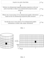
- FIG. 1 is a schematic diagram of a point cloud encoding method based on two-dimensional regularized plane projection according to an embodiment of the present invention. The method includes the following steps.
- the raw point cloud data generally includes a set of three-dimensional spatial points, and each spatial point records its own geometric position information, as well as additional attribute information such as color, reflectivity, and normal line.
- the geometric position information of a point cloud is generally represented using the Cartesian coordinate system, namely, X, Y, and Z coordinates of points.
- the raw point cloud data may be obtained by using a 3D scanning device such as a laser radar, and may also be obtained from common datasets provided by various platforms.
- the geometric position information of the acquired raw point cloud data is represented based on the Cartesian coordinate system. It should be noted that a representation method of the geometric position information of the raw point cloud data is not limited to Cartesian coordinates.
- preprocessing may also be performed on the raw point cloud data, for example, voxelization processing, to facilitate subsequent encoding.
- the two-dimensional projection plane structure is initialized.
- Regularization parameters need to be used in initializing the two-dimensional regularized projection plane structure of a point cloud.
- the regularization parameters are finely measured by the manufacturer and provided for consumers as one of necessary data, for example, an acquisition range of a laser radar, sampled angular resolution ⁇ ⁇ or number of sampled points for horizontal azimuth, as well as a distance correction factor of each laser scanner, information on offsets of a laser scanner along the vertical and horizontal directions V o and H o , and information on offsets of a laser scanner along the pitch angle and horizontal azimuth angle ⁇ 0 and ⁇ .
- the regularization parameters are not limited to the above-mentioned parameters, which may be given calibration parameters of the laser radar, or may be obtained by such means as estimation optimization and data fitting if the calibration parameters of the laser radar are not given.
- the two-dimensional regularized projection plane structure of a point cloud is a data structure containing M rows of and N columns of pixels. After projection, points in a three-dimensional point cloud correspond to pixels in the data structure.
- a pixel ( i , j ) in the data structure can be associated with a cylindrical coordinate component ( ⁇ , ⁇ ).
- FIG. 2 is a schematic diagram of a mapping between cylindrical coordinates of a point and a pixel in a two-dimensional projection plane according to an embodiment of the present invention.
- mapping is not limited to the mapping between pixels and cylindrical coordinates.
- mapping between the raw point cloud data and the two-dimensional projection plane structure is determined, so as to project the raw point cloud data onto the two-dimensional projection plane structure.
- a position of the raw point cloud in the two-dimensional projection plane structure is determined point by point, so as to map originally discretely distributed point clouds in the Cartesian coordinate system to the uniformly distributed two-dimensional regularized projection plane structure.
- a corresponding pixel is determined in the two-dimensional projection plane structure for each point in the raw point cloud. For example, a pixel with the smallest spatial distance from the projected position of a point in the two-dimensional plane can be selected as a corresponding pixel of the point.
- FIG. 3 is a schematic diagram of a two-dimensional projection plane structure of a point cloud according to an embodiment of the present invention, where each point in the raw point cloud data is mapped to a corresponding pixel in this structure.
- a plurality of points in the point cloud may correspond to a same pixel in the two-dimensional projection plane structure.
- these spatial points can be projected to different pixels during projection. For example, during projection of a specified point, if its corresponding pixel already corresponds to a point, the specified point is projected to an empty pixel adjacent to the pixel.
- the number of corresponding points in each pixel should also be encoded and information on each of the corresponding points in the pixel should be encoded based on the number of corresponding points.
- the one or more pieces of two-dimensional graphic information includes a coordinate conversion error information graph.
- the coordinate conversion error information graph is used to represent a residual between a spatial position obtained by back projection of each occupied pixel in the two-dimensional regularized projection plane structure and a spatial position of a raw point corresponding to the pixel.
- the following method can be used to calculate a coordinate conversion error of a pixel. Assuming that the current pixel is ( i , j ) and Cartesian coordinates of its corresponding point is ( x,y,z ), regularization parameters and the following formula can be used to convert the pixel back to the Cartesian coordinate system and obtain the corresponding Cartesian coordinates ( xl,yl,zl ).
- each occupied pixel in the two-dimensional regularized projection plane structure has a coordinate conversion error, and therefore a coordinate conversion error information graph corresponding to the point cloud is obtained.
- the encoding the one or more pieces of two-dimensional graphic information to obtain bit stream information includes: encoding the coordinate conversion error information graph to obtain a coordinate conversion error information bit stream. Specifically, the coordinate conversion error information graph needs to be predicted to obtain a prediction residual of the coordinate conversion error information, and then the prediction residual is encoded.
- pixels in the coordinate conversion error information graph may be predicted based on a placeholder information graph, a depth information graph, a projection residual information graph, and reconstructed coordinate conversion error information of encoded and decoded pixels to obtain a prediction residual.
- the placeholder information graph is used to identify whether a pixel in the two-dimensional regularized projection plane structure is occupied, that is, whether each pixel corresponds to a point in the point cloud. If occupied, the pixel is non-empty; otherwise, the pixel is empty. Therefore, the placeholder information graph can be obtained based on the two-dimensional projection plane structure of the point cloud.
- the depth information graph is used to represent distance between the corresponding point of each occupied pixel in the two-dimensional regularized projection plane structure and the coordinate origin.
- the cylindrical coordinate component r of the corresponding point of the pixel can be used as depth of the pixel. Based on this, each occupied pixel in the two-dimensional regularized projection plane structure has a depth value, and therefore the depth information graph is obtained.
- the projection residual information graph is used to represent a residual between a corresponding position and an actual projection position of each occupied pixel in the two-dimensional regularized projection plane structure. Based on this, each occupied pixel in the two-dimensional regularized projection plane structure has a projection residual, and therefore the projection residual information graph is obtained.
- the placeholder information graph, the depth information graph, and the projection residual information graph can all be directly obtained from the two-dimensional regularized projection plane structure.
- FIG. 4 is a block diagram of encoding a coordinate conversion error information graph according to an embodiment of the present invention, which specifically includes the following.
- the coordinate conversion error of the current pixel can be predicted based on the placeholder information graph, the depth information graph, the projection residual information graph, and the reconstructed coordinate conversion error information of encoded and decoded pixels. Details are as follows.
- each pixel in the coordinate conversion error information graph may be traversed by using a Z-scan method.
- a simple relationship can be established to select a reference pixel, from the encoded and decoded non-empty pixels in the adjacent area of the current non-empty pixel, which is close to the current pixel in terms of depth information and projection residual information.
- FIG. 5 is a schematic diagram of predicting a coordinate conversion error according to an embodiment of the present invention.
- ⁇ represents the current pixel
- ⁇ represents the reference pixel in the adjacent area
- (S) represents an empty pixel that has been encoded and decoded and not been occupied.
- the placeholder information graph is used to determine occupancy status of encoded and decoded pixels in an area adjacent to the current pixel, that is, within the dashed-line box, non-empty pixels in the area are identified, and then these encoded and decoded non-empty pixels can be used to simply establish a relationship between the depth information and a reconstructed coordinate conversion error. For example, the following relationship may be established: if two pixels have similar depth information, their coordinate conversion errors are similar. Likewise, these encoded and decoded non-empty pixels may also be used to simply establish a relationship between the projection residual information and the reconstructed coordinate conversion error.
- the following relationship may be established: if two pixels have similar projection residual, their coordinate conversion errors are similar.
- pixels that are similar to the current pixel in terms of the depth information and the projection residual information can be selected, from these encoded and decoded non-empty pixels, as the reference pixels, and an average of reconstructed coordinate conversion error information of these reference pixels is calculated and used as a predicted value ( ⁇ x _ pred, ⁇ y_pred, ⁇ z_pred ) of the coordinate conversion error information of the current pixel.
- pixels in the coordinate conversion error information graph may also be predicted based on part of information graphs among the placeholder information graph, the depth information graph, and the projection residual information graph to obtain a prediction residual of a coordinate conversion error.
- the detailed process is not described herein.
- prediction is performed on the coordinate conversion error information graph by using the placeholder information graph, the depth information graph, and the projection residual information graph. This improves the encoding efficiency.
- a conventional encoding method may be used: predicting pixels in the coordinate conversion error information graph directly based on reconstructed coordinate conversion error information of encoded and decoded pixels to obtain the prediction residual.
- a rate-distortion optimization model may also be used to select an optimal prediction mode from a number of preset prediction modes for predicting the pixels in the coordinate conversion error information graph, to obtain the prediction residual.
- the following six prediction modes may be set.
- the rate-distortion optimization model is used to select an optimal mode for prediction to obtain the prediction residual.
- the prediction residual needs to be encoded. It should be noted that lossy encoding of the coordinate conversion information graph requires the prediction residual of the coordinate conversion error information to be quantized before being encoded. Lossless encoding of the coordinate conversion information graph does not require quantization of the prediction residual.
- a context-based entropy coding method is used for implementation.
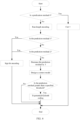
- the entropy coding process illustrated in FIG. 6 can be used to encode the prediction residual, where Cnt represents the number of consecutive prediction residual components that are zero.
- the detailed encoding process is as follows:
- the coordinate conversion error information graph may also be encoded by image ⁇ video compression.
- the applicable encoding schemes herein include but are not limited to JPEG, JPEG2000, HEIF, H.264 ⁇ AVC, and H.265 ⁇ HEVC.
- encoding may be performed on other information graphs obtained based on the two-dimensional projection plane structure, such as the placeholder information graph, the depth information graph, the projection residual information graph, and an attribute information graph, to obtain corresponding bit stream information.
- a point cloud in a three-dimension space is projected into a corresponding two-dimensional regularized projection plane structure, and the point cloud is corrected through regularization in a vertical direction and a horizontal direction.
- a strong correlation representation of the point cloud on the two-dimensional projection plane structure is obtained. This avoids sparsity in a three-dimensional representation structure and highlights spatial correlation of the point cloud.
- the spatial correlation of the point cloud can be fully utilized to reduce spatial redundancy. This further improves the encoding efficiency of the point cloud.
- FIG. 7 is a schematic structural diagram of a point cloud encoding apparatus based on two-dimensional regularized plane projection according to an embodiment of the present invention.
- the apparatus includes:
- the encoding apparatus provided in this embodiment can implement the encoding method described in embodiment 1. The detailed process is not described herein again.
- FIG. 8 is a schematic diagram of a point cloud decoding method based on two-dimensional regularized plane projection according to an embodiment of the present invention. The method includes the following steps.
- a decoding end acquires compressed bit stream information, and uses a corresponding existing entropy decoding technology to decode the bit stream information accordingly to obtain the parsed data.
- the prediction residual obtained by parsing needs to be dequantized herein.
- step 2 may include: reconstructing a coordinate conversion error information graph based on prediction residual of the coordinate conversion error information graph in the parsed data to obtain a reconstructed coordinate conversion error information graph.
- the one or more pieces of two-dimensional graphic information may include the coordinate conversion error information graph, meaning that the coordinate conversion error information graph has been encoded.
- bit stream information at the decoding end also includes a coordinate conversion error information bit stream. More specifically, the parsed data obtained by decoding the bit stream information includes the prediction residual of the coordinate conversion error information.
- the pixels in the coordinate conversion error information graph are traversed according to a specified scanning order and the coordinate conversion error information of the non-empty pixels therein is encoded. Therefore, the prediction residual of the coordinate conversion error information of the pixels obtained by the decoding end also follows this order, and the decoding end can obtain resolution of the coordinate conversion error information graph by using regularization parameters. For details, refer to S2 of embodiment 1, in which the two-dimensional projection plane structure is initialized. Therefore, the decoding end can obtain a position of a current to-be-reconstructed pixel in the two-dimensional graph based on the resolution of the coordinate conversion error information graph and the placeholder information graph.
- FIG. 9 is a block diagram of decoding a coordinate conversion error information graph according to an embodiment of the present invention.
- Coordinate conversion error information of the current to-be-reconstructed pixel is predicted based on the placeholder information graph, a depth information graph, a projection residual information graph, and reconstructed coordinate conversion error information of encoded and decoded pixels. This is the same as the prediction method used at the encoding end.
- the placeholder information graph is used to determine occupancy status of encoded and decoded pixels in an area adjacent to the current to-be-reconstructed pixel, that is, within the dashed-line box, and then non-empty pixels in the area are identified.
- the relationship, which is established by the encoding end, between the depth information and reconstructed coordinate conversion error information of these encoded and decoded non-empty pixels is used: if two pixels have similar depth information, their coordinate conversion errors are similar.
- the relationship, which is established by the encoding end, between the projection residual information and the reconstructed coordinate conversion error is also used: if two pixels have similar projection residual information, their coordinate conversion errors are similar.
- pixels that are similar to the current pixel in terms of depth information and projection residual information can be selected, from these encoded and decoded non-empty pixels, as the reference pixels, and an average of reconstructed coordinate conversion error information of these reference pixels is calculated and used as a predicted value of the coordinate conversion error information of the current pixel.
- the coordinate conversion error information of the current pixel is reconstructed based on the predicted value obtained and the prediction residual obtained by parsing.
- a reconstructed coordinate conversion error information graph is obtained.
- Pixels in the reconstructed two-dimensional projection plane structure are traversed according to a specified scanning order, so that the coordinate conversion error information of each non-empty pixel can be obtained.
- the current pixel ( i,j ) is non-empty and its coordinate conversion error is ( ⁇ x , ⁇ y , ⁇ z )
- other information such as depth information is used to reconstruct a spatial point ( x,y,z ) corresponding to the pixel.
- a position corresponding to the current pixel ( i , j ) may be represented as ( ⁇ j , i ).
- Regularization parameters and other information such as the depth information r can be used to reconstruct the spatial point ( x , y,z ) corresponding to the current pixel.
- a corresponding spatial point can be reconstructed for each non-empty pixel in the two-dimensional projection structure based on the foregoing calculations, so as to obtain a reconstructed point cloud.
- FIG. 10 is a schematic structural diagram of a point cloud decoding apparatus based on two-dimensional regularized plane projection according to an embodiment of the present invention.
- the apparatus includes:
- the decoding apparatus provided in this embodiment can implement the decoding method described in embodiment 5. The detailed process is not described herein again.
Landscapes
- Engineering & Computer Science (AREA)
- Multimedia (AREA)
- Signal Processing (AREA)
- Physics & Mathematics (AREA)
- General Physics & Mathematics (AREA)
- Theoretical Computer Science (AREA)
- Image Processing (AREA)
- Image Generation (AREA)
Abstract
Description
- This application claims priority to
Chinese Patent Application No. 202110171969.5, filed with the China National Intellectual Property Administration on February 8, 2021 - The present invention pertains to the field of codec technologies, and specifically, to a point cloud encoding/decoding method apparatus based on two-dimensional regularized plane projection.
- With the improvement of hardware processing capabilities and the rapid development of computer vision, three-dimensional point clouds have been a new generation of immersive multimedia following audio, image, and video, and are widely used in virtual reality, augmented reality, autonomous driving, environmental modeling, and the like. However, a three-dimensional point cloud generally has a large amount of data, which hinders transmission and storage of point cloud data. Therefore, research on an efficient point cloud encoding and decoding technology is of great significance.
- In an existing geometry-based point cloud compression coding (G-PCC, Geometry-based Point Cloud Compression) framework, geometric information and attribute information of a point cloud are encoded separately. At present, geometric codec of G-PCC can be classified into octree-based geometric codec and prediction tree-based geometric codec.
- For octree-based geometric codec: geometric information of a point cloud is first preprocessed at the encoding end. This involves coordinate conversion and voxelization of the point cloud. Then, tree division (octree/quadtree/binary tree) is performed constantly in order of breadth-first search on a bounding box where the point cloud is located. Finally, a placeholder code of each node is encoded and the number of points contained in each leaf node is encoded to generate a binary bit stream. At the decoding end, constant parsing is first performed in order of breadth-first search to obtain the placeholder code of each node. Then, tree division is performed constantly and sequentially until a unit cube of 1x1x1 is obtained. Finally, the number of points contained in each leaf node is obtained by parsing, and reconstructed geometric information of the point cloud is obtained.
- For prediction tree-based geometric codec: sorting is performed on an input point cloud at the encoding end. Then, a prediction tree structure is established. Each point is classified to a laser scanner it belongs to, and the prediction tree structure is established based on different laser scanners. Next, each node in the prediction tree is traversed. Different prediction modes are selected to predict geometric information of a node to obtain a prediction residual, and a quantization parameter is used to quantify the prediction residual. Finally, the prediction tree structure, the quantization parameter, the prediction residual of the geometry information of the node, and the like are encoded to generate a binary bit stream. At the decoding end, the bit stream is parsed, and the prediction tree structure is reconstructed. Then, the prediction residual is dequantized using geometric information prediction residual of each node obtained by parsing and the quantization parameter. Finally, reconstructed geometric information of each node is retrieved. In this way, the geometric information of the point cloud is reconstructed.
- However, a point cloud has a high spatial sparsity. Therefore, for a point cloud encoding technology using an octree structure, empty nodes obtained by division takes up a high proportion, and spatial correlation of the point cloud cannot be fully reflected. This hinders prediction and entropy coding of the point cloud. For the point cloud codec technology based on the prediction tree, some parameters of a laser radar device are used to establish a tree structure. On this basis, the tree structure is used for predictive coding, but this tree structure does not fully reflect the spatial correlation of a point cloud and therefore hinders prediction and entropy coding of the point cloud. As a result, both the foregoing two point cloud codec technologies have a problem of low encoding efficiency.
- To solve the foregoing problem in the prior art, the present invention provides a point cloud encoding/decoding method and apparatus based on two-dimensional regularized plane projection. In the present invention, the technical problem is solved by using the following technical solution:
- A point cloud encoding method based on two-dimensional regularized plane projection, including:
- acquiring raw point cloud data;
- performing two-dimensional regularized plane projection on the raw point cloud data to obtain a two-dimensional projection plane structure;
- obtaining one or more pieces of two-dimensional graphic information based on the two-dimensional projection plane structure; and
- encoding the one or more pieces of two-dimensional graphic information to obtain bit stream information.
- In an embodiment of the present invention, the one or more pieces of two-dimensional graphic information includes a coordinate conversion error information graph.
- In an embodiment of the present invention, the encoding the one or more pieces of two-dimensional graphic information to obtain bit stream information includes: encoding the coordinate conversion error information graph to obtain a coordinate conversion error information bit stream.
- In an embodiment of the present invention, the encoding the coordinate conversion error information graph to obtain a coordinate conversion error information bit stream includes:
- predicting pixels in the coordinate conversion error information graph based on a placeholder information graph, a depth information graph, and a projection residual information graph to obtain a prediction residual of a coordinate conversion error; or
- predicting pixels in the coordinate conversion error information graph based on reconstructed coordinate conversion error information of encoded and decoded pixels to obtain a prediction residual of a coordinate conversion error; and
- encoding the prediction residual of the coordinate conversion error to obtain the coordinate conversion error information bit stream.
- In an embodiment of the present invention, the predicting pixels in the coordinate conversion error information graph based on a placeholder information graph, a depth information graph, and a projection residual information graph to obtain a prediction residual of a coordinate conversion error includes:
- traversing the pixels in the coordinate conversion error information graph according to a specified scanning order, and identifying encoded and decoded non-empty pixels in an area adjacent to a current non-empty pixel based on the placeholder information graph;
- establishing a relationship between depth information and coordinate conversion error information by using the encoded and decoded non-empty pixels, and establishing a relationship between projection residual information and coordinate conversion error information by using the encoded and decoded non-empty pixels;
- estimating coordinate conversion error information corresponding to a current pixel based on the relationship between depth information and coordinate conversion error information and the relationship between projection residual information and coordinate conversion error information, to obtain an estimated value of the coordinate conversion error of the current pixel; and
- using the estimated value as a predicted value of the coordinate conversion error of the current pixel to obtain a prediction residual of the coordinate conversion error of the current pixel.
- In an embodiment of the present invention, the encoding the coordinate conversion error information graph to obtain a coordinate conversion error information bit stream further includes:
- predicting pixels in the coordinate conversion error information graph based on part of information graphs among a placeholder information graph, a depth information graph, and a projection residual information graph to obtain a prediction residual of a coordinate conversion error; and
- encoding the prediction residual of the coordinate conversion error to obtain the coordinate conversion error information bit stream.
- Another embodiment of the present invention further provides a point cloud encoding apparatus based on two-dimensional regularized plane projection. The apparatus includes:
- a first data acquisition module, configured to acquire raw point cloud data;
- a projection module, configured to perform two-dimensional regularized plane projection on the raw point cloud data to obtain a two-dimensional projection plane structure;
- a data processing module, configured to obtain one or more pieces of two-dimensional graphic information based on the two-dimensional projection plane structure; and
- an encoding module, configured to encode the one or more pieces of two-dimensional graphic information to obtain bit stream information.
- Still another embodiment of the present invention further provides a point cloud decoding method based on two-dimensional regularized plane projection. The method includes:
- acquiring and decoding bit stream information to obtain parsed data;
- reconstructing one or more pieces of two-dimensional graphic information based on the parsed data;
- obtaining a two-dimensional projection plane structure based on the one or more pieces of two-dimensional graphic information; and
- reconstructing a point cloud by using the two-dimensional projection plane structure.
- In an embodiment of the present invention, the reconstructing one or more pieces of two-dimensional graphic information based on the parsed data includes:
reconstructing a coordinate conversion error information graph based on a prediction residual of the coordinate conversion error information graph in the parsed data to obtain a reconstructed coordinate conversion error information graph. - Still yet another embodiment of the present invention further provides a point cloud decoding apparatus based on two-dimensional regularized plane projection. The apparatus includes:
- a second data acquisition module, configured to acquire and decode bit stream information to obtain parsed data;
- a first reconstruction module, configured to reconstruct one or more pieces of two-dimensional graphic information based on the parsed data;
- a second reconstruction module, configured to obtain a two-dimensional projection plane structure based on the one or more pieces of two-dimensional graphic information; and
- a point cloud reconstruction module, configured to reconstruct a point cloud by using the two-dimensional projection plane structure.
- Beneficial effects of the present invention are as follows:
- 1. In the present invention, a point cloud in a three-dimension space is projected into a corresponding two-dimensional regularized projection plane structure, and the point cloud is corrected through regularization in a vertical direction and a horizontal direction. In this way, a strong correlation representation of the point cloud on the two-dimensional projection plane structure is obtained. This avoids sparsity in a three-dimensional representation structure and highlights spatial correlation of the point cloud. During subsequent encoding of a coordinate conversion error information graph obtained from the two-dimensional regularized projection plane structure, the spatial correlation of the point cloud can be fully utilized to reduce spatial redundancy. This further improves the encoding efficiency of the point cloud.
- 2. In the present invention, predictive coding is performed on a coordinate conversion error information graph by using a placeholder information graph, a depth information graph, and a projection residual information graph. This improves the encoding efficiency.
- The following further describes the present invention in detail with reference to the accompanying drawings and embodiments.
-
-
FIG. 1 is a schematic diagram of a point cloud encoding method based on two-dimensional regularized plane projection according to an embodiment of the present invention; -
FIG. 2 is a schematic diagram of a mapping between cylindrical coordinates of a point and a pixel in a two-dimensional projection plane according to an embodiment of the present invention; -
FIG. 3 is a schematic diagram of a two-dimensional projection plane structure of a point cloud according to an embodiment of the present invention; -
FIG. 4 is a block diagram of encoding a coordinate conversion error information graph according to an embodiment of the present invention; -
FIG. 5 is a schematic diagram of predicting a coordinate conversion error according to an embodiment of the present invention; -
FIG. 6 is a flowchart of entropy coding of a prediction residual of a coordinate conversion error according to an embodiment of the present invention; -
FIG. 7 is a schematic structural diagram of a point cloud encoding apparatus based on two-dimensional regularized plane projection according to an embodiment of the present invention; -
FIG. 8 is a schematic diagram of a point cloud decoding method based on two-dimensional regularized plane projection according to an embodiment of the present invention; -
FIG. 9 is a block diagram of decoding a coordinate conversion error information graph according to an embodiment of the present invention; and -
FIG. 10 is a schematic structural diagram of a point cloud decoding apparatus based on two-dimensional regularized plane projection according to an embodiment of the present invention. - The following further describes the present invention in detail with reference to specific embodiments, but the embodiments of the present invention are not limited hereto.
- Refer to
FIG. 1. FIG. 1 is a schematic diagram of a point cloud encoding method based on two-dimensional regularized plane projection according to an embodiment of the present invention. The method includes the following steps. - S1. Acquire raw point cloud data.
- Specifically, the raw point cloud data generally includes a set of three-dimensional spatial points, and each spatial point records its own geometric position information, as well as additional attribute information such as color, reflectivity, and normal line. The geometric position information of a point cloud is generally represented using the Cartesian coordinate system, namely, X, Y, and Z coordinates of points. The raw point cloud data may be obtained by using a 3D scanning device such as a laser radar, and may also be obtained from common datasets provided by various platforms. In this embodiment, the geometric position information of the acquired raw point cloud data is represented based on the Cartesian coordinate system. It should be noted that a representation method of the geometric position information of the raw point cloud data is not limited to Cartesian coordinates.
- S2. Perform two-dimensional regularized plane projection on the raw point cloud data to obtain a two-dimensional projection plane structure.
- Specifically, in this embodiment, before two-dimensional regularized plane projection is performed on a raw point cloud, preprocessing may also be performed on the raw point cloud data, for example, voxelization processing, to facilitate subsequent encoding.
- First, the two-dimensional projection plane structure is initialized.
- Regularization parameters need to be used in initializing the two-dimensional regularized projection plane structure of a point cloud. Generally, the regularization parameters are finely measured by the manufacturer and provided for consumers as one of necessary data, for example, an acquisition range of a laser radar, sampled angular resolution Δϕ or number of sampled points for horizontal azimuth, as well as a distance correction factor of each laser scanner, information on offsets of a laser scanner along the vertical and horizontal directions Vo and Ho , and information on offsets of a laser scanner along the pitch angle and horizontal azimuth angle θ 0 and α.
- It should be noted that the regularization parameters are not limited to the above-mentioned parameters, which may be given calibration parameters of the laser radar, or may be obtained by such means as estimation optimization and data fitting if the calibration parameters of the laser radar are not given.
- The two-dimensional regularized projection plane structure of a point cloud is a data structure containing M rows of and N columns of pixels. After projection, points in a three-dimensional point cloud correspond to pixels in the data structure. In addition, a pixel (i,j) in the data structure can be associated with a cylindrical coordinate component (θ,φ). For example, a pixel (i,j) corresponding to cylindrical coordinates (r,θ,φ) can be found using the following formula:


- Specifically, refer to
FIG. 2. FIG. 2 is a schematic diagram of a mapping between cylindrical coordinates of a point and a pixel in a two-dimensional projection plane according to an embodiment of the present invention. - It should be noted that such a mapping is not limited to the mapping between pixels and cylindrical coordinates.
- Further, resolution of the two-dimensional regularized projection plane may be obtained from the regularization parameters. For example, if the resolution of the two-dimensional regularized projection plane is M × N, the number of laser scanners in the regularization parameters can be used to initialize M, and the sampled angular resolution for horizontal azimuth Δϕ (or the number of sampled points of the laser scanner) is used to initialize N. For example, the following formula can be used to eventually initialize the two-dimensional projection plane structure and obtain a plane structure containing M × N pixels.


- Second, the mapping between the raw point cloud data and the two-dimensional projection plane structure is determined, so as to project the raw point cloud data onto the two-dimensional projection plane structure.
- In this part, a position of the raw point cloud in the two-dimensional projection plane structure is determined point by point, so as to map originally discretely distributed point clouds in the Cartesian coordinate system to the uniformly distributed two-dimensional regularized projection plane structure. Specifically, a corresponding pixel is determined in the two-dimensional projection plane structure for each point in the raw point cloud. For example, a pixel with the smallest spatial distance from the projected position of a point in the two-dimensional plane can be selected as a corresponding pixel of the point.
- If two-dimensional projection is performed in the cylindrical coordinate system, a specific process of determining pixels corresponding to a raw point cloud is as follows.
- a. Determine a cylindrical coordinate component r of a current point in the raw point cloud data. Specifically, calculation is performed using the following formula:

- b. Determine a search area for the current point in the two-dimensional projection plane structure. Specifically, the entire two-dimensional projection plane structure may be directly selected as the search area. Further, to reduce the amount of computation, the search area for the corresponding pixel in the two-dimensional projection plane structure may also be determined based on cylindrical coordinate components of a pitch angle θ and an azimuth angle φ of the current point, so as to reduce the search area.
- c. After the search area is determined, for each pixel (i,j) therein, calculate a position (xl,yl,zl) of a current pixel in the Cartesian coordinate system by using the regularization parameters, namely, calibration parameters of the i-th laser scanner of the laser radar θ 0, Vo, Ho , and α. The specific calculation formulas are as follows:





- d. After the position (xl,yl,zl) of the current pixel in the Cartesian coordinate system is obtained, calculate a spatial distance between the current pixel and the current point (x,y,z) and use it as an error Err, namely:

If the error Err is smaller than a current minimum error minErr, the error Err is used to update the minimum error minErr, and i and j corresponding to the current pixel are used to update i and j of a pixel corresponding to the current point. If the error Err is greater than the minimum error minErr, the foregoing update process is not performed. - e. When all pixels in the search area are traversed, the corresponding pixel (i,j) of the current point in the two-dimensional projection plane structure can be determined.
- When the foregoing operations are completed on all points in the raw point cloud, the two-dimensional regularized plane projection of the point cloud is completed. Specifically, refer to
FIG. 3. FIG. 3 is a schematic diagram of a two-dimensional projection plane structure of a point cloud according to an embodiment of the present invention, where each point in the raw point cloud data is mapped to a corresponding pixel in this structure. - It should be noted that during the two-dimensional regularized plane projection of a point cloud, a plurality of points in the point cloud may correspond to a same pixel in the two-dimensional projection plane structure. To avoid this situation, these spatial points can be projected to different pixels during projection. For example, during projection of a specified point, if its corresponding pixel already corresponds to a point, the specified point is projected to an empty pixel adjacent to the pixel. In addition, if a plurality of points in a point cloud have been projected to a same pixel in the two-dimensional projection plane structure, during encoding based on the two-dimensional projection plane structure, the number of corresponding points in each pixel should also be encoded and information on each of the corresponding points in the pixel should be encoded based on the number of corresponding points.
- S3. Obtain one or more pieces of two-dimensional graphic information based on the two-dimensional projection plane structure.
- In this embodiment, the one or more pieces of two-dimensional graphic information includes a coordinate conversion error information graph.
- Specifically, the coordinate conversion error information graph is used to represent a residual between a spatial position obtained by back projection of each occupied pixel in the two-dimensional regularized projection plane structure and a spatial position of a raw point corresponding to the pixel.
- For example, the following method can be used to calculate a coordinate conversion error of a pixel. Assuming that the current pixel is (i,j) and Cartesian coordinates of its corresponding point is (x,y,z), regularization parameters and the following formula can be used to convert the pixel back to the Cartesian coordinate system and obtain the corresponding Cartesian coordinates (xl,yl,zl).


- Next, the coordinate conversion error (Δx,Δy,Δz) of the current pixel can be calculated using the following formula:


- According to the foregoing calculations, each occupied pixel in the two-dimensional regularized projection plane structure has a coordinate conversion error, and therefore a coordinate conversion error information graph corresponding to the point cloud is obtained.
- S4. Encode the one or more pieces of two-dimensional graphic information to obtain bit stream information.
- Accordingly, the encoding the one or more pieces of two-dimensional graphic information to obtain bit stream information includes: encoding the coordinate conversion error information graph to obtain a coordinate conversion error information bit stream. Specifically, the coordinate conversion error information graph needs to be predicted to obtain a prediction residual of the coordinate conversion error information, and then the prediction residual is encoded.
- In this embodiment, pixels in the coordinate conversion error information graph may be predicted based on a placeholder information graph, a depth information graph, a projection residual information graph, and reconstructed coordinate conversion error information of encoded and decoded pixels to obtain a prediction residual.
- The placeholder information graph is used to identify whether a pixel in the two-dimensional regularized projection plane structure is occupied, that is, whether each pixel corresponds to a point in the point cloud. If occupied, the pixel is non-empty; otherwise, the pixel is empty. Therefore, the placeholder information graph can be obtained based on the two-dimensional projection plane structure of the point cloud.
- The depth information graph is used to represent distance between the corresponding point of each occupied pixel in the two-dimensional regularized projection plane structure and the coordinate origin. For example, the cylindrical coordinate component r of the corresponding point of the pixel can be used as depth of the pixel. Based on this, each occupied pixel in the two-dimensional regularized projection plane structure has a depth value, and therefore the depth information graph is obtained.
- The projection residual information graph is used to represent a residual between a corresponding position and an actual projection position of each occupied pixel in the two-dimensional regularized projection plane structure. Based on this, each occupied pixel in the two-dimensional regularized projection plane structure has a projection residual, and therefore the projection residual information graph is obtained.
- The placeholder information graph, the depth information graph, and the projection residual information graph can all be directly obtained from the two-dimensional regularized projection plane structure.
- Refer to
FIG. 4. FIG. 4 is a block diagram of encoding a coordinate conversion error information graph according to an embodiment of the present invention, which specifically includes the following. - 41) Predict the coordinate conversion error of a pixel.
- In this embodiment, the coordinate conversion error of the current pixel can be predicted based on the placeholder information graph, the depth information graph, the projection residual information graph, and the reconstructed coordinate conversion error information of encoded and decoded pixels. Details are as follows.
- 41a) Traverse each pixel in the coordinate conversion error information graph according to a specified scanning order, and identify encoded and decoded non-empty pixels in an area adjacent to a current non-empty pixel based on the placeholder information graph.
- For example, in this embodiment, each pixel in the coordinate conversion error information graph may be traversed by using a Z-scan method.
- 41b) Establish a relationship between depth information and reconstructed coordinate conversion error information by using the encoded and decoded non-empty pixels, and establish a relationship between projection residual information and the reconstructed coordinate conversion error information by using the encoded and decoded non-empty pixels.
- For example, a simple relationship can be established to select a reference pixel, from the encoded and decoded non-empty pixels in the adjacent area of the current non-empty pixel, which is close to the current pixel in terms of depth information and projection residual information.
- Specifically, refer to
FIG. 5. FIG. 5 is a schematic diagram of predicting a coordinate conversion error according to an embodiment of the present invention. ☆ represents the current pixel, ○ represents the reference pixel in the adjacent area,represents an adjacent-area pixel that differs greatly from the current pixel in the depth information, represents an adjacent-area pixel that differs greatly from the current pixel in the projection residual information, and (S) represents an empty pixel that has been encoded and decoded and not been occupied.
- During prediction of the coordinate conversion error of the current pixel, the placeholder information graph is used to determine occupancy status of encoded and decoded pixels in an area adjacent to the current pixel, that is, within the dashed-line box, non-empty pixels in the area are identified, and then these encoded and decoded non-empty pixels can be used to simply establish a relationship between the depth information and a reconstructed coordinate conversion error. For example, the following relationship may be established: if two pixels have similar depth information, their coordinate conversion errors are similar. Likewise, these encoded and decoded non-empty pixels may also be used to simply establish a relationship between the projection residual information and the reconstructed coordinate conversion error. For example, the following relationship may be established: if two pixels have similar projection residual, their coordinate conversion errors are similar. In this case, pixels that are similar to the current pixel in terms of the depth information and the projection residual information can be selected, from these encoded and decoded non-empty pixels, as the reference pixels, and an average of reconstructed coordinate conversion error information of these reference pixels is calculated and used as a predicted value (Δx_pred,Δy_pred,Δz_pred) of the coordinate conversion error information of the current pixel. The specific calculation formulas are as follows:


- In this embodiment, pixels in the coordinate conversion error information graph may also be predicted based on part of information graphs among the placeholder information graph, the depth information graph, and the projection residual information graph to obtain a prediction residual of a coordinate conversion error. The detailed process is not described herein.
- In the present invention, during encoding of the coordinate conversion error information, prediction is performed on the coordinate conversion error information graph by using the placeholder information graph, the depth information graph, and the projection residual information graph. This improves the encoding efficiency.
- In another embodiment of the present invention, a conventional encoding method may be used: predicting pixels in the coordinate conversion error information graph directly based on reconstructed coordinate conversion error information of encoded and decoded pixels to obtain the prediction residual.
- In addition, a rate-distortion optimization model may also be used to select an optimal prediction mode from a number of preset prediction modes for predicting the pixels in the coordinate conversion error information graph, to obtain the prediction residual.
- For example, the following six prediction modes may be set.
- Mode 0: direct mode, performing direct compression without prediction;
- Mode 1: leftward prediction, using non-empty pixels on the left side as the reference pixels;
- Mode 2: upward prediction, using non-empty pixels on the upward side as the reference pixels;
- Mode 3: upper-left prediction, using non-empty pixels on the upper left side as the reference pixels;
- Mode 4: upper-right prediction, using non-empty pixels on the upper right side as the reference pixels; and
- Mode 5: using non-empty pixels on the left side, upward side, upper left side, and upper right side as the reference pixels.
- The rate-distortion optimization model is used to select an optimal mode for prediction to obtain the prediction residual.
- 42) Encode the prediction residual to obtain the coordinate conversion error information bit stream.
- After the coordinate conversion error information is predicted, the prediction residual needs to be encoded. It should be noted that lossy encoding of the coordinate conversion information graph requires the prediction residual of the coordinate conversion error information to be quantized before being encoded. Lossless encoding of the coordinate conversion information graph does not require quantization of the prediction residual.
- Specifically, in this embodiment, a context-based entropy coding method is used for implementation. For example, the entropy coding process illustrated in
FIG. 6 can be used to encode the prediction residual, where Cnt represents the number of consecutive prediction residual components that are zero. The detailed encoding process is as follows: - a. First determine whether the prediction residual of the coordinate conversion error of the current pixel is 0. If it is 0, Cnt is increased by 1 and no encoding is performed subsequently.
- b. Otherwise, encode Cnt and determine whether the prediction residual of the coordinate conversion error of the current pixel is 1. If it is 1, the
identifier 1 is encoded and no encoding is performed subsequently. - c. Otherwise, determine whether the prediction residual of the coordinate conversion error of the current pixel is 2. If it is 2, the
identifier 2 is encoded and no encoding is performed subsequently. - d. Otherwise, decrease the prediction residual of the coordinate conversion error of the current pixel by 3 and determine whether the prediction residual is greater than a specified threshold. If it is smaller than the specified threshold, a context model is designed for the prediction residual; otherwise, encoding is performed in the following manner:
- designing a context for encoding prediction residual information smaller than the threshold; and
- performing exponential-Golomb coding on prediction residual information greater than the threshold.
- In addition, in another embodiment of the present invention, the coordinate conversion error information graph may also be encoded by image\video compression. The applicable encoding schemes herein include but are not limited to JPEG, JPEG2000, HEIF, H.264\AVC, and H.265\HEVC.
- In another embodiment of the present invention, encoding may be performed on other information graphs obtained based on the two-dimensional projection plane structure, such as the placeholder information graph, the depth information graph, the projection residual information graph, and an attribute information graph, to obtain corresponding bit stream information.
- In the present invention, a point cloud in a three-dimension space is projected into a corresponding two-dimensional regularized projection plane structure, and the point cloud is corrected through regularization in a vertical direction and a horizontal direction. In this way, a strong correlation representation of the point cloud on the two-dimensional projection plane structure is obtained. This avoids sparsity in a three-dimensional representation structure and highlights spatial correlation of the point cloud. During subsequent encoding of a coordinate conversion error information graph obtained from the two-dimensional regularized projection plane structure, the spatial correlation of the point cloud can be fully utilized to reduce spatial redundancy. This further improves the encoding efficiency of the point cloud.
- On the basis of
embodiment 1, this embodiment provides a point cloud encoding apparatus based on two-dimensional regularized plane projection. Refer toFIG. 7. FIG. 7 is a schematic structural diagram of a point cloud encoding apparatus based on two-dimensional regularized plane projection according to an embodiment of the present invention. The apparatus includes: - a first
data acquisition module 11, configured to acquire raw point cloud data; - a
projection module 12, configured to perform two-dimensional regularized plane projection on the raw point cloud data to obtain a two-dimensional projection plane structure; - a
data processing module 13, configured to obtain one or more pieces of two-dimensional graphic information based on the two-dimensional projection plane structure; and - an
encoding module 14, configured to encode the one or more pieces of two-dimensional graphic information to obtain bit stream information. - The encoding apparatus provided in this embodiment can implement the encoding method described in
embodiment 1. The detailed process is not described herein again. - Refer to
FIG. 8. FIG. 8 is a schematic diagram of a point cloud decoding method based on two-dimensional regularized plane projection according to an embodiment of the present invention. The method includes the following steps. - S1. Acquire and decode bit stream information to obtain parsed data.
- A decoding end acquires compressed bit stream information, and uses a corresponding existing entropy decoding technology to decode the bit stream information accordingly to obtain the parsed data.
- The detailed decoding process is as follows:
- a. Parse whether Cnt is greater than or equal to 1. If Cnt is greater than or equal to 1, a prediction residual of a current pixel is 0, and no decoding is performed subsequently. Cnt represents the number of consecutive prediction residuals that are zero.
- b. Otherwise, parse whether the prediction residual information of the coordinate conversion error of the current pixel is 1. If it is 1, the prediction residual of the current pixel is 1 and no decoding is performed subsequently.
- c. Otherwise, parse whether the prediction residual information of the coordinate conversion error of the current pixel is 2. If it is 2, the prediction residual of the current pixel is 2 and no decoding is performed subsequently.
- d. Otherwise, design a corresponding context model for the prediction residual of the coordinate conversion error of the current pixel for decoding, and then determine whether the prediction residual obtained by parsing is greater than a specified threshold. If it is smaller than the specified threshold, no decoding is performed subsequently; otherwise, exponential Golomb decoding is used to decode the prediction residual value greater than the threshold. Finally, the prediction residual value is increased by 3 and used as a final prediction residual of the coordinate conversion error information obtained by parsing.
- It should be noted that if the encoding end has quantized the prediction residual of the coordinate conversion error information, the prediction residual obtained by parsing needs to be dequantized herein.
- S2. Reconstruct one or more pieces of two-dimensional graphic information based on the parsed data.
- In this embodiment,
step 2 may include:
reconstructing a coordinate conversion error information graph based on prediction residual of the coordinate conversion error information graph in the parsed data to obtain a reconstructed coordinate conversion error information graph. - Specifically, at the encoding end, the one or more pieces of two-dimensional graphic information may include the coordinate conversion error information graph, meaning that the coordinate conversion error information graph has been encoded. Correspondingly, bit stream information at the decoding end also includes a coordinate conversion error information bit stream. More specifically, the parsed data obtained by decoding the bit stream information includes the prediction residual of the coordinate conversion error information.
- In
embodiment 1, at the encoding end, the pixels in the coordinate conversion error information graph are traversed according to a specified scanning order and the coordinate conversion error information of the non-empty pixels therein is encoded. Therefore, the prediction residual of the coordinate conversion error information of the pixels obtained by the decoding end also follows this order, and the decoding end can obtain resolution of the coordinate conversion error information graph by using regularization parameters. For details, refer to S2 ofembodiment 1, in which the two-dimensional projection plane structure is initialized. Therefore, the decoding end can obtain a position of a current to-be-reconstructed pixel in the two-dimensional graph based on the resolution of the coordinate conversion error information graph and the placeholder information graph. - Specifically, refer to
FIG. 9. FIG. 9 is a block diagram of decoding a coordinate conversion error information graph according to an embodiment of the present invention. Coordinate conversion error information of the current to-be-reconstructed pixel is predicted based on the placeholder information graph, a depth information graph, a projection residual information graph, and reconstructed coordinate conversion error information of encoded and decoded pixels. This is the same as the prediction method used at the encoding end. The placeholder information graph is used to determine occupancy status of encoded and decoded pixels in an area adjacent to the current to-be-reconstructed pixel, that is, within the dashed-line box, and then non-empty pixels in the area are identified. Next, the relationship, which is established by the encoding end, between the depth information and reconstructed coordinate conversion error information of these encoded and decoded non-empty pixels is used: if two pixels have similar depth information, their coordinate conversion errors are similar. In addition, the relationship, which is established by the encoding end, between the projection residual information and the reconstructed coordinate conversion error is also used: if two pixels have similar projection residual information, their coordinate conversion errors are similar. In this case, pixels that are similar to the current pixel in terms of depth information and projection residual information can be selected, from these encoded and decoded non-empty pixels, as the reference pixels, and an average of reconstructed coordinate conversion error information of these reference pixels is calculated and used as a predicted value of the coordinate conversion error information of the current pixel. Then, the coordinate conversion error information of the current pixel is reconstructed based on the predicted value obtained and the prediction residual obtained by parsing. When coordinate conversion errors of all pixels are reconstructed, a reconstructed coordinate conversion error information graph is obtained. - S3. Obtain a two-dimensional projection plane structure based on the two-dimensional graphic information.
- Resolution of the two-dimensional projection plane structure is consistent with the coordinate conversion error information graph, and the coordinate conversion error information graph has been reconstructed. Therefore, the coordinate conversion error information of each non-empty pixel in the two-dimensional projection plane structure can be obtained, so that a reconstructed two-dimensional projection plane structure can be obtained.
- S4. Reconstruct a point cloud by using the two-dimensional projection plane structure.
- Pixels in the reconstructed two-dimensional projection plane structure are traversed according to a specified scanning order, so that the coordinate conversion error information of each non-empty pixel can be obtained. If the current pixel (i,j) is non-empty and its coordinate conversion error is (Δx,Δy,Δz), other information such as depth information is used to reconstruct a spatial point (x,y,z) corresponding to the pixel. Specifically, a position corresponding to the current pixel (i,j) may be represented as (φj ,i). Regularization parameters and other information such as the depth information r can be used to reconstruct the spatial point (x,y,z) corresponding to the current pixel. Specific calculations are as follows:


- Finally, a corresponding spatial point can be reconstructed for each non-empty pixel in the two-dimensional projection structure based on the foregoing calculations, so as to obtain a reconstructed point cloud.
- On a basis of the foregoing
embodiment 3, this embodiment provides a point cloud decoding apparatus based on two-dimensional regularized plane projection. Refer toFIG. 10. FIG. 10 is a schematic structural diagram of a point cloud decoding apparatus based on two-dimensional regularized plane projection according to an embodiment of the present invention. The apparatus includes: - a second
data acquisition module 21, configured to acquire and decode bit stream information to obtain parsed data; - a
first reconstruction module 22, configured to reconstruct one or more pieces of two-dimensional graphic information based on the parsed data; - a
second reconstruction module 23, configured to obtain a two-dimensional projection plane structure based on the one or more pieces of two-dimensional graphic information; and - a point
cloud reconstruction module 24, configured to reconstruct a point cloud by using the two-dimensional projection plane structure. - The decoding apparatus provided in this embodiment can implement the decoding method described in embodiment 5. The detailed process is not described herein again.
- The foregoing descriptions are further detailed descriptions of the present invention with reference to specific preferred embodiments, and it cannot be construed that the specific implementation of the present invention is merely limited to these descriptions. For those of ordinary skill in the technical field of the present invention, without departing from the concept of the present invention, some simple deductions or replacements can be further made and should fall within the protection scope of the present invention.
Claims (10)
- A point cloud encoding method based on two-dimensional regularized plane projection, comprising:acquiring raw point cloud data;performing two-dimensional regularized plane projection on the raw point cloud data to obtain a two-dimensional projection plane structure;obtaining one or more pieces of two-dimensional graphic information based on the two-dimensional projection plane structure; andencoding the one or more pieces of two-dimensional graphic information to obtain bit stream information.
- The point cloud encoding method based on two-dimensional regularized plane projection according to claim 1, wherein the one or more pieces of two-dimensional graphic information comprises a coordinate conversion error information graph.
- The point cloud encoding method based on two-dimensional regularized plane projection according to claim 2, wherein the encoding the one or more pieces of two-dimensional graphic information to obtain bit stream information comprises:
encoding the coordinate conversion error information graph to obtain a coordinate conversion error information bit stream. - The point cloud encoding method based on two-dimensional regularized plane projection according to claim 3, wherein the encoding the coordinate conversion error information graph to obtain a coordinate conversion error information bit stream comprises:predicting pixels in the coordinate conversion error information graph based on a placeholder information graph, a depth information graph, and a projection residual information graph to obtain a prediction residual of a coordinate conversion error; orpredicting pixels in the coordinate conversion error information graph based on reconstructed coordinate conversion error information of encoded and decoded pixels to obtain a prediction residual of a coordinate conversion error; andencoding the prediction residual of the coordinate conversion error to obtain the coordinate conversion error information bit stream.
- The point cloud encoding method based on two-dimensional regularized plane projection according to claim 4, wherein the predicting pixels in the coordinate conversion error information graph based on a placeholder information graph, a depth information graph, and a projection residual information graph to obtain a prediction residual of a coordinate conversion error comprises:traversing the pixels in the coordinate conversion error information graph according to a specified scanning order, and identifying encoded and decoded non-empty pixels in an area adjacent to a current non-empty pixel based on the placeholder information graph;establishing a relationship between depth information and coordinate conversion error information by using the encoded and decoded non-empty pixels; and establishing a relationship between projection residual information and coordinate conversion error information by using the encoded and decoded non-empty pixels;estimating coordinate conversion error information corresponding to a current pixel based on the relationship between depth information and coordinate conversion error information and the relationship between projection residual information and coordinate conversion error information, to obtain an estimated value of the coordinate conversion error of the current pixel; andusing the estimated value as a predicted value of the coordinate conversion error of the current pixel to obtain a prediction residual of the coordinate conversion error of the current pixel.
- The point cloud encoding method based on two-dimensional regularized plane projection according to claim 3, wherein the encoding the coordinate conversion error information graph to obtain a coordinate conversion error information bit stream further comprises:predicting pixels in the coordinate conversion error information graph based on part of information graphs among a placeholder information graph, a depth information graph, and a projection residual information graph to obtain a prediction residual of a coordinate conversion error; andencoding the prediction residual of the coordinate conversion error to obtain the coordinate conversion error information bit stream.
- A point cloud encoding apparatus based on two-dimensional regularized plane projection, comprising:a first data acquisition module (11), configured to acquire raw point cloud data;a projection module (12), configured to perform two-dimensional regularized plane projection on the raw point cloud data to obtain a two-dimensional projection plane structure;a data processing module (13), configured to obtain one or more pieces of two-dimensional graphic information based on the two-dimensional projection plane structure; andan encoding module (14), configured to encode the one or more pieces of two-dimensional graphic information to obtain bit stream information.
- A point cloud decoding method based on two-dimensional regularized plane projection, comprising:acquiring and decoding bit stream information to obtain parsed data;reconstructing one or more pieces of two-dimensional graphic information based on the parsed data;obtaining a two-dimensional projection plane structure based on the one or more pieces of two-dimensional graphic information; andreconstructing a point cloud by using the two-dimensional projection plane structure.
- The point cloud decoding method based on two-dimensional regularized plane projection according to claim 8, wherein the reconstructing one or more pieces of two-dimensional graphic information based on the parsed data comprises:
reconstructing a coordinate conversion error information graph based on a prediction residual of the coordinate conversion error information graph in the parsed data to obtain a reconstructed coordinate conversion error information graph. - A point cloud decoding apparatus based on two-dimensional regularized plane projection, comprising:a second data acquisition module (21), configured to acquire and decode bit stream information to obtain parsed data;a first reconstruction module (22), configured to reconstruct one or more pieces of two-dimensional graphic information based on the parsed data;a second reconstruction module (23), configured to obtain a two-dimensional projection plane structure based on the one or more pieces of two-dimensional graphic information; anda point cloud reconstruction module (24), configured to reconstruct a point cloud by using the two-dimensional projection plane structure.
Applications Claiming Priority (2)
| Application Number | Priority Date | Filing Date | Title |
|---|---|---|---|
| CN202110171969.5A CN114915793B (en) | 2021-02-08 | 2021-02-08 | Point cloud encoding and decoding method and device based on two-dimensional regularized plane projection |
| PCT/CN2022/075410 WO2022166968A1 (en) | 2021-02-08 | 2022-02-07 | Point cloud encoding/decoding method and device based on two-dimensional regularized plane projection |
Publications (3)
| Publication Number | Publication Date |
|---|---|
| EP4236322A1 true EP4236322A1 (en) | 2023-08-30 |
| EP4236322A4 EP4236322A4 (en) | 2024-04-03 |
| EP4236322B1 EP4236322B1 (en) | 2025-07-16 |
Family
ID=82742020
Family Applications (1)
| Application Number | Title | Priority Date | Filing Date |
|---|---|---|---|
| EP22749247.7A Active EP4236322B1 (en) | 2021-02-08 | 2022-02-07 | Point cloud encoding/decoding method and device based on two-dimensional regularized plane projection |
Country Status (4)
| Country | Link |
|---|---|
| US (1) | US20240013444A1 (en) |
| EP (1) | EP4236322B1 (en) |
| CN (1) | CN114915793B (en) |
| WO (1) | WO2022166968A1 (en) |
Families Citing this family (2)
| Publication number | Priority date | Publication date | Assignee | Title |
|---|---|---|---|---|
| CN118433402A (en) * | 2021-02-08 | 2024-08-02 | 荣耀终端有限公司 | Point cloud encoding and decoding method and device based on two-dimensional regularized plane projection |
| CN119365894A (en) * | 2022-09-29 | 2025-01-24 | Oppo广东移动通信有限公司 | Coding and decoding method, code stream, encoder, decoder and storage medium |
Family Cites Families (13)
| Publication number | Priority date | Publication date | Assignee | Title |
|---|---|---|---|---|
| US10909725B2 (en) * | 2017-09-18 | 2021-02-02 | Apple Inc. | Point cloud compression |
| WO2019162567A1 (en) * | 2018-02-23 | 2019-08-29 | Nokia Technologies Oy | Encoding and decoding of volumetric video |
| EP3759925A4 (en) * | 2018-03-01 | 2021-11-10 | Nokia Technologies Oy | An apparatus, a method and a computer program for volumetric video |
| US10909726B2 (en) * | 2018-04-10 | 2021-02-02 | Apple Inc. | Point cloud compression |
| US11017566B1 (en) * | 2018-07-02 | 2021-05-25 | Apple Inc. | Point cloud compression with adaptive filtering |
| CN110708529B (en) * | 2018-07-09 | 2020-08-14 | 上海交通大学 | Dynamic point cloud projection compression method, system, device and medium |
| US11012713B2 (en) * | 2018-07-12 | 2021-05-18 | Apple Inc. | Bit stream structure for compressed point cloud data |
| US11528509B2 (en) * | 2018-09-07 | 2022-12-13 | Lg Electronics Inc. | Video transmission method, video transmission device, video receiving method and video receiving device |
| US11367224B2 (en) * | 2018-10-02 | 2022-06-21 | Apple Inc. | Occupancy map block-to-patch information compression |
| CN111726615B (en) * | 2019-03-19 | 2022-10-11 | 华为技术有限公司 | Point cloud coding and decoding method and coder-decoder |
| WO2020190097A1 (en) * | 2019-03-20 | 2020-09-24 | 엘지전자 주식회사 | Point cloud data reception device, point cloud data reception method, point cloud data processing device and point cloud data processing method |
| US12125249B2 (en) * | 2020-11-24 | 2024-10-22 | Samsung Electronics Co., Ltd. | Overlapped patches for mesh coding for video based point cloud compression |
| JP7495185B2 (en) * | 2020-12-25 | 2024-06-04 | Kddi株式会社 | Point group decoding device, point group decoding method and program |
-
2021
- 2021-02-08 CN CN202110171969.5A patent/CN114915793B/en active Active
-
2022
- 2022-02-07 WO PCT/CN2022/075410 patent/WO2022166968A1/en not_active Ceased
- 2022-02-07 US US18/036,493 patent/US20240013444A1/en active Pending
- 2022-02-07 EP EP22749247.7A patent/EP4236322B1/en active Active
Also Published As
| Publication number | Publication date |
|---|---|
| WO2022166968A1 (en) | 2022-08-11 |
| EP4236322A4 (en) | 2024-04-03 |
| CN114915793B (en) | 2024-04-30 |
| EP4236322B1 (en) | 2025-07-16 |
| CN114915793A (en) | 2022-08-16 |
| US20240013444A1 (en) | 2024-01-11 |
Similar Documents
| Publication | Publication Date | Title |
|---|---|---|
| US12488505B2 (en) | Point cloud encoding and decoding method and device based on two-dimensional regularization plane projection | |
| EP4240017A1 (en) | Point cloud encoding and decoding method and device based on two-dimensional regularization plane projection | |
| US12581132B2 (en) | Large-scale point cloud-oriented two-dimensional regularized planar projection and encoding and decoding method | |
| US20260113484A1 (en) | Point cloud encoding and decoding method and device based on two-dimensional regularization plane projection | |
| EP4236322B1 (en) | Point cloud encoding/decoding method and device based on two-dimensional regularized plane projection | |
| US12593073B2 (en) | Point cloud encoding and decoding method and device based on two-dimensional regularization plane projection | |
| WO2026011305A1 (en) | Method and apparatus for data coding using an inter prediction of a radius and/or azimuthal angle of a point of a coarse representation of a point cloud |
Legal Events
| Date | Code | Title | Description |
|---|---|---|---|
| STAA | Information on the status of an ep patent application or granted ep patent |
Free format text: STATUS: THE INTERNATIONAL PUBLICATION HAS BEEN MADE |
|
| PUAI | Public reference made under article 153(3) epc to a published international application that has entered the european phase |
Free format text: ORIGINAL CODE: 0009012 |
|
| STAA | Information on the status of an ep patent application or granted ep patent |
Free format text: STATUS: REQUEST FOR EXAMINATION WAS MADE |
|
| 17P | Request for examination filed |
Effective date: 20230523 |
|
| AK | Designated contracting states |
Kind code of ref document: A1 Designated state(s): AL AT BE BG CH CY CZ DE DK EE ES FI FR GB GR HR HU IE IS IT LI LT LU LV MC MK MT NL NO PL PT RO RS SE SI SK SM TR |
|
| REG | Reference to a national code |
Ref country code: DE Ref legal event code: R079 Free format text: PREVIOUS MAIN CLASS: H04N0019500000 Ref country code: DE Ref legal event code: R079 Ref document number: 602022017734 Country of ref document: DE Free format text: PREVIOUS MAIN CLASS: H04N0019500000 Ipc: H04N0019597000 |
|
| A4 | Supplementary search report drawn up and despatched |
Effective date: 20240229 |
|
| RIC1 | Information provided on ipc code assigned before grant |
Ipc: H04N 19/91 20140101ALI20240223BHEP Ipc: G06T 9/00 20060101ALI20240223BHEP Ipc: H04N 19/597 20140101AFI20240223BHEP |
|
| DAV | Request for validation of the european patent (deleted) | ||
| DAX | Request for extension of the european patent (deleted) | ||
| STAA | Information on the status of an ep patent application or granted ep patent |
Free format text: STATUS: EXAMINATION IS IN PROGRESS |
|
| 17Q | First examination report despatched |
Effective date: 20240911 |
|
| GRAP | Despatch of communication of intention to grant a patent |
Free format text: ORIGINAL CODE: EPIDOSNIGR1 |
|
| STAA | Information on the status of an ep patent application or granted ep patent |
Free format text: STATUS: GRANT OF PATENT IS INTENDED |
|
| INTG | Intention to grant announced |
Effective date: 20250207 |
|
| GRAS | Grant fee paid |
Free format text: ORIGINAL CODE: EPIDOSNIGR3 |
|
| GRAA | (expected) grant |
Free format text: ORIGINAL CODE: 0009210 |
|
| STAA | Information on the status of an ep patent application or granted ep patent |
Free format text: STATUS: THE PATENT HAS BEEN GRANTED |
|
| AK | Designated contracting states |
Kind code of ref document: B1 Designated state(s): AL AT BE BG CH CY CZ DE DK EE ES FI FR GB GR HR HU IE IS IT LI LT LU LV MC MK MT NL NO PL PT RO RS SE SI SK SM TR |
|
| REG | Reference to a national code |
Ref country code: GB Ref legal event code: FG4D |
|
| REG | Reference to a national code |
Ref country code: CH Ref legal event code: EP |
|
| REG | Reference to a national code |
Ref country code: DE Ref legal event code: R096 Ref document number: 602022017734 Country of ref document: DE |
|
| REG | Reference to a national code |
Ref country code: IE Ref legal event code: FG4D |
|
| REG | Reference to a national code |
Ref country code: NL Ref legal event code: FP |
|
| PG25 | Lapsed in a contracting state [announced via postgrant information from national office to epo] |
Ref country code: PT Free format text: LAPSE BECAUSE OF FAILURE TO SUBMIT A TRANSLATION OF THE DESCRIPTION OR TO PAY THE FEE WITHIN THE PRESCRIBED TIME-LIMIT Effective date: 20251117 |
|
| REG | Reference to a national code |
Ref country code: AT Ref legal event code: MK05 Ref document number: 1815188 Country of ref document: AT Kind code of ref document: T Effective date: 20250716 |
|
| PG25 | Lapsed in a contracting state [announced via postgrant information from national office to epo] |
Ref country code: IS Free format text: LAPSE BECAUSE OF FAILURE TO SUBMIT A TRANSLATION OF THE DESCRIPTION OR TO PAY THE FEE WITHIN THE PRESCRIBED TIME-LIMIT Effective date: 20251116 |
|
| PG25 | Lapsed in a contracting state [announced via postgrant information from national office to epo] |
Ref country code: NO Free format text: LAPSE BECAUSE OF FAILURE TO SUBMIT A TRANSLATION OF THE DESCRIPTION OR TO PAY THE FEE WITHIN THE PRESCRIBED TIME-LIMIT Effective date: 20251016 |
|
| REG | Reference to a national code |
Ref country code: LT Ref legal event code: MG9D |
|
| PG25 | Lapsed in a contracting state [announced via postgrant information from national office to epo] |
Ref country code: AT Free format text: LAPSE BECAUSE OF FAILURE TO SUBMIT A TRANSLATION OF THE DESCRIPTION OR TO PAY THE FEE WITHIN THE PRESCRIBED TIME-LIMIT Effective date: 20250716 |
|
| PG25 | Lapsed in a contracting state [announced via postgrant information from national office to epo] |
Ref country code: FI Free format text: LAPSE BECAUSE OF FAILURE TO SUBMIT A TRANSLATION OF THE DESCRIPTION OR TO PAY THE FEE WITHIN THE PRESCRIBED TIME-LIMIT Effective date: 20250716 |
|
| PG25 | Lapsed in a contracting state [announced via postgrant information from national office to epo] |
Ref country code: HR Free format text: LAPSE BECAUSE OF FAILURE TO SUBMIT A TRANSLATION OF THE DESCRIPTION OR TO PAY THE FEE WITHIN THE PRESCRIBED TIME-LIMIT Effective date: 20250716 |
|
| PG25 | Lapsed in a contracting state [announced via postgrant information from national office to epo] |
Ref country code: GR Free format text: LAPSE BECAUSE OF FAILURE TO SUBMIT A TRANSLATION OF THE DESCRIPTION OR TO PAY THE FEE WITHIN THE PRESCRIBED TIME-LIMIT Effective date: 20251017 |
|
| PG25 | Lapsed in a contracting state [announced via postgrant information from national office to epo] |
Ref country code: SE Free format text: LAPSE BECAUSE OF FAILURE TO SUBMIT A TRANSLATION OF THE DESCRIPTION OR TO PAY THE FEE WITHIN THE PRESCRIBED TIME-LIMIT Effective date: 20250716 |
|
| PG25 | Lapsed in a contracting state [announced via postgrant information from national office to epo] |
Ref country code: LV Free format text: LAPSE BECAUSE OF FAILURE TO SUBMIT A TRANSLATION OF THE DESCRIPTION OR TO PAY THE FEE WITHIN THE PRESCRIBED TIME-LIMIT Effective date: 20250716 |
|
| PG25 | Lapsed in a contracting state [announced via postgrant information from national office to epo] |
Ref country code: PL Free format text: LAPSE BECAUSE OF FAILURE TO SUBMIT A TRANSLATION OF THE DESCRIPTION OR TO PAY THE FEE WITHIN THE PRESCRIBED TIME-LIMIT Effective date: 20250716 Ref country code: BG Free format text: LAPSE BECAUSE OF FAILURE TO SUBMIT A TRANSLATION OF THE DESCRIPTION OR TO PAY THE FEE WITHIN THE PRESCRIBED TIME-LIMIT Effective date: 20250716 |
|
| PG25 | Lapsed in a contracting state [announced via postgrant information from national office to epo] |
Ref country code: RS Free format text: LAPSE BECAUSE OF FAILURE TO SUBMIT A TRANSLATION OF THE DESCRIPTION OR TO PAY THE FEE WITHIN THE PRESCRIBED TIME-LIMIT Effective date: 20251016 |
|
| PG25 | Lapsed in a contracting state [announced via postgrant information from national office to epo] |
Ref country code: ES Free format text: LAPSE BECAUSE OF FAILURE TO SUBMIT A TRANSLATION OF THE DESCRIPTION OR TO PAY THE FEE WITHIN THE PRESCRIBED TIME-LIMIT Effective date: 20250716 |
|
| PGFP | Annual fee paid to national office [announced via postgrant information from national office to epo] |
Ref country code: NL Payment date: 20260106 Year of fee payment: 5 |
|
| PG25 | Lapsed in a contracting state [announced via postgrant information from national office to epo] |
Ref country code: SM Free format text: LAPSE BECAUSE OF FAILURE TO SUBMIT A TRANSLATION OF THE DESCRIPTION OR TO PAY THE FEE WITHIN THE PRESCRIBED TIME-LIMIT Effective date: 20250716 |
|
| PGFP | Annual fee paid to national office [announced via postgrant information from national office to epo] |
Ref country code: GB Payment date: 20260106 Year of fee payment: 5 |
|
| PG25 | Lapsed in a contracting state [announced via postgrant information from national office to epo] |
Ref country code: DK Free format text: LAPSE BECAUSE OF FAILURE TO SUBMIT A TRANSLATION OF THE DESCRIPTION OR TO PAY THE FEE WITHIN THE PRESCRIBED TIME-LIMIT Effective date: 20250716 |
|
| PGFP | Annual fee paid to national office [announced via postgrant information from national office to epo] |
Ref country code: DE Payment date: 20251230 Year of fee payment: 5 |
|
| PG25 | Lapsed in a contracting state [announced via postgrant information from national office to epo] |
Ref country code: IT Free format text: LAPSE BECAUSE OF FAILURE TO SUBMIT A TRANSLATION OF THE DESCRIPTION OR TO PAY THE FEE WITHIN THE PRESCRIBED TIME-LIMIT Effective date: 20250716 |
|
| PG25 | Lapsed in a contracting state [announced via postgrant information from national office to epo] |
Ref country code: CZ Free format text: LAPSE BECAUSE OF FAILURE TO SUBMIT A TRANSLATION OF THE DESCRIPTION OR TO PAY THE FEE WITHIN THE PRESCRIBED TIME-LIMIT Effective date: 20250716 |
|
| PG25 | Lapsed in a contracting state [announced via postgrant information from national office to epo] |
Ref country code: EE Free format text: LAPSE BECAUSE OF FAILURE TO SUBMIT A TRANSLATION OF THE DESCRIPTION OR TO PAY THE FEE WITHIN THE PRESCRIBED TIME-LIMIT Effective date: 20250716 Ref country code: SK Free format text: LAPSE BECAUSE OF FAILURE TO SUBMIT A TRANSLATION OF THE DESCRIPTION OR TO PAY THE FEE WITHIN THE PRESCRIBED TIME-LIMIT Effective date: 20250716 |