EP4236117A1 - Improved characterization of a radiofrequency environment comprising a plurality of interference sources - Google Patents
Improved characterization of a radiofrequency environment comprising a plurality of interference sources Download PDFInfo
- Publication number
- EP4236117A1 EP4236117A1 EP22305221.8A EP22305221A EP4236117A1 EP 4236117 A1 EP4236117 A1 EP 4236117A1 EP 22305221 A EP22305221 A EP 22305221A EP 4236117 A1 EP4236117 A1 EP 4236117A1
- Authority
- EP
- European Patent Office
- Prior art keywords
- interference
- source
- observation
- radiofrequency
- likelihood probability
- Prior art date
- Legal status (The legal status is an assumption and is not a legal conclusion. Google has not performed a legal analysis and makes no representation as to the accuracy of the status listed.)
- Granted
Links
Images



Classifications
-
- H—ELECTRICITY
- H04—ELECTRIC COMMUNICATION TECHNIQUE
- H04B—TRANSMISSION
- H04B17/00—Monitoring; Testing
- H04B17/30—Monitoring; Testing of propagation channels
- H04B17/309—Measuring or estimating channel quality parameters
- H04B17/345—Interference values
-
- H—ELECTRICITY
- H04—ELECTRIC COMMUNICATION TECHNIQUE
- H04B—TRANSMISSION
- H04B17/00—Monitoring; Testing
- H04B17/30—Monitoring; Testing of propagation channels
- H04B17/309—Measuring or estimating channel quality parameters
- H04B17/354—Adjacent channel leakage power
Definitions
- the present disclosure is in the context of monitoring a radio environment.
- the characterization of interference helps monitoring the radio environment and/or managing the radio resource. In particular, it is sought for characterization of wireless interference.
- Interference monitoring in a radio environment where multiple interference sources exist requires usually an analysis of observation obtained from several devices.
- the problem is rather more complex when the sources move during the observations.
- the problem is usually to identify the interference as separated sources and to characterize then the following properties for each source:
- the present disclosure aims to improve the situation.
- the aforesaid likelihood probability computing is based on both frequency observation and interference power observation.
- the likelihood probability computing can involve a joint Bayesian inference of frequency observation and interference power observation.
- an Euclidean distance calculation approach can be used also.
- a database storing previous detections can be used.
- the aforesaid likelihood probability computing can use such a database storing, for each source of said interference sources, at least data of a location of said interference source and data of an occupation of at least two radiofrequency bands by said interference source.
- said stored data can be derived from previous observations. Therefore, said data of a location of the interference source can be a data of a past location of the source, and said data of an occupation of the interference source can be typically a data of a past frequency occupation by said source.
- the aforesaid database can be updated after each assignation of an observation to one interference source, in view of a next iteration of the method.
- the use of the database storing data of previous identifications of interferers can facilitate a current determination of multiple sources of interference.
- the content of the database is preferably updated so that it can be used efficiently for a next future iteration of the method.
- the database can provide at least one of:
- the database can provide an average past position of a source, and more particularly this average can be weighted inversely as a function of at the date of determination of this source.
- the average past position can be used in a context of a "hard decision” embodiment which is specified below, and the probability map can be used in a context of a "source sampling” embodiment explained below also, depending for example on a level of confidence of a current determination of a source of interference.
- the database can provide at least one of:
- the database can store, for each interference source, data of occurrences of previous observations which were already assigned to this interference source.
- This information of previous observations associated to a source can help also for probability calculations of a current observation to be associated (or not) to this same source.
- the likelihood probability of one of the interference sources to be related to said current observation is computed on the basis of a comparison between data of said database and data of said given observation, and the aforesaid comparison comprises a determination of:
- the likelihood probability is computed on the basis of two items which can finally correspond to one same source:
- the assignation of at least one observation to one interference source can comprise:
- the likelihood probabilities can be computed for example on the basis of Euclidian distance calculations of:
- the assignation of at least one observation to one interference source comprises:
- each likelihood probability can be compared to a threshold and:
- the observing device can move in successive known positions while said interference sources are assumed to be in fixed positions.
- the observing device can be installed in a moving vehicle, such as a train, having a known trajectory, or can simply be equipped with a GPS to know its successive current positions.
- the aforesaid scanning of plurality of radiofrequency bands can be performed by at least three observing devices having known spatial positions (fixed positions for example), said spatial positions being not aligned, and the sources positions determination can be performed by triangulation over the three observing devices.
- the present disclosure can also aim at an observing device comprising a computer circuit to perform the method as presented above.
- the method proposes to analyse the interference in terms of frequency usage, geolocation characteristic and/or time usage.
- An interference analysis device performs observations in multiple frequencies, locations, and time instants.
- the first input for each processing step is the interference database.
- the database For each separated current interference source, the database provides in step 11 the following information:
- step I2 of:
- the interference analysis device scans a given frequency band over a plurality of radiofrequency channels (for example sixteen channels in the examples of the figures commented below), each channel having its proper index.
- step S1 comprises a membership computation.
- the likelihood of the current observations for each source is computed based on a Bayesian Inference. The calculation measures:
- This probability reflects how strong the connection between an observation and a source is.
- step S2 comprises observation classification. Using the probability calculated in the previous step, step S1, the observation is assigned to a source.
- This step S2 can be performed according to several embodiments:
- step S3 comprises the database update.
- step O1 the newly updated database can be used in a next iteration of the process.
- the interference is generated by one or several radio sources.
- One source distinguishes to another by its geometrical position and/or its operating frequency band.
- the observations can be obtained by any of the following devices:
- the observing device since there does not exist any signalling exchange with interference sources, the interference transmission is completely random. In other words, the device blindly observes the interference without knowing the interference location. Therefore, the observation data can be seen as a mixed signal.
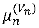
- V n denotes the latent variable which indicates the source that the observation Z n is assigned to.
- step S1 The membership computation of step S1 can be based either on:
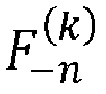
- the probability in frequency observation can be divided into two terms p 1 , and p 2 as p F n
- F ⁇ n k , ⁇ k p 1 F n ⁇ k .
- p 2 F n ⁇ k The design of p 1 , and p 2 can be proposed as follows:
- step S2 the observation classification can be based then either on:
- the database update of step S3 can be based either on:
- Figures 4a and 4b show an example of an interference environment.
- the interference activities in the frequency domain is depicted in Figure 4a and the respective geographical positions of interferers are shown in Figure 4b .
- a moving device observes the interference environment via a frequency hopping (FH) pattern, as presented typically in figure 2b for instance. Details of such interference observations can be obtained for example from document EP-3716506 .
- FH frequency hopping
- the Bayesian inference is used for the membership computation and the hard decision is used for the classification, in this example.
- the estimation is performed from scratch without any initial database.
- each label I1, I2, I3, I4 and I5 represents an interference source.
- the method implementation makes it possible to estimate five interference sources and attribute the observations to each one of them.
- Figure 6b the estimation of operation frequency and activation time are plotted for each interference source.
- Figure 6d the contours of probability for the source's position resulted from the Bayesian update, are displayed along with the true position of the interference sources.
- the present disclosure allows the usage of a frequency hopping system, for instance in 2.4GHz ISM band, for characterizing the interference along a predefined trajectory such as a railroad, thereby making it possible to reduce the impact of such interference for railways equipment and/or communicating devices embarked in a train.
- a device DEV for implementing the method above can comprise for example:
Landscapes
- Engineering & Computer Science (AREA)
- Quality & Reliability (AREA)
- Physics & Mathematics (AREA)
- Electromagnetism (AREA)
- Computer Networks & Wireless Communication (AREA)
- Signal Processing (AREA)
- Mobile Radio Communication Systems (AREA)
- Monitoring And Testing Of Transmission In General (AREA)
- Position Fixing By Use Of Radio Waves (AREA)
Abstract
Description
- The present disclosure is in the context of monitoring a radio environment.
- As many wireless communication systems nowadays operate in a public band, one must cope with the coexistence of interference. The characterization of interference helps monitoring the radio environment and/or managing the radio resource. In particular, it is sought for characterization of wireless interference.
- Interference monitoring in a radio environment where multiple interference sources exist requires usually an analysis of observation obtained from several devices. The problem is rather more complex when the sources move during the observations. The problem is usually to identify the interference as separated sources and to characterize then the following properties for each source:
- Operating frequency band,
- Geolocation,
- Activation rate.
- The present disclosure aims to improve the situation.
- To that end, it proposes a method for characterizing radiofrequency interference caused by a plurality of sources, comprising:
- using at least one observing device scanning successively a plurality of radiofrequency bands for performing interference measurements in said plurality of radiofrequency bands, in different space locations, and at different time instants, and providing observations at successive time instants of:
- * a current observing frequency,
- * a current position of the observing device, and
- * a received interference power in an observed frequency band,
- computing, for each interference source and each observation, a likelihood probability to attribute one observation to one interference source,
- using said likelihood probability computations to assign each of said observations to one interference source,
- for each interference source assigned with one of said observations, estimating a location and a frequency occupation of said interference source,
- More particularly, the aforesaid likelihood probability computing is based on both frequency observation and interference power observation.
- It is proposed therefore to use both the frequency observations and, here in particular, the power observations to compute the likelihood probabilities, the power observations being related to the distance between the interference source and the observing device.
- For example, the likelihood probability computing can involve a joint Bayesian inference of frequency observation and interference power observation. Alternatively, an Euclidean distance calculation approach can be used also.
- In an embodiment, a database storing previous detections can be used. Typically, in an embodiment, the aforesaid likelihood probability computing can use such a database storing, for each source of said interference sources, at least data of a location of said interference source and data of an occupation of at least two radiofrequency bands by said interference source.
- Typically, these stored data can be derived from previous observations. Therefore, said data of a location of the interference source can be a data of a past location of the source, and said data of an occupation of the interference source can be typically a data of a past frequency occupation by said source.
- The aforesaid database can be updated after each assignation of an observation to one interference source, in view of a next iteration of the method.
- Therefore, the use of the database storing data of previous identifications of interferers (location/frequency band(s) of interference) can facilitate a current determination of multiple sources of interference. Reversely, after a determination of interferers, the content of the database is preferably updated so that it can be used efficiently for a next future iteration of the method.
- In a particular embodiment, for each interference source, the database can provide at least one of:
- an average past position, and
- a probability map of a discretized past position.
- Therefore, the database can provide an average past position of a source, and more particularly this average can be weighted inversely as a function of at the date of determination of this source.
- The average past position can be used in a context of a "hard decision" embodiment which is specified below, and the probability map can be used in a context of a "source sampling" embodiment explained below also, depending for example on a level of confidence of a current determination of a source of interference.
- Moreover, for each interference source, the database can provide at least one of:
- an average radiofrequency band past occupation, and
- probability map of radiofrequency range past occupation.
- The database can store, for each interference source, data of occurrences of previous observations which were already assigned to this interference source.
- This information of previous observations associated to a source can help also for probability calculations of a current observation to be associated (or not) to this same source.
- For a current observation, the likelihood probability of one of the interference sources to be related to said current observation is computed on the basis of a comparison between data of said database and data of said given observation, and the aforesaid comparison comprises a determination of:
- - a similarity degree between a level of radiofrequency power measured in the current observation and a closest level of radiofrequency power corresponding to a source, given by a past position of this source in said database relatively to the current position of the observing device; and
- - and a similarity degree between a radiofrequency band which is occupied in the current observation and a radiofrequency band which was occupied by a source according to said database.
- Therefore, the likelihood probability is computed on the basis of two items which can finally correspond to one same source:
- The current position of this source relatively to the observing device, which is given by the radiofrequency power of the signal received and measured by the observing device, and
- The frequency band(s) where such a source is active.
- In the aforesaid "hard decision" embodiment, the assignation of at least one observation to one interference source can comprise:
- sorting the likelihood probabilities computed for each interference source to attribute said at least one observation to said interference source,
- selecting the highest computed likelihood probability to assign said at least one observation to the interference source having the highest computed likelihood probability.
- In this embodiment, the likelihood probabilities can be computed for example on the basis of Euclidian distance calculations of:
- a distance between the observing device and a source, in a radiofrequency power domain (linked therefore to the space domain typically), and
- a distance between a frequency band occupied by said source according to the database, and a frequency band where interference is measured according to said observation.
- In the "source sampling" embodiment, the assignation of at least one observation to one interference source comprises:
- sampling each source assignation based on a related computed likelihood probability, with an initial random draw followed by calculation iterations until successive samples converge to said related computed likelihood probability.
- For example, in view to choose the "hard decision" embodiment or the "source sampling" embodiment, each likelihood probability can be compared to a threshold and:
- if the computed likelihood probability is above said threshold, then the highest computed likelihood probability is selected to assign said at least one observation to the interference source having the highest computed likelihood probability (hard decision embodiment),
- if the computed likelihood probability is above said threshold, then the source assignation is sampled until convergence (source sampling embodiment).
- Regarding the observing device, in an embodiment, the observing device can move in successive known positions while said interference sources are assumed to be in fixed positions.
- For example, the observing device can be installed in a moving vehicle, such as a train, having a known trajectory, or can simply be equipped with a GPS to know its successive current positions.
- Alternatively, the aforesaid scanning of plurality of radiofrequency bands can be performed by at least three observing devices having known spatial positions (fixed positions for example), said spatial positions being not aligned, and the sources positions determination can be performed by triangulation over the three observing devices.
- The present disclosure can also aim at an observing device comprising a computer circuit to perform the method as presented above.
- It also aims at a system comprising at least three observing devices for performing the method.
- It also aims at a computer program comprising instructions which, when the program is executed by a computer, cause the computer to carry out the method.
- It also aims at a non-transitory computer storage medium, storing instructions code of such a computer program.
- More details and advantages of the present disclosure will be understood when reading the following description of embodiments given below as examples, and will appear from the related drawings where:
-
Figure 1 shows the main steps of the analysis processing of interference, -
Figures 2a and 2b show the setting of a moving observing device: a) in spatial domain, and b) in frequency domain, -
Figures 3a and 3b show the setting of a plurality of observing devices: a) in spatial domain, and b) in frequency domain, -
Figure 4a shows the interference activity in the frequency domain of interference sources andFigure 4b shows their true respective positions in spatial domain, -
Figures 5a and 5b show the observation on a moving device respectively in the frequency domain via frequency hopping and in spatial domain via received power measurements, -
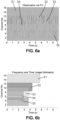
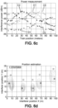
Figures 6a to 6d show the result of the implementation of the method with a moving device and with five interference sources active in different channels (five different colours or grey levels infigure 6a ), active during different time periods (figure 6b ), relatively to different positions of the moving device (figure 6c ), and having respective positions finally determined infigure 6d . -
Figure 7 shows an interference analysis device for performing the method described above. - Referring to
figure 1 , given current observations 12 (mandatory) and an optional database 11 (the database can be built in prior steps of the method from precedent observations) of an environment comprising interferers for a communication system, the method proposes to analyse the interference in terms of frequency usage, geolocation characteristic and/or time usage. An interference analysis device performs observations in multiple frequencies, locations, and time instants. - The first input for each processing step is the interference database. For each separated current interference source, the database provides in step 11 the following information:
- Position information, being either:
- ∘ The average position in considered space, or
- ∘ A probability map of a discretized position of considered space,
- Frequency information, being either:
- ∘ The average frequency, or
- ∘ A probability map of considered frequency range,
- Associated observations:
- ∘ Previous observations which were already assigned to the current interference source.
- The aforesaid "current observations" can consist in step I2 of:
- the position of the observing device (the aforesaid interference analysis device),
- the received interference power, and
- the observed frequency channel index.
- Indeed, the interference analysis device scans a given frequency band over a plurality of radiofrequency channels (for example sixteen channels in the examples of the figures commented below), each channel having its proper index.
- Then, step S1 comprises a membership computation. Using the database of interference sources, the likelihood of the current observations for each source is computed based on a Bayesian Inference. The calculation measures:
- a similarity degree between a level of power given by the observation and a closest level of power of a source, given by a position of this source in the database; and
- and a similarity degree between the frequency observation and the source's frequency database.
- This probability reflects how strong the connection between an observation and a source is.
- Then, step S2 comprises observation classification. Using the probability calculated in the previous step, step S1, the observation is assigned to a source. This step S2 can be performed according to several embodiments:
- a "hard decision" embodiment where the assigned source is decided to be the one with highest probability, the decision being made once,
- a "source sampling" embodiment where the source decision is sampled based on its estimated probability. This technique requires iterations to enable the samples to converge to the estimated probability.
- A "hybrid method" embodiment where both the aforementioned methods are adopted, so as to balance the speed of the hard decision method and the stability of the source sampling method. Typically, a threshold of probability can be defined, above which the hard decision can be taken and below which the source sampling is rather used.
- Then, step S3 comprises the database update. Once the observation is associated to a source, the database of this source evolves according to the observation and is updated thus accordingly.
- Finally, in step O1, the newly updated database can be used in a next iteration of the process.
- The details for each step of the general method are described below.
- In the interfered radio environment, it is assumed that the interference is generated by one or several radio sources. One source distinguishes to another by its geometrical position and/or its operating frequency band.
- To be able to monitor the environment, the observation of interference is required. To that end, the observations can be obtained by any of the following devices:
- One device with the capability of observing in multiple frequencies and in multiple locations: this device can be a wideband transceiver or a frequency-hoping transceiver, mounted on a moving vehicle (train, or car, or boat, etc.). An example for this setting is illustrated in
figure 2a showing the change in the spatial domain, and infigure 2b showing the change in the frequency domain; - Or multiple devices with multiple operating frequency (possibly a wideband transceiver or a frequency-hoping transceiver): these devices are located in at least three non-aligned positions to enable the triangulation in geolocation. More than three positions are preferable to enhance the accuracy. An example of arrangement of devices in space and in frequency is shown respectively in
Figures 3a and 3b . - For the observing device, since there does not exist any signalling exchange with interference sources, the interference transmission is completely random. In other words, the device blindly observes the interference without knowing the interference location. Therefore, the observation data can be seen as a mixed signal.
- Hereafter the following notations are adopted:
- Concerning an interference source Sk :
- ∘ k is the source's index
- ∘ θ k is the source's position
- ∘ φ k is the source's operating frequency
- Concerning an observation Z n :
- ∘ n is the index of observation
- ∘ Tn is the position of observing device
- ∘ Wn is the received interference power
- ∘ Fn is the observed frequency.
- For the estimation of the received power, it is assumed at the moment the observation Z n is obtained, that the interference source Sk is emitting. The received power (in dB for example) at the observing device can be modelled as


- The operating frequency of the interference source Sk can be modelled by two parameters:

- To be able to analyse the interference, it is needed to classify the observations into separated sources. A database for each source then can be built and updated according to its belonged observations. This database afterward serves the next observation classification as a prior knowledge.
- Hereafter, Vn denotes the latent variable which indicates the source that the observation Z n is assigned to. At the beginning of the analysis of observation Zn , the following statements are assumed:
- (.)-n denotes the existing set of a variable before having the observation Z n
- There exists K interference sources: k = 1.. K
- For a source Sk,

- The database of source position is available under the form of probability as follows

- The database of source operating frequency is available under the form of probability as follows

- The membership computation of step S1 can be based either on:
- a) Euclidean distance :
Given the average positionθ k and average frequencyφ k , the membership computation can be performed by the Euclidean distance between the observation and the interference source. In the spatial domain, the distance is proposed to be computed as follows

- b) Bayesian inference :
In another approach, the membership computation can be proposed to be computed as corresponding to the probability that the observation can be a part of a source. Hereafter is denoted the latent variable Vn, corresponding to the time instant n, to indicate which source the observation belongs to. For an observation Z n = (Tn,Wn,Fn ), the following probability can be considered


-

-

-

-

-

-
- The probability in frequency observation can be divided into two terms p 1, and p 2 as

- p 1, to indicate whether Fn is inside φk

- p 2 to determine how the fit is between the set of assigned frequencies

- Then, for the implementation of step S2, the observation classification can be based then either on:
- a) Euclidean distance
The observation is classified by a hard decision according to its distance to the sources. In this sense, the observation is associated to the source with smallest distance, such as:
- b) Bayesian inference
The observation classification can be derived by one of the following methods:- ∘ Hard decision:
The decision is made once according to the best membership probability
- ∘ Sampling method:
A random sample of Vn is drawn according to the membership probability p(Vn |Zn,Z-n,V-n ). This approach requires iterations over the sampling which allow then the value of Vn to converge. - ∘ Hybrid approach:
- In order to adopt the advantage of two both aforementioned methods, the rapidity of the "hard decision" method and the stability of the sampling method, a hybrid approach is proposed below.
- First, the membership probability is normalized as follows

- Second, a threshold for the normalized membership probability is defined. In the present case, the best normalized membership probability falls above this threshold, and it can be stated that the best source for the observation is evident, so that the hard decision method can be implemented. For the other cases, the best source is ambiguous, thus the sampling method should rather be implemented.
- ∘ Hard decision:
- The database update of step S3 can be based either on:
- a) Euclidean distance
Supposing that the observation Z n is associated to the source k, then the average position and frequency can be updated as follows:
- b) Bayesian inference
For the geolocation database, the following probability is computed for the update:

-
Figures 4a and 4b show an example of an interference environment. The interference activities in the frequency domain is depicted inFigure 4a and the respective geographical positions of interferers are shown inFigure 4b . - In this interfering environment, a moving device observes the interference environment via a frequency hopping (FH) pattern, as presented typically in
figure 2b for instance. Details of such interference observations can be obtained for example from documentEP-3716506 . - The initial corresponding observations obtained on the moving device are showed in
figure 5a (in the frequency domain) and infigure 5b (in the spatial domain). - To analyse the environment, the Bayesian inference is used for the membership computation and the hard decision is used for the classification, in this example. The estimation is performed from scratch without any initial database.
- The result of observation classification is showed in
Figure 6a andFigure 6c in the frequency domain and received power domain, respectively. In both figures, each label I1, I2, I3, I4 and I5 represents an interference source. As it can be seen, the method implementation makes it possible to estimate five interference sources and attribute the observations to each one of them. InFigure 6b , the estimation of operation frequency and activation time are plotted for each interference source. InFigure 6d , the contours of probability for the source's position resulted from the Bayesian update, are displayed along with the true position of the interference sources. - Therefore, the present disclosure allows the usage of a frequency hopping system, for instance in 2.4GHz ISM band, for characterizing the interference along a predefined trajectory such as a railroad, thereby making it possible to reduce the impact of such interference for railways equipment and/or communicating devices embarked in a train.
- With reference to
figure 7 , a device DEV for implementing the method above can comprise for example: - An input interface IN (such as for example a radiofrequency antenna) to receive radiofrequency signals and measure radiofrequency power in each frequency channel according to a frequency hopping pattern as presented in
figure 2b for instance, - A memory MEM to store at least instructions of a computer program to implement the method presented above, and possibly also to store data of the database DB used in the method,
- A processor PROC accessing to said memory MEM and database DB so as to implement the method and finally determine current interference sources (positions and radiofrequency active bands),
- An output interface OUT to deliver data of such a determination, that can feed the database DB so as to update its content,
- And optionally in an embodiment where the device DEV is mobile, a GPS chip to determine the exact location of the device at each of its observations.
Claims (17)
Priority Applications (5)
| Application Number | Priority Date | Filing Date | Title |
|---|---|---|---|
| EP22305221.8A EP4236117B1 (en) | 2022-02-28 | 2022-02-28 | Improved characterization of a radiofrequency environment comprising a plurality of interference sources |
| US18/727,128 US20250105934A1 (en) | 2022-02-28 | 2022-09-30 | A method for characterizing radiofrequency interference caused by a plurality of sources, an observing device, a system, and a computer program |
| JP2024555571A JP7763967B2 (en) | 2022-02-28 | 2022-09-30 | Method, observation device, system and computer program for characterizing radio frequency interference caused by multiple sources |
| CN202280087905.XA CN118696514A (en) | 2022-02-28 | 2022-09-30 | Method, observation device, system and computer program for characterizing radio frequency interference caused by multiple sources |
| PCT/JP2022/037526 WO2023162322A1 (en) | 2022-02-28 | 2022-09-30 | A method for characterizing radiofrequency interference caused by a plurality of sources, an observing device, a system, and a computer program |
Applications Claiming Priority (1)
| Application Number | Priority Date | Filing Date | Title |
|---|---|---|---|
| EP22305221.8A EP4236117B1 (en) | 2022-02-28 | 2022-02-28 | Improved characterization of a radiofrequency environment comprising a plurality of interference sources |
Publications (2)
| Publication Number | Publication Date |
|---|---|
| EP4236117A1 true EP4236117A1 (en) | 2023-08-30 |
| EP4236117B1 EP4236117B1 (en) | 2025-02-12 |
Family
ID=81850394
Family Applications (1)
| Application Number | Title | Priority Date | Filing Date |
|---|---|---|---|
| EP22305221.8A Active EP4236117B1 (en) | 2022-02-28 | 2022-02-28 | Improved characterization of a radiofrequency environment comprising a plurality of interference sources |
Country Status (5)
| Country | Link |
|---|---|
| US (1) | US20250105934A1 (en) |
| EP (1) | EP4236117B1 (en) |
| JP (1) | JP7763967B2 (en) |
| CN (1) | CN118696514A (en) |
| WO (1) | WO2023162322A1 (en) |
Citations (3)
| Publication number | Priority date | Publication date | Assignee | Title |
|---|---|---|---|---|
| US20120045012A1 (en) * | 2008-09-26 | 2012-02-23 | Motorola, Inc. | Method and device for transmitting data in a wireless communication network |
| EP3716506A1 (en) | 2019-03-27 | 2020-09-30 | Mitsubishi Electric R&D Centre Europe B.V. | Improved wifi interference identification for a use in a public frequency hopping system |
| US20210384994A1 (en) * | 2020-06-09 | 2021-12-09 | Verizon Patent And Licensing Inc. | Systems and methods for identifying a source of radio frequency interference in a wireless network |
Family Cites Families (4)
| Publication number | Priority date | Publication date | Assignee | Title |
|---|---|---|---|---|
| US8138975B2 (en) | 2008-12-30 | 2012-03-20 | Trueposition, Inc. | Interference detection, characterization and location in a wireless communications or broadcast system |
| JP7131218B2 (en) | 2018-09-07 | 2022-09-06 | 日本電気株式会社 | Radio wave monitoring system, radio wave monitoring processing device, radio wave monitoring method and program |
| JP2021119332A (en) | 2020-01-30 | 2021-08-12 | 関西電力株式会社 | Radio signal generation location estimation method |
| EP3919344B1 (en) | 2020-06-05 | 2024-08-28 | Mitsubishi Electric R&D Centre Europe B.V. | Method for geolocating an interference source in a communication-based transport system |
-
2022
- 2022-02-28 EP EP22305221.8A patent/EP4236117B1/en active Active
- 2022-09-30 CN CN202280087905.XA patent/CN118696514A/en active Pending
- 2022-09-30 US US18/727,128 patent/US20250105934A1/en active Pending
- 2022-09-30 JP JP2024555571A patent/JP7763967B2/en active Active
- 2022-09-30 WO PCT/JP2022/037526 patent/WO2023162322A1/en not_active Ceased
Patent Citations (3)
| Publication number | Priority date | Publication date | Assignee | Title |
|---|---|---|---|---|
| US20120045012A1 (en) * | 2008-09-26 | 2012-02-23 | Motorola, Inc. | Method and device for transmitting data in a wireless communication network |
| EP3716506A1 (en) | 2019-03-27 | 2020-09-30 | Mitsubishi Electric R&D Centre Europe B.V. | Improved wifi interference identification for a use in a public frequency hopping system |
| US20210384994A1 (en) * | 2020-06-09 | 2021-12-09 | Verizon Patent And Licensing Inc. | Systems and methods for identifying a source of radio frequency interference in a wireless network |
Also Published As
| Publication number | Publication date |
|---|---|
| JP7763967B2 (en) | 2025-11-04 |
| JP2024545737A (en) | 2024-12-10 |
| EP4236117B1 (en) | 2025-02-12 |
| CN118696514A (en) | 2024-09-24 |
| WO2023162322A1 (en) | 2023-08-31 |
| US20250105934A1 (en) | 2025-03-27 |
Similar Documents
| Publication | Publication Date | Title |
|---|---|---|
| US12526644B2 (en) | Learning-based spectrum occupancy prediction exploiting multi-dimensional correlation | |
| US20260023993A1 (en) | Radio frequency band segmentation, signal detection and labelling using machine learning | |
| US9503855B2 (en) | Terminal apparatus, position estimating method, position estimating system, and computer-readable storage medium | |
| Toma et al. | AI-based abnormality detection at the PHY-layer of cognitive radio by learning generative models | |
| Cohen et al. | Calibrating AI models for wireless communications via conformal prediction | |
| US8923771B2 (en) | Method, apparatus and computer program product for identifying frequency bands, and a method, apparatus and computer program product for evaluating performance | |
| US9473257B1 (en) | Radio communication system utilizing a radio signal classifier | |
| US12372601B2 (en) | Method for geolocating interference source in communication-based transport system | |
| CN113114399A (en) | Three-dimensional spectrum situation complementing method and device based on generation countermeasure network | |
| Toma et al. | Deep learning for spectrum anomaly detection in cognitive mmWave radios | |
| US11108432B2 (en) | Device and method for estimating interference and radiofrequency communication system | |
| JP6627496B2 (en) | Management device, program to be executed by computer, and computer-readable recording medium recording the program | |
| Zayen et al. | Blind spectrum sensing for cognitive radio based on model selection | |
| Chirov et al. | Spectrum occupancy prediction algorithm using artificial neural networks | |
| EP4236117B1 (en) | Improved characterization of a radiofrequency environment comprising a plurality of interference sources | |
| KR20120086023A (en) | Cognitive radio communication system engine unit using chaotic property | |
| CN109787697B (en) | Frequency spectrum sensing method based on wireless fingerprint database | |
| JP7272578B2 (en) | Computer-readable recording medium recording a program to be executed by a management device, a computer, and the program | |
| Tsakmalis et al. | Power control in cognitive radio networks using cooperative modulation and coding classification | |
| Kopyto et al. | Deep Learning-Based Dynamic Spectrum Access for Coexistence of Aeronautical Communication Systems | |
| Manjunath et al. | Mechanisms for the estimation of prediction intervals in vehicular communication scenarios | |
| US20240183931A1 (en) | Computer implemented method for estimating interferers of radiofrequency system, computer program, and device | |
| KR102923619B1 (en) | Cognitive-based frequency automatic switching apparatus and reliability-based carrier selection method thereof | |
| White | Constrained Clustering for Frequency Hopping Spread Spectrum Signal Separation | |
| Bezerra et al. | Predicting consecutive spectrum opportunities with hidden Markov models |
Legal Events
| Date | Code | Title | Description |
|---|---|---|---|
| PUAI | Public reference made under article 153(3) epc to a published international application that has entered the european phase |
Free format text: ORIGINAL CODE: 0009012 |
|
| STAA | Information on the status of an ep patent application or granted ep patent |
Free format text: STATUS: THE APPLICATION HAS BEEN PUBLISHED |
|
| AK | Designated contracting states |
Kind code of ref document: A1 Designated state(s): AL AT BE BG CH CY CZ DE DK EE ES FI FR GB GR HR HU IE IS IT LI LT LU LV MC MK MT NL NO PL PT RO RS SE SI SK SM TR |
|
| STAA | Information on the status of an ep patent application or granted ep patent |
Free format text: STATUS: REQUEST FOR EXAMINATION WAS MADE |
|
| 17P | Request for examination filed |
Effective date: 20231109 |
|
| RBV | Designated contracting states (corrected) |
Designated state(s): AL AT BE BG CH CY CZ DE DK EE ES FI FR GB GR HR HU IE IS IT LI LT LU LV MC MK MT NL NO PL PT RO RS SE SI SK SM TR |
|
| GRAP | Despatch of communication of intention to grant a patent |
Free format text: ORIGINAL CODE: EPIDOSNIGR1 |
|
| STAA | Information on the status of an ep patent application or granted ep patent |
Free format text: STATUS: GRANT OF PATENT IS INTENDED |
|
| INTG | Intention to grant announced |
Effective date: 20240927 |
|
| P01 | Opt-out of the competence of the unified patent court (upc) registered |
Free format text: CASE NUMBER: APP_57824/2024 Effective date: 20241023 |
|
| GRAS | Grant fee paid |
Free format text: ORIGINAL CODE: EPIDOSNIGR3 |
|
| GRAA | (expected) grant |
Free format text: ORIGINAL CODE: 0009210 |
|
| STAA | Information on the status of an ep patent application or granted ep patent |
Free format text: STATUS: THE PATENT HAS BEEN GRANTED |
|
| AK | Designated contracting states |
Kind code of ref document: B1 Designated state(s): AL AT BE BG CH CY CZ DE DK EE ES FI FR GB GR HR HU IE IS IT LI LT LU LV MC MK MT NL NO PL PT RO RS SE SI SK SM TR |
|
| REG | Reference to a national code |
Ref country code: GB Ref legal event code: FG4D |
|
| REG | Reference to a national code |
Ref country code: CH Ref legal event code: EP |
|
| REG | Reference to a national code |
Ref country code: DE Ref legal event code: R096 Ref document number: 602022010481 Country of ref document: DE |
|
| REG | Reference to a national code |
Ref country code: IE Ref legal event code: FG4D |
|
| REG | Reference to a national code |
Ref country code: NL Ref legal event code: MP Effective date: 20250212 |
|
| PG25 | Lapsed in a contracting state [announced via postgrant information from national office to epo] |
Ref country code: RS Free format text: LAPSE BECAUSE OF FAILURE TO SUBMIT A TRANSLATION OF THE DESCRIPTION OR TO PAY THE FEE WITHIN THE PRESCRIBED TIME-LIMIT Effective date: 20250512 |
|
| PG25 | Lapsed in a contracting state [announced via postgrant information from national office to epo] |
Ref country code: FI Free format text: LAPSE BECAUSE OF FAILURE TO SUBMIT A TRANSLATION OF THE DESCRIPTION OR TO PAY THE FEE WITHIN THE PRESCRIBED TIME-LIMIT Effective date: 20250212 |
|
| PG25 | Lapsed in a contracting state [announced via postgrant information from national office to epo] |
Ref country code: PL Free format text: LAPSE BECAUSE OF FAILURE TO SUBMIT A TRANSLATION OF THE DESCRIPTION OR TO PAY THE FEE WITHIN THE PRESCRIBED TIME-LIMIT Effective date: 20250212 |
|
| PG25 | Lapsed in a contracting state [announced via postgrant information from national office to epo] |
Ref country code: ES Free format text: LAPSE BECAUSE OF FAILURE TO SUBMIT A TRANSLATION OF THE DESCRIPTION OR TO PAY THE FEE WITHIN THE PRESCRIBED TIME-LIMIT Effective date: 20250212 |
|
| REG | Reference to a national code |
Ref country code: LT Ref legal event code: MG9D |
|
| PG25 | Lapsed in a contracting state [announced via postgrant information from national office to epo] |
Ref country code: IS Free format text: LAPSE BECAUSE OF FAILURE TO SUBMIT A TRANSLATION OF THE DESCRIPTION OR TO PAY THE FEE WITHIN THE PRESCRIBED TIME-LIMIT Effective date: 20250612 Ref country code: NO Free format text: LAPSE BECAUSE OF FAILURE TO SUBMIT A TRANSLATION OF THE DESCRIPTION OR TO PAY THE FEE WITHIN THE PRESCRIBED TIME-LIMIT Effective date: 20250512 |
|
| PG25 | Lapsed in a contracting state [announced via postgrant information from national office to epo] |
Ref country code: NL Free format text: LAPSE BECAUSE OF FAILURE TO SUBMIT A TRANSLATION OF THE DESCRIPTION OR TO PAY THE FEE WITHIN THE PRESCRIBED TIME-LIMIT Effective date: 20250212 |
|
| PG25 | Lapsed in a contracting state [announced via postgrant information from national office to epo] |
Ref country code: HR Free format text: LAPSE BECAUSE OF FAILURE TO SUBMIT A TRANSLATION OF THE DESCRIPTION OR TO PAY THE FEE WITHIN THE PRESCRIBED TIME-LIMIT Effective date: 20250212 |
|
| PG25 | Lapsed in a contracting state [announced via postgrant information from national office to epo] |
Ref country code: PT Free format text: LAPSE BECAUSE OF FAILURE TO SUBMIT A TRANSLATION OF THE DESCRIPTION OR TO PAY THE FEE WITHIN THE PRESCRIBED TIME-LIMIT Effective date: 20250612 Ref country code: LV Free format text: LAPSE BECAUSE OF FAILURE TO SUBMIT A TRANSLATION OF THE DESCRIPTION OR TO PAY THE FEE WITHIN THE PRESCRIBED TIME-LIMIT Effective date: 20250212 |
|
| PG25 | Lapsed in a contracting state [announced via postgrant information from national office to epo] |
Ref country code: GR Free format text: LAPSE BECAUSE OF FAILURE TO SUBMIT A TRANSLATION OF THE DESCRIPTION OR TO PAY THE FEE WITHIN THE PRESCRIBED TIME-LIMIT Effective date: 20250513 Ref country code: BG Free format text: LAPSE BECAUSE OF FAILURE TO SUBMIT A TRANSLATION OF THE DESCRIPTION OR TO PAY THE FEE WITHIN THE PRESCRIBED TIME-LIMIT Effective date: 20250212 |
|
| REG | Reference to a national code |
Ref country code: AT Ref legal event code: MK05 Ref document number: 1767114 Country of ref document: AT Kind code of ref document: T Effective date: 20250212 |
|
| PG25 | Lapsed in a contracting state [announced via postgrant information from national office to epo] |
Ref country code: SE Free format text: LAPSE BECAUSE OF FAILURE TO SUBMIT A TRANSLATION OF THE DESCRIPTION OR TO PAY THE FEE WITHIN THE PRESCRIBED TIME-LIMIT Effective date: 20250212 |
|
| REG | Reference to a national code |
Ref country code: CH Ref legal event code: PL |
|
| PG25 | Lapsed in a contracting state [announced via postgrant information from national office to epo] |
Ref country code: SM Free format text: LAPSE BECAUSE OF FAILURE TO SUBMIT A TRANSLATION OF THE DESCRIPTION OR TO PAY THE FEE WITHIN THE PRESCRIBED TIME-LIMIT Effective date: 20250212 |
|
| PG25 | Lapsed in a contracting state [announced via postgrant information from national office to epo] |
Ref country code: DK Free format text: LAPSE BECAUSE OF FAILURE TO SUBMIT A TRANSLATION OF THE DESCRIPTION OR TO PAY THE FEE WITHIN THE PRESCRIBED TIME-LIMIT Effective date: 20250212 |
|
| PG25 | Lapsed in a contracting state [announced via postgrant information from national office to epo] |
Ref country code: LU Free format text: LAPSE BECAUSE OF NON-PAYMENT OF DUE FEES Effective date: 20250228 Ref country code: IT Free format text: LAPSE BECAUSE OF FAILURE TO SUBMIT A TRANSLATION OF THE DESCRIPTION OR TO PAY THE FEE WITHIN THE PRESCRIBED TIME-LIMIT Effective date: 20250212 |
|
| PG25 | Lapsed in a contracting state [announced via postgrant information from national office to epo] |
Ref country code: AT Free format text: LAPSE BECAUSE OF FAILURE TO SUBMIT A TRANSLATION OF THE DESCRIPTION OR TO PAY THE FEE WITHIN THE PRESCRIBED TIME-LIMIT Effective date: 20250212 |
|
| PG25 | Lapsed in a contracting state [announced via postgrant information from national office to epo] |
Ref country code: CH Free format text: LAPSE BECAUSE OF NON-PAYMENT OF DUE FEES Effective date: 20250228 |
|
| PG25 | Lapsed in a contracting state [announced via postgrant information from national office to epo] |
Ref country code: EE Free format text: LAPSE BECAUSE OF FAILURE TO SUBMIT A TRANSLATION OF THE DESCRIPTION OR TO PAY THE FEE WITHIN THE PRESCRIBED TIME-LIMIT Effective date: 20250212 Ref country code: CZ Free format text: LAPSE BECAUSE OF FAILURE TO SUBMIT A TRANSLATION OF THE DESCRIPTION OR TO PAY THE FEE WITHIN THE PRESCRIBED TIME-LIMIT Effective date: 20250212 |
|
| PG25 | Lapsed in a contracting state [announced via postgrant information from national office to epo] |
Ref country code: RO Free format text: LAPSE BECAUSE OF FAILURE TO SUBMIT A TRANSLATION OF THE DESCRIPTION OR TO PAY THE FEE WITHIN THE PRESCRIBED TIME-LIMIT Effective date: 20250212 |
|
| PG25 | Lapsed in a contracting state [announced via postgrant information from national office to epo] |
Ref country code: SK Free format text: LAPSE BECAUSE OF FAILURE TO SUBMIT A TRANSLATION OF THE DESCRIPTION OR TO PAY THE FEE WITHIN THE PRESCRIBED TIME-LIMIT Effective date: 20250212 |
|
| REG | Reference to a national code |
Ref country code: DE Ref legal event code: R097 Ref document number: 602022010481 Country of ref document: DE |
|
| REG | Reference to a national code |
Ref country code: BE Ref legal event code: MM Effective date: 20250228 |
|
| PLBE | No opposition filed within time limit |
Free format text: ORIGINAL CODE: 0009261 |
|
| STAA | Information on the status of an ep patent application or granted ep patent |
Free format text: STATUS: NO OPPOSITION FILED WITHIN TIME LIMIT |
|
| PG25 | Lapsed in a contracting state [announced via postgrant information from national office to epo] |
Ref country code: MC Free format text: LAPSE BECAUSE OF FAILURE TO SUBMIT A TRANSLATION OF THE DESCRIPTION OR TO PAY THE FEE WITHIN THE PRESCRIBED TIME-LIMIT Effective date: 20250212 |
|
| PG25 | Lapsed in a contracting state [announced via postgrant information from national office to epo] |
Ref country code: BE Free format text: LAPSE BECAUSE OF NON-PAYMENT OF DUE FEES Effective date: 20250228 |
|
| PG25 | Lapsed in a contracting state [announced via postgrant information from national office to epo] |
Ref country code: IE Free format text: LAPSE BECAUSE OF NON-PAYMENT OF DUE FEES Effective date: 20250228 |
|
| 26N | No opposition filed |
Effective date: 20251113 |
|
| PGFP | Annual fee paid to national office [announced via postgrant information from national office to epo] |
Ref country code: GB Payment date: 20260219 Year of fee payment: 5 |
|
| PGFP | Annual fee paid to national office [announced via postgrant information from national office to epo] |
Ref country code: DE Payment date: 20260206 Year of fee payment: 5 |
|
| PGFP | Annual fee paid to national office [announced via postgrant information from national office to epo] |
Ref country code: FR Payment date: 20260121 Year of fee payment: 5 |