EP4235929A1 - Secondary battery - Google Patents
Secondary battery Download PDFInfo
- Publication number
- EP4235929A1 EP4235929A1 EP21886560.8A EP21886560A EP4235929A1 EP 4235929 A1 EP4235929 A1 EP 4235929A1 EP 21886560 A EP21886560 A EP 21886560A EP 4235929 A1 EP4235929 A1 EP 4235929A1
- Authority
- EP
- European Patent Office
- Prior art keywords
- notch
- cap
- secondary battery
- opening
- diameter
- Prior art date
- Legal status (The legal status is an assumption and is not a legal conclusion. Google has not performed a legal analysis and makes no representation as to the accuracy of the status listed.)
- Granted
Links
Images


Classifications
-
- H—ELECTRICITY
- H01—ELECTRIC ELEMENTS
- H01M—PROCESSES OR MEANS, e.g. BATTERIES, FOR THE DIRECT CONVERSION OF CHEMICAL ENERGY INTO ELECTRICAL ENERGY
- H01M50/00—Constructional details or processes of manufacture of the non-active parts of electrochemical cells other than fuel cells, e.g. hybrid cells
- H01M50/30—Arrangements for facilitating escape of gases
- H01M50/342—Non-re-sealable arrangements
- H01M50/3425—Non-re-sealable arrangements in the form of rupturable membranes or weakened parts, e.g. pierced with the aid of a sharp member
-
- H—ELECTRICITY
- H01—ELECTRIC ELEMENTS
- H01M—PROCESSES OR MEANS, e.g. BATTERIES, FOR THE DIRECT CONVERSION OF CHEMICAL ENERGY INTO ELECTRICAL ENERGY
- H01M50/00—Constructional details or processes of manufacture of the non-active parts of electrochemical cells other than fuel cells, e.g. hybrid cells
- H01M50/10—Primary casings; Jackets or wrappings
- H01M50/102—Primary casings; Jackets or wrappings characterised by their shape or physical structure
- H01M50/107—Primary casings; Jackets or wrappings characterised by their shape or physical structure having curved cross-section, e.g. round or elliptic
-
- H—ELECTRICITY
- H01—ELECTRIC ELEMENTS
- H01M—PROCESSES OR MEANS, e.g. BATTERIES, FOR THE DIRECT CONVERSION OF CHEMICAL ENERGY INTO ELECTRICAL ENERGY
- H01M50/00—Constructional details or processes of manufacture of the non-active parts of electrochemical cells other than fuel cells, e.g. hybrid cells
- H01M50/10—Primary casings; Jackets or wrappings
- H01M50/147—Lids or covers
- H01M50/148—Lids or covers characterised by their shape
- H01M50/152—Lids or covers characterised by their shape for cells having curved cross-section, e.g. round or elliptic
-
- H—ELECTRICITY
- H01—ELECTRIC ELEMENTS
- H01M—PROCESSES OR MEANS, e.g. BATTERIES, FOR THE DIRECT CONVERSION OF CHEMICAL ENERGY INTO ELECTRICAL ENERGY
- H01M50/00—Constructional details or processes of manufacture of the non-active parts of electrochemical cells other than fuel cells, e.g. hybrid cells
- H01M50/10—Primary casings; Jackets or wrappings
- H01M50/183—Sealing members
- H01M50/186—Sealing members characterised by the disposition of the sealing members
-
- H—ELECTRICITY
- H01—ELECTRIC ELEMENTS
- H01M—PROCESSES OR MEANS, e.g. BATTERIES, FOR THE DIRECT CONVERSION OF CHEMICAL ENERGY INTO ELECTRICAL ENERGY
- H01M50/00—Constructional details or processes of manufacture of the non-active parts of electrochemical cells other than fuel cells, e.g. hybrid cells
- H01M50/50—Current conducting connections for cells or batteries
- H01M50/528—Fixed electrical connections, i.e. not intended for disconnection
-
- H—ELECTRICITY
- H01—ELECTRIC ELEMENTS
- H01M—PROCESSES OR MEANS, e.g. BATTERIES, FOR THE DIRECT CONVERSION OF CHEMICAL ENERGY INTO ELECTRICAL ENERGY
- H01M50/00—Constructional details or processes of manufacture of the non-active parts of electrochemical cells other than fuel cells, e.g. hybrid cells
- H01M50/50—Current conducting connections for cells or batteries
- H01M50/531—Electrode connections inside a battery casing
-
- H—ELECTRICITY
- H01—ELECTRIC ELEMENTS
- H01M—PROCESSES OR MEANS, e.g. BATTERIES, FOR THE DIRECT CONVERSION OF CHEMICAL ENERGY INTO ELECTRICAL ENERGY
- H01M50/00—Constructional details or processes of manufacture of the non-active parts of electrochemical cells other than fuel cells, e.g. hybrid cells
- H01M50/50—Current conducting connections for cells or batteries
- H01M50/543—Terminals
- H01M50/552—Terminals characterised by their shape
- H01M50/559—Terminals adapted for cells having curved cross-section, e.g. round, elliptic or button cells
-
- H—ELECTRICITY
- H01—ELECTRIC ELEMENTS
- H01M—PROCESSES OR MEANS, e.g. BATTERIES, FOR THE DIRECT CONVERSION OF CHEMICAL ENERGY INTO ELECTRICAL ENERGY
- H01M2200/00—Safety devices for primary or secondary batteries
- H01M2200/20—Pressure-sensitive devices
-
- Y—GENERAL TAGGING OF NEW TECHNOLOGICAL DEVELOPMENTS; GENERAL TAGGING OF CROSS-SECTIONAL TECHNOLOGIES SPANNING OVER SEVERAL SECTIONS OF THE IPC; TECHNICAL SUBJECTS COVERED BY FORMER USPC CROSS-REFERENCE ART COLLECTIONS [XRACs] AND DIGESTS
- Y02—TECHNOLOGIES OR APPLICATIONS FOR MITIGATION OR ADAPTATION AGAINST CLIMATE CHANGE
- Y02E—REDUCTION OF GREENHOUSE GAS [GHG] EMISSIONS, RELATED TO ENERGY GENERATION, TRANSMISSION OR DISTRIBUTION
- Y02E60/00—Enabling technologies; Technologies with a potential or indirect contribution to GHG emissions mitigation
- Y02E60/10—Energy storage using batteries
Definitions
- the present invention relates to a secondary battery.
- a secondary battery is a rechargeable and dischargeable battery.
- a low-capacity secondary battery may be used for various portable small-sized electronic devices, such as a smartphone, a feature phone, a notebook computer, a digital camera, or a camcorder, and a high-capacity secondary battery is widely used as a power source for motor drives, such as those in hybrid vehicles or electric vehicles.
- These lithium ion secondary batteries may be classified into cylindrical, prismatic, and pouch-type secondary batteries in terms of shape.
- a cylindrical lithium secondary battery generally includes a cylindrical electrode assembly, a cylindrical case to which the electrode assembly is coupled, an electrolyte injected into the case to allow movement of lithium ions, and a cap assembly that is coupled to one side of the case to prevent leakage of the electrolyte and prevents separation of the electrode assembly.
- the present invention provides a secondary battery capable of improving safety by easily discharging internal gas.
- a secondary battery according to the present invention may include: an electrode assembly; a case in which the electrode assembly is accommodated; and a cap assembly which is coupled to the top of the case and comprises a cap-up having opening, a safety vent provided under the cap-up and having a notch to be ruptured at a predetermined pressure or higher, and a cap-down provided under the safety vent and electrically connected to the electrode assembly, wherein the notch is exposed through the opening.
- the area of the opening may include an inner area positioned inside the notch and an outer area positioned outside the notch based on the line where the notch is formed, and the inner area may be larger than the outer area.
- the inner area may be set to 55% or more of the total area of the opening.
- the cap-up may include a terminal portion protruding upward, a coupling portion positioned on an outer periphery of the terminal portion and coupled to the safety vent, and a connection portion connecting the terminal portion and the coupling portion, and the opening is formed in the connecting portion.
- An inner area of the opening may be determined by a diameter of the terminal portion and a diameter of the notch.
- An outer area of the opening may be determined by a diameter of the notch and a diameter of the connecting portion.
- the diameter of the notch may be larger than the diameter of the terminal portion and smaller than the diameter of the connecting portion.
- a gas vent hole located below the notch may be formed in the cap-down.
- a gasket disposed between the cap assembly and the case may be further included.
- a notch of a safety vent is exposed through an opening of a cap-up, and thus internal gas is rapidly vented, thereby improving safety.
- spatially relative terms such as “beneath,” “below,” “lower,” “above,” “upper,” and the like, may be used herein for ease of description to describe one element or feature's relationship to another element(s) or feature(s) as illustrated in the figures. It will be understood that the spatially relative terms are intended to encompass different orientations of the device in use or operation in addition to the orientation depicted in the figures. For example, if the element or feature in the figures is turned over, elements described as “below” or “beneath” other elements or features would then be oriented “on” or “above” the other elements or features. Thus, the exemplary term “below” can encompass both an orientation of above and below.
- FIG. 1 is a cross-sectional view of a secondary battery according to an embodiment of the present invention.
- a secondary battery 100 may include an electrode assembly 110, a case 120, a cap assembly 130, and a gasket 190.
- the electrode assembly 110 includes a first electrode 111, a second electrode 112, and a separator 113 interposed between the first electrode 111 and the second electrode 112.
- the electrode assembly 110 may be formed by winding a stack of the first electrode 111, the separator 113, and the second electrode 112 in a jelly-roll shape.
- the first electrode 111 may act as a positive electrode
- the second electrode 112 may act as a negative electrode.
- a first electrode tab 114 is connected to the cap assembly 130 at the top of the electrode assembly 110
- a second electrode tab 115 is connected to a bottom plate 122 of the case 120 at the bottom thereof.
- the first electrode 111 is formed by applying a first electrode active material such as a transition metal oxide to a first electrode current collector formed of a metal foil such as aluminum.
- a first electrode uncoated portion to which the first electrode active material is not applied is formed on the first electrode 111, and the first electrode tab 114 is attached to the first electrode uncoated portion.
- One end of the first electrode tab 114 is electrically connected to the first electrode 111, and the other end protrudes upward from the electrode assembly 110 and is electrically connected to the cap assembly 130.
- the second electrode 112 is formed by applying a second electrode active material such as graphite or carbon to a second electrode current collector formed of a metal foil such as copper or nickel. An uncoated portion of the second electrode to which the second electrode active material is not applied is formed on the second electrode 112, and the second electrode tab 115 is attached to the uncoated portion of the second electrode. One end of the second electrode tab 115 is electrically connected to the second electrode 112, and the other end protrudes from the bottom of the electrode assembly 110 and is electrically connected to the lower plate 122 of the case 120.
- a second electrode active material such as graphite or carbon
- the separator 113 is positioned between the first electrode 111 and the second electrode 112 to prevent a short circuit and to enable the movement of lithium ions.
- the separator 113 may be made of polyethylene, polypropylene, or a composite film of polyethylene and polypropylene.
- the case 120 includes a side plate 121 which is a cylindrical body having a certain diameter so as to form a space in which the electrode assembly 110 is accommodated, and a lower plate 122 that seals a lower portion of the side plate 121.
- the top opening of the case 120 is opened to seal after inserting the electrode assembly 110 therein.
- a beading part 123 for preventing the movement of the electrode assembly 110 is formed on the top of the case 120.
- a crimping part 124 for fixing the cap assembly 130 and the gasket 190 is formed at the uppermost end of the case 120.
- the crimping part 124 has a gasket 190 interposed therebetween and is formed to press the cap assembly 130 to prevent separation of the cap assembly 130 and leakage of an electrolyte.
- FIG. 2 is a cross-sectional view of a cap assembly in a secondary battery according to an embodiment of the present invention.
- the cap assembly 130 includes a cap-up 140, a safety vent 150, an insulator 160, and a cap-down 170.
- the cap-up 140 is formed as a circular plate body and may include a terminal portion 141 convexly formed upward in the center, a coupling portion 142 located on the outer periphery of the terminal portion 141, and a connecting portion 143 connecting the terminal portion 141 and the coupling portion 142.
- the terminal portion 141 protrudes upward compared to the coupling portion 142 and serves as a terminal electrically connected to an external circuit.
- the terminal portion 141 is electrically connected to the first electrode tab 114 and may act as, for example, a positive electrode.
- the coupling portion 142 is located on the outer periphery of the terminal portion 141, and the safety vent 150 is coupled to the coupling portion 142.
- a vent extending portion 153 of the safety vent 150 is coupled to an upper portion of the coupling portion 142.
- the connecting portion 143 connects the terminal portion 141 and the coupling portion 142, and an opening 143a is formed in the connecting portion 143.
- the opening 143a may include a plurality of openings formed in the connecting portion 143 and may provide a path through which gas generated inside the case 120 can be vented. In addition, a portion of the opening 143a may extend to the terminal portion 141 and the coupling portion 142. In some examples, when the opening 143a extends to the terminal portion 141, the diameter of the terminal portion 141 decreases and the area occupied by the opening 143a increases.
- the safety vent 150 is formed as a circular plate body corresponding to the cap-up 140 and coupled to the lower portion of the cap-up 140.
- a protrusion 151 protruding downward is formed at the center of the safety vent 150.
- the safety vent 150 is electrically connected to a sub-plate 175 fixed to the lower surface of the cap-down 170 by using the protrusion 151 passing through a through-hole 171 of the cap-down 170.
- the protrusion 151 of the safety vent 150 and the sub-plate 175 may be welded by laser welding, ultrasonic welding, resistance welding, or an equivalent method thereof.
- a notch 152 that guides rupture of the safety vent 150 is formed on the outer periphery of the protrusion 151.
- the safety vent 150 vents internal gas while blocking current when an abnormal internal pressure is generated inside the case 120.
- the safety vent 150 is electrically separated from the sub-plate 175 while the protrusion 151 rises upward by the gas vented through a gas vent hole 172 of the cap-down 170.
- the sub-plate 175 is electrically separated from the safety vent 150 as the welded portion of the protrusion 151 is torn.
- the safety vent 150 when the internal pressure of the case 120 exceeds a rupture pressure higher than the operating pressure of the safety vent 150, the notch 152 is broken, thereby preventing the secondary battery 100 from exploding.
- the safety vent 150 may be formed of aluminum (Al).
- the notch 152 may be formed in a circular shape along the outer periphery of the safety vent 150.
- the notch 152 may be located at a position corresponding to the opening 143a formed in the cap-up 140, that is, below the opening 143a, and exposed to the outside through the opening 143a. That is, the notch 152 may be visually identified from the outside of the secondary battery 100 through the opening 143a.
- the opening 143a is positioned above the notch 152, when the notch 152 is broken by the internal gas, the gas can be rapidly vented through the opening 143a.
- the safety vent 150 is installed in close contact with the coupling portion 142 at the bottom of the cap-up 140.
- the edge of the safety vent 150 surrounds the cap-up 140 and extends to the top of the cap-up 140.
- a portion extending upward from the cap-up 140 is defined as a vent extending portion 153.
- the safety vent 150 may be fixed to the cap-up 140 by welding an upper portion of the vent extending portion 153.
- the insulator 160 is interposed between the safety vent 150 and the cap-down 170 and insulates the safety vent 150 and the cap-down 170 from each other. Specifically, the insulator 160 is formed in a ring shape and is interposed between the outer periphery of the safety vent 150 and the outer periphery of the cap-down 170.
- the insulator 160 may be made of a resin material such as polyethylene (PE), polypropylene (PP), or polyethylene terephthalate (PET).
- the cap-down 170 is formed as a circular plate body.
- the through hole 171 is formed at the center of the cap-down 170, and the protrusion 151 of the safety vent 150 passes through the through hole 171.
- a gas vent hole 172 is formed at one side of the cap-down 170, and the sub-plate 175 is coupled to the lower portion of the cap-down 170.
- the gas vent hole 172 serves to vent internal gas when excessive internal pressure is generated inside the case 120.
- the protrusion 151 of the safety vent 150 is raised by the gas vented through the gas vent hole 172, and the protrusion 151 may be separated from the sub-plate 175.
- the sub-plate 175 is welded between the protrusion 151 of the safety vent 150 passing through the through hole 171 of the cap-down 170 and the first electrode tab 114. Accordingly, the sub-plate 175 may electrically connect the first electrode tab 114 and the safety vent 150.
- the gas vent hole 172 may be formed at a position corresponding to a portion of the safety vent 150 where the notch 152 is formed. Accordingly, a path through which gas is vented may be shortened, thereby facilitating gas venting.
- the gasket 190 is installed in the top opening of the case 120. That is, the gasket 190 is tightly assembled between the outer periphery of the cap-up 140 and the safety vent 150 and the top opening of the case 120.
- the gasket 190 may be made of a resin material such as polyethylene (PE), polypropylene (PP), or polyethylene terephthalate (PET).
- the gasket 190 may electrically insulate the case 120 and the cap assembly 130 from each other.
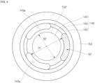
- FIGS. 3 and 4 are views illustrating inside and outside areas of an opening according to the position of a notch.
- the area of the opening 143a of the cap-up 140 may be divided into an inner area S1 positioned inside the notch 152 and an outer area S2 positioned outside the notch 152 based on the line where the notch 152 is formed.
- the opening 143a consists of only an outer area S2' without an inner area. That is, the proportion of the inner area of the opening 143a is 0%, and the proportion of the outer area S2' is 100%.
- the inner area S1 of the opening 143a may be determined by a diameter D1 of the terminal portion 141 of the cap-up 140 and a diameter D2 of the notch 152.
- the outer area S2 may be determined by the diameter D2 of the notch 152 and the diameter of the connecting portion 143.
- the diameter D2 of the notch 152 is larger than the diameter D1 of the terminal portion 141 and smaller than the diameter of the connecting portion 143.
- the inner area S1 may increase as a difference between the diameter D1 of the terminal portion 141 and the diameter D2 of the notch 152 increases.
- the wider the inner area S1 of the opening 143a, that is, the larger the diameter D2 of the notch 152 the faster the internal gas of the secondary battery 100 can be vented to the outside.
- the thermal diffusion test is a thermal safety evaluation method for evaluating the degree of influence that a thermal runaway event in one cell (secondary battery) may cause chain ignition by thermal diffusion propagation to adjacent cells, in an EV/ESS/E-bike, etc., which constitutes a module or pack by using multiple secondary batteries.
- each 10 secondary batteries each having a different proportion of the inner area occupied are prepared, and secondary batteries having the same inner area are formed into one battery pack.
- a thermal diffusion test was performed for each battery pack, and the results are shown in Table 1.
- Table 1 Classification Terminal portion diameter (mm) Notch diameter (mm) Outer area Inner area Total area (MM2) PPR result Proportion Proportion Comparative example 1 9 8 8.33 0 8.33 NG 10/10 100% 0% Comparative example 2 9 9 8.33 0 8.33 NG 6/10 100% 0% Comparative example 3 9 10 5.1 3.23 8.33 NG 4/10 61% 39% Comparative example 4 8.5 10 5.1 4.75 9.85 NG 2/10 52% 48%
- Comparative Example 1 when the notch diameter D2 is smaller than the terminal portion diameter D1 and the proportion of the inner area S1 is 0%, 10 secondary batteries were all ignited and assessed as NG.
- Comparative Example 1 since the notch diameter D2 is located inside the opening 143a, the gas vented through the notch 142 bumped into the terminal portion 141, making it difficult to vent the internal gas, and thus the side surface of secondary battery was torn to be ignited.
- Comparative Example 2 in which the notch diameter D2 and the terminal portion diameter D1 are the same, when the proportion of the inner area S1 is 0%, 6 out of 10 secondary batteries were ignited and assessed as NG.
- the proportion of the inner area S1 of the opening 143a is 55% or more, it can be seen that the gas generated inside the secondary battery 100 is quickly vented through the opening 143a to prevent thermal diffusion propagation to an adjacent secondary battery 100 due to generation of internal gas.
- the present invention relates to a secondary battery.
Landscapes
- Chemical & Material Sciences (AREA)
- Chemical Kinetics & Catalysis (AREA)
- Electrochemistry (AREA)
- General Chemical & Material Sciences (AREA)
- Gas Exhaust Devices For Batteries (AREA)
- Sealing Battery Cases Or Jackets (AREA)
Abstract
Description
- The present invention relates to a secondary battery.
- Unlike a primary battery that cannot be charged, a secondary battery is a rechargeable and dischargeable battery. A low-capacity secondary battery may be used for various portable small-sized electronic devices, such as a smartphone, a feature phone, a notebook computer, a digital camera, or a camcorder, and a high-capacity secondary battery is widely used as a power source for motor drives, such as those in hybrid vehicles or electric vehicles. These lithium ion secondary batteries may be classified into cylindrical, prismatic, and pouch-type secondary batteries in terms of shape.
- Specifically, a cylindrical lithium secondary battery generally includes a cylindrical electrode assembly, a cylindrical case to which the electrode assembly is coupled, an electrolyte injected into the case to allow movement of lithium ions, and a cap assembly that is coupled to one side of the case to prevent leakage of the electrolyte and prevents separation of the electrode assembly.
- The above information disclosed in this Background section is only for enhancement of understanding of the background of the invention and therefore it may contain information that does not constitute prior art.
- The present invention provides a secondary battery capable of improving safety by easily discharging internal gas.
- A secondary battery according to the present invention may include: an electrode assembly; a case in which the electrode assembly is accommodated; and a cap assembly which is coupled to the top of the case and comprises a cap-up having opening, a safety vent provided under the cap-up and having a notch to be ruptured at a predetermined pressure or higher, and a cap-down provided under the safety vent and electrically connected to the electrode assembly, wherein the notch is exposed through the opening.
- The area of the opening may include an inner area positioned inside the notch and an outer area positioned outside the notch based on the line where the notch is formed, and the inner area may be larger than the outer area.
- The inner area may be set to 55% or more of the total area of the opening.
- The cap-up may include a terminal portion protruding upward, a coupling portion positioned on an outer periphery of the terminal portion and coupled to the safety vent, and a connection portion connecting the terminal portion and the coupling portion, and the opening is formed in the connecting portion.
- An inner area of the opening may be determined by a diameter of the terminal portion and a diameter of the notch.
- An outer area of the opening may be determined by a diameter of the notch and a diameter of the connecting portion.
- The diameter of the notch may be larger than the diameter of the terminal portion and smaller than the diameter of the connecting portion.
- A gas vent hole located below the notch may be formed in the cap-down.
- A gasket disposed between the cap assembly and the case may be further included.
- In the secondary battery according to an embodiment of the present invention, a notch of a safety vent is exposed through an opening of a cap-up, and thus internal gas is rapidly vented, thereby improving safety.
-
-
FIG. 1 is a cross-sectional view of a secondary battery according to an embodiment of the present invention. -
FIG. 2 is a cross-sectional view of a cap assembly in a secondary battery according to an embodiment of the present invention. -
FIGS. 3 and4 are views illustrating inside and outside areas of an opening according to the position of a notch. - Hereinafter, a preferred embodiment of the present invention will be described in detail with reference to the accompanying drawings.
- Examples of the present invention are provided to more completely explain the present invention to those skilled in the art, and the following examples may be modified in various other forms. The present invention, however, may be embodied in many different forms and should not be construed as being limited to the example (or exemplary) embodiments set forth herein. Rather, these example embodiments are provided so that this invention will be thorough and complete and will convey the aspects and features of the present invention to those skilled in the art.
- In addition, in the accompanying drawings, sizes or thicknesses of various components are exaggerated for brevity and clarity, and like numbers refer to like elements throughout. As used herein, the term "and/or" includes any and all combinations of one or more of the associated listed items. In addition, it will be understood that when an element A is referred to as being "connected to" an element B, the element A can be directly connected to the element B or an intervening element C may be present therebetween such that the element A and the element B are indirectly connected to each other.
- The terminology used herein is for the purpose of describing particular embodiments only and is not intended to be limiting of the invention. As used herein, the singular forms are intended to include the plural forms as well, unless the context clearly indicates otherwise. It will be further understood that the terms that the terms "comprise or include" and/or "comprising or including," when used in this specification, specify the presence of stated features, numbers, steps, operations, elements, and/or components, but do not preclude the presence or addition of one or more other features, numbers, steps, operations, elements, components, and/or groups thereof.
- Spatially relative terms, such as "beneath," "below," "lower," "above," "upper," and the like, may be used herein for ease of description to describe one element or feature's relationship to another element(s) or feature(s) as illustrated in the figures. It will be understood that the spatially relative terms are intended to encompass different orientations of the device in use or operation in addition to the orientation depicted in the figures. For example, if the element or feature in the figures is turned over, elements described as "below" or "beneath" other elements or features would then be oriented "on" or "above" the other elements or features. Thus, the exemplary term "below" can encompass both an orientation of above and below.
-
FIG. 1 is a cross-sectional view of a secondary battery according to an embodiment of the present invention. - Referring to
FIG. 1 , asecondary battery 100 according to an embodiment of the present invention may include anelectrode assembly 110, acase 120, acap assembly 130, and agasket 190. - The
electrode assembly 110 includes afirst electrode 111, asecond electrode 112, and aseparator 113 interposed between thefirst electrode 111 and thesecond electrode 112. Theelectrode assembly 110 may be formed by winding a stack of thefirst electrode 111, theseparator 113, and thesecond electrode 112 in a jelly-roll shape. Here, thefirst electrode 111 may act as a positive electrode, and thesecond electrode 112 may act as a negative electrode. Afirst electrode tab 114 is connected to thecap assembly 130 at the top of theelectrode assembly 110, and asecond electrode tab 115 is connected to abottom plate 122 of thecase 120 at the bottom thereof. - The
first electrode 111 is formed by applying a first electrode active material such as a transition metal oxide to a first electrode current collector formed of a metal foil such as aluminum. A first electrode uncoated portion to which the first electrode active material is not applied is formed on thefirst electrode 111, and thefirst electrode tab 114 is attached to the first electrode uncoated portion. One end of thefirst electrode tab 114 is electrically connected to thefirst electrode 111, and the other end protrudes upward from theelectrode assembly 110 and is electrically connected to thecap assembly 130. - The
second electrode 112 is formed by applying a second electrode active material such as graphite or carbon to a second electrode current collector formed of a metal foil such as copper or nickel. An uncoated portion of the second electrode to which the second electrode active material is not applied is formed on thesecond electrode 112, and thesecond electrode tab 115 is attached to the uncoated portion of the second electrode. One end of thesecond electrode tab 115 is electrically connected to thesecond electrode 112, and the other end protrudes from the bottom of theelectrode assembly 110 and is electrically connected to thelower plate 122 of thecase 120. - The
separator 113 is positioned between thefirst electrode 111 and thesecond electrode 112 to prevent a short circuit and to enable the movement of lithium ions. Theseparator 113 may be made of polyethylene, polypropylene, or a composite film of polyethylene and polypropylene. - The
case 120 includes aside plate 121 which is a cylindrical body having a certain diameter so as to form a space in which theelectrode assembly 110 is accommodated, and alower plate 122 that seals a lower portion of theside plate 121. The top opening of thecase 120 is opened to seal after inserting theelectrode assembly 110 therein. In addition, abeading part 123 for preventing the movement of theelectrode assembly 110 is formed on the top of thecase 120. In addition, acrimping part 124 for fixing thecap assembly 130 and thegasket 190 is formed at the uppermost end of thecase 120. The crimpingpart 124 has agasket 190 interposed therebetween and is formed to press thecap assembly 130 to prevent separation of thecap assembly 130 and leakage of an electrolyte. -
FIG. 2 is a cross-sectional view of a cap assembly in a secondary battery according to an embodiment of the present invention. - Referring to
FIG. 2 , thecap assembly 130 includes a cap-up 140, asafety vent 150, aninsulator 160, and a cap-down 170. - The cap-
up 140 is formed as a circular plate body and may include aterminal portion 141 convexly formed upward in the center, acoupling portion 142 located on the outer periphery of theterminal portion 141, and a connectingportion 143 connecting theterminal portion 141 and thecoupling portion 142. - The
terminal portion 141 protrudes upward compared to thecoupling portion 142 and serves as a terminal electrically connected to an external circuit. Theterminal portion 141 is electrically connected to thefirst electrode tab 114 and may act as, for example, a positive electrode. Thecoupling portion 142 is located on the outer periphery of theterminal portion 141, and thesafety vent 150 is coupled to thecoupling portion 142. Avent extending portion 153 of thesafety vent 150 is coupled to an upper portion of thecoupling portion 142. The connectingportion 143 connects theterminal portion 141 and thecoupling portion 142, and anopening 143a is formed in the connectingportion 143. Theopening 143a may include a plurality of openings formed in the connectingportion 143 and may provide a path through which gas generated inside thecase 120 can be vented. In addition, a portion of theopening 143a may extend to theterminal portion 141 and thecoupling portion 142. In some examples, when theopening 143a extends to theterminal portion 141, the diameter of theterminal portion 141 decreases and the area occupied by theopening 143a increases. - The
safety vent 150 is formed as a circular plate body corresponding to the cap-up 140 and coupled to the lower portion of the cap-up 140. Aprotrusion 151 protruding downward is formed at the center of thesafety vent 150. Thesafety vent 150 is electrically connected to a sub-plate 175 fixed to the lower surface of the cap-down 170 by using theprotrusion 151 passing through a through-hole 171 of the cap-down 170. Here, theprotrusion 151 of thesafety vent 150 and the sub-plate 175 may be welded by laser welding, ultrasonic welding, resistance welding, or an equivalent method thereof. - In addition, a
notch 152 that guides rupture of thesafety vent 150 is formed on the outer periphery of theprotrusion 151. Thesafety vent 150 vents internal gas while blocking current when an abnormal internal pressure is generated inside thecase 120. When the internal pressure of thecase 120 exceeds an operating pressure of thesafety vent 150, thesafety vent 150 is electrically separated from the sub-plate 175 while theprotrusion 151 rises upward by the gas vented through agas vent hole 172 of the cap-down 170. Here, the sub-plate 175 is electrically separated from thesafety vent 150 as the welded portion of theprotrusion 151 is torn. In addition, in thesafety vent 150 , when the internal pressure of thecase 120 exceeds a rupture pressure higher than the operating pressure of thesafety vent 150, thenotch 152 is broken, thereby preventing thesecondary battery 100 from exploding. Thesafety vent 150 may be formed of aluminum (Al). - The
notch 152 may be formed in a circular shape along the outer periphery of thesafety vent 150. In addition, thenotch 152 may be located at a position corresponding to theopening 143a formed in the cap-up 140, that is, below theopening 143a, and exposed to the outside through theopening 143a. That is, thenotch 152 may be visually identified from the outside of thesecondary battery 100 through theopening 143a. In addition, since theopening 143a is positioned above thenotch 152, when thenotch 152 is broken by the internal gas, the gas can be rapidly vented through theopening 143a. - The
safety vent 150 is installed in close contact with thecoupling portion 142 at the bottom of the cap-up 140. In addition, the edge of thesafety vent 150 surrounds the cap-up 140 and extends to the top of the cap-up 140. Here, a portion extending upward from the cap-up 140 is defined as avent extending portion 153. In some examples, thesafety vent 150 may be fixed to the cap-up 140 by welding an upper portion of thevent extending portion 153. - The
insulator 160 is interposed between thesafety vent 150 and the cap-down 170 and insulates thesafety vent 150 and the cap-down 170 from each other. Specifically, theinsulator 160 is formed in a ring shape and is interposed between the outer periphery of thesafety vent 150 and the outer periphery of the cap-down 170. Theinsulator 160 may be made of a resin material such as polyethylene (PE), polypropylene (PP), or polyethylene terephthalate (PET). - The cap-down 170 is formed as a circular plate body. The through
hole 171 is formed at the center of the cap-down 170, and theprotrusion 151 of thesafety vent 150 passes through the throughhole 171. In addition, agas vent hole 172 is formed at one side of the cap-down 170, and the sub-plate 175 is coupled to the lower portion of the cap-down 170. Thegas vent hole 172 serves to vent internal gas when excessive internal pressure is generated inside thecase 120. Here, theprotrusion 151 of thesafety vent 150 is raised by the gas vented through thegas vent hole 172, and theprotrusion 151 may be separated from the sub-plate 175. The sub-plate 175 is welded between theprotrusion 151 of thesafety vent 150 passing through the throughhole 171 of the cap-down 170 and thefirst electrode tab 114. Accordingly, the sub-plate 175 may electrically connect thefirst electrode tab 114 and thesafety vent 150. In some examples, thegas vent hole 172 may be formed at a position corresponding to a portion of thesafety vent 150 where thenotch 152 is formed. Accordingly, a path through which gas is vented may be shortened, thereby facilitating gas venting. - The
gasket 190 is installed in the top opening of thecase 120. That is, thegasket 190 is tightly assembled between the outer periphery of the cap-up 140 and thesafety vent 150 and the top opening of thecase 120. Thegasket 190 may be made of a resin material such as polyethylene (PE), polypropylene (PP), or polyethylene terephthalate (PET). Thegasket 190 may electrically insulate thecase 120 and thecap assembly 130 from each other. -
FIGS. 3 and4 are views illustrating inside and outside areas of an opening according to the position of a notch. - Referring to
FIG. 3 , in thesecondary battery 100 according to the present invention, since thenotch 152 of thesafety vent 150 is exposed through theopening 143a of the cap-up 140, the area of theopening 143a of the cap-up 140 may be divided into an inner area S1 positioned inside thenotch 152 and an outer area S2 positioned outside thenotch 152 based on the line where thenotch 152 is formed. In some examples, as shown inFIG. 4 , when thenotch 152 is positioned below theterminal portion 141 without being exposed through theopening 143a, theopening 143a consists of only an outer area S2' without an inner area. That is, the proportion of the inner area of theopening 143a is 0%, and the proportion of the outer area S2' is 100%. - Referring back to
FIG. 3 , the inner area S1 of theopening 143a may be determined by a diameter D1 of theterminal portion 141 of the cap-up 140 and a diameter D2 of thenotch 152. The outer area S2 may be determined by the diameter D2 of thenotch 152 and the diameter of the connectingportion 143. In the present invention, the diameter D2 of thenotch 152 is larger than the diameter D1 of theterminal portion 141 and smaller than the diameter of the connectingportion 143. - In some examples, the inner area S1 may increase as a difference between the diameter D1 of the
terminal portion 141 and the diameter D2 of thenotch 152 increases. In addition, the wider the inner area S1 of theopening 143a, that is, the larger the diameter D2 of thenotch 152, the faster the internal gas of thesecondary battery 100 can be vented to the outside. - In order to evaluate the safety of the
secondary battery 100 according to the proportions of the inner area S1 and the outer area S2 of theopening 143a, a thermal diffusion test (passive propagation resistance test (PPR test)) was performed. The thermal diffusion test is a thermal safety evaluation method for evaluating the degree of influence that a thermal runaway event in one cell (secondary battery) may cause chain ignition by thermal diffusion propagation to adjacent cells, in an EV/ESS/E-bike, etc., which constitutes a module or pack by using multiple secondary batteries. - First, each 10 secondary batteries each having a different proportion of the inner area occupied are prepared, and secondary batteries having the same inner area are formed into one battery pack. Next, a thermal diffusion test was performed for each battery pack, and the results are shown in Table 1.
[Table 1] Classification Terminal portion diameter (mm) Notch diameter (mm) Outer area Inner area Total area (MM2) PPR result Proportion Proportion Comparative example 1 9 8 8.33 0 8.33 NG 10/10 100% 0% Comparative example 2 9 9 8.33 0 8.33 NG 6/10 100% 0% Comparative example 3 9 10 5.1 3.23 8.33 NG 4/10 61% 39% Comparative example 4 8.5 10 5.1 4.75 9.85 NG 2/1052% 48% Example 1 8 10 5.1 6.19 11.29 OK 10/10 45% 55% Example 2 7.5 10 5.1 7.38 12.48 OK 10/10 41% 59% Example 3 6.5 10 5.1 9.49 14.59 OK 10/10 35% 65% Example 4 4.85 10 5.1 11.41 16.51 OK 10/10 31% 69% - First, referring to Comparative Example 1, when the notch diameter D2 is smaller than the terminal portion diameter D1 and the proportion of the inner area S1 is 0%, 10 secondary batteries were all ignited and assessed as NG. In Comparative Example 1, since the notch diameter D2 is located inside the
opening 143a, the gas vented through thenotch 142 bumped into theterminal portion 141, making it difficult to vent the internal gas, and thus the side surface of secondary battery was torn to be ignited. In Comparative Example 2 in which the notch diameter D2 and the terminal portion diameter D1 are the same, when the proportion of the inner area S1 is 0%, 6 out of 10 secondary batteries were ignited and assessed as NG. In Comparative Example 3, when the notch diameter D2 is larger than the terminal portion diameter D1 and the proportion of the inner area S1 is 39%, 4 out of 10 secondary batteries were ignited and assessed as NG. In Comparative Example 4, when the notch diameter D2 is larger than the terminal portion diameter D1 and the proportion of the inner area S1 is 48%, 2 out of 10 secondary batteries were ignited and assessed as NG. next, referring to Example 1, when the notch diameter D2 is larger than the terminal portion diameter D1 and the proportion of the inner area S1 is 55%, 10 secondary batteries were all ignited and assessed as OK. In Examples 2 to 4, when the notch diameter D2 is larger than the terminal portion diameter D1 and the proportions of the inner area S1 are 59%, 65%, and 69%, respectively, 10 secondary batteries were all ignited and assessed as OK. - As described above, if the proportion of the inner area S1 of the
opening 143a is 55% or more, it can be seen that the gas generated inside thesecondary battery 100 is quickly vented through theopening 143a to prevent thermal diffusion propagation to an adjacentsecondary battery 100 due to generation of internal gas. - While the foregoing embodiment has been provided for carrying out the secondary battery according to the present invention, it should be understood that the embodiment described herein should be considered in a descriptive sense only and not for purposes of limitation, and various changes in form and details may be made therein without departing from the spirit and scope of the invention as defined by the following claims.
- The present invention relates to a secondary battery.
Claims (9)
- A secondary battery comprising:an electrode assembly;a case in which the electrode assembly is accommodated; anda cap assembly which is coupled to the top of the case and comprises a cap-up having opening, a safety vent provided under the cap-up and having a notch to be ruptured at a predetermined pressure or higher, and a cap-down provided under the safety vent and electrically connected to the electrode assembly,wherein the notch is exposed through the opening.
- The secondary battery of claim 1, wherein the area of the opening includes an inner area positioned inside the notch and an outer area positioned outside the notch based on the line where the notch is formed, and the inner area is larger than the outer area.
- The secondary battery of claim 2, wherein the inner area is set to 55% or more of the total area of the opening.
- The secondary battery of claim 2, wherein the cap-up includes a terminal portion protruding upward, a coupling portion positioned on an outer periphery of the terminal portion and coupled to the safety vent, and a connection portion connecting the terminal portion and the coupling portion, and the opening is formed in the connecting portion.
- The secondary battery of claim 4, wherein an inner area of the opening is determined by a diameter of the terminal portion and a diameter of the notch.
- The secondary battery of claim 4, wherein an outer area of the opening is determined by a diameter of the notch and a diameter of the connecting portion.
- The secondary battery of claim 4, wherein the diameter of the notch is larger than the diameter of the terminal portion and smaller than the diameter of the connecting portion.
- The secondary battery of claim 1, wherein a gas vent hole located below the notch is formed in the cap-down.
- The secondary battery of claim 1, further comprising a gasket positioned between the cap assembly and the case.
Priority Applications (1)
| Application Number | Priority Date | Filing Date | Title |
|---|---|---|---|
| EP25216470.2A EP4697466A3 (en) | 2020-10-26 | 2021-09-16 | Secondary battery |
Applications Claiming Priority (2)
| Application Number | Priority Date | Filing Date | Title |
|---|---|---|---|
| KR1020200139612A KR20220055306A (en) | 2020-10-26 | 2020-10-26 | Secondary Battery |
| PCT/KR2021/012690 WO2022092566A1 (en) | 2020-10-26 | 2021-09-16 | Secondary battery |
Related Child Applications (2)
| Application Number | Title | Priority Date | Filing Date |
|---|---|---|---|
| EP25216470.2A Division EP4697466A3 (en) | 2020-10-26 | 2021-09-16 | Secondary battery |
| EP25216470.2A Division-Into EP4697466A3 (en) | 2020-10-26 | 2021-09-16 | Secondary battery |
Publications (3)
| Publication Number | Publication Date |
|---|---|
| EP4235929A1 true EP4235929A1 (en) | 2023-08-30 |
| EP4235929A4 EP4235929A4 (en) | 2025-06-25 |
| EP4235929B1 EP4235929B1 (en) | 2026-03-18 |
Family
ID=81382912
Family Applications (2)
| Application Number | Title | Priority Date | Filing Date |
|---|---|---|---|
| EP25216470.2A Pending EP4697466A3 (en) | 2020-10-26 | 2021-09-16 | Secondary battery |
| EP21886560.8A Active EP4235929B1 (en) | 2020-10-26 | 2021-09-16 | Secondary battery |
Family Applications Before (1)
| Application Number | Title | Priority Date | Filing Date |
|---|---|---|---|
| EP25216470.2A Pending EP4697466A3 (en) | 2020-10-26 | 2021-09-16 | Secondary battery |
Country Status (5)
| Country | Link |
|---|---|
| US (1) | US20230378595A1 (en) |
| EP (2) | EP4697466A3 (en) |
| KR (1) | KR20220055306A (en) |
| CN (1) | CN116529940A (en) |
| WO (1) | WO2022092566A1 (en) |
Families Citing this family (3)
| Publication number | Priority date | Publication date | Assignee | Title |
|---|---|---|---|---|
| SE2251552A1 (en) * | 2022-12-22 | 2024-06-23 | Northvolt Ab | A ventilated terminal arrangement for a cylindrical secondary cell |
| SE2251549A1 (en) * | 2022-12-22 | 2024-06-23 | Northvolt Ab | A ventilated terminal part for a cylindrical secondary cell |
| SE2251550A1 (en) * | 2022-12-22 | 2024-06-23 | Northvolt Ab | An aligned ventilated terminal arrangement for a cylindrical secondary cell |
Family Cites Families (9)
| Publication number | Priority date | Publication date | Assignee | Title |
|---|---|---|---|---|
| KR100978092B1 (en) * | 2008-05-30 | 2010-08-25 | 삼성에스디아이 주식회사 | Cap assembly and secondary battery having the same |
| KR100966549B1 (en) * | 2008-10-14 | 2010-06-29 | 주식회사 엘지화학 | Cap assembly with improved safety and cylindrical secondary battery containing same |
| US8597809B2 (en) * | 2010-02-18 | 2013-12-03 | Samsung Sdi Co., Ltd. | Rechargeable battery |
| KR101184403B1 (en) * | 2010-10-21 | 2012-09-19 | 주식회사 엘지화학 | Cap assembly and secondary battery using the same |
| KR101523064B1 (en) * | 2013-02-26 | 2015-05-26 | 주식회사 엘지화학 | Cap assembly and secondary battery including the same |
| KR102161629B1 (en) * | 2014-02-20 | 2020-10-05 | 삼성에스디아이 주식회사 | Cap assembly and secondary battery comprising the same |
| KR101948620B1 (en) * | 2015-06-05 | 2019-02-15 | 주식회사 엘지화학 | A cap assembly for a secondary battery |
| KR102421803B1 (en) * | 2018-05-03 | 2022-07-15 | 주식회사 엘지에너지솔루션 | Cap assembly for rechargeable battery and rechargeable batter comprising the same |
| KR102871159B1 (en) * | 2019-07-08 | 2025-10-16 | 삼성에스디아이 주식회사 | Secondary battery |
-
2020
- 2020-10-26 KR KR1020200139612A patent/KR20220055306A/en active Pending
-
2021
- 2021-09-16 WO PCT/KR2021/012690 patent/WO2022092566A1/en not_active Ceased
- 2021-09-16 US US18/247,734 patent/US20230378595A1/en active Pending
- 2021-09-16 EP EP25216470.2A patent/EP4697466A3/en active Pending
- 2021-09-16 CN CN202180073208.4A patent/CN116529940A/en active Pending
- 2021-09-16 EP EP21886560.8A patent/EP4235929B1/en active Active
Also Published As
| Publication number | Publication date |
|---|---|
| US20230378595A1 (en) | 2023-11-23 |
| EP4697466A2 (en) | 2026-02-18 |
| EP4235929A4 (en) | 2025-06-25 |
| WO2022092566A1 (en) | 2022-05-05 |
| EP4697466A3 (en) | 2026-02-25 |
| KR20220055306A (en) | 2022-05-03 |
| EP4235929B1 (en) | 2026-03-18 |
| CN116529940A (en) | 2023-08-01 |
Similar Documents
| Publication | Publication Date | Title |
|---|---|---|
| CN114175380B (en) | Secondary battery | |
| US12394860B2 (en) | Secondary battery | |
| US20090117459A1 (en) | Secondary battery and method of manufacturing the same | |
| US20100297484A1 (en) | Rechargeable battery | |
| KR102389409B1 (en) | The Apparatus For Venting | |
| EP4235929B1 (en) | Secondary battery | |
| US20230238616A1 (en) | Secondary battery | |
| KR102761907B1 (en) | Secondary Battery | |
| KR102323809B1 (en) | The Apparatus For Venting And The Method For Manufacturing Thereof | |
| US20230223622A1 (en) | Secondary battery | |
| US20230223643A1 (en) | Secondary battery | |
| CN100372164C (en) | Secondary battery, its cap assembly and method of installing safety valve therefor | |
| EP4231428A1 (en) | Secondary battery | |
| EP4369480A1 (en) | Secondary battery | |
| KR102935966B1 (en) | Secondary battery | |
| US12476310B2 (en) | Secondary battery and manufacturing method of secondary battery | |
| US20230335836A1 (en) | Secondary battery | |
| US20240145853A1 (en) | Secondary battery | |
| US20230238503A1 (en) | Secondary battery | |
| KR20250066633A (en) | Secondary Battery | |
| KR20260014376A (en) | Secondary battery and method for manufacturing same |
Legal Events
| Date | Code | Title | Description |
|---|---|---|---|
| STAA | Information on the status of an ep patent application or granted ep patent |
Free format text: STATUS: THE INTERNATIONAL PUBLICATION HAS BEEN MADE |
|
| PUAI | Public reference made under article 153(3) epc to a published international application that has entered the european phase |
Free format text: ORIGINAL CODE: 0009012 |
|
| STAA | Information on the status of an ep patent application or granted ep patent |
Free format text: STATUS: REQUEST FOR EXAMINATION WAS MADE |
|
| 17P | Request for examination filed |
Effective date: 20230330 |
|
| AK | Designated contracting states |
Kind code of ref document: A1 Designated state(s): AL AT BE BG CH CY CZ DE DK EE ES FI FR GB GR HR HU IE IS IT LI LT LU LV MC MK MT NL NO PL PT RO RS SE SI SK SM TR |
|
| DAV | Request for validation of the european patent (deleted) | ||
| DAX | Request for extension of the european patent (deleted) | ||
| TPAC | Observations filed by third parties |
Free format text: ORIGINAL CODE: EPIDOSNTIPA |
|
| A4 | Supplementary search report drawn up and despatched |
Effective date: 20250528 |
|
| RIC1 | Information provided on ipc code assigned before grant |
Ipc: H01M 50/559 20210101ALI20250522BHEP Ipc: H01M 50/186 20210101ALI20250522BHEP Ipc: H01M 50/531 20210101ALI20250522BHEP Ipc: H01M 50/528 20210101ALI20250522BHEP Ipc: H01M 50/107 20210101ALI20250522BHEP Ipc: H01M 50/152 20210101ALI20250522BHEP Ipc: H01M 50/342 20210101AFI20250522BHEP |
|
| REG | Reference to a national code |
Ref country code: DE Ref legal event code: R079 Free format text: PREVIOUS MAIN CLASS: H01M0050342000 Ipc: H01M0050107000 Ref country code: DE Ref legal event code: R079 Ref document number: 602021050366 Country of ref document: DE Free format text: PREVIOUS MAIN CLASS: H01M0050342000 Ipc: H01M0050107000 |
|
| GRAP | Despatch of communication of intention to grant a patent |
Free format text: ORIGINAL CODE: EPIDOSNIGR1 |
|
| STAA | Information on the status of an ep patent application or granted ep patent |
Free format text: STATUS: GRANT OF PATENT IS INTENDED |
|
| RIC1 | Information provided on ipc code assigned before grant |
Ipc: H01M 50/107 20210101AFI20250930BHEP Ipc: H01M 50/152 20210101ALI20250930BHEP Ipc: H01M 50/528 20210101ALI20250930BHEP Ipc: H01M 50/559 20210101ALI20250930BHEP Ipc: H01M 50/342 20210101ALI20250930BHEP Ipc: H01M 50/531 20210101ALI20250930BHEP Ipc: H01M 50/186 20210101ALI20250930BHEP |
|
| INTG | Intention to grant announced |
Effective date: 20251009 |
|
| GRAS | Grant fee paid |
Free format text: ORIGINAL CODE: EPIDOSNIGR3 |
|
| GRAA | (expected) grant |
Free format text: ORIGINAL CODE: 0009210 |
|
| STAA | Information on the status of an ep patent application or granted ep patent |
Free format text: STATUS: THE PATENT HAS BEEN GRANTED |
|
| AK | Designated contracting states |
Kind code of ref document: B1 Designated state(s): AL AT BE BG CH CY CZ DE DK EE ES FI FR GB GR HR HU IE IS IT LI LT LU LV MC MK MT NL NO PL PT RO RS SE SI SK SM TR |
|
| REG | Reference to a national code |
Ref country code: CH Ref legal event code: F10 Free format text: ST27 STATUS EVENT CODE: U-0-0-F10-F00 (AS PROVIDED BY THE NATIONAL OFFICE) Effective date: 20260318 Ref country code: GB Ref legal event code: FG4D |
|
| REG | Reference to a national code |
Ref country code: IE Ref legal event code: FG4D |
|
| REG | Reference to a national code |
Ref country code: DE Ref legal event code: R096 Ref document number: 602021050366 Country of ref document: DE |