EP4235924A1 - Battery module and battery pack comprising same - Google Patents
Battery module and battery pack comprising same Download PDFInfo
- Publication number
- EP4235924A1 EP4235924A1 EP22887434.3A EP22887434A EP4235924A1 EP 4235924 A1 EP4235924 A1 EP 4235924A1 EP 22887434 A EP22887434 A EP 22887434A EP 4235924 A1 EP4235924 A1 EP 4235924A1
- Authority
- EP
- European Patent Office
- Prior art keywords
- battery
- battery cell
- cell assembly
- module
- stacked
- Prior art date
- Legal status (The legal status is an assumption and is not a legal conclusion. Google has not performed a legal analysis and makes no representation as to the accuracy of the status listed.)
- Granted
Links
Images




Classifications
-
- H—ELECTRICITY
- H01—ELECTRIC ELEMENTS
- H01M—PROCESSES OR MEANS, e.g. BATTERIES, FOR THE DIRECT CONVERSION OF CHEMICAL ENERGY INTO ELECTRICAL ENERGY
- H01M50/00—Constructional details or processes of manufacture of the non-active parts of electrochemical cells other than fuel cells, e.g. hybrid cells
- H01M50/20—Mountings; Secondary casings or frames; Racks, modules or packs; Suspension devices; Shock absorbers; Transport or carrying devices; Holders
- H01M50/204—Racks, modules or packs for multiple batteries or multiple cells
- H01M50/207—Racks, modules or packs for multiple batteries or multiple cells characterised by their shape
- H01M50/211—Racks, modules or packs for multiple batteries or multiple cells characterised by their shape adapted for pouch cells
-
- H—ELECTRICITY
- H01—ELECTRIC ELEMENTS
- H01M—PROCESSES OR MEANS, e.g. BATTERIES, FOR THE DIRECT CONVERSION OF CHEMICAL ENERGY INTO ELECTRICAL ENERGY
- H01M50/00—Constructional details or processes of manufacture of the non-active parts of electrochemical cells other than fuel cells, e.g. hybrid cells
- H01M50/20—Mountings; Secondary casings or frames; Racks, modules or packs; Suspension devices; Shock absorbers; Transport or carrying devices; Holders
- H01M50/204—Racks, modules or packs for multiple batteries or multiple cells
-
- H—ELECTRICITY
- H01—ELECTRIC ELEMENTS
- H01M—PROCESSES OR MEANS, e.g. BATTERIES, FOR THE DIRECT CONVERSION OF CHEMICAL ENERGY INTO ELECTRICAL ENERGY
- H01M50/00—Constructional details or processes of manufacture of the non-active parts of electrochemical cells other than fuel cells, e.g. hybrid cells
- H01M50/20—Mountings; Secondary casings or frames; Racks, modules or packs; Suspension devices; Shock absorbers; Transport or carrying devices; Holders
- H01M50/258—Modular batteries; Casings provided with means for assembling
-
- H—ELECTRICITY
- H01—ELECTRIC ELEMENTS
- H01M—PROCESSES OR MEANS, e.g. BATTERIES, FOR THE DIRECT CONVERSION OF CHEMICAL ENERGY INTO ELECTRICAL ENERGY
- H01M50/00—Constructional details or processes of manufacture of the non-active parts of electrochemical cells other than fuel cells, e.g. hybrid cells
- H01M50/20—Mountings; Secondary casings or frames; Racks, modules or packs; Suspension devices; Shock absorbers; Transport or carrying devices; Holders
- H01M50/289—Mountings; Secondary casings or frames; Racks, modules or packs; Suspension devices; Shock absorbers; Transport or carrying devices; Holders characterised by spacing elements or positioning means within frames, racks or packs
-
- H—ELECTRICITY
- H01—ELECTRIC ELEMENTS
- H01M—PROCESSES OR MEANS, e.g. BATTERIES, FOR THE DIRECT CONVERSION OF CHEMICAL ENERGY INTO ELECTRICAL ENERGY
- H01M50/00—Constructional details or processes of manufacture of the non-active parts of electrochemical cells other than fuel cells, e.g. hybrid cells
- H01M50/50—Current conducting connections for cells or batteries
- H01M50/502—Interconnectors for connecting terminals of adjacent batteries; Interconnectors for connecting cells outside a battery casing
-
- H—ELECTRICITY
- H01—ELECTRIC ELEMENTS
- H01M—PROCESSES OR MEANS, e.g. BATTERIES, FOR THE DIRECT CONVERSION OF CHEMICAL ENERGY INTO ELECTRICAL ENERGY
- H01M50/00—Constructional details or processes of manufacture of the non-active parts of electrochemical cells other than fuel cells, e.g. hybrid cells
- H01M50/50—Current conducting connections for cells or batteries
- H01M50/502—Interconnectors for connecting terminals of adjacent batteries; Interconnectors for connecting cells outside a battery casing
- H01M50/503—Interconnectors for connecting terminals of adjacent batteries; Interconnectors for connecting cells outside a battery casing characterised by the shape of the interconnectors
-
- H—ELECTRICITY
- H01—ELECTRIC ELEMENTS
- H01M—PROCESSES OR MEANS, e.g. BATTERIES, FOR THE DIRECT CONVERSION OF CHEMICAL ENERGY INTO ELECTRICAL ENERGY
- H01M50/00—Constructional details or processes of manufacture of the non-active parts of electrochemical cells other than fuel cells, e.g. hybrid cells
- H01M50/50—Current conducting connections for cells or batteries
- H01M50/502—Interconnectors for connecting terminals of adjacent batteries; Interconnectors for connecting cells outside a battery casing
- H01M50/507—Interconnectors for connecting terminals of adjacent batteries; Interconnectors for connecting cells outside a battery casing comprising an arrangement of two or more busbars within a container structure, e.g. busbar modules
-
- Y—GENERAL TAGGING OF NEW TECHNOLOGICAL DEVELOPMENTS; GENERAL TAGGING OF CROSS-SECTIONAL TECHNOLOGIES SPANNING OVER SEVERAL SECTIONS OF THE IPC; TECHNICAL SUBJECTS COVERED BY FORMER USPC CROSS-REFERENCE ART COLLECTIONS [XRACs] AND DIGESTS
- Y02—TECHNOLOGIES OR APPLICATIONS FOR MITIGATION OR ADAPTATION AGAINST CLIMATE CHANGE
- Y02E—REDUCTION OF GREENHOUSE GAS [GHG] EMISSIONS, RELATED TO ENERGY GENERATION, TRANSMISSION OR DISTRIBUTION
- Y02E60/00—Enabling technologies; Technologies with a potential or indirect contribution to GHG emissions mitigation
- Y02E60/10—Energy storage using batteries
Definitions
- the present invention relates to a battery module and a battery pack including the same.
- a battery module and a battery pack that can prevent an internal short circuit from being electrically formed due to a simple electrical connection structure.
- secondary batteries capable of charging and discharging have been widely used as energy sources of wireless mobile devices.
- the secondary battery has attracted attention as an energy source of electric vehicles, hybrid electric vehicles, and the like, which are proposed as a solution for air pollution and the like of existing gasoline vehicles and diesel vehicles using fossil fuels. Accordingly, the types of applications using the secondary battery have diversified due to the advantages of the secondary battery, and it is expected that the secondary battery will be applied to many fields and products in the future.
- ESS Energy Storage System
- a battery module accommodating a plurality of secondary batteries electrically connected in series or in parallel and a battery pack composed of the battery modules.
- Such a battery module or battery pack includes an external housing made of a metal material to protect a plurality of secondary batteries from external impacts or receive and store the secondary batteries.
- FIG. 1 is a plan view ( FIG. 1(a) ) showing an example of a structure of a battery module 100' having expandability proposed by the present applicant, and a plan view ( FIG. 1(b) ) of a battery module stack 1000' configured by stacking the battery modules 100', and FIG. 2 is a schematic diagram showing an electrical path of the battery module stack 1000' composed of the battery modules of FIG. 1 .
- the present applicant has invented a battery module 100' accommodating an electrode assembly composed of a first battery cell assembly 10' in which a plurality of battery cells 1' are stacked in the battery cell thickness direction, and a second battery cell assembly 20' facing the first battery cell assembly 10' in the battery cell longitudinal direction and comprising a plurality of battery cells in the battery cell thickness direction in the same way as the first battery cell assembly 10', in a rectangular parallelepiped shape module case 30' elongated in the longitudinal direction.
- Such a battery module 100' accommodates a relatively small number of battery cells in each module case 30', and stacks the battery modules in the longitudinal direction or the thickness direction of the battery cell like Lego blocks, so that a battery pack may be freely configured in consideration of the space where the battery module 100' is installed or the installation space of the battery pack.
- the battery module 100' proposed by the present applicant can manufacture various types of battery packs based on the stacking (designing) method, it can be referred to as an expandable battery module.
- the expandable battery modules proposed so far had a structure in which the first and second battery cell assemblies 10', 20' facing each other in the longitudinal direction are electrically connected to each other.
- the battery cells in the lower two rows of the first and second battery cell assemblies 10', 20' are not connected to each other, but the battery cells in the upper two rows of the first and second battery cell assemblies 10', 20' are electrically connected to each other (refer to the electricity connecting part of A in FIG. 1 ).
- the expandable battery module with this electrical connection structure has the following problems.
- the electrical connection structure of the battery module itself becomes complicated, and as a result, in the case of stacking a battery module including the first and second battery cell assemblies 10', 20', a total of three lines (a, b, c) of high voltage busbars are required as shown in FIG. 1(b) to electrically connect between the battery cell assemblies of each battery module.
- thermal runaway (hereinafter referred to as ⁇ TR' for short) occurs in some of the battery cells of the stacked battery module 100', there has been a problem in that an internal short circuit is formed. That is, in FIG. 2(a) , adjacent battery modules are only electrically connected to each other by the above-described high voltage busbars, and the battery cells between each module should not be directly connected to each other.
- thermal runaway occurs in one battery cell 1'
- the battery cell 1' is melted and comes into contact with the module case 30', and thermal runaway is propagated to the module case 30' of the adjacent module and the battery cell' located inside the module case. Accordingly, as show in FIG.
- thermal runaway proceeds along the stacking direction of the battery modules, so that thermal runaway propagates between the first battery cell assemblies 10' of the left battery modules.
- first battery cell assembly 10' of the battery modules is electrically connected to the second battery cell assembly 20' of each battery module, respectively, even the second battery cell assembly 20' becomes shortcircuited, thereby an electrical internal short circuit is formed in the entire battery module 100' or the battery module stack 1000' (see FIG. 2(c) ).
- gas is rapidly generated and overheated, thereby danger of explosion of a battery pack increases.
- Patent Document 1 Korean Patent Publication No. 10-2020-0131500
- the present invention was made to solve the above problems, and it is directed to provide a battery module and a battery pack that can simplify the electrical connection structure by excluding the electrical connection between two battery cell assemblies constituting the expandable module and can prevent the occurrence of an internal short circuit.
- the battery module according to the present invention for solving the above problems includes: a first battery cell assembly in which a plurality of battery cells are stacked in the thickness direction of the battery cell; a second battery cell assembly in which each battery cell arranged in a row in the longitudinal direction of the battery cell with respect to each battery cell stacked in the first battery cell assembly is stacked in the thickness direction of the battery cell in the same number as the number of battery cells stacked in the first battery cell assembly; and a module case accommodating the first and second battery cell assembly, wherein the battery cells of the first battery cell assembly are electrically connected to each other, and the battery cells of the second battery cell assembly are electrically connected to each other, but the battery cells are not electrically connected to each other between the first and second battery cell assemblies.
- the battery cells constituting the first battery cell assembly and the second battery cell assembly may be pouch cells from which electrode leads of different polarities are protruded from both ends.
- the number of stacked battery cells of the first battery cell assembly and the second battery cell assembly is an even number.
- the battery cells included in the first battery cell assembly and the second battery cell assembly are electrically connected to the electrode leads of adjacent battery cells so as to form an electrical path connected in a zigzag direction, respectively, and both ends of the electrical path may be electrode leads that are protruding toward the gap between the first and second battery cell assemblies among the electrode leads at both ends of the battery cells included in the first and second battery cell assemblies.
- the electrode leads of the battery cells included in the first and second battery cell assemblies which are each protruding toward the gap between the first and second battery cell assemblies, have opposite polarities.
- a terminal busbar may be coupled to the electrode leads respectively protruding from the first and second battery cell assemblies toward the gap between the first and second battery cell assemblies.
- electrode leads of adjacent battery cells are coupled through an inter busbar or directly coupled by being bent to each other so as to form an electrical path connected in the zigzag direction.
- a first partition extending in the battery cell thickness direction may be installed between the first battery cell assembly and the second battery cell assembly.
- a second partition extending in the longitudinal direction of the module case may be provided in the middle part of the battery cells stacked in the thickness direction of the first battery cell assembly and the second battery cell assembly.
- the battery pack includes a battery module stack in which a plurality of the battery modules are stacked in the thickness direction of the battery cells.
- the first battery cell assemblies of battery modules stacked in the thickness direction are electrically connected to each other to constitute a first electric block
- the second battery cell assemblies are electrically connected to each other to constitute a second electric block. Except for the first and second battery cell assemblies of battery modules stacked at the top of the battery module stack, each of the first and second battery cell assemblies constituting the first electric block and the second electric block is not electrically connected to each other.
- the first and second battery cell assemblies of battery modules stacked at the top of the battery module stack are electrically connected by a high voltage busbar to electrically connect the first electric block and the second electric block.
- a first high voltage busbar electrically connecting the first battery cell assemblies to each other and a second high voltage busbar electrically connecting the second battery cell assemblies to each other may be installed on the battery module in the stacking direction of the battery module in order to constitute the first electric block and the second electric block.
- the first high voltage busbar is connected to a terminal busbar coupled to an electrode lead of a battery cell protruding from the first battery cell assembly toward the gap between the first battery cell assembly and the second battery cell assembly of the battery module
- the second high voltage busbar is connected to a terminal busbar coupled to an electrode lead of a battery cell protruding from the second battery cell assembly toward the gap between the first battery cell assembly and the second battery cell assembly of the battery module.
- the electrical connection structure of the first and second battery cell assemblies is a 1PNS structure, and N is an even number.
- the electrical connection structure of an expandable battery module including two battery cell assemblies and a battery pack formed by stacking the battery modules can be greatly simplified.
- each battery cell assembly independently constitutes an electric circuit, the formation of an internal short circuit can be delayed as much as possible or controlled to be formed in order. Accordingly, the safety of the battery pack can be further improved.
- a portion such as a layer, a film, an area, a plate, etc.
- a portion such as a layer, a film, an area, a plate, etc.
- under another portion
- to be disposed "on” in the present application may include being disposed at the bottom as well as the top.
- the battery module according to the present invention includes: a first battery cell assembly in which a plurality of battery cells are stacked in the thickness direction of the battery cell; a second battery cell assembly in which each battery cell arranged in a row in the longitudinal direction of the battery cell with respect to each battery cell stacked in the first battery cell assembly is stacked in the thickness direction of the battery cell in the same number as the number of battery cells stacked in the first battery cell assembly; and a module case accommodating the first and second battery cell assembly, wherein the battery cells of the first battery cell assembly are electrically connected to each other, and the battery cells of the second battery cell assembly are electrically connected to each other, but the battery cells are not electrically connected to each other between the first and second battery cell assemblies.
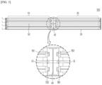
- FIG. 3 is a plan view of a battery module of the present invention and an enlarged view of its main part
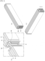
- FIG. 4 is a perspective view showing a configuration of an electrode assembly of the battery module of the present invention
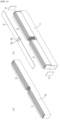
- FIG. 5 is an exploded perspective view illustrating an assembly process of the battery module of FIG. 4 .
- the battery module of the present invention includes: a first battery cell assembly 10 in which battery cells 1 are stacked in the thickness direction of the battery cell; a second battery cell assembly 20 in which each battery cell 1 stacked in the first battery cell assembly 10 and each battery cell 1 arranged in a row in the longitudinal direction of the battery cell is stacked in the thickness direction of the battery cell in the same number as the number of battery cells stacked in the first battery cell assembly 10.
- four first and second battery cell assemblies 10, 20 are stacked in the battery cell thickness direction, respectively.
- the battery cells of the same layer of the first and second battery cell assemblies 10, 20 are disposed to face each other in the longitudinal direction.
- the module case 30 accommodating the battery cell assemblies also has a rectangular parallelepiped shape elongated along the longitudinal direction.
- the battery cells of the first and second battery cell assemblies are respectively connected to the terminal busbars TB1, TB2 located between the first and second battery cell assemblies 10, 20, but it can be seen that the first and second battery cell assemblies 10, 20 are not electrically connected to each other.
- the terminal busbars are represented as TB 1 and TB2 according to their polarities.
- the battery cells constituting the first and second battery cell assemblies 10, 20 may employ pouch cells in which electrode leads having different polarities are protruded from both ends of the battery cells, so-called bidirectional pouch cells.
- the number of battery cells 1 stacked in the battery cell thickness direction is an even number.
- a first partition 40 extending in the battery cell thickness direction may be provided between the first and second battery cell assemblies 10, 20. Heat propagation between the first and second battery cell assemblies 10, 20 can be prevented by the first partition 40.
- the first partition 40 is not shown for the convenience of illustration.
- the number of battery cells 1 stacked in the battery cell thickness direction is an even number, they can be divided into the same number up and down. That is, a second partition 50 extending in the longitudinal direction of the module case 30 is installed in the middle part (in the example of FIG. 3 , it is installed between two upper and lower battery cells) of the battery cells stacked in the thickness direction of the first and second battery cell assemblies 10, 20.
- the second partition 50 can prevent heat from propagating in the thickness direction.
- terminal busbars TB1, TB2 are provided between the first and second battery cell assemblies 10, 20. Specifically, in the case of electrically connecting the stacked battery cells, the terminal busbars TB1, TB2 are coupled to the end of the electrical path. As described below, the terminal busbars TB1, TB2 are electrically connected to terminal busbars TB1, TB2 of adjacent battery modules by being coupled to high voltage busbars.
- FIG. 4 are perspective views of the first or second battery cell assembly constituting the battery module 100 of the present invention viewed from the front side and the rear side, respectively, and (a) of FIG. 4 is a perspective view showing the side where the first and second battery cell assemblies are disposed to face each other.
- inter busbar IB the leads of the battery cell 1 to which the terminal busbars TB1, TB2 are not coupled are electrically connected to each other by an inter busbar IB.
- the inter busbar IB is coupled to the support plate between the terminal busbars TB1, TB2 (refer to FIG. 4 (a) ), and the leads of the battery cells located at the longitudinal ends of the first and second battery cell assemblies 10, 20 are connected to each other by the inter busbar IB (refer to (b) and (c) of FIG. 4 ).
- FIG. 5 shows that the first and second battery cell assemblies 10, 20 are accommodated in the module case 30.
- the module case 30 includes a U-shaped frame 31 having an open top and an upper frame 32 coupled thereto, but is not limited thereto. That is, a C-shaped frame having one side opened and an I-shaped frame coupled thereto may also be used, and other types of module cases 30 may be used as long as they can stably accommodate the battery cell assemblies.
- the module case 30 includes a front end plate 33 and a rear end plate 34 coupled to the front and rear ends of the battery cell assembly.
- a concave part is formed in the center of the upper frame 32, and a through hole 32a is formed in the concave part so that the terminal part of the terminal busbar coupled to the battery cell assembly can protrude.
- the terminal part of the terminal busbar protruding through the through hole 32a is coupled to a high voltage busbar to be described below.
- FIG. 6 is a schematic diagram showing an electrical path in the case of stacking the battery modules of the present invention compared to the electrical path of FIG. 2 .
- a battery module stack may be formed by stacking a plurality of battery modules in the battery cell thickness direction. A detailed configuration of the battery module stack will be described below in relation to the battery pack.
- FIG. 6 is a description of an electrical path of an electrical connection structure of a battery module stack structure consisting of the first and second battery cell assemblies of FIG. 2
- FIG. 6 a description of an electrical path of an electrical connection structure of a battery module stack structure consisting of the first and second battery cell assemblies of the present invention.
- the battery cell assembly of FIG. 6 is electrically connected to the electrode leads R of each adjacent battery cell so as to form an electrical path in which four battery cells 1, 1' stacked in the thickness direction are connected in a zigzag direction.
- the electrode leads R of the battery cells 1, 1' adjacent to each other are bent and directly coupled to each other by, for example, welding, or, as shown in FIG. 4 , they may be electrically connected through the inter busbar IB.
- Both ends of the electrical path connected in the zigzag direction become the electrode lead part protruding toward the gap between the first and second battery cell assemblies, respectively, among the electrode leads at both ends of the battery cells included in the first and second battery cell assemblies 10', 20710,201.
- the electrode lead parts respectively protruding from the first and second battery cell assemblies 10', 20'/10, 20 have opposite polarities.
- the above-described terminal busbar is coupled to the electrode lead part of both ends of the electrical path.
- the (a) of FIG. 4 and (b) of FIG. 4 are different in that in the example of (a) of FIG. 4 , one among the electrode lead parts respectively protruding toward the gap between the first and second battery cell assemblies connects between the first and second battery cell assemblies 10', 20', whereas in the example of (b) of FIG. 4 , it does not connect between the first and second battery cell assemblies 10, 20.
- a first partition 40 extending in the battery cell thickness direction is formed between the first and second battery cell assemblies, so it seems that the electrode lead parts are disconnected in the example of (a) of FIG. 6 , but in reality, they are connected to each other through the first partition 40.
- a battery pack as another aspect of the present invention includes a battery module stack 1000 formed by stacking the above-described a plurality of battery modules 100 in the thickness direction of the battery cell.
- the first battery cell assemblies 10 are electrically connected to each other to form a first electric block P
- the second battery cell assemblies 20 are electrically connected to each other to form a second electric block Q.
- each of the first battery cell assembly 10 and the second battery cell assembly 20 constituting the first electric block P and the second electric block Q are not electrically connected to each other.
- the battery pack 2000 of the present invention includes a battery module stack 1000 formed by stacking a plurality of above-described battery modules 100 in which the first and second battery cell assemblies are not electrically connected to each other in the thickness direction of the battery cell.
- the first battery cell assemblies 10 of the battery modules 10 stacked in the thickness direction are electrically connected to each other to form a first electric block P.
- the second battery cell assemblies 20 of the battery modules stacked in the thickness direction are electrically connected to each other to form a second electric block Q.
- the battery module stack 1000 provided in the battery pack of the present invention has the first and second electric blocks P, Q that are not electrically connected to each other in principle. That is, since the first and second battery cell assemblies 10, 20 of each battery module constituting the first and second electric blocks P, Q are not electrically connected, the first and second electric blocks P, Q are not electrically connected to each other. However, since the first and second battery cell assemblies of the battery modules stacked on the top of the battery module stack are electrically connected by, for example, a high voltage busbar HB3, the first electric block P and the second electric block Q are electrically connected to each other at the top of the battery module stack 1000. Therefore, referring to FIG.
- the first and second electric blocks P, Q of eight battery modules from the bottom are not electrically connected to each other, but in the ninth battery module, the first and second electrical blocks P, Q are electrically connected.
- FIG. 6 and FIG. 7 show an example of the battery module stack.
- (a) of FIG. 6 is the same as that shown in FIG. 2 , and shows that an internal short circuit is formed by thermal runaway. That is, since the battery module stack of (a) of FIG. 6 is a stack of battery modules 100' in which the first and second battery cell assemblies 10', 20' are electrically connected to each other, when the first battery cell assemblies and second battery cell assemblies of the adjacent battery modules are connected to each other with a high voltage busbar to form electrical blocks P, Q, respectively, the electrical blocks P, Q also become electrically connected. In the case of (a) of FIG.
- thermal runaway TR when thermal runaway TR occurs in one battery cell 1' of the battery cell assembly and propagates to the battery cell 1' of the adjacent battery module, causing the electrical circuit to consequently become connected, an internal short circuit is formed.
- the thermal runaway TR is not sequentially propagated, but it may be propagated in a thermal runaway TR propagation sequence jumping from the first battery cell assembly 10' to the second battery cell assembly 20' depending on the internal short circuit. That is, as shown in (b) of FIG. 1 , when electricity flows along an inverted U-shaped path, thermal runaway does not sequentially spread up and down from the part where thermal runaway has occurred, but spreads left and right, etc. due to an internal short circuit and increases in propagation speed. In this case, the amount of gas generated in the battery pack greatly increases, and the risk of explosion also rapidly increases.
- thermal runaway occurs in the first battery cell assembly 10 on the left side
- thermal runaway is only propagated to the upper and lower battery modules 100 and does not propagate toward the second battery cell assembly 20 on the right side, specifically the second electric block (Q).
- the second electric block (Q) is because, in principle, there is no electrical connection between the first and second battery cell assemblies 10, 20 and the first and second electric blocks P, Q, thereby does not form an internal short circuit.
- FIG. 7 is a plan view showing an electrical connection structure of a battery module stack in which battery modules according to the present invention are stacked.
- FIG. 7 also shows the effect of the battery pack including the battery module stack 1000 of the present invention.
- the first and second electrical blocks P, Q are not electrically connected to each other. Therefore, it is a structure in which the left and right electric block parts P, Q are respectively separately propagated during thermal runaway.
- the flow of electricity must be in an inverted U-shape as shown in FIG. 7 , so the first and second battery cell assemblies 10, 20 of the battery modules 100 stacked on the top of the battery module stack 1000 need to be electrically connected.
- thermal runaway TR does not propagate among the first and second battery cell assemblies 10, 20 of each battery module 100 until it reaches the top, but instead it propagates sequentially. Additionally, the present invention suppresses the occurrence of an internal short circuit in the battery pack, preventing thermal runaway TR from rapidly propagating and allowing it to propagate sequentially, thereby reducing the amount of gas generation and greatly reducing the risk of explosion.
- the electrical connection structure of the battery pack is greatly simplified.
- the first and second high voltage busbars HB1, HB2 are coupled to the terminal busbars TB1, TB2 of different polarities exposed to the top of the battery module, respectively, so that they can electrically connect the battery modules 100 to each other.
- the electrical connection between the first and second battery cell assemblies 10, 20 of the battery modules 100 stacked on the top of the battery module stack 1000 may be performed by a high voltage busbar HB3.
- a high voltage busbar HB3 third high voltage busbar
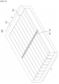
- FIG. 8 is a perspective view of a battery pack 2000 including a battery module stack 1000 composed of battery modules according to the present invention.
- the battery module stack 1000 is the same as that shown in FIG. 7 , and two high voltage busbars (HB 1, HB2) are coupled side by side to the center of the first and second electric blocks P, Q in the module stacking direction.
- HB 1, HB2 high voltage busbars
- the electrical connection structure is simplified, the utilization of space inside the pack is increased, and a battery pack 2000 capable of preventing the occurrence of an internal short circuit can be obtained.
- FIG. 9 is examples showing other stacking structures and electrical connection structures of the battery module stack 1000 composed of the battery modules and the battery modules of the present invention.
- the electrical connection structure of the first and second battery cell assemblies 10, 20 was a 1P4S structure, respectively.
- the electrical connection structure of the battery module may be other structures such as 1P2S and 1P6S.
- a 1P8S electrical connection structure may also be employed.
- the electrical connection structure of the first and second battery cell assemblies 10 and 20 may be 1PNS (N is an even number).
- the first and second battery cell assemblies 10, 20 between the stacked battery modules 100, the first electric block P formed by connecting the adjacent first battery cell assemblies 10 to each other, and the second electric block Q formed by connecting the second battery cell assemblies 20 to each other are not electrically connected to each other, except for the first and second battery cell assemblies 10, 20 of the battery modules 100 at the end.
Landscapes
- Chemical & Material Sciences (AREA)
- Chemical Kinetics & Catalysis (AREA)
- Electrochemistry (AREA)
- General Chemical & Material Sciences (AREA)
- Connection Of Batteries Or Terminals (AREA)
- Battery Mounting, Suspending (AREA)
Abstract
Description
- The present invention relates to a battery module and a battery pack including the same.
- More specifically, it relates to a battery module and a battery pack that can prevent an internal short circuit from being electrically formed due to a simple electrical connection structure.
- This application claims the benefit of priority based on
Korean Patent Application No. 10-2021-0144831 filed on October 27, 2021 - Recently, secondary batteries capable of charging and discharging have been widely used as energy sources of wireless mobile devices. In addition, the secondary battery has attracted attention as an energy source of electric vehicles, hybrid electric vehicles, and the like, which are proposed as a solution for air pollution and the like of existing gasoline vehicles and diesel vehicles using fossil fuels. Accordingly, the types of applications using the secondary battery have diversified due to the advantages of the secondary battery, and it is expected that the secondary battery will be applied to many fields and products in the future.
- In addition, as an Energy Storage System (ESS) and a power source for an electric vehicle, or the like, there is an increasing demand for a battery module accommodating a plurality of secondary batteries electrically connected in series or in parallel and a battery pack composed of the battery modules.
- Such a battery module or battery pack includes an external housing made of a metal material to protect a plurality of secondary batteries from external impacts or receive and store the secondary batteries.
-
FIG. 1 is a plan view (FIG. 1(a) ) showing an example of a structure of a battery module 100' having expandability proposed by the present applicant, and a plan view (FIG. 1(b) ) of a battery module stack 1000' configured by stacking the battery modules 100', andFIG. 2 is a schematic diagram showing an electrical path of the battery module stack 1000' composed of the battery modules ofFIG. 1 . - The present applicant has invented a battery module 100' accommodating an electrode assembly composed of a first battery cell assembly 10' in which a plurality of battery cells 1' are stacked in the battery cell thickness direction, and a second battery cell assembly 20' facing the first battery cell assembly 10' in the battery cell longitudinal direction and comprising a plurality of battery cells in the battery cell thickness direction in the same way as the first battery cell assembly 10', in a rectangular parallelepiped shape module case 30' elongated in the longitudinal direction. Such a battery module 100' accommodates a relatively small number of battery cells in each module case 30', and stacks the battery modules in the longitudinal direction or the thickness direction of the battery cell like Lego blocks, so that a battery pack may be freely configured in consideration of the space where the battery module 100' is installed or the installation space of the battery pack. As such, since the battery module 100' proposed by the present applicant can manufacture various types of battery packs based on the stacking (designing) method, it can be referred to as an expandable battery module.
- However, the expandable battery modules proposed so far had a structure in which the first and second battery cell assemblies 10', 20' facing each other in the longitudinal direction are electrically connected to each other. Referring to
FIG. 1 , the battery cells in the lower two rows of the first and second battery cell assemblies 10', 20' are not connected to each other, but the battery cells in the upper two rows of the first and second battery cell assemblies 10', 20' are electrically connected to each other (refer to the electricity connecting part of A inFIG. 1 ). - However, the expandable battery module with this electrical connection structure has the following problems.
- Since the first and second battery cell assemblies 10', 20' are electrically connected, the electrical connection structure of the battery module itself becomes complicated, and as a result, in the case of stacking a battery module including the first and second battery cell assemblies 10', 20', a total of three lines (a, b, c) of high voltage busbars are required as shown in
FIG. 1(b) to electrically connect between the battery cell assemblies of each battery module. - In particular, referring to
FIG. 2 , when thermal runaway (hereinafter referred to as `TR' for short) occurs in some of the battery cells of the stacked battery module 100', there has been a problem in that an internal short circuit is formed. That is, inFIG. 2(a) , adjacent battery modules are only electrically connected to each other by the above-described high voltage busbars, and the battery cells between each module should not be directly connected to each other. However, when thermal runaway occurs in one battery cell 1', the battery cell 1' is melted and comes into contact with the module case 30', and thermal runaway is propagated to the module case 30' of the adjacent module and the battery cell' located inside the module case. Accordingly, as show inFIG. 2(b) , thermal runaway proceeds along the stacking direction of the battery modules, so that thermal runaway propagates between the first battery cell assemblies 10' of the left battery modules. However, since the first battery cell assembly 10' of the battery modules is electrically connected to the second battery cell assembly 20' of each battery module, respectively, even the second battery cell assembly 20' becomes shortcircuited, thereby an electrical internal short circuit is formed in the entire battery module 100' or the battery module stack 1000' (seeFIG. 2(c) ). As such, if a short circuit is formed inside a battery module or a battery pack, gas is rapidly generated and overheated, thereby danger of explosion of a battery pack increases. - Therefore, in terms of a battery module having expandability and a battery pack constituted by the same, a development of technology capable of preventing or delaying the generation of an internal short circuit during thermal runaway while maximizing the use of internal space by simplifying the electrical connection structure is required.
- (Patent Document 1)
Korean Patent Publication No. 10-2020-0131500 - The present invention was made to solve the above problems, and it is directed to provide a battery module and a battery pack that can simplify the electrical connection structure by excluding the electrical connection between two battery cell assemblies constituting the expandable module and can prevent the occurrence of an internal short circuit.
- The battery module according to the present invention for solving the above problems includes: a first battery cell assembly in which a plurality of battery cells are stacked in the thickness direction of the battery cell; a second battery cell assembly in which each battery cell arranged in a row in the longitudinal direction of the battery cell with respect to each battery cell stacked in the first battery cell assembly is stacked in the thickness direction of the battery cell in the same number as the number of battery cells stacked in the first battery cell assembly; and a module case accommodating the first and second battery cell assembly, wherein the battery cells of the first battery cell assembly are electrically connected to each other, and the battery cells of the second battery cell assembly are electrically connected to each other, but the battery cells are not electrically connected to each other between the first and second battery cell assemblies.
- As an example, the battery cells constituting the first battery cell assembly and the second battery cell assembly may be pouch cells from which electrode leads of different polarities are protruded from both ends.
- As an example, the number of stacked battery cells of the first battery cell assembly and the second battery cell assembly is an even number.
- Specifically, the battery cells included in the first battery cell assembly and the second battery cell assembly are electrically connected to the electrode leads of adjacent battery cells so as to form an electrical path connected in a zigzag direction, respectively, and both ends of the electrical path may be electrode leads that are protruding toward the gap between the first and second battery cell assemblies among the electrode leads at both ends of the battery cells included in the first and second battery cell assemblies.
- In addition, the electrode leads of the battery cells included in the first and second battery cell assemblies, which are each protruding toward the gap between the first and second battery cell assemblies, have opposite polarities.
- Additionally, a terminal busbar may be coupled to the electrode leads respectively protruding from the first and second battery cell assemblies toward the gap between the first and second battery cell assemblies.
- As an example, electrode leads of adjacent battery cells are coupled through an inter busbar or directly coupled by being bent to each other so as to form an electrical path connected in the zigzag direction.
- As another example, a first partition extending in the battery cell thickness direction may be installed between the first battery cell assembly and the second battery cell assembly.
- In addition, a second partition extending in the longitudinal direction of the module case may be provided in the middle part of the battery cells stacked in the thickness direction of the first battery cell assembly and the second battery cell assembly.
- As another aspect of the present invention, the battery pack includes a battery module stack in which a plurality of the battery modules are stacked in the thickness direction of the battery cells. The first battery cell assemblies of battery modules stacked in the thickness direction are electrically connected to each other to constitute a first electric block, and the second battery cell assemblies are electrically connected to each other to constitute a second electric block. Except for the first and second battery cell assemblies of battery modules stacked at the top of the battery module stack, each of the first and second battery cell assemblies constituting the first electric block and the second electric block is not electrically connected to each other.
- The first and second battery cell assemblies of battery modules stacked at the top of the battery module stack are electrically connected by a high voltage busbar to electrically connect the first electric block and the second electric block.
- As an example, a first high voltage busbar electrically connecting the first battery cell assemblies to each other and a second high voltage busbar electrically connecting the second battery cell assemblies to each other may be installed on the battery module in the stacking direction of the battery module in order to constitute the first electric block and the second electric block.
- Specifically, the first high voltage busbar is connected to a terminal busbar coupled to an electrode lead of a battery cell protruding from the first battery cell assembly toward the gap between the first battery cell assembly and the second battery cell assembly of the battery module, and the second high voltage busbar is connected to a terminal busbar coupled to an electrode lead of a battery cell protruding from the second battery cell assembly toward the gap between the first battery cell assembly and the second battery cell assembly of the battery module.
- As an example, the electrical connection structure of the first and second battery cell assemblies is a 1PNS structure, and N is an even number.
- According to the present invention, the electrical connection structure of an expandable battery module including two battery cell assemblies and a battery pack formed by stacking the battery modules can be greatly simplified.
- In addition, since each battery cell assembly independently constitutes an electric circuit, the formation of an internal short circuit can be delayed as much as possible or controlled to be formed in order. Accordingly, the safety of the battery pack can be further improved.
-
-
FIG. 1 is a plan view showing an example of a structure of a battery module having expandability proposed by the present applicant, and a plan view of a battery module stack configured by stacking the battery modules. -
FIG. 2 is a schematic diagram showing an electrical path of a battery module stack composed of the battery modules ofFIG. 1 . -
FIG. 3 is a plan view of a battery module of the present invention and an enlarged view of its main part. -
FIG. 4 is a perspective view showing a configuration of an electrode assembly of the battery module of the present invention. -
FIG. 5 is an exploded perspective view illustrating an assembly process of the battery module ofFIG. 4 . -
FIG. 6 is a schematic diagram showing an electrical path in the case of stacking the battery modules of the present invention in comparison with the electrical path ofFIG. 2 . -
FIG. 7 is a plan view of an electrical connection structure of a battery module stack in which the battery modules of the present invention are stacked. -
FIG. 8 is a perspective view of a battery pack including a battery module stack composed of the battery module of the present invention. -
FIG. 9 is examples showing other stacking structures of the battery module stack composed of the battery module and the battery module of the present invention. -
- 1: BATTERY CELL
- 10: FIRST BATTERY CELL ASSEMBLY
- 20: SECOND BATTERY CELL ASSEMBLY
- 30: MODULE CASE
- 40: FIRST PARTITION
- 50: SECOND PARTITION
- TB1, TB2: TERMINAL BUSBAR
- IB: INTER BUSBAR
- TR: THERMAL RUNAWAY
- HB1, HB2, HB3: FIRST HIGH VOLTAGE BUSBAR, SECOND HIGH VOLTAGE BUSBAR, THIRD HIGH VOLTAGE BUSBAR
- R: ELECTRODE LEAD
- P: FIRST ELECTRIC BLOCK
- Q: SECOND ELECTRIC BLOCK
- 100: BATTERY MODULE
- 1000: BATTERY MODULE STACK
- 2100: BATTERY PACK CASE
- 2000: BATTERY PACK
- Hereinafter, the present invention will be described in detail. Prior to this, the terms or words used in the present specification and claims should not be interpreted as being limited to conventional or dictionary meanings and should be interpreted with meanings and concepts which are consistent with the technological scope of the invention based on the principle that the inventors have appropriately defined concepts of the terms in order to describe the invention in the best way.
- In this application, it should be understood that terms such as "comprise" or "have" are intended to designate that there is a feature, a number, a step, an operation, a component, a part, or a combination thereof described in the specification, and they do not exclude in advance the possibility of the presence or addition of one or more other features or numbers, steps, operations, components, parts or combinations thereof.
- In addition, when a portion, such as a layer, a film, an area, a plate, etc., is referred to as being "on" another portion, this includes not only the case where the portion is "directly on" another portion but also the case where still another portion is interposed therebetween. On the other hand, when a portion, such as a layer, a film, an area, a plate, etc., is referred to as being "under" another portion, this includes not only the case where the portion is "directly under" another portion but also the case where still another portion is interposed therebetween. In addition, to be disposed "on" in the present application may include being disposed at the bottom as well as the top.
- The battery module according to the present invention includes: a first battery cell assembly in which a plurality of battery cells are stacked in the thickness direction of the battery cell; a second battery cell assembly in which each battery cell arranged in a row in the longitudinal direction of the battery cell with respect to each battery cell stacked in the first battery cell assembly is stacked in the thickness direction of the battery cell in the same number as the number of battery cells stacked in the first battery cell assembly; and a module case accommodating the first and second battery cell assembly, wherein the battery cells of the first battery cell assembly are electrically connected to each other, and the battery cells of the second battery cell assembly are electrically connected to each other, but the battery cells are not electrically connected to each other between the first and second battery cell assemblies.
-
FIG. 3 is a plan view of a battery module of the present invention and an enlarged view of its main part,FIG. 4 is a perspective view showing a configuration of an electrode assembly of the battery module of the present invention, andFIG. 5 is an exploded perspective view illustrating an assembly process of the battery module ofFIG. 4 . - As illustrated in
FIG. 3 , the battery module of the present invention includes: a firstbattery cell assembly 10 in whichbattery cells 1 are stacked in the thickness direction of the battery cell; a secondbattery cell assembly 20 in which eachbattery cell 1 stacked in the firstbattery cell assembly 10 and eachbattery cell 1 arranged in a row in the longitudinal direction of the battery cell is stacked in the thickness direction of the battery cell in the same number as the number of battery cells stacked in the firstbattery cell assembly 10. In the present exemplary embodiment, four first and secondbattery cell assemblies battery cell assemblies module case 30 accommodating the battery cell assemblies also has a rectangular parallelepiped shape elongated along the longitudinal direction. As shown in the enlarged view ofFIG. 3 , the battery cells of the first and second battery cell assemblies are respectively connected to the terminal busbars TB1, TB2 located between the first and secondbattery cell assemblies battery cell assemblies TB 1 and TB2 according to their polarities. - The battery cells constituting the first and second
battery cell assemblies battery cells 1 stacked in the battery cell thickness direction is an even number. - A
first partition 40 extending in the battery cell thickness direction may be provided between the first and secondbattery cell assemblies battery cell assemblies first partition 40. However, inFIG. 4 andFIG. 5 , thefirst partition 40 is not shown for the convenience of illustration. In addition, since the number ofbattery cells 1 stacked in the battery cell thickness direction is an even number, they can be divided into the same number up and down. That is, asecond partition 50 extending in the longitudinal direction of themodule case 30 is installed in the middle part (in the example ofFIG. 3 , it is installed between two upper and lower battery cells) of the battery cells stacked in the thickness direction of the first and secondbattery cell assemblies second partition 50 can prevent heat from propagating in the thickness direction. - In the
battery module 100 of the present invention, terminal busbars TB1, TB2 are provided between the first and secondbattery cell assemblies
(b) and (c) ofFIG. 4 are perspective views of the first or second battery cell assembly constituting thebattery module 100 of the present invention viewed from the front side and the rear side, respectively, and (a) ofFIG. 4 is a perspective view showing the side where the first and second battery cell assemblies are disposed to face each other. Referring toFIG. 4 , it can be seen that the leads of thebattery cell 1 to which the terminal busbars TB1, TB2 are not coupled are electrically connected to each other by an inter busbar IB. InFIG. 4 , the inter busbar IB is coupled to the support plate between the terminal busbars TB1, TB2 (refer toFIG. 4 (a) ), and the leads of the battery cells located at the longitudinal ends of the first and secondbattery cell assemblies FIG. 4 ). -
FIG. 5 shows that the first and secondbattery cell assemblies module case 30. Themodule case 30 includes a U-shaped frame 31 having an open top and anupper frame 32 coupled thereto, but is not limited thereto. That is, a C-shaped frame having one side opened and an I-shaped frame coupled thereto may also be used, and other types ofmodule cases 30 may be used as long as they can stably accommodate the battery cell assemblies. Themodule case 30 includes afront end plate 33 and a rear end plate 34 coupled to the front and rear ends of the battery cell assembly. A concave part is formed in the center of theupper frame 32, and a throughhole 32a is formed in the concave part so that the terminal part of the terminal busbar coupled to the battery cell assembly can protrude. The terminal part of the terminal busbar protruding through the throughhole 32a is coupled to a high voltage busbar to be described below. -
FIG. 6 is a schematic diagram showing an electrical path in the case of stacking the battery modules of the present invention compared to the electrical path ofFIG. 2 . - As shown in
FIG. 6 , a battery module stack may be formed by stacking a plurality of battery modules in the battery cell thickness direction. A detailed configuration of the battery module stack will be described below in relation to the battery pack. - The electrical connection structures of the battery cell assembly and the battery module stack provided in the battery pack of the present invention will be described by referring to
FIG. 3 ,FIG. 4 , andFIG. 6 .
(a) ofFIG. 6 is a description of an electrical path of an electrical connection structure of a battery module stack structure consisting of the first and second battery cell assemblies ofFIG. 2 , and(b) ofFIG. 6 a description of an electrical path of an electrical connection structure of a battery module stack structure consisting of the first and second battery cell assemblies of the present invention. - The battery cell assembly of
FIG. 6 is electrically connected to the electrode leads R of each adjacent battery cell so as to form an electrical path in which fourbattery cells 1, 1' stacked in the thickness direction are connected in a zigzag direction. In order to form the electrical path connected in the zigzag direction, the electrode leads R of thebattery cells 1, 1' adjacent to each other are bent and directly coupled to each other by, for example, welding, or, as shown inFIG. 4 , they may be electrically connected through the inter busbar IB. - Both ends of the electrical path connected in the zigzag direction become the electrode lead part protruding toward the gap between the first and second battery cell assemblies, respectively, among the electrode leads at both ends of the battery cells included in the first and second
battery cell assemblies 10', 20710,201. In this case, the electrode lead parts respectively protruding from the first and second battery cell assemblies 10', 20'/10, 20 have opposite polarities. The above-described terminal busbar is coupled to the electrode lead part of both ends of the electrical path. - The (a) of
FIG. 4 and (b) ofFIG. 4 are different in that in the example of (a) ofFIG. 4 , one among the electrode lead parts respectively protruding toward the gap between the first and second battery cell assemblies connects between the first and second battery cell assemblies 10', 20', whereas in the example of (b) ofFIG. 4 , it does not connect between the first and secondbattery cell assemblies FIG. 6 , afirst partition 40 extending in the battery cell thickness direction is formed between the first and second battery cell assemblies, so it seems that the electrode lead parts are disconnected in the example of (a) ofFIG. 6 , but in reality, they are connected to each other through thefirst partition 40. When a battery pack is formed by stacking battery modules having such electrical connection structure, the structure becomes complicated such as additionally connecting three high voltage busbars as shown inFIG. 1 , but there is a problem in that an internal short circuit is formed. This will be described in more detail in relation to the battery pack of the present invention below. - A battery pack as another aspect of the present invention includes a
battery module stack 1000 formed by stacking the above-described a plurality ofbattery modules 100 in the thickness direction of the battery cell. The firstbattery cell assemblies 10 are electrically connected to each other to form a first electric block P, and the secondbattery cell assemblies 20 are electrically connected to each other to form a second electric block Q. Except for the first and secondbattery cell assemblies battery module stack 1000, each of the firstbattery cell assembly 10 and the secondbattery cell assembly 20 constituting the first electric block P and the second electric block Q are not electrically connected to each other. - The
battery pack 2000 of the present invention includes abattery module stack 1000 formed by stacking a plurality of above-describedbattery modules 100 in which the first and second battery cell assemblies are not electrically connected to each other in the thickness direction of the battery cell. In thebattery module stack 1000, the firstbattery cell assemblies 10 of thebattery modules 10 stacked in the thickness direction are electrically connected to each other to form a first electric block P. In addition, in thebattery module stack 1000, the secondbattery cell assemblies 20 of the battery modules stacked in the thickness direction are electrically connected to each other to form a second electric block Q. In the same way that the first and secondbattery cell assemblies battery module stack 1000 provided in the battery pack of the present invention has the first and second electric blocks P, Q that are not electrically connected to each other in principle. That is, since the first and secondbattery cell assemblies battery module stack 1000. Therefore, referring toFIG. 7 , among the nine battery modules constituting the first electric block and the second electric block, the first and second electric blocks P, Q of eight battery modules from the bottom are not electrically connected to each other, but in the ninth battery module, the first and second electrical blocks P, Q are electrically connected. -
FIG. 6 andFIG. 7 show an example of the battery module stack.
(a) ofFIG. 6 is the same as that shown inFIG. 2 , and shows that an internal short circuit is formed by thermal runaway. That is, since the battery module stack of (a) ofFIG. 6 is a stack of battery modules 100' in which the first and second battery cell assemblies 10', 20' are electrically connected to each other, when the first battery cell assemblies and second battery cell assemblies of the adjacent battery modules are connected to each other with a high voltage busbar to form electrical blocks P, Q, respectively, the electrical blocks P, Q also become electrically connected. In the case of (a) ofFIG. 6 , when thermal runaway TR occurs in one battery cell 1' of the battery cell assembly and propagates to the battery cell 1' of the adjacent battery module, causing the electrical circuit to consequently become connected, an internal short circuit is formed. In this case, the thermal runaway TR is not sequentially propagated, but it may be propagated in a thermal runaway TR propagation sequence jumping from the first battery cell assembly 10' to the second battery cell assembly 20' depending on the internal short circuit. That is, as shown in (b) ofFIG. 1 , when electricity flows along an inverted U-shaped path, thermal runaway does not sequentially spread up and down from the part where thermal runaway has occurred, but spreads left and right, etc. due to an internal short circuit and increases in propagation speed. In this case, the amount of gas generated in the battery pack greatly increases, and the risk of explosion also rapidly increases. - On the other hand, in the case of (b) of
FIG. 6 , that is, the present invention, even if thermal runaway occurs in the firstbattery cell assembly 10 on the left side, thermal runaway is only propagated to the upper andlower battery modules 100 and does not propagate toward the secondbattery cell assembly 20 on the right side, specifically the second electric block (Q). This is because, in principle, there is no electrical connection between the first and secondbattery cell assemblies -
FIG. 7 is a plan view showing an electrical connection structure of a battery module stack in which battery modules according to the present invention are stacked. -
FIG. 7 also shows the effect of the battery pack including thebattery module stack 1000 of the present invention. As described above, in thebattery module stack 1000 of the present invention, except for thebattery module 100 stacked on the top of the stack, the first and second electrical blocks P, Q are not electrically connected to each other. Therefore, it is a structure in which the left and right electric block parts P, Q are respectively separately propagated during thermal runaway. However, due to the structure of the battery pack which has to be connected to, for example, electric components of a vehicle, the flow of electricity must be in an inverted U-shape as shown inFIG. 7 , so the first and secondbattery cell assemblies battery modules 100 stacked on the top of thebattery module stack 1000 need to be electrically connected. However, even in this case, thermal runaway TR does not propagate among the first and secondbattery cell assemblies battery module 100 until it reaches the top, but instead it propagates sequentially. Additionally, the present invention suppresses the occurrence of an internal short circuit in the battery pack, preventing thermal runaway TR from rapidly propagating and allowing it to propagate sequentially, thereby reducing the amount of gas generation and greatly reducing the risk of explosion. - In addition, as shown in
FIG. 7 , if it is a structure in which the first and second electric blocks P, Q are not electrically connected to each other, when connecting the high voltage busbars (that is, the first high voltage busbar HB land the second high voltage busbar HB2) to the terminal busbars TB1, TB2 provided in the first and secondbattery cell assemblies battery module 100, it is sufficient to be provided with only two high voltage busbars (HB1, HB2) extending in the stacking direction of the battery module. That is, there is no need to prepare three high voltage busbars as shown inFIG. 1 . Accordingly, the electrical connection structure of the battery pack is greatly simplified. As shown in the enlarged view ofFIG. 7 , the first and second high voltage busbars HB1, HB2 are coupled to the terminal busbars TB1, TB2 of different polarities exposed to the top of the battery module, respectively, so that they can electrically connect thebattery modules 100 to each other. - Meanwhile, the electrical connection between the first and second
battery cell assemblies battery modules 100 stacked on the top of thebattery module stack 1000 may be performed by a high voltage busbar HB3. Specifically, by connecting the teminal busbars TB1, TB2 coupled to the electrode leads of the battery cells protruding toward the gap between the first and secondbattery cell assemblies battery modules 100 stacked on the top to the high voltage busbar HB3 (third high voltage busbar), it may be possible to implement an inverted U-shaped electrical path in the battery module stack. -
FIG. 8 is a perspective view of abattery pack 2000 including abattery module stack 1000 composed of battery modules according to the present invention. - The
battery module stack 1000 is the same as that shown inFIG. 7 , and two high voltage busbars (HB 1, HB2) are coupled side by side to the center of the first and second electric blocks P, Q in the module stacking direction. When thebattery module stack 1000 is accommodated in an appropriatebattery pack case 2100, the electrical connection structure is simplified, the utilization of space inside the pack is increased, and abattery pack 2000 capable of preventing the occurrence of an internal short circuit can be obtained. -
FIG. 9 is examples showing other stacking structures and electrical connection structures of thebattery module stack 1000 composed of the battery modules and the battery modules of the present invention. - (a) of
FIG. 9 shows a structure of stacking one, two, and four battery modules in which the first and secondbattery cell assemblies - (b) of
FIG. 9 shows a structure of stacking one, two, and four battery modules in which the first and secondbattery cell assemblies - In
FIG. 3 to FIG. 6 , the electrical connection structure of the first and secondbattery cell assemblies FIG. 9 , the electrical connection structure of the battery module may be other structures such as 1P2S and 1P6S. For example, although not shown inFIG. 9 , a 1P8S electrical connection structure may also be employed. In short, the electrical connection structure of the first and secondbattery cell assemblies battery cell assemblies stacked battery modules 100, the first electric block P formed by connecting the adjacent firstbattery cell assemblies 10 to each other, and the second electric block Q formed by connecting the secondbattery cell assemblies 20 to each other are not electrically connected to each other, except for the first and secondbattery cell assemblies battery modules 100 at the end. - As above, the diagrams disclosed in the present invention are not intended to limit but to explain the technological idea of the present invention, and the scope of the technological idea of the present invention is no limited by these diagrams. The technological scope of the present invention should be construed according to the following claims, and all technological ideas within the equivalent scope should be construed as being included in the scope of rights of the present invention.
- Meanwhile, terms indicating directions such as up, down, left, right, front, and back are used in this specification, but these terms are only for convenience of description and may vary depending on the position of the target object or the position of the observer.
Claims (15)
- A battery module, comprising:a first battery cell assembly in which a plurality of battery cells are stacked in the thickness direction of the battery cell;a second battery cell assembly in which each battery cell arranged in a row in the longitudinal direction of the battery cell with respect to each battery cell stacked in the first battery cell assembly is stacked in the thickness direction of the battery cell in the same number as the number of battery cells stacked in the first battery cell assembly; anda module case accommodating the first and second battery cell assembly,wherein,the battery cells of the first battery cell assembly are electrically connected to each other, andthe battery cells of the second battery cell assembly are electrically connected to each other, andthe battery cells are not electrically connected to each other between the first and second battery cell assemblies.
- The battery module of claim 1, wherein
the battery cells constituting the first battery cell assembly and the second battery cell assembly are pouch cells from which electrode leads of different polarities are protruded from both ends. - The battery module of claim 2, wherein
the number of stacked battery cells of the first battery cell assembly and the second battery cell assembly is an even number. - The battery module of claim 3, whereinthe battery cells included in the first battery cell assembly and the second battery cell assembly are electrically connected to the electrode leads of adjacent battery cells so as to form an electrical path connected in a zigzag direction, respectively, andboth ends of the electrical path are electrode leads that are protruding toward the gap between the first and second battery cell assemblies among the electrode leads at both ends of the battery cells included in the first and second battery cell assemblies.
- The battery module of claim 4, wherein
the electrode leads of the battery cells included in the first and second battery cell assemblies, which are each protruding toward the gap between the first and second battery cell assemblies, have opposite polarities. - The battery module of claim 5, wherein
a terminal busbar is coupled to the electrode leads respectively protruding from the first and second battery cell assemblies toward the gap between the first and second battery cell assemblies. - The battery module of claim 4, wherein
electrode leads of adjacent battery cells are coupled through an inter busbar or directly coupled by being bent to each other so as to form an electrical path connected in the zigzag direction. - The battery module of claim 1, wherein
a first partition extending in the battery cell thickness direction is installed between the first battery cell assembly and the second battery cell assembly. - The battery module of claim 1, wherein
a second partition extending in the longitudinal direction of the module case is provided in the middle part of the battery cells stacked in the thickness direction of the first battery cell assembly and the second battery cell assembly. - A battery pack comprises a battery module stack in which a plurality of battery modules according to any one of claim 1 to claim 9 are stacked in the thickness direction of the battery cells,the first battery cell assemblies of battery modules stacked in the thickness direction are electrically connected to each other to constitute a first electric block, and the second battery cell assemblies are electrically connected to each other to constitute a second electric block, andexcept for the first and second battery cell assemblies of battery modules stacked at the top of the battery module stack, each of the first and second battery cell assemblies constituting the first electric block and the second electric block is not electrically connected to each other.
- The battery pack of claim 10, wherein
the first and second battery cell assemblies of battery modules stacked at the top of the battery module stack are electrically connected by a high voltage busbar to electrically connect the first electric block and the second electric block. - The battery pack of claim 10, wherein
a first high voltage busbar electrically connecting the first battery cell assemblies to each other and a second high voltage busbar electrically connecting the second battery cell assemblies to each other are installed on the battery module in the stacking direction of the battery module in order to constitute the first electric block and the second electric block. - The battery pack of claim 12, whereinthe first high voltage busbar is connected to a terminal busbar coupled to an electrode lead of a battery cell protruding from the first battery cell assembly toward the gap between the first battery cell assembly and the second battery cell assembly of the battery module, andthe second high voltage busbar is connected to a terminal busbar coupled to an electrode lead of a battery cell protruding from the second battery cell assembly toward the gap between the first battery cell assembly and the second battery cell assembly of the battery module.
- The battery pack of claim 10, wherein
the electrical connection structure of the first and second battery cell assemblies is a 1PNS structure, and N is an even number. - The battery pack of claim 10 further comprises,
a battery pack case accommodating the battery module stack.
Applications Claiming Priority (2)
| Application Number | Priority Date | Filing Date | Title |
|---|---|---|---|
| KR1020210144831A KR102839732B1 (en) | 2021-10-27 | 2021-10-27 | Battery moule and battery pack including the same |
| PCT/KR2022/015528 WO2023075231A1 (en) | 2021-10-27 | 2022-10-13 | Battery module and battery pack comprising same |
Publications (3)
| Publication Number | Publication Date |
|---|---|
| EP4235924A1 true EP4235924A1 (en) | 2023-08-30 |
| EP4235924A4 EP4235924A4 (en) | 2024-11-27 |
| EP4235924B1 EP4235924B1 (en) | 2025-11-26 |
Family
ID=86158103
Family Applications (1)
| Application Number | Title | Priority Date | Filing Date |
|---|---|---|---|
| EP22887434.3A Active EP4235924B1 (en) | 2021-10-27 | 2022-10-13 | Battery module and battery pack comprising same |
Country Status (8)
| Country | Link |
|---|---|
| US (1) | US12614804B2 (en) |
| EP (1) | EP4235924B1 (en) |
| JP (1) | JP7719869B2 (en) |
| KR (1) | KR102839732B1 (en) |
| CN (1) | CN116547861A (en) |
| ES (1) | ES3065384T3 (en) |
| PL (1) | PL4235924T3 (en) |
| WO (1) | WO2023075231A1 (en) |
Families Citing this family (3)
| Publication number | Priority date | Publication date | Assignee | Title |
|---|---|---|---|---|
| KR102798546B1 (en) * | 2019-10-18 | 2025-04-18 | 주식회사 엘지에너지솔루션 | Battery module |
| WO2025211632A1 (en) * | 2024-04-04 | 2025-10-09 | 주식회사 엘지에너지솔루션 | Battery cell assembly and battery pack including same |
| WO2026095260A1 (en) * | 2024-11-04 | 2026-05-07 | 주식회사 엘지에너지솔루션 | Battery module and battery pack and vehicle including same |
Family Cites Families (36)
| Publication number | Priority date | Publication date | Assignee | Title |
|---|---|---|---|---|
| JP2003187781A (en) | 2001-12-21 | 2003-07-04 | Sony Corp | Battery and method for manufacturing the same, and battery module and method for manufacturing the same |
| JP3767531B2 (en) | 2002-08-01 | 2006-04-19 | 日産自動車株式会社 | Battery assembly |
| WO2006109610A1 (en) | 2005-04-05 | 2006-10-19 | Nec Corporation | Production method for electric device assembly and electric device assembly |
| WO2007084260A2 (en) | 2005-12-15 | 2007-07-26 | Maxwell Technologies, Inc. | Electrical module |
| JP2008192570A (en) | 2007-02-07 | 2008-08-21 | Sanyo Electric Co Ltd | Battery pack |
| JP5266748B2 (en) | 2007-12-21 | 2013-08-21 | マツダ株式会社 | Battery pack |
| EA017156B1 (en) | 2007-12-25 | 2012-10-30 | Бид Компани Лимитед | Electrochemical cell having coiled core |
| JP2009187972A (en) | 2008-02-01 | 2009-08-20 | Fdk Corp | Power storage module |
| JP4630367B2 (en) | 2008-11-25 | 2011-02-09 | 本田技研工業株式会社 | High-voltage equipment unit for vehicles |
| JP2012523087A (en) | 2009-04-01 | 2012-09-27 | エルジー・ケム・リミテッド | Battery module having flexibility in module design structure, and medium- and large-sized battery packs including the battery module |
| DE102010027851A1 (en) | 2010-04-16 | 2011-10-20 | Sb Limotive Company Ltd. | Battery with a plurality of independent battery cell strings |
| KR101403779B1 (en) | 2010-05-26 | 2014-06-03 | 스미도모쥬기가이고교 가부시키가이샤 | Shovel having electricity storing module |
| KR101181176B1 (en) | 2010-10-11 | 2012-09-18 | 현대자동차주식회사 | Integrated junction box of low-voltage and high-voltage |
| KR101747398B1 (en) * | 2013-08-23 | 2017-06-14 | 주식회사 엘지화학 | Stacking Type Battery Module of Parallel Connection Structure |
| JP2015041605A (en) | 2013-08-23 | 2015-03-02 | 三菱重工業株式会社 | Battery module and battery module fixation rack |
| KR20150059515A (en) * | 2013-11-22 | 2015-06-01 | 주식회사 엘지화학 | Battery Pack Having Means for Venting the Gas |
| JP6414478B2 (en) | 2015-02-03 | 2018-10-31 | 株式会社デンソー | Assembled battery and method of manufacturing the assembled battery |
| KR102009443B1 (en) | 2015-06-19 | 2019-08-12 | 주식회사 엘지화학 | Cartridge And Battery Module Comprising The Same |
| JP2018049823A (en) | 2016-09-14 | 2018-03-29 | 旭化成株式会社 | Power storage module having vibration-proof connection structure |
| JP6620944B2 (en) | 2016-11-28 | 2019-12-18 | トヨタ自動車株式会社 | Laminated battery and battery pack for series connection |
| KR102172518B1 (en) | 2017-05-08 | 2020-10-30 | 주식회사 엘지화학 | Battery cell, battery module, battery pack and vehicle comprising the same |
| KR102270234B1 (en) * | 2017-12-12 | 2021-06-25 | 주식회사 엘지에너지솔루션 | Battery module embedding cross beam and Battery pack comprising the battery module |
| KR102319537B1 (en) | 2017-12-20 | 2021-10-29 | 주식회사 엘지에너지솔루션 | Battery module, battery pack and vehicle comprising the same |
| EP3748719B1 (en) | 2018-01-31 | 2022-06-15 | SANYO Electric Co., Ltd. | Method of interrupting inflow current in battery system, battery system, power supply device provided with battery system, and electricity storage device |
| KR102393936B1 (en) * | 2018-09-10 | 2022-05-03 | 주식회사 엘지에너지솔루션 | ICB assembly, battery module comprising the same and method for fabricating the battery module |
| JP6867349B2 (en) | 2018-11-08 | 2021-04-28 | 積水化学工業株式会社 | Storage battery module |
| CN110190211B (en) | 2018-12-29 | 2020-03-31 | 比亚迪股份有限公司 | Battery tray, power battery package and vehicle |
| KR102392788B1 (en) | 2019-01-08 | 2022-04-28 | 주식회사 엘지에너지솔루션 | A battery module having a foldable side plate, and Method for manufacturing the same |
| DE102019204344A1 (en) | 2019-03-28 | 2020-10-01 | Tesa Se | Removable adhesive strip |
| KR102699572B1 (en) | 2019-05-14 | 2024-08-27 | 에스케이온 주식회사 | Bettery module |
| KR102771555B1 (en) | 2019-08-07 | 2025-02-20 | 주식회사 엘지에너지솔루션 | Top cooling type battery pack |
| KR102798546B1 (en) * | 2019-10-18 | 2025-04-18 | 주식회사 엘지에너지솔루션 | Battery module |
| CN113193270B (en) | 2020-01-13 | 2023-06-13 | 比亚迪股份有限公司 | A battery, a battery module, a battery pack and an electric vehicle |
| KR20230047813A (en) | 2021-10-01 | 2023-04-10 | 주식회사 엘지에너지솔루션 | Battery moule and battery pack including the same |
| KR102637525B1 (en) | 2021-10-26 | 2024-02-19 | 주식회사 엘지에너지솔루션 | Battery moule and battery pack including the same |
| KR102870579B1 (en) | 2021-10-26 | 2025-10-15 | 주식회사 엘지에너지솔루션 | Battery pack |
-
2021
- 2021-10-27 KR KR1020210144831A patent/KR102839732B1/en active Active
-
2022
- 2022-10-13 JP JP2023530906A patent/JP7719869B2/en active Active
- 2022-10-13 ES ES22887434T patent/ES3065384T3/en active Active
- 2022-10-13 PL PL22887434.3T patent/PL4235924T3/en unknown
- 2022-10-13 US US18/038,523 patent/US12614804B2/en active Active
- 2022-10-13 WO PCT/KR2022/015528 patent/WO2023075231A1/en not_active Ceased
- 2022-10-13 CN CN202280007684.0A patent/CN116547861A/en active Pending
- 2022-10-13 EP EP22887434.3A patent/EP4235924B1/en active Active
Also Published As
| Publication number | Publication date |
|---|---|
| CN116547861A (en) | 2023-08-04 |
| ES3065384T3 (en) | 2026-05-05 |
| PL4235924T3 (en) | 2026-03-30 |
| KR102839732B1 (en) | 2025-07-28 |
| US12614804B2 (en) | 2026-04-28 |
| US20240021946A1 (en) | 2024-01-18 |
| WO2023075231A1 (en) | 2023-05-04 |
| EP4235924B1 (en) | 2025-11-26 |
| EP4235924A4 (en) | 2024-11-27 |
| JP2023551213A (en) | 2023-12-07 |
| JP7719869B2 (en) | 2025-08-06 |
| KR20230060283A (en) | 2023-05-04 |
Similar Documents
| Publication | Publication Date | Title |
|---|---|---|
| JP7628608B2 (en) | Cell assembly using longitudinally expanded structure of pouch-type battery cell and battery pack including the same | |
| EP4235924B1 (en) | Battery module and battery pack comprising same | |
| EP2535962B1 (en) | Battery module having enhanced welding reliability and medium or large battery pack including same | |
| US20240421420A1 (en) | Battery Pack and Device Including the Same | |
| EP4325647A1 (en) | Battery module, battery pack, and vehicle comprising same | |
| EP4277001A1 (en) | Battery module and battery pack comprising same | |
| EP4254626A1 (en) | Battery pack and device including same | |
| US20230318128A1 (en) | Battery module and battery pack including the same | |
| EP4432446A1 (en) | Battery module and, battery pack comprising same and vehicle comprising same | |
| EP4322299A1 (en) | Battery module and battery pack comprising same | |
| KR20240083794A (en) | battery module and battery pack including the same | |
| KR20240062815A (en) | Battery pack and device including the same | |
| EP4164039A1 (en) | Battery pack and device including same | |
| EP4478508B1 (en) | Battery module and battery pack including same | |
| EP4683033A1 (en) | Battery module, and battery pack and vehicle including same | |
| EP4525176A1 (en) | Battery module, battery pack including same, and vehicle including same | |
| EP4738590A1 (en) | Battery module, and battery pack and vehicle including same | |
| EP4730538A1 (en) | Battery module, battery pack and vehicle including same | |
| EP4525175A1 (en) | Battery pack and battery module | |
| EP4651286A1 (en) | Battery module, and battery pack and vehicle including same | |
| EP4645562A1 (en) | Battery module, battery pack and vehicle including same | |
| EP4621950A1 (en) | Battery module and battery pack including the same | |
| EP4675818A1 (en) | Battery pack and vehicle including same | |
| CN121175846A (en) | Battery module, battery pack, and vehicle including the battery pack | |
| KR20250081350A (en) | Battery pack and device including the same |
Legal Events
| Date | Code | Title | Description |
|---|---|---|---|
| STAA | Information on the status of an ep patent application or granted ep patent |
Free format text: STATUS: THE INTERNATIONAL PUBLICATION HAS BEEN MADE |
|
| PUAI | Public reference made under article 153(3) epc to a published international application that has entered the european phase |
Free format text: ORIGINAL CODE: 0009012 |
|
| STAA | Information on the status of an ep patent application or granted ep patent |
Free format text: STATUS: REQUEST FOR EXAMINATION WAS MADE |
|
| 17P | Request for examination filed |
Effective date: 20230522 |
|
| AK | Designated contracting states |
Kind code of ref document: A1 Designated state(s): AL AT BE BG CH CY CZ DE DK EE ES FI FR GB GR HR HU IE IS IT LI LT LU LV MC ME MK MT NL NO PL PT RO RS SE SI SK SM TR |
|
| A4 | Supplementary search report drawn up and despatched |
Effective date: 20241030 |
|
| RIC1 | Information provided on ipc code assigned before grant |
Ipc: H01M 50/258 20210101ALI20241024BHEP Ipc: H01M 50/503 20210101ALI20241024BHEP Ipc: H01M 50/502 20210101ALI20241024BHEP Ipc: H01M 50/211 20210101AFI20241024BHEP |
|
| DAV | Request for validation of the european patent (deleted) | ||
| DAX | Request for extension of the european patent (deleted) | ||
| GRAP | Despatch of communication of intention to grant a patent |
Free format text: ORIGINAL CODE: EPIDOSNIGR1 |
|
| STAA | Information on the status of an ep patent application or granted ep patent |
Free format text: STATUS: GRANT OF PATENT IS INTENDED |
|
| RIC1 | Information provided on ipc code assigned before grant |
Ipc: H01M 50/258 20210101ALI20250514BHEP Ipc: H01M 50/503 20210101ALI20250514BHEP Ipc: H01M 50/502 20210101ALI20250514BHEP Ipc: H01M 50/211 20210101AFI20250514BHEP |
|
| INTG | Intention to grant announced |
Effective date: 20250611 |
|
| GRAS | Grant fee paid |
Free format text: ORIGINAL CODE: EPIDOSNIGR3 |
|
| GRAA | (expected) grant |
Free format text: ORIGINAL CODE: 0009210 |
|
| STAA | Information on the status of an ep patent application or granted ep patent |
Free format text: STATUS: THE PATENT HAS BEEN GRANTED |
|
| P01 | Opt-out of the competence of the unified patent court (upc) registered |
Free format text: CASE NUMBER: UPC_APP_8576_4235924/2025 Effective date: 20251001 |
|
| AK | Designated contracting states |
Kind code of ref document: B1 Designated state(s): AL AT BE BG CH CY CZ DE DK EE ES FI FR GB GR HR HU IE IS IT LI LT LU LV MC ME MK MT NL NO PL PT RO RS SE SI SK SM TR |
|
| REG | Reference to a national code |
Ref country code: CH Ref legal event code: F10 Free format text: ST27 STATUS EVENT CODE: U-0-0-F10-F00 (AS PROVIDED BY THE NATIONAL OFFICE) Effective date: 20251126 Ref country code: GB Ref legal event code: FG4D |
|
| REG | Reference to a national code |
Ref country code: IE Ref legal event code: FG4D |
|
| REG | Reference to a national code |
Ref country code: DE Ref legal event code: R096 Ref document number: 602022025884 Country of ref document: DE |
|
| REG | Reference to a national code |
Ref country code: NL Ref legal event code: MP Effective date: 20251126 |
|
| REG | Reference to a national code |
Ref country code: LT Ref legal event code: MG9D |
|
| PG25 | Lapsed in a contracting state [announced via postgrant information from national office to epo] |
Ref country code: NO Free format text: LAPSE BECAUSE OF FAILURE TO SUBMIT A TRANSLATION OF THE DESCRIPTION OR TO PAY THE FEE WITHIN THE PRESCRIBED TIME-LIMIT Effective date: 20260226 |
|
| PG25 | Lapsed in a contracting state [announced via postgrant information from national office to epo] |
Ref country code: AT Free format text: LAPSE BECAUSE OF FAILURE TO SUBMIT A TRANSLATION OF THE DESCRIPTION OR TO PAY THE FEE WITHIN THE PRESCRIBED TIME-LIMIT Effective date: 20251126 Ref country code: HR Free format text: LAPSE BECAUSE OF FAILURE TO SUBMIT A TRANSLATION OF THE DESCRIPTION OR TO PAY THE FEE WITHIN THE PRESCRIBED TIME-LIMIT Effective date: 20251126 Ref country code: FI Free format text: LAPSE BECAUSE OF FAILURE TO SUBMIT A TRANSLATION OF THE DESCRIPTION OR TO PAY THE FEE WITHIN THE PRESCRIBED TIME-LIMIT Effective date: 20251126 |
|
| REG | Reference to a national code |
Ref country code: AT Ref legal event code: MK05 Ref document number: 1862037 Country of ref document: AT Kind code of ref document: T Effective date: 20251126 |
|
| PG25 | Lapsed in a contracting state [announced via postgrant information from national office to epo] |
Ref country code: NL Free format text: LAPSE BECAUSE OF FAILURE TO SUBMIT A TRANSLATION OF THE DESCRIPTION OR TO PAY THE FEE WITHIN THE PRESCRIBED TIME-LIMIT Effective date: 20251126 |
|
| PG25 | Lapsed in a contracting state [announced via postgrant information from national office to epo] |
Ref country code: RS Free format text: LAPSE BECAUSE OF FAILURE TO SUBMIT A TRANSLATION OF THE DESCRIPTION OR TO PAY THE FEE WITHIN THE PRESCRIBED TIME-LIMIT Effective date: 20260226 |
|
| PG25 | Lapsed in a contracting state [announced via postgrant information from national office to epo] |
Ref country code: IS Free format text: LAPSE BECAUSE OF FAILURE TO SUBMIT A TRANSLATION OF THE DESCRIPTION OR TO PAY THE FEE WITHIN THE PRESCRIBED TIME-LIMIT Effective date: 20260326 |
|
| PG25 | Lapsed in a contracting state [announced via postgrant information from national office to epo] |
Ref country code: PT Free format text: LAPSE BECAUSE OF FAILURE TO SUBMIT A TRANSLATION OF THE DESCRIPTION OR TO PAY THE FEE WITHIN THE PRESCRIBED TIME-LIMIT Effective date: 20260326 |
|
| PG25 | Lapsed in a contracting state [announced via postgrant information from national office to epo] |
Ref country code: LV Free format text: LAPSE BECAUSE OF FAILURE TO SUBMIT A TRANSLATION OF THE DESCRIPTION OR TO PAY THE FEE WITHIN THE PRESCRIBED TIME-LIMIT Effective date: 20251126 |
|
| PG25 | Lapsed in a contracting state [announced via postgrant information from national office to epo] |
Ref country code: BG Free format text: LAPSE BECAUSE OF FAILURE TO SUBMIT A TRANSLATION OF THE DESCRIPTION OR TO PAY THE FEE WITHIN THE PRESCRIBED TIME-LIMIT Effective date: 20251126 |
|
| REG | Reference to a national code |
Ref country code: ES Ref legal event code: FG2A Ref document number: 3065384 Country of ref document: ES Kind code of ref document: T3 Effective date: 20260505 |