EP4235890A1 - Pressurization jig of battery cell and gas removal method using same - Google Patents
Pressurization jig of battery cell and gas removal method using same Download PDFInfo
- Publication number
- EP4235890A1 EP4235890A1 EP22890379.5A EP22890379A EP4235890A1 EP 4235890 A1 EP4235890 A1 EP 4235890A1 EP 22890379 A EP22890379 A EP 22890379A EP 4235890 A1 EP4235890 A1 EP 4235890A1
- Authority
- EP
- European Patent Office
- Prior art keywords
- battery cell
- pressure
- plate
- jig
- support plate
- Prior art date
- Legal status (The legal status is an assumption and is not a legal conclusion. Google has not performed a legal analysis and makes no representation as to the accuracy of the status listed.)
- Pending
Links
Images


Classifications
-
- H—ELECTRICITY
- H01—ELECTRIC ELEMENTS
- H01M—PROCESSES OR MEANS, e.g. BATTERIES, FOR THE DIRECT CONVERSION OF CHEMICAL ENERGY INTO ELECTRICAL ENERGY
- H01M10/00—Secondary cells; Manufacture thereof
- H01M10/04—Construction or manufacture in general
- H01M10/0481—Compression means other than compression means for stacks of electrodes and separators
-
- H—ELECTRICITY
- H01—ELECTRIC ELEMENTS
- H01M—PROCESSES OR MEANS, e.g. BATTERIES, FOR THE DIRECT CONVERSION OF CHEMICAL ENERGY INTO ELECTRICAL ENERGY
- H01M10/00—Secondary cells; Manufacture thereof
- H01M10/04—Construction or manufacture in general
- H01M10/0468—Compression means for stacks of electrodes and separators
-
- H—ELECTRICITY
- H01—ELECTRIC ELEMENTS
- H01M—PROCESSES OR MEANS, e.g. BATTERIES, FOR THE DIRECT CONVERSION OF CHEMICAL ENERGY INTO ELECTRICAL ENERGY
- H01M10/00—Secondary cells; Manufacture thereof
- H01M10/04—Construction or manufacture in general
-
- H—ELECTRICITY
- H01—ELECTRIC ELEMENTS
- H01M—PROCESSES OR MEANS, e.g. BATTERIES, FOR THE DIRECT CONVERSION OF CHEMICAL ENERGY INTO ELECTRICAL ENERGY
- H01M10/00—Secondary cells; Manufacture thereof
- H01M10/04—Construction or manufacture in general
- H01M10/049—Processes for forming or storing electrodes in the battery container
-
- H—ELECTRICITY
- H01—ELECTRIC ELEMENTS
- H01M—PROCESSES OR MEANS, e.g. BATTERIES, FOR THE DIRECT CONVERSION OF CHEMICAL ENERGY INTO ELECTRICAL ENERGY
- H01M10/00—Secondary cells; Manufacture thereof
- H01M10/42—Methods or arrangements for servicing or maintenance of secondary cells or secondary half-cells
-
- H—ELECTRICITY
- H01—ELECTRIC ELEMENTS
- H01M—PROCESSES OR MEANS, e.g. BATTERIES, FOR THE DIRECT CONVERSION OF CHEMICAL ENERGY INTO ELECTRICAL ENERGY
- H01M10/00—Secondary cells; Manufacture thereof
- H01M10/42—Methods or arrangements for servicing or maintenance of secondary cells or secondary half-cells
- H01M10/44—Methods for charging or discharging
- H01M10/446—Initial charging measures
-
- H—ELECTRICITY
- H01—ELECTRIC ELEMENTS
- H01M—PROCESSES OR MEANS, e.g. BATTERIES, FOR THE DIRECT CONVERSION OF CHEMICAL ENERGY INTO ELECTRICAL ENERGY
- H01M50/00—Constructional details or processes of manufacture of the non-active parts of electrochemical cells other than fuel cells, e.g. hybrid cells
- H01M50/30—Arrangements for facilitating escape of gases
- H01M50/342—Non-re-sealable arrangements
- H01M50/3425—Non-re-sealable arrangements in the form of rupturable membranes or weakened parts, e.g. pierced with the aid of a sharp member
-
- H—ELECTRICITY
- H01—ELECTRIC ELEMENTS
- H01M—PROCESSES OR MEANS, e.g. BATTERIES, FOR THE DIRECT CONVERSION OF CHEMICAL ENERGY INTO ELECTRICAL ENERGY
- H01M50/00—Constructional details or processes of manufacture of the non-active parts of electrochemical cells other than fuel cells, e.g. hybrid cells
- H01M50/30—Arrangements for facilitating escape of gases
-
- Y—GENERAL TAGGING OF NEW TECHNOLOGICAL DEVELOPMENTS; GENERAL TAGGING OF CROSS-SECTIONAL TECHNOLOGIES SPANNING OVER SEVERAL SECTIONS OF THE IPC; TECHNICAL SUBJECTS COVERED BY FORMER USPC CROSS-REFERENCE ART COLLECTIONS [XRACs] AND DIGESTS
- Y02—TECHNOLOGIES OR APPLICATIONS FOR MITIGATION OR ADAPTATION AGAINST CLIMATE CHANGE
- Y02E—REDUCTION OF GREENHOUSE GAS [GHG] EMISSIONS, RELATED TO ENERGY GENERATION, TRANSMISSION OR DISTRIBUTION
- Y02E60/00—Enabling technologies; Technologies with a potential or indirect contribution to GHG emissions mitigation
- Y02E60/10—Energy storage using batteries
-
- Y—GENERAL TAGGING OF NEW TECHNOLOGICAL DEVELOPMENTS; GENERAL TAGGING OF CROSS-SECTIONAL TECHNOLOGIES SPANNING OVER SEVERAL SECTIONS OF THE IPC; TECHNICAL SUBJECTS COVERED BY FORMER USPC CROSS-REFERENCE ART COLLECTIONS [XRACs] AND DIGESTS
- Y02—TECHNOLOGIES OR APPLICATIONS FOR MITIGATION OR ADAPTATION AGAINST CLIMATE CHANGE
- Y02P—CLIMATE CHANGE MITIGATION TECHNOLOGIES IN THE PRODUCTION OR PROCESSING OF GOODS
- Y02P70/00—Climate change mitigation technologies in the production process for final industrial or consumer products
- Y02P70/50—Manufacturing or production processes characterised by the final manufactured product
Definitions
- the present invention relates to a pressure jig of a battery cell and a method for removing residual gas inside a battery cell using the same.
- secondary batteries can be classified into cylindrical, prismatic, pouch-type, etc. depending on its shape.
- the pouch-type secondary battery because its exterior is made up of exterior materials that is composed of a metal layer(foil) and a synthetic resin multilayer that is coated on the lower and upper surface of the metal layer, allows light weighting of a battery by significantly reducing the weight of the battery compared to a cylindrical or a prismatic battery which uses a metal can.
- a pouch-type battery is also drawing a lot of attention by having an advantage of being able to change into diverse forms.
- Such pouch-type secondary battery is stored with an electrode assembly in a layered form.
- the electrode assembly is connected with an electrode tab and an electrode lead, and the electrode lead is protruded from the pouch exterior material.
- Such electrode lead is supplied with electric power from external device by being electrically connected to the external device through contact.
- a pouch-type secondary battery is manufactured through a process of assembling the cell and activating the battery, and in the battery activation process, the secondary battery cell is loaded to an apparatus for charging and discharging, then the charging-discharging is carried out under necessary conditions for a battery activation.
- the process of carrying out charging-discharging using the apparatus for charging and discharging for the battery activation is called a formation process.
- both sides of the battery cell may be pressed using a means of pressurization such as a jig including a flat-type pressure plate during activation charging, which is also referred to as a jig formation.
- a means of pressurization such as a jig including a flat-type pressure plate during activation charging, which is also referred to as a jig formation.
- This jig formation prevents the expansion of a negative electrode during the activation process, induces gas generation by promoting chemical reaction of the battery, and moves the internal gas to a gas pocket part.
- FIG. 1 illustrates a conventional press jig for pressurizing a battery during the formation process
- FIG. 2 illustrates problems that may arise when the formation process is performed using the conventional press jig.
- a conventional press jig may include multiple pressure plates, and it is configured to press both surfaces of a battery cell in a state where the battery cell B is interposed between the pressure plate 11 and the other pressure plate 12.
- the pressurization by the pressure jig may be repeated 2 to 3 times, and the gas generated during the formation process moves to the gas pocket part at the upper part of the battery cell by the jig pressurization.
- a degassing process is performed in which a hole is drilled in the gas pocket part and a vacuum is applied in order to discharge the internal gas collected in the gas pocket part to the outside of the pouch.
- the present invention has been made to solve the above problems, and it is directed to provide a pressing mean and a gas removal method having a novel structure in which the gas inside is easily moved to a gas pocket part when a battery cell is pressurized.
- a battery cell pressure jig includes: a first pressure block and a second pressure block pressurizing both sides of a battery cell with the battery cell interposed therebetween, and each of the first pressure block and the second pressure block includes: a flat-type pressure plate that faces and presses the battery cell; a support plate supporting the pressure plate when the pressure plate presses the battery cell; hinge members provided at upper edge portions of the pressure plate and the support plate so that the pressure plate and the support plate are mutually foldable; and an elastic member coupled to a lower part of either the pressure plate or the support plate, and is compressed when the battery cell is pressed.
- the pressure jig is configured to press the battery cell in a state in which the pressure plate and the support plate are mutually folded.
- an elastic member is coupled to an upper surface of a lower edge portion of the support plate.
- the elastic member is coupled to a lower surface of a lower edge portion of the pressure plate.
- the elastic member may be an elastic spring or a memory foam, preferably a memory foam.
- the elastic member is attached to either the pressure plate or the support plate by an adhesive material or a double-sided tape.
- a full width of each of the pressure plate and the support plate is greater than a full width of the battery cell.
- a full width of each of the pressure plate and the support plate is 110% to 200% of a full width of the battery cell.
- the pressure jig further includes a guide member for guiding the battery cell to be aligned, and the guide member is interposed between a lower edge portion of the pressure plate and a lower portion of the battery cell.
- the guide member is an elastic spring or a memory foam.
- the pressure plate has a built-in heating coil.
- the battery cell degassing method includes: a pressurization process of pressing the battery cell using the battery cell pressure jig; and a gas discharge process of discharging the gas inside the battery cell to the outside.
- the battery cell pressure jig of the present invention has the elastic member provided at the lower edge portion of the support plate for supporting the pressure plate, and as pressure is sequentially applied to the battery cell from the lower portion to the upper portion of the battery cell, making it easy for the gas to move into the gas pocket part of the upper portion with directionality, thereby having an effect of suppressing the gas trap phenomenon in which gas is trapped inside the electrode assembly.
- the degassing method of the present invention degasses gas after moving the internal gas to the gas pocket part using the pressure jig, it is possible to minimize gas remaining inside the battery cell.
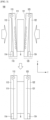
- FIG. 3 is a schematic diagram illustrating a structure and an operating state of a battery cell pressure jig according to an exemplary embodiment of the present invention, with the top view showing a press release state and the bottom view showing a press application state, and
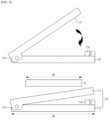
- FIG. 4 is a schematic diagram of a first pressure block.
- the battery cell pressure jig 100 includes a first pressure block 110 and a second pressure block 120 pressing both sides of the battery cell with the battery cell B interposed therebetween,
- the upper part of the pressure plates and the support plates refers to a part corresponding to the gas pocket part, which is the upper part of the battery cell
- the lower part of the pressure plates and the support plates refers to a part corresponding to the part where the electrode assembly is accommodated, which is the lower part of the battery cell.
- the elastic members 114, 124 are coupled to the lower part of the pressure plates 111, 121 or the support plates 112, 122, in the pressure release state, the space between the lower part of the pressure plates 111, 121 and the lower part of the support plates 112, 122 is spaced apart as much as the height H of the elastic members 114, 124.
- the pressure plates 111, 121 and the support plates 112, 122 are each provided with hinge members 113, 123 at their upper edge portions and these (the pressure plates and the support plates) are coupled by the hinge members, there is almost no separation between the upper part of the pressure plates and the upper part of the support plates.
- the separation distance between the pressure plates 111, 121 and the support plates 112, 122 gradually increases from the upper part to the lower part (y-axis direction).
- the separation distance between the pressure plates 111, 121 and the battery cell B gradually decreases from the upper part to the lower part (y-axis direction).
- the battery cell pressure jig 100 of the present invention can pressurize the battery cell from the lower part toward the upper part of the battery cell, it is easy for the gas to move to the gas pocket part of the upper part during pressurization, and accordingly, there is an effect of effectively preventing the gas trap phenomenon.
- the pressure jig 100 of the present invention has a structure in which the first pressure block 110 and the second pressure block 120 facing each other in pairs press both sides of the battery cell B interposed therebetween.
- the structures of the first pressure block 110 and the second pressure block 120 are the same, and there is only a difference in that the regions where they press the battery cell face each other.
- the pressure block 110 is hinged by a hinge member 113 such that the two plates 111, 112 are mutually foldable.
- the pressure plate 111 presses the battery cell by directly facing any one surface of the battery cell B, and the support plate 112 absorbs the reaction force when the pressure plate 111 presses the battery cell B.
- a hinge member 113 is provided at the upper edge portions of the pressure plate 111 and the support plate 112. By the hinge member 113, the pressure plate 111 and the support plate 112 are hinged to each other to be mutually foldable. And it is configured to pressurize the battery cell B located between the first pressure block 110 and the second pressure block 120 in a state in which the pressure plate 111 and the support plate 112 are mutually folded.
- the pressure plate 111 may be a flat-type and made of a strong material to pressurize the battery cell B.
- the pressure plate 111 may be a metal material, and among them, it may be made of an aluminum material. However, it is not limited thereto, and may be made of a heat-resistant and hard plastic material.
- a heating coil (not shown) may be built into the pressure plate 111 to heat the pressure plate 111.
- the pressure plate 111 is preferably a material having an excellent thermal conductivity.
- the support plate 112 serves to support the pressure plate 111, its shape may be a flat-type, which is the same as that of the pressure plate 111, and its size may be the same as the pressure plate 111 or slightly larger than the pressure plate 111.
- the support plate 112 may be made of a material that supports the pressure plate 111 so that the pressure plate 111 can press the battery cell B well and has sufficient rigidity to withstand the reaction force during pressurization.
- a typical example of such a material is a metal material, and specifically, an aluminum material. However, it is not limited thereto, and it may be made of a plastic material.
- the elastic member 114 may be coupled to an upper surface of a lower edge portion of the support plate 112.
- the upper surface means one surface facing the pressure plate 111 among both surfaces of the support plate 112.
- the lower surface of the lower part of the pressure plate 111 can be in face-to-face contact with the elastic member 114.
- the lower surface of the pressure plate 111 means one surface facing the support plate 112 among both surfaces of the pressure plate 111.
- the lower part of the pressure plate 111 may be located at a distance apart from the lower part of the support plate 112 at least by the height H of the elastic member 114.
- the elastic member 114 absorbs the reaction force generated during battery cell pressurization, and is compressed as shown in the bottom view of FIG. 3 .
- the separation between the lower part of the pressure plate 111 and the lower part of the support plate 112 gradually becomes closer, and the pressure plate 111, which has been tilted with respect to the support plate 112, gradually becomes parallel to the support plate 112. Accordingly, the pressure plate 111 can sequentially press from the lower part of the battery cell B to the upper part of the battery cell B.
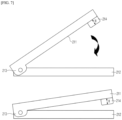
- FIG. 3 and FIG. 4 illustrate examples in which the elastic member 114 is coupled to the upper surface of the lower part of the support plate 112, but as shown in FIG. 7 , the elastic member may be coupled to the lower surface of the lower part of the pressure plate 111.
- the first pressure block includes a flat-type pressure plate 211 that faces and presses the battery cell; a support plate 212 supporting the pressure plate 211 when the pressure plate 211 presses the battery cell; a hinge member 213 provided at the upper edge portions of the pressure plate 211 and the support plate 212 so that the pressure plate 211 and the support plate 212 are mutually foldable; and an elastic member 214 coupled to the lower part of the pressure plate 211, and is compressed when the battery cell is pressed.
- the elastic members 114, 124 may be an elastic spring or a memory foam, and compared to the elastic spring, the memory foam can be more easily coupled to the pressure plate 111 or the support plate 212, and the memory foam is more preferable in that it has an excellent ability to absorb the reaction force generated during battery cell B pressurization.
- the material of the memory foam is not limited, and specifically, it may be a polyurethane-based material.
- the elastic members 114, 214 may be attached and coupled to the pressure plate 111 or the support plate 212 by an adhesive material or a double-sided tape.
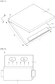
- FIG. 5 is a perspective view of a first pressure block 110 according to an exemplary embodiment of the present invention, and referring to FIG. 5 , the elastic member is a memory foam, has a bar shape, and a thin elastic member extends along the longitudinal direction (x-axis direction) of the support plate.
- the elastic member is a memory foam, has a bar shape, and a thin elastic member extends along the longitudinal direction (x-axis direction) of the support plate.
- the height H of the elastic member may be set to an appropriate height depending on the material, the modulus of elasticity, and the pressing force of the battery cell, and specifically, it may be 1 to 30mm, 3 to 20mm, and 5 to 10mm, but is not limited thereto.
- the width thereof may be 3 to 50mm, 5 to 30mm, and 15 to 25mm, but is not limited thereto.
- the full width W1 of each of the pressure plate and the support plate may be greater than the full width W2 of the battery cell.
- the full width of each of the pressure plate and the support plate refers to a length corresponding to the full width W2 of the battery cell indicated by W1
- the full width of the battery cell refers to a length indicated by W2, and specifically, it is the width of the battery cell in the direction (y-axis direction) from the region where the electrode assembly is accommodated to the gas pocket part.
- the entire surface of the battery cell B can be stably pressed when the full width W1 of each of the pressure plate 111 and the support plate 112 is longer than the full width W2 of the battery cell B.
- the full width W1 of each of the pressure plate and the support plate may be 110% to 200%, 115% to 180%, and 120% to 150% of the full width W2 of the battery cell.
- the battery cell pressure jig according to the present invention can sequentially press from the lower part to the upper part of the battery cell, and as shown in FIG. 6 , gas generated during the formation process or bubbles in the electrolyte can be easily moved from the electrode assembly 1 to the gas pocket part 2, so that it can suppress the bubbles or the gas from being trapped inside the electrode assembly.
- FIG. 8 is a schematic diagram of a battery cell pressure jig according to the second exemplary embodiment of the present invention.
- the battery cell pressure jig 300 according to the second exemplary embodiment includes a first pressure block 310 and a second pressure block 320 that press both sides of the battery cell with the battery cell interposed therebetween.
- the first and second pressure blocks 310, 320 respectively include:
- the guide members 315, 325 are interposed between the lower edge portions of the pressure plates 311, 321 and the lower part of the battery cell.
- the guide members 315, 325 face the elastic members 314, 324 with the pressure plates 311, 321 interposed therebetween. That is, the elastic members 314, 324 and the guide members 315, 325 have a structure that can face each other with the pressure plates 311, 321 interposed therebetween.
- the guide members 315, 325 may be elastic springs or memory foams, preferably memory foams.
- the memory foam can be more easily coupled to the pressure plates 311, 321, and it is more preferable in that it has an excellent ability to absorb the reaction force generated during battery cell B pressurization.
- the memory foam has no limit in its material as long as it is a material with an excellent elastic restoring force, and specifically, it may be a polyurethane-based material.
- the guide members 315, 325 may be coupled to the upper surfaces of the lower edge portions of the pressure plates 311, 321, or may be simply interposed between the lower edge portions of the pressure plates 311, 321 and the lower part of the battery cell B. In this case, the guide members 315, 325 are interposed between the pressure plate 311, 321 and the battery cell B to be in close contact with the sealing surplus part 3 in the lower part of the battery cell.
- the pressure jig 300 of the present invention presses the battery cell B in a state where the battery cell B is interposed between the first pressure block 310 and the second pressure block 320, and in the lower part of the battery cell B, there is a sealing surplus part 3.
- the sealing surplus part 3 is a part where two layers of pouch sheets are sealed and is thinner than the part where the electrode assembly is accommodated, so that a step occurs on a boundary between the electrode assembly accommodating part and the sealing surplus part.
- the guide members 315, 325 serve to guide the battery cell B to be in the correct position so that the electrode assembly accommodating part of a stepped battery cell B does not go down any further than the guide members 315, 325.
- the guide members 315, 325 also have an effect of buffering the sealing surplus part and its surroundings during pressurization. As the pressure plates 311, 321 pressurize the battery cell B, most of the internal gas may move toward the gas pocket part of the upper part of the battery cell, but some of the internal gas may move to the sealing surplus part 3 in the lower part.
- the sealing surplus part 3 is a part where two layers of pouch sheets are fuse-bonded and sealed, and micropores may exist inside the sealing surplus part, and if gas suddenly flows into the micropores, the sealing surplus part 3 cannot overcome the pressure of the flowing gas, so the pouch of the sealing surplus part 3 may be partially damaged.
- the guide members 315, 325 are in close contact with the sealing surplus part 3, even if some of the internal gas tries to flow into the sealing surplus part 3 due to pressurization of the battery cell, it is difficult for the internal gas to flow into the sealing surplus part 3 since the guide members 315, 325 apply an external force to the sealing surplus part 3, allowing it to move to the electrode assembly accommodating part.
- the gas that may remain around the sealing surplus part 3 can also move upward due to the compressive stress generated when the guide member is compressed, thereby further maximizing the effect of the present invention.
- the battery cell pressure jig according to the second exemplary embodiment is only different from the first exemplary embodiment in that it further includes a guide member, and since the rest of the technical details are the same, further detailed description will be omitted.
- the present invention provides a degassing method capable of sequentially pressurizing the battery cell from the lower part to the upper part of the battery cell using such a pressure jig.
- a battery cell to which the pressure jig and the degassing method of the present invention is applied, is manufactured by accommodating an electrode assembly having a positive electrode/separation membrane/negative electrode structure in a battery case, injecting an electrolyte, and sealing the battery cell.
- an electrode mixture containing an electrode active material and a binder is applied to an electrode current collector to prepare a positive electrode and a negative electrode, respectively, and then an electrode assembly is prepared by interposing a separation membrane between the positive electrode and the negative electrode.
- a step of assembling such a battery is not particularly limited and can be performed according to a known method.
- the electrode assembly is not particularly limited as long as it has a structure including a positive electrode, a negative electrode and a separation membrane interposed between the positive electrode and the negative electrode, and may be, for example, a jelly-roll type, a stack type, or a stack/fold type.
- the battery case is not particularly limited as long as it is used as an exterior material for packaging the battery, and a cylindrical, a prismatic, or a pouch type may be used, but in detail, a pouch type battery case may be used.
- the pouch type battery case is usually made of an aluminum laminate sheet, and may be composed of an inner sealant layer for sealing, a metal layer for preventing penetration of substances, and an outer resin layer forming the outermost part of the case.
- the battery cell is manufactured by heat-sealing the upper case and the lower case in a state in which the electrode lead is drawn out after the electrode assembly is accommodated in the pouch-type battery case, and a heat-sealing part may be formed at the end of the battery case.
- a heat-sealing part may be formed at the end of the battery case.
- the positive electrode includes a positive electrode current collector and a positive electrode active material layer prepared by applying, drying, and pressing a positive electrode mixture slurry on the positive electrode current collector.
- the positive electrode mixture includes a positive electrode active material and a binder, and, if necessary, may further include a positive electrode additive, a conductive material, and a filler.
- the positive electrode active material is a compound capable of reversible intercalation and deintercalation of lithium, and specifically, may include a lithium composite metal oxide containing lithium and one or more metals such as cobalt, manganese, nickel, or aluminum. More specifically, the lithium composite metal oxide is a lithium-manganese-based oxide (e.g., LiMnO 2 , LiMn 2 O 4 , etc.), a lithium-cobalt-based oxide (e.g., LiCoO 2 , etc.), a lithium-nickel-based oxide (e.g., LiNiO 2 , etc.), a lithium-nickel-manganese-based oxide (e.g., LiNi 1-Y Mn Y O 2 (where 0 ⁇ Y ⁇ 1), LiMn 2-z Ni z O 4 (where 0 ⁇ Z ⁇ 2), a lithium-nickel-cobalt-based oxide (e.g., LiNi 1-Y1 Co Y1 O 2 (where 0 ⁇ Y1
- the lithium composite metal oxide may be LiCoO 2 , LiMnO 2 , LiNiO 2 , lithium nickel manganese cobalt oxide (e.g., Li(Ni 0.6 Mn 0.2 Co 0.2 )O 2 , Li(Ni 0.5 Mn 0.3 Co 0.2 )O 2 , or Li(Ni 0.8 Mn 0.1 Co 0.1 )O 2 , etc.), or lithium nickel cobalt aluminum oxide (e.g., Li(Ni 0.8 Co 0.15 Al 0.05 )O 2 , etc.), and considering the remarkableness of improvement effect by controlling the type and content ratio of constituent elements forming the lithium composite metal oxide, the lithium composite metal oxide may be Li(Ni 0.6 Mn 0.2 Co 0.2 )O 2 , Li(Ni 0.5 Mn 0.3 Co 0.2 )O 2 , Li(Ni 0.7 Mn 0.15 Co 0.15 )O 2 or Li(Ni 0.8 M
- the content of the positive electrode active material may be 85 to 99 parts by weight, specifically 88 to 98 parts by weight, 90 to 97 parts by weight, or 92 to 95 parts by weight with respect to 100 parts by weight of the positive electrode mixture.
- the conductive material may be used to improve performance such as electrical conductivity of the positive electrode, and may use one or more selected from the group consisting of natural graphite, artificial graphite, carbon black, acetylene black, ketjen black, and carbon fiber.
- the conductive material may include acetylene black.
- the conductive material may be included in an amount of 1 to 10 parts by weight, specifically 2 to 8 parts by weight, or 2 to 6 parts by weight with respect to 100 parts by weight of the mixture layer.
- the binder may include one or more resin selected from the group consisting of polyvinylidene fluoride-hexafluoropropylene copolymer (PVDF-co-HFP), polyvinylidene fluoride, polyacrylonitrile, polymethylmethacrylate, and copolymers thereof.
- the binder may include polyvinylidene fluoride.
- the binder may be included in an amount of 1 to 10 parts by weight, specifically 1 to 8 parts by weight, or 1 to 6 parts by weight with respect to 100 parts by weight of the total mixture.
- the average thickness of the mixture layer is not particularly limited, but may be specifically 50 ⁇ m to 300 ⁇ m, more specifically 100 ⁇ m to 200 ⁇ m; 80 ⁇ m to 150 ⁇ m; 120 ⁇ m to 170 ⁇ m; 150 ⁇ m to 300 ⁇ m; 200 ⁇ m to 300 ⁇ m; or may be 150 ⁇ m to 190 ⁇ m.
- the positive electrode may be used as a current collector that has a high conductivity without causing chemical change in the battery.
- a current collector that has a high conductivity without causing chemical change in the battery.
- stainless steel, aluminum, nickel, titanium, calcined carbon, etc. may be used, and in the case of aluminum or stainless steel, those whose surfaces are treated with carbon, nickel, titanium, silver, or the like may be used.
- the current collector may form micro-scaled irregularities on the surface to increase the adhesive strength of the positive electrode active material, and various forms such as films, sheets, foils, nets, porous materials, foams, and nonwoven fabrics are possible.
- the average thickness of the current collector may be appropriately applied in the range of 3 to 500 ⁇ m in consideration of the conductivity and the total thickness of the positive electrode to be manufactured.
- the negative electrode of the lithium secondary battery used in the present invention is prepared by applying, drying, and pressing the negative electrode active material on the negative electrode current collector, and, if necessary, the same conductive material, organic binder polymer, additives, etc. as in the positive electrode may be optionally further included.
- the negative electrode active material for example, graphite having a completely layered crystal structure such as natural graphite, soft carbon having a low crystalline layered crystal structure (graphene structure; a structure in which hexagonal honeycomb-shaped planes of carbon are arranged in layers), and carbon and graphite materials such as hard carbon, artificial graphite, expanded graphite, carbon fiber, non-graphitizable carbon, carbon black, carbon nanotube, fullerene, and activated carbon in which these structures are mixed with amorphous parts; metal composite oxides such as LixFe 2 O 3 (0 ⁇ x ⁇ 1), LixWO 2 (0 ⁇ x ⁇ 1), SnxMe1-xMe'yOz (Me: Mn, Fe, Pb, Ge; Me': Al, B, P, Si, elements of groups 1, 2, and 3 of the periodic table, halogens; 0 ⁇ x ⁇ 1;1 ⁇ y ⁇ 3; 1 ⁇ z ⁇ 8), and etc.; lithium metals, lithium alloys; tin-based alloy
- the negative electrode may include both graphite and silicon (Si)-containing particles
- the graphite may include any one or more of natural graphite having a layered crystal structure and artificial graphite having an isotropic structure
- the silicon (Si)-containing particles are particles containing silicon (Si) as a main component as a metal component, which may include silicon (Si) particles, SiO particles, SiO 2 particles, or a mixture of one or more of these particles.
- the negative electrode active material may include 80 to 95 parts by weight of graphite; and 1 to 20 parts by weight of silicon (Si)-containing particles with respect to 100 parts by weight of the total.
- the present invention may improve the charge capacity per unit mass while reducing lithium consumption and irreversible capacity loss during the initial charge and discharge of the battery by adjusting the content of graphite and silicon (Si)-containing particles included in the negative electrode active material within the above ranges.
- the negative electrode mixture layer may have an average thickness of 100 ⁇ m to 200 ⁇ m, specifically 100 ⁇ m to 180 ⁇ m, 100 ⁇ m to 150 ⁇ m, 120 ⁇ m to 200 ⁇ m, 140 ⁇ m to 200 ⁇ m, or 140 ⁇ m to 160 ⁇ m.
- the negative electrode current collector is not particularly limited as long as it has a high conductivity without causing chemical change in the battery, and for example, copper, stainless steel, nickel, titanium, baked carbon, etc. can be used, and in the case of copper or stainless steel, those whose surfaces are treated with carbon, nickel, titanium, silver, or the like may be used.
- the negative electrode current collector may form micro-scaled irregularities on the surface to increase the adhesive strength of the negative electrode active material, and various forms such as films, sheets, foils, nets, porous materials, foams, and nonwoven fabrics are possible.
- the average thickness of the negative electrode current collector may be appropriately applied in the range of 3 to 500 ⁇ m in consideration of the conductivity and total thickness of the negative electrode to be manufactured.
- the separation membrane is interposed between the positive electrode and the negative electrode, and an insulating thin film having a high ion permeability and a high mechanical strength is used.
- the separation membrane is not particularly limited as long as it is commonly used in the art, but specifically, a chemically resistant and hydrophobic polypropylene; a glass fiber; or a sheet or a non-woven fabric made of polyethylene may be used, and in some cases, a composite separation membrane in which inorganic particles/organic particles are coated with an organic binder polymer may be used on a porous polymer substrate such as the sheet or the non-woven fabric.
- a solid electrolyte such as a polymer
- the solid electrolyte may serve as the separation membrane.
- the average pore diameter of the separation membrane is 0.01 to 10 ⁇ m, and the average thickness is 5 to 300 ⁇ m.
- the electrolyte may include an organic solvent, a lithium salt, and an additive.
- the organic solvent is not limited as long as decomposition due to an oxidation reaction or the like can be minimized during the charging and discharging process of the battery, and for example, it may be a cyclic carbonate, a linear carbonate, an ester, an ether, or a ketone, etc. These may be used alone, or two or more may be used in combination.
- carbonate-based organic solvents may be preferably used, and examples of cyclic carbonates include ethylene carbonate (EC), propylene carbonate (PC), and butylene carbonate (BC), and representative examples of linear carbonates include dimethyl carbonate (DMC), diethyl carbonate (DEC), dipropyl carbonate (DPC), ethyl methyl carbonate (EMC), methyl propyl carbonate (MPC), and ethyl propyl carbonate (EPC).
- DMC dimethyl carbonate
- DEC diethyl carbonate
- DPC dipropyl carbonate
- EMC ethyl methyl carbonate
- MPC methyl propyl carbonate
- EPC ethyl propyl carbonate
- lithium salts commonly used in electrolytes of lithium secondary batteries such as LiPF 6 , LiAsF 6 , LiCF 3 SO 3 , LiN(CF 3 SO 2 ) 2 , LiBF 4 , LiBF 6 , LiSbF 6 , LiN(C 2 F 5 SO 2 ) 2 , LiAlO 4 , LiAlCl 4 , LiSO 3 CF 3 , and LiClO 4 may be used without limitation, and these may be used alone, or two or more may be used in combination.
- the electrolyte further includes an additive, for example, as the additive, in order to stably form an SEI film, any one selected from the group consisting of vinyl ethylene carbonate, fluoroethylene carbonate, cyclic sulfite, saturated sultone, unsaturated sultone, acyclic sulfone, lithium oxalyl difluoroborate (LiODFB), and derivatives thereof, or a mixture of two or more thereof may be used, but is not limited thereto.
- an additive for example, as the additive, in order to stably form an SEI film, any one selected from the group consisting of vinyl ethylene carbonate, fluoroethylene carbonate, cyclic sulfite, saturated sultone, unsaturated sultone, acyclic sulfone, lithium oxalyl difluoroborate (LiODFB), and derivatives thereof, or a mixture of two or more thereof may be used, but is not limited thereto.
- LiODFB lithium
- the battery cell degassing method according to the present invention includes a process of pressurizing the battery cell using the above-described battery cell pressure jig and a process of discharging the gas inside the battery cell to the outside.
- the process of pressurizing the battery cell may be performed once, or may be repeated 2 to 5 times. Since the pressurization method according to the present invention uses the above-described pressure jig, when pressurizing the battery cell, it is possible to pressurize sequentially from the lower part of the battery cell to the upper part direction where the gas pocket part is located, and thus the gas generated during the formation process may move from the lower part toward the upper part where the gas pocket part is located with directionality.
- the gas inside the battery cell is discharged through a subsequent gas discharge process.
- various techniques known at the filing time of the present invention may be employed.
- the degassing process may be performed by cutting the extended part and sealing the part that is cut, or a process of discharging internal gas to the outside may be performed in a vacuum by forming a through-hole in the gas pocket part.
- this degassing technique is widely known to those skilled in the art, a detailed description thereof will be omitted.
Landscapes
- Chemical & Material Sciences (AREA)
- Chemical Kinetics & Catalysis (AREA)
- Electrochemistry (AREA)
- General Chemical & Material Sciences (AREA)
- Engineering & Computer Science (AREA)
- Manufacturing & Machinery (AREA)
- Secondary Cells (AREA)
- Battery Mounting, Suspending (AREA)
- Gas Exhaust Devices For Batteries (AREA)
Abstract
Description
- This application claims the benefit of a priority based on
Korean Patent Application No. 10-2021-0150241, filed on November 04, 2021 - The present invention relates to a pressure jig of a battery cell and a method for removing residual gas inside a battery cell using the same.
- Generally, secondary batteries can be classified into cylindrical, prismatic, pouch-type, etc. depending on its shape. Among them, the pouch-type secondary battery, because its exterior is made up of exterior materials that is composed of a metal layer(foil) and a synthetic resin multilayer that is coated on the lower and upper surface of the metal layer, allows light weighting of a battery by significantly reducing the weight of the battery compared to a cylindrical or a prismatic battery which uses a metal can. A pouch-type battery is also drawing a lot of attention by having an advantage of being able to change into diverse forms.
- Such pouch-type secondary battery is stored with an electrode assembly in a layered form. The electrode assembly is connected with an electrode tab and an electrode lead, and the electrode lead is protruded from the pouch exterior material. Such electrode lead is supplied with electric power from external device by being electrically connected to the external device through contact.
- A pouch-type secondary battery is manufactured through a process of assembling the cell and activating the battery, and in the battery activation process, the secondary battery cell is loaded to an apparatus for charging and discharging, then the charging-discharging is carried out under necessary conditions for a battery activation. As such, the process of carrying out charging-discharging using the apparatus for charging and discharging for the battery activation is called a formation process.
- In addition, during the formation process, both sides of the battery cell may be pressed using a means of pressurization such as a jig including a flat-type pressure plate during activation charging, which is also referred to as a jig formation. This jig formation prevents the expansion of a negative electrode during the activation process, induces gas generation by promoting chemical reaction of the battery, and moves the internal gas to a gas pocket part.
-
FIG. 1 illustrates a conventional press jig for pressurizing a battery during the formation process, andFIG. 2 illustrates problems that may arise when the formation process is performed using the conventional press jig. Referring toFIG. 1 , a conventional press jig may include multiple pressure plates, and it is configured to press both surfaces of a battery cell in a state where the battery cell B is interposed between thepressure plate 11 and theother pressure plate 12. The pressurization by the pressure jig may be repeated 2 to 3 times, and the gas generated during the formation process moves to the gas pocket part at the upper part of the battery cell by the jig pressurization. Then, as shown inFIG. 2 , a degassing process is performed in which a hole is drilled in the gas pocket part and a vacuum is applied in order to discharge the internal gas collected in the gas pocket part to the outside of the pouch. - However, even after going through the pressing and the degassing processes by the pressure jig, some gas may remain in a negative electrode, between the negative electrode and a separation membrane, between a positive electrode and the separation membrane, and in the positive electrode. This is because the pressure plate that presses the battery cell has a flat shape and presses the entire surface of the battery cell at once, making it difficult for gas to move. Therefore, it is necessary to develop a technology for a new pressing means and a gas discharging method for reducing the amount of gas remaining inside the battery cell.
- The present invention has been made to solve the above problems, and it is directed to provide a pressing mean and a gas removal method having a novel structure in which the gas inside is easily moved to a gas pocket part when a battery cell is pressurized.
- A battery cell pressure jig includes: a first pressure block and a second pressure block pressurizing both sides of a battery cell with the battery cell interposed therebetween, and each of the first pressure block and the second pressure block includes: a flat-type pressure plate that faces and presses the battery cell; a support plate supporting the pressure plate when the pressure plate presses the battery cell; hinge members provided at upper edge portions of the pressure plate and the support plate so that the pressure plate and the support plate are mutually foldable; and an elastic member coupled to a lower part of either the pressure plate or the support plate, and is compressed when the battery cell is pressed.
- The pressure jig according to one exemplary embodiment of the present invention is configured to press the battery cell in a state in which the pressure plate and the support plate are mutually folded.
- In one exemplary embodiment of the present invention, an elastic member is coupled to an upper surface of a lower edge portion of the support plate.
- In one exemplary embodiment of the present invention, the elastic member is coupled to a lower surface of a lower edge portion of the pressure plate.
- In one exemplary embodiment of the present invention, the elastic member may be an elastic spring or a memory foam, preferably a memory foam.
- In one exemplary embodiment of the present invention, the elastic member is attached to either the pressure plate or the support plate by an adhesive material or a double-sided tape.
- In one exemplary embodiment of the present invention, a full width of each of the pressure plate and the support plate is greater than a full width of the battery cell.
- In one exemplary embodiment of the present invention, a full width of each of the pressure plate and the support plate is 110% to 200% of a full width of the battery cell.
- The pressure jig according to one exemplary embodiment of the present invention further includes a guide member for guiding the battery cell to be aligned, and the guide member is interposed between a lower edge portion of the pressure plate and a lower portion of the battery cell.
- In one exemplary embodiment of the present invention, the guide member is an elastic spring or a memory foam.
- In one exemplary embodiment of the present invention, the pressure plate has a built-in heating coil.
- The battery cell degassing method according to the present invention includes: a pressurization process of pressing the battery cell using the battery cell pressure jig; and a gas discharge process of discharging the gas inside the battery cell to the outside.
- The battery cell pressure jig of the present invention has the elastic member provided at the lower edge portion of the support plate for supporting the pressure plate, and as pressure is sequentially applied to the battery cell from the lower portion to the upper portion of the battery cell, making it easy for the gas to move into the gas pocket part of the upper portion with directionality, thereby having an effect of suppressing the gas trap phenomenon in which gas is trapped inside the electrode assembly.
- Since the degassing method of the present invention degasses gas after moving the internal gas to the gas pocket part using the pressure jig, it is possible to minimize gas remaining inside the battery cell.
-
-
FIG. 1 is a schematic diagram of a conventional battery cell pressure jig. -
FIG. 2 is a conceptual diagram illustrating problems that may arise when formation process is performed using a conventional battery cell pressure jig. -
FIG. 3 is a schematic diagram illustrating a structure and an operating state of a battery cell pressure jig according to an exemplary embodiment of the present invention. -
FIG. 4 is a schematic diagram of a first pressure block according to an exemplary embodiment of the present invention. -
FIG. 5 is a perspective view of a first pressure block according to an exemplary embodiment of the present invention. -
FIG. 6 is a schematic diagram of a battery cell pressurized by the pressure jig of the present invention. -
FIG. 7 is a schematic diagram of a first pressure block according to another exemplary embodiment of the present invention. -
FIG. 8 is a schematic diagram illustrating a structure and an operating state of a battery cell pressure jig according to another exemplary embodiment of the present invention. -
- B: BATTERY CELL
- 100, 200, 300: PRESSURE JIG
- 110, 310: FIRST PRESSURE BLOCK
- 120, 320: SECOND PRESSURE BLOCK
- 111, 121, 211, 221, 311, 321: PRESSURE PLATE
- 112, 122. 212. 222, 312, 322: SUPPORT PLATE
- 113, 123, 213, 223, 313, 323: HINGE MEMBER
- 114, 124, 214, 224, 314, 324: ELASTIC MEMBER
- 315, 325: GUIDE MEMBER
- 1: ELECTRODE ASSEMBLY ACCOMMODATING PART
- 2: GAS POCKET PART
- 3: SEALING SURPLUS PART
- The present invention may have various modifications and various examples, thereby specific examples are illustrated in the drawings and described in detail in the detailed description. However, it should be understood that the present invention is not limited to specific embodiments, and includes all modifications, equivalents or alternatives within the spirit and technical scope of the present invention.
- The terms "comprise," "include" and "have" used herein to designate the presence of characteristics, numbers, steps, actions, components, or members described in the specification or a combination thereof, and it should be understood that the possibility of the presence or addition of one or more other characteristics, numbers, steps, actions, components, members or a combination thereof is not excluded in advance. In addition, when a part of a layer, a film, a region or a plate is disposed "on" another part, this includes not only a case in which one part is disposed "directly on" another part, but a case in which a third part is interposed therebetween. In contrast, when a part of a layer, a film, a region or a plate is disposed "under" another part, this includes not only a case in which one part is disposed "directly under" another part, but a case in which a third part is interposed therebetween. In addition, in this application, "on" may include not only a case of disposed on an upper part but also a case of disposed on a lower part.
-
FIG. 3 is a schematic diagram illustrating a structure and an operating state of a battery cell pressure jig according to an exemplary embodiment of the present invention, with the top view showing a press release state and the bottom view showing a press application state, andFIG. 4 is a schematic diagram of a first pressure block. - Referring to
FIG. 3 andFIG. 4 , the batterycell pressure jig 100 according to the present invention includes afirst pressure block 110 and a second pressure block 120 pressing both sides of the battery cell with the battery cell B interposed therebetween, - Each of the
first pressure block 110 and thesecond pressure block 120 includes: flat-type pressure plates -
Support plates pressure plates pressure plates -
Hinge members pressure plates support plates -
Elastic members pressure plates support plates - Here, the upper part of the pressure plates and the support plates refers to a part corresponding to the gas pocket part, which is the upper part of the battery cell, and the lower part of the pressure plates and the support plates refers to a part corresponding to the part where the electrode assembly is accommodated, which is the lower part of the battery cell.
- In the
pressure jig 100 having such a structure, since theelastic members pressure plates support plates pressure plates support plates elastic members - Meanwhile, since the
pressure plates support plates hinge members - Therefore, as shown in
FIG. 3 , in the pressure release state, the separation distance between thepressure plates support plates pressure plates - Accordingly, when the
pressure plates pressure plates pressure plates - As described above, since the battery
cell pressure jig 100 of the present invention can pressurize the battery cell from the lower part toward the upper part of the battery cell, it is easy for the gas to move to the gas pocket part of the upper part during pressurization, and accordingly, there is an effect of effectively preventing the gas trap phenomenon. - The
pressure jig 100 of the present invention has a structure in which thefirst pressure block 110 and the second pressure block 120 facing each other in pairs press both sides of the battery cell B interposed therebetween. The structures of thefirst pressure block 110 and thesecond pressure block 120 are the same, and there is only a difference in that the regions where they press the battery cell face each other. - Since the
first pressure block 110 and the second pressure block 120 have the same structure, the pressure block will be described based on the first pressure block. Referring toFIG. 4 , thepressure block 110 is hinged by ahinge member 113 such that the twoplates pressure plate 111 presses the battery cell by directly facing any one surface of the battery cell B, and thesupport plate 112 absorbs the reaction force when thepressure plate 111 presses the battery cell B. - In addition, a
hinge member 113 is provided at the upper edge portions of thepressure plate 111 and thesupport plate 112. By thehinge member 113, thepressure plate 111 and thesupport plate 112 are hinged to each other to be mutually foldable. And it is configured to pressurize the battery cell B located between thefirst pressure block 110 and thesecond pressure block 120 in a state in which thepressure plate 111 and thesupport plate 112 are mutually folded. - The
pressure plate 111 may be a flat-type and made of a strong material to pressurize the battery cell B. Specifically, thepressure plate 111 may be a metal material, and among them, it may be made of an aluminum material. However, it is not limited thereto, and may be made of a heat-resistant and hard plastic material. - Meanwhile, when it is necessary to pressurize the battery cell B at a high temperature, a heating coil (not shown) may be built into the
pressure plate 111 to heat thepressure plate 111. In this case, thepressure plate 111 is preferably a material having an excellent thermal conductivity. - The
support plate 112 serves to support thepressure plate 111, its shape may be a flat-type, which is the same as that of thepressure plate 111, and its size may be the same as thepressure plate 111 or slightly larger than thepressure plate 111. Thesupport plate 112 may be made of a material that supports thepressure plate 111 so that thepressure plate 111 can press the battery cell B well and has sufficient rigidity to withstand the reaction force during pressurization. A typical example of such a material is a metal material, and specifically, an aluminum material. However, it is not limited thereto, and it may be made of a plastic material. - In one specific example, the
elastic member 114 may be coupled to an upper surface of a lower edge portion of thesupport plate 112. Here, the upper surface means one surface facing thepressure plate 111 among both surfaces of thesupport plate 112. - When the
pressure plate 111 is folded toward thesupport plate 112, by having theelastic member 114 coupled to the upper surface of the lower part of thesupport plate 112, the lower surface of the lower part of thepressure plate 111 can be in face-to-face contact with theelastic member 114. Here, the lower surface of thepressure plate 111 means one surface facing thesupport plate 112 among both surfaces of thepressure plate 111. - Here, when no force is applied, the lower part of the
pressure plate 111 may be located at a distance apart from the lower part of thesupport plate 112 at least by the height H of theelastic member 114. - In a state where the battery cell B is not pressurized as such, there is a gap between the lower part of the
pressure plate 111 and the lower part of thesupport plate 112, and the upper part of thepressure plate 111 is coupled to the upper part of thesupport plate 112, so thepressure plate 111 is tilted with respect to thesupport plate 112. - When the battery cell B is pressed in this state, the
elastic member 114 absorbs the reaction force generated during battery cell pressurization, and is compressed as shown in the bottom view ofFIG. 3 .In addition, as theelastic member 114 is compressed, the separation between the lower part of thepressure plate 111 and the lower part of thesupport plate 112 gradually becomes closer, and thepressure plate 111, which has been tilted with respect to thesupport plate 112, gradually becomes parallel to thesupport plate 112. Accordingly, thepressure plate 111 can sequentially press from the lower part of the battery cell B to the upper part of the battery cell B. - Meanwhile,
FIG. 3 andFIG. 4 illustrate examples in which theelastic member 114 is coupled to the upper surface of the lower part of thesupport plate 112, but as shown inFIG. 7 , the elastic member may be coupled to the lower surface of the lower part of thepressure plate 111. - Referring to
FIG. 7 , the first pressure block includes a flat-type pressure plate 211 that faces and presses the battery cell; asupport plate 212 supporting thepressure plate 211 when thepressure plate 211 presses the battery cell; ahinge member 213 provided at the upper edge portions of thepressure plate 211 and thesupport plate 212 so that thepressure plate 211 and thesupport plate 212 are mutually foldable; and anelastic member 214 coupled to the lower part of thepressure plate 211, and is compressed when the battery cell is pressed. - The
elastic members pressure plate 111 or thesupport plate 212, and the memory foam is more preferable in that it has an excellent ability to absorb the reaction force generated during battery cell B pressurization. As long as the material has an excellent elastic restoring force, the material of the memory foam is not limited, and specifically, it may be a polyurethane-based material. - The
elastic members pressure plate 111 or thesupport plate 212 by an adhesive material or a double-sided tape. -
FIG. 5 is a perspective view of afirst pressure block 110 according to an exemplary embodiment of the present invention, and referring toFIG. 5 , the elastic member is a memory foam, has a bar shape, and a thin elastic member extends along the longitudinal direction (x-axis direction) of the support plate. - The height H of the elastic member may be set to an appropriate height depending on the material, the modulus of elasticity, and the pressing force of the battery cell, and specifically, it may be 1 to 30mm, 3 to 20mm, and 5 to 10mm, but is not limited thereto.
- In addition, in the case where the elastic member is a memory foam, the width thereof may be 3 to 50mm, 5 to 30mm, and 15 to 25mm, but is not limited thereto.
- In one specific example, the full width W1 of each of the pressure plate and the support plate may be greater than the full width W2 of the battery cell.
- Here, referring to
FIG. 4 andFIG. 5 , the full width of each of the pressure plate and the support plate refers to a length corresponding to the full width W2 of the battery cell indicated by W1, and the full width of the battery cell refers to a length indicated by W2, and specifically, it is the width of the battery cell in the direction (y-axis direction) from the region where the electrode assembly is accommodated to the gas pocket part. - The entire surface of the battery cell B can be stably pressed when the full width W1 of each of the
pressure plate 111 and thesupport plate 112 is longer than the full width W2 of the battery cell B. In a specific example, the full width W1 of each of the pressure plate and the support plate may be 110% to 200%, 115% to 180%, and 120% to 150% of the full width W2 of the battery cell. - The battery cell pressure jig according to the present invention can sequentially press from the lower part to the upper part of the battery cell, and as shown in
FIG. 6 , gas generated during the formation process or bubbles in the electrolyte can be easily moved from theelectrode assembly 1 to thegas pocket part 2, so that it can suppress the bubbles or the gas from being trapped inside the electrode assembly. -
FIG. 8 is a schematic diagram of a battery cell pressure jig according to the second exemplary embodiment of the present invention. Referring toFIG. 8 , the batterycell pressure jig 300 according to the second exemplary embodiment includes afirst pressure block 310 and a second pressure block 320 that press both sides of the battery cell with the battery cell interposed therebetween. - The first and second pressure blocks 310, 320 respectively include:
- Flat-
type pressure plates -
Support plates pressure plates pressure plates -
Hinge members pressure plates support plates pressure plates support plates -
Elastic members pressure plate support plates -
Guide members - The
guide members pressure plates - Referring to
FIG. 8 , theguide members elastic members pressure plates elastic members guide members pressure plates - The
guide members elastic members pressure plates - The
guide members pressure plates pressure plates guide members pressure plate surplus part 3 in the lower part of the battery cell. - The
pressure jig 300 of the present invention presses the battery cell B in a state where the battery cell B is interposed between thefirst pressure block 310 and thesecond pressure block 320, and in the lower part of the battery cell B, there is a sealingsurplus part 3. The sealingsurplus part 3 is a part where two layers of pouch sheets are sealed and is thinner than the part where the electrode assembly is accommodated, so that a step occurs on a boundary between the electrode assembly accommodating part and the sealing surplus part. - When the battery cell B is inserted between the
first pressure block 310 and the second pressure block 320 to pressurize the battery cell, theguide members guide members - In addition, the
guide members pressure plates surplus part 3 in the lower part. - Meanwhile, the sealing
surplus part 3 is a part where two layers of pouch sheets are fuse-bonded and sealed, and micropores may exist inside the sealing surplus part, and if gas suddenly flows into the micropores, the sealingsurplus part 3 cannot overcome the pressure of the flowing gas, so the pouch of the sealingsurplus part 3 may be partially damaged. However, if theguide members surplus part 3, even if some of the internal gas tries to flow into the sealingsurplus part 3 due to pressurization of the battery cell, it is difficult for the internal gas to flow into the sealingsurplus part 3 since theguide members surplus part 3, allowing it to move to the electrode assembly accommodating part. Therefore, it is possible to prevent damage to the pouch due to a sudden inflow of gas into the sealingsurplus part 3. In addition, the gas that may remain around the sealingsurplus part 3 can also move upward due to the compressive stress generated when the guide member is compressed, thereby further maximizing the effect of the present invention. - The battery cell pressure jig according to the second exemplary embodiment is only different from the first exemplary embodiment in that it further includes a guide member, and since the rest of the technical details are the same, further detailed description will be omitted.
- In addition, the present invention provides a degassing method capable of sequentially pressurizing the battery cell from the lower part to the upper part of the battery cell using such a pressure jig.
- A battery cell, to which the pressure jig and the degassing method of the present invention is applied, is manufactured by accommodating an electrode assembly having a positive electrode/separation membrane/negative electrode structure in a battery case, injecting an electrolyte, and sealing the battery cell.
- Specifically, an electrode mixture containing an electrode active material and a binder is applied to an electrode current collector to prepare a positive electrode and a negative electrode, respectively, and then an electrode assembly is prepared by interposing a separation membrane between the positive electrode and the negative electrode.
- After accommodating the prepared electrode assembly in the battery case, electrolyte is injected, and the battery case is sealed to assemble the battery.
- A step of assembling such a battery is not particularly limited and can be performed according to a known method.
- In addition, the electrode assembly is not particularly limited as long as it has a structure including a positive electrode, a negative electrode and a separation membrane interposed between the positive electrode and the negative electrode, and may be, for example, a jelly-roll type, a stack type, or a stack/fold type.
- Here, the battery case is not particularly limited as long as it is used as an exterior material for packaging the battery, and a cylindrical, a prismatic, or a pouch type may be used, but in detail, a pouch type battery case may be used. The pouch type battery case is usually made of an aluminum laminate sheet, and may be composed of an inner sealant layer for sealing, a metal layer for preventing penetration of substances, and an outer resin layer forming the outermost part of the case. The battery cell is manufactured by heat-sealing the upper case and the lower case in a state in which the electrode lead is drawn out after the electrode assembly is accommodated in the pouch-type battery case, and a heat-sealing part may be formed at the end of the battery case. Hereinafter, detailed descriptions of the battery case are omitted because they are known to those skilled in the art.
- The positive electrode includes a positive electrode current collector and a positive electrode active material layer prepared by applying, drying, and pressing a positive electrode mixture slurry on the positive electrode current collector. The positive electrode mixture includes a positive electrode active material and a binder, and, if necessary, may further include a positive electrode additive, a conductive material, and a filler.
- The positive electrode active material is a compound capable of reversible intercalation and deintercalation of lithium, and specifically, may include a lithium composite metal oxide containing lithium and one or more metals such as cobalt, manganese, nickel, or aluminum. More specifically, the lithium composite metal oxide is a lithium-manganese-based oxide (e.g., LiMnO2, LiMn2O4, etc.), a lithium-cobalt-based oxide (e.g., LiCoO2, etc.), a lithium-nickel-based oxide (e.g., LiNiO2, etc.), a lithium-nickel-manganese-based oxide (e.g., LiNi1-YMnYO2 (where 0<Y<1), LiMn2-zNizO4 (where 0<Z<2), a lithium-nickel-cobalt-based oxide (e.g., LiNi1-Y1CoY1O2 (where 0<Y1<1), a lithium-manganese-cobalt-based oxide (e.g., LiCo1-Y2MnY2O2 (where 0<Y2<1), LiMn2-z1Coz1O4 (where 0<Z1<2), a lithium-nickel-manganese-cobalt-based oxide (e.g., Li(NipCoqMnr1)O2 (where 0<p<1, 0<q<1, 0<r1<1, p+q+r1=1) or Li(Nip1Coq1Mnr2)O4 (where 0<p1<2, 0<q1<2, 0<r2<2, p1+q1+r2=2), etc.), or a lithium-nickel-cobalt-transition metal (M) oxide (e.g., Li(Nip2Coq2Mnr3MS2)O2 (where M is selected from the group consisting of Al, Fe, V, Cr, Ti, Ta, Mg, and Mo, and p2, q2, r3, and s2 are atomic fractions of independent elements where 0<p2<1, 0<q2<1, 0<r3<1, 0<s2<1, p2+q2+r3+s2 = 1, respectively), etc.), and the like, and any one or two or more of these compounds may be included. Among them, in a sense that it can improve the capacity characteristics and stability of the battery, the lithium composite metal oxide may be LiCoO2, LiMnO2, LiNiO2, lithium nickel manganese cobalt oxide (e.g., Li(Ni0.6Mn0.2Co0.2)O2, Li(Ni0.5Mn0.3Co0.2)O2, or Li(Ni0.8Mn0.1Co0.1)O2, etc.), or lithium nickel cobalt aluminum oxide (e.g., Li(Ni0.8Co0.15Al0.05)O2, etc.), and considering the remarkableness of improvement effect by controlling the type and content ratio of constituent elements forming the lithium composite metal oxide, the lithium composite metal oxide may be Li(Ni0.6Mn0.2Co0.2)O2, Li(Ni0.5Mn0.3Co0.2)O2, Li(Ni0.7Mn0.15Co0.15)O2 or Li(Ni0.8Mn0.1Co0.1)O2, etc., and any one of these or a mixture of two or more may be used.
- In addition, the content of the positive electrode active material may be 85 to 99 parts by weight, specifically 88 to 98 parts by weight, 90 to 97 parts by weight, or 92 to 95 parts by weight with respect to 100 parts by weight of the positive electrode mixture.
- The conductive material may be used to improve performance such as electrical conductivity of the positive electrode, and may use one or more selected from the group consisting of natural graphite, artificial graphite, carbon black, acetylene black, ketjen black, and carbon fiber. For example, the conductive material may include acetylene black.
- In addition, the conductive material may be included in an amount of 1 to 10 parts by weight, specifically 2 to 8 parts by weight, or 2 to 6 parts by weight with respect to 100 parts by weight of the mixture layer.
- In addition, the binder may include one or more resin selected from the group consisting of polyvinylidene fluoride-hexafluoropropylene copolymer (PVDF-co-HFP), polyvinylidene fluoride, polyacrylonitrile, polymethylmethacrylate, and copolymers thereof. As an example, the binder may include polyvinylidene fluoride.
- In addition, the binder may be included in an amount of 1 to 10 parts by weight, specifically 1 to 8 parts by weight, or 1 to 6 parts by weight with respect to 100 parts by weight of the total mixture.
- Furthermore, the average thickness of the mixture layer is not particularly limited, but may be specifically 50µm to 300µm, more specifically 100µm to 200µm; 80µm to 150µm; 120µm to 170µm; 150µm to 300µm; 200µm to 300µm; or may be 150µm to 190µm.
- In addition, the positive electrode may be used as a current collector that has a high conductivity without causing chemical change in the battery. For example, stainless steel, aluminum, nickel, titanium, calcined carbon, etc. may be used, and in the case of aluminum or stainless steel, those whose surfaces are treated with carbon, nickel, titanium, silver, or the like may be used. In addition, the current collector may form micro-scaled irregularities on the surface to increase the adhesive strength of the positive electrode active material, and various forms such as films, sheets, foils, nets, porous materials, foams, and nonwoven fabrics are possible. Additionally, the average thickness of the current collector may be appropriately applied in the range of 3 to 500µm in consideration of the conductivity and the total thickness of the positive electrode to be manufactured.
- Moreover, the negative electrode of the lithium secondary battery used in the present invention is prepared by applying, drying, and pressing the negative electrode active material on the negative electrode current collector, and, if necessary, the same conductive material, organic binder polymer, additives, etc. as in the positive electrode may be optionally further included.
- In addition, as the negative electrode active material, for example, graphite having a completely layered crystal structure such as natural graphite, soft carbon having a low crystalline layered crystal structure (graphene structure; a structure in which hexagonal honeycomb-shaped planes of carbon are arranged in layers), and carbon and graphite materials such as hard carbon, artificial graphite, expanded graphite, carbon fiber, non-graphitizable carbon, carbon black, carbon nanotube, fullerene, and activated carbon in which these structures are mixed with amorphous parts; metal composite oxides such as LixFe2O3(0≤x≤1), LixWO2(0≤x≤1), SnxMe1-xMe'yOz (Me: Mn, Fe, Pb, Ge; Me': Al, B, P, Si, elements of groups 1, 2, and 3 of the periodic table, halogens; 0<x≤1;1≤y≤3; 1≤z≤8), and etc.; lithium metals, lithium alloys; tin-based alloys; metal oxides such as SnO, SnO2, PbO, PbO2, Pb2O3, Pb3O4, Sb2O3, Sb2O4, Sb2O5, GeO, GeO2, Bi2O3, Bi2O4, and Bi2O5; conductive polymers such as polyacetylene; Li-Co-Ni-based materials; titanium oxides; lithium titanium oxides, and the like can be used.
- As an example, the negative electrode may include both graphite and silicon (Si)-containing particles, and the graphite may include any one or more of natural graphite having a layered crystal structure and artificial graphite having an isotropic structure, and the silicon (Si)-containing particles are particles containing silicon (Si) as a main component as a metal component, which may include silicon (Si) particles, SiO particles, SiO2 particles, or a mixture of one or more of these particles.
- In this case, the negative electrode active material may include 80 to 95 parts by weight of graphite; and 1 to 20 parts by weight of silicon (Si)-containing particles with respect to 100 parts by weight of the total. The present invention may improve the charge capacity per unit mass while reducing lithium consumption and irreversible capacity loss during the initial charge and discharge of the battery by adjusting the content of graphite and silicon (Si)-containing particles included in the negative electrode active material within the above ranges.
- In addition, the negative electrode mixture layer may have an average thickness of 100µm to 200µm, specifically 100µm to 180µm, 100µm to 150µm, 120µm to 200µm, 140µm to 200µm, or 140µm to 160µm.
- Moreover, the negative electrode current collector is not particularly limited as long as it has a high conductivity without causing chemical change in the battery, and for example, copper, stainless steel, nickel, titanium, baked carbon, etc. can be used, and in the case of copper or stainless steel, those whose surfaces are treated with carbon, nickel, titanium, silver, or the like may be used. In addition, like the positive electrode current collector, the negative electrode current collector may form micro-scaled irregularities on the surface to increase the adhesive strength of the negative electrode active material, and various forms such as films, sheets, foils, nets, porous materials, foams, and nonwoven fabrics are possible. In addition, the average thickness of the negative electrode current collector may be appropriately applied in the range of 3 to 500µm in consideration of the conductivity and total thickness of the negative electrode to be manufactured.
- In addition, the separation membrane is interposed between the positive electrode and the negative electrode, and an insulating thin film having a high ion permeability and a high mechanical strength is used. The separation membrane is not particularly limited as long as it is commonly used in the art, but specifically, a chemically resistant and hydrophobic polypropylene; a glass fiber; or a sheet or a non-woven fabric made of polyethylene may be used, and in some cases, a composite separation membrane in which inorganic particles/organic particles are coated with an organic binder polymer may be used on a porous polymer substrate such as the sheet or the non-woven fabric. When a solid electrolyte such as a polymer is used as the electrolyte, the solid electrolyte may serve as the separation membrane. In addition, the average pore diameter of the separation membrane is 0.01 to 10µm, and the average thickness is 5 to 300µm.
- The electrolyte may include an organic solvent, a lithium salt, and an additive.
- The organic solvent is not limited as long as decomposition due to an oxidation reaction or the like can be minimized during the charging and discharging process of the battery, and for example, it may be a cyclic carbonate, a linear carbonate, an ester, an ether, or a ketone, etc. These may be used alone, or two or more may be used in combination.
- Among the above organic solvents, carbonate-based organic solvents may be preferably used, and examples of cyclic carbonates include ethylene carbonate (EC), propylene carbonate (PC), and butylene carbonate (BC), and representative examples of linear carbonates include dimethyl carbonate (DMC), diethyl carbonate (DEC), dipropyl carbonate (DPC), ethyl methyl carbonate (EMC), methyl propyl carbonate (MPC), and ethyl propyl carbonate (EPC).
- For the lithium salt, lithium salts commonly used in electrolytes of lithium secondary batteries such as LiPF6, LiAsF6, LiCF3SO3, LiN(CF3SO2)2, LiBF4, LiBF6, LiSbF6, LiN(C2F5SO2)2, LiAlO4, LiAlCl4, LiSO3CF3, and LiClO4 may be used without limitation, and these may be used alone, or two or more may be used in combination.
- In addition, the electrolyte further includes an additive, for example, as the additive, in order to stably form an SEI film, any one selected from the group consisting of vinyl ethylene carbonate, fluoroethylene carbonate, cyclic sulfite, saturated sultone, unsaturated sultone, acyclic sulfone, lithium oxalyl difluoroborate (LiODFB), and derivatives thereof, or a mixture of two or more thereof may be used, but is not limited thereto.
- The battery cell degassing method according to the present invention includes a process of pressurizing the battery cell using the above-described battery cell pressure jig and a process of discharging the gas inside the battery cell to the outside.
- The process of pressurizing the battery cell may be performed once, or may be repeated 2 to 5 times. Since the pressurization method according to the present invention uses the above-described pressure jig, when pressurizing the battery cell, it is possible to pressurize sequentially from the lower part of the battery cell to the upper part direction where the gas pocket part is located, and thus the gas generated during the formation process may move from the lower part toward the upper part where the gas pocket part is located with directionality.
- Then, the gas inside the battery cell is discharged through a subsequent gas discharge process. In this gas discharge process, various techniques known at the filing time of the present invention may be employed. For example, in a pouch-type secondary battery with one side extended, the degassing process may be performed by cutting the extended part and sealing the part that is cut, or a process of discharging internal gas to the outside may be performed in a vacuum by forming a through-hole in the gas pocket part. However, since this degassing technique is widely known to those skilled in the art, a detailed description thereof will be omitted.
- As above, the exemplary embodiments of the present invention have been described with reference to diagrams, but it should be understood by those skilled in the art or those of ordinary skill in the art that the present invention can be variously modified and changed without departing from the spirit and technical scope of the present invention described in the accompanying claims.
- Therefore, the technical scope of the present invention is not limited to the contents described in the detailed description of the specification, but should be defined by the claims.
Claims (13)
- A battery cell pressure jig, comprising:a first pressure block and a second pressure block pressurizing both sides of a battery cell with the battery cell interposed therebetween, andeach of the first pressure block and the second pressure block comprises:a flat-type pressure plate that faces and presses the battery cell;a support plate supporting the pressure plate when the pressure plate presses the battery cell;hinge members provided at upper edge portions of the pressure plate and the support plate so that the pressure plate and the support plate are mutually foldable; andan elastic member coupled to a lower part of either the pressure plate or the support plate, and is compressed when the battery cell is pressed.
- The battery cell pressure jig of claim 1, wherein
the battery cell pressure jig is configured to press the battery cell in a state in which the pressure plate and the support plate are mutually folded. - The battery cell pressure jig of claim 1, wherein
the elastic member is coupled to an upper surface of a lower edge portion of the support plate. - The battery cell pressure jig of claim 1, wherein
the elastic member is coupled to a lower surface of a lower edge portion of the pressure plate. - The battery cell pressure jig of claim 1, wherein
the elastic member is an elastic spring or a memory foam. - The battery cell pressure jig of claim 1, wherein
the elastic member is a memory foam. - The battery cell pressure jig of claim 1, wherein
the elastic member is attached to either the pressure plate or the support plate by an adhesive material or a double-sided tape. - The battery cell pressure jig of claim 1, wherein
a full width of each of the pressure plate and the support plate is greater than a full width of the battery cell. - The battery cell pressure jig of claim 1, wherein
a full width of each of the pressure plate and the support plate is 110% to 200% of a full width of the battery cell. - The battery cell pressure jig of claim 1,
further comprises a guide member for guiding the battery cell to be aligned, and the guide member is interposed between a lower edge portion of the pressure plate and a lower portion of the battery cell. - The battery cell pressure jig of claim 10, wherein
the guide member is an elastic spring or a memory foam. - The battery cell pressure jig of claim 1, wherein
the pressure plate has a built-in heating coil. - A battery cell degassing method, comprising:a pressurization process of pressing the battery cell using the battery cell pressure jig of claim 1; anda gas discharge process of discharging gas inside the battery cell to the outside.
Applications Claiming Priority (2)
| Application Number | Priority Date | Filing Date | Title |
|---|---|---|---|
| KR1020210150241A KR102819201B1 (en) | 2021-11-04 | 2021-11-04 | A jig for presurizing a battery cell and a degassing method using the same |
| PCT/KR2022/017068 WO2023080648A1 (en) | 2021-11-04 | 2022-11-02 | Pressurization jig of battery cell and gas removal method using same |
Publications (2)
| Publication Number | Publication Date |
|---|---|
| EP4235890A1 true EP4235890A1 (en) | 2023-08-30 |
| EP4235890A4 EP4235890A4 (en) | 2024-07-17 |
Family
ID=86241859
Family Applications (1)
| Application Number | Title | Priority Date | Filing Date |
|---|---|---|---|
| EP22890379.5A Pending EP4235890A4 (en) | 2021-11-04 | 2022-11-02 | TEMPLATE FOR PRESSURIZING A BATTERY CELL AND METHOD FOR ELIMINATING GAS USING SAME |
Country Status (6)
| Country | Link |
|---|---|
| US (1) | US12586810B2 (en) |
| EP (1) | EP4235890A4 (en) |
| JP (1) | JP7532722B2 (en) |
| KR (1) | KR102819201B1 (en) |
| CN (1) | CN116670877A (en) |
| WO (1) | WO2023080648A1 (en) |
Families Citing this family (2)
| Publication number | Priority date | Publication date | Assignee | Title |
|---|---|---|---|---|
| JP7507192B2 (en) * | 2022-03-23 | 2024-06-27 | プライムプラネットエナジー&ソリューションズ株式会社 | Method for manufacturing an electricity storage device |
| KR102705545B1 (en) * | 2024-02-19 | 2024-09-11 | 주식회사 우원기술 | Tilting gripper for gripping cell stack |
Family Cites Families (16)
| Publication number | Priority date | Publication date | Assignee | Title |
|---|---|---|---|---|
| KR20130044776A (en) | 2011-10-24 | 2013-05-03 | 에스케이이노베이션 주식회사 | Degassing apparatus for battery cell and method of the same |
| KR101571210B1 (en) * | 2013-09-04 | 2015-11-23 | 주식회사 엘지화학 | Jig apparatus for secondary battery |
| KR101910686B1 (en) * | 2014-01-28 | 2018-10-22 | 주식회사 엘지화학 | Apparatus of pressuring battery cell and method of pressuring battery cell using the same |
| CN103811817A (en) | 2014-02-12 | 2014-05-21 | 宁德新能源科技有限公司 | Lithium ion battery hot-press formation clamp |
| KR101747909B1 (en) | 2014-02-13 | 2017-06-15 | 주식회사 엘지화학 | Apparatus for impregnating electrode assembly with electrolyte |
| JP2016091622A (en) * | 2014-10-30 | 2016-05-23 | 株式会社カネカ | Battery pack and power storage unit including the same |
| KR101809689B1 (en) | 2014-11-11 | 2017-12-15 | 주식회사 엘지화학 | Pressing zig for secondary battery cell |
| JP6598245B2 (en) * | 2015-10-23 | 2019-10-30 | 日産自動車株式会社 | Secondary battery manufacturing method and manufacturing apparatus thereof |
| KR102553471B1 (en) | 2016-02-16 | 2023-07-10 | 에스케이온 주식회사 | Pressing apparatus of bettery cell |
| KR102135266B1 (en) * | 2017-02-06 | 2020-07-17 | 주식회사 엘지화학 | Apparatus and method for manufacturing battery cell |
| KR102348775B1 (en) * | 2017-05-31 | 2022-01-06 | 한국전기연구원 | Pressing apparatus for secondary battery cell |
| KR102455541B1 (en) * | 2017-12-15 | 2022-10-14 | 주식회사 엘지에너지솔루션 | Pressing Zig for charging and discharging of pouch-type secondary battery |
| KR102772424B1 (en) * | 2019-08-05 | 2025-02-25 | 주식회사 엘지에너지솔루션 | Degassing apparatus for secondary battery and degassing method for secondary battery using the same |
| JP2021082407A (en) | 2019-11-15 | 2021-05-27 | トヨタ自動車株式会社 | Battery module |
| KR102798481B1 (en) | 2020-01-10 | 2025-04-22 | 주식회사 엘지에너지솔루션 | Pressurized jig for removing gas traps and a method of manufacturing a secondary battery using the same |
| KR20210150241A (en) | 2020-06-03 | 2021-12-10 | 이상하 | A mouthwash containing saponin extracted from ginseng, etc. as the main ingredient. |
-
2021
- 2021-11-04 KR KR1020210150241A patent/KR102819201B1/en active Active
-
2022
- 2022-11-02 EP EP22890379.5A patent/EP4235890A4/en active Pending
- 2022-11-02 JP JP2023530498A patent/JP7532722B2/en active Active
- 2022-11-02 US US18/039,438 patent/US12586810B2/en active Active
- 2022-11-02 WO PCT/KR2022/017068 patent/WO2023080648A1/en not_active Ceased
- 2022-11-02 CN CN202280007533.5A patent/CN116670877A/en active Pending
Also Published As
| Publication number | Publication date |
|---|---|
| EP4235890A4 (en) | 2024-07-17 |
| WO2023080648A1 (en) | 2023-05-11 |
| JP7532722B2 (en) | 2024-08-14 |
| US20230420724A1 (en) | 2023-12-28 |
| US12586810B2 (en) | 2026-03-24 |
| JP2023551803A (en) | 2023-12-13 |
| CN116670877A (en) | 2023-08-29 |
| KR20230064768A (en) | 2023-05-11 |
| KR102819201B1 (en) | 2025-06-11 |
Similar Documents
| Publication | Publication Date | Title |
|---|---|---|
| KR102160701B1 (en) | Electrode with Perforated Current Collector, Lithium Secondary Battery containing the Same | |
| KR101334623B1 (en) | Degassing Method of Secondary Battery Using Centrifugal Force | |
| US10044071B2 (en) | Nonaqueous electrolyte secondary battery and method for manufacturing same | |
| KR101304870B1 (en) | Method for Manufacturing Battery Cell and Battery Cell Manufactured Thereby | |
| CN113795961B (en) | Extrusion jig and method of manufacturing secondary battery using the same | |
| KR102113656B1 (en) | Manufacturing method of secondary battery | |
| KR102586822B1 (en) | Method for manufacturing negative electrode for secondary battery | |
| US12586810B2 (en) | Pressure jig of battery cell and gas removal method using the same | |
| JP6479984B2 (en) | Non-aqueous electrolyte battery and battery pack | |
| EP4053953A1 (en) | Electrode assembly and method for manufacturing same | |
| JP2014179220A (en) | Laminate armored battery | |
| CN112913051B (en) | Secondary battery | |
| JP7266753B2 (en) | Apparatus for prelithiation of negative electrode and method for prelithiation of negative electrode | |
| EP4258410A1 (en) | Method for activating lithium secondary battery | |
| EP4027425A1 (en) | Electrode assembly and method for manufacturing same | |
| JP7409762B2 (en) | Nonaqueous electrolyte secondary battery and method for manufacturing nonaqueous electrolyte secondary battery | |
| US20240063439A1 (en) | Activation method and activation device for lithium secondary battery | |
| JP7430665B2 (en) | Secondary battery current collector and its manufacturing method, and secondary battery | |
| KR20230070812A (en) | Manufacturing method of lithium secondary battery | |
| KR102966117B1 (en) | A method for removing trap gas inside a battery, a method for manufacturing a battery including the same | |
| US20240322216A1 (en) | Method for activation of lithium secondary battery | |
| KR20230060052A (en) | A method for removing trap gas inside a battery, a method for manufacturing a battery including the same | |
| KR102940091B1 (en) | Electrode for lithium secondary battery and manufacturing method thereof | |
| KR20230076771A (en) | Fomation method of lithium secondary battery | |
| JP4654589B2 (en) | Battery pack |
Legal Events
| Date | Code | Title | Description |
|---|---|---|---|
| STAA | Information on the status of an ep patent application or granted ep patent |
Free format text: STATUS: THE INTERNATIONAL PUBLICATION HAS BEEN MADE |
|
| PUAI | Public reference made under article 153(3) epc to a published international application that has entered the european phase |
Free format text: ORIGINAL CODE: 0009012 |
|
| STAA | Information on the status of an ep patent application or granted ep patent |
Free format text: STATUS: REQUEST FOR EXAMINATION WAS MADE |
|
| 17P | Request for examination filed |
Effective date: 20230523 |
|
| AK | Designated contracting states |
Kind code of ref document: A1 Designated state(s): AL AT BE BG CH CY CZ DE DK EE ES FI FR GB GR HR HU IE IS IT LI LT LU LV MC ME MK MT NL NO PL PT RO RS SE SI SK SM TR |
|
| A4 | Supplementary search report drawn up and despatched |
Effective date: 20240617 |
|
| RIC1 | Information provided on ipc code assigned before grant |
Ipc: H01M 10/44 20060101ALI20240611BHEP Ipc: H01M 10/42 20060101ALI20240611BHEP Ipc: H01M 10/04 20060101AFI20240611BHEP |
|
| DAV | Request for validation of the european patent (deleted) | ||
| DAX | Request for extension of the european patent (deleted) | ||
| STAA | Information on the status of an ep patent application or granted ep patent |
Free format text: STATUS: EXAMINATION IS IN PROGRESS |
|
| 17Q | First examination report despatched |
Effective date: 20250212 |