EP4235864A1 - Positive electrode plate, secondary battery, battery module, battery pack, and electronic apparatus - Google Patents
Positive electrode plate, secondary battery, battery module, battery pack, and electronic apparatus Download PDFInfo
- Publication number
- EP4235864A1 EP4235864A1 EP22874234.2A EP22874234A EP4235864A1 EP 4235864 A1 EP4235864 A1 EP 4235864A1 EP 22874234 A EP22874234 A EP 22874234A EP 4235864 A1 EP4235864 A1 EP 4235864A1
- Authority
- EP
- European Patent Office
- Prior art keywords
- active material
- positive electrode
- material layer
- size distribution
- pore size
- Prior art date
- Legal status (The legal status is an assumption and is not a legal conclusion. Google has not performed a legal analysis and makes no representation as to the accuracy of the status listed.)
- Pending
Links
Images


Classifications
-
- H—ELECTRICITY
- H01—ELECTRIC ELEMENTS
- H01M—PROCESSES OR MEANS, e.g. BATTERIES, FOR THE DIRECT CONVERSION OF CHEMICAL ENERGY INTO ELECTRICAL ENERGY
- H01M4/00—Electrodes
- H01M4/02—Electrodes composed of, or comprising, active material
- H01M4/13—Electrodes for accumulators with non-aqueous electrolyte, e.g. for lithium-accumulators; Processes of manufacture thereof
-
- H—ELECTRICITY
- H01—ELECTRIC ELEMENTS
- H01M—PROCESSES OR MEANS, e.g. BATTERIES, FOR THE DIRECT CONVERSION OF CHEMICAL ENERGY INTO ELECTRICAL ENERGY
- H01M10/00—Secondary cells; Manufacture thereof
- H01M10/05—Accumulators with non-aqueous electrolyte
- H01M10/052—Li-accumulators
-
- H—ELECTRICITY
- H01—ELECTRIC ELEMENTS
- H01M—PROCESSES OR MEANS, e.g. BATTERIES, FOR THE DIRECT CONVERSION OF CHEMICAL ENERGY INTO ELECTRICAL ENERGY
- H01M4/00—Electrodes
- H01M4/02—Electrodes composed of, or comprising, active material
- H01M4/36—Selection of substances as active materials, active masses, active liquids
- H01M4/362—Composites
- H01M4/366—Composites as layered products
-
- H—ELECTRICITY
- H01—ELECTRIC ELEMENTS
- H01M—PROCESSES OR MEANS, e.g. BATTERIES, FOR THE DIRECT CONVERSION OF CHEMICAL ENERGY INTO ELECTRICAL ENERGY
- H01M4/00—Electrodes
- H01M4/02—Electrodes composed of, or comprising, active material
- H01M4/13—Electrodes for accumulators with non-aqueous electrolyte, e.g. for lithium-accumulators; Processes of manufacture thereof
- H01M4/133—Electrodes based on carbonaceous material, e.g. graphite-intercalation compounds or CFx
-
- H—ELECTRICITY
- H01—ELECTRIC ELEMENTS
- H01M—PROCESSES OR MEANS, e.g. BATTERIES, FOR THE DIRECT CONVERSION OF CHEMICAL ENERGY INTO ELECTRICAL ENERGY
- H01M4/00—Electrodes
- H01M4/02—Electrodes composed of, or comprising, active material
- H01M4/13—Electrodes for accumulators with non-aqueous electrolyte, e.g. for lithium-accumulators; Processes of manufacture thereof
- H01M4/134—Electrodes based on metals, Si or alloys
-
- H—ELECTRICITY
- H01—ELECTRIC ELEMENTS
- H01M—PROCESSES OR MEANS, e.g. BATTERIES, FOR THE DIRECT CONVERSION OF CHEMICAL ENERGY INTO ELECTRICAL ENERGY
- H01M4/00—Electrodes
- H01M4/02—Electrodes composed of, or comprising, active material
- H01M4/36—Selection of substances as active materials, active masses, active liquids
-
- H—ELECTRICITY
- H01—ELECTRIC ELEMENTS
- H01M—PROCESSES OR MEANS, e.g. BATTERIES, FOR THE DIRECT CONVERSION OF CHEMICAL ENERGY INTO ELECTRICAL ENERGY
- H01M4/00—Electrodes
- H01M4/02—Electrodes composed of, or comprising, active material
- H01M4/36—Selection of substances as active materials, active masses, active liquids
- H01M4/362—Composites
-
- H—ELECTRICITY
- H01—ELECTRIC ELEMENTS
- H01M—PROCESSES OR MEANS, e.g. BATTERIES, FOR THE DIRECT CONVERSION OF CHEMICAL ENERGY INTO ELECTRICAL ENERGY
- H01M4/00—Electrodes
- H01M4/02—Electrodes composed of, or comprising, active material
- H01M4/36—Selection of substances as active materials, active masses, active liquids
- H01M4/38—Selection of substances as active materials, active masses, active liquids of elements or alloys
- H01M4/386—Silicon or alloys based on silicon
-
- H—ELECTRICITY
- H01—ELECTRIC ELEMENTS
- H01M—PROCESSES OR MEANS, e.g. BATTERIES, FOR THE DIRECT CONVERSION OF CHEMICAL ENERGY INTO ELECTRICAL ENERGY
- H01M4/00—Electrodes
- H01M4/02—Electrodes composed of, or comprising, active material
- H01M4/36—Selection of substances as active materials, active masses, active liquids
- H01M4/58—Selection of substances as active materials, active masses, active liquids of inorganic compounds other than oxides or hydroxides, e.g. sulfides, selenides, tellurides, halogenides or LiCoFy; of polyanionic structures, e.g. phosphates, silicates or borates
- H01M4/583—Carbonaceous material, e.g. graphite-intercalation compounds or CFx
- H01M4/587—Carbonaceous material, e.g. graphite-intercalation compounds or CFx for inserting or intercalating light metals
-
- H—ELECTRICITY
- H01—ELECTRIC ELEMENTS
- H01M—PROCESSES OR MEANS, e.g. BATTERIES, FOR THE DIRECT CONVERSION OF CHEMICAL ENERGY INTO ELECTRICAL ENERGY
- H01M4/00—Electrodes
- H01M4/02—Electrodes composed of, or comprising, active material
- H01M4/62—Selection of inactive substances as ingredients for active masses, e.g. binders, fillers
- H01M4/624—Electric conductive fillers
- H01M4/625—Carbon or graphite
-
- H—ELECTRICITY
- H01—ELECTRIC ELEMENTS
- H01M—PROCESSES OR MEANS, e.g. BATTERIES, FOR THE DIRECT CONVERSION OF CHEMICAL ENERGY INTO ELECTRICAL ENERGY
- H01M50/00—Constructional details or processes of manufacture of the non-active parts of electrochemical cells other than fuel cells, e.g. hybrid cells
- H01M50/10—Primary casings; Jackets or wrappings
- H01M50/102—Primary casings; Jackets or wrappings characterised by their shape or physical structure
- H01M50/103—Primary casings; Jackets or wrappings characterised by their shape or physical structure prismatic or rectangular
-
- H—ELECTRICITY
- H01—ELECTRIC ELEMENTS
- H01M—PROCESSES OR MEANS, e.g. BATTERIES, FOR THE DIRECT CONVERSION OF CHEMICAL ENERGY INTO ELECTRICAL ENERGY
- H01M4/00—Electrodes
- H01M4/02—Electrodes composed of, or comprising, active material
- H01M2004/021—Physical characteristics, e.g. porosity, surface area
-
- H—ELECTRICITY
- H01—ELECTRIC ELEMENTS
- H01M—PROCESSES OR MEANS, e.g. BATTERIES, FOR THE DIRECT CONVERSION OF CHEMICAL ENERGY INTO ELECTRICAL ENERGY
- H01M4/00—Electrodes
- H01M4/02—Electrodes composed of, or comprising, active material
- H01M2004/026—Electrodes composed of, or comprising, active material characterised by the polarity
- H01M2004/028—Positive electrodes
-
- H—ELECTRICITY
- H01—ELECTRIC ELEMENTS
- H01M—PROCESSES OR MEANS, e.g. BATTERIES, FOR THE DIRECT CONVERSION OF CHEMICAL ENERGY INTO ELECTRICAL ENERGY
- H01M2220/00—Batteries for particular applications
- H01M2220/20—Batteries in motive systems, e.g. vehicle, ship, plane
-
- Y—GENERAL TAGGING OF NEW TECHNOLOGICAL DEVELOPMENTS; GENERAL TAGGING OF CROSS-SECTIONAL TECHNOLOGIES SPANNING OVER SEVERAL SECTIONS OF THE IPC; TECHNICAL SUBJECTS COVERED BY FORMER USPC CROSS-REFERENCE ART COLLECTIONS [XRACs] AND DIGESTS
- Y02—TECHNOLOGIES OR APPLICATIONS FOR MITIGATION OR ADAPTATION AGAINST CLIMATE CHANGE
- Y02E—REDUCTION OF GREENHOUSE GAS [GHG] EMISSIONS, RELATED TO ENERGY GENERATION, TRANSMISSION OR DISTRIBUTION
- Y02E60/00—Enabling technologies; Technologies with a potential or indirect contribution to GHG emissions mitigation
- Y02E60/10—Energy storage using batteries
Definitions
- the present application relates to the field of batteries, and specifically relates to a positive electrode sheet, a secondary battery, a battery module, a battery pack, and an electrical apparatus.
- the secondary battery is mainly composed by a positive electrode sheet, a negative electrode sheet, a separator, and an electrolyte solution.
- the secondary battery in a low-temperature environment has characteristics of low discharge voltage platform, low discharge capacity, quick capacity attenuation, poor rate performance, and the like. Low-temperature performance restricts the application of the secondary batteries in the field of electric vehicles, military field, and extreme environments. Therefore, development of a secondary battery with outstanding low-temperature performance is an urgent market demand.
- the present application provides a positive electrode sheet, a secondary battery, a battery module, a battery pack, and an electrical apparatus.
- the present application provides a positive electrode sheet, comprising a positive electrode current collector and a positive electrode active material layer coated on at least one surface of the positive electrode current collector.
- the positive electrode active material layer successively comprises an inner active material layer stacked on a surface of the positive electrode current collector and an outer active material layer stacked on a surface of the inner active material layer.
- the inner active material layer has a three-level pore size distribution: an inner primary pore size distribution from 3 nm to 10 nm, and optionally from 6 nm to 10 nm; an inner secondary pore size distribution from 10 nm to 100 nm, and optionally from 10 nm to 84 nm; and an inner tertiary pore size distribution from 0.1 ⁇ m to 2 ⁇ m, and optionally from 0.1 ⁇ m to 1.26 ⁇ m.
- the outer active material layer has a three-level pore size distribution: an outer primary pore size distribution from 0.5 nm to 3 nm, and optionally from 1 nm to 3 nm; an outer secondary pore size distribution from 10 nm to 100 nm, and optionally from 60 nm to 100 nm; and an outer tertiary pore size distribution from 0.1 ⁇ m to 2 ⁇ m, and optionally from 0.45 ⁇ m to 2 ⁇ m.
- the active material layer of the positive electrode sheet provided in the present application has characteristics of a bilayered three-level pore size distribution. Under the premise that mass and energy density of the positive electrode active material are not reduced, such a bilayered three-level pore size distribution not only guarantees lithium-ion transport capacity of micropores in the active material layer, but also achieves consistent lithium-ion transport capacity in the inner active material layer and the outer active material layer.
- the pore size distribution in the inner active material layer and the outer active material layer is reasonable, thereby avoiding space occupying effects and filling effects, further avoiding or reducing sharp decline of internal lithium-ion transport capacity of the secondary battery in a low-temperature environment, and significantly improving low-temperature charge-discharge performance of the secondary battery.
- the inner active material layer comprises an inner conductive agent and an inner active material
- the outer active material layer comprises an outer conductive agent and an outer active material
- the primary pore size distribution in the inner active material layer and the outer active material layer can be formed by selecting a conductive agent particle with an appropriate specific surface area.
- a specific surface area of the inner conductive agent is from 300 m 2 /g to 1,000 m 2 /g, and optionally, the specific surface area of the inner conductive agent is from 800 m 2 /g to 1,000 m2/g.
- a specific surface area of the outer conductive agent is from 1,000 m 2 /g to 2,500 m 2 /g, and optionally, the specific surface area of the outer conductive agent is from 2,000 m 2 /g to 2,500 m2/g.
- the secondary pore size distribution and the tertiary pore size distribution in the inner active material layer and the outer active material layer can be formed by selecting a mixture of active material particles with bimodal particle size.
- a particle size distribution of the inner first active material is from 24 nm to 600 nm, and optionally, the particle size distribution of the inner first active material is from 24 nm to 200 nm; and a particle size distribution of the inner second active material is from 0.25 ⁇ m to 13 ⁇ m, and optionally, the particle size distribution of the inner second active material is from 0.5 ⁇ m to 3 ⁇ m.
- a particle size distribution of the outer first active material is from 24 nm to 600 nm, and optionally, the particle size distribution of the outer first active material is from 200 nm to 400 nm; and a particle size distribution of the outer second active material is from 0.25 ⁇ m to 13 ⁇ m, and optionally, the particle size distribution of the outer second active material is from 3 ⁇ m to 8 ⁇ m.
- a particle size of the inner first active material does not overlap with the inner tertiary pore size; and/or a particle size of the outer first active material does not overlap with the outer tertiary pore size. That is, a particle size of an active material forming the secondary pore size in the inner layer and the outer layer is not equal to the tertiary pore size, thereby avoiding space occupying effects of first active material particles.
- a mass ratio of the inner first active material to the inner second active material is (0.3-3): 1.
- the mass ratio of the inner first active material to the inner second active material is (1-3): 1.
- a mass ratio of the outer first active material to the outer second active material is (0.3-3): 1.
- the mass ratio of the outer first active material to the outer second active material is (0.3-1): 1.
- a lamination density of the active material layer and an internal lithium-ion transmission path in the active material are at a favorable level, thereby guaranteeing energy density and kinetic performance of the secondary battery in the low-temperature environment.
- a mass ratio of the inner conductive agent to the inner active material is (0.3-2): 100.
- the mass ratio of the inner conductive agent to the inner active material is (1.5-2): 100.
- a mass ratio of the outer conductive agent to the outer active material is (0.3-3): 100.
- the mass ratio of the outer conductive agent to the outer active material is (2.5-3):100.
- the mass ratio of the conductive agent to the active material in the inner active material layer and the outer active material layer is kept within an appropriate range, such that conductivity and kinetic performance of the electrode sheet and energy density of the secondary battery can be kept within a favorable range.
- the inner conductive agent and the outer conductive agent are each independently selected from activated carbon or carbon nanotube.
- the activated carbon or carbon nanotube not only has favorable conductivity, but also has a large specific surface area, and can favorably form the primary pore size distribution in the inner active material layer and the outer active material layer.
- the present application provides a secondary battery, comprising a positive electrode sheet, a negative electrode sheet, a separator between the positive electrode sheet and the negative electrode sheet, and an electrolyte solution, where the positive electrode sheet is the positive electrode sheet in the first aspect of the present application.
- the present application provides a battery module, comprising the secondary battery in the second aspect of the present application.
- the present application provides a battery pack, comprising the secondary battery in the second aspect of the present application or the battery module in the third aspect of the present application.
- the present application provides an electrical apparatus, comprising the secondary battery in the second aspect of the present application, or the battery module in the third aspect of the present application, or the battery pack in the fourth aspect of the present application; where the secondary battery or the battery module or the battery pack is used as a power source or an energy storage unit of the electrical apparatus.
- the secondary battery, the battery module, the battery pack, and the electrical apparatus provided in the present application comprise the positive electrode sheet in the first aspect of the present application, and thus have at least identical or similar technical effects to the above positive electrode sheet.
- the first aspect of the present application provides a positive electrode sheet, comprising a positive electrode current collector and a positive electrode active material layer arranged on at least one surface of the positive electrode current collector.
- the positive electrode active material layer successively comprises an inner active material layer stacked on a surface of the positive electrode current collector and an outer active material layer stacked on a surface of the inner active material layer.
- the inner active material layer has a three-level pore size distribution: an inner primary pore size distribution from 3 nm to 10 nm, and optionally from 6 nm to 10 nm; an inner secondary pore size distribution from 10 nm to 100 nm, and optionally from 10 nm to 84 nm; and an inner tertiary pore size distribution from 0.1 ⁇ m to 2 ⁇ m, and optionally from 0.1 ⁇ m to 1.26 ⁇ m.
- the outer active material layer has a three-level pore size distribution: an outer primary pore size distribution from 0.5 nm to 3 nm, and optionally from 1 nm to 3 nm; an outer secondary pore size distribution from 10 nm to 100 nm, and optionally from 60 nm to 100 nm; and an outer tertiary pore size distribution from 0.1 ⁇ m to 2 ⁇ m, and optionally from 0.45 ⁇ m to 2 ⁇ m.
- the pore size distribution in the present application refers to an equivalent diameter distribution of pore channels in a porous solid, and can be determined by gas adsorption method and/or mercury porosimetry, for example, with reference to GB T 21650.1-2008 Pore size distribution and porosity of solid materials by mercury porosimetry and gas adsorption.
- the inventor holds that rapid increase of viscosity and sharp decline of internal lithium-ion transport capacity of a secondary battery at a low temperature are an important reason for its poor charge-discharge performance in a low-temperature environment.
- the inventor further presents that: on the one hand, when there is a micropore with a small pore size in the positive electrode active material layer, the micropore becomes a main factor affecting the lithium-ion transport capacity.
- the solvated lithium-ion fails to pass through the micropore, and the battery has extremely low lithium-ion transport capacity; when the pore size of the micropore is a size of 1-3 solvated lithium-ions, the battery has moderate lithium-ion transport capacity; and when the pore size of the micropore is a size of 4-10 solvated lithium-ions, the battery has optimum lithium-ion transport capacity.
- the technical solutions provided in the present application include: forming a bilayer coated active material layer on the surface of the positive electrode current collector: forming a three-level pore size distribution in an inner layer: 3 nm-10 nm (optionally 6 nm-10 nm), 10 nm-100 nm (optionally 10 nm-84 nm), and 0.1 ⁇ m-2 ⁇ m (optionally 0.1 ⁇ m-1.26 ⁇ m); and forming a three-level pore size distribution in an outer layer: 0.5 nm-3 nm (optionally 1 nm-3 nm), 10 nm-100 nm (optionally 60 nm-100 nm), and 0.1 ⁇ m-2 ⁇ m (optionally 0.45 ⁇ m-2 ⁇ m).
- such a bilayered three-level pore size distribution not only guarantees lithium-ion transport capacity of micropores in the active material layer, but also achieves consistent lithium-ion transport capacity in the inner active material layer and the outer active material layer.
- the pore size distribution in the inner active material layer and the outer active material layer is reasonable, thereby avoiding space occupying effects and filling effects, improving conductivity of the electrode sheet in this case, avoiding or reducing sharp decline of internal lithium-ion transport capacity of the secondary battery at a low temperature, and significantly improving low-temperature charge-discharge performance of the secondary battery.
- the inner active material layer may comprise an inner conductive agent and an inner active material
- the outer active material layer may comprise an outer conductive agent and an outer active material
- the primary pore size distribution in the inner layer and the outer layer can be formed by selecting a conductive agent particle with a specific surface area in a specific range.
- a specific surface area of the inner conductive agent may be from 300 m 2 /g to 1,000 m 2 /g (optionally from 800 m 2 /g to 1,000 m 2 /g).
- a specific surface area of the outer conductive agent may be from 1,000 m 2 /g to 2,500 m 2 /g (optionally from 2,000 m 2 /g to 2,500 m 2 /g).
- a specific surface area of the active material particle in the present application can be measured by gas adsorption method (BET) or mercury porosimetry.
- BET gas adsorption method
- the specific surface area has a well-known meaning in the art, and may be determined using known instruments and methods in the art, for example, may be tested using the specific surface area analysis and test method by nitrogen adsorption with reference to GB/T 19587-2017, and computed using the BET (BrunauerEmmett Teller) method, where the specific surface area analysis and test by nitrogen adsorption may be carried out using Tri-Star 3020 surface area and porosity analyzer of Micrometrics Instruments Corporation.
- BET BrunauerEmmett Teller
- a secondary pore size and a tertiary pore size in the inner layer and the outer layer can be formed by selecting an active material particle with bimodal particle size.
- a particle size distribution of the inner first active material may be from 24 nm to 600 nm, and optionally, the particle size distribution of the inner first active material may be from 24 nm to 200 nm.
- a particle size distribution of the inner second active material may be from 0.25 ⁇ m to 13 ⁇ m, and optionally, the particle size distribution of the inner second active material may be from 0.5 ⁇ m to 3 ⁇ m.
- a particle size distribution of the outer first active material may be from 24 nm to 600 nm, and optionally, the particle size distribution of the outer first active material may be from 200 nm to 400 nm.
- a particle size distribution of the outer second active material may be from 0.25 ⁇ m to 13 ⁇ m, and optionally, the particle size distribution of the outer second active material may be from 3 ⁇ m to 8 ⁇ m.
- a particle size of the inner first active material may not overlap with the inner tertiary pore size; and a particle size of the outer first active material may not overlap with the outer tertiary pore size. That is, a particle size of an active material forming the secondary pore size in the inner layer and the outer layer is not equal to the tertiary pore size, thereby avoiding space occupying effects of first active material particles.
- the particle size in the present application refers to an equivalent diameter of the active material particle, and means that when a to-be-tested active material particle is closest to a homogeneous sphere (or a combination of spheres) of a certain diameter, the diameter of the sphere (or the combination of spheres) is taken as a particle size distribution of the to-be-tested particle.
- the particle size distribution of the active material particle can be detected using a laser particle size analyzer.
- a mass ratio of the inner first active material to the inner second active material may be (0.3-3):1.
- the mass ratio of the inner first active material to the inner second active material may be (1-3): 1.
- a mass ratio of the outer first active material to the outer second active material may be (0.3-3):1.
- the mass ratio of the outer first active material to the outer second active material may be (0.3-1): 1.
- the active material layer has a small compaction density, thereby resulting in decline of an energy density of the secondary battery.
- the mass ratio of the active material forming the secondary pore size (i.e., the first active material) to the active material forming the tertiary pore size (i.e., the second active material) is too small, an internal lithium-ion transmission path in the active material with a large particle size is too long, thus having adverse effects on kinetic performance of the secondary battery.
- a mass ratio of the inner conductive agent to the inner active material may be (0.3-2): 100.
- the mass ratio of the inner conductive agent to the inner active material may be (1.5-2): 100.
- a mass ratio of the outer conductive agent to the outer active material may be (0.3-3): 100; and optionally, the mass ratio of the outer conductive agent to the outer active material may be (2.5-3): 100.
- a use amount of the conductive agent in each layer is also associated with a specific surface area of the active material and a particle size of the conductive agent in the layer.
- the particle size of the inner active material is optionally larger than the particle size of the outer active material. Therefore, the use amount of the conductive agent in the inner layer is also optionally slightly smaller than the use amount of the conductive agent in the outer layer.
- the inner conductive agent and the outer conductive agent may each independently be selected from activated carbon or carbon nanotube.
- the activated carbon or carbon nanotube not only has favorable conductivity, but also has a large specific surface area, and can favorably form the primary pore size distribution in the inner active material layer and the outer active material layer.
- the specific type of the positive electrode active material is not particularly limited, as long as the positive electrode active material can satisfy intercalation and deintercalation of lithium-ions.
- the positive electrode active material either may be a material with a layered structure, such that the lithium-ions diffuse in a two-dimensional space, or may be a material with a spinel structure, such that the lithium-ions diffuse in a three-dimensional space.
- the positive electrode active material may be selected from one or more of a lithium transition metal oxide or a compound obtained from doping a lithium transition metal oxide with other transition metals or non-transition metals or non-metals.
- the positive electrode active material may be selected from one or more of a lithium-cobalt oxide, a lithium-nickel oxide, a lithium-manganese oxide, a lithium-nickel-manganese oxide, a lithium-nickel-cobalt-manganese oxide, a lithium-nickel-cobalt-aluminum oxide, or a lithium-containing phosphate of olivine structure.
- a general formula of the lithium-containing phosphate of olivine structure may be LiFe 1-x-y Mn x M' y PO 4 , where 0 ⁇ x ⁇ 1, 0 ⁇ y ⁇ 1, 0 ⁇ x+y ⁇ 1, M' may be selected from one or more of other transition metal elements or non-transition metal elements except for Fe and Mn, and M' may be selected from one or more of Cr, Mg, Ti, Al, Zn, W, Nb, or Zr. More optionally, the lithium-containing phosphate of olivine structure may be selected from one or more of lithium iron phosphate, lithium manganese phosphate, or lithium manganese iron phosphate.
- the lithium transition metal oxide may be selected from one or more of LiCoO 2 , LiMnO 2 , LiNiO 2 , LiMn 2 O 4 , LiNi x Co y Mn 1-x-y O 2 , LiNi x Co y Al 1-x-y O 2 , or LiNi x Mn 2-x O 4 , where 0 ⁇ x ⁇ 1, 0 ⁇ y ⁇ 1, and 0 ⁇ x+y ⁇ 1.
- the lithium transition metal oxide may be selected from one or more of LiCoO 2 , LiNi 1/3 Co 1/3 Mn 1/3 O 2 , LiNi 0.5 Co 0.2 Mn 0.3 O 2 , LiNi 0.6 Co 0.2 Mn 0.2 O 2 , LiNi 0.8 Co 0.1 Mn 0.1 O 2 , LiNi 0.8 Co 0.15 Mn 0.05 O 2 , LiNi 0.8 Co 0.15 Al 0.05 O 2 , LiNi 0.5 Mn 1.5 O 4 , or LiMn 2 O 4 .
- the positive electrode active material layer may further comprise a binder, where the type and content of the binder are not specifically limited, either, and may be selected according to actual requirements,
- the binder generally may include a fluorine-containing polyolefin binder. Compared with the fluorine-containing polyolefin binder, water is generally a good solvent, i.e., the fluorine-containing polyolefin binder generally has good solubility in water.
- the fluorine-containing polyolefin binder may include, is but not limited to, polyvinylidene fluoride (PVDF), vinylidene fluoride copolymer, or a modified derivative (such as carboxylic acid, acrylic acid, and acrylonitrile) thereof.
- PVDF polyvinylidene fluoride
- a modified derivative such as carboxylic acid, acrylic acid, and acrylonitrile
- a percentage mass content of the binder may be such that a use amount of the binder cannot be too high due to the poor conductivity of the binder itself.
- the type of the positive electrode current collector is not specifically limited, either, and may be selected according to actual requirements.
- the positive electrode current controller generally may be a layered body, and the positive electrode current controller is generally a structure or part capable of collecting current.
- the positive electrode current collector may be various materials suitable for use as positive electrode current collectors of electrochemical energy storage apparatuses in the art.
- the positive electrode current collector may include, but is not limited to, a metal foil, and more specifically, may include, but is not limited to, a nickel foil and an aluminum foil.
- the present application provides a secondary battery, comprising a positive electrode sheet, a negative electrode sheet, a separator between the positive electrode sheet and the negative electrode sheet, and an electrolyte solution, where the positive electrode sheet is the positive electrode sheet in the first aspect of the present application.
- the negative electrode sheet of the secondary battery generally comprises a negative electrode current collector and a negative electrode active material layer arranged on a surface of the negative electrode current collector, and the negative electrode active material layer generally comprises a negative electrode active material.
- the negative electrode active material may be various materials suitable for negative electrode active materials of lithium secondary batteries in the art, for example, may include, but is not limited to, a combination of one or more of graphite, soft carbon, hard carbon, carbon fiber, mesocarbon microbead, silicon-based material, tin-based material, lithium titanate, or other metals that can be alloyed with lithium.
- the graphite may be selected from a combination of one or more of artificial graphite, natural graphite, and modified graphite;
- the silicon-based material may be selected from a combination of one or more of elementary silicon, silicon-oxygen compound, silicon-carbon composite, and silicon alloy;
- the tin-based material may be selected from a combination of one or more of elementary tin, tin-oxygen compound, and tin alloy.
- the negative electrode current collector is generally a structure or part collecting current.
- the negative electrode current collector may be various materials suitable for use as negative electrode current collectors of lithium secondary batteries in the art.
- the negative electrode current collector may include, but is not limited to, a metal foil, and more specifically, may include, but is not limited to, a copper foil.
- the negative electrode sheet may also be a lithium sheet.
- the electrolyte solution of the secondary battery may be various electrolyte solutions suitable for secondary batteries in the art.
- the electrolyte solution generally comprises an electrolyte and a solvent; the electrolyte generally may include a lithium salt; and more specifically, the lithium salt may be an inorganic lithium salt and/or an organic lithium salt, and specifically may include, but is not limited to, a combination of one or more of LiPF 6 , LiBF 4 , LiN(SO 2 F) 2 (abbreviated as LiFSI), LiN(CF 3 SO 2 ) 2 (abbreviated as LiTFSI), LiClO 4 , LiAsF 6 , LiB(C 2 O 4 ) 2 (abbreviated as LiBOB), and LiBF 2 C 2 O 4 (abbreviated as LiDFOB).
- LiPF 6 LiBF 4
- LiN(SO 2 F) 2 abbreviated as LiFSI
- LiTFSI LiN(CF 3 SO 2 ) 2
- LiClO 4 LiAs
- a concentration of the electrolyte may be from 0.8 mol/L to 1.5 mol/L.
- the solvent may be various solvents suitable for electrolyte solutions of secondary batteries in the art.
- the solvent of the electrolyte solution is generally a non-aqueous solvent, may be an organic solvent, and specifically may include, but is not limited to, a combination of one or more of ethylene carbonate, propylene carbonate, butylene carbonate, pentylene carbonate, dimethyl carbonate, diethyl carbonate, dipropyl carbonate, ethyl methyl carbonate, or a halogenated derivative thereof.
- the separator of the secondary battery may be various materials suitable for separators of secondary batteries in the art, for example, may include, but is not limited to, a combination of one or more of polyethylene, polypropylene, polyvinylidene fluoride, aramid, polyethylene terephthalate, polytetrafluoroethylene, polyacrylonitrile, polyimide, polyamide, polyester, and natural fiber.
- the method for preparing a secondary battery should be known to those skilled in the art.
- the positive electrode sheet, the separator, and the negative electrode sheet may each be a layered body, such that they may be cut to a target size and then sequentially stacked, or may be winded to the target size to form a battery cell, and may be further combined with the electrolyte solution to form the secondary battery.
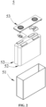
- Fig. 1 shows a space diagram of a secondary battery in a specific embodiment of the present application
- Fig. 2 is an exploded view of the secondary battery shown in Fig. 1
- the secondary battery 5 (hereinafter referred to as battery cell 5) according to the present application comprises an outer package 51, an electrode assembly 52, a top cover assembly 53, and an electrolyte solution (not shown).
- the electrode assembly 52 is accommodated within the case 51.
- the number of electrode assemblies 52 is not defined, and may be one or more.
- the battery cell 5 shown in Fig. 1 is a tank-type battery, but is not limited to the tank-type battery in the present application.
- the battery cell 5 may be a bag-type battery, i.e., the case 51 is replaced with a metal plastic film, and the top cover assembly 53 is canceled.
- the third aspect of the present application provides a battery module, comprising the secondary battery in the second aspect of the present application.
- the secondary batteries may be assembled into a battery module, the number of secondary batteries comprised in the battery module may be a plural number, and the specific number may be adjusted based on the application and capacity of the battery module.
- Fig. 3 is a space diagram of a battery module 4 as an example. Referring to Fig. 3 , in the battery module 4, a plurality of secondary batteries 5 may be sequentially arranged along a length direction of the battery module 4, and of course, may also be arranged in any other manner. The plurality of secondary batteries 5 may further be fixed by fasteners.
- the battery module 4 may further include a case having an accommodating space, in which the plurality of secondary batteries 5 is accommodated.
- the fourth aspect of the present application provides a battery pack, comprising the battery module in the third aspect of the present application.
- the battery modules may be assembled into a battery pack, and the number of battery modules comprised in the battery pack may be adjusted based on the application and capacity of the battery pack.
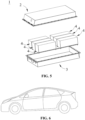
- Fig. 4 is a space diagram of a battery pack 1 as an example
- Fig. 5 is an exploded view of the battery pack shown in Fig. 4 .
- the battery pack 1 may comprise a battery box and a plurality of battery modules 4 arranged in the battery box.
- the battery box comprises an upper box 2 and a lower box 3.
- the upper box 2 can cover the lower box 3 and form an enclosed space for accommodating the battery module 4.
- the plurality of battery modules 4 may be arranged in the battery box in any manner.
- the fifth aspect of the present application provides an electrical apparatus, comprising the secondary battery in the second aspect of the present application, or the battery module in the third aspect of the present application, or the battery pack in the fourth aspect of the present application.
- the secondary battery, or the battery module, or the battery pack may be used as a power source of the electrical apparatus, or an energy storage unit of the electrical apparatus.
- the electrical apparatus may be, but is not limited to, a mobile device (such as a mobile phone or a laptop), an electric vehicle (such as an all-electric vehicle, a hybrid electric vehicle, a plug-in hybrid electric vehicle, an electric bicycle, an electric scooter, an electric golf cart, an electric truck), an electric train, a ship, a satellite, an energy storage system, etc.
- the secondary battery, the battery module, or the battery pack may be selected for the electrical apparatus based on use demand thereof.
- Fig. 6 shows a schematic diagram of an electrical apparatus in a specific embodiment of the present application.
- the electrical apparatus may be, e.g., an all-electric vehicle, a hybrid electric vehicle, or a plug-in hybrid electric vehicle.
- a battery pack or a battery module may be used.
- the electrical apparatus may be a mobile phone, a tablet, a laptop, etc.
- the electrical apparatus is generally required to be light and thin, and can use a secondary battery of the present application as a power source.
- Test process is shown in Table 1 (where C is rated capacity of the battery cell).
- Table 1 Step No. Test process Temperature (°C) Notes step 1, normal temperature capacity process 1) Rest 5 min 25 2) 1/3C DC 2.8V 25 3) Rest 15 min 25 4) 1/3C CC 4.2V CV 0.05C 25 5) Rest 15 min 25 6) 1/3C DC 2.8V 25 (Energy E0) 7) Rest 15 min 25 Step 2, -10 °C capacity process 1) Rest 2 h 25 2) 1/3C CC 4.2V CV 0.05C 25 3) Rest 2 h -10 4) 1/3C DC 2.8V -10 (Energy E1)
- the active material layer of the positive electrode sheet in Examples 1-15 has the characteristics of the bilayered three-level pore size distribution provided in the present invention. Under the premise that mass and energy density of the positive electrode active material are not reduced, such a bilayered three-level pore size distribution not only guarantees lithium-ion transport capacity of micropores in the active material layer, but also achieves consistent lithium-ion transport capacity in the inner active material layer and the outer active material layer.
- the pore size distribution in the inner active material layer and the outer active material layer is reasonable, thereby avoiding space occupying effects and filling effects, further avoiding or reducing sharp decline of internal lithium-ion transport capacity of the secondary battery in a low-temperature environment, and significantly improving low-temperature charge-discharge performance of the secondary battery. Therefore, the low-temperature energy retention rate of the secondary battery and the maximum output power of the secondary battery at a low temperature in a low SOC in Examples 1-15 in Table 3 are obviously better than those in Comparative Examples 1-5.
- Comparative Example 1 the active material layer on the surface of the positive electrode sheet is monolayer coated, and the monolayer coated active material layer has no characteristics of the three-level pore size distribution.
- both internal kinetic performance and external kinetic performance of the electrode sheet are poor, and the low-temperature charge-discharge performance of the secondary battery is obviously worse than that in Examples 1-15.
- Comparative Example 2 the primary pore size of the inner active material layer and the outer active material layer is too large, which is conductive to transport of the electrolyte solution, but the specific surface area of the active material layer is significantly reduced, and its electrochemical active point location is also significantly reduced.
- Comparative Example 3 the secondary pore size and the tertiary pore size of the inner active material layer and the outer active material layer are too large, i.e., the particle size of the active material particle is also large, and the kinetic performance of the large active material particle is poor, which is more obvious at a low temperature.
- Comparative Example 4 the primary pore size of the inner active material layer and the outer active material layer is too large, and the secondary pore size and the tertiary pore size of the inner active material layer and the outer active material layer are too large, so that the battery has the defects of both Comparative Example 2 and Comparative Example 3.
- the active material layer on the surface of the positive electrode sheet is also bilayer coated and has a three-level pore size distribution, but the pore size distribution is not reasonable, thereby failing to effectively contribute to lithium-ion transport, and failing to avoid sharp decline of internal lithium-ion transport capacity of the secondary battery in a low-temperature environment. Therefore, in Comparative Examples 2-4, the low-temperature charge-discharge performance of the secondary battery is not improved, as shown by poor low-temperature energy retention rate and poor maximum output power at a low temperature in a low SOC.
- the active material layer on the surface of the positive electrode sheet is also bilayer coated and has a three-level pore size distribution, but a particle size distribution solution of the active material particle with better kinetic performance is used as the outer active material layer, while a particle size distribution solution of the active material particle with poor kinetic performance is used as the inner active material layer, thereby failing to effectively contribute to lithium-ion transport.
- the low-temperature energy retention rate of the secondary battery and the maximum output power of the secondary battery at a low temperature in a low SOC are even worse than those in Comparative Examples 1-4.
- Examples 11 and 12 show the effects of the mass ratio of the first active material to the second active material in the inner active material layer and the outer active material layer on the technical effects of the present invention.
- a mass ratio of an active material forming the secondary pore size (i.e., the first active material) to an active material forming the tertiary pore size (i.e., the second active material) is too large, the active material layer has a small compaction density, thereby resulting in decline of an energy density of the secondary battery.
- the mass ratio of the active material forming the secondary pore size (i.e., the first active material) to the active material forming the tertiary pore size (i.e., the second active material) is small, an internal lithium-ion transmission path in the active material with a large particle size is too long, thus having adverse effects on kinetic performance of the secondary battery.
- Examples 13-15 show the effects of the mass ratio of the conductive agent to the active material in the inner active material layer and the outer active material layer on the technical effects of the present invention. If the mass ratio of the conductive agent to the active material is too small, the conductivity becomes poor, which is not conducive to the kinetic performance. Otherwise, if the mass ratio of the conductive agent to the active material is too large, although increase of the conductive agent can increase the conductivity between the active materials, thereby improving an energy retention rate of the secondary battery to a certain extent, but failing to be conductive to improvement of the energy density of the secondary battery.
Landscapes
- Chemical & Material Sciences (AREA)
- Chemical Kinetics & Catalysis (AREA)
- Electrochemistry (AREA)
- General Chemical & Material Sciences (AREA)
- Engineering & Computer Science (AREA)
- Materials Engineering (AREA)
- Composite Materials (AREA)
- Manufacturing & Machinery (AREA)
- Inorganic Chemistry (AREA)
- Battery Electrode And Active Subsutance (AREA)
- Secondary Cells (AREA)
Abstract
Description
- The present application claims the priority of
Chinese Patent Application No. 202111159354.7 filed on 30 September 2021 - The present application relates to the field of batteries, and specifically relates to a positive electrode sheet, a secondary battery, a battery module, a battery pack, and an electrical apparatus.
- With the rapid development of the application of secondary batteries in electric vehicles and military field, a defect that low-temperature performance thereof fails to adapt to special low-temperature weather or extreme environments has attracted increasingly more attention. Under low-temperature conditions, both effective discharge capacity and effective discharge amount of a secondary battery will be obviously reduced, and its charge performance is extremely poor in an environment at below -10 °C, thereby seriously restricting application of the secondary battery.
- The secondary battery is mainly composed by a positive electrode sheet, a negative electrode sheet, a separator, and an electrolyte solution. The secondary battery in a low-temperature environment has characteristics of low discharge voltage platform, low discharge capacity, quick capacity attenuation, poor rate performance, and the like. Low-temperature performance restricts the application of the secondary batteries in the field of electric vehicles, military field, and extreme environments. Therefore, development of a secondary battery with outstanding low-temperature performance is an urgent market demand.
- In view of the problems existing in the Background Art, the present application provides a positive electrode sheet, a secondary battery, a battery module, a battery pack, and an electrical apparatus.
- In a first aspect, the present application provides a positive electrode sheet, comprising a positive electrode current collector and a positive electrode active material layer coated on at least one surface of the positive electrode current collector. The positive electrode active material layer successively comprises an inner active material layer stacked on a surface of the positive electrode current collector and an outer active material layer stacked on a surface of the inner active material layer.
- The inner active material layer has a three-level pore size distribution: an inner primary pore size distribution from 3 nm to 10 nm, and optionally from 6 nm to 10 nm; an inner secondary pore size distribution from 10 nm to 100 nm, and optionally from 10 nm to 84 nm; and an inner tertiary pore size distribution from 0.1 µm to 2 µm, and optionally from 0.1 µm to 1.26 µm.
- The outer active material layer has a three-level pore size distribution: an outer primary pore size distribution from 0.5 nm to 3 nm, and optionally from 1 nm to 3 nm; an outer secondary pore size distribution from 10 nm to 100 nm, and optionally from 60 nm to 100 nm; and an outer tertiary pore size distribution from 0.1 µm to 2 µm, and optionally from 0.45 µm to 2 µm.
- Compared with the prior art, the active material layer of the positive electrode sheet provided in the present application has characteristics of a bilayered three-level pore size distribution. Under the premise that mass and energy density of the positive electrode active material are not reduced, such a bilayered three-level pore size distribution not only guarantees lithium-ion transport capacity of micropores in the active material layer, but also achieves consistent lithium-ion transport capacity in the inner active material layer and the outer active material layer. At the same time, the pore size distribution in the inner active material layer and the outer active material layer is reasonable, thereby avoiding space occupying effects and filling effects, further avoiding or reducing sharp decline of internal lithium-ion transport capacity of the secondary battery in a low-temperature environment, and significantly improving low-temperature charge-discharge performance of the secondary battery.
- In some optional embodiments, the inner active material layer comprises an inner conductive agent and an inner active material, and the outer active material layer comprises an outer conductive agent and an outer active material.
- The primary pore size distribution in the inner active material layer and the outer active material layer can be formed by selecting a conductive agent particle with an appropriate specific surface area.
- A specific surface area of the inner conductive agent is from 300 m2/g to 1,000 m2/g, and optionally, the specific surface area of the inner conductive agent is from 800 m2/g to 1,000 m2/g.
- A specific surface area of the outer conductive agent is from 1,000 m2/g to 2,500 m2/g, and optionally, the specific surface area of the outer conductive agent is from 2,000 m2/g to 2,500 m2/g.
- In some optional embodiments, the secondary pore size distribution and the tertiary pore size distribution in the inner active material layer and the outer active material layer can be formed by selecting a mixture of active material particles with bimodal particle size.
- In some optional embodiments, a particle size distribution of the inner first active material is from 24 nm to 600 nm, and optionally, the particle size distribution of the inner first active material is from 24 nm to 200 nm; and a particle size distribution of the inner second active material is from 0.25 µm to 13 µm, and optionally, the particle size distribution of the inner second active material is from 0.5 µm to 3 µm.
- A particle size distribution of the outer first active material is from 24 nm to 600 nm, and optionally, the particle size distribution of the outer first active material is from 200 nm to 400 nm; and a particle size distribution of the outer second active material is from 0.25 µm to 13 µm, and optionally, the particle size distribution of the outer second active material is from 3 µm to 8 µm.
- In some optional embodiments, a particle size of the inner first active material does not overlap with the inner tertiary pore size; and/or a particle size of the outer first active material does not overlap with the outer tertiary pore size. That is, a particle size of an active material forming the secondary pore size in the inner layer and the outer layer is not equal to the tertiary pore size, thereby avoiding space occupying effects of first active material particles.
- In some optional embodiments, a mass ratio of the inner first active material to the inner second active material is (0.3-3): 1. Optionally, the mass ratio of the inner first active material to the inner second active material is (1-3): 1.
- In some optional embodiments, a mass ratio of the outer first active material to the outer second active material is (0.3-3): 1. Optionally, the mass ratio of the outer first active material to the outer second active material is (0.3-1): 1.
- In the inner active material layer and the outer active material layer, when a mass of the first active material and a mass of the second active material are within the above range, a lamination density of the active material layer and an internal lithium-ion transmission path in the active material are at a favorable level, thereby guaranteeing energy density and kinetic performance of the secondary battery in the low-temperature environment.
- In some optional embodiments, a mass ratio of the inner conductive agent to the inner active material is (0.3-2): 100. Optionally, the mass ratio of the inner conductive agent to the inner active material is (1.5-2): 100.
- Optionally, a mass ratio of the outer conductive agent to the outer active material is (0.3-3): 100. Optionally, the mass ratio of the outer conductive agent to the outer active material is (2.5-3):100.
- The mass ratio of the conductive agent to the active material in the inner active material layer and the outer active material layer is kept within an appropriate range, such that conductivity and kinetic performance of the electrode sheet and energy density of the secondary battery can be kept within a favorable range.
- In some optional embodiments, the inner conductive agent and the outer conductive agent are each independently selected from activated carbon or carbon nanotube. The activated carbon or carbon nanotube not only has favorable conductivity, but also has a large specific surface area, and can favorably form the primary pore size distribution in the inner active material layer and the outer active material layer.
- In a second aspect, the present application provides a secondary battery, comprising a positive electrode sheet, a negative electrode sheet, a separator between the positive electrode sheet and the negative electrode sheet, and an electrolyte solution, where the positive electrode sheet is the positive electrode sheet in the first aspect of the present application.
- In a third aspect, the present application provides a battery module, comprising the secondary battery in the second aspect of the present application.
- In a fourth aspect, the present application provides a battery pack, comprising the secondary battery in the second aspect of the present application or the battery module in the third aspect of the present application.
- In a fifth aspect, the present application provides an electrical apparatus, comprising the secondary battery in the second aspect of the present application, or the battery module in the third aspect of the present application, or the battery pack in the fourth aspect of the present application; where the secondary battery or the battery module or the battery pack is used as a power source or an energy storage unit of the electrical apparatus.
- The secondary battery, the battery module, the battery pack, and the electrical apparatus provided in the present application comprise the positive electrode sheet in the first aspect of the present application, and thus have at least identical or similar technical effects to the above positive electrode sheet.
-
-
Fig. 1 is a space diagram of a secondary battery in a specific embodiment of the present application; -
Fig. 2 is an exploded view of the secondary battery shown inFig. 1 ; -
Fig. 3 is a space diagram of a battery module in a specific embodiment of the present application; -
Fig. 4 is a space diagram of a battery pack in a specific embodiment of the present application; -
Fig. 5 is an exploded view of the battery pack shown inFig. 4 ; and -
Fig. 6 is a schematic diagram of an electrical apparatus in a specific embodiment of the present application. -
- 1. Battery pack;
- 2. Upper box;
- 3. Lower box;
- 4. Battery module;
- 5. Secondary battery;
- 51. Case;
- 52. Electrode assembly; and
- 53. Top cover assembly.
- Embodiments of the technical solutions of the present application will be described in detail below with reference to the drawings. The following embodiments are merely used to more clearly describe the technical solutions of the present application, are therefore only used as examples, and cannot be used to limit the scope of protection of the present application. Unless otherwise defined, all technical terms and scientific terms used herein have the same meaning as commonly understood by those skilled in the technical field of the present application.
- Reference herein to an "embodiment" means that a particular feature, structure, or characteristic described with reference to the embodiment may be included in at least one embodiment of the present application. The appearances of the phrase in various places in the specification neither necessarily refer to the same embodiment, nor are independent or alternative embodiments mutually exclusive with other embodiments. It is explicitly and implicitly understood by those skilled in the art that the embodiments described herein may be combined with other embodiments.
- The first aspect of the present application provides a positive electrode sheet, comprising a positive electrode current collector and a positive electrode active material layer arranged on at least one surface of the positive electrode current collector. The positive electrode active material layer successively comprises an inner active material layer stacked on a surface of the positive electrode current collector and an outer active material layer stacked on a surface of the inner active material layer.
- The inner active material layer has a three-level pore size distribution: an inner primary pore size distribution from 3 nm to 10 nm, and optionally from 6 nm to 10 nm; an inner secondary pore size distribution from 10 nm to 100 nm, and optionally from 10 nm to 84 nm; and an inner tertiary pore size distribution from 0.1 µm to 2 µm, and optionally from 0.1 µm to 1.26 µm.
- The outer active material layer has a three-level pore size distribution: an outer primary pore size distribution from 0.5 nm to 3 nm, and optionally from 1 nm to 3 nm; an outer secondary pore size distribution from 10 nm to 100 nm, and optionally from 60 nm to 100 nm; and an outer tertiary pore size distribution from 0.1 µm to 2 µm, and optionally from 0.45 µm to 2 µm.
- The pore size distribution in the present application refers to an equivalent diameter distribution of pore channels in a porous solid, and can be determined by gas adsorption method and/or mercury porosimetry, for example, with reference to GB T 21650.1-2008 Pore size distribution and porosity of solid materials by mercury porosimetry and gas adsorption.
- The inventor holds that rapid increase of viscosity and sharp decline of internal lithium-ion transport capacity of a secondary battery at a low temperature are an important reason for its poor charge-discharge performance in a low-temperature environment. The inventor further presents that: on the one hand, when there is a micropore with a small pore size in the positive electrode active material layer, the micropore becomes a main factor affecting the lithium-ion transport capacity. When the pore size of the micropore is less than a size of 1 solvated lithium-ion (a diameter of the solvated lithium-ion is about 1 nm), the solvated lithium-ion fails to pass through the micropore, and the battery has extremely low lithium-ion transport capacity; when the pore size of the micropore is a size of 1-3 solvated lithium-ions, the battery has moderate lithium-ion transport capacity; and when the pore size of the micropore is a size of 4-10 solvated lithium-ions, the battery has optimum lithium-ion transport capacity. On the other hand, there is a wide particle size distribution of the active material on a surface of the positive electrode sheet, indicating that the active material has different particle sizes and a high irregularity degree. In this case, large particles occupy larger positions, thereby reducing pore gaps formed by accumulation of particles, and forming space occupying effects. However, small particles will fill in pore gaps formed by accumulation of other particles, thereby forming filling effects. Neither the space occupying effects nor the filling effects contribute to lithium-ion transport.
- On this basis, the technical solutions provided in the present application include: forming a bilayer coated active material layer on the surface of the positive electrode current collector: forming a three-level pore size distribution in an inner layer: 3 nm-10 nm (optionally 6 nm-10 nm), 10 nm-100 nm (optionally 10 nm-84 nm), and 0.1 µm-2 µm (optionally 0.1 µm-1.26 µm); and forming a three-level pore size distribution in an outer layer: 0.5 nm-3 nm (optionally 1 nm-3 nm), 10 nm-100 nm (optionally 60 nm-100 nm), and 0.1 µm-2 µm (optionally 0.45 µm-2 µm). Under the premise that mass and energy density of the positive electrode active material are not reduced, such a bilayered three-level pore size distribution not only guarantees lithium-ion transport capacity of micropores in the active material layer, but also achieves consistent lithium-ion transport capacity in the inner active material layer and the outer active material layer. At the same time, the pore size distribution in the inner active material layer and the outer active material layer is reasonable, thereby avoiding space occupying effects and filling effects, improving conductivity of the electrode sheet in this case, avoiding or reducing sharp decline of internal lithium-ion transport capacity of the secondary battery at a low temperature, and significantly improving low-temperature charge-discharge performance of the secondary battery.
- Further, in an embodiment of the present application, the inner active material layer may comprise an inner conductive agent and an inner active material, and the outer active material layer may comprise an outer conductive agent and an outer active material.
- In an embodiment of the present application, the primary pore size distribution in the inner layer and the outer layer can be formed by selecting a conductive agent particle with a specific surface area in a specific range. In some embodiments, a specific surface area of the inner conductive agent may be from 300 m2/g to 1,000 m2/g (optionally from 800 m2/g to 1,000 m2/g). In some embodiments, a specific surface area of the outer conductive agent may be from 1,000 m2/g to 2,500 m2/g (optionally from 2,000 m2/g to 2,500 m2/g).
- A specific surface area of the active material particle in the present application can be measured by gas adsorption method (BET) or mercury porosimetry. In the present application, the specific surface area has a well-known meaning in the art, and may be determined using known instruments and methods in the art, for example, may be tested using the specific surface area analysis and test method by nitrogen adsorption with reference to GB/T 19587-2017, and computed using the BET (BrunauerEmmett Teller) method, where the specific surface area analysis and test by nitrogen adsorption may be carried out using Tri-Star 3020 surface area and porosity analyzer of Micrometrics Instruments Corporation.
- In an embodiment of the present application, a secondary pore size and a tertiary pore size in the inner layer and the outer layer can be formed by selecting an active material particle with bimodal particle size.
- In some embodiments, a particle size distribution of the inner first active material may be from 24 nm to 600 nm, and optionally, the particle size distribution of the inner first active material may be from 24 nm to 200 nm. In some embodiments, a particle size distribution of the inner second active material may be from 0.25 µm to 13 µm, and optionally, the particle size distribution of the inner second active material may be from 0.5 µm to 3 µm.
- In some embodiments, a particle size distribution of the outer first active material may be from 24 nm to 600 nm, and optionally, the particle size distribution of the outer first active material may be from 200 nm to 400 nm. In some embodiments, a particle size distribution of the outer second active material may be from 0.25 µm to 13 µm, and optionally, the particle size distribution of the outer second active material may be from 3 µm to 8 µm.
- Further optionally, a particle size of the inner first active material may not overlap with the inner tertiary pore size; and a particle size of the outer first active material may not overlap with the outer tertiary pore size. That is, a particle size of an active material forming the secondary pore size in the inner layer and the outer layer is not equal to the tertiary pore size, thereby avoiding space occupying effects of first active material particles.
- The particle size in the present application refers to an equivalent diameter of the active material particle, and means that when a to-be-tested active material particle is closest to a homogeneous sphere (or a combination of spheres) of a certain diameter, the diameter of the sphere (or the combination of spheres) is taken as a particle size distribution of the to-be-tested particle. In the present application, the particle size distribution of the active material particle can be detected using a laser particle size analyzer.
- In some embodiments, a mass ratio of the inner first active material to the inner second active material may be (0.3-3):1. Optionally, the mass ratio of the inner first active material to the inner second active material may be (1-3): 1.
- In some embodiments, a mass ratio of the outer first active material to the outer second active material may be (0.3-3):1. Optionally, the mass ratio of the outer first active material to the outer second active material may be (0.3-1): 1.
- In the inner active material layer and the outer active material layer, when a mass ratio of the active material forming the secondary pore size (i.e., the first active material) to an active material forming the tertiary pore size (i.e., the second active material) is too large, the active material layer has a small compaction density, thereby resulting in decline of an energy density of the secondary battery. Otherwise, when the mass ratio of the active material forming the secondary pore size (i.e., the first active material) to the active material forming the tertiary pore size (i.e., the second active material) is too small, an internal lithium-ion transmission path in the active material with a large particle size is too long, thus having adverse effects on kinetic performance of the secondary battery.
- In some embodiments, a mass ratio of the inner conductive agent to the inner active material may be (0.3-2): 100. Optionally, the mass ratio of the inner conductive agent to the inner active material may be (1.5-2): 100.
- In some embodiments, a mass ratio of the outer conductive agent to the outer active material may be (0.3-3): 100; and optionally, the mass ratio of the outer conductive agent to the outer active material may be (2.5-3): 100.
- In the inner active material layer and the outer active material layer, if the mass ratio of the conductive agent to the active material is too small, the conductivity becomes poor, which is not conducive to the kinetic performance. Otherwise, if the mass ratio of the conductive agent to the active material is too large, although increase of the conductive agent can increase the conductivity between the active materials, thereby improving an energy retention rate of the secondary battery to a certain extent, but failing to be conductive to improvement of the energy density of the secondary battery. In addition, a use amount of the conductive agent in each layer is also associated with a specific surface area of the active material and a particle size of the conductive agent in the layer. The larger the specific surface area of the active material is and the larger the particle size of the conductive agent is, the larger the use amount of the conductive agent is required. In the present application, the particle size of the inner active material is optionally larger than the particle size of the outer active material. Therefore, the use amount of the conductive agent in the inner layer is also optionally slightly smaller than the use amount of the conductive agent in the outer layer.
- In some embodiments, the inner conductive agent and the outer conductive agent may each independently be selected from activated carbon or carbon nanotube. The activated carbon or carbon nanotube not only has favorable conductivity, but also has a large specific surface area, and can favorably form the primary pore size distribution in the inner active material layer and the outer active material layer.
- In addition, in some embodiments of the present application, the specific type of the positive electrode active material is not particularly limited, as long as the positive electrode active material can satisfy intercalation and deintercalation of lithium-ions. The positive electrode active material either may be a material with a layered structure, such that the lithium-ions diffuse in a two-dimensional space, or may be a material with a spinel structure, such that the lithium-ions diffuse in a three-dimensional space. Optionally, the positive electrode active material may be selected from one or more of a lithium transition metal oxide or a compound obtained from doping a lithium transition metal oxide with other transition metals or non-transition metals or non-metals. Specifically, the positive electrode active material may be selected from one or more of a lithium-cobalt oxide, a lithium-nickel oxide, a lithium-manganese oxide, a lithium-nickel-manganese oxide, a lithium-nickel-cobalt-manganese oxide, a lithium-nickel-cobalt-aluminum oxide, or a lithium-containing phosphate of olivine structure.
- A general formula of the lithium-containing phosphate of olivine structure may be LiFe1-x-yMnxM'yPO4, where 0≤x≤1, 0≤y<1, 0≤x+y≤1, M' may be selected from one or more of other transition metal elements or non-transition metal elements except for Fe and Mn, and M' may be selected from one or more of Cr, Mg, Ti, Al, Zn, W, Nb, or Zr. More optionally, the lithium-containing phosphate of olivine structure may be selected from one or more of lithium iron phosphate, lithium manganese phosphate, or lithium manganese iron phosphate.
- The lithium transition metal oxide may be selected from one or more of LiCoO2, LiMnO2, LiNiO2, LiMn2O4, LiNixCoyMn1-x-yO2, LiNixCoyAl1-x-yO2, or LiNixMn2-xO4, where 0<x<1, 0<y<1, and 0<x+y<1. Optionally, the lithium transition metal oxide may be selected from one or more of LiCoO2, LiNi1/3Co1/3Mn1/3O2, LiNi0.5Co0.2Mn0.3O2, LiNi0.6Co0.2Mn0.2O2, LiNi0.8Co0.1Mn0.1O2, LiNi0.8Co0.15Mn0.05O2, LiNi0.8Co0.15Al0.05O2, LiNi0.5Mn1.5O4, or LiMn2O4.
- In some embodiments of the present application, the positive electrode active material layer may further comprise a binder, where the type and content of the binder are not specifically limited, either, and may be selected according to actual requirements, The binder generally may include a fluorine-containing polyolefin binder. Compared with the fluorine-containing polyolefin binder, water is generally a good solvent, i.e., the fluorine-containing polyolefin binder generally has good solubility in water. For example, the fluorine-containing polyolefin binder may include, is but not limited to, polyvinylidene fluoride (PVDF), vinylidene fluoride copolymer, or a modified derivative (such as carboxylic acid, acrylic acid, and acrylonitrile) thereof. In the positive electrode material layer, a percentage mass content of the binder may be such that a use amount of the binder cannot be too high due to the poor conductivity of the binder itself.
- In some embodiments of the present application, the type of the positive electrode current collector is not specifically limited, either, and may be selected according to actual requirements. The positive electrode current controller generally may be a layered body, and the positive electrode current controller is generally a structure or part capable of collecting current. The positive electrode current collector may be various materials suitable for use as positive electrode current collectors of electrochemical energy storage apparatuses in the art. For example, the positive electrode current collector may include, but is not limited to, a metal foil, and more specifically, may include, but is not limited to, a nickel foil and an aluminum foil.
- In the second aspect, the present application provides a secondary battery, comprising a positive electrode sheet, a negative electrode sheet, a separator between the positive electrode sheet and the negative electrode sheet, and an electrolyte solution, where the positive electrode sheet is the positive electrode sheet in the first aspect of the present application.
- In some embodiments, the negative electrode sheet of the secondary battery generally comprises a negative electrode current collector and a negative electrode active material layer arranged on a surface of the negative electrode current collector, and the negative electrode active material layer generally comprises a negative electrode active material. The negative electrode active material may be various materials suitable for negative electrode active materials of lithium secondary batteries in the art, for example, may include, but is not limited to, a combination of one or more of graphite, soft carbon, hard carbon, carbon fiber, mesocarbon microbead, silicon-based material, tin-based material, lithium titanate, or other metals that can be alloyed with lithium. The graphite may be selected from a combination of one or more of artificial graphite, natural graphite, and modified graphite; the silicon-based material may be selected from a combination of one or more of elementary silicon, silicon-oxygen compound, silicon-carbon composite, and silicon alloy; and the tin-based material may be selected from a combination of one or more of elementary tin, tin-oxygen compound, and tin alloy. The negative electrode current collector is generally a structure or part collecting current. The negative electrode current collector may be various materials suitable for use as negative electrode current collectors of lithium secondary batteries in the art. For example, the negative electrode current collector may include, but is not limited to, a metal foil, and more specifically, may include, but is not limited to, a copper foil. In addition, the negative electrode sheet may also be a lithium sheet.
- In some embodiments, the electrolyte solution of the secondary battery may be various electrolyte solutions suitable for secondary batteries in the art. For example, the electrolyte solution generally comprises an electrolyte and a solvent; the electrolyte generally may include a lithium salt; and more specifically, the lithium salt may be an inorganic lithium salt and/or an organic lithium salt, and specifically may include, but is not limited to, a combination of one or more of LiPF6, LiBF4, LiN(SO2F)2 (abbreviated as LiFSI), LiN(CF3SO2)2 (abbreviated as LiTFSI), LiClO4, LiAsF6, LiB(C2O4)2 (abbreviated as LiBOB), and LiBF2C2O4 (abbreviated as LiDFOB). For another example, a concentration of the electrolyte may be from 0.8 mol/L to 1.5 mol/L. The solvent may be various solvents suitable for electrolyte solutions of secondary batteries in the art. The solvent of the electrolyte solution is generally a non-aqueous solvent, may be an organic solvent, and specifically may include, but is not limited to, a combination of one or more of ethylene carbonate, propylene carbonate, butylene carbonate, pentylene carbonate, dimethyl carbonate, diethyl carbonate, dipropyl carbonate, ethyl methyl carbonate, or a halogenated derivative thereof.
- In some embodiments, the separator of the secondary battery may be various materials suitable for separators of secondary batteries in the art, for example, may include, but is not limited to, a combination of one or more of polyethylene, polypropylene, polyvinylidene fluoride, aramid, polyethylene terephthalate, polytetrafluoroethylene, polyacrylonitrile, polyimide, polyamide, polyester, and natural fiber.
- In some embodiments, the method for preparing a secondary battery should be known to those skilled in the art. For example, the positive electrode sheet, the separator, and the negative electrode sheet may each be a layered body, such that they may be cut to a target size and then sequentially stacked, or may be winded to the target size to form a battery cell, and may be further combined with the electrolyte solution to form the secondary battery.
-
Fig. 1 shows a space diagram of a secondary battery in a specific embodiment of the present application, andFig. 2 is an exploded view of the secondary battery shown inFig. 1 . Referring toFig. 1 andFig. 2 , the secondary battery 5 (hereinafter referred to as battery cell 5) according to the present application comprises anouter package 51, anelectrode assembly 52, atop cover assembly 53, and an electrolyte solution (not shown). Theelectrode assembly 52 is accommodated within thecase 51. The number ofelectrode assemblies 52 is not defined, and may be one or more. - It should be noted that the
battery cell 5 shown inFig. 1 is a tank-type battery, but is not limited to the tank-type battery in the present application. Thebattery cell 5 may be a bag-type battery, i.e., thecase 51 is replaced with a metal plastic film, and thetop cover assembly 53 is canceled. - The third aspect of the present application provides a battery module, comprising the secondary battery in the second aspect of the present application. In some embodiments, the secondary batteries may be assembled into a battery module, the number of secondary batteries comprised in the battery module may be a plural number, and the specific number may be adjusted based on the application and capacity of the battery module.
Fig. 3 is a space diagram of abattery module 4 as an example. Referring toFig. 3 , in thebattery module 4, a plurality ofsecondary batteries 5 may be sequentially arranged along a length direction of thebattery module 4, and of course, may also be arranged in any other manner. The plurality ofsecondary batteries 5 may further be fixed by fasteners. Optionally, thebattery module 4 may further include a case having an accommodating space, in which the plurality ofsecondary batteries 5 is accommodated. - The fourth aspect of the present application provides a battery pack, comprising the battery module in the third aspect of the present application. In some embodiments, the battery modules may be assembled into a battery pack, and the number of battery modules comprised in the battery pack may be adjusted based on the application and capacity of the battery pack.
Fig. 4 is a space diagram of abattery pack 1 as an example, andFig. 5 is an exploded view of the battery pack shown inFig. 4 . Referring toFig. 4 andFig. 5 , thebattery pack 1 may comprise a battery box and a plurality ofbattery modules 4 arranged in the battery box. The battery box comprises anupper box 2 and alower box 3. Theupper box 2 can cover thelower box 3 and form an enclosed space for accommodating thebattery module 4. The plurality ofbattery modules 4 may be arranged in the battery box in any manner. - The fifth aspect of the present application provides an electrical apparatus, comprising the secondary battery in the second aspect of the present application, or the battery module in the third aspect of the present application, or the battery pack in the fourth aspect of the present application. The secondary battery, or the battery module, or the battery pack may be used as a power source of the electrical apparatus, or an energy storage unit of the electrical apparatus. The electrical apparatus may be, but is not limited to, a mobile device (such as a mobile phone or a laptop), an electric vehicle (such as an all-electric vehicle, a hybrid electric vehicle, a plug-in hybrid electric vehicle, an electric bicycle, an electric scooter, an electric golf cart, an electric truck), an electric train, a ship, a satellite, an energy storage system, etc.
- The secondary battery, the battery module, or the battery pack may be selected for the electrical apparatus based on use demand thereof.
-
Fig. 6 shows a schematic diagram of an electrical apparatus in a specific embodiment of the present application. The electrical apparatus may be, e.g., an all-electric vehicle, a hybrid electric vehicle, or a plug-in hybrid electric vehicle. In order to meet the requirements of the electrical apparatus for high power and high energy density of secondary batteries, a battery pack or a battery module may be used. - As another example, the electrical apparatus may be a mobile phone, a tablet, a laptop, etc. The electrical apparatus is generally required to be light and thin, and can use a secondary battery of the present application as a power source.
- Those skilled in the art can understand that: in different examples of the present application, various definitions or optional ranges of component selection, component content, and physical and chemical performance parameters of the electrochemical active material can be combined in any manner, and various examples obtained from combinations thereof are still encompassed within the scope of the present application, and are considered as a part of contents disclosed in the present specification.
- Advantages of the present application will be further described below with reference to specific examples. It should be understood that these examples are provided merely to illustrate the present application, rather than limiting the scope of the present application.
-
- 1. Preparation of the positive electrode sheet:
- (1) Coating of an inner layer: an inner first active material and an inner second active material were proportionally mixed. The resulting mixture, a binder (1.8%), a dispersant (0.2%), and an appropriate amount of NMP were fully stirred and mixed, to form a homogeneous slurry for the inner layer. The slurry for the inner layer was coated on the positive electrode current collector (an Al foil), and dried; and
- (2) Coating of an outer layer: an outer first active material and an outer second active material were proportionally mixed. The resulting mixture, a binder (1.6%), a dispersant (0.2%), and an appropriate amount of NMP were fully stirred and mixed, to form a homogeneous slurry for the outer layer. The slurry was coated on the electrode sheet coated with the slurry for the inner layer, and dried. Then, the positive electrode sheet was cold pressed to a designed compaction density, and striped for later use.
- 2. A negative electrode sheet, a separator, an electrolyte solution, and a case were obtained according to conventional methods in the art:
- Negative electrode sheet: A negative electrode active material (graphite), conductive carbon, and a binder (polyvinylidene fluoride (PVDF)) at a weight ratio of 95:3:2 were fully stirred mixed in an appropriate amount of an aqueous solvent, to form a homogeneous negative electrode slurry; The slurry was coated on a negative current collector (a Cu foil), and dried. Then, the electrode sheet was cold pressed to a designed compaction density, and striped for later use.
- Separator: A PP separator of 12 µm was used.
- Electrolyte solution: A universal electrolyte solution (lithium iron phosphate) was used.
- Case: An aluminum plastic film was used as a case material.
- 3. Preparation of the secondary battery:
The positive electrode sheet, the separator, and the negative electrode sheet were winded to form a bare battery cell. The bare battery cell was encapsulated with the aluminum plastic film, into which the electrolyte solution was injected. The lithium secondary battery was obtained through formation, venting, and high-temperature aging. - The following performance test was performed on the secondary battery in Examples 1-5 and Comparative Examples 1-15:
- 1. Test of a cycling energy retention rate of the secondary battery
- The test process is shown in Table 1 (where C is rated capacity of the battery cell).
Table 1 Step No. Test process Temperature (°C) Notes step 1, normal temperature capacity process 1) Rest 5 min25 2) 1/3C DC 2.8V 25 3) Rest 15 min 25 4) 1/3C CC 4.2V CV 0.05C 25 5) Rest 15 min 25 6) 1/3C DC 2.8V 25 (Energy E0) 7) Rest 15 min 25 Step 2, -10 °C capacity process1) Rest 2 h 25 2) 1/3C CC 4.2V CV 0.05C 25 3) Rest 2 h -10 4) 1/3C DC 2.8V -10 (Energy E1) - According to the above test steps, the -10 °C energy retention rate was obtained: -10 °C energy retention rate=E1/E0.
- The test process is shown in Table 2 (where C is rated capacity of the battery cell). The battery cell with the rated capacity of 20 Ah was tested.
Table 2 Step No. Test process Temperature (°C) Notes step 1, capacity process 1) Rest 5 min25 2) 1/3C DC 2.8V 25 3) Rest 15 min 25 4) 1/3C CC 4.2V CV 0.05C 25 5) Rest 15 min 25 6) 1/3C DC 2.8V 25 (denoting actual capacity C0 in this step) 7) Rest 15 min 25 step 2, -10 °C 30% SO C 30s power te st process1) Rest 5 min25 2) 1/3C CC4.2V CV 0.05C 25 3) Rest 10 min 25 4) 1/3C DC 0.7C0Ah 25 (adjusted to 30% SOC) 5) PAUSE -20 °C -10 6) Rest 2 h -10 7) Px DP 30s -10 Denoting capacity Cx 8) Rest 10 min -10 9) 0.05C CC 1CxAh -10 10) Rest 10 min -10 11) repeating steps 7-10, until the voltage in step 7 was 2.1± 0.05 V -10 until the cycle voltage was 2.1±0.05 V, where Px was taken as its maximum output power (Pmax) - Preparation parameters and performance test data of the positive electrode sheet and the secondary battery in Examples 1-15 and Comparative Examples 1-5 are shown in Table 3.
Table 3 Composition of active material layer of positive electrode sheet Battery performance test Specific surface area of conductive agent (m2/g) Particle size of first active material (nm) Particle size of second active material (µm) Mass ratio of first active material to second active material Mass ratio of conductive agent to active material Primary pore size distribution Secondary pore size distribution Tertiary pore size distribution -10 °C energy retention rate ( % ) Maximum output power Pmax (w) Example 1 Inner active material layer 300 24~600 0.25-13 1 : 1 1.8 : 100 3nm~10nm 10nm~100nm 0.1µm∼2µm 8496 160 Outer active material layer 1000 24~600 0.25-13 1:1 1.8 : 100 0.5nm∼3nm 10nm~100nm 0.1µm∼2µm Example 2 Inner active matrial layer 800 24~600 0.25-13 1 : 1 1.8 : 100 6nm∼10nm 10nm~100nm 0.1µm∼2µm 88% 170 Outer active material layer 1000 24~600 0.25-13 1 : 1 1.8 : 100 0.5nm∼3nm 10nm~100nm 0.1µm∼2µm Example 3 Inner active material layer 300 24~200 0.5-3 1 : 1 1.8 : 100 3nm~10nm 10nm∼84nm 0.1µm∼1.26µm 88% 169 Outer active material layer 1500 24~600 0.25-13 1 : 1 1.8 : 100 0.5nm∼3nm 10nm~100nm 0.1µm∼2µm Example 4 Inner active material layer 800 24~200 0.5~3 1 : 1 1.8 : 100 6nm~10nm 10nm∼84nm 0.1µm∼1.26µm 89% 176 Outer active material layer 1000 24~600 0.25~13 1 : 1 1.8 : 100 0.5nm∼3nm 10nm~100nm 0.1µm∼2µm Example 5 Inner active material layer 300 24~600 0.25~13 1 : 1 1.8 : 100 3nm~10nm 10nm~100nm 0.1µm~2µm 84% 160 Outer active material layer 2000 24~600 0.25~13 1:1 1.8 : 100 1nm∼3nm 10nm~100nm 0.1µm~2µm Example 6 Inner active material layer 300 24~600 0.25~13 1 : 1 1.8 : 100 3nm~10nm 10nm~100nm 0.1µm∼2µm 86% 165 Outer active material layer 1000 200~400 3~8 1: 1 1.8 : 100 0.5nm~3nm 60nm~100nm 0.45µm∼2µm Example 7 Inner active material byer 300 24~600 0.25~13 1: 1 1.8 : 100 3nm~10nm 10nm~100nm 0.1µm∼2µm 86% 166 Outer active material layer 2000 200~400 3-8 1: 1 1.8 : 100 1nm∼3nm 60nm∼100nm 0.45µm∼2µm Example 8 Inner active material layer 800 24~600 0.25~13 1:1 1.8 : 100 6nm~10nm 10nm~100nm 0.1µm~2µm 90% 180 Outer active material layer 2000 24~600 0.25~13 1:1 1.8 : 100 1nm-3nm 10nm~100nm 0.1µm~2µm Example 9 Inner active material layer 300 24~200 0.5~3 1:1 1.8 : 100 3nm~10nm 10nm∼84nm 0.1µm∼1.26µm 88% 171 Outer active material layer 1000 200~400 3~8 1 : 1 1.8 : 100 0.5nm∼3nm 60nm~100nm 0.45µm∼2µm Example 10 Inner active material layer 800 24~200 0.5~3 1:1 1.8 : 100 6nm~10nm 10nm∼84nm 0.1µm∼1.26µm 92% 183 Outer active material layer 2000 200~400 3~8 1:1 1.8 : 100 1nm~3nm 60nm~100nm 0.45µm∼2µm Example 11 Inner active material layer 800 24~200 0.5-3 0.3 : 1 1.8 : 100 6nm~10nm 10nm~84nm 0.1µm∼1.26µm 87% 167 Outer active material layer 2000 200~400 3-8 0.3 : 1 1.8 : 100 1nm~3nm 60nm~100nm 0.45µm∼2µm Example 12 Inner active material layer 800 24~200 0.5-3 3 : 1 1.8 : 100 6nm~10nm 10nm~84nm 3.1µm∼1.26µm 93% 192 Outer active material layer 2000 200~400 3-8 3:1 1.8 : 100 1nm~3nm 60nm~100nm 0.45µm∼2µm Example 13 Inner active material byer 800 24~200 0.5-3 1 : 1 0.3 : 100 6nm~10nm 10nm∼84nm 0.1µm∼1.26µm 86% 165 Outer active material layer 2000 200~400 3-8 1 : 1 0.3 : 100 1nm∼3nm 60nm~100nm 0.45µm∼2µm Example 14 Inner active material layer 800 24~200 0.5-3 1 : 1 1.5 : 100 6nm~10nm 10nm∼84nm 0.1µm∼1.26µm 93% 193 Outer active material layer 2000 200~400 3-8 1:1 2.5 : 100 1nm∼3nm 60nm~100nm 0.45µm~2µm Example 15 Inner active material layer 800 24~200 0.5-3 1 : 1 2 : 100 6nm~10nm 10nm∼84nm 0.1µm∼1.26µm 95% 198 Outer active material layer 2000 200~400 3-8 1 : 1 3 : 100 1nm∼3nm 60nm~100nm 0.45µm∼2µm Comparative Example 1 Single active material byer 300 50~2000 / 1.8 : 100 0.3∼10um 67% 123 Comparative Example 2 Outer active material layer 200 24~600 0.25-13 1:1 1.8 : 100 10~50nm 10nm~100nm 0.1µm-2µm 72% 135 Outer active material layer 200 24~600 0.25-13 1 : 1 1.8 : 100 10~50nm 10nm~100nm 0.1µm∼2µm Comparative Example 3 Inner active material layer 800 600~1000 13-20 1 : 1 1.8 : 100 6nm~10nm 100nm~400nm 2µm∼4µm 76% 143 Outer active material layer 2000 600~1000 13-20 1 : 1 1.8 : 100 1nm-3nm 100nm~400nm 2µm∼4µm Comparative Example 4 Inner active material layer 200 600∼1000 13-20 1 : 1 1.8 : 100 10~50nm 100nm~400nm 2µm∼4µm 70% 130 Outer active material layer 200 600-1000 13-20 1 : 1 1.8 : 100 10~50nm 100nm-400nm 2µm∼4µm Comparative Example 5 Inner active material layer 2000 200~400 3-8 1:1 3 : 100 1nm~3nm 60nm~100nm 0.45µm∼2µm 60% 103 Outer active material layer 800 24∼200 0.5∼3 1 : 1 2 : 100 6nm∼10nm 10nm∼84nm 0.1µm∼1.26µm - As can be seen from the battery performance test data in Table 3, the active material layer of the positive electrode sheet in Examples 1-15 has the characteristics of the bilayered three-level pore size distribution provided in the present invention. Under the premise that mass and energy density of the positive electrode active material are not reduced, such a bilayered three-level pore size distribution not only guarantees lithium-ion transport capacity of micropores in the active material layer, but also achieves consistent lithium-ion transport capacity in the inner active material layer and the outer active material layer. At the same time, the pore size distribution in the inner active material layer and the outer active material layer is reasonable, thereby avoiding space occupying effects and filling effects, further avoiding or reducing sharp decline of internal lithium-ion transport capacity of the secondary battery in a low-temperature environment, and significantly improving low-temperature charge-discharge performance of the secondary battery. Therefore, the low-temperature energy retention rate of the secondary battery and the maximum output power of the secondary battery at a low temperature in a low SOC in Examples 1-15 in Table 3 are obviously better than those in Comparative Examples 1-5.
- In Comparative Example 1, the active material layer on the surface of the positive electrode sheet is monolayer coated, and the monolayer coated active material layer has no characteristics of the three-level pore size distribution. In Comparative Example 1, both internal kinetic performance and external kinetic performance of the electrode sheet are poor, and the low-temperature charge-discharge performance of the secondary battery is obviously worse than that in Examples 1-15.
- In Comparative Example 2, the primary pore size of the inner active material layer and the outer active material layer is too large, which is conductive to transport of the electrolyte solution, but the specific surface area of the active material layer is significantly reduced, and its electrochemical active point location is also significantly reduced. In Comparative Example 3, the secondary pore size and the tertiary pore size of the inner active material layer and the outer active material layer are too large, i.e., the particle size of the active material particle is also large, and the kinetic performance of the large active material particle is poor, which is more obvious at a low temperature. In Comparative Example 4, the primary pore size of the inner active material layer and the outer active material layer is too large, and the secondary pore size and the tertiary pore size of the inner active material layer and the outer active material layer are too large, so that the battery has the defects of both Comparative Example 2 and Comparative Example 3. In Comparative Examples 2-4, the active material layer on the surface of the positive electrode sheet is also bilayer coated and has a three-level pore size distribution, but the pore size distribution is not reasonable, thereby failing to effectively contribute to lithium-ion transport, and failing to avoid sharp decline of internal lithium-ion transport capacity of the secondary battery in a low-temperature environment. Therefore, in Comparative Examples 2-4, the low-temperature charge-discharge performance of the secondary battery is not improved, as shown by poor low-temperature energy retention rate and poor maximum output power at a low temperature in a low SOC.
- In Comparative Example 5, the active material layer on the surface of the positive electrode sheet is also bilayer coated and has a three-level pore size distribution, but a particle size distribution solution of the active material particle with better kinetic performance is used as the outer active material layer, while a particle size distribution solution of the active material particle with poor kinetic performance is used as the inner active material layer, thereby failing to effectively contribute to lithium-ion transport. In Comparative Example 5, the low-temperature energy retention rate of the secondary battery and the maximum output power of the secondary battery at a low temperature in a low SOC are even worse than those in Comparative Examples 1-4.
- Examples 11 and 12 show the effects of the mass ratio of the first active material to the second active material in the inner active material layer and the outer active material layer on the technical effects of the present invention. When a mass ratio of an active material forming the secondary pore size (i.e., the first active material) to an active material forming the tertiary pore size (i.e., the second active material) is too large, the active material layer has a small compaction density, thereby resulting in decline of an energy density of the secondary battery. Otherwise, when the mass ratio of the active material forming the secondary pore size (i.e., the first active material) to the active material forming the tertiary pore size (i.e., the second active material) is small, an internal lithium-ion transmission path in the active material with a large particle size is too long, thus having adverse effects on kinetic performance of the secondary battery.
- Examples 13-15 show the effects of the mass ratio of the conductive agent to the active material in the inner active material layer and the outer active material layer on the technical effects of the present invention. If the mass ratio of the conductive agent to the active material is too small, the conductivity becomes poor, which is not conducive to the kinetic performance. Otherwise, if the mass ratio of the conductive agent to the active material is too large, although increase of the conductive agent can increase the conductivity between the active materials, thereby improving an energy retention rate of the secondary battery to a certain extent, but failing to be conductive to improvement of the energy density of the secondary battery.
- According to the disclosure and teachings in the above specification, those skilled in the art can further make alterations and modifications to the above embodiments. Therefore, the present application is not limited to the specific embodiments disclosed and described above, and some modifications and alterations to the present application should also be encompassed within the scope of protection of the claims of the present application. In addition, although some specific terms are used in the present specification, these terms are provided merely for ease of description, and do not constitute any limitation to the present application.
Claims (11)
- A positive electrode sheet, comprising a positive electrode current collector and a positive electrode active material layer coated on at least one surface of the positive electrode current collector, wherein the positive electrode active material layer successively comprises an inner active material layer stacked on a surface of the positive electrode current collector and an outer active material layer stacked on a surface of the inner active material layer;the inner active material layer has a three-level pore size distribution: an inner primary pore size distribution from 3 nm to 10 nm, and optionally from 6 nm to 10 nm; an inner secondary pore size distribution from 10 nm to 100 nm, and optionally from 10 nm to 84 nm; and an inner tertiary pore size distribution from 0.1 µm to 2 µm, and optionally from 0.1 µm to 1.26 µm; andthe outer active material layer has a three-level pore size distribution: an outer primary pore size distribution from 0.5 nm to 3 nm, and optionally from 1 nm to 3 nm; an outer secondary pore size distribution from 10 nm to 100 nm, and optionally from 60 nm to 100 nm; and an outer tertiary pore size distribution from 0.1 µm to 2 µm, and optionally from 0.45 µm to 2 µm.
- The positive electrode sheet according to claim 1, whereinthe inner active material layer comprises an inner conductive agent and an inner active material, and a specific surface area of the inner conductive agent is from 300 m2/g to 1,000 m2/g, and optionally from 800 m2/g to 1,000 m2/g; and/orthe outer active material layer comprises an outer conductive agent and an outer active material, and a specific surface area of the outer conductive agent is from 1,000 m2/g to 2,500 m2/g, and optionally from 2,000 m2/g to 2,500 m2/g.
- The positive electrode sheet according to claim 1 or 2, whereinthe inner active material comprises an inner first active material and an inner second active material; a particle size distribution of the inner first active material is from 24 nm to 600 nm, and optionally from 24 nm to 200 nm; and a particle size distribution of the inner second active material is from 0.25 µm to 13 µm, and optionally from 0.5 µm to 3 µm; and/orthe outer active material comprises an outer first active material and an outer second active material; a particle size distribution of the outer first active material is from 24 nm to 600 nm, and optionally from 200 nm to 400 nm; and a particle size distribution of the outer second active material is from 0.25 µm to 13 µm, and optionally from 3 µm to 8 µm.
- The positive electrode sheet according to claim 3, whereina particle size of the inner first active material does not overlap with the inner tertiary pore size; and/ora particle size of the outer first active material does not overlap with the outer tertiary pore size.
- The positive electrode sheet according to any one of claims 2 to 4, whereina mass ratio of the inner conductive agent to the inner active material is (0.3-2):100, and optionally (1.5-2):100; and/ora mass ratio of the outer conductive agent to the outer active material is (0.3-3):100, and optionally (2.5-3):100.
- The positive electrode sheet according to any one of claims 3 to 5, whereina mass ratio of the inner first active material to the inner second active material is (0.3-3):1, and optionally (1-3): 1; and/ora mass ratio of the outer first active material to the outer second active material is (0.3-3):1, and optionally (0.3-1):1.
- The positive electrode sheet according to any one of claims 2 to 6, wherein the inner conductive agent and the outer conductive agent are each independently selected from activated carbon or carbon nanotube.
- A secondary battery, comprising the positive electrode sheet according to any one of claims 1 to 7.
- A battery module, comprising the secondary battery according to claim 8.
- A battery pack, comprising the secondary battery according to claim 8 or the battery module according to claim 9.
- An electrical apparatus, comprising the secondary battery according to claim 8, the battery module according to claim 9, or the battery pack according to claim 10.
Applications Claiming Priority (2)
| Application Number | Priority Date | Filing Date | Title |
|---|---|---|---|
| CN202111159354.7A CN115911247B (en) | 2021-09-30 | 2021-09-30 | Positive electrode plates, secondary batteries, battery modules, battery packs and electrical devices |
| PCT/CN2022/094695 WO2023050836A1 (en) | 2021-09-30 | 2022-05-24 | Positive electrode plate, secondary battery, battery module, battery pack, and electronic apparatus |
Publications (2)
| Publication Number | Publication Date |
|---|---|
| EP4235864A1 true EP4235864A1 (en) | 2023-08-30 |
| EP4235864A4 EP4235864A4 (en) | 2025-08-20 |
Family
ID=85743018
Family Applications (1)
| Application Number | Title | Priority Date | Filing Date |
|---|---|---|---|
| EP22874234.2A Pending EP4235864A4 (en) | 2021-09-30 | 2022-05-24 | POSITIVE ELECTRODE PLATE, SECONDARY BATTERY, BATTERY MODULE, BATTERY PACK AND ELECTRONIC DEVICE |
Country Status (6)
| Country | Link |
|---|---|
| US (1) | US11811057B2 (en) |
| EP (1) | EP4235864A4 (en) |
| JP (1) | JP7519543B2 (en) |
| KR (1) | KR102633456B1 (en) |
| CN (1) | CN115911247B (en) |
| WO (1) | WO2023050836A1 (en) |
Family Cites Families (24)
| Publication number | Priority date | Publication date | Assignee | Title |
|---|---|---|---|---|
| GB216501A (en) | 1923-05-22 | 1924-12-18 | Albert Breisig | |
| EP1207572A1 (en) * | 2000-11-15 | 2002-05-22 | Dr. Sugnaux Consulting | Mesoporous electrodes for electrochemical cells and their production method |
| JP3680759B2 (en) * | 2001-04-20 | 2005-08-10 | ソニー株式会社 | Non-aqueous electrolyte secondary battery |
| US20040043291A1 (en) * | 2002-09-04 | 2004-03-04 | Kim Nam In | Cathode containing muticomponent binder mixture and lithium-sulfur battery using the same |
| EP2065887A1 (en) * | 2007-11-30 | 2009-06-03 | Hitachi Global Storage Technologies Netherlands B.V. | Method for manufacturing magnetic disk unit |
| US8785079B1 (en) * | 2010-12-09 | 2014-07-22 | Hrl Laboratories, Llc | Metal-foam electrodes for batteries and fuel cells |
| US8784768B2 (en) * | 2011-05-26 | 2014-07-22 | GM Global Technology Operations LLC | Hierarchially porous carbon particles for electrochemical applications |
| US8841030B2 (en) * | 2012-01-24 | 2014-09-23 | Enovix Corporation | Microstructured electrode structures |
| CN103855394B (en) * | 2012-11-28 | 2016-03-23 | 中国科学院大连化学物理研究所 | Lithium-air battery positive electrode uses porous carbon material |
| JP2016510941A (en) * | 2013-03-15 | 2016-04-11 | アプライド マテリアルズ インコーポレイテッドApplied Materials,Incorporated | Multi-layer battery electrode design to enable thicker electrode manufacturing |
| JP6136612B2 (en) * | 2013-06-14 | 2017-05-31 | ソニー株式会社 | Lithium ion secondary battery electrode, lithium ion secondary battery, battery pack, electric vehicle, power storage system, electric tool and electronic device |
| JP6497972B2 (en) | 2014-05-19 | 2019-04-10 | 日本ケミコン株式会社 | Electrode, method for producing this electrode, electricity storage device equipped with this electrode, and conductive carbon mixture for electricity storage device electrode |
| WO2015178347A1 (en) * | 2014-05-19 | 2015-11-26 | 日本ケミコン株式会社 | Electrode, method for producing said electrode, electricity storage device provided with said electrode, and conductive carbon mixture for electricity storage device electrode |
| JP6612566B2 (en) * | 2015-09-16 | 2019-11-27 | 株式会社東芝 | Negative electrode for lithium ion non-aqueous electrolyte secondary battery, lithium ion non-aqueous electrolyte secondary battery, battery pack and automobile |
| KR102100879B1 (en) * | 2015-10-30 | 2020-04-13 | 주식회사 엘지화학 | Positive electrode for secondary battery, preparation method thereof, and lithium secondary battery comprising the same |
| CN105826532B (en) * | 2016-03-25 | 2018-06-05 | 河北路博顺新能源汽车科技有限公司 | A kind of hierarchical structure positive composite material of lithium battery and preparation method thereof and lithium battery |
| CN107994206B (en) * | 2016-10-26 | 2020-08-28 | 宁德时代新能源科技股份有限公司 | Lithium ion battery and cathode plate thereof |
| CN110247013B (en) * | 2018-03-08 | 2022-06-03 | 宁德时代新能源科技股份有限公司 | Positive pole piece and electrochemical device containing same |
| CN109037587B (en) * | 2018-08-07 | 2020-11-17 | 桑顿新能源科技有限公司 | Electrode and preparation method thereof |
| CN111129502B (en) * | 2018-10-31 | 2021-06-15 | 宁德时代新能源科技股份有限公司 | A kind of negative pole piece and secondary battery |
| CN111490225B (en) * | 2019-01-29 | 2021-10-15 | 中南大学 | A kind of hierarchical porous pole piece and its preparation method and application |
| CN110676428B (en) | 2019-10-17 | 2020-12-15 | 泰州纳新新能源科技有限公司 | A kind of preparation method of mixed positive electrode for lithium ion battery |
| CN111864179B (en) * | 2020-09-03 | 2021-10-22 | 东莞维科电池有限公司 | A positive pole piece and its preparation method, and a lithium ion battery containing the positive pole piece and its application |
| CN112259723A (en) * | 2020-10-29 | 2021-01-22 | 苏州彼欧智能科技有限公司 | Preparation method of lithium ion battery anode |
-
2021
- 2021-09-30 CN CN202111159354.7A patent/CN115911247B/en active Active
-
2022
- 2022-05-24 WO PCT/CN2022/094695 patent/WO2023050836A1/en not_active Ceased
- 2022-05-24 EP EP22874234.2A patent/EP4235864A4/en active Pending
- 2022-05-24 JP JP2023531055A patent/JP7519543B2/en active Active
- 2022-05-24 KR KR1020237017282A patent/KR102633456B1/en active Active
-
2023
- 2023-06-08 US US18/331,696 patent/US11811057B2/en active Active
Also Published As
| Publication number | Publication date |
|---|---|
| US11811057B2 (en) | 2023-11-07 |
| EP4235864A4 (en) | 2025-08-20 |
| JP2023546985A (en) | 2023-11-08 |
| CN115911247B (en) | 2024-03-22 |
| US20230317933A1 (en) | 2023-10-05 |
| CN115911247A (en) | 2023-04-04 |
| JP7519543B2 (en) | 2024-07-19 |
| KR20230090357A (en) | 2023-06-21 |
| WO2023050836A1 (en) | 2023-04-06 |
| KR102633456B1 (en) | 2024-02-05 |
Similar Documents
| Publication | Publication Date | Title |
|---|---|---|
| KR102502618B1 (en) | Secondary battery, battery module including secondary battery, battery pack and device | |
| KR102599884B1 (en) | Secondary batteries and devices containing secondary batteries | |
| CN114788044A (en) | Secondary battery, method for manufacturing same, and battery module, battery pack, and device related thereto | |
| WO2020135767A1 (en) | Positive electrode active material, positive electrode plate, electrochemical energy storage apparatus, and apparatus | |
| US12074315B2 (en) | Positive-electrode plate, lithium-ion battery equipped with the positive-electrode plate, battery module, battery pack, and apparatus | |
| US12230810B2 (en) | Secondary battery and apparatus containing the same | |
| US20240170652A1 (en) | Positive electrode active material, preparation method thereof, and lithium-ion battery, battery module, battery pack, and electric apparatus containing same | |
| EP2337122A1 (en) | Nonaqueous electrolyte secondary battery | |
| US20230125949A1 (en) | Electrochemical Device and Power Consuming Device Comprising the Electrochemical Device | |
| EP4668459A1 (en) | Electrode assembly, battery, and electric device | |
| US20220344646A1 (en) | Electrochemical device and electronic device containing the same | |
| CN118525386A (en) | Composite positive electrode material, preparation method thereof, secondary battery, battery module, battery pack and power-consuming device | |
| US20240194889A1 (en) | Negative electrode plate and preparation method therefor, secondary battery, battery module, battery pack and power consuming devic | |
| CN112886050B (en) | Secondary battery and device containing the same | |
| US20230163284A1 (en) | Modified silicon material and preparation method thereof, negative electrode material | |
| US20250364547A1 (en) | Secondary battery and electric apparatus | |
| EP4195349A1 (en) | Secondary battery | |
| EP4075548A1 (en) | Silicon-based material, preparation method therefor and secondary battery, battery module, battery pack and apparatus related thereto | |
| CN119008869B (en) | Positive electrode materials and their preparation methods, positive electrode sheets, secondary batteries and electrical devices | |
| CN118486792B (en) | Positive electrode active materials and their preparation methods, positive electrode sheets, secondary batteries and electrical devices | |
| CN118676358B (en) | Positive electrode active material, positive electrode plate, battery, management method and application | |
| EP4601040A1 (en) | Positive electrode active material, positive electrode sheet, secondary battery, electric device, and preparation method | |
| EP4539185A1 (en) | Secondary battery, manufacturing method therefor, and electrical apparatus | |
| EP4235864A1 (en) | Positive electrode plate, secondary battery, battery module, battery pack, and electronic apparatus | |
| CN115810707B (en) | Negative electrode sheet, secondary battery, battery module, battery pack, and electricity-using device |
Legal Events
| Date | Code | Title | Description |
|---|---|---|---|
| STAA | Information on the status of an ep patent application or granted ep patent |
Free format text: STATUS: THE INTERNATIONAL PUBLICATION HAS BEEN MADE |
|
| PUAI | Public reference made under article 153(3) epc to a published international application that has entered the european phase |
Free format text: ORIGINAL CODE: 0009012 |
|
| STAA | Information on the status of an ep patent application or granted ep patent |
Free format text: STATUS: REQUEST FOR EXAMINATION WAS MADE |
|
| 17P | Request for examination filed |
Effective date: 20230526 |
|
| AK | Designated contracting states |
Kind code of ref document: A1 Designated state(s): AL AT BE BG CH CY CZ DE DK EE ES FI FR GB GR HR HU IE IS IT LI LT LU LV MC MK MT NL NO PL PT RO RS SE SI SK SM TR |
|
| RAP1 | Party data changed (applicant data changed or rights of an application transferred) |
Owner name: CONTEMPORARY AMPEREX TECHNOLOGY(HONG KONG) LIMITED |
|
| DAV | Request for validation of the european patent (deleted) | ||
| DAX | Request for extension of the european patent (deleted) | ||
| A4 | Supplementary search report drawn up and despatched |
Effective date: 20250721 |
|
| RIC1 | Information provided on ipc code assigned before grant |
Ipc: H01M 4/36 20060101AFI20250715BHEP Ipc: H01M 4/62 20060101ALI20250715BHEP Ipc: H01M 10/052 20100101ALI20250715BHEP Ipc: H01M 50/103 20210101ALI20250715BHEP Ipc: H01M 4/02 20060101ALI20250715BHEP |