EP4235692B1 - Nuclear thermal propulsion fuel element packing device - Google Patents
Nuclear thermal propulsion fuel element packing device Download PDFInfo
- Publication number
- EP4235692B1 EP4235692B1 EP23179228.4A EP23179228A EP4235692B1 EP 4235692 B1 EP4235692 B1 EP 4235692B1 EP 23179228 A EP23179228 A EP 23179228A EP 4235692 B1 EP4235692 B1 EP 4235692B1
- Authority
- EP
- European Patent Office
- Prior art keywords
- bore
- assembly
- packing device
- clamp assembly
- fuel element
- Prior art date
- Legal status (The legal status is an assumption and is not a legal conclusion. Google has not performed a legal analysis and makes no representation as to the accuracy of the status listed.)
- Active
Links
Images




Classifications
-
- G—PHYSICS
- G21—NUCLEAR PHYSICS; NUCLEAR ENGINEERING
- G21C—NUCLEAR REACTORS
- G21C21/00—Apparatus or processes specially adapted to the manufacture of reactors or parts thereof
- G21C21/02—Manufacture of fuel elements or breeder elements contained in non-active casings
- G21C21/04—Manufacture of fuel elements or breeder elements contained in non-active casings by vibrational compaction or tamping of fuel in the jacket
-
- G—PHYSICS
- G21—NUCLEAR PHYSICS; NUCLEAR ENGINEERING
- G21C—NUCLEAR REACTORS
- G21C21/00—Apparatus or processes specially adapted to the manufacture of reactors or parts thereof
-
- G—PHYSICS
- G21—NUCLEAR PHYSICS; NUCLEAR ENGINEERING
- G21C—NUCLEAR REACTORS
- G21C21/00—Apparatus or processes specially adapted to the manufacture of reactors or parts thereof
- G21C21/02—Manufacture of fuel elements or breeder elements contained in non-active casings
-
- Y—GENERAL TAGGING OF NEW TECHNOLOGICAL DEVELOPMENTS; GENERAL TAGGING OF CROSS-SECTIONAL TECHNOLOGIES SPANNING OVER SEVERAL SECTIONS OF THE IPC; TECHNICAL SUBJECTS COVERED BY FORMER USPC CROSS-REFERENCE ART COLLECTIONS [XRACs] AND DIGESTS
- Y02—TECHNOLOGIES OR APPLICATIONS FOR MITIGATION OR ADAPTATION AGAINST CLIMATE CHANGE
- Y02E—REDUCTION OF GREENHOUSE GAS [GHG] EMISSIONS, RELATED TO ENERGY GENERATION, TRANSMISSION OR DISTRIBUTION
- Y02E30/00—Energy generation of nuclear origin
- Y02E30/30—Nuclear fission reactors
Definitions
- the presently disclosed invention relates generally to nuclear reactors and, more specifically, to fuel assemblies for use in constructing nuclear reactor cores and devices and processes for producing those fuel assemblies.
- Sealed metallic test article vessels containing fuel or surrogate fuel powders are utilized in high-temperature development testing of nuclear propulsion fuel assemblies. It is advantageous to complete all welding processes on the fuel assembly test articles prior to inserting nuclear fuel or surrogate powder into the test articles in order to minimize the impact of the powder on the vessel welds and to maximize the quality of the welds.
- the characteristics of the powder-filled test articles such as the mass of the powder and the packing fraction of the powder, should be understood prior to elevated-temperature testing in test facilities.
- JP-S5014720B1 discloses a method of manufacturing a powder filled fuel rod.
- JP-H11242094A discloses a device for inspecting a vibration packed fuel rod.
- the present invention provides a packing device for filling fuel elements with a powder through a fill aperture in an outer shell of the fuel element, having a stationary base configured to be received on a support surface, a clamp assembly including a body defining a bore therein, the bore being configured to slidably receive a fuel element therein, and an adjustment member configured to exert force on a corresponding fuel element disposed within the bore of the body, wherein the clamp assembly is movable along a vertical axis with respect to the stationary base.
- a vibratory motor is affixed to the body of the clamp assembly so that the vibratory motor induces vibration of the clamp assembly.
- a powder reservoir assembly includes a powder reservoir, a fill needle in fluid communication with the powder reservoir, and a reservoir support that is adjustably secured to the body of the clamp assembly so that the powder reservoir can be adjusted vertically.
- a nuclear thermal propulsion fuel element packing device 10 in accordance with the present invention includes a stationary base 20, a clamp assembly 22 slidably secured thereto, a fuel element support assembly 31/34, a powder reservoir assembly 60, a cam assembly 50, and an eccentric weight vibratory motor 54, as shown in Figures 1A through 1C .
- clamp assembly 22 is received on a top surface of stationary base 20 in a manner that allows clamp assembly 22 to be selectively moved along a vertical axis with respect to stationary base 20 over a limited distance.
- Cam assembly 50 is mounted on stationary base 20 below clamp assembly 22 such that rotation of cam 51 by drive motor 52 results in the raising and dropping motion of clamp assembly 22 with regard to stationary base 20.
- the frequency with which clamp assembly 22 rises and falls with respect to stationary base can be controlled by alternating the rate at which drive motor 52 rotates cam 51.
- Eccentric weight vibratory motor 54 is affixed to body 24 of clamp assembly 22 so that vibrations are induced within clamp assembly 22 simultaneously with the up and down motion of the clamp assembly caused by the rotation of cam 51.
- the alternating raising and dropping motion of clamp assembly and vibrations induced by vibratory motor 54 facilitate filling a corresponding fuel element 12 with surrogate or fuel-bearing powders from powder reservoir assembly 60, as discussed in greater detail below.
- alternate vibration inducing assemblies can be used rather than an eccentric weight vibratory motor.
- body 24 of clamp assembly 22 defines a fuel element bore 26 extending therethrough that is configured to receive a shell 14 of a corresponding fuel element 12 during the filling process.
- the fuel element support assembly is secured to body 24 and includes a support ramp 31 that extends upwardly from body 24 adjacent the bottom perimeter of fuel element bore 26, and a support clamp 11 that is slidably received thereon and tightened and loosed by handle 13.
- the support assembly includes a slide assembly 34 that includes a stop plate 32 that is slidably received on slide arm 35 and is securable thereto in the desired position by way of a clamp 36.
- both ramp 31 and slide assembly 34 extend outwardly from body 24 of clamp assembly 22 at an angle equal to the angle defined by an intersection of a longitudinal center axis of fuel element bore 26 and a vertical axis.
- Powder reservoir assembly 60 includes a reservoir support 61 extending upwardly from body 24 that is adjustably secured thereto by a clamp 66.
- Powder reservoir 62 is supported by reservoir support 61 and includes a fill needle 64 extending downwardly therefrom.
- a plurality of fuel element shells 14 is slidably received within fuel element bore 26 of clamp assembly 22.
- four fuel element shells 14 are affixed to each other by a series of welds 18.
- Each fuel element also includes a pair of end caps 16 that are secured to the respective shell 14 by welds, and a fill aperture 15 formed in a side wall of the shell.
- one of the outer fuel element shells 14a is received adjacent stop plate 32 and the adjustment of stop plate 32 along slide arm 34 is used to position a fill aperture 15 of one of the other shells 14 adjacent the bottom end of fill needle 64.
- the fuel element shells 14 are further secured by support clamp 11, through which they pass.
- Fine adjustment of fill aperture 15 with regard to fill needle 64 can be adjusted by way of a set screw 40 ( Figure 2 ) that is received in a threaded through bore 38 that is formed in stop plate 32. After the fuel element shell 14 being filled is secured in the desired position using clamp elements 25, set screw 40 can be removed and a counterweight 42 can be secured to the threaded through bore 38 of stop plate 32 to help balance the clamp assembly 22 and fuel element shells 14 during the filling operation.
- the position of fill needle 64 with regard to fill aperture 15 may be adjusted by loosening clamp 66 of the powder reservoir assembly 60 so that the reservoir support 61 may be adjusted.
- clamp elements 25 i.e., threaded stems
- cam 51 is rotated at the desired rate and vibratory motor 54 includes vibrations within clamp assembly 22 to help ensure that the powder flows in a continual manner and settles within the shell.
- packing device 10 is preferably sized so that it may be disposed within a standard sized radiological containment 70, as shown in Figure 2 , during fuel packing operations.
- alternate embodiments of clamp assemblies 22a may be used with the remaining components of packing device 10 as needed for fuel packing operations on variously sized embodiments of fuel assemblies.
Landscapes
- Engineering & Computer Science (AREA)
- Physics & Mathematics (AREA)
- Manufacturing & Machinery (AREA)
- Plasma & Fusion (AREA)
- General Engineering & Computer Science (AREA)
- High Energy & Nuclear Physics (AREA)
- Monitoring And Testing Of Nuclear Reactors (AREA)
- Devices And Processes Conducted In The Presence Of Fluids And Solid Particles (AREA)
Description
- This application claims priority to
U.S. provisional patent application number 62/742,809 filed October 8, 2018 - The invention described herein was made in the performance of work under NASA Contract 80MSFC17C0006 and is subject to the provisions of section 20135 of the National Aeronautics and Space Act (51 U.S.C. § 20135).
- The presently disclosed invention relates generally to nuclear reactors and, more specifically, to fuel assemblies for use in constructing nuclear reactor cores and devices and processes for producing those fuel assemblies.
- Sealed metallic test article vessels containing fuel or surrogate fuel powders are utilized in high-temperature development testing of nuclear propulsion fuel assemblies. It is advantageous to complete all welding processes on the fuel assembly test articles prior to inserting nuclear fuel or surrogate powder into the test articles in order to minimize the impact of the powder on the vessel welds and to maximize the quality of the welds. In the fuel development testing, the characteristics of the powder-filled test articles, such as the mass of the powder and the packing fraction of the powder, should be understood prior to elevated-temperature testing in test facilities. As such, there is a need to precisely control the amount and distribution of fuel or surrogate powder in the test articles although it is not possible to visually observe the volume inside the test articles as they are being filled. Therefore, a test article filling device that enables the control of the noted powder characteristics to the degree necessary is highly desirable.
- There at least remains a need, therefore, for fuel assemblies, and processes and devices for producing the same, that are suitable for use in nuclear thermal propulsion assemblies.
-
JP-S5014720B1 JP-H11242094A - The present invention provides a packing device for filling fuel elements with a powder through a fill aperture in an outer shell of the fuel element, having a stationary base configured to be received on a support surface, a clamp assembly including a body defining a bore therein, the bore being configured to slidably receive a fuel element therein, and an adjustment member configured to exert force on a corresponding fuel element disposed within the bore of the body, wherein the clamp assembly is movable along a vertical axis with respect to the stationary base. A vibratory motor is affixed to the body of the clamp assembly so that the vibratory motor induces vibration of the clamp assembly. A powder reservoir assembly includes a powder reservoir, a fill needle in fluid communication with the powder reservoir, and a reservoir support that is adjustably secured to the body of the clamp assembly so that the powder reservoir can be adjusted vertically.
- The accompanying drawings, which are incorporated in and constitute a part of this specification, illustrate one or more embodiments of the invention and, together with the description, serve to explain the principles of the invention.
- The invention now will be described more fully hereinafter with reference to the accompanying drawings, in which some, but not, all embodiments of the invention are shown. Indeed, this invention may be embodied in many different forms and should not be construed as limited to the embodiments set forth herein; rather, these embodiments are provided so that this disclosure will satisfy applicable legal requirements.
-
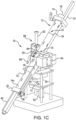
Figures 1A ,1B and1C are perspective views of a nuclear thermal propulsion fuel element packing device constructed in accordance with an embodiment of the present invention; -
Figure 2 is a perspective view of the thermal propulsion fuel element packing device shown inFigure 1 next to a containment box in which fuel element packing may occur; and -
Figures 3A ,3B and3C are perspective views of an alternate embodiment of a thermal propulsion fuel element packing device in accordance with the present invention. - Repeat use of reference characters in the present specification and drawings is intended to represent same or analogous features or elements of the invention according to the disclosure.
- The invention now will be described more fully hereinafter with reference to the accompanying drawings, in which some, but not, all embodiments of the invention are shown. Indeed, this invention may be embodied in many different forms and should not be construed as limited to the embodiments set forth herein; rather, these embodiments are provided so that this disclosure will satisfy applicable legal requirements. As used in the specification, and in the appended claims, the singular forms "a", "an", "the", include plural referents unless the context clearly dictates otherwise.
- Referring now to the Figures, a nuclear thermal propulsion fuel
element packing device 10 in accordance with the present invention includes astationary base 20, aclamp assembly 22 slidably secured thereto, a fuelelement support assembly 31/34, apowder reservoir assembly 60, acam assembly 50, and an eccentric weightvibratory motor 54, as shown inFigures 1A through 1C . As shown,clamp assembly 22 is received on a top surface ofstationary base 20 in a manner that allowsclamp assembly 22 to be selectively moved along a vertical axis with respect tostationary base 20 over a limited distance.Cam assembly 50 is mounted onstationary base 20 belowclamp assembly 22 such that rotation ofcam 51 bydrive motor 52 results in the raising and dropping motion ofclamp assembly 22 with regard tostationary base 20. The frequency with whichclamp assembly 22 rises and falls with respect to stationary base can be controlled by alternating the rate at which drivemotor 52 rotatescam 51. Eccentric weightvibratory motor 54 is affixed tobody 24 ofclamp assembly 22 so that vibrations are induced withinclamp assembly 22 simultaneously with the up and down motion of the clamp assembly caused by the rotation ofcam 51. The alternating raising and dropping motion of clamp assembly and vibrations induced byvibratory motor 54 facilitate filling acorresponding fuel element 12 with surrogate or fuel-bearing powders frompowder reservoir assembly 60, as discussed in greater detail below. Note, in alternate embodiments alternate vibration inducing assemblies can be used rather than an eccentric weight vibratory motor. - Still referring to
Figures 1A through 1C ,body 24 ofclamp assembly 22 defines afuel element bore 26 extending therethrough that is configured to receive ashell 14 of acorresponding fuel element 12 during the filling process. The fuel element support assembly is secured tobody 24 and includes asupport ramp 31 that extends upwardly frombody 24 adjacent the bottom perimeter of fuel element bore 26, and asupport clamp 11 that is slidably received thereon and tightened and loosed byhandle 13. As well, the support assembly includes aslide assembly 34 that includes astop plate 32 that is slidably received onslide arm 35 and is securable thereto in the desired position by way of aclamp 36. As shown, bothramp 31 andslide assembly 34 extend outwardly frombody 24 ofclamp assembly 22 at an angle equal to the angle defined by an intersection of a longitudinal center axis offuel element bore 26 and a vertical axis.Powder reservoir assembly 60 includes areservoir support 61 extending upwardly frombody 24 that is adjustably secured thereto by aclamp 66.Powder reservoir 62 is supported byreservoir support 61 and includes afill needle 64 extending downwardly therefrom. - As best seen in
Figures 1B and1C , during a fuel packing operation, a plurality offuel element shells 14 is slidably received within fuel element bore 26 ofclamp assembly 22. In the embodiment shown, fourfuel element shells 14 are affixed to each other by a series ofwelds 18. Each fuel element also includes a pair ofend caps 16 that are secured to therespective shell 14 by welds, and afill aperture 15 formed in a side wall of the shell. As shown, one of the outerfuel element shells 14a is receivedadjacent stop plate 32 and the adjustment ofstop plate 32 alongslide arm 34 is used to position afill aperture 15 of one of theother shells 14 adjacent the bottom end offill needle 64. Thefuel element shells 14 are further secured bysupport clamp 11, through which they pass. Fine adjustment offill aperture 15 with regard to fillneedle 64 can be adjusted by way of a set screw 40 (Figure 2 ) that is received in a threaded throughbore 38 that is formed instop plate 32. After thefuel element shell 14 being filled is secured in the desired position usingclamp elements 25, setscrew 40 can be removed and acounterweight 42 can be secured to the threaded throughbore 38 ofstop plate 32 to help balance theclamp assembly 22 andfuel element shells 14 during the filling operation. - Additionally, the position of
fill needle 64 with regard to fillaperture 15 may be adjusted by looseningclamp 66 of thepowder reservoir assembly 60 so that thereservoir support 61 may be adjusted. As noted above, clamp elements 25 (i.e., threaded stems) that extend inwardly intofuel element bore 26 are used to secure thecorresponding fuel element 12 with respect to thebody 24 ofclamp assembly 22 once the desired position offill needle 64 with respect to fillaperture 15 is achieved. As surrogate or fuel-bearing powder is flowed frompowder reservoir 62 throughfill needle 64 intofuel element shell 14,cam 51 is rotated at the desired rate andvibratory motor 54 includes vibrations withinclamp assembly 22 to help ensure that the powder flows in a continual manner and settles within the shell. Note,packing device 10 is preferably sized so that it may be disposed within a standard sizedradiological containment 70, as shown inFigure 2 , during fuel packing operations. As well, as shown inFigures 3A through 3C , alternate embodiments ofclamp assemblies 22a may be used with the remaining components ofpacking device 10 as needed for fuel packing operations on variously sized embodiments of fuel assemblies. - These and other modifications and variations to the invention may be practiced by those of ordinary skill in the art without departing from the scope of the invention, which is more particularly set forth in the appended claims. Furthermore, those of ordinary skill in the art will appreciate that the foregoing description is by way of example only, and it is not intended to limit the invention as further described in such appended claims. Therefore, the scope of the appended claims should not be limited to the exemplary description of the versions contained herein.
Claims (6)
- A packing device (10) for filling fuel elements (12) with a powder through a fill aperture (15) in an outer shell (14) of the fuel element (12), comprisinga stationary base (20) configured to be received on a support surface;a clamp assembly (22) including a body (24) defining a bore (26) therein, the bore (26) being configured to slidably receive a fuel element (12) therein, and an adjustment member configured to exert force on a corresponding fuel element (12) disposed within the bore (26) of the body (24), wherein the clamp assembly (22) is movable along a vertical axis with respect to the stationary base (20);characterised bya vibratory motor (54) affixed to the body (24) of the clamp assembly (22) so that the vibratory motor (54) induces vibration of the clamp assembly (22); anda powder reservoir assembly (60) including a powder reservoir (62), a fill needle (64) in fluid communication with the powder reservoir, (62) and a reservoir support (61) that is adjustably secured to the body (24) of the clamp assembly (22) so that the powder reservoir (62) can be adjusted vertically.
- The packing device (10) of claim 1, further comprising a cam assembly (50) including a cam (51) and a drive motor (52) configured to rotate the cam (51), wherein the cam assembly (50) is mounted on the stationary base (20) beneath the clamp assembly (22) so that rotation of the cam (51) alternatingly raises the clamp assembly (22) up along the vertical axis and subsequently drops the clamp assembly (22).
- The packing device (10) of claim 1, wherein the bore (26) in the body (24) of the clamp assembly (22) is at an angle with respect to the vertical axis.
- The packing device (10) of claim 3, wherein the bore (26) is a blind bore.
- The packing device (10) of claim 3, wherein the bore (26) is a through bore and the packing device further comprises a support ramp (31) extending both upwardly and outwardly from beneath an upper end of the bore (26), wherein the support ramp (31) is at the same angle with the vertical axis as is the bore (26).
- The packing device (10) of claim 5, wherein the packing device (10) further comprises a slide assembly (34) extending both downwardly and outwardly from beneath a lower end of the bore (26), the slide assembly (34) including a slide arm (35) and a stop plate (32) that is movable along the slide arm (34) and is configured to receive a bottom end of the corresponding fuel element (12), wherein the slide assembly(34) is at the same angle with the vertical axis as is the bore (26).
Applications Claiming Priority (3)
| Application Number | Priority Date | Filing Date | Title |
|---|---|---|---|
| US201862742809P | 2018-10-08 | 2018-10-08 | |
| EP19892152.0A EP3864672B1 (en) | 2018-10-08 | 2019-10-08 | Nuclear thermal propulsion fuel element packing device |
| PCT/US2019/055186 WO2020117364A2 (en) | 2018-10-08 | 2019-10-08 | Nuclear thermal propulsion fuel element packing device |
Related Parent Applications (2)
| Application Number | Title | Priority Date | Filing Date |
|---|---|---|---|
| EP19892152.0A Division-Into EP3864672B1 (en) | 2018-10-08 | 2019-10-08 | Nuclear thermal propulsion fuel element packing device |
| EP19892152.0A Division EP3864672B1 (en) | 2018-10-08 | 2019-10-08 | Nuclear thermal propulsion fuel element packing device |
Publications (3)
| Publication Number | Publication Date |
|---|---|
| EP4235692A1 EP4235692A1 (en) | 2023-08-30 |
| EP4235692C0 EP4235692C0 (en) | 2024-09-25 |
| EP4235692B1 true EP4235692B1 (en) | 2024-09-25 |
Family
ID=70052567
Family Applications (2)
| Application Number | Title | Priority Date | Filing Date |
|---|---|---|---|
| EP19892152.0A Active EP3864672B1 (en) | 2018-10-08 | 2019-10-08 | Nuclear thermal propulsion fuel element packing device |
| EP23179228.4A Active EP4235692B1 (en) | 2018-10-08 | 2019-10-08 | Nuclear thermal propulsion fuel element packing device |
Family Applications Before (1)
| Application Number | Title | Priority Date | Filing Date |
|---|---|---|---|
| EP19892152.0A Active EP3864672B1 (en) | 2018-10-08 | 2019-10-08 | Nuclear thermal propulsion fuel element packing device |
Country Status (4)
| Country | Link |
|---|---|
| US (1) | US11127508B2 (en) |
| EP (2) | EP3864672B1 (en) |
| CA (1) | CA3115636A1 (en) |
| WO (1) | WO2020117364A2 (en) |
Family Cites Families (29)
| Publication number | Priority date | Publication date | Assignee | Title |
|---|---|---|---|---|
| US1826926A (en) * | 1928-10-23 | 1931-10-13 | Hoepner Automatic Machinery Co | Machine for filling containers |
| GB968759A (en) * | 1962-08-28 | 1964-09-02 | Atomic Energy Authority Uk | Nuclear reactor valve |
| FR84968E (en) * | 1963-11-06 | 1965-05-21 | Commissariat Energie Atomique | Improvements in methods and devices for melting materials by induction |
| GB1051954A (en) * | 1964-04-08 | |||
| BE746119A (en) | 1970-02-18 | 1970-07-31 | Belgonucleaire Sa | FIXING CLAMP FOR PNEUMATIC VIBRATOR ( |
| JPS5014720B1 (en) | 1970-03-02 | 1975-05-29 | ||
| US3838716A (en) * | 1973-07-24 | 1974-10-01 | Us Interior | System for packing particulate material into long cylindrical containers |
| FR2296459A1 (en) | 1975-01-02 | 1976-07-30 | Commissariat Energie Atomique | ROTARY JAR POWDER HOMOGENIZER |
| US4158601A (en) * | 1977-05-12 | 1979-06-19 | Westinghouse Electric Corp. | Nuclear fuel pellet loading apparatus |
| US4235066A (en) * | 1978-05-30 | 1980-11-25 | General Electric Company | Nuclear fuel rod loading apparatus |
| JPS5848896A (en) * | 1981-09-18 | 1983-03-22 | 有限会社郷鋳造鉄工所 | Device for correcting automatically position of channel box to nuclear fuel assembly |
| US4495146A (en) * | 1981-12-07 | 1985-01-22 | Exxon Nuclear Company, Inc. | Spherical nuclear fuel loading system |
| FR2633435B1 (en) * | 1988-06-28 | 1990-11-09 | Framatome Sa | ADJUSTABLE PENCIL ADJUSTING CLUSTER FOR NUCLEAR FUEL ASSEMBLY |
| US4994231A (en) * | 1990-03-22 | 1991-02-19 | The Babcock & Wilcox Company | Apparatus for blending constituents of varying densities |
| US5122331A (en) * | 1991-05-13 | 1992-06-16 | Combustion Engineering, Inc. | Pellet stacking machine |
| US5251243A (en) * | 1992-08-21 | 1993-10-05 | Westinghouse Electric Corp. | Automatic fuel assembly loader |
| JPH11242094A (en) * | 1998-02-26 | 1999-09-07 | Hitachi Ltd | Inspection device for vibration filled fuel |
| FR2792544B1 (en) * | 1999-04-21 | 2001-08-03 | Cogema | POWDER MIXER |
| FR2834699B1 (en) * | 2002-01-15 | 2004-07-09 | Cogema | SUPPORT FOR RUNNING CYLINDRICAL ELEMENTS AND METHOD AND CONVEYOR USING SUCH SUPPORTS |
| US7593501B2 (en) * | 2005-01-06 | 2009-09-22 | Areva Np Inc. | Segment make-up system and method for manufacturing nuclear fuel rods |
| FR2909799A1 (en) | 2006-12-12 | 2008-06-13 | Commissariat Energie Atomique | METHOD AND MANUFACTURE OF NUCLEAR FUEL ELEMENTS AND CONTAINER FOR IMPLEMENTING SUCH A METHOD |
| FR2946119B1 (en) * | 2009-06-02 | 2015-03-20 | Areva Nc | CONNECTION DEVICE FOR JARRES FILLING SYSTEM FOR THE MANUFACTURE OF NUCLEAR FUEL. |
| FR2964091B1 (en) | 2010-08-26 | 2012-09-28 | Areva Nc | DEVICE FOR HANDLING FUTS, TRANSFER PLANT FOR POWDER MATERIAL, AND TRANSFER METHOD |
| US20130044850A1 (en) | 2011-08-19 | 2013-02-21 | Lewis A. Walton | Nuclear reactor refueling methods and apparatuses |
| FR3021805B1 (en) | 2014-05-27 | 2019-05-03 | Commissariat A L'energie Atomique Et Aux Energies Alternatives | PRESS FOR SHAPING PELLETS IN A RESTRICTED AND HOSTILE ENVIRONMENT AND METHOD OF ASSEMBLING THE PRESS |
| US10643754B2 (en) | 2016-03-14 | 2020-05-05 | Ultra Safe Nuclear Corporation | Passive reactivity control of nuclear thermal propulsion reactors |
| CN205629374U (en) | 2016-03-29 | 2016-10-12 | 洛阳高科钼钨材料有限公司 | Vibrating molybdenum powder filler device |
| US10614923B2 (en) | 2016-07-19 | 2020-04-07 | Battelle Energy Alliance, Llc | Methods of forming structures and fissile fuel materials by additive manufacturing |
| RU2020125869A (en) | 2018-01-22 | 2022-02-24 | Ультра Сейф Нуклеар Корпорейшн | COMPOSITE MODELER FOR NUCLEAR REACTOR SYSTEMS |
-
2019
- 2019-10-07 US US16/594,530 patent/US11127508B2/en active Active
- 2019-10-08 EP EP19892152.0A patent/EP3864672B1/en active Active
- 2019-10-08 CA CA3115636A patent/CA3115636A1/en active Pending
- 2019-10-08 EP EP23179228.4A patent/EP4235692B1/en active Active
- 2019-10-08 WO PCT/US2019/055186 patent/WO2020117364A2/en not_active Ceased
Also Published As
| Publication number | Publication date |
|---|---|
| US11127508B2 (en) | 2021-09-21 |
| EP3864672A4 (en) | 2022-05-18 |
| US20200111585A1 (en) | 2020-04-09 |
| EP3864672B1 (en) | 2023-08-09 |
| EP4235692C0 (en) | 2024-09-25 |
| WO2020117364A2 (en) | 2020-06-11 |
| CA3115636A1 (en) | 2020-06-11 |
| EP4235692A1 (en) | 2023-08-30 |
| EP3864672A2 (en) | 2021-08-18 |
| WO2020117364A3 (en) | 2020-07-02 |
Similar Documents
| Publication | Publication Date | Title |
|---|---|---|
| KR100466066B1 (en) | Hot dilation forming-use metal billet | |
| Hill et al. | Boundary-enhanced sedimentation due to settling convection | |
| EP1092473B2 (en) | Device for gravimetric testing of multichannel pipettes | |
| Takeda et al. | Angular momentum transfer in a protolunar disk | |
| RU2573494C2 (en) | Drum handling device, hardware for transfer of powders and method of transfer | |
| EP3491348B1 (en) | Method for weighing containers and relative weighing unit. | |
| EP3864672B1 (en) | Nuclear thermal propulsion fuel element packing device | |
| EP2685235A1 (en) | Machine for testing cushioning material for packaging | |
| CA2882917A1 (en) | System for radiographic inspection of welds | |
| DE3416764C2 (en) | Precision balance | |
| CN112985951A (en) | Geomechanics model test similar material automatic molding device and manufacturing system | |
| CN104990700B (en) | Explosion valve test device | |
| KR19980086753A (en) | Air liquefaction separator | |
| CN116256108A (en) | A Quantitative Trimming Method for Underwater Robot Center of Heavy Buoyancy | |
| Yoshida et al. | Estimation equation for sieving rate based on the model for undersized particles passing through vibrated particle bed | |
| US6617484B1 (en) | Containment and transportation of decommissioned nuclear reactor pressure vessels and the like | |
| JP2018523112A (en) | Component including vibration mitigating device, reactor pressure vessel assembly including component, and manufacturing method thereof | |
| CN113514214B (en) | Device and method for experimental measurement of additional mass matrix between annular fluid domain cylinder components of reactor | |
| Fujita et al. | Aseismic study on the reactor vessel of a fast breeder reactor | |
| KR102711234B1 (en) | Device for Ground Vibration Test with Soft Suspension Vibration Isolator Apparatus | |
| CN106323608B (en) | A kind of flutter valve static test tooling | |
| US7607341B2 (en) | Device for measuring the density of particles by flotation | |
| US20220011151A1 (en) | Increasing the weighing accuracy when weighing nested pharmaceutical containers | |
| CN113466086B (en) | Method for measuring bulk density and method for measuring bulk density of calcined product of radioactive waste liquid | |
| CN218787945U (en) | New-type dry-type material is beaten and is beaten subassembly |
Legal Events
| Date | Code | Title | Description |
|---|---|---|---|
| PUAI | Public reference made under article 153(3) epc to a published international application that has entered the european phase |
Free format text: ORIGINAL CODE: 0009012 |
|
| STAA | Information on the status of an ep patent application or granted ep patent |
Free format text: STATUS: REQUEST FOR EXAMINATION WAS MADE |
|
| 17P | Request for examination filed |
Effective date: 20230614 |
|
| AC | Divisional application: reference to earlier application |
Ref document number: 3864672 Country of ref document: EP Kind code of ref document: P |
|
| AK | Designated contracting states |
Kind code of ref document: A1 Designated state(s): AL AT BE BG CH CY CZ DE DK EE ES FI FR GB GR HR HU IE IS IT LI LT LU LV MC MK MT NL NO PL PT RO RS SE SI SK SM TR |
|
| GRAP | Despatch of communication of intention to grant a patent |
Free format text: ORIGINAL CODE: EPIDOSNIGR1 |
|
| STAA | Information on the status of an ep patent application or granted ep patent |
Free format text: STATUS: GRANT OF PATENT IS INTENDED |
|
| RIC1 | Information provided on ipc code assigned before grant |
Ipc: G21C 21/04 20060101ALI20240507BHEP Ipc: G21C 21/02 20060101ALI20240507BHEP Ipc: G21C 3/26 20060101ALI20240507BHEP Ipc: G21C 3/02 20060101AFI20240507BHEP |
|
| INTG | Intention to grant announced |
Effective date: 20240529 |
|
| GRAS | Grant fee paid |
Free format text: ORIGINAL CODE: EPIDOSNIGR3 |
|
| GRAA | (expected) grant |
Free format text: ORIGINAL CODE: 0009210 |
|
| STAA | Information on the status of an ep patent application or granted ep patent |
Free format text: STATUS: THE PATENT HAS BEEN GRANTED |
|
| AC | Divisional application: reference to earlier application |
Ref document number: 3864672 Country of ref document: EP Kind code of ref document: P |
|
| AK | Designated contracting states |
Kind code of ref document: B1 Designated state(s): AL AT BE BG CH CY CZ DE DK EE ES FI FR GB GR HR HU IE IS IT LI LT LU LV MC MK MT NL NO PL PT RO RS SE SI SK SM TR |
|
| REG | Reference to a national code |
Ref country code: GB Ref legal event code: FG4D |
|
| REG | Reference to a national code |
Ref country code: CH Ref legal event code: EP |
|
| REG | Reference to a national code |
Ref country code: DE Ref legal event code: R096 Ref document number: 602019059641 Country of ref document: DE |
|
| REG | Reference to a national code |
Ref country code: IE Ref legal event code: FG4D |
|
| U01 | Request for unitary effect filed |
Effective date: 20241006 |
|
| U07 | Unitary effect registered |
Designated state(s): AT BE BG DE DK EE FI FR IT LT LU LV MT NL PT RO SE SI Effective date: 20241028 |
|
| PG25 | Lapsed in a contracting state [announced via postgrant information from national office to epo] |
Ref country code: NO Free format text: LAPSE BECAUSE OF FAILURE TO SUBMIT A TRANSLATION OF THE DESCRIPTION OR TO PAY THE FEE WITHIN THE PRESCRIBED TIME-LIMIT Effective date: 20241225 |
|
| PG25 | Lapsed in a contracting state [announced via postgrant information from national office to epo] |
Ref country code: GR Free format text: LAPSE BECAUSE OF FAILURE TO SUBMIT A TRANSLATION OF THE DESCRIPTION OR TO PAY THE FEE WITHIN THE PRESCRIBED TIME-LIMIT Effective date: 20241226 |
|
| PG25 | Lapsed in a contracting state [announced via postgrant information from national office to epo] |
Ref country code: RS Free format text: LAPSE BECAUSE OF FAILURE TO SUBMIT A TRANSLATION OF THE DESCRIPTION OR TO PAY THE FEE WITHIN THE PRESCRIBED TIME-LIMIT Effective date: 20241225 |
|
| PG25 | Lapsed in a contracting state [announced via postgrant information from national office to epo] |
Ref country code: RS Free format text: LAPSE BECAUSE OF FAILURE TO SUBMIT A TRANSLATION OF THE DESCRIPTION OR TO PAY THE FEE WITHIN THE PRESCRIBED TIME-LIMIT Effective date: 20241225 Ref country code: NO Free format text: LAPSE BECAUSE OF FAILURE TO SUBMIT A TRANSLATION OF THE DESCRIPTION OR TO PAY THE FEE WITHIN THE PRESCRIBED TIME-LIMIT Effective date: 20241225 Ref country code: GR Free format text: LAPSE BECAUSE OF FAILURE TO SUBMIT A TRANSLATION OF THE DESCRIPTION OR TO PAY THE FEE WITHIN THE PRESCRIBED TIME-LIMIT Effective date: 20241226 |
|
| U21 | Renewal fee for the european patent with unitary effect paid with additional fee |
Year of fee payment: 6 Effective date: 20250227 |
|
| PG25 | Lapsed in a contracting state [announced via postgrant information from national office to epo] |
Ref country code: IS Free format text: LAPSE BECAUSE OF FAILURE TO SUBMIT A TRANSLATION OF THE DESCRIPTION OR TO PAY THE FEE WITHIN THE PRESCRIBED TIME-LIMIT Effective date: 20250125 |
|
| PG25 | Lapsed in a contracting state [announced via postgrant information from national office to epo] |
Ref country code: SM Free format text: LAPSE BECAUSE OF FAILURE TO SUBMIT A TRANSLATION OF THE DESCRIPTION OR TO PAY THE FEE WITHIN THE PRESCRIBED TIME-LIMIT Effective date: 20240925 |
|
| PG25 | Lapsed in a contracting state [announced via postgrant information from national office to epo] |
Ref country code: ES Free format text: LAPSE BECAUSE OF FAILURE TO SUBMIT A TRANSLATION OF THE DESCRIPTION OR TO PAY THE FEE WITHIN THE PRESCRIBED TIME-LIMIT Effective date: 20240925 |
|
| PG25 | Lapsed in a contracting state [announced via postgrant information from national office to epo] |
Ref country code: PL Free format text: LAPSE BECAUSE OF FAILURE TO SUBMIT A TRANSLATION OF THE DESCRIPTION OR TO PAY THE FEE WITHIN THE PRESCRIBED TIME-LIMIT Effective date: 20240925 Ref country code: CZ Free format text: LAPSE BECAUSE OF FAILURE TO SUBMIT A TRANSLATION OF THE DESCRIPTION OR TO PAY THE FEE WITHIN THE PRESCRIBED TIME-LIMIT Effective date: 20240925 |
|
| PG25 | Lapsed in a contracting state [announced via postgrant information from national office to epo] |
Ref country code: SK Free format text: LAPSE BECAUSE OF FAILURE TO SUBMIT A TRANSLATION OF THE DESCRIPTION OR TO PAY THE FEE WITHIN THE PRESCRIBED TIME-LIMIT Effective date: 20240925 |
|
| REG | Reference to a national code |
Ref country code: CH Ref legal event code: PL |
|
| PG25 | Lapsed in a contracting state [announced via postgrant information from national office to epo] |
Ref country code: MC Free format text: LAPSE BECAUSE OF FAILURE TO SUBMIT A TRANSLATION OF THE DESCRIPTION OR TO PAY THE FEE WITHIN THE PRESCRIBED TIME-LIMIT Effective date: 20240925 |
|
| PG25 | Lapsed in a contracting state [announced via postgrant information from national office to epo] |
Ref country code: CH Free format text: LAPSE BECAUSE OF NON-PAYMENT OF DUE FEES Effective date: 20241031 |
|
| PLBE | No opposition filed within time limit |
Free format text: ORIGINAL CODE: 0009261 |
|
| STAA | Information on the status of an ep patent application or granted ep patent |
Free format text: STATUS: NO OPPOSITION FILED WITHIN TIME LIMIT |
|
| 26N | No opposition filed |
Effective date: 20250626 |
|
| PG25 | Lapsed in a contracting state [announced via postgrant information from national office to epo] |
Ref country code: IE Free format text: LAPSE BECAUSE OF NON-PAYMENT OF DUE FEES Effective date: 20241008 |
|
| U21 | Renewal fee for the european patent with unitary effect paid with additional fee |
Year of fee payment: 7 Effective date: 20251126 |
|
| PGFP | Annual fee paid to national office [announced via postgrant information from national office to epo] |
Ref country code: GB Payment date: 20251127 Year of fee payment: 7 |
|
| PG25 | Lapsed in a contracting state [announced via postgrant information from national office to epo] |
Ref country code: HR Free format text: LAPSE BECAUSE OF FAILURE TO SUBMIT A TRANSLATION OF THE DESCRIPTION OR TO PAY THE FEE WITHIN THE PRESCRIBED TIME-LIMIT Effective date: 20240925 |
|
| PG25 | Lapsed in a contracting state [announced via postgrant information from national office to epo] |
Ref country code: CY Free format text: LAPSE BECAUSE OF FAILURE TO SUBMIT A TRANSLATION OF THE DESCRIPTION OR TO PAY THE FEE WITHIN THE PRESCRIBED TIME-LIMIT; INVALID AB INITIO Effective date: 20191008 |
|
| PG25 | Lapsed in a contracting state [announced via postgrant information from national office to epo] |
Ref country code: HU Free format text: LAPSE BECAUSE OF FAILURE TO SUBMIT A TRANSLATION OF THE DESCRIPTION OR TO PAY THE FEE WITHIN THE PRESCRIBED TIME-LIMIT; INVALID AB INITIO Effective date: 20191008 |
|
| PG25 | Lapsed in a contracting state [announced via postgrant information from national office to epo] |
Ref country code: TR Free format text: LAPSE BECAUSE OF FAILURE TO SUBMIT A TRANSLATION OF THE DESCRIPTION OR TO PAY THE FEE WITHIN THE PRESCRIBED TIME-LIMIT Effective date: 20240925 |