EP4235630A1 - Writing instrument - Google Patents
Writing instrument Download PDFInfo
- Publication number
- EP4235630A1 EP4235630A1 EP22158814.8A EP22158814A EP4235630A1 EP 4235630 A1 EP4235630 A1 EP 4235630A1 EP 22158814 A EP22158814 A EP 22158814A EP 4235630 A1 EP4235630 A1 EP 4235630A1
- Authority
- EP
- European Patent Office
- Prior art keywords
- magnetic field
- writing instrument
- pose
- page
- location
- Prior art date
- Legal status (The legal status is an assumption and is not a legal conclusion. Google has not performed a legal analysis and makes no representation as to the accuracy of the status listed.)
- Withdrawn
Links
Images


Classifications
-
- G—PHYSICS
- G09—EDUCATION; CRYPTOGRAPHY; DISPLAY; ADVERTISING; SEALS
- G09B—EDUCATIONAL OR DEMONSTRATION APPLIANCES; APPLIANCES FOR TEACHING, OR COMMUNICATING WITH, THE BLIND, DEAF OR MUTE; MODELS; PLANETARIA; GLOBES; MAPS; DIAGRAMS
- G09B11/00—Teaching hand-writing, shorthand, drawing, or painting
Definitions
- the embodiments described in the following disclosure relate to a writing instrument for writing gesture acquisition, and an associated training pad, method, data processing apparatus, system, computer program element, and computer readable medium.
- Air writing is a teacher-led activity, where students write letters or shapes in the air using arm movements. Students may also verbalize the words. Air writing enables students to remember letter formation techniques, which are motion oriented memories - an entirely different memory to the visual form of the letter shape. Air writing exercises also strengthen the arm and shoulder muscles in preparation for handwriting. This is important because weak muscles lead to bad handwriting formation.
- Air writing can also be used as a "stim" to help with student self-regulation. Writing letters and words in the air can be soothing for a hyperlexic child. Thus, air writing can enable hyperlexic children to remember, and to visualize the words that they hear. However, air writing techniques can be further improved.
- a writing instrument for writing gesture acquisition.
- the writing implement comprises an elongate body portion enabling a user to grip the writing instrument.
- the body portion comprises a proximal end and a distal end.
- the proximal end and the distal end define a longitudinal axis of the writing instrument.
- the writing implement comprises a first magnetic field sensor disposed on the surface of, or within, the writing instrument.
- the first magnetic field sensor is configured to output a first magnetic field measurement at least partially characterising a component of (i) a pose and/or (ii) a location of the proximal end of the writing instrument relative to a first magnetic field provided by a first magnet.
- the magnetic field is incident on the first magnetic field sensor.
- the writing implement comprises processing circuitry configured to transform the first magnetic field measurement into at least one pose and/or location sample of the writing instrument, and wireless communication circuitry configured to communicate the at least one pose and/or location sample to a data processing device.
- a training pad for writing gesture acquisition.
- the training pad comprises a first page comprising a first graphical symbol visible to a user, and a first magnet comprised on, or embedded in, or proximate to, the first page.
- the first magnet is configured to provide a first magnetic field defined by a first predetermined characteristic relative to the first graphical symbol.
- a method for automatic gesture recognition comprising:
- a data processing device for gesture recognition comprising a wireless data modem, a processor and a data memory.
- the wireless data modem is configured to receive a sequence of pose and/or location samples.
- the sequence of pose and/or location samples are based on a plurality of magnetic field measurements.
- the plurality of magnetic field measurements at least partially characterise a plurality of components of (i) a pose and/or (ii) a location of the proximal end of a writing instrument relative to a magnetic field incident on at least a first magnetic field sensor.
- the processor is configured to compare the sequence of pose and/or location samples to one or more segment records and to generate one, or more, segment comparison metrics characterising the conformity of the sequence of pose and/or location samples to the one or more segment records.
- a system comprising a writing implement according to the first aspect or its embodiments, a training pad according to the second aspect, or its embodiments, and a data processing device according to the fourth aspect, or its embodiments.
- a computer program element comprising machine readable instructions which, when executed by a processor, cause the processor to perform the method according to the third aspect, or its embodiments
- a seventh aspect there is provided a computer readable medium according to the sixth aspect.
- the pose and/or location of a writing instrument in a preset region relative to a writing training pad may be detected by monitoring changes in a magnetic field proximate to the writing instrument.
- an "air writing" writing task as used in an educational context, a student is asked by a teacher, or by an interface of a data processing device executing an air writing software training program, to use a writing instrument to follow the segments of an exemplary letter displayed on writing training pad.
- the signals describing the pose and/or location of the writing instrument relative to the magnetic field so detected may be used to generate a segment comparison metric. This enables a comparison of a segment of a letter written by the student to the intended form of the segment.
- the student or their teacher may use the segment comparison metric to judge the progress of a student in an air writing exercise.
- the pose and/or location information can be obtained from the writing instrument in a contactless manner.
- the pose and/or location information can be used in real-time to assist a student or their teacher to write through guided air writing sessions, eventually enabling the teacher to supervise the student less.
- Air writing exercises can be facilitated using a writing instrument comprising a magnetic sensor, and a training pad with passive magnetic tags.
- a writing instrument comprising a magnetic sensor, and a training pad with passive magnetic tags.
- This enables touchless pen pose and/or location estimation, relative to the training pad.
- One or more of the pages of the training pad contain a graphical character visible to a user that a user should attempt to duplicate in an air writing exercise using the writing instrument.
- the magnetic sensor detects or measures the magnetic field due to the passive magnetic tag comprised in the training pad.
- Dependent on the pose and/or location of the writing instrument relative to the training pad the magnetic sensor comprised in the writing instrument produces one or more variable output signals.
- variable output signal is received by software capable of determining the pose and/or location of the writing instrument.
- the software is capable of providing guidance to a user of writing instrument during an air writing exercise, based on the signals received from the writing instrument.
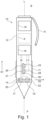
- Figure 1 schematically illustrates a side view internal view of a writing instrument according to an example of the first aspect.
- a writing instrument 10 for writing gesture acquisition comprising an elongate body portion 12 enabling a user to grip the writing instrument.
- the body portion comprises a proximal end P and a distal end D, the proximal end and the distal end defining a longitudinal axis L of the writing instrument.
- the writing instrument 10 further comprises a first magnetic field sensor 14 disposed on the surface 11 of, or within, the writing instrument.
- the first magnetic field sensor is configured to output a first magnetic field measurement at least partially characterising a component of (i) a pose and/or (ii) a location of the proximal end (P) of the writing instrument 10 relative to a first magnetic field M1 provided by a first magnet 46.
- the magnetic field is incident on the first magnetic field sensor 14.
- the writing instrument 10 further comprises processing circuitry 16 configured to transform the first magnetic field measurement into at least one pose and/or location samples of the writing instrument 10.
- the wireless communication circuitry 18 is configured to communicate the at least one pose and/or location sample to a data processing device 50.
- the writing implement 10 may have a circular, ovular, square, rectangular, pentagonal, hexagonal, or heptagonal cross-section along at least a portion.
- the form-factor of the elongate body 12 may change along the longitudinal axis L of the writing implement 10 to accommodate ergonomic variations or to enhance user comfort, for example (not illustrated).
- the total length of the writing instrument 10 in the longitudinal direction L is between 50mm and 200mm, and specifically 140mm.
- the maximum diameter of the writing implement is in the range of 6mm to 20mm, and specifically 9mm.
- the elongate body of the writing implement 10 may, for example, comprise injection moulded from polystyrene or polypropylene.
- the external surface of the writing instrument 10 comprises, near to its distal end D, a clip 6 for facilitating attachment to a user's pocket, for example.
- the writing implement 10 may comprise, near to the proximal end, a user grip comprised of a resilient material such as rubber.
- the user grip may be moulded to achieve an ergonomic match with a typical user profile, to enhance writing comfort.
- the processing circuitry 16 may comprise a microcontroller or microprocessor suitable for low energy, real-time processing such as an ARM (TM) Cortex A510, although skilled person will be able to use other microprocessors and circuitry.
- the wireless communication circuitry 18 comprises a chipset capable of performing bidirectional wired data communication with the processing circuitry 16, and bidirectional or unidirectional wireless communication with another node in a wireless communication network.
- the wireless communication circuitry 18 is capable of communicating via Bluetooth (TM), Bluetooth Low Energy (TM), WiFi (TM) (802.11a, b, g, n, ac, ad), Wireless USB, UMTS, LTE, ZigBee (TM), and the like.
- the writing instrument 10 also comprises a power source 8 for providing electrical power to the electronic circuitry of the writing instrument 10.
- the power source 8 is an alkaline battery (such as a AAA or an AA battery), a lithium battery, a Li-ion battery, and the like.
- the battery can be embedded in the writing instrument, and either be disposable or rechargeable.
- the writing instrument 10 further comprises a first magnetic field sensor 14, and optionally may comprise at least a further (second) magnetic field sensor 22.
- the first magnetic field sensor 14 disposed on a first sensor substrate 20 that is planar, and has a predefined orientation with respect to the longitudinal axis L of the writing instrument 10. As illustrated in the example of Figure 1 , the orientation of the first sensor substrate 20 is substantially orthogonal to the longitudinal axis L. Examples of the design of a magnetic field sensor will be discussed subsequently.
- the first magnetic field sensor 14 is configured to transfer a continuously variable signal to the processing circuitry 16 that, at least partially, characterises a component of the pose and/or location of the writing instrument 10 with respect to an external magnetic field M1 provided by a first magnet 46 of a training pad 40, for example.
- the first magnetic field sensor 14 can transfer the continuously variable signals in analogue form.
- the processing circuitry 16 comprises an analogue to digital converter to convert the continuously variable signals into digital form that can be processed by the processing circuitry 16.
- the first magnetic field sensor 14 natively converts the continuously variable signals to digital form before transmitting them to the processing circuitry 16.
- the first magnetic field sensor 14 has an axis or sensitivity SI, representing an axis along which the signals from the first magnetic field sensors 14 displays the greatest peak to peak variation for a unit of displacement.
- a user turns the writing instrument 10 on using an activation switch or gesture (not shown).
- the user pairs the writing instrument 10, so as to enable software at the remote data processing apparatus to receive signals characterising the component of the pose and/or location of the proximal end P of the writing instrument 10 relative to a magnetic field M1.
- the user then holds the writing instrument 10 proximate to a training pad 40 (to be discussed subsequently).
- the training pad 40 comprises at least one magnet 46a.
- variations in the strength of a magnetic field M1 are detected by at least the first magnetic field sensor 14 to characterise component of the pose and/or location of the proximal end of the writing instrument.
- the magnetic field sensor 14 is sampled at a sampling rate enabling reproduction of the formation of a segment of an air writing exercise.
- a higher sampling rate of the magnetic field sensor 14 results in a higher required data processing and transfer rate to an external data processing apparatus.
- the processing circuitry 16 may sample the magnetic field sensor 14 of at a frequency in the ranges 5-10 Hz, 10-20 Hz, 20-50 Hz, 50-75 Hz, 75-100 Hz, 100-500 Hz, 500 Hz -1 kHz, or 1 - 10 kHz.
- the processing circuitry 16 is configured to identify a page of a training pad 40 based on the magnitude and/or direction of a magnetic field M1 detected by at least the first magnetic field sensor 14, for example by comparing the magnitude and/or direction of a magnetic field M1 to a lookup table that defines a relationship between magnetic field characteristics and the pages of the training pad 40.
- the processing circuitry 16 is configured to transmit the identified page to external data processing apparatus.
- no determination of the page of the training pad is made by the writing instrument, with the determination being computed at the external data processing apparatus.
- FIG 2 schematically illustrates a coordinate system of a writing implement relative to a magnet.
- a first page 42 of a training pad 40 comprises a first magnet 46 that establishes a magnetic field M1 illustrated by the exemplary magnetic field lines.
- the first magnet 46 is arranged on the first page 42 of the training pad 40 in a predefined orientation relative to the graphical symbol 44. As the writing implement 10 is moved to different locations of the graphical symbol 44, at least the first magnetic field sensor 14 of the writing implement 10 will characterise the corresponding variation in the magnetic field M1.
- the plane of the first page 42 of the training pad 40 defines a 2D domain around which the writing instrument 10 may move when an air writing exercise is in progress.
- the 2D domain comprises lateral locations (x, y).
- the vertical displacement (z) of the proximal end P of the writing implement 10 characterises the height of the proximal end of the writing implement above the first page 42 of the training pad 40.
- the locations relative to the training pad 40 (x,y,z) are referenced to an origin represented, for example, by the corner of the first page 42
- the locations (x,y,z) are relatively defined.
- the locations (x,y) are sufficient to characterise a set of location samples defining the outcome of a writing exercise, provided only monitoring the fidelity of the reproduction of the graphical symbol 44 by a student in the plane of the first page 42 is relevant.
- the locations (x,y,z) of the proximal end of the writing instrument 10 are used to generate a location sample without a characterisation of component of the pose of the writing implement 10.
- Figure 2 illustrates one exemplary definition of the pose of a writing implement 10.
- the pose of the writing can in turn is defined according to the azimuth angle ⁇ ° and the angle of elevation ⁇ ° of the longitudinal axis L of the writing implement 10.
- Tracking the pose of the writing instrument 10 during an air writing exercise is not essential, because fidelity to an example graphical symbol may be judged by software using only the 2D location of the writing instrument 10, for example.
- monitoring of the pose may enable a teacher to diagnose poor grip posture when performing the air writing exercise.
- the writing instrument 10 is configured to perform writing gesture acquisition based on monitoring a change of orientation of the longitudinal axis L and/or the location of the proximal end P of the writing instrument relative to the magnetic field of the first magnet 46, in use.
- a range of different types of magnetic field sensing elements 15a-d may be used in writing implement 10.
- a Hall element is based on the phenomenon that the electromotive force appears in a direction orthogonal to both the current and the magnetic field when applying a magnetic field is perpendicular to the current to the object through which that current is flowing.
- a current is applied to a thin film semiconductor, a voltage corresponding to the magnetic flux density and its direction is output according to the Hall effect.
- the Hall effect may, therefore, be used to detect a magnetic field. Hall elements can detect a magnetic field even in the case of a static magnetic field with no time-varying change in magnetic flux density at a given location.
- MI sensors are capable to measure the large change of electrical impedance experienced by a soft magnetic material when subjected to an external magnetic field. MI sensors may detect small magnetic fields.
- Giant magnetoresistance (GMR) -based magnetic sensors use materials comprising magnetic micro-or nano metre -sized particles and detect magnetic fringing fields of the particles.
- GMR sensors are sensitive, inexpensive, and portable, as well as being compatible with standard silicon planar integrated circuit technology.
- a 2D magnetic field sensor comprising GMR spin valves may be integrated on an ultra-thin polyimide foil as discussed the paper " Magnetosensitive E-skins with directional perception for augmented reality", by Ca ⁇ ón Bermudez et. al, 19 January 2018, “Science Advances” 2018; 4,:eaao2623 .
- AMR anisotropic magneto resistive sensor
- Figure 3 schematically illustrates an example of a magnetic field sensing element 15a, used as a single magnetic field sensing element 15a of a first magnetic field sensor 14.
- the angle ⁇ ° in Figure 3 represents the angle between a magnetic field vector (magnetic moment) of the applied magnetic field M1 and the direction of current flow through the magnetic field sensing element 15a.
- This type of magnetic field sensing element 15a changes resistance with a cos 2 ⁇ relationship, where ⁇ is the angle between the direction of the flow of current through the magnetic field sensing element 15a, and the direction of the magnetic field. Therefore, this type of magnetic field sensing element 15a tends to have an elongate form to ensure that the current flow has a well definable direction relative to an incident magnetic field.
- the magnetic field sensing element 15a is an anisotropic magnetoresistance (AMR) sensor.
- the magnetic field sensing element 15a is a GMR sensing element.
- the magnetic field sensing element 15a is a Hall sensing element.
- the magnetic field sensing element 15a a magneto-impedance (MI) sensing element comprising amorphous wires or glass coated microwires.
- Figure 4 schematically illustrates a first magnetic field sensor 14 and a second magnetic field sensor 22.
- Each of the first magnetic field sensor 14 and a second magnetic field sensor 22 comprise four magnetic field sensing elements 15a-15h in corresponding first 17 and second 19 resistive bridge configurations, specifically as two Wheatstone bridges.
- Figure 4 simultaneous illustrates an example of a spatial relationship and an electrical schematic relationship between the four magnetic field sensing elements 15a-15d when arranged on a planar sensor substrate 20.
- the planar sensor substrate is a polyimide foil.
- a skilled person will appreciate that other types of magnetic field sensing elements 15a-15d that change their resistance based on the angle of incidence of the magnetic field can also be arranged in a resistive bridge configuration.
- the exemplary incident direction of the magnetic field is shown by arrow M1.
- Four identical magnetic field sensing elements 15a-d are physically arranged with a spatially coplanar relationship on a first sensor substrate 20.
- the first sensor substrate 20 is a planar polyimide foil.
- a direct current supply voltage V SX is applied to the top and bottom connections of the resistive bridge 17.
- the first resistive bridge configuration 17 is exposed to an incident magnetic field M1.
- the voltage across the left and right connections of the resistive bridge 17 is measured, to obtain a voltage that is connected to the field angular orientation ⁇ X relative to the orientation of current flow in the magnetic field sensing elements 15a-d, and the field strength M1 of the first resistive bridge configuration 17.
- the measured voltage when an incident magnetic field M1 is not present, the measured voltage is zero, or comprises a small DC offset.
- the angle between the direction of physical current flow in the magnetic field sensing elements 15a-d and the direction of the magnetization of the magnetic field M1 changes, a differential voltage appears across the left and right terminals of the contacts. If the direction of the magnetic field M1 remains constant and the angular orientation of the substrate 20 varies through 360 degrees, a sinusoidal output voltage V SX results.
- the substrate 20 is aligned relative to the longitudinal axis L of the writing instrument 10 to enable the linear region of the output voltage (for example, corresponding to an angular deflection ⁇ relative to the direction of the magnetic field M1 of between plus and minus 45 degrees) V SX to be used for pose and/or location measurement of the writing implement 10.
- V SX linear region of the output voltage
- a second magnetic field sensor 22 comprised of a second resistive bridge configuration 19 is provided on the first sensor substrate 20 to enable 2D location sensing in, for example, the (x,y) plane.
- the magnetic field sensing elements 15e-h of the second resistive bridge configuration 19 are orientated on the first sensor substrate 20 differently to the magnetic field sensing elements 15a-d of the first resistive bridge configuration 17. This means that the direction of current flow through each magnetic field sensing element 15e-h of the second magnetic field sensor 22 is different compared to the direction of current flow through magnetic field sensing elements 15a-d of the first resistive bridge configuration 17, enabling the detection of (x,y) translation of the first sensor substrate 20.
- first and second magnetic field sensors described above is not essential.
- some forms of magnetic field sensor do not require a resistive bridge.
- a magnetic field sensor 14 is comprised of a single magnetic field sensing element 15a.
- the first magnetic field sensor 14 and the second magnetic field sensor 22 do not need to be collocated on the same sensor substrate.
- the first magnetic field sensor 14 and the second magnetic field sensor 22 can be located on separate sensor substrates.
- Figure 5 schematically illustrates an example of a position sensing signal from the resistive bridge of Figure 4 .
- the first resistive bridge configuration 17 of this example outputs a sinusoidal waveform. Therefore, the level of the output voltage from the first resistive bridge configuration 17 enables a characterisation of the component of the pose and/or location information of the writing instrument 10 in relative to a plane of interest.
- the output of the first resistive bridge configuration 17 may be digitised and transmitted to an external data processing device for determining the accuracy of a written segment during an air writing exercise.
- the at least one magnetic field sensing element 15a comprised in the writing implement 10 is configured to change its resistance based on the direction of the incident of the magnetic field M1.
- four magnetic field sensing elements 15a-d are arranged in a spatially coplanar relationship and are mutually configured as a resistive bridge configuration 17, to form a first magnetic field sensor 14.
- the first magnetic field sensor 14 is configured to discriminate between the x and y in-plane components of the magnetic field.
- a further four magnetic field sensing elements 15e-h of the second magnetic field sensor 22 are arranged in a spatially coplanar relationship to the magnetic field sensing element 15a-d (for example, on the same polyimide substrate as the magnetic field sensing elements of the first resistive bridge configuration 17), to form a second resistive bridge configuration 19.
- the first resistive bridge configuration 17 and the second resistive bridge configuration 19 mounted in the same plane are fed with phase-shifted voltage signals.
- the first resistive bridge configuration 17 may be driven by a signal having a 90 degree phase shift to the signal driving the second resistive bridge configuration 19. The benefit of this is that improved angular resolution of the magnetic field M1 is possible.
- first resistive bridge configuration 17 thus enables the localisation of the writing instrument 10 in the first 2D plane.
- second resistive bridge configuration 19 coplanar to the first resistive bridge configuration 17 enables improved position and/or angular accuracy of resolution in the first 2D plane.
- the writing instrument 10 further comprises a second magnetic field sensor 22 configured to output a second magnetic field measurement.
- the second magnetic field sensor 22 is disposed on the surface 11 of, or within, the writing instrument.
- the second magnetic field measurement at least partially characterises a second component of the (i) pose and/or (ii) the location of the proximal end of the writing instrument relative to a magnetic field provided by at least the first magnet 46 incident on the second magnetic field sensor 22.
- a first magnetic field sensor 14 in combination with a second magnetic field sensor 22 may comprise a first resistive bridge configuration 17 and a second resistive bridge configuration 19. If the resistive bridge configurations 17 and 19 are Wheatstone bridges, then the total of eight magnetic field sensing elements 15 are provided on a planar first sensor substrate 20. Each of the magnetic field sensing elements 15 has a well-defined magnetic anisotropic axis. In an example, the magnetic field sensing elements 15 are thus integrated in Wheatstone bridges having orthogonal sensitivity axes to realize a 2D motion sensor.
- the first magnetic field sensor 14 comprises a first plurality of magnetic field sensing elements 15a,b electronically coupled in a first resistive bridge configuration 17.
- the second magnetic field sensor 22 comprises a second plurality of magnetic field sensing elements 23a,b electronically coupled in a second resistive bridge configuration 19.
- the first and second magnetic field sensors are arranged on a first sensor substrate 20 in a coplanar configuration.
- At least one of the magnetic field sensing elements 15a,b of the first plurality of magnetic field sensing elements are arranged on the first sensor substrate 20 along a first sensitivity axis S1. At least one of the magnetic field sensing elements 23a,b of the second plurality of magnetic field sensing elements are arranged on the first sensor substrate 20 along a second sensitivity axis S2.
- the first sensitivity axis S1 is orthogonal to the second sensitivity axis S2.
- a third magnetic field sensor 24 configured to output a third magnetic field measurement.
- the third magnetic field sensor comprises a third plurality of magnetic field sensing elements coupled in a third resistive bridge configuration 26, and a fourth magnetic field sensor 28 configured to output a fourth magnetic field measurement.
- the fourth magnetic field sensor 28 comprises a fourth plurality of magnetic field sensing elements coupled in a fourth resistive bridge configuration 31.
- the third and fourth magnetic field sensors are arranged on a second sensor substrate (30) in a coplanar configuration.
- the third magnetic field sensor 24 and the fourth magnetic field sensor 28 are sensors of the same type as illustrated in Figure 4 , with the difference that the second sensor substrate 30 upon which the third magnetic field sensor 24 and the fourth magnetic field sensor 28 are supported has a different, for example an orthogonal, orientation to the first sensor substrate.
- the first sensor substrate 20 is orthogonal to the second sensor substrate 30.
- Providing a second sensor substrate 30 comprising a third resistive bridge configuration 26 and a fourth resistive bridge configuration 31 coplanar with the third resistive bridge configuration 26 enables 3D information to be determined.
- An example of 3D information is the vertical displacement of the writing implement 10 in the z direction (as illustrated in Figure 1 ) above the writing surface. By sampling the vertical displacement of the writing implement 10 as an air writing exercise is being performed, the air writing trajectory can be more accurately identified.
- the third resistive bridge configuration 26 and a fourth resistive bridge configuration 31 comprised on the second sensor substrate 30 illustrated in Figure 1 .
- the third resistive bridge configuration 26 and a fourth resistive bridge configuration 31 are configured to detect a third (z) component of motion of the longitudinal axis of the writing instrument 10 relative to at least a first magnetic field M1, and/or an angle of elevation ⁇ ° of the writing instrument 10.
- the first 14 and second 22 magnetic field sensors each comprise a Hall sensor, an anisotropic magnetoresistance sensor, a giant magnetoresistance sensor, or an amorphous wire magneto impedance sensor.
- the first 14 and second 22 magnetic field sensors are thin-film magnetic sensors.
- At least a first magnetic field sensor 14 may be conformed to the elongate body portion of the writing instrument 10. In an example, at least a first magnetic field sensor 14 may be distributed as a strip along the longitudinal axis of the writing instrument 10.
- the processing circuitry 16 of the writing instrument 10 is configured to obtain a plurality of first magnetic field measurements during a motion segment of the writing instrument 10.
- the processing circuitry 16 is configured to transform the plurality of first magnetic field measurements into a corresponding plurality of pose and/or location samples characterising a motion segment of the writing instrument.
- the processing circuitry 16 receives time-indexed samples of the signal output from at least the first magnetic field sensor 14, and/or in addition the second magnetic field sensor 22, the third magnetic field sensor 26, and the fourth magnetic field sensor 28.
- the time-indexed samples comprising magnetic field measurements characterising the pose and/or location of the writing instrument may be transmitted as data tuples to a data processing device 74 for comparison to segment records.
- the samples of the magnetic field measurements obtained by the magnetic field sensors may be pre-processed, normalised, and the like.
- Figure 6 schematically illustrates a plan view of an example of a training pad 40 according to the second aspect.
- the training pad 40 has the form of a notepad with each page showing a graphical symbol 44 for use in an air writing exercise.
- a first page 42 of the training pad 40 has a first magnet 46 capable of inducing a first magnetic field M1 attached, or embedded in, the first page 42.
- the first magnet 46 has a unique shape, or strength, enabling its magnetic field M1 to be distinguished from other magnets in the training pad 40.
- the first magnetic field M1 of the first magnet 46 of the training pad 40 is configured to detected by the at least one magnetic field sensor 14 of a writing instrument 10 according to the first aspect or its embodiments.
- the first page 42 of the training pad 40 may be a paper, cardboard, or flexible plastic page.
- the first magnet 46 may be embedded inside the first page 42, or adhesively attached to an upper or lower surface of the first page 42.
- the first page 42 has printed upon its visible surface a graphical symbol 44 for use in an air writing exercise.
- the graphical symbol 44 is in the form of a letter "A".
- a letter "A” comprises three segments - two mutually opposed slanting segments and a horizontal cross segment.
- the relationship of the graphical symbol 44 to the first magnet 46, and the first magnetic field M1 is illustrated in Figure 6 .
- At least the first magnetic field sensor 14 detects a change in the orientation and/or flux of the first magnetic field M1 whilst tracing the three segments.
- a sequence of pose and/or location samples obtained which may be compared to a set of segment records in a data processing device, in order to identify the letter that a student attempted to air write.
- a training pad 40 for writing gesture acquisition comprises a first page 42 comprising a first graphical symbol 44 visible to a user, and a first magnet 46 comprised on, or embedded in, or proximate to, the first page.
- the first magnet is configured to provide a first magnetic field M1 defined by a first predetermined characteristic relative to the first graphical symbol.
- the first predetermined characteristic may be, for example, the absolute magnetic field strength of the first magnet 46, or the spatial disposition first magnet 46 in the plane defined by the first page 42 of the training pad 40.
- a predetermined characteristic defining the first magnetic field M1 may be defined by a first magnet 46 having a triangular, circular, or arbitrary shape in the plane of the first page 42 relative to other pages of the training pad 40. If the first magnetic field M1 has a unique predetermined characteristic relative to other pages of training pad 40, magnetic field strength measurements using the writing instrument 10 can be used to identify which page of the training pad 40 is currently being displayed to a user.
- the training pad 40 further comprises a second page 48.
- An attachment region 50b of the second page is attached to the first page 42 along a corresponding attachment region 50a of the first page.
- the second page 48 comprises a second graphical symbol.
- the training pad 40 further comprises a second magnet 52 comprised on, or embedded in, the second page.
- the second magnet 52 is configured to provide a second magnetic field M2 defined by a second predetermined characteristic relative to the second graphical symbol.
- Figure 7 schematically illustrates a side view of the training pad of Figure 6 .
- the training pad 40 may comprise of a first page 42 attached to a second page 48 along attachment regions 50a, 50b, respectively.
- the first page 42 and the second page 48 may be attached using an adhesive strip, a ring binding, a staple, and the like.
- the second page 48 comprises a second magnet 52.
- the second magnet 52 has a slightly greater lateral spatial extent as opposed to the first magnet 46.
- This is an example of a second predetermined characteristic - in other words, the second magnet 52 has a different spatial extent as compared to the first magnet 46, and its magnetic field lines will be distributed differently in the vicinity of the second page 48 of the training pad 40.
- the second magnetic field M2 is not illustrated in Figure 7 but it may be assumed to have a greater spatial extent as compared to the first magnetic field 46 in the illustrated example.
- the training pad 40 is configured such that when the first page 42 overlies the second page 48, the first 46 and second magnets 52 are aligned with each other along a common axis that is substantially perpendicular to the first and second pages, such that a resultant magnetic field M3 comprised of at least the first M1 and second M2 magnetic fields is generated.
- the magnets of the training pad are overlaid in substantially the same lateral location on each page of the training pad such that when the pages of the training pad are closed, the magnets are aligned such that the generate a stronger magnetic field.
- This magnetic field can, for example, identify that the training pad 40 is closed, or open at a determinable page, for example.
- the training pad 40, the magnitude and/or orientation of the first magnetic field M1 is configured to be distinguishable from the magnitude and/or orientation of the second magnetic field M2, thus causing a writing implement 10 comprising at least a first magnetic field sensor 14 to detect the resultant magnetic field M3 if the training pad is in a first state.
- the first page 42 overlies the second page 48.
- the writing instrument 10 can detect the second magnetic field M2 that is different to the resultant magnetic field M3, if the training pad 40 is in a second state, in which the first page 42 does not overly the second page 48.
- the first magnet 46 is permanent magnet tape.
- the first magnet 46 comprises magneto-impedance amorphous wires, or glass coated micro-wires. Such tags have a thickness not exceeding a few hundred microns.
- Figure 8 schematically illustrates a method according to the third aspect.
- a method 60 for automatic gesture recognition comprising:
- a user may hold the writing instrument 10 over the training pad 40.
- a first page 42 of the training 40 comprises a graphical symbol 44 to a user that is to be written.
- At least the first magnetic field sensor 14 and a second magnetic field sensor 22 comprised in the writing instrument 10 reads the magnetic field M1 first page 42 of the training pad 40.
- the first magnetic field sensor 14 and the second magnetic field sensor 22 are provided as a corresponding first resistive bridge configuration 17 and second resistive bridge configuration 19.
- the variations of the magnetic field M1 of the first magnet 46, detected by at least the first magnetic field sensor 14 and the second magnetic field sensor 22, represent sampled components of a pose and/or a location of the proximal end of the writing instrument 10.
- the processing circuitry 16 and the wireless communication circuit 18 transmit the sampled components of a pose and/or a location of the proximal end of the writing instrument 10 to, for example, a data processing device 70.
- software executing within the data processing device 70 can identify the unique page of the training pad 40 by comparison of the measured magnetic field M1.
- the method 60 further comprises:
- Figure 9a schematically illustrates an example data processing flow of pose and/or location signals according to the method of the third aspect.
- a sequence of pose and/or location samples 68 measured by a writing instrument 10 according to the first aspect or its embodiments is received at a data processing device 70.
- the sequence of pose and/or location samples may comprise time-indexed tuples with measurements representing the azimuth and elevation angle of the writing instrument 10 (useful for defining the pose of the writing instrument 10), and lateral displacement samples defining the location of the proximal tip of the pen according to orthogonal coordinates (x, y, z), .
- a data memory 76 of the data processing device 70 may comprise a plurality of segment records 65. For each page of a training pad 40, records comprising indicative sequences of sampled pose and/or location samples reference to the graphical symbol 44 illustrated on the relevant page 42 of the training pad 40 are compared to the sequence of pose and/or location samples received 62 by the data processing device 70.
- One or more segment comparison metrics 67 are generated by comparing the sequence 68 with one or more of the segment records 65.
- Each of the segment comparison metrics 67 is a similarity measure capable of enabling a comparison of how close an air written letter is to the graphical symbol 44 included on the relevant page 42 of the training pad 40.
- the obtained sequence of pose and/or location samples may be compared to one or more of the segment records using many time domain or frequency domain signal processing techniques for spatial trajectory comparison known to a person skilled in the art, such as Kalman filtering or least squares estimation.
- an intended segment provided as a result in this case shows that the graphical symbol 44 of "A", as displayed on the first page 42 of the training pad 40 has been correctly written to within a 5% accuracy of the specimen segment record, representing a good result.
- the method 60 further comprises:
- the measurement of the first magnetic field M1 of the first page 42 of the training pad 40 enables identification of the first page 42 of the training pad at a data processing device 70.
- the data processing device 70 causes, in response, a user display, such as a tablet or smart whiteboard, to display an image of an intended segment to be traced during an air writing exercise.
- the method 60 further comprises:
- a user may flip a page on the training pad 40 to a first page 42 containing a desired graphical symbol 44.
- the user holds the writing instrument 10 over the training pad 40.
- An initial task is for an external data processing device 70 that is paired to the writing instrument 10 to identify which page of training pad 40 a user of the writing instrument 10 has reached.
- a magnetic sensor of the writing instrument 10 is therefore used to sense a first magnetic field M1.
- the user holds the writing instrument 10 at a predetermined location on the first page 42 of the training pad 40.
- the writing instrument 10 measures the first magnetic field M1.
- the user may be instructed to trace the end of the along a predefined path or line displayed on the first page 42, and the writing instrument obtains a calibration sample of the first magnetic field M1 sufficient to identify the capable of uniquely identifying the first page 42 of the training pad to software executing in the external data processing device 70.
- the writing instrument 10 transmits the samples of the first magnetic field 70 to the external data processing device 70.
- the external data processing device 70 make a determination of which page the training pad 40 has been set to.
- the external data processing device 70 looks up which graphical symbol 44a-e is being displayed on the first page 42.
- the software of the external data processing device 70 does not transmit any further instructions to a user of the writing instrument 10. Instead, the software of the external data processing device 70 detects that a user is performing an attempt at writing on the graphical symbol 44 of the first page 42 as the external data processing device 70 begins to receive samples of pose and/or location data from the writing instrument 10. The software of the external data processing device 70 performs processing of the received sequence of pose and/or location samples obtained from the plurality of magnetic field measurements to one or more segment records as discussed above.
- the software of the external data processing device 70 displays, on a user display operatively connected to the data processing device 70, an example of a segment or graphical symbol to be traced during an air writing exercise corresponding to the graphical symbol 44 present on the first page 42 identified by reading the magnetic field unique to the first page 42.
- the software of the external data processing device 70 can progressively instruct a student to complete one or more segments of the air writing exercise, and to correspondingly receive the sequence of pose and/or location samples resulting from each segment of the air writing exercise.
- the software of the external data processing device 70 can progressively compare pose and/or location samples received from writing instrument 10 with a set of ideal pose and/or location samples of each segment comprised in the set of segment records 65.
- the software of the external data processing device can provide a user with a score based on the comparison of the pose and/or location samples received from writing instrument 10 with a set of ideal pose and/or location samples of each segment comprised in the set of segment records 65.
- the software of the external data processing device 70 can instruct the user to turn to the next page of the training pad 40 if the score exceeds a predetermined threshold.
- the software of the external data processing device 70 can instruct the user to repeat the air writing exercise of the first page 42 if the score is lower than a predetermined threshold.
- the software of the external data processing device 70 can instruct the user to repeat the air writing exercise of the first page 42 a plurality of times, such as ten or twenty times.
- a score is calculated, as previously, score based on the comparison of the pose and/or location samples received from writing instrument 10 with a set of ideal pose and/or location samples of each segment comprised in the set of segment records 65.
- the software of the external data processing device 70 can track the progressive change in ability of the student at each stage of the repeated air writing exercise, and, for example, issue audio or graphical feedback messages via user display that encourage the student to continue with the exercise, or ask a supervising teacher to assist the student, or provide advice on completing a specific segment or letter of the air writing exercise that appears to be causing a student difficulty.
- the audio or graphical feedback messages provided to the student via the user display 77 may be presented a simple graphical pop-up boxes with text or ordinary speech.
- the audio or graphical feedback messages can be integrated into a form of cartoon or game, to improve student persistence with the air writing exercise.
- the method 60 further comprises: updating a unique user record 65a with the one or more segment records 65.
- a unique user record 65a of the segment records may enable a user of the writing instrument to save their attempts at a specific page of the training pad 40 over time, to enable tracking of improvement when performing a writing exercises.
- Figure 9b schematically illustrates an example of the system deployed in a classroom with a plurality of users.
- a plurality of users manipulate a plurality of writing instruments 10a-10d in the vicinity of their own training pads 40a-d.
- Each writing instrument 10a-10d communicates a sequence of pose and/or location information obtained at each of the writing instruments 10a-10d to a wireless network node 78, and thereby to a data processing device 70.
- Unique user records 65a-d may be provided for each of the plurality of users, enabling a teacher to monitor the progress of an entire class during an air writing exercise.
- Figure 10 schematically illustrates an example of a user display dialog box.
- the graphical symbols 44a-44e may be comprised on pages of a training pad 40.
- the user display dialog box may be displayed via a user interface of a data processing device 70 to provide instructions to a student when performing the air writing device using the training pad 40.
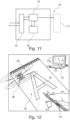
- Figure 11 schematically illustrates an example of a data processing apparatus according to the fourth aspect.
- a data processing device 70 for gesture recognition comprising a wireless data modem 72, processor 74, and a data memory 76.
- the wireless data modem 72 is configured to receive a sequence of pose and/or location samples.
- the sequence of pose and/or location samples are based on a plurality of magnetic field measurements, wherein the plurality of magnetic field measurements at least partially characterise a plurality of components of (i) a pose and/or (ii) a location of the proximal end P of a writing instrument 10 relative to a magnetic field M1 incident on at least a first magnetic field sensor 14.
- the processor 74 is configured to compare the sequence of pose and/or location samples to one or more segment records 65 and to generate one, or more, segment comparison metrics 67 characterising the conformity of the sequence of pose and/or location samples to the one or more segment records 65.
- the data processing device is one of a smartphone, tablet, a desktop or laptop personal computer, and the like.
- the data processing device is configured to execute the method according to the third aspect, or its embodiments.
- Figure 12 schematically illustrates a use of the system according to a fifth aspect.
- a system 80 comprising a writing implement 10 according to the first aspect, or its embodiments, a training pad 30 according to the second aspect, or its embodiments, and a data processing device 70 according to the fourth aspect.
- a computer program element comprising machine readable instructions which, when executed by a processor, cause the processor to perform the method according to the third aspect, or its embodiments.
- a seventh aspect there is provided a computer readable medium according to the sixth aspect.
- references throughout the preceding specification to "one embodiment”, “an embodiment”, “one example” or “an example”, “one aspect” or “an aspect” means that a particular feature, structure, or characteristic described in connection with the embodiment or example is included in at least one embodiment of the present disclosure.
- appearances of the phrases “in one embodiment”, “in an embodiment”, “one example” or “an example”, “one aspect” or “an aspect” in various places throughout this specification are not necessarily all referring to the same embodiment or example.
Landscapes
- Engineering & Computer Science (AREA)
- Business, Economics & Management (AREA)
- Physics & Mathematics (AREA)
- Educational Administration (AREA)
- Educational Technology (AREA)
- General Physics & Mathematics (AREA)
- Theoretical Computer Science (AREA)
- Position Input By Displaying (AREA)
Abstract
Description
- The embodiments described in the following disclosure relate to a writing instrument for writing gesture acquisition, and an associated training pad, method, data processing apparatus, system, computer program element, and computer readable medium.
- Monitoring and coaching students during writing exercises improves performance and the speed at which students learn to write. A pedagogical technique colloquially referred to as "air writing" is a teacher-led activity, where students write letters or shapes in the air using arm movements. Students may also verbalize the words. Air writing enables students to remember letter formation techniques, which are motion oriented memories - an entirely different memory to the visual form of the letter shape. Air writing exercises also strengthen the arm and shoulder muscles in preparation for handwriting. This is important because weak muscles lead to bad handwriting formation.
- Air writing can also be used as a "stim" to help with student self-regulation. Writing letters and words in the air can be soothing for a hyperlexic child. Thus, air writing can enable hyperlexic children to remember, and to visualize the words that they hear. However, air writing techniques can be further improved.
- According to a first aspect, there is provided a writing instrument for writing gesture acquisition. The writing implement comprises an elongate body portion enabling a user to grip the writing instrument. The body portion comprises a proximal end and a distal end. The proximal end and the distal end define a longitudinal axis of the writing instrument. The writing implement comprises a first magnetic field sensor disposed on the surface of, or within, the writing instrument. The first magnetic field sensor is configured to output a first magnetic field measurement at least partially characterising a component of (i) a pose and/or (ii) a location of the proximal end of the writing instrument relative to a first magnetic field provided by a first magnet. The magnetic field is incident on the first magnetic field sensor.
- The writing implement comprises processing circuitry configured to transform the first magnetic field measurement into at least one pose and/or location sample of the writing instrument, and wireless communication circuitry configured to communicate the at least one pose and/or location sample to a data processing device.
- According to a second aspect, there is provided a training pad for writing gesture acquisition. The training pad comprises a first page comprising a first graphical symbol visible to a user, and a first magnet comprised on, or embedded in, or proximate to, the first page. The first magnet is configured to provide a first magnetic field defined by a first predetermined characteristic relative to the first graphical symbol.
- According to a third aspect, there is provided a method for automatic gesture recognition, comprising:
- receiving, at a data processing device, a sequence of pose and/or location samples based on a plurality of magnetic field measurements each at least partially characterising a plurality of components of (i) a pose and/or (ii) a location of the proximal end of a writing instrument relative to a first magnetic field incident on a first magnetic field sensor;
- comparing the sequence of pose and/or location samples to one or more segment records; and
- generating one, or more, segment comparison metrics characterising the conformity of the sequence of pose and/or location samples to the one or more segment records.
- According to a fourth aspect, there is provided a data processing device for gesture recognition comprising a wireless data modem, a processor and a data memory. The wireless data modem is configured to receive a sequence of pose and/or location samples. The sequence of pose and/or location samples are based on a plurality of magnetic field measurements. The plurality of magnetic field measurements at least partially characterise a plurality of components of (i) a pose and/or (ii) a location of the proximal end of a writing instrument relative to a magnetic field incident on at least a first magnetic field sensor. The processor is configured to compare the sequence of pose and/or location samples to one or more segment records and to generate one, or more, segment comparison metrics characterising the conformity of the sequence of pose and/or location samples to the one or more segment records.
- According to a fifth aspect, there is provided a system comprising a writing implement according to the first aspect or its embodiments, a training pad according to the second aspect, or its embodiments, and a data processing device according to the fourth aspect, or its embodiments.
- According to a sixth aspect, there is provided a computer program element comprising machine readable instructions which, when executed by a processor, cause the processor to perform the method according to the third aspect, or its embodiments
- According to a seventh aspect, there is provided a computer readable medium according to the sixth aspect.
- Effects of the above aspects include the following. The pose and/or location of a writing instrument in a preset region relative to a writing training pad may be detected by monitoring changes in a magnetic field proximate to the writing instrument. In an "air writing" writing task as used in an educational context, a student is asked by a teacher, or by an interface of a data processing device executing an air writing software training program, to use a writing instrument to follow the segments of an exemplary letter displayed on writing training pad. The signals describing the pose and/or location of the writing instrument relative to the magnetic field so detected may be used to generate a segment comparison metric. This enables a comparison of a segment of a letter written by the student to the intended form of the segment. The student or their teacher may use the segment comparison metric to judge the progress of a student in an air writing exercise. The pose and/or location information can be obtained from the writing instrument in a contactless manner. The pose and/or location information can be used in real-time to assist a student or their teacher to write through guided air writing sessions, eventually enabling the teacher to supervise the student less.
- Other characteristics will be apparent from the accompanying drawings, which form a part of this disclosure. The drawings are intended to further explain the present disclosure and to enable a person skilled in the art to practice it. However, the drawings are intended as nonlimiting examples. Common reference numerals on different figures indicate like or similar features.
- Figure 1
- schematically illustrates a side view of a writing instrument according to an example of the first aspect.
- Figure 2
- schematically illustrates a coordinate system of a writing implement relative to a magnet.
- Figure 3
- schematically illustrates an element of a magnetic sensor
- Figure 4
- schematically illustrates four magnetic sensors in a resistive bridge topology.
- Figure 5
- schematically illustrates an example of a position sensing signal from the resistive bridge of
Figure 4 . - Figure 6
- schematically illustrates a plan view of an example of a training pad according to the second aspect.
- Figure 7
- schematically illustrates a side view of the training pad of
Figure 6 . - Figure 8
- schematically illustrates a method according to the third aspect.
- Figure 9a
- schematically illustrates an example of data processing of pose and/or location signals according to the method of the third aspect.
- Figure 9b
- schematically illustrates an example of the system deployed in a classroom with a plurality of users.
- Figure 10
- schematically illustrates an example of a user display dialog box.
- Figure 11
- schematically illustrates an example of a data processing apparatus according to the fourth aspect.
- Figure 12
- schematically illustrates a system according to a fifth aspect.
- Air writing exercises can be facilitated using a writing instrument comprising a magnetic sensor, and a training pad with passive magnetic tags. This enables touchless pen pose and/or location estimation, relative to the training pad. One or more of the pages of the training pad contain a graphical character visible to a user that a user should attempt to duplicate in an air writing exercise using the writing instrument. The magnetic sensor detects or measures the magnetic field due to the passive magnetic tag comprised in the training pad. Dependent on the pose and/or location of the writing instrument relative to the training pad, the magnetic sensor comprised in the writing instrument produces one or more variable output signals.
- The variable output signal is received by software capable of determining the pose and/or location of the writing instrument. The software is capable of providing guidance to a user of writing instrument during an air writing exercise, based on the signals received from the writing instrument.
-
Figure 1 schematically illustrates a side view internal view of a writing instrument according to an example of the first aspect. - According to a first aspect, there is provided a
writing instrument 10 for writing gesture acquisition, comprising anelongate body portion 12 enabling a user to grip the writing instrument. The body portion comprises a proximal end P and a distal end D, the proximal end and the distal end defining a longitudinal axis L of the writing instrument. - The writing
instrument 10 further comprises a firstmagnetic field sensor 14 disposed on thesurface 11 of, or within, the writing instrument. The first magnetic field sensor is configured to output a first magnetic field measurement at least partially characterising a component of (i) a pose and/or (ii) a location of the proximal end (P) of the writinginstrument 10 relative to a first magnetic field M1 provided by afirst magnet 46. The magnetic field is incident on the firstmagnetic field sensor 14. - The writing
instrument 10 further comprises processingcircuitry 16 configured to transform the first magnetic field measurement into at least one pose and/or location samples of the writinginstrument 10. Thewireless communication circuitry 18 is configured to communicate the at least one pose and/or location sample to a data processing device 50. - Referring to
Figure 1 , in examples, the writing implement 10 may have a circular, ovular, square, rectangular, pentagonal, hexagonal, or heptagonal cross-section along at least a portion. - The form-factor of the
elongate body 12 may change along the longitudinal axis L of the writing implement 10 to accommodate ergonomic variations or to enhance user comfort, for example (not illustrated). - In an example, the total length of the writing
instrument 10 in the longitudinal direction L is between 50mm and 200mm, and specifically 140mm. In an example, when the writing implement 10 has a circular cross-section, the maximum diameter of the writing implement is in the range of 6mm to 20mm, and specifically 9mm. The elongate body of the writing implement 10 may, for example, comprise injection moulded from polystyrene or polypropylene. - In the illustrated example, the external surface of the writing
instrument 10 comprises, near to its distal end D, aclip 6 for facilitating attachment to a user's pocket, for example. The writing implement 10 may comprise, near to the proximal end, a user grip comprised of a resilient material such as rubber. The user grip may be moulded to achieve an ergonomic match with a typical user profile, to enhance writing comfort. - The
processing circuitry 16 may comprise a microcontroller or microprocessor suitable for low energy, real-time processing such as an ARM (TM) Cortex A510, although skilled person will be able to use other microprocessors and circuitry. Thewireless communication circuitry 18 comprises a chipset capable of performing bidirectional wired data communication with theprocessing circuitry 16, and bidirectional or unidirectional wireless communication with another node in a wireless communication network. In particular, thewireless communication circuitry 18 is capable of communicating via Bluetooth (TM), Bluetooth Low Energy (TM), WiFi (TM) (802.11a, b, g, n, ac, ad), Wireless USB, UMTS, LTE, ZigBee (TM), and the like. - The writing
instrument 10 also comprises apower source 8 for providing electrical power to the electronic circuitry of the writinginstrument 10. In an example, thepower source 8 is an alkaline battery (such as a AAA or an AA battery), a lithium battery, a Li-ion battery, and the like. The battery can be embedded in the writing instrument, and either be disposable or rechargeable. - The writing
instrument 10 further comprises a firstmagnetic field sensor 14, and optionally may comprise at least a further (second)magnetic field sensor 22. The firstmagnetic field sensor 14 disposed on afirst sensor substrate 20 that is planar, and has a predefined orientation with respect to the longitudinal axis L of the writinginstrument 10. As illustrated in the example ofFigure 1 , the orientation of thefirst sensor substrate 20 is substantially orthogonal to the longitudinal axis L. Examples of the design of a magnetic field sensor will be discussed subsequently. The firstmagnetic field sensor 14 is configured to transfer a continuously variable signal to theprocessing circuitry 16 that, at least partially, characterises a component of the pose and/or location of the writinginstrument 10 with respect to an external magnetic field M1 provided by afirst magnet 46 of atraining pad 40, for example. - The first
magnetic field sensor 14 can transfer the continuously variable signals in analogue form. In this case, theprocessing circuitry 16 comprises an analogue to digital converter to convert the continuously variable signals into digital form that can be processed by theprocessing circuitry 16. In an example, the firstmagnetic field sensor 14 natively converts the continuously variable signals to digital form before transmitting them to theprocessing circuitry 16. The firstmagnetic field sensor 14 has an axis or sensitivity SI, representing an axis along which the signals from the firstmagnetic field sensors 14 displays the greatest peak to peak variation for a unit of displacement. - In use, a user turns the writing
instrument 10 on using an activation switch or gesture (not shown). At a remote data processing apparatus, the user pairs the writinginstrument 10, so as to enable software at the remote data processing apparatus to receive signals characterising the component of the pose and/or location of the proximal end P of the writinginstrument 10 relative to a magnetic field M1. The user then holds the writinginstrument 10 proximate to a training pad 40 (to be discussed subsequently). Thetraining pad 40 comprises at least one magnet 46a. As the firstmagnetic field sensor 14 near to the proximal end P of the writing instrument is traced in an "air writing" exercise, variations in the strength of a magnetic field M1 are detected by at least the firstmagnetic field sensor 14 to characterise component of the pose and/or location of the proximal end of the writing instrument. - The
magnetic field sensor 14 is sampled at a sampling rate enabling reproduction of the formation of a segment of an air writing exercise. A higher sampling rate of themagnetic field sensor 14 results in a higher required data processing and transfer rate to an external data processing apparatus. For example, theprocessing circuitry 16 may sample themagnetic field sensor 14 of at a frequency in the ranges 5-10 Hz, 10-20 Hz, 20-50 Hz, 50-75 Hz, 75-100 Hz, 100-500 Hz, 500 Hz -1 kHz, or 1 - 10 kHz. - In an embodiment, the
processing circuitry 16 is configured to identify a page of atraining pad 40 based on the magnitude and/or direction of a magnetic field M1 detected by at least the firstmagnetic field sensor 14, for example by comparing the magnitude and/or direction of a magnetic field M1 to a lookup table that defines a relationship between magnetic field characteristics and the pages of thetraining pad 40. - The
processing circuitry 16 is configured to transmit the identified page to external data processing apparatus. In examples, no determination of the page of the training pad is made by the writing instrument, with the determination being computed at the external data processing apparatus. -
Figure 2 schematically illustrates a coordinate system of a writing implement relative to a magnet. Afirst page 42 of atraining pad 40 comprises afirst magnet 46 that establishes a magnetic field M1 illustrated by the exemplary magnetic field lines. A skilled person will appreciate that the magnetic field M1 due tomagnet 40 also extends further than the magnetic field lines illustrated inFigure 2 , but that the first magnetic field lines are omitted for clarity. Thefirst magnet 46 is arranged on thefirst page 42 of thetraining pad 40 in a predefined orientation relative to thegraphical symbol 44. As the writing implement 10 is moved to different locations of thegraphical symbol 44, at least the firstmagnetic field sensor 14 of the writing implement 10 will characterise the corresponding variation in the magnetic field M1. - An example of a coordinate system for defining a component of a pose and/or location of the proximal end of the writing instrument will now be discussed. A skilled person will appreciate that dependent on the number, type, and placement of magnetic sensors in or on the body of the writing implement 10, many other forms of coordinate system can be used.
- For example, the plane of the
first page 42 of thetraining pad 40 defines a 2D domain around which thewriting instrument 10 may move when an air writing exercise is in progress. The 2D domain comprises lateral locations (x, y). The vertical displacement (z) of the proximal end P of the writing implement 10 characterises the height of the proximal end of the writing implement above thefirst page 42 of thetraining pad 40. In an example, the locations relative to the training pad 40 (x,y,z) are referenced to an origin represented, for example, by the corner of thefirst page 42 In an example, the locations (x,y,z) are relatively defined. In an example, the locations (x,y) are sufficient to characterise a set of location samples defining the outcome of a writing exercise, provided only monitoring the fidelity of the reproduction of thegraphical symbol 44 by a student in the plane of thefirst page 42 is relevant. In an example, the locations (x,y,z) of the proximal end of the writinginstrument 10 are used to generate a location sample without a characterisation of component of the pose of the writing implement 10. -
Figure 2 illustrates one exemplary definition of the pose of a writing implement 10. In this case, the pose of the writing can in turn is defined according to the azimuth angle θ° and the angle of elevation δ° of the longitudinal axis L of the writing implement 10. Tracking the pose of the writinginstrument 10 during an air writing exercise is not essential, because fidelity to an example graphical symbol may be judged by software using only the 2D location of the writinginstrument 10, for example. However, monitoring of the pose may enable a teacher to diagnose poor grip posture when performing the air writing exercise. - In embodiments, the writing
instrument 10 is configured to perform writing gesture acquisition based on monitoring a change of orientation of the longitudinal axis L and/or the location of the proximal end P of the writing instrument relative to the magnetic field of thefirst magnet 46, in use. - A range of different types of magnetic
field sensing elements 15a-d may be used in writing implement 10. - For example, a Hall element is based on the phenomenon that the electromotive force appears in a direction orthogonal to both the current and the magnetic field when applying a magnetic field is perpendicular to the current to the object through which that current is flowing. When a current is applied to a thin film semiconductor, a voltage corresponding to the magnetic flux density and its direction is output according to the Hall effect. The Hall effect may, therefore, be used to detect a magnetic field. Hall elements can detect a magnetic field even in the case of a static magnetic field with no time-varying change in magnetic flux density at a given location.
- Magneto-impedance (MI) sensors are capable to measure the large change of electrical impedance experienced by a soft magnetic material when subjected to an external magnetic field. MI sensors may detect small magnetic fields.
- Giant magnetoresistance (GMR) -based magnetic sensors use materials comprising magnetic micro-or nano metre -sized particles and detect magnetic fringing fields of the particles. GMR sensors are sensitive, inexpensive, and portable, as well as being compatible with standard silicon planar integrated circuit technology. For example, a 2D magnetic field sensor comprising GMR spin valves may be integrated on an ultra-thin polyimide foil as discussed the paper "Magnetosensitive E-skins with directional perception for augmented reality", by Cañón Bermudez et. al, 19 January 2018, "Science Advances" 2018; 4,:eaao2623.
- Another type of magnetic position sensor is the anisotropic magneto resistive sensor (AMR). Anisotropic magnetoresistance is observed in certain ferrous materials. The ferrous materials are disposed as a planar strip to become a resistive element. Four AMR resistive elements can be disposed, in the same plane, in a Wheatstone bridge configuration.
-
Figure 3 schematically illustrates an example of a magneticfield sensing element 15a, used as a single magneticfield sensing element 15a of a firstmagnetic field sensor 14. The angle θ° inFigure 3 represents the angle between a magnetic field vector (magnetic moment) of the applied magnetic field M1 and the direction of current flow through the magneticfield sensing element 15a. This type of magneticfield sensing element 15a changes resistance with a cos2θ relationship, where θ is the angle between the direction of the flow of current through the magneticfield sensing element 15a, and the direction of the magnetic field. Therefore, this type of magneticfield sensing element 15a tends to have an elongate form to ensure that the current flow has a well definable direction relative to an incident magnetic field. - In an example, the magnetic
field sensing element 15a is an anisotropic magnetoresistance (AMR) sensor. In an example, the magneticfield sensing element 15a is a GMR sensing element. In an example, the magneticfield sensing element 15a is a Hall sensing element. In an example, the magneticfield sensing element 15a a magneto-impedance (MI) sensing element comprising amorphous wires or glass coated microwires. -
Figure 4 schematically illustrates a firstmagnetic field sensor 14 and a secondmagnetic field sensor 22. Each of the firstmagnetic field sensor 14 and a secondmagnetic field sensor 22 comprise four magneticfield sensing elements 15a-15h in corresponding first 17 and second 19 resistive bridge configurations, specifically as two Wheatstone bridges. - In particular,
Figure 4 simultaneous illustrates an example of a spatial relationship and an electrical schematic relationship between the four magneticfield sensing elements 15a-15d when arranged on aplanar sensor substrate 20. In an example, the planar sensor substrate is a polyimide foil. A skilled person will appreciate that other types of magneticfield sensing elements 15a-15d that change their resistance based on the angle of incidence of the magnetic field can also be arranged in a resistive bridge configuration. - In
Figure 4 , the exemplary incident direction of the magnetic field is shown by arrow M1. Four identical magneticfield sensing elements 15a-d are physically arranged with a spatially coplanar relationship on afirst sensor substrate 20. In an example, thefirst sensor substrate 20 is a planar polyimide foil. - A direct current supply voltage VSX is applied to the top and bottom connections of the
resistive bridge 17. The firstresistive bridge configuration 17 is exposed to an incident magnetic field M1. The voltage across the left and right connections of theresistive bridge 17 is measured, to obtain a voltage that is connected to the field angular orientation θX relative to the orientation of current flow in the magneticfield sensing elements 15a-d, and the field strength M1 of the firstresistive bridge configuration 17. - In this example, when an incident magnetic field M1 is not present, the measured voltage is zero, or comprises a small DC offset. As the angle between the direction of physical current flow in the magnetic
field sensing elements 15a-d and the direction of the magnetization of the magnetic field M1 changes, a differential voltage appears across the left and right terminals of the contacts. If the direction of the magnetic field M1 remains constant and the angular orientation of thesubstrate 20 varies through 360 degrees, a sinusoidal output voltage VSX results. - In an example, the
substrate 20 is aligned relative to the longitudinal axis L of the writinginstrument 10 to enable the linear region of the output voltage (for example, corresponding to an angular deflection θ relative to the direction of the magnetic field M1 of between plus and minus 45 degrees) VSX to be used for pose and/or location measurement of the writing implement 10. - In an example, a second
magnetic field sensor 22 comprised of a secondresistive bridge configuration 19 is provided on thefirst sensor substrate 20 to enable 2D location sensing in, for example, the (x,y) plane. In particular, the magneticfield sensing elements 15e-h of the secondresistive bridge configuration 19 are orientated on thefirst sensor substrate 20 differently to the magneticfield sensing elements 15a-d of the firstresistive bridge configuration 17. This means that the direction of current flow through each magneticfield sensing element 15e-h of the secondmagnetic field sensor 22 is different compared to the direction of current flow through magneticfield sensing elements 15a-d of the firstresistive bridge configuration 17, enabling the detection of (x,y) translation of thefirst sensor substrate 20. - A skilled person will appreciate that the example of the first and second magnetic field sensors described above is not essential. In particular, some forms of magnetic field sensor do not require a resistive bridge. In an example, a
magnetic field sensor 14 is comprised of a single magneticfield sensing element 15a. Furthermore, the firstmagnetic field sensor 14 and the secondmagnetic field sensor 22 do not need to be collocated on the same sensor substrate. In an example, the firstmagnetic field sensor 14 and the secondmagnetic field sensor 22 can be located on separate sensor substrates. -
Figure 5 schematically illustrates an example of a position sensing signal from the resistive bridge ofFigure 4 . - As the angle θ defining the angle between the current flow in the magnetic
field sensing elements 15a-d relative to the magnetic field direction M1 variance, the firstresistive bridge configuration 17 of this example outputs a sinusoidal waveform. Therefore, the level of the output voltage from the firstresistive bridge configuration 17 enables a characterisation of the component of the pose and/or location information of the writinginstrument 10 in relative to a plane of interest. The output of the firstresistive bridge configuration 17 may be digitised and transmitted to an external data processing device for determining the accuracy of a written segment during an air writing exercise. - In an example, the at least one magnetic
field sensing element 15a comprised in the writing implement 10 is configured to change its resistance based on the direction of the incident of the magnetic field M1. - In an example, four magnetic
field sensing elements 15a-d are arranged in a spatially coplanar relationship and are mutually configured as aresistive bridge configuration 17, to form a firstmagnetic field sensor 14. - In an example, the first
magnetic field sensor 14 is configured to discriminate between the x and y in-plane components of the magnetic field. - In an example, a further four magnetic
field sensing elements 15e-h of the secondmagnetic field sensor 22 are arranged in a spatially coplanar relationship to the magneticfield sensing element 15a-d (for example, on the same polyimide substrate as the magnetic field sensing elements of the first resistive bridge configuration 17), to form a secondresistive bridge configuration 19. In embodiments, the firstresistive bridge configuration 17 and the secondresistive bridge configuration 19 mounted in the same plane are fed with phase-shifted voltage signals. For example, the firstresistive bridge configuration 17 may be driven by a signal having a 90 degree phase shift to the signal driving the secondresistive bridge configuration 19. The benefit of this is that improved angular resolution of the magnetic field M1 is possible. - The provision of a first
resistive bridge configuration 17 thus enables the localisation of the writinginstrument 10 in the first 2D plane. The provision of a secondresistive bridge configuration 19 coplanar to the firstresistive bridge configuration 17 enables improved position and/or angular accuracy of resolution in the first 2D plane. - In embodiments, the writing
instrument 10 further comprises a secondmagnetic field sensor 22 configured to output a second magnetic field measurement. The secondmagnetic field sensor 22 is disposed on thesurface 11 of, or within, the writing instrument. The second magnetic field measurement at least partially characterises a second component of the (i) pose and/or (ii) the location of the proximal end of the writing instrument relative to a magnetic field provided by at least thefirst magnet 46 incident on the secondmagnetic field sensor 22. - A first
magnetic field sensor 14 in combination with a secondmagnetic field sensor 22 may comprise a firstresistive bridge configuration 17 and a secondresistive bridge configuration 19. If theresistive bridge configurations field sensing elements 15 are provided on a planarfirst sensor substrate 20. Each of the magneticfield sensing elements 15 has a well-defined magnetic anisotropic axis. In an example, the magneticfield sensing elements 15 are thus integrated in Wheatstone bridges having orthogonal sensitivity axes to realize a 2D motion sensor. - In embodiments, the first
magnetic field sensor 14 comprises a first plurality of magneticfield sensing elements 15a,b electronically coupled in a firstresistive bridge configuration 17. The secondmagnetic field sensor 22 comprises a second plurality of magnetic field sensing elements 23a,b electronically coupled in a secondresistive bridge configuration 19. The first and second magnetic field sensors are arranged on afirst sensor substrate 20 in a coplanar configuration. - In embodiments, at least one of the magnetic
field sensing elements 15a,b of the first plurality of magnetic field sensing elements are arranged on thefirst sensor substrate 20 along a first sensitivity axis S1. At least one of the magnetic field sensing elements 23a,b of the second plurality of magnetic field sensing elements are arranged on thefirst sensor substrate 20 along a second sensitivity axis S2. - In embodiments, the first sensitivity axis S1 is orthogonal to the second sensitivity axis S2.
- In embodiments, a third
magnetic field sensor 24 configured to output a third magnetic field measurement. The third magnetic field sensor comprises a third plurality of magnetic field sensing elements coupled in a thirdresistive bridge configuration 26, and a fourthmagnetic field sensor 28 configured to output a fourth magnetic field measurement. The fourthmagnetic field sensor 28 comprises a fourth plurality of magnetic field sensing elements coupled in a fourthresistive bridge configuration 31. The third and fourth magnetic field sensors are arranged on a second sensor substrate (30) in a coplanar configuration. - In an example, the third
magnetic field sensor 24 and the fourthmagnetic field sensor 28 are sensors of the same type as illustrated inFigure 4 , with the difference that thesecond sensor substrate 30 upon which the thirdmagnetic field sensor 24 and the fourthmagnetic field sensor 28 are supported has a different, for example an orthogonal, orientation to the first sensor substrate. - In embodiments, the
first sensor substrate 20 is orthogonal to thesecond sensor substrate 30. - Providing a
second sensor substrate 30 comprising a thirdresistive bridge configuration 26 and a fourthresistive bridge configuration 31 coplanar with the thirdresistive bridge configuration 26 enables 3D information to be determined. An example of 3D information is the vertical displacement of the writing implement 10 in the z direction (as illustrated inFigure 1 ) above the writing surface. By sampling the vertical displacement of the writing implement 10 as an air writing exercise is being performed, the air writing trajectory can be more accurately identified. - For example, the third
resistive bridge configuration 26 and a fourthresistive bridge configuration 31 comprised on thesecond sensor substrate 30 illustrated inFigure 1 . The thirdresistive bridge configuration 26 and a fourthresistive bridge configuration 31 are configured to detect a third (z) component of motion of the longitudinal axis of the writinginstrument 10 relative to at least a first magnetic field M1, and/or an angle of elevation δ° of the writinginstrument 10. - In embodiments, the first 14 and second 22 magnetic field sensors each comprise a Hall sensor, an anisotropic magnetoresistance sensor, a giant magnetoresistance sensor, or an amorphous wire magneto impedance sensor. In an example, the first 14 and second 22 magnetic field sensors are thin-film magnetic sensors.
- Many thin-film sensors are provided on a bendable or conformable substrate (such as polyimide). Accordingly, at least a first
magnetic field sensor 14 may be conformed to the elongate body portion of the writinginstrument 10. In an example, at least a firstmagnetic field sensor 14 may be distributed as a strip along the longitudinal axis of the writinginstrument 10. - In embodiments, the
processing circuitry 16 of the writinginstrument 10 is configured to obtain a plurality of first magnetic field measurements during a motion segment of the writinginstrument 10. Theprocessing circuitry 16 is configured to transform the plurality of first magnetic field measurements into a corresponding plurality of pose and/or location samples characterising a motion segment of the writing instrument. - For example, the
processing circuitry 16 receives time-indexed samples of the signal output from at least the firstmagnetic field sensor 14, and/or in addition the secondmagnetic field sensor 22, the thirdmagnetic field sensor 26, and the fourthmagnetic field sensor 28. The time-indexed samples comprising magnetic field measurements characterising the pose and/or location of the writing instrument may be transmitted as data tuples to adata processing device 74 for comparison to segment records. The samples of the magnetic field measurements obtained by the magnetic field sensors may be pre-processed, normalised, and the like. -
Figure 6 schematically illustrates a plan view of an example of atraining pad 40 according to the second aspect. - In the example of
Figure 6 , thetraining pad 40 has the form of a notepad with each page showing agraphical symbol 44 for use in an air writing exercise. For example, afirst page 42 of thetraining pad 40 has afirst magnet 46 capable of inducing a first magnetic field M1 attached, or embedded in, thefirst page 42. In an example, thefirst magnet 46 has a unique shape, or strength, enabling its magnetic field M1 to be distinguished from other magnets in thetraining pad 40. - In an example, the first magnetic field M1 of the
first magnet 46 of thetraining pad 40 is configured to detected by the at least onemagnetic field sensor 14 of awriting instrument 10 according to the first aspect or its embodiments. - For example, the
first page 42 of thetraining pad 40 may be a paper, cardboard, or flexible plastic page. Thefirst magnet 46 may be embedded inside thefirst page 42, or adhesively attached to an upper or lower surface of thefirst page 42. - The
first page 42 has printed upon its visible surface agraphical symbol 44 for use in an air writing exercise. Thegraphical symbol 44 is in the form of a letter "A". Typically, a letter "A" comprises three segments - two mutually opposed slanting segments and a horizontal cross segment. The relationship of thegraphical symbol 44 to thefirst magnet 46, and the first magnetic field M1 is illustrated inFigure 6 . - As a user traces the proximal end P of writing
instrument 10 around thegraphical symbol 44, at least the firstmagnetic field sensor 14 detects a change in the orientation and/or flux of the first magnetic field M1 whilst tracing the three segments. By recording the sequence of measurements during the tracing of three segments, a sequence of pose and/or location samples obtained which may be compared to a set of segment records in a data processing device, in order to identify the letter that a student attempted to air write. - Therefore, according to a second aspect, there is provided a
training pad 40 for writing gesture acquisition. The training pad comprises afirst page 42 comprising a firstgraphical symbol 44 visible to a user, and afirst magnet 46 comprised on, or embedded in, or proximate to, the first page. The first magnet is configured to provide a first magnetic field M1 defined by a first predetermined characteristic relative to the first graphical symbol. - The first predetermined characteristic may be, for example, the absolute magnetic field strength of the
first magnet 46, or the spatial dispositionfirst magnet 46 in the plane defined by thefirst page 42 of thetraining pad 40. Although afirst magnet 46 having a rectangular plan view is illustrated inFigure 6 , a predetermined characteristic defining the first magnetic field M1 may be defined by afirst magnet 46 having a triangular, circular, or arbitrary shape in the plane of thefirst page 42 relative to other pages of thetraining pad 40. If the first magnetic field M1 has a unique predetermined characteristic relative to other pages oftraining pad 40, magnetic field strength measurements using thewriting instrument 10 can be used to identify which page of thetraining pad 40 is currently being displayed to a user. - In embodiments, the
training pad 40 further comprises asecond page 48. Anattachment region 50b of the second page is attached to thefirst page 42 along acorresponding attachment region 50a of the first page. Thesecond page 48 comprises a second graphical symbol. Thetraining pad 40 further comprises asecond magnet 52 comprised on, or embedded in, the second page. Thesecond magnet 52 is configured to provide a second magnetic field M2 defined by a second predetermined characteristic relative to the second graphical symbol. -
Figure 7 schematically illustrates a side view of the training pad ofFigure 6 . In this case, thetraining pad 40 may comprise of afirst page 42 attached to asecond page 48 alongattachment regions first page 42 and thesecond page 48 may be attached using an adhesive strip, a ring binding, a staple, and the like. - The
second page 48 comprises asecond magnet 52. As illustrated, thesecond magnet 52 has a slightly greater lateral spatial extent as opposed to thefirst magnet 46. This is an example of a second predetermined characteristic - in other words, thesecond magnet 52 has a different spatial extent as compared to thefirst magnet 46, and its magnetic field lines will be distributed differently in the vicinity of thesecond page 48 of thetraining pad 40. For reasons of clarity, the second magnetic field M2 is not illustrated inFigure 7 but it may be assumed to have a greater spatial extent as compared to the firstmagnetic field 46 in the illustrated example. - In embodiments, the
training pad 40 is configured such that when thefirst page 42 overlies thesecond page 48, the first 46 andsecond magnets 52 are aligned with each other along a common axis that is substantially perpendicular to the first and second pages, such that a resultant magnetic field M3 comprised of at least the first M1 and second M2 magnetic fields is generated. In the words, an example, the magnets of the training pad are overlaid in substantially the same lateral location on each page of the training pad such that when the pages of the training pad are closed, the magnets are aligned such that the generate a stronger magnetic field. This magnetic field can, for example, identify that thetraining pad 40 is closed, or open at a determinable page, for example. - In embodiments, the
training pad 40, the magnitude and/or orientation of the first magnetic field M1 is configured to be distinguishable from the magnitude and/or orientation of the second magnetic field M2, thus causing a writing implement 10 comprising at least a firstmagnetic field sensor 14 to detect the resultant magnetic field M3 if the training pad is in a first state. Thefirst page 42 overlies thesecond page 48. The writinginstrument 10 can detect the second magnetic field M2 that is different to the resultant magnetic field M3, if thetraining pad 40 is in a second state, in which thefirst page 42 does not overly thesecond page 48. - In an example, the
first magnet 46 is permanent magnet tape. In an example, thefirst magnet 46 comprises magneto-impedance amorphous wires, or glass coated micro-wires. Such tags have a thickness not exceeding a few hundred microns. -
Figure 8 schematically illustrates a method according to the third aspect. - According to a third aspect, there is provided a
method 60 for automatic gesture recognition, comprising: - receiving 62, at a data processing device 50, a sequence of pose and/or
location samples 68 based on a plurality of magnetic field measurements each at least partially characterise a plurality of components of (i) a pose and/or (ii) a location of the proximal end of awriting instrument 10 relative to a first magnetic field M1 incident on a firstmagnetic field sensor 14; - comparing 64 the sequence of pose and/or
location samples 68 to one ormore segment records 65; and - generating 66 one, or more,
segment comparison metrics 67 characterising the conformity of the sequence of pose and/or location samples to the one or more segment records. - Initially, a user may hold the
writing instrument 10 over thetraining pad 40. Afirst page 42 of thetraining 40 comprises agraphical symbol 44 to a user that is to be written. - At least the first
magnetic field sensor 14 and a secondmagnetic field sensor 22 comprised in thewriting instrument 10 reads the magnetic field M1first page 42 of thetraining pad 40. In examples, the firstmagnetic field sensor 14 and the secondmagnetic field sensor 22 are provided as a corresponding firstresistive bridge configuration 17 and secondresistive bridge configuration 19. - As the writing
instrument 10 is manipulated (rotated, tilted, translated) during a specimen air writing task involving thegraphical symbol 44, the variations of the magnetic field M1 of thefirst magnet 46, detected by at least the firstmagnetic field sensor 14 and the secondmagnetic field sensor 22, represent sampled components of a pose and/or a location of the proximal end of the writinginstrument 10. - The
processing circuitry 16 and thewireless communication circuit 18 transmit the sampled components of a pose and/or a location of the proximal end of the writinginstrument 10 to, for example, adata processing device 70. - In an example, software executing within the
data processing device 70 can identify the unique page of thetraining pad 40 by comparison of the measured magnetic field M1. - In embodiments, the
method 60 further comprises: - displaying, to a user, an intended
segment 69 or sequence of segments based on the one or more segment records; and - successively comparing the sequence of pose and/or location samples obtained from the plurality of magnetic field measurements to one or more segment records 65.
-
Figure 9a schematically illustrates an example data processing flow of pose and/or location signals according to the method of the third aspect. - A sequence of pose and/or
location samples 68 measured by a writinginstrument 10 according to the first aspect or its embodiments is received at adata processing device 70. The sequence of pose and/or location samples may comprise time-indexed tuples with measurements representing the azimuth and elevation angle of the writing instrument 10 (useful for defining the pose of the writing instrument 10), and lateral displacement samples defining the location of the proximal tip of the pen according to orthogonal coordinates (x, y, z), . - A
data memory 76 of thedata processing device 70 may comprise a plurality of segment records 65. For each page of atraining pad 40, records comprising indicative sequences of sampled pose and/or location samples reference to thegraphical symbol 44 illustrated on therelevant page 42 of thetraining pad 40 are compared to the sequence of pose and/or location samples received 62 by thedata processing device 70. - One or more
segment comparison metrics 67 are generated by comparing thesequence 68 with one or more of the segment records 65. Each of thesegment comparison metrics 67 is a similarity measure capable of enabling a comparison of how close an air written letter is to thegraphical symbol 44 included on therelevant page 42 of thetraining pad 40. - The obtained sequence of pose and/or location samples may be compared to one or more of the segment records using many time domain or frequency domain signal processing techniques for spatial trajectory comparison known to a person skilled in the art, such as Kalman filtering or least squares estimation.
- Accordingly, an intended segment provided as a result in this case shows that the
graphical symbol 44 of "A", as displayed on thefirst page 42 of thetraining pad 40 has been correctly written to within a 5% accuracy of the specimen segment record, representing a good result. - In embodiments, the
method 60 further comprises: - receiving, at the
data processing device 70, a magnetic field strength measurement measured by the writinginstrument 10 identifying at least afirst page 42 of atraining pad 40; and - displaying, to the user, an intended
segment 69 or sequence of segments based on the page identified by the magnetic field strength measurement. - Accordingly, the measurement of the first magnetic field M1 of the
first page 42 of thetraining pad 40 enables identification of thefirst page 42 of the training pad at adata processing device 70. Thedata processing device 70 causes, in response, a user display, such as a tablet or smart whiteboard, to display an image of an intended segment to be traced during an air writing exercise. - In embodiments, the
method 60 further comprises: - receiving, from a user interface of a
data processing device 70, a user input identifying a current page of a gesture training pad; and - displaying, to the user, an intended segment or sequence of segments based on the user input identifying a page of a training pad.
- In an exemplary use, a user may flip a page on the
training pad 40 to afirst page 42 containing a desiredgraphical symbol 44. The user holds the writinginstrument 10 over thetraining pad 40. An initial task is for an externaldata processing device 70 that is paired to thewriting instrument 10 to identify which page oftraining pad 40 a user of the writinginstrument 10 has reached. - A magnetic sensor of the writing
instrument 10 is therefore used to sense a first magnetic field M1. In some examples, the user holds the writinginstrument 10 at a predetermined location on thefirst page 42 of thetraining pad 40. When the writinginstrument 10 is held at the predetermined location, it measures the first magnetic field M1. In other examples, the user may be instructed to trace the end of the along a predefined path or line displayed on thefirst page 42, and the writing instrument obtains a calibration sample of the first magnetic field M1 sufficient to identify the capable of uniquely identifying thefirst page 42 of the training pad to software executing in the externaldata processing device 70. The writinginstrument 10 transmits the samples of the firstmagnetic field 70 to the externaldata processing device 70. The externaldata processing device 70 make a determination of which page thetraining pad 40 has been set to. The externaldata processing device 70 then looks up whichgraphical symbol 44a-e is being displayed on thefirst page 42. - The software of the external
data processing device 70 does not transmit any further instructions to a user of the writinginstrument 10. Instead, the software of the externaldata processing device 70 detects that a user is performing an attempt at writing on thegraphical symbol 44 of thefirst page 42 as the externaldata processing device 70 begins to receive samples of pose and/or location data from the writinginstrument 10. The software of the externaldata processing device 70 performs processing of the received sequence of pose and/or location samples obtained from the plurality of magnetic field measurements to one or more segment records as discussed above. - In an example, the software of the external
data processing device 70 displays, on a user display operatively connected to thedata processing device 70, an example of a segment or graphical symbol to be traced during an air writing exercise corresponding to thegraphical symbol 44 present on thefirst page 42 identified by reading the magnetic field unique to thefirst page 42. - In that example, the software of the external
data processing device 70 can progressively instruct a student to complete one or more segments of the air writing exercise, and to correspondingly receive the sequence of pose and/or location samples resulting from each segment of the air writing exercise. The software of the externaldata processing device 70 can progressively compare pose and/or location samples received from writinginstrument 10 with a set of ideal pose and/or location samples of each segment comprised in the set of segment records 65. Upon completion of an air writing exercise, the software of the external data processing device can provide a user with a score based on the comparison of the pose and/or location samples received from writinginstrument 10 with a set of ideal pose and/or location samples of each segment comprised in the set of segment records 65. - In an example, the software of the external
data processing device 70 can instruct the user to turn to the next page of thetraining pad 40 if the score exceeds a predetermined threshold. - In an example, the software of the external
data processing device 70 can instruct the user to repeat the air writing exercise of thefirst page 42 if the score is lower than a predetermined threshold. - In an example, the software of the external
data processing device 70 can instruct the user to repeat the air writing exercise of the first page 42 a plurality of times, such as ten or twenty times. Upon each completion of the repeated air writing exercise, a score is calculated, as previously, score based on the comparison of the pose and/or location samples received from writinginstrument 10 with a set of ideal pose and/or location samples of each segment comprised in the set of segment records 65. In this example, the software of the externaldata processing device 70 can track the progressive change in ability of the student at each stage of the repeated air writing exercise, and, for example, issue audio or graphical feedback messages via user display that encourage the student to continue with the exercise, or ask a supervising teacher to assist the student, or provide advice on completing a specific segment or letter of the air writing exercise that appears to be causing a student difficulty. - As will be known to a skilled person, the audio or graphical feedback messages provided to the student via the
user display 77 may be presented a simple graphical pop-up boxes with text or ordinary speech. In an example, the audio or graphical feedback messages can be integrated into a form of cartoon or game, to improve student persistence with the air writing exercise. - In embodiments, the
method 60 further comprises:
updating a unique user record 65a with the one or more segment records 65. - A unique user record 65a of the segment records may enable a user of the writing instrument to save their attempts at a specific page of the
training pad 40 over time, to enable tracking of improvement when performing a writing exercises. -
Figure 9b schematically illustrates an example of the system deployed in a classroom with a plurality of users. A plurality of users manipulate a plurality of writinginstruments 10a-10d in the vicinity of theirown training pads 40a-d. Each writinginstrument 10a-10d communicates a sequence of pose and/or location information obtained at each of thewriting instruments 10a-10d to awireless network node 78, and thereby to adata processing device 70. Unique user records 65a-d may be provided for each of the plurality of users, enabling a teacher to monitor the progress of an entire class during an air writing exercise. -
Figure 10 schematically illustrates an example of a user display dialog box. Thegraphical symbols 44a-44e may be comprised on pages of atraining pad 40. The user display dialog box may be displayed via a user interface of adata processing device 70 to provide instructions to a student when performing the air writing device using thetraining pad 40. -
Figure 11 schematically illustrates an example of a data processing apparatus according to the fourth aspect. - According to a fourth aspect, there is provided a
data processing device 70 for gesture recognition comprising awireless data modem 72,processor 74, and adata memory 76. - The
wireless data modem 72 is configured to receive a sequence of pose and/or location samples. The sequence of pose and/or location samples are based on a plurality of magnetic field measurements, wherein the plurality of magnetic field measurements at least partially characterise a plurality of components of (i) a pose and/or (ii) a location of the proximal end P of awriting instrument 10 relative to a magnetic field M1 incident on at least a firstmagnetic field sensor 14. - The
processor 74 is configured to compare the sequence of pose and/or location samples to one ormore segment records 65 and to generate one, or more,segment comparison metrics 67 characterising the conformity of the sequence of pose and/or location samples to the one or more segment records 65. - For example, the data processing device is one of a smartphone, tablet, a desktop or laptop personal computer, and the like. For example, the data processing device is configured to execute the method according to the third aspect, or its embodiments.
-
Figure 12 schematically illustrates a use of the system according to a fifth aspect. - According to a fifth aspect, there is provided a system 80 comprising a writing implement 10 according to the first aspect, or its embodiments, a
training pad 30 according to the second aspect, or its embodiments, and adata processing device 70 according to the fourth aspect. - According to a sixth aspect, there is provided a computer program element comprising machine readable instructions which, when executed by a processor, cause the processor to perform the method according to the third aspect, or its embodiments.
- According to a seventh aspect, there is provided a computer readable medium according to the sixth aspect.
- References throughout the preceding specification to "one embodiment", "an embodiment", "one example" or "an example", "one aspect" or "an aspect" means that a particular feature, structure, or characteristic described in connection with the embodiment or example is included in at least one embodiment of the present disclosure. Thus, appearances of the phrases "in one embodiment", "in an embodiment", "one example" or "an example", "one aspect" or "an aspect" in various places throughout this specification are not necessarily all referring to the same embodiment or example.
- Furthermore, the particular features, structures, or characteristics may be combined in any suitable combinations and / or sub-combinations in one or more embodiments or examples.
REFERENCE NUMERALS P Proximal end 52 Second magnet D Distal end M2 Second magnetic field L Longitudinal axis M3 Resultant magnetic Field 6 Clip 60 Method for automatic gesture recognition 8 Power source 64 Comparing... 10 Writing instrument 66 Generating... 11 Surface of body portion 65 Segment records 12 Elongate body portion 65a Unique user record 14 First magnetic field sensor 67 Segment comparison metrics 15a-h Magnetic field sensing elements 68 Sequence of pose and/or location samples 16 Processing circuitry 69 Intended segment 17 First resistive bridge configuration 70 Data processing device 18 Wireless communication circuitry 72 Wireless data modem 19 Second resistive bridge configuration 74 Processor 20 First sensor substrate 76 Data memory S1 First sensitivity axis 77 User display S2 Second sensitivity axis 78 Wireless network node 22 Second magnetic field sensor 80 System 24 Third magnetic field sensor 26 Third resistive bridge configuration 28 Fourth magnetic field sensor 30 Second sensor substrate 31 Fourth resistive bridge configuration 40 Training pad 42 First page 44 (a-e) Graphical symbol 46 First magnet M1 First magnetic field 48 Second page 50a,b Attachment regions of pages
Claims (15)
- A writing instrument (10) for writing gesture acquisition, comprising:- an elongate body portion (12) enabling a user to grip the writing instrument, wherein the body portion comprises a proximal end (P) and a distal end (D), the proximal end and the distal end defining a longitudinal axis (L) of the writing instrument;- a first magnetic field sensor (14) disposed on the surface (11) of, or within, the writing instrument, wherein the first magnetic field sensor (14) is configured to output a first magnetic field measurement at least partially characterising a component of (i) a pose and/or (ii) a location of the proximal end (P) of the writing instrument (10) relative to a first magnetic field (M1) provided by at least a first magnet (46), wherein the magnetic field is incident on the first magnetic field sensor (14);- processing circuitry (16) configured to transform the first magnetic field measurement into at least one pose and/or location sample of the writing instrument (10); and- wireless communication circuitry (18) configured to communicate the at least one pose and/or location sample to a data processing device (50).
- The writing instrument (10) according to claim 1,
wherein the writing instrument is configured to perform writing gesture acquisition based on monitoring a change of orientation of the longitudinal axis (L) and/or the location of the proximal end (P) of the writing instrument (10) relative to the first magnetic field of at least the first magnet, in use. - The writing instrument (10) according to one of the preceding claims, further comprising:- a second magnetic field sensor (22) configured to output a second magnetic field measurement;wherein the second magnetic field sensor (22) is disposed on the surface (11) of, or within, the writing instrument, and wherein the second magnetic field measurement at least partially characterises a further component of the (i) pose and/or (ii) the location of the proximal end of the writing instrument relative to the first magnetic field provided by at least the first magnet incident on the second magnetic field sensor (22).
- The writing instrument (10) according to claim 3,wherein the first magnetic field sensor (14) comprises a first plurality of magnetic field sensing elements (15a-d) electronically coupled in a first resistive bridge configuration (17);wherein the second magnetic field sensor (22) comprises a second plurality of magnetic field sensing elements (15e-h) electronically coupled in a second resistive bridge configuration (19); andwherein the first and second magnetic field sensors are arranged on a first sensor substrate (20) in a coplanar configuration.
- The writing instrument (10) according to claim 4,wherein at least one of the magnetic field sensing elements of the first plurality of magnetic field sensing elements (15a-d) is arranged on the first sensor substrate (20) along a first sensitivity axis (SI);wherein at least one of the magnetic field sensing elements (23a,b) of the second plurality of magnetic field sensing elements are arranged on the first sensor substrate (20) along a second sensitivity axis (S2).
- The writing instrument (10) according to one of the preceding claims,wherein the processing circuitry (16) is configured to obtain a plurality of first magnetic field measurements from at least the first magnetic field sensing element during a motion segment of the writing instrument (10); andwherein the processing circuitry (16) is configured to transform the plurality of first magnetic field measurements into a corresponding plurality of pose and/or location samples characterising a motion segment of the writing instrument (10).
- A training pad (40) for writing gesture acquisition, comprising:- a first page (42) comprising a first graphical symbol (44) visible to a user; and- a first magnet (46) comprised on, or embedded in, or proximate to, the first page (42), wherein the first magnet (46) is configured to provide a first magnetic field (M1) defined by a first predetermined characteristic relative to the first graphical symbol (44).
- The training pad (40) according to claim 7, further comprising:- a second page (48), wherein an attachment region (50b) of the second page is attached to the first page (42) along a corresponding attachment region (50a) of the first page, wherein the second page (48) comprises a second graphical symbol; and- a second magnet (52) comprised on, or embedded in, the second page, wherein the second magnet is configured to provide a second magnetic field (M2) defined by a second predetermined characteristic relative to the second graphical symbol.
- The training pad (40) according to one of claims 7 or 8,
wherein, when the first page (42) overlies the second page (48), the first (46) and second magnets (52) are aligned with each other along a common axis that is substantially perpendicular to the first and second pages, such that a resultant magnetic field (M3) comprised of at least the first (M1) and second (M2) magnetic fields is generated. - A method (60) for automatic gesture recognition, comprising:receiving (62), at a data processing device (50), a sequence of pose and/or location samples (68) based on a plurality of magnetic field measurements each at least partially characterises a plurality of components of (i) a pose and/or (ii) a location of the proximal end of a writing instrument (10) relative to a first magnetic field (M1) incident on a first magnetic field sensor (14);comparing (64) the sequence of pose and/or location samples (68) to one or more segment records (65); andgenerating (66) one, or more, segment comparison metrics (67) characterising the conformity of the sequence of pose and/or location samples to the one or more segment records (65).
- The method (60) according to claim 10, further comprising:displaying, to a user, an intended segment (69) or sequence of segments based on the one or more segment records (65); andsuccessively comparing the sequence of pose and/or location samples obtained from the plurality of magnetic field measurements to one or more segment records (65).
- The method (60) according to claims 10 or 11, further comprising:receiving, at the data processing device (50), a magnetic field strength measurement measured by the writing instrument (10), identifying? at least a first page (42) of a training pad (40); anddisplaying, to the user, an intended segment (69) or sequence of segments based on the page identified by the magnetic field strength measurement.
- A data processing device (70) for gesture recognition comprising:- a wireless data modem (72);- a processor (74); and- a data memory (76);wherein the wireless data modem (72) is configured to receive a sequence of pose and/or location samples, wherein the sequence of pose and/or location samples are based on a plurality of magnetic field measurements, wherein the plurality of magnetic field measurements at least partially characterise a plurality of components of (i) a pose and/or (ii) a location of the proximal end (P) of a writing instrument (10) relative to a magnetic field (M1) incident on at least a first magnetic field sensor (14);wherein the processor (74) is configured to compare the sequence of pose and/or location samples to one or more segment records (65) and to generate one, or more, segment comparison metrics (67) characterising the conformity of the sequence of pose and/or location samples to the one or more segment records (65).
- A system (80) comprising:- a writing implement (10) according to one of claims 1-6;- a training pad (30) according to one of claims 7-9; and- a data processing device (70) according to claim 13.
- A computer program element comprising machine readable instructions which, when executed by a processor, cause the processor to perform the method according to one of claims 10-12.
Priority Applications (2)
| Application Number | Priority Date | Filing Date | Title |
|---|---|---|---|
| EP22158814.8A EP4235630A1 (en) | 2022-02-25 | 2022-02-25 | Writing instrument |
| PCT/EP2023/053314 WO2023161039A1 (en) | 2022-02-25 | 2023-02-10 | Writing instrument |
Applications Claiming Priority (1)
| Application Number | Priority Date | Filing Date | Title |
|---|---|---|---|
| EP22158814.8A EP4235630A1 (en) | 2022-02-25 | 2022-02-25 | Writing instrument |
Publications (1)
| Publication Number | Publication Date |
|---|---|
| EP4235630A1 true EP4235630A1 (en) | 2023-08-30 |
Family
ID=80461666
Family Applications (1)
| Application Number | Title | Priority Date | Filing Date |
|---|---|---|---|
| EP22158814.8A Withdrawn EP4235630A1 (en) | 2022-02-25 | 2022-02-25 | Writing instrument |
Country Status (2)
| Country | Link |
|---|---|
| EP (1) | EP4235630A1 (en) |
| WO (1) | WO2023161039A1 (en) |
Citations (4)
| Publication number | Priority date | Publication date | Assignee | Title |
|---|---|---|---|---|
| US20140078117A1 (en) * | 2012-09-20 | 2014-03-20 | Sony Corporation | Information processing apparatus, writing instrument, information processing method, and program |
| US9285903B1 (en) * | 2011-09-28 | 2016-03-15 | Amazon Technologies, Inc. | Stylus and electronic display |
| US20170021662A1 (en) * | 2015-07-24 | 2017-01-26 | Tyler S. Forester | System and Method for Training Correct Positioning and Pressure of Digits on a Marking Instrument |
| WO2020214022A1 (en) * | 2019-04-18 | 2020-10-22 | Iptur B.V. | Writing and drawing learning system and device |
-
2022
- 2022-02-25 EP EP22158814.8A patent/EP4235630A1/en not_active Withdrawn
-
2023
- 2023-02-10 WO PCT/EP2023/053314 patent/WO2023161039A1/en not_active Ceased
Patent Citations (4)
| Publication number | Priority date | Publication date | Assignee | Title |
|---|---|---|---|---|
| US9285903B1 (en) * | 2011-09-28 | 2016-03-15 | Amazon Technologies, Inc. | Stylus and electronic display |
| US20140078117A1 (en) * | 2012-09-20 | 2014-03-20 | Sony Corporation | Information processing apparatus, writing instrument, information processing method, and program |
| US20170021662A1 (en) * | 2015-07-24 | 2017-01-26 | Tyler S. Forester | System and Method for Training Correct Positioning and Pressure of Digits on a Marking Instrument |
| WO2020214022A1 (en) * | 2019-04-18 | 2020-10-22 | Iptur B.V. | Writing and drawing learning system and device |
Non-Patent Citations (1)
| Title |
|---|
| CANON BERMUDEZ: "Magnetosensitive E-skins with directional perception for augmented reality", SCIENCE ADVANCES, vol. 4, 19 January 2018 (2018-01-19), pages eaao2623, XP055688165, DOI: 10.1126/sciadv.aao2623 |
Also Published As
| Publication number | Publication date |
|---|---|
| WO2023161039A1 (en) | 2023-08-31 |
Similar Documents
| Publication | Publication Date | Title |
|---|---|---|
| JP6145545B2 (en) | Magnetic stylus | |
| US6479768B1 (en) | Precision data acquisition using magnetomechanical transducer | |
| CN103927025A (en) | Handwriting digital achieving device and method | |
| CN206574268U (en) | A kind of novel Chinese teaching demonstration board | |
| Dai et al. | A three-axis magnetic sensor array system for permanent magnet tracking | |
| WO2014200323A1 (en) | User input device using alternating current magnetic field and electric device having same | |
| CN117949118A (en) | Flexible touch sense sensing array for position and slippage detection | |
| CN105105757B (en) | A kind of wearable human motion posture track record and assessment device | |
| WO2023161039A1 (en) | Writing instrument | |
| CN202306898U (en) | Diameter measuring instrument for sphere | |
| CN109085937B (en) | Intelligent mouse pen and control method thereof | |
| JP2012168308A (en) | Electronic writing system, electronic writing device, and display control program | |
| CN102662499B (en) | Magnetic signal writing pen | |
| CN206741926U (en) | Sound effect control device and intelligent musical instrument | |
| JPS6159523A (en) | Nriting brush character style input and output device | |
| CN222211555U (en) | Bending sensor based on magnetic film | |
| US6687646B2 (en) | Caliper | |
| CN2638074Y (en) | Intelligent three-dimensional magnetic field detector | |
| Cao et al. | The motion capture data glove device for virtual surgery | |
| CN208259103U (en) | The counting gesture rectificative training device for counting gloves and its composition for counting | |
| CN217880595U (en) | Aircraft magnetic sensor simulation training device | |
| CN222914316U (en) | Device for verifying centripetal force expression in conical pendulum motion by adopting electric spark timer | |
| CN108548740B (en) | Hardness recognition device based on magnetic difference detection | |
| CN201464567U (en) | Charge Electroscope | |
| CN207097302U (en) | A kind of physics teaching apparatus |
Legal Events
| Date | Code | Title | Description |
|---|---|---|---|
| PUAI | Public reference made under article 153(3) epc to a published international application that has entered the european phase |
Free format text: ORIGINAL CODE: 0009012 |
|
| STAA | Information on the status of an ep patent application or granted ep patent |
Free format text: STATUS: THE APPLICATION HAS BEEN PUBLISHED |
|
| AK | Designated contracting states |
Kind code of ref document: A1 Designated state(s): AL AT BE BG CH CY CZ DE DK EE ES FI FR GB GR HR HU IE IS IT LI LT LU LV MC MK MT NL NO PL PT RO RS SE SI SK SM TR |
|
| STAA | Information on the status of an ep patent application or granted ep patent |
Free format text: STATUS: REQUEST FOR EXAMINATION WAS MADE |
|
| 17P | Request for examination filed |
Effective date: 20240222 |
|
| RBV | Designated contracting states (corrected) |
Designated state(s): AL AT BE BG CH CY CZ DE DK EE ES FI FR GB GR HR HU IE IS IT LI LT LU LV MC MK MT NL NO PL PT RO RS SE SI SK SM TR |
|
| STAA | Information on the status of an ep patent application or granted ep patent |
Free format text: STATUS: THE APPLICATION IS DEEMED TO BE WITHDRAWN |
|
| 18D | Application deemed to be withdrawn |
Effective date: 20250902 |