EP4235214A1 - Lidar snowfall simulation method and system for robust 3d object detection - Google Patents
Lidar snowfall simulation method and system for robust 3d object detection Download PDFInfo
- Publication number
- EP4235214A1 EP4235214A1 EP22158998.9A EP22158998A EP4235214A1 EP 4235214 A1 EP4235214 A1 EP 4235214A1 EP 22158998 A EP22158998 A EP 22158998A EP 4235214 A1 EP4235214 A1 EP 4235214A1
- Authority
- EP
- European Patent Office
- Prior art keywords
- lidar
- snowfall
- point cloud
- cloud data
- computer
- Prior art date
- Legal status (The legal status is an assumption and is not a legal conclusion. Google has not performed a legal analysis and makes no representation as to the accuracy of the status listed.)
- Granted
Links
Images




Classifications
-
- G—PHYSICS
- G01—MEASURING; TESTING
- G01S—RADIO DIRECTION-FINDING; RADIO NAVIGATION; DETERMINING DISTANCE OR VELOCITY BY USE OF RADIO WAVES; LOCATING OR PRESENCE-DETECTING BY USE OF THE REFLECTION OR RERADIATION OF RADIO WAVES; ANALOGOUS ARRANGEMENTS USING OTHER WAVES
- G01S7/00—Details of systems according to groups G01S13/00, G01S15/00, G01S17/00
- G01S7/48—Details of systems according to groups G01S13/00, G01S15/00, G01S17/00 of systems according to group G01S17/00
- G01S7/497—Means for monitoring or calibrating
-
- G—PHYSICS
- G01—MEASURING; TESTING
- G01S—RADIO DIRECTION-FINDING; RADIO NAVIGATION; DETERMINING DISTANCE OR VELOCITY BY USE OF RADIO WAVES; LOCATING OR PRESENCE-DETECTING BY USE OF THE REFLECTION OR RERADIATION OF RADIO WAVES; ANALOGOUS ARRANGEMENTS USING OTHER WAVES
- G01S17/00—Systems using the reflection or reradiation of electromagnetic waves other than radio waves, e.g. lidar systems
- G01S17/88—Lidar systems specially adapted for specific applications
- G01S17/89—Lidar systems specially adapted for specific applications for mapping or imaging
-
- Y—GENERAL TAGGING OF NEW TECHNOLOGICAL DEVELOPMENTS; GENERAL TAGGING OF CROSS-SECTIONAL TECHNOLOGIES SPANNING OVER SEVERAL SECTIONS OF THE IPC; TECHNICAL SUBJECTS COVERED BY FORMER USPC CROSS-REFERENCE ART COLLECTIONS [XRACs] AND DIGESTS
- Y02—TECHNOLOGIES OR APPLICATIONS FOR MITIGATION OR ADAPTATION AGAINST CLIMATE CHANGE
- Y02A—TECHNOLOGIES FOR ADAPTATION TO CLIMATE CHANGE
- Y02A90/00—Technologies having an indirect contribution to adaptation to climate change
- Y02A90/10—Information and communication technologies [ICT] supporting adaptation to climate change, e.g. for weather forecasting or climate simulation
Definitions
- the present disclosure relates to the field of data simulation for 3D object detection.
- Autonomous vehicles and related systems utilize various computer-operated technologies for determining conditions around the vehicle. For instance, 3D object detection is a central task for applications such as autonomous driving, in which the system needs to localize and classify surrounding traffic agents.
- One technology commonly applied to this operation is LiDAR, which stands for Light Detection And Ranging. LiDAR uses lasers to create 3D representations of the surrounding environment by emitting pulsed light beams and capturing their reflection via receivers. These systems can be heavily impacted by adverse weather conditions due to the impact that precipitation and other environmental effects can have on the light beams. Further difficulties arise when attempting to collect and annotate training data in this type of setting.
- a computer-implemented method for simulating the effect of snowfall on LiDAR point clouds for a LiDAR system comprises obtaining a LiDAR dataset containing LiDAR point cloud data for a clear weather environment that has been collected by a LiDAR system in a real environment, simulating the effect of snowfall on the LiDAR point cloud data, and augmenting the LiDAR point cloud data based on the simulated effect of snowfall to generate partially synthetic snowy LiDAR data.
- the method further comprises utilizing the partially synthetic snow LiDAR data as training data for optimizing 3D object detection methods in order to train the 3D object detection methods to better discriminate between snow particles and target objects in a real environment.
- Object detection models trained using this method for generating training data with simulated snow may consistently achieve significant performance gains over baseline models trained only on clear weather and competing simulation methods.
- simulating the effect of snowfall on the LiDAR point cloud data comprises sampling snow particles in 2D space for each scanning layer of the LiDAR sensor.
- the snow particles are rendered as opaque spheres.
- the method further comprises selecting a snowfall rate, wherein said snowfall rate determines the size and amount of the snow particles. This allows data to be produced that simulates snowfall of varying intensity, such as light snowfall and heavy snowfall.
- the sampling is configured to obey the exclusion principle that no two snow particles intersect with each other.
- augmenting the LiDAR point cloud data comprises using induced geometry to modify an attribute for each LiDAR beam.
- using induced geometry comprises computing for each LiDAR beam the set of particles that intersect with it and derive the angle of the beam cross-section that is reflected by each particle, taking occlusions into account in order to produce an impulse response of the linear system in the presence of snowfall that allows an analytical calculation of the received power at the receiver.
- An aspect of the present disclosure is directed toward a training dataset configured to be used for optimizing 3D object detection methods, produced by the method disclosed.
- An aspect of the present disclosure is directed toward a system for generating a partially synthetic snowy LiDAR dataset, comprising one or more computer-readable media that store a program instruction and instruct a processor to carry out a method of obtaining a LiDAR dataset containing LiDAR point cloud data for a clear weather environment that has been collected by a LiDAR system in a real environment, simulating the effect of snowfall on the LiDAR point cloud data, and augmenting the LiDAR point cloud data based on the simulated effect of snowfall to generate partially synthetic snowy LiDAR data.
- the system further comprises a pulse emitter and a receiver, wherein the pulse emitter is configured to emit LiDAR beams and the receiver is configured to detect a reflected LiDAR beams.
- the controller is configured to generate a LiDAR dataset containing real LiDAR point cloud data for a clear weather environment based on attributes about the reflections of said LiDAR beam that are detected by the receiver.
- the system is configured to generate a LiDAR dataset containing real LiDAR point cloud data for a clear weather environment based on attributes of the reflections of the LiDAR beam.
- the system is configured to utilize the partially synthetic snow LiDAR data as training data for optimizing 3D object detection methods in order to train the 3D object detection methods to better discriminate between snow particles and target objects in a real environment.
- the system is configured to simulate the effect of snowfall on the LiDAR point cloud data comprises sampling snow particles in 2D space for each scanning layer of the LiDAR sensor.
- the system is configured to render the snow particles as opaque spheres.
- first the terms “first,” “second,” etc. may be used herein to describe various elements, components, regions, layers, sections, and/or parameters, these elements, components, regions, layers, sections, and/or parameters should not be limited by these terms. These terms are only used to distinguish one element, component, region, layer, or section from another region, layer, or section. Thus, a first element, component, region, layer, or section discussed herein could be termed a second element, component, region, layer, or section without departing from the teachings of the present disclosure.
- a LiDAR system 103 may include a pulse emitter Tx and a receiver Rx.
- the pulse emitter Tx may include one or more light sources for transmitting light or photon beams. Examples of suitable light sources include lasers, laser diodes, light emitting diodes, organic light emitting diodes, or the like.
- the pulse emitter may include one or more visible and/or non-visible laser sources.
- light source includes one or more non-visible laser sources, such as a near-infrared (NIR), short-wave infrared (SWIR), mid-wave infrared (MWIR), long-wave infrared (LWIR) laser, or the like.
- a light source may provide continuous or pulsed light beams of a predetermined frequency, or range of frequencies.
- the provided light beams may be coherent light beams.
- the pulse emitters Tx may be an array synchronized near field infrared pulse emitters.
- the receivers Rx may include one or more photon-sensitive, or photondetecting, arrays of sensor pixels.
- An array of sensor pixels may be configured to detect continuous or pulsed light beams on a constant or sporadic basis.
- the array of pixels may be a one dimensional-array or a two-dimensional array.
- the pixels may include single photon avalanche diodes (SPADs) or other photo-sensitive elements that avalanche upon the illumination of one or a few incoming photons.
- the pixels may have ultra-fast response times in detecting a single or a few photons that are on the order of a few nanoseconds.
- the pixels may be sensitive to the frequencies emitted or transmitted by pulse emitter Tx and relatively insensitive to other frequencies.
- the receivers Rx may be avalanche photodiodes (APDs).
- APDs avalanche photodiodes
- the pulse emitters Tx may emit a LiDAR beam with power P 0 .
- the LiDAR beam is reflected by a solid scene object, often referred to as target, that has a reflectivity ⁇ 0 .
- the LiDAR beam may be captured by the receiver Rx. Attributes of the recovered LiDAR beam may be detected by the receiver Rx, such as the time delay ⁇ of the captured echo and its corresponding power P R .
- a 3D position [x, y, z] of the target relative to the LiDAR system 103 may be further determined from this information, such as by using the direction in which the LiDAR beam with power P 0 was emitted in coordination with the object distance R.
- a LiDAR point cloud may be produced that is embodies a virtual representation of the surroundings of the LiDAR system 103.
- An increase in the number of points within the LiDAR point cloud may represent an increase of the fidelity between the representation and the "real-world" surroundings of the LiDAR system 103.
- This fidelity is also affected by the medium that the LiDAR beams pass through. For instance, the presence of scattering particles, such as snow, rain, fog, etc., may decrease the fidelity of the LiDAR point cloud. Therefore, the LiDAR system 103 may optimally produce a LiDAR point cloud dataset for a clear weather environment.
- a process for producing a linear model for pulse propagation in the presence of scattering particles such as the process shown in FIG. 2 , may be described.
- a LiDAR point cloud dataset may be obtained.
- the LiDAR point cloud dataset may represent a LiDAR dataset containing LiDAR point cloud data for a clear weather environment that has been collected by a LiDAR system 103 in a real environment.
- the LiDAR point cloud dataset may be a dataset collected by the LiDAR system 103 previously described for a clear weather environment in the real world.
- step S2 the snowfall effect on the LiDAR point cloud data may be simulated.
- This may include step S3, in which a sample of snow particles in a given space may be produced.
- the snow particles may be sampled in 2D space for each LiDAR beam of the dataset.
- Snowfall may be simulated that is based on a sampling of snow particles.
- the sampled snow particles may be modeled as spheres, and more specifically as opaque spheres.
- the size of the spheres may be correlated to a snowfall rate, and therefore a snowfall rate may be selected, wherein said snowfall rate determines the size and amount of the snow particles.
- the model may further obey the exclusion principle such that no two snow particles may intersect with each other. Thus, the sample of snow particles may be produced.
- step S4 an attribute for each LiDAR beam that is impacted by a snow particle may be modified, such as by using induced geometry.
- a partially synthetic snowy LiDAR data may be generated, such as by augmenting the LiDAR point cloud data based on the simulated effect of snowfall. This may also include collating the LiDAR beam data that was previously modified. The collated LiDAR beam data may constitute a "training dataset.”
- step S6 the generated partially synthetic point clouds that include snowfall simulation effects may be used as training data for optimizing 3D object detection methods in order to train the 3D object detection methods to better discriminate between snow particles and target objects in a real environment.
- a LiDAR point cloud dataset may include attributes of the recovered LiDAR beam that may be detected by the receiver Rx, such as the time delay ⁇ of the captured echo and its corresponding power P R .
- pulse propagation in "free space", i.e., lacking scattering particles, may be modeled based on the discussed principles of geometrical optics in order to model the transmission of the LiDAR beams with power P 0 and the associated received power P R at the LiDAR system 103.
- the intensity calibration of the sensor may be inverted to obtain the raw intensity data.
- the optical medium contains particles which are smaller than the beam diameter, so Mie scattering and the exact spatial distribution of the particles are taken into account.
- the set of snow particles that intersect with it may be computed, such as to derive the angle of the LiDAR beam cross-section that is reflected by each snow particle while taking potential occlusions into account.
- Pulse propagation in the presence of scattering particles may be determined, such as by determining the modified impulse response of the linear system in the presence of snowfall, which allows the analytical calculation of the received power P R at the sensor.
- the transmittance T(R) is equal to 1 in the part of the medium that is not occupied by snow particles. The absence of further "scattering elements" may be assumed.
- the impulse response of the target, H T enables the modelling of the model snow particles.
- FIG. 3A shows a representation of the snow particles j relative to a LiDAR sensor 301.
- a snow particle j may be modeled as a spherical object with a reflectivity ⁇ s , a diameter D j that is based upon a given distribution such that the snow particle j has an azimuth angle and distance R j relative the sensor.
- Each of the snow particles j may be placed, such as uniformly and/or at random, around the sensor.
- Each of the snow particles j may be placed so that no snow particle j "intersects," or shares physical space, with any other snow particle j or the sensor 301 itself.
- the number of snow particles that are placed may be determined by a desired snowfall rate, which may be generated, detected, or otherwise determined. For instance, a typical snowfall rate may include a range of 0-2.5 mm/h, although a higher rate is considered.
- a representation of a single LiDAR beam 304 can be seen.
- the individual snow particles j may partially or fully block the path of the LiDAR beam j between the sensor 301 and the target object. Additionally, the individual snow particles j may partially or fully block the LiDAR beam with respect to each other. Thus, each particle j reflects only a fraction ⁇ j / ⁇ of the opening angle ⁇ of the beam, also letting a fraction ⁇ 0 / ⁇ of the beam reach the target.
- P R , snow 0 R can be derived by substituting ( ⁇ j , R j , ⁇ s ) with ( ⁇ 0 , R 0 , ⁇ 0 ) in the right-hand
- the received power P R is thus a superposition of multiple echoes 308, wherein each echo 308 is each associated with an object, such as a snow particle j or target object, as depicted in FIG. 3B .
- the magnitude of each echo 308 may depend on the azimuth angle ⁇ j and the inverse square of the distance R j of the respective object from the sensor 301.
- the maximum peak of the received power may be taken to be the LiDAR beam 304 return.
- the true echo 308 is missed and a cluttered point is added to the simulated point cloud at the range of peak of the snow particle j. Otherwise, the target object intensity is attenuated according to its occlusion percentage.
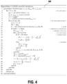
- FIG. 4 demonstrates a schematic illustration of example code 406 for simulating snowfall for a LiDAR system, as described previously.
- the code is a "pseudo code" in that the logic of the code may be implemented within any number of programming languages.
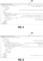
- FIG. 5 demonstrates a schematic illustration of example code 506 for snowflake sampling, such as to simulate the effect of snowfall on the LiDAR point cloud data by sampling snow particles in 2D space for each scanning layer of the LiDAR sensor.
- the code is a "pseudo code" in that the logic of the code may be implemented within any number of programming languages.
- FIG. 6 demonstrates a schematic illustration of example code 606 for computing LiDAR beam occlusions, such as by using induced geometry in order to compute for each LiDAR beam the set of particles that intersect with it and derive the angle of the beam cross-section that is reflected by each particle, taking occlusions into account in order to produce an impulse response of the linear system in the presence of snowfall that allows an analytical calculation of the received power at the receiver.
- the code is a "pseudo code" in that the logic of the code may be implemented within any number of programming languages.
- a partially synthetic snowy LiDAR data may be generated.
- FIG. 7 demonstrates the output of the process described.
- Camera Input a 3D representation of the input, which may be clear weather LiDAR data from a real world environment, is displayed.
- Algmented Output a 3D representation of the output, which may be the clear weather LiDAR data that has been augmented to add the simulated snowfall as previously described, is displayed.
- FIG. 8A shows a real world heavy snowfall scene. This may be a scene as viewed from a LiDAR system 103.
- FIG. 8B demonstrates the results of a conventional object detection model. As can be seen by comparing FIGS. 8A and 8B , the conventional object detection model is able to accurately detect objects from image, such as vehicle 804. However, it appears that due to interference from the snowfall, the object detection model has erroneously detected "ghost" objects 805 where this is clearly no object present.
- FIG. 8C represents the results of an object detection model that has been trained using as training dataset the partially synthetic snowy LiDAR data, such as that produced by the disclosed method. As can be seen, the object detection model in FIG. 8C is able to detect the "real" objects from FIG. 8A without erroneously detecting any ghost objects due to the effects of snowfall.
- the computer system may comprise various hardware components including one or more single or multi-core processors collectively represented by processor, a solid-state drive, a memory, which may be a random-access memory or any other type of memory. Communication between the various components of the computer system may be enabled by one or more internal and/or external buses (e.g. a PCI bus, universal serial bus, IEEE 1394 "Firewire" bus, SCSI bus, Serial-ATA bus, etc.), to which the various hardware components are electronically coupled.
- the drive may store program instructions suitable for being loaded into the memory and executed by the processor.
- the computer system may have additional and/or optional components, such as a network communication module for communication, via a communication network with other electronic devices and/or servers, localization modules, and the like.
- processor any functional block labeled as a "processor”
- the functions may be provided by a single dedicated processor, by a single shared processor, or by a plurality of individual processors, some of which may be shared.
- explicit use of the term "processor” or “controller” should not be construed to refer exclusively to hardware capable of executing software, and may implicitly include, without limitation, digital signal processor (DSP) hardware, network processor, application specific integrated circuit (ASIC), field programmable gate array (FPGA), read-only memory (ROM) for storing software, random access memory (RAM), and non-volatile storage.
- DSP digital signal processor
- ASIC application specific integrated circuit
- FPGA field programmable gate array
- ROM read-only memory
- RAM random access memory
- non-volatile storage Other hardware, conventional and/or custom, may also be included.
- FIG. 9 demonstrates a system 901 for generating a partially synthetic snowy LiDAR dataset.
- the system 901 may include a pulse emitter 902, a receiver 904, and a controller 907.
- the pulse emitter 902 and receiver 904 may be similar to those previously discussed.
- the pulse emitter 902, receiver 904, and controller 907 may not necessarily be located proximately or temporally close.
- the controller 907 may receive data from the receiver 904 and/or pulse emitter 902 that was collected at a different location and/or a different time.
- the pulse emitter 902, receiver 904, and controller 907 do not need to be directly connected or concurrently operation.
- the controller 907 may include a processing module 911 for obtaining the raw data from the receiver 904 and generating a LiDAR point cloud dataset. It is contemplated that the controller 904 may otherwise obtain the LiDAR point cloud dataset.
- the controller 907 may include a simulation module 914 configured to simulate the effect of snowfall on the LiDAR point cloud data, such as by the method outlined previously.
- the simulation module 914 may include a snowfall module.
- the snowfall module 917 may be configured to simulate the effects of snowfall on each LiDAR beam of the LiDAR point cloud data.
- the controller 907 may be configured to output the augmented LiDAR point cloud data as partially synthetic snowy LiDAR data.
- the controller 907 may include a training module 924 configured to use the partially synthetic snowy LiDAR data as a training dataset to train a 3D object detection model.
- a training module 924 configured to use the partially synthetic snowy LiDAR data as a training dataset to train a 3D object detection model.
- 3D object detection methods that may use the partially synthetic snowy LiDAR data as a training dataset are PV-RCNN, CenterPoint, Part-A 2 , PointRCNN, SECOND, PointPillars, and VoxelRCNN-Car.
- the controller may receive LiDAR data that has been collected by other means than described. Therefore, it is the object of the appended claims to cover all such variations and modifications as come within the true spirit and scope of the disclosure.
Landscapes
- Engineering & Computer Science (AREA)
- Physics & Mathematics (AREA)
- Computer Networks & Wireless Communication (AREA)
- General Physics & Mathematics (AREA)
- Radar, Positioning & Navigation (AREA)
- Remote Sensing (AREA)
- Electromagnetism (AREA)
- Optical Radar Systems And Details Thereof (AREA)
Abstract
-obtaining a LiDAR dataset containing LiDAR point cloud data for a clear weather environment that has been collected by a LiDAR system in a real environment (SI),
-simulating the effect of snowfall on the LiDAR point cloud data (S2), and
-augmenting the LiDAR point cloud data based on the simulated effect of snowfall to generate partially synthetic snowy LiDAR data (S5).
Description
- The present disclosure relates to the field of data simulation for 3D object detection.
- Autonomous vehicles and related systems utilize various computer-operated technologies for determining conditions around the vehicle. For instance, 3D object detection is a central task for applications such as autonomous driving, in which the system needs to localize and classify surrounding traffic agents. One technology commonly applied to this operation is LiDAR, which stands for Light Detection And Ranging. LiDAR uses lasers to create 3D representations of the surrounding environment by emitting pulsed light beams and capturing their reflection via receivers. These systems can be heavily impacted by adverse weather conditions due to the impact that precipitation and other environmental effects can have on the light beams. Further difficulties arise when attempting to collect and annotate training data in this type of setting.
- According to an aspect of the present disclosure, a computer-implemented method for simulating the effect of snowfall on LiDAR point clouds for a LiDAR system comprises obtaining a LiDAR dataset containing LiDAR point cloud data for a clear weather environment that has been collected by a LiDAR system in a real environment, simulating the effect of snowfall on the LiDAR point cloud data, and augmenting the LiDAR point cloud data based on the simulated effect of snowfall to generate partially synthetic snowy LiDAR data.
- Since adverse-weather data is difficult to collect, and thus adverse weather samples are rare and well underrepresented. This method allows for the generation of weather-based LiDAR data by simulating snowfall on real clear-weather LiDAR point clouds. This physically based simulation is realistic enough to relieve the need for real snowy training samples.
- In an example, the method further comprises utilizing the partially synthetic snow LiDAR data as training data for optimizing 3D object detection methods in order to train the 3D object detection methods to better discriminate between snow particles and target objects in a real environment.
- Object detection models trained using this method for generating training data with simulated snow may consistently achieve significant performance gains over baseline models trained only on clear weather and competing simulation methods.
- In an example, simulating the effect of snowfall on the LiDAR point cloud data comprises sampling snow particles in 2D space for each scanning layer of the LiDAR sensor.
- In an example, the snow particles are rendered as opaque spheres.
- In an example, the method further comprises selecting a snowfall rate, wherein said snowfall rate determines the size and amount of the snow particles. This allows data to be produced that simulates snowfall of varying intensity, such as light snowfall and heavy snowfall.
- In an example, the sampling is configured to obey the exclusion principle that no two snow particles intersect with each other.
- In an example, augmenting the LiDAR point cloud data comprises using induced geometry to modify an attribute for each LiDAR beam.
- In an example, using induced geometry comprises computing for each LiDAR beam the set of particles that intersect with it and derive the angle of the beam cross-section that is reflected by each particle, taking occlusions into account in order to produce an impulse response of the linear system in the presence of snowfall that allows an analytical calculation of the received power at the receiver.
- An aspect of the present disclosure is directed toward a training dataset configured to be used for optimizing 3D object detection methods, produced by the method disclosed.
- An aspect of the present disclosure is directed toward a system for generating a partially synthetic snowy LiDAR dataset, comprising one or more computer-readable media that store a program instruction and instruct a processor to carry out a method of obtaining a LiDAR dataset containing LiDAR point cloud data for a clear weather environment that has been collected by a LiDAR system in a real environment, simulating the effect of snowfall on the LiDAR point cloud data, and augmenting the LiDAR point cloud data based on the simulated effect of snowfall to generate partially synthetic snowy LiDAR data.
- In an example, the system further comprises a pulse emitter and a receiver, wherein the pulse emitter is configured to emit LiDAR beams and the receiver is configured to detect a reflected LiDAR beams.
- In an example, the controller is configured to generate a LiDAR dataset containing real LiDAR point cloud data for a clear weather environment based on attributes about the reflections of said LiDAR beam that are detected by the receiver.
- In an example, the system is configured to generate a LiDAR dataset containing real LiDAR point cloud data for a clear weather environment based on attributes of the reflections of the LiDAR beam.
- In an example, the system is configured to utilize the partially synthetic snow LiDAR data as training data for optimizing 3D object detection methods in order to train the 3D object detection methods to better discriminate between snow particles and target objects in a real environment.
- In an example, the system is configured to simulate the effect of snowfall on the LiDAR point cloud data comprises sampling snow particles in 2D space for each scanning layer of the LiDAR sensor.
- In an example, the system is configured to render the snow particles as opaque spheres.
- Other examples are provided herein.
- The disclosure may be more completely understood in consideration of the following detailed description of aspects of the disclosure in connection with the accompanying drawings, in which:
-
Fig. 1 shows an exemplary LiDAR system. -
Fig. 2 shows an exemplary method for producing a partially synthetic snow LiDAR data. -
Fig. 3A shows an exemplary LiDAR system operation with simulated snowfall. -
Fig. 3B shows an exemplary graph demonstrating reflected echoes of a LiDAR beam. -
Fig. 4 shows an exemplary code for producing aspects of a partially synthetic snow LiDAR data. -
Fig. 5 shows an exemplary code for snowflake sampling. -
Fig. 6 shows an exemplary code for computing LiDAR beam occlusions. -
Fig. 7 shows an exemplary input and output of a method for producing a partially synthetic snow LiDAR data. -
Figs. 8A-C show an exemplary snowy scene for the purposes of training a 3D object detection model. -
Fig. 9 shows a system for producing a partially synthetic snow LiDAR data. - The term "exemplary" is used in the sense of "example", rather than "ideal". While aspects of the disclosure are amenable to various modifications and alternative forms, specifics thereof have been shown by way of example in the drawings and will be described in detail. It should be understood, however, that the intention is not to limit aspects of the disclosure to the particular embodiment(s) described. On the contrary, the intention of this disclosure is to cover all modifications, equivalents, and alternatives falling within the scope of the disclosure.
- As used in this disclosure and the appended claims, the singular forms "a", "an", and "the" include plural referents unless the content clearly dictates otherwise. As used in this disclosure and the appended claims, the term "or" is generally employed in its sense including "and/or" unless the content clearly dictates otherwise.
- The following detailed description should be read with reference to the drawings. The detailed description and the drawings, which are not necessarily to scale, depict illustrative aspects and are not intended to limit the scope of the disclosure. The illustrative aspects depicted are intended only as exemplary.
- When an element or feature is referred to herein as being "on," "engaged to," "connected to," or "coupled to" another element or feature, it may be directly on, engaged, connected, or coupled to the other element or feature, or intervening elements or features may be present. In contrast, when an element or feature is referred to as being "directly on," "directly engaged to," "directly connected to," or "directly coupled to" another element or feature, there may be no intervening elements or features present. Other words used to describe the relationship between elements or features should be interpreted in a like fashion (for example, "between" versus "directly between," "adjacent" versus "directly adjacent," etc.).
- Although the terms "first," "second," etc. may be used herein to describe various elements, components, regions, layers, sections, and/or parameters, these elements, components, regions, layers, sections, and/or parameters should not be limited by these terms. These terms are only used to distinguish one element, component, region, layer, or section from another region, layer, or section. Thus, a first element, component, region, layer, or section discussed herein could be termed a second element, component, region, layer, or section without departing from the teachings of the present disclosure.
- The examples and conditional language recited herein are principally intended to aid the reader in understanding the principles of the present technology and not to limit its scope to such specifically recited examples and conditions. It will be appreciated that those skilled in the art may devise various arrangements which, although not explicitly described or shown herein, nonetheless embody the principles of the present technology and are included within its spirit and scope.
- Furthermore, as an aid to understanding, the following description may describe relatively simplified implementations of the present technology. As persons skilled in the art would understand, various implementations of the present technology may be of a greater complexity.
- In some cases, what are believed to be helpful examples of modifications to the present technology may also be set forth. This is done merely as an aid to understanding, and, again, not to define the scope or set forth the bounds of the present technology. These modifications are not an exhaustive list, and a person skilled in the art may make other modifications while nonetheless remaining within the scope of the present technology. Further, where no examples of modifications have been set forth, it should not be interpreted that no modifications are possible and/or that what is described is the sole manner of implementing that element of the present technology.
- Moreover, all statements herein reciting principles, aspects, and implementations of the technology, as well as specific examples thereof, are intended to encompass both structural and functional equivalents thereof, whether they are currently known or developed in the future. Thus, for example, it will be appreciated by those skilled in the art that any block diagrams herein represent conceptual views of illustrative circuitry embodying the principles of the present technology. Similarly, it will be appreciated that any flowcharts, flow diagrams, state transition diagrams, pseudo-code, and the like represent various processes which may be substantially represented in computer-readable media and so executed by a computer or processor, whether or not such computer or processor is explicitly shown.
- With these fundamentals in place, we will now consider some non-limiting examples to illustrate various implementations of aspects of the present technology.
- A
LiDAR system 103, such as the one shown inFIG. 1 , may include a pulse emitter Tx and a receiver Rx. The pulse emitter Tx may include one or more light sources for transmitting light or photon beams. Examples of suitable light sources include lasers, laser diodes, light emitting diodes, organic light emitting diodes, or the like. For instance, the pulse emitter may include one or more visible and/or non-visible laser sources. In at least some embodiment, light source includes one or more non-visible laser sources, such as a near-infrared (NIR), short-wave infrared (SWIR), mid-wave infrared (MWIR), long-wave infrared (LWIR) laser, or the like. A light source may provide continuous or pulsed light beams of a predetermined frequency, or range of frequencies. The provided light beams may be coherent light beams. In an example, the pulse emitters Tx may be an array synchronized near field infrared pulse emitters. - The receivers Rx may include one or more photon-sensitive, or photondetecting, arrays of sensor pixels. An array of sensor pixels may be configured to detect continuous or pulsed light beams on a constant or sporadic basis. The array of pixels may be a one dimensional-array or a two-dimensional array. The pixels may include single photon avalanche diodes (SPADs) or other photo-sensitive elements that avalanche upon the illumination of one or a few incoming photons. The pixels may have ultra-fast response times in detecting a single or a few photons that are on the order of a few nanoseconds. The pixels may be sensitive to the frequencies emitted or transmitted by pulse emitter Tx and relatively insensitive to other frequencies. In an example, the receivers Rx may be avalanche photodiodes (APDs).
- During operation of the
LiDAR system 103, the pulse emitters Tx may emit a LiDAR beam with power P0. The LiDAR beam is reflected by a solid scene object, often referred to as target, that has a reflectivity ρ0. The LiDAR beam may be captured by the receiver Rx. Attributes of the recovered LiDAR beam may be detected by the receiver Rx, such as the time delay τ of the captured echo and its corresponding power PR. The object distance R of the target may be calculated by applying R = cτ , where c is the speed of light. A 3D position [x, y, z] of the target relative to theLiDAR system 103 may be further determined from this information, such as by using the direction in which the LiDAR beam with power P0 was emitted in coordination with the object distance R. - By collating a dataset of bounced LiDAR beams, wherein each bounced LiDAR beam represents a target data point, a LiDAR point cloud may be produced that is embodies a virtual representation of the surroundings of the
LiDAR system 103. An increase in the number of points within the LiDAR point cloud may represent an increase of the fidelity between the representation and the "real-world" surroundings of theLiDAR system 103. This fidelity is also affected by the medium that the LiDAR beams pass through. For instance, the presence of scattering particles, such as snow, rain, fog, etc., may decrease the fidelity of the LiDAR point cloud. Therefore, theLiDAR system 103 may optimally produce a LiDAR point cloud dataset for a clear weather environment. - A process for producing a linear model for pulse propagation in the presence of scattering particles, such as the process shown in
FIG. 2 , may be described. - In step S1, a LiDAR point cloud dataset may be obtained. The LiDAR point cloud dataset may represent a LiDAR dataset containing LiDAR point cloud data for a clear weather environment that has been collected by a
LiDAR system 103 in a real environment. For example, the LiDAR point cloud dataset may be a dataset collected by theLiDAR system 103 previously described for a clear weather environment in the real world. - In step S2, the snowfall effect on the LiDAR point cloud data may be simulated. This may include step S3, in which a sample of snow particles in a given space may be produced. The snow particles may be sampled in 2D space for each LiDAR beam of the dataset. Snowfall may be simulated that is based on a sampling of snow particles. The sampled snow particles may be modeled as spheres, and more specifically as opaque spheres. The size of the spheres may be correlated to a snowfall rate, and therefore a snowfall rate may be selected, wherein said snowfall rate determines the size and amount of the snow particles. The model may further obey the exclusion principle such that no two snow particles may intersect with each other. Thus, the sample of snow particles may be produced.
- In step S4, an attribute for each LiDAR beam that is impacted by a snow particle may be modified, such as by using induced geometry.
- In step S5, a partially synthetic snowy LiDAR data may be generated, such as by augmenting the LiDAR point cloud data based on the simulated effect of snowfall. This may also include collating the LiDAR beam data that was previously modified. The collated LiDAR beam data may constitute a "training dataset."
- In step S6, the generated partially synthetic point clouds that include snowfall simulation effects may be used as training data for optimizing 3D object detection methods in order to train the 3D object detection methods to better discriminate between snow particles and target objects in a real environment.
- Further aspects of this method and may be described herein.
- As discussed previously, a LiDAR point cloud dataset may include attributes of the recovered LiDAR beam that may be detected by the receiver Rx, such as the time delay τ of the captured echo and its corresponding power PR. For extended objects, geometric optics can be applied to model the received power PR by using the formulation:

which holds for objects with a diameter larger than the beam diameter of the LiDAR beam with power P0 at distance R and. Additional information may be needed, namely (i) the incident angle αin and (ii) the system constant CA independent of range and time. Because the system constant CA may differ for each scanning layer due to different optics and beam divergences, a correction coefficient is typically applied to the received power PR that corresponds with the specific hardware that is used due to differences in optics and beam divergence. - Thus, pulse propagation in "free space", i.e., lacking scattering particles, may be modeled based on the discussed principles of geometrical optics in order to model the transmission of the LiDAR beams with power P0 and the associated received power PR at the
LiDAR system 103. - In order to prepare the LiDAR data for processing, the intensity calibration of the sensor may be inverted to obtain the raw intensity data. In snowfall, the optical medium contains particles which are smaller than the beam diameter, so Mie scattering and the exact spatial distribution of the particles are taken into account.
- For each LiDAR beam, the set of snow particles that intersect with it may be computed, such as to derive the angle of the LiDAR beam cross-section that is reflected by each snow particle while taking potential occlusions into account.
- Pulse propagation in the presence of scattering particles may be determined, such as by determining the modified impulse response of the linear system in the presence of snowfall, which allows the analytical calculation of the received power PR at the sensor. The range-dependent received power PR may be expressed as a time-wise convolution between the time-dependent transmitted signal power PT and the impulse response H of the optical system:

with the time signature of the transmitted pulse given by:


- HC depends on the beam divergence, the overlap of transmitter and receiver described by ξ(R) as well as the transmittance T(R) of the medium through:

- The transmittance T(R) is equal to 1 in the part of the medium that is not occupied by snow particles. The absence of further "scattering elements" may be assumed. The overlap ξ(R) may be geometrically derived from the physical attributes of the LiDAR system, such as that shown in
FIG. 1 , as

- The impulse response of the target, HT, enables the modelling of the model snow particles.
- "Scene reflection" defines a particle interaction with the laser pulse by means of the impulse response HT. For an extended solid target object, the following equation may be used:

with ρ0 being the reflectivity of the object and δ the Dirac delta function. In snowfall, the laser beam is partially reflected by snow particles in addition to the solid target object. -
FIG. 3A shows a representation of the snow particles j relative to aLiDAR sensor 301. A snow particle j may be modeled as a spherical object with a reflectivity ρs, a diameter Dj that is based upon a given distribution such that the snow particle j has an azimuth angle and distance Rj relative the sensor. Each of the snow particles j may be placed, such as uniformly and/or at random, around the sensor. Each of the snow particles j may be placed so that no snow particle j "intersects," or shares physical space, with any other snow particle j or thesensor 301 itself. The number of snow particles that are placed may be determined by a desired snowfall rate, which may be generated, detected, or otherwise determined. For instance, a typical snowfall rate may include a range of 0-2.5 mm/h, although a higher rate is considered. - A representation of a
single LiDAR beam 304 can be seen. The individual snow particles j may partially or fully block the path of the LiDAR beam j between thesensor 301 and the target object. Additionally, the individual snow particles j may partially or fully block the LiDAR beam with respect to each other. Thus, each particle j reflects only a fraction θj/Θ of the opening angle Θ of the beam, also letting a fraction θ0/Θ of the beam reach the target. - Assuming Dj << cτH for all particles j, the following equation may be used:

with
- When the results of
Equation 3,Equation 4,Equation 5, andEquation 8 are entered intoEquation 2, the received power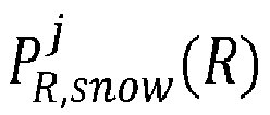


Equation 10. - The received power PR is thus a superposition of
multiple echoes 308, wherein eachecho 308 is each associated with an object, such as a snow particle j or target object, as depicted inFIG. 3B . The magnitude of eachecho 308 may depend on the azimuth angle θj and the inverse square of the distance Rj of the respective object from thesensor 301. The maximum peak of the received power may be taken to be theLiDAR beam 304 return. Thus, if a peak that is present due to a snow particle j is higher than a peak associated with the target object, thetrue echo 308 is missed and a cluttered point is added to the simulated point cloud at the range of peak of the snow particle j. Otherwise, the target object intensity is attenuated according to its occlusion percentage. -
FIG. 4 demonstrates a schematic illustration ofexample code 406 for simulating snowfall for a LiDAR system, as described previously. The code is a "pseudo code" in that the logic of the code may be implemented within any number of programming languages. -
FIG. 5 demonstrates a schematic illustration ofexample code 506 for snowflake sampling, such as to simulate the effect of snowfall on the LiDAR point cloud data by sampling snow particles in 2D space for each scanning layer of the LiDAR sensor. The code is a "pseudo code" in that the logic of the code may be implemented within any number of programming languages. -
FIG. 6 demonstrates a schematic illustration ofexample code 606 for computing LiDAR beam occlusions, such as by using induced geometry in order to compute for each LiDAR beam the set of particles that intersect with it and derive the angle of the beam cross-section that is reflected by each particle, taking occlusions into account in order to produce an impulse response of the linear system in the presence of snowfall that allows an analytical calculation of the received power at the receiver. The code is a "pseudo code" in that the logic of the code may be implemented within any number of programming languages. - Using the method previously described, a partially synthetic snowy LiDAR data may be generated.
-
FIG. 7 demonstrates the output of the process described. In the drawing labeled "Clear Input," a 3D representation of the input, which may be clear weather LiDAR data from a real world environment, is displayed. In the drawing labeled "Augmented Output," a 3D representation of the output, which may be the clear weather LiDAR data that has been augmented to add the simulated snowfall as previously described, is displayed. -
FIG. 8A shows a real world heavy snowfall scene. This may be a scene as viewed from aLiDAR system 103.FIG. 8B demonstrates the results of a conventional object detection model. As can be seen by comparingFIGS. 8A and 8B , the conventional object detection model is able to accurately detect objects from image, such asvehicle 804. However, it appears that due to interference from the snowfall, the object detection model has erroneously detected "ghost" objects 805 where this is clearly no object present.FIG. 8C represents the results of an object detection model that has been trained using as training dataset the partially synthetic snowy LiDAR data, such as that produced by the disclosed method. As can be seen, the object detection model inFIG. 8C is able to detect the "real" objects fromFIG. 8A without erroneously detecting any ghost objects due to the effects of snowfall. - Aspects of the present disclosure may be implemented by or incorporate elements of a computer system. The computer system may comprise various hardware components including one or more single or multi-core processors collectively represented by processor, a solid-state drive, a memory, which may be a random-access memory or any other type of memory. Communication between the various components of the computer system may be enabled by one or more internal and/or external buses (e.g. a PCI bus, universal serial bus, IEEE 1394 "Firewire" bus, SCSI bus, Serial-ATA bus, etc.), to which the various hardware components are electronically coupled. The drive may store program instructions suitable for being loaded into the memory and executed by the processor. It is noted that the computer system may have additional and/or optional components, such as a network communication module for communication, via a communication network with other electronic devices and/or servers, localization modules, and the like.
- The functions of the various computer elements, including any functional block labeled as a "processor", may be provided through the use of dedicated hardware as well as hardware capable of executing software in association with appropriate software. When provided by a processor, the functions may be provided by a single dedicated processor, by a single shared processor, or by a plurality of individual processors, some of which may be shared. Moreover, explicit use of the term "processor" or "controller" should not be construed to refer exclusively to hardware capable of executing software, and may implicitly include, without limitation, digital signal processor (DSP) hardware, network processor, application specific integrated circuit (ASIC), field programmable gate array (FPGA), read-only memory (ROM) for storing software, random access memory (RAM), and non-volatile storage. Other hardware, conventional and/or custom, may also be included.
- Software modules, or simply modules which are implied to be software, may be represented herein as any combination of flowchart elements or other elements indicating performance of process steps and/or textual description. Such modules may be executed by hardware that is expressly or implicitly shown.
-
FIG. 9 demonstrates asystem 901 for generating a partially synthetic snowy LiDAR dataset. Thesystem 901 may include apulse emitter 902, areceiver 904, and acontroller 907. Thepulse emitter 902 andreceiver 904 may be similar to those previously discussed. Thepulse emitter 902,receiver 904, andcontroller 907 may not necessarily be located proximately or temporally close. For instance, thecontroller 907 may receive data from thereceiver 904 and/orpulse emitter 902 that was collected at a different location and/or a different time. Thus, thepulse emitter 902,receiver 904, andcontroller 907 do not need to be directly connected or concurrently operation. - The
controller 907 may include aprocessing module 911 for obtaining the raw data from thereceiver 904 and generating a LiDAR point cloud dataset. It is contemplated that thecontroller 904 may otherwise obtain the LiDAR point cloud dataset. - The
controller 907 may include asimulation module 914 configured to simulate the effect of snowfall on the LiDAR point cloud data, such as by the method outlined previously. Thesimulation module 914 may include a snowfall module. Thesnowfall module 917 may be configured to simulate the effects of snowfall on each LiDAR beam of the LiDAR point cloud data. Thecontroller 907 may be configured to output the augmented LiDAR point cloud data as partially synthetic snowy LiDAR data. - The
controller 907 may include atraining module 924 configured to use the partially synthetic snowy LiDAR data as a training dataset to train a 3D object detection model. Non-limiting examples of 3D object detection methods that may use the partially synthetic snowy LiDAR data as a training dataset are PV-RCNN, CenterPoint, Part-A2, PointRCNN, SECOND, PointPillars, and VoxelRCNN-Car. - The foregoing description has been directed to specific embodiments of the present disclosure. It will be apparent, however, that other variations and modifications may be made to the described embodiments, with the attainment of some or all of their advantages. For example, the controller may receive LiDAR data that has been collected by other means than described. Therefore, it is the object of the appended claims to cover all such variations and modifications as come within the true spirit and scope of the disclosure.
Claims (15)
- A computer-implemented method for simulating the effect of snowfall on LiDAR point clouds for a LiDAR system comprising:- obtaining a LiDAR dataset containing LiDAR point cloud data for a clear weather environment that has been collected by a LiDAR system in a real environment (S1),- simulating the effect of snowfall on the LiDAR point cloud data (S2), and- augmenting the LiDAR point cloud data based on the simulated effect of snowfall to generate partially synthetic snowy LiDAR data (S5).
- The computer-implemented method of claim 1, further comprising utilizing the partially synthetic snow LiDAR data as training data for optimizing 3D object detection methods in order to train the 3D object detection methods to better discriminate between snow particles and target objects in a real environment (S6).
- The computer-implemented method of any of claims 1 or 2, wherein simulating the effect of snowfall on the LiDAR point cloud data comprises sampling snow particles in 2D space for each LiDAR beam of the dataset (S3).
- The computer-implemented method of claim 3, wherein the snow particles are rendered as opaque spheres.
- The computer-implemented method of any of claims 3 or 4, furthering comprising selecting a snowfall rate, wherein said snowfall rate determines the size and amount of the snow particles.
- The computer-implemented method of any of claims 3 to 5, wherein the sampling is configured to obey the exclusion principle that no two snow particles intersect with each other.
- The computer-implemented method of any of claims 3 to 6, wherein augmenting the LiDAR point cloud data comprises using induced geometry to modify an attribute for each LiDAR beam (S4).
- The computer-implemented method of claim 7, wherein using induced geometry comprises computing for each LiDAR beam the set of particles that intersect with it and derive the angle of the beam cross-section that is reflected by each particle, taking occlusions into account in order to produce an impulse response of the linear system in the presence of snowfall that allows an analytical calculation of the received power at the receiver.
- A training dataset configured to be used for optimizing 3D object detection methods, produced by the method of any of claims 1 to 8.
- A system (901) for generating a partially synthetic snowy LiDAR dataset, comprising one or more computer-readable media that store a program instruction and instruct a controller (907) to carry out a method of- obtaining a LiDAR dataset containing LiDAR point cloud data for a clear weather environment that has been collected by a LiDAR system in a real environment,- simulating the effect of snowfall on the LiDAR point cloud data, and- augmenting the LiDAR point cloud data based on the simulated effect of snowfall to generate partially synthetic snowy LiDAR data.
- The system (901) of claim 10, further comprising a pulse emitter (902) and a receiver (904), wherein the pulse emitter (902) is configured to emit a LiDAR beam and the receiver (904) is configured to detect a reflected LiDAR beam.
- The system (901) of claim 10, further comprising that the controller (907) is configured to generate a LiDAR dataset containing real LiDAR point cloud data for a clear weather environment based on attributes of the reflections of the LiDAR beam.
- The system (901) of claim 11, further comprising that the system (901) is configured to utilize the partially synthetic snow LiDAR data as training data for optimizing 3D object detection methods in order to train the 3D object detection methods to better discriminate between snow particles and target objects in a real environment.
- The system (901) of any of claims 11 to 13, wherein simulating the effect of snowfall on the LiDAR point cloud data comprises sampling snow particles in 2D space for each LiDAR beam of the dataset.
- The system (901) of claim 14, wherein the snow particles are rendered as opaque spheres.
Priority Applications (1)
| Application Number | Priority Date | Filing Date | Title |
|---|---|---|---|
| EP22158998.9A EP4235214B1 (en) | 2022-02-25 | 2022-02-25 | Lidar snowfall simulation method and system for robust 3d object detection |
Applications Claiming Priority (1)
| Application Number | Priority Date | Filing Date | Title |
|---|---|---|---|
| EP22158998.9A EP4235214B1 (en) | 2022-02-25 | 2022-02-25 | Lidar snowfall simulation method and system for robust 3d object detection |
Publications (2)
| Publication Number | Publication Date |
|---|---|
| EP4235214A1 true EP4235214A1 (en) | 2023-08-30 |
| EP4235214B1 EP4235214B1 (en) | 2025-05-21 |
Family
ID=80628628
Family Applications (1)
| Application Number | Title | Priority Date | Filing Date |
|---|---|---|---|
| EP22158998.9A Active EP4235214B1 (en) | 2022-02-25 | 2022-02-25 | Lidar snowfall simulation method and system for robust 3d object detection |
Country Status (1)
| Country | Link |
|---|---|
| EP (1) | EP4235214B1 (en) |
Cited By (1)
| Publication number | Priority date | Publication date | Assignee | Title |
|---|---|---|---|---|
| WO2025173362A1 (en) * | 2024-02-13 | 2025-08-21 | キヤノン株式会社 | Encoding device, decoding device, storage medium, and computer program |
Citations (3)
| Publication number | Priority date | Publication date | Assignee | Title |
|---|---|---|---|---|
| US20180275658A1 (en) * | 2017-03-23 | 2018-09-27 | DeepScale, Inc. | Data synthesis for autonomous control systems |
| CN112163280A (en) * | 2020-10-28 | 2021-01-01 | 腾讯科技(深圳)有限公司 | Method, device and equipment for simulating automatic driving scene and storage medium |
| US20210339738A1 (en) * | 2020-04-29 | 2021-11-04 | GM Global Technology Operations LLC | Method and system for operating an on-vehicle lidar sensor |
-
2022
- 2022-02-25 EP EP22158998.9A patent/EP4235214B1/en active Active
Patent Citations (3)
| Publication number | Priority date | Publication date | Assignee | Title |
|---|---|---|---|---|
| US20180275658A1 (en) * | 2017-03-23 | 2018-09-27 | DeepScale, Inc. | Data synthesis for autonomous control systems |
| US20210339738A1 (en) * | 2020-04-29 | 2021-11-04 | GM Global Technology Operations LLC | Method and system for operating an on-vehicle lidar sensor |
| CN112163280A (en) * | 2020-10-28 | 2021-01-01 | 腾讯科技(深圳)有限公司 | Method, device and equipment for simulating automatic driving scene and storage medium |
Non-Patent Citations (2)
| Title |
|---|
| CARRILLO JUSTIN ET AL: "Using Physics-Based M&S for Training and Testing Machine Learning Algorithms", 14 March 2019, ADVANCES IN DATABASES AND INFORMATION SYSTEMS; [LECTURE NOTES IN COMPUTER SCIENCE; LECT.NOTES COMPUTER], SPRINGER INTERNATIONAL PUBLISHING, CHAM, PAGE(S) 445 - 455, ISBN: 978-3-319-10403-4, XP047504560 * |
| KILIC VELAT ET AL: "Lidar Light Scattering Augmentation (LISA): Physics-based Simulation of Adverse Weather Conditions for 3D Object Detection", 14 July 2021 (2021-07-14), XP055946616, Retrieved from the Internet <URL:https://arxiv.org/abs/2107.07004> [retrieved on 20220727] * |
Cited By (1)
| Publication number | Priority date | Publication date | Assignee | Title |
|---|---|---|---|---|
| WO2025173362A1 (en) * | 2024-02-13 | 2025-08-21 | キヤノン株式会社 | Encoding device, decoding device, storage medium, and computer program |
Also Published As
| Publication number | Publication date |
|---|---|
| EP4235214B1 (en) | 2025-05-21 |
Similar Documents
| Publication | Publication Date | Title |
|---|---|---|
| Hahner et al. | Lidar snowfall simulation for robust 3d object detection | |
| Rapp et al. | Advances in single-photon lidar for autonomous vehicles: Working principles, challenges, and recent advances | |
| US20240346816A1 (en) | Data synthesis for autonomous control systems | |
| US10641900B2 (en) | Low latency intra-frame motion estimation based on clusters of ladar pulses | |
| US10592805B2 (en) | Physics modeling for radar and ultrasonic sensors | |
| US8655513B2 (en) | Methods of real time image enhancement of flash LIDAR data and navigating a vehicle using flash LIDAR data | |
| Hasirlioglu et al. | Reproducible fog simulation for testing automotive surround sensors | |
| Zhou | A review of LiDAR sensor technologies for perception in automated driving | |
| US20120033196A1 (en) | Method for Enhancing a Three Dimensional Image from a Plurality of Frames of Flash Lidar Data | |
| GB2573635A (en) | Object detection system and method | |
| Rosenberger et al. | Analysis of real world sensor behavior for rising fidelity of physically based lidar sensor models | |
| WO2023083198A1 (en) | Echo signal processing method and apparatus, device, and storage medium | |
| US20240418860A1 (en) | METHOD AND SYSTEM FOR VALIDATING END-TO-END LiDAR SENSING AND DIGITAL SIGNAL PROCESSOR OPTIMIZATION FOR 3D OBJECT DETECTION AND DEPTH ESTIMATION | |
| EP4235214A1 (en) | Lidar snowfall simulation method and system for robust 3d object detection | |
| CN112560258A (en) | Test method, device, equipment and storage medium | |
| Agarwal et al. | A monocular camera depth estimate approximation using deep learning | |
| CN119323141A (en) | Foggy scene generation method and system for automatic driving simulation test | |
| US20240175709A1 (en) | Method and electronic device for controlling operation of a self driving car | |
| EP4124888B1 (en) | A method for processing a lidar point cloud to simulate the presence of an aerosol such as fog | |
| Al-Temeemy | The development of a 3D LADAR simulator based on a fast target impulse response generation approach | |
| Riviere et al. | 3D LiDAR performance analysis for tactical-mapping applications | |
| US12596175B2 (en) | Non-resolved target detection system and methods | |
| CN118070571B (en) | Simulation method, device and storage medium of laser sensor | |
| CN115902865B (en) | Modified ray tracker for electromagnetic response simulator | |
| Rajender | Designing of Synthetic Aperture Radar Based Control Algorithms for the Autonomous Vehicles |
Legal Events
| Date | Code | Title | Description |
|---|---|---|---|
| PUAI | Public reference made under article 153(3) epc to a published international application that has entered the european phase |
Free format text: ORIGINAL CODE: 0009012 |
|
| STAA | Information on the status of an ep patent application or granted ep patent |
Free format text: STATUS: REQUEST FOR EXAMINATION WAS MADE |
|
| 17P | Request for examination filed |
Effective date: 20220225 |
|
| AK | Designated contracting states |
Kind code of ref document: A1 Designated state(s): AL AT BE BG CH CY CZ DE DK EE ES FI FR GB GR HR HU IE IS IT LI LT LU LV MC MK MT NL NO PL PT RO RS SE SI SK SM TR |
|
| GRAP | Despatch of communication of intention to grant a patent |
Free format text: ORIGINAL CODE: EPIDOSNIGR1 |
|
| STAA | Information on the status of an ep patent application or granted ep patent |
Free format text: STATUS: GRANT OF PATENT IS INTENDED |
|
| RIC1 | Information provided on ipc code assigned before grant |
Ipc: G01S 17/89 20200101ALI20241122BHEP Ipc: G01S 7/497 20060101AFI20241122BHEP |
|
| INTG | Intention to grant announced |
Effective date: 20241223 |
|
| GRAS | Grant fee paid |
Free format text: ORIGINAL CODE: EPIDOSNIGR3 |
|
| GRAA | (expected) grant |
Free format text: ORIGINAL CODE: 0009210 |
|
| STAA | Information on the status of an ep patent application or granted ep patent |
Free format text: STATUS: THE PATENT HAS BEEN GRANTED |
|
| AK | Designated contracting states |
Kind code of ref document: B1 Designated state(s): AL AT BE BG CH CY CZ DE DK EE ES FI FR GB GR HR HU IE IS IT LI LT LU LV MC MK MT NL NO PL PT RO RS SE SI SK SM TR |
|
| REG | Reference to a national code |
Ref country code: GB Ref legal event code: FG4D |
|
| REG | Reference to a national code |
Ref country code: CH Ref legal event code: EP |
|
| REG | Reference to a national code |
Ref country code: DE Ref legal event code: R096 Ref document number: 602022014816 Country of ref document: DE |
|
| REG | Reference to a national code |
Ref country code: IE Ref legal event code: FG4D |
|
| REG | Reference to a national code |
Ref country code: NL Ref legal event code: MP Effective date: 20250521 |
|
| PG25 | Lapsed in a contracting state [announced via postgrant information from national office to epo] |
Ref country code: ES Free format text: LAPSE BECAUSE OF FAILURE TO SUBMIT A TRANSLATION OF THE DESCRIPTION OR TO PAY THE FEE WITHIN THE PRESCRIBED TIME-LIMIT Effective date: 20250521 Ref country code: FI Free format text: LAPSE BECAUSE OF FAILURE TO SUBMIT A TRANSLATION OF THE DESCRIPTION OR TO PAY THE FEE WITHIN THE PRESCRIBED TIME-LIMIT Effective date: 20250521 Ref country code: PT Free format text: LAPSE BECAUSE OF FAILURE TO SUBMIT A TRANSLATION OF THE DESCRIPTION OR TO PAY THE FEE WITHIN THE PRESCRIBED TIME-LIMIT Effective date: 20250922 |
|
| REG | Reference to a national code |
Ref country code: LT Ref legal event code: MG9D |
|
| PG25 | Lapsed in a contracting state [announced via postgrant information from national office to epo] |
Ref country code: GR Free format text: LAPSE BECAUSE OF FAILURE TO SUBMIT A TRANSLATION OF THE DESCRIPTION OR TO PAY THE FEE WITHIN THE PRESCRIBED TIME-LIMIT Effective date: 20250822 Ref country code: NO Free format text: LAPSE BECAUSE OF FAILURE TO SUBMIT A TRANSLATION OF THE DESCRIPTION OR TO PAY THE FEE WITHIN THE PRESCRIBED TIME-LIMIT Effective date: 20250821 |
|
| PG25 | Lapsed in a contracting state [announced via postgrant information from national office to epo] |
Ref country code: NL Free format text: LAPSE BECAUSE OF FAILURE TO SUBMIT A TRANSLATION OF THE DESCRIPTION OR TO PAY THE FEE WITHIN THE PRESCRIBED TIME-LIMIT Effective date: 20250521 Ref country code: PL Free format text: LAPSE BECAUSE OF FAILURE TO SUBMIT A TRANSLATION OF THE DESCRIPTION OR TO PAY THE FEE WITHIN THE PRESCRIBED TIME-LIMIT Effective date: 20250521 |
|
| PG25 | Lapsed in a contracting state [announced via postgrant information from national office to epo] |
Ref country code: BG Free format text: LAPSE BECAUSE OF FAILURE TO SUBMIT A TRANSLATION OF THE DESCRIPTION OR TO PAY THE FEE WITHIN THE PRESCRIBED TIME-LIMIT Effective date: 20250521 |
|
| PG25 | Lapsed in a contracting state [announced via postgrant information from national office to epo] |
Ref country code: HR Free format text: LAPSE BECAUSE OF FAILURE TO SUBMIT A TRANSLATION OF THE DESCRIPTION OR TO PAY THE FEE WITHIN THE PRESCRIBED TIME-LIMIT Effective date: 20250521 |
|
| PG25 | Lapsed in a contracting state [announced via postgrant information from national office to epo] |
Ref country code: RS Free format text: LAPSE BECAUSE OF FAILURE TO SUBMIT A TRANSLATION OF THE DESCRIPTION OR TO PAY THE FEE WITHIN THE PRESCRIBED TIME-LIMIT Effective date: 20250821 |
|
| PG25 | Lapsed in a contracting state [announced via postgrant information from national office to epo] |
Ref country code: IS Free format text: LAPSE BECAUSE OF FAILURE TO SUBMIT A TRANSLATION OF THE DESCRIPTION OR TO PAY THE FEE WITHIN THE PRESCRIBED TIME-LIMIT Effective date: 20250921 |
|
| PG25 | Lapsed in a contracting state [announced via postgrant information from national office to epo] |
Ref country code: LV Free format text: LAPSE BECAUSE OF FAILURE TO SUBMIT A TRANSLATION OF THE DESCRIPTION OR TO PAY THE FEE WITHIN THE PRESCRIBED TIME-LIMIT Effective date: 20250521 |
|
| REG | Reference to a national code |
Ref country code: AT Ref legal event code: MK05 Ref document number: 1797198 Country of ref document: AT Kind code of ref document: T Effective date: 20250521 |
|
| PG25 | Lapsed in a contracting state [announced via postgrant information from national office to epo] |
Ref country code: DK Free format text: LAPSE BECAUSE OF FAILURE TO SUBMIT A TRANSLATION OF THE DESCRIPTION OR TO PAY THE FEE WITHIN THE PRESCRIBED TIME-LIMIT Effective date: 20250521 Ref country code: AT Free format text: LAPSE BECAUSE OF FAILURE TO SUBMIT A TRANSLATION OF THE DESCRIPTION OR TO PAY THE FEE WITHIN THE PRESCRIBED TIME-LIMIT Effective date: 20250521 Ref country code: SM Free format text: LAPSE BECAUSE OF FAILURE TO SUBMIT A TRANSLATION OF THE DESCRIPTION OR TO PAY THE FEE WITHIN THE PRESCRIBED TIME-LIMIT Effective date: 20250521 |
|
| PG25 | Lapsed in a contracting state [announced via postgrant information from national office to epo] |
Ref country code: CZ Free format text: LAPSE BECAUSE OF FAILURE TO SUBMIT A TRANSLATION OF THE DESCRIPTION OR TO PAY THE FEE WITHIN THE PRESCRIBED TIME-LIMIT Effective date: 20250521 |
|
| PG25 | Lapsed in a contracting state [announced via postgrant information from national office to epo] |
Ref country code: EE Free format text: LAPSE BECAUSE OF FAILURE TO SUBMIT A TRANSLATION OF THE DESCRIPTION OR TO PAY THE FEE WITHIN THE PRESCRIBED TIME-LIMIT Effective date: 20250521 |
|
| PG25 | Lapsed in a contracting state [announced via postgrant information from national office to epo] |
Ref country code: SK Free format text: LAPSE BECAUSE OF FAILURE TO SUBMIT A TRANSLATION OF THE DESCRIPTION OR TO PAY THE FEE WITHIN THE PRESCRIBED TIME-LIMIT Effective date: 20250521 |
|
| PG25 | Lapsed in a contracting state [announced via postgrant information from national office to epo] |
Ref country code: IT Free format text: LAPSE BECAUSE OF FAILURE TO SUBMIT A TRANSLATION OF THE DESCRIPTION OR TO PAY THE FEE WITHIN THE PRESCRIBED TIME-LIMIT Effective date: 20250521 |
|
| REG | Reference to a national code |
Ref country code: DE Ref legal event code: R097 Ref document number: 602022014816 Country of ref document: DE |
|
| PLBE | No opposition filed within time limit |
Free format text: ORIGINAL CODE: 0009261 |
|
| STAA | Information on the status of an ep patent application or granted ep patent |
Free format text: STATUS: NO OPPOSITION FILED WITHIN TIME LIMIT |
|
| REG | Reference to a national code |
Ref country code: CH Ref legal event code: L10 Free format text: ST27 STATUS EVENT CODE: U-0-0-L10-L00 (AS PROVIDED BY THE NATIONAL OFFICE) Effective date: 20260402 |
|
| PGFP | Annual fee paid to national office [announced via postgrant information from national office to epo] |
Ref country code: DE Payment date: 20260102 Year of fee payment: 5 |
|
| 26N | No opposition filed |
Effective date: 20260224 |