EP4235021A2 - Light source unit, and light emitting device for mobile body - Google Patents
Light source unit, and light emitting device for mobile body Download PDFInfo
- Publication number
- EP4235021A2 EP4235021A2 EP23178902.5A EP23178902A EP4235021A2 EP 4235021 A2 EP4235021 A2 EP 4235021A2 EP 23178902 A EP23178902 A EP 23178902A EP 4235021 A2 EP4235021 A2 EP 4235021A2
- Authority
- EP
- European Patent Office
- Prior art keywords
- light
- light emitting
- light source
- emitting layer
- source unit
- Prior art date
- Legal status (The legal status is an assumption and is not a legal conclusion. Google has not performed a legal analysis and makes no representation as to the accuracy of the status listed.)
- Pending
Links
Images



Classifications
-
- F—MECHANICAL ENGINEERING; LIGHTING; HEATING; WEAPONS; BLASTING
- F21—LIGHTING
- F21S—NON-PORTABLE LIGHTING DEVICES; SYSTEMS THEREOF; VEHICLE LIGHTING DEVICES SPECIALLY ADAPTED FOR VEHICLE EXTERIORS
- F21S43/00—Signalling devices specially adapted for vehicle exteriors, e.g. brake lamps, direction indicator lights or reversing lights
- F21S43/20—Signalling devices specially adapted for vehicle exteriors, e.g. brake lamps, direction indicator lights or reversing lights characterised by refractors, transparent cover plates, light guides or filters
- F21S43/235—Light guides
- F21S43/236—Light guides characterised by the shape of the light guide
- F21S43/239—Light guides characterised by the shape of the light guide plate-shaped
-
- F—MECHANICAL ENGINEERING; LIGHTING; HEATING; WEAPONS; BLASTING
- F21—LIGHTING
- F21S—NON-PORTABLE LIGHTING DEVICES; SYSTEMS THEREOF; VEHICLE LIGHTING DEVICES SPECIALLY ADAPTED FOR VEHICLE EXTERIORS
- F21S43/00—Signalling devices specially adapted for vehicle exteriors, e.g. brake lamps, direction indicator lights or reversing lights
- F21S43/20—Signalling devices specially adapted for vehicle exteriors, e.g. brake lamps, direction indicator lights or reversing lights characterised by refractors, transparent cover plates, light guides or filters
- F21S43/235—Light guides
- F21S43/252—Two or more successive light guides
-
- F—MECHANICAL ENGINEERING; LIGHTING; HEATING; WEAPONS; BLASTING
- F21—LIGHTING
- F21S—NON-PORTABLE LIGHTING DEVICES; SYSTEMS THEREOF; VEHICLE LIGHTING DEVICES SPECIALLY ADAPTED FOR VEHICLE EXTERIORS
- F21S43/00—Signalling devices specially adapted for vehicle exteriors, e.g. brake lamps, direction indicator lights or reversing lights
- F21S43/10—Signalling devices specially adapted for vehicle exteriors, e.g. brake lamps, direction indicator lights or reversing lights characterised by the light source
- F21S43/13—Signalling devices specially adapted for vehicle exteriors, e.g. brake lamps, direction indicator lights or reversing lights characterised by the light source characterised by the type of light source
- F21S43/14—Light emitting diodes [LED]
-
- F—MECHANICAL ENGINEERING; LIGHTING; HEATING; WEAPONS; BLASTING
- F21—LIGHTING
- F21S—NON-PORTABLE LIGHTING DEVICES; SYSTEMS THEREOF; VEHICLE LIGHTING DEVICES SPECIALLY ADAPTED FOR VEHICLE EXTERIORS
- F21S43/00—Signalling devices specially adapted for vehicle exteriors, e.g. brake lamps, direction indicator lights or reversing lights
- F21S43/10—Signalling devices specially adapted for vehicle exteriors, e.g. brake lamps, direction indicator lights or reversing lights characterised by the light source
- F21S43/13—Signalling devices specially adapted for vehicle exteriors, e.g. brake lamps, direction indicator lights or reversing lights characterised by the light source characterised by the type of light source
- F21S43/16—Light sources where the light is generated by photoluminescent material spaced from a primary light generating element
-
- F—MECHANICAL ENGINEERING; LIGHTING; HEATING; WEAPONS; BLASTING
- F21—LIGHTING
- F21S—NON-PORTABLE LIGHTING DEVICES; SYSTEMS THEREOF; VEHICLE LIGHTING DEVICES SPECIALLY ADAPTED FOR VEHICLE EXTERIORS
- F21S43/00—Signalling devices specially adapted for vehicle exteriors, e.g. brake lamps, direction indicator lights or reversing lights
- F21S43/20—Signalling devices specially adapted for vehicle exteriors, e.g. brake lamps, direction indicator lights or reversing lights characterised by refractors, transparent cover plates, light guides or filters
- F21S43/235—Light guides
- F21S43/242—Light guides characterised by the emission area
- F21S43/245—Light guides characterised by the emission area emitting light from one or more of its major surfaces
-
- F—MECHANICAL ENGINEERING; LIGHTING; HEATING; WEAPONS; BLASTING
- F21—LIGHTING
- F21S—NON-PORTABLE LIGHTING DEVICES; SYSTEMS THEREOF; VEHICLE LIGHTING DEVICES SPECIALLY ADAPTED FOR VEHICLE EXTERIORS
- F21S43/00—Signalling devices specially adapted for vehicle exteriors, e.g. brake lamps, direction indicator lights or reversing lights
- F21S43/20—Signalling devices specially adapted for vehicle exteriors, e.g. brake lamps, direction indicator lights or reversing lights characterised by refractors, transparent cover plates, light guides or filters
- F21S43/235—Light guides
- F21S43/242—Light guides characterised by the emission area
- F21S43/246—Light guides characterised by the emission area having two or more output branches
-
- F—MECHANICAL ENGINEERING; LIGHTING; HEATING; WEAPONS; BLASTING
- F21—LIGHTING
- F21S—NON-PORTABLE LIGHTING DEVICES; SYSTEMS THEREOF; VEHICLE LIGHTING DEVICES SPECIALLY ADAPTED FOR VEHICLE EXTERIORS
- F21S43/00—Signalling devices specially adapted for vehicle exteriors, e.g. brake lamps, direction indicator lights or reversing lights
- F21S43/20—Signalling devices specially adapted for vehicle exteriors, e.g. brake lamps, direction indicator lights or reversing lights characterised by refractors, transparent cover plates, light guides or filters
- F21S43/235—Light guides
- F21S43/247—Light guides with a single light source being coupled into the light guide
-
- F—MECHANICAL ENGINEERING; LIGHTING; HEATING; WEAPONS; BLASTING
- F21—LIGHTING
- F21S—NON-PORTABLE LIGHTING DEVICES; SYSTEMS THEREOF; VEHICLE LIGHTING DEVICES SPECIALLY ADAPTED FOR VEHICLE EXTERIORS
- F21S43/00—Signalling devices specially adapted for vehicle exteriors, e.g. brake lamps, direction indicator lights or reversing lights
- F21S43/20—Signalling devices specially adapted for vehicle exteriors, e.g. brake lamps, direction indicator lights or reversing lights characterised by refractors, transparent cover plates, light guides or filters
- F21S43/235—Light guides
- F21S43/253—Two or more juxtaposed light guides
-
- F—MECHANICAL ENGINEERING; LIGHTING; HEATING; WEAPONS; BLASTING
- F21—LIGHTING
- F21S—NON-PORTABLE LIGHTING DEVICES; SYSTEMS THEREOF; VEHICLE LIGHTING DEVICES SPECIALLY ADAPTED FOR VEHICLE EXTERIORS
- F21S43/00—Signalling devices specially adapted for vehicle exteriors, e.g. brake lamps, direction indicator lights or reversing lights
- F21S43/20—Signalling devices specially adapted for vehicle exteriors, e.g. brake lamps, direction indicator lights or reversing lights characterised by refractors, transparent cover plates, light guides or filters
- F21S43/255—Filters
-
- F—MECHANICAL ENGINEERING; LIGHTING; HEATING; WEAPONS; BLASTING
- F21—LIGHTING
- F21S—NON-PORTABLE LIGHTING DEVICES; SYSTEMS THEREOF; VEHICLE LIGHTING DEVICES SPECIALLY ADAPTED FOR VEHICLE EXTERIORS
- F21S43/00—Signalling devices specially adapted for vehicle exteriors, e.g. brake lamps, direction indicator lights or reversing lights
- F21S43/20—Signalling devices specially adapted for vehicle exteriors, e.g. brake lamps, direction indicator lights or reversing lights characterised by refractors, transparent cover plates, light guides or filters
- F21S43/281—Materials thereof; Structures thereof; Properties thereof; Coatings thereof
-
- F—MECHANICAL ENGINEERING; LIGHTING; HEATING; WEAPONS; BLASTING
- F21—LIGHTING
- F21S—NON-PORTABLE LIGHTING DEVICES; SYSTEMS THEREOF; VEHICLE LIGHTING DEVICES SPECIALLY ADAPTED FOR VEHICLE EXTERIORS
- F21S43/00—Signalling devices specially adapted for vehicle exteriors, e.g. brake lamps, direction indicator lights or reversing lights
- F21S43/30—Signalling devices specially adapted for vehicle exteriors, e.g. brake lamps, direction indicator lights or reversing lights characterised by reflectors
- F21S43/31—Optical layout thereof
-
- F—MECHANICAL ENGINEERING; LIGHTING; HEATING; WEAPONS; BLASTING
- F21—LIGHTING
- F21S—NON-PORTABLE LIGHTING DEVICES; SYSTEMS THEREOF; VEHICLE LIGHTING DEVICES SPECIALLY ADAPTED FOR VEHICLE EXTERIORS
- F21S43/00—Signalling devices specially adapted for vehicle exteriors, e.g. brake lamps, direction indicator lights or reversing lights
- F21S43/30—Signalling devices specially adapted for vehicle exteriors, e.g. brake lamps, direction indicator lights or reversing lights characterised by reflectors
- F21S43/33—Signalling devices specially adapted for vehicle exteriors, e.g. brake lamps, direction indicator lights or reversing lights characterised by reflectors characterised by their material, surface treatment or coatings
- F21S43/331—Semi-transparent reflectors
-
- F—MECHANICAL ENGINEERING; LIGHTING; HEATING; WEAPONS; BLASTING
- F21—LIGHTING
- F21S—NON-PORTABLE LIGHTING DEVICES; SYSTEMS THEREOF; VEHICLE LIGHTING DEVICES SPECIALLY ADAPTED FOR VEHICLE EXTERIORS
- F21S43/00—Signalling devices specially adapted for vehicle exteriors, e.g. brake lamps, direction indicator lights or reversing lights
- F21S43/40—Signalling devices specially adapted for vehicle exteriors, e.g. brake lamps, direction indicator lights or reversing lights characterised by the combination of reflectors and refractors
-
- F—MECHANICAL ENGINEERING; LIGHTING; HEATING; WEAPONS; BLASTING
- F21—LIGHTING
- F21S—NON-PORTABLE LIGHTING DEVICES; SYSTEMS THEREOF; VEHICLE LIGHTING DEVICES SPECIALLY ADAPTED FOR VEHICLE EXTERIORS
- F21S43/00—Signalling devices specially adapted for vehicle exteriors, e.g. brake lamps, direction indicator lights or reversing lights
- F21S43/40—Signalling devices specially adapted for vehicle exteriors, e.g. brake lamps, direction indicator lights or reversing lights characterised by the combination of reflectors and refractors
- F21S43/402—Total internal reflection [TIR] collimators
-
- F—MECHANICAL ENGINEERING; LIGHTING; HEATING; WEAPONS; BLASTING
- F21—LIGHTING
- F21S—NON-PORTABLE LIGHTING DEVICES; SYSTEMS THEREOF; VEHICLE LIGHTING DEVICES SPECIALLY ADAPTED FOR VEHICLE EXTERIORS
- F21S45/00—Arrangements within vehicle lighting devices specially adapted for vehicle exteriors, for purposes other than emission or distribution of light
- F21S45/10—Protection of lighting devices
Definitions
- the present disclosure relates to a light source unit and a light emitting device for a mobile body.
- a light source unit is used, for example, as a vehicular lamp having a signal light function such as a tail lamp, and is considered to perform surface emission (see, for example, PTL 1).
- This light source unit includes a light source, a plate-shaped light guide lens that guides light therefrom, and a lens member that emits the guided light.
- the light guide lens internally guides the light diffused from the light source and emits the guided light from an exit slope, so that the light emits through the lens member in a substantially uniform manner.
- the above conventional light source unit emits light in the substantially uniform manner, and there is room for improvement from the viewpoint of uniform light emission, that is, appropriate surface emission.
- a light source unit including: a light source part that emits excitation light; a light emitting part that emits generated light by being irradiated with the excitation light; a support part that guides the excitation light to the light emitting part while supporting the light emitting part; and a reflective part provided on a back surface of the support part, the back surface being on a side opposite to an emission direction of the generated light.
- a light source unit according to this embodiment is applied to a vehicular lamp as an example of a light emitting device for a mobile body
- a state in which generated light Lg emits in the emission direction De is illustrated schematically, which does not necessarily coincide with an actual state.
- a light source unit 10 of a first embodiment according to an embodiment of the light source unit of this embodiment will be described with reference to Fig. 1 and Fig. 2 .
- the light source unit 10 of the first embodiment is used as a vehicular lamp 50 of a vehicle such as an automobile as an example of a mobile body, and is suitable for a signal lamp, a position lamp or a signature lamp, and an example in which the light source unit is used for a rear combination lamp is illustrated in the first embodiment.
- the direction of travel of a vehicle mounted with the vehicular lamp 50 upon advancement is defined as the front-rear direction (the front side of the vehicle is denoted by F and the rear side of the vehicle is denoted by B), the vertical direction is defined as the up-down direction (the upper side is denoted by U and the lower side is denoted by D), and the direction orthogonal to the front-rear direction and the up-down direction is defined as the left-right direction (the right side of a driver is denoted by R and the left side of the driver is denoted by L).
- the vehicular lamp 50 is disposed on each of both right and left sides of the rear of the vehicle and is configured to have the light source unit 10 installed in a lamp chamber 52 formed by covering a lamp housing, which is open on one side, with an outer lens from the open side.
- the lamp housing has a hollow shape having an open first end and a closed second end, constitutes a mounting place for the light source unit 10 and houses a lighting drive device for lighting control of the light source unit 10 (light source 21 thereof). While enabling the emission of light (generated light Lg described below) from the light source unit 10 housed in the lamp housing (light chamber 52), the outer lens 51 covers the emitted light.
- the outer lens 51 is provided with a filter part 53 having a function of UV (ultraviolet) cutting for blocking the transmission of ultraviolet rays, namely, blocking (suppressing) the transmission of light in an ultraviolet wavelength band.
- the filter part 53 is formed by a coating having a function of UV cutting provided on a surface of the outer lens 51 in the first embodiment, and is transparent. Therefore, the light source unit 10 emits light (generated light Lg) toward the side on which the outer lens 51 is provided, and the direction toward the outer lens 51 is defined as the emission direction De.
- the light source unit 10 has a light source part 11, a light generating part 12, and a heat radiating member 13, as illustrated in Fig. 1 and Fig. 2 .
- the heat radiating member 13 is a heat sink that radiates heat from the light source part 11 (light source 21 thereof) to the outside.
- the heat radiating member 13 is formed of a material having excellent thermal conductivity (a material having low thermal resistance) such as metal and resin, and may have comb-teeth shaped heat radiating fins for securing a heat radiating area.
- the heat radiating member 13 is mounted with the light source part 11 and provided in the lamp chamber 52.
- the light source part 11 emits excitation light Le for emitting (exciting) the generated light Lg from the light generating part 12 (light emitting layer 32 thereof (light emitting part)), and has the light source 21 and a support substrate 22.
- the light source 21 is composed of, for example, a semiconductor type light source such as an LED (light emitting diode), an OEL (organic electro-luminescence) and an OLED (organic EL) (organic light-emitting diode).
- the light source 21 is disposed below the light generating part 12, and a light emitting surface 21a is directed upward, namely, toward the light generating part 12, and emits light upward from the light emitting surface 21a so as to form a Lambertian distribution.
- the light source 21 emits blue light from the light emitting surface 21a as an example of the excitation light Le.
- the light source 21 is not limited to one that emits blue light, but can be one that emits light of a wavelength (such as violet light or ultraviolet light in the first embodiment) shorter than the wavelength of the generated light Lg generated in the light emitting layer 32 (light generating part 12).
- the support substrate 22 is mounted with the light source 21 thereon, and is provided with a wiring pattern for energizing the light source 21.
- the support substrate 22 is provided on the heat radiating member 13 via a bracket or the like.
- the support substrate 22 enables power supply to the light source 21 from a lighting control circuit via the wiring pattern, and enables the light source 21 to be turned on and off as appropriate.
- the light generating part 12 has a support member 31 (support part), the light emitting layer 32, a sealing part 33, a first reflective part 34, and second reflective parts 35.
- the support member 31 is provided in the lamp chamber 52 independently of the light source part 11 by a bracket or the like.
- the support member 31 is formed of a material capable of transmitting the excitation light Le emitted from the light source 21, and has a rectangular parallelepiped shape in the first embodiment.
- the support member 31 may be a rigid member formed of, for example, glass or the like, or a flexible member formed of acrylic resin, a thermoplastic material, or the like, but in the first embodiment, the rigid member is used.
- the support member 31 is also capable of transmitting the generated light Lg emitted by the light emitting layer 32.
- a surface facing the light source 21 of the light source part 11 is an incident surface 31a.
- the incident surface 31a is a surface on which the excitation light Le from the light source 21 of the light source part 11 is incident into the inside of the support member 31, and the size and the positional relationship of the incident surface 31a to the light emitting surface 21a of the light source 21 are set so as to allow the excitation light Le to be efficiently incident.
- the excitation light Le is guided inside the support member 31 to enable irradiation over the entire surface of the light emitting layer 32.
- a surface on the emission direction De side of the generated light Lg (the front side in the emission direction De), namely, the surface facing the outer lens 51 is defined as a front surface 31b, and a surface located on the side opposite to the front surface 31b (the rear side in the emission direction De) is defined as a back surface 31c.
- the surface located on the side opposite to the lower incident surface 31a is defined as an upper surface 31d
- the side surface on the near side (left side in the left-right direction) in front view of Fig. 1 and Fig. 2 is defined as a first side surface 31e
- the surface located on the back side (right side in the left-right direction) in front view of Fig. 1 and Fig. 2 is define as a second side surface 31f.
- the light emitting layer 32 is excited by being irradiated with the excitation light Le from the light source 21 and emits the generated light Lg.
- the light emitting layer 32 is provided on the front surface 31b of the support member 31 so as to expand in a planar shape (in a wide area along the front surface 31b), and in the first embodiment, the light emitting layer 32 is formed in a thin film form by subjecting deposition treatment to the front surface 31b.
- This light emitting layer 32 emits the generated light Lg toward the emission direction De by being irradiated with the excitation light Le, and also emits the generated light Lg toward the side opposite to the emission direction De.
- the light emitting layer 32 is transparent in a state in which there is no irradiation with the excitation light Le.
- a light emitting layer 32 for example, an organic material doped with about 5% of a red phosphorescent material ((btp)2Ir(acac)) such as acetylacetone as a dopant material to a host material such as polyvinylcarbazole is used.
- a red phosphorescent material ((btp)2Ir(acac)) such as acetylacetone as a dopant material to a host material such as polyvinylcarbazole is used.
- the light emitting layer 32 emits red light as the generated light Lg by irradiation with the excitation light Le. Therefore, the light emitting layer 32 functions as a light emitting part that emits the generated light Lg by being irradiated with the excitation light Le, and the support member 31 functions as a support part that supports the light emitting layer 32 as a light emitting part.
- the host material and the dopant material in the light emitting layer 32 are not limited to the above materials and can be selected as appropriate.
- the dopant material can emit the generated light Lg of blue light by using a blue phosphorescent material (FIrpic), can emit the generated light Lg of yellow light by using a yellow phosphorescent material ((bzp)2Ir(acac)), and can emit the generated light Lg of green light by using a green phosphorescent material ((ppy)2Ir(acac)).
- a blue phosphorescent material FIrpic
- a yellow phosphorescent material ((bzp)2Ir(acac)
- a green phosphorescent material (ppy)2Ir(acac)
- an inorganic material such as YAG (Yttrium Aluminum Garnet) can be used.
- the sealing part 33 is provided in order to seal the light emitting layer 32 and is formed of a material that transmits the excitation light Le and the generated light Lg.
- the sealing part 33 may be, for example, a rigid member formed of, for example, glass or epoxy resin, as well as the support member 31, or may be a flexible member formed of acrylic resin, thermoplastic material, or the like, and is the same member as the support member 31 in the first embodiment.
- the sealing part 33 is provided on the front surface 31b of the support member 31 so as to cover the entire light emitting layer 32, that is, so as to be in contact with the front surface 31b around the top, bottom, left and right of the light emitting layer 32 in the direction along the front surface 31b of the support member 31, and is provided so as to cover the entire surface of the light emitting layer 32. Consequently, the sealing part 33 cooperates with the support member 31 to prevent the light emitting layer 32 from being exposed to air. This is due to the fact that the light emitting layer 32 deteriorates when the light emitting layer 32 is exposed to air.
- the first reflective part 34 and the second reflective parts 35 prevent the excitation light Le emitted from the light source part 11 (light source 21) and incident into the support member 31 and the generated light Lg emitted from the light emitting layer 32 and incident into the support member 31 from emitting to the outside of the support member 31.
- the first reflective part 34 and the second reflective parts 35 are formed by bonding aluminum, silver, or the like to the support member 31 (surfaces thereof) by vapor deposition, painting, or the like.
- the first reflective part 34 is provided over the entire surface of the back surface 31c of the support member 31, and reflects the excitation light Le and the generated light Lg that travel to the back surface 31c.
- the second reflective parts 35 are provided over the entire surfaces of the upper surface 31d, the first side surface 31e and the second side surface 31f of the support member 31, that is, over the entire surfaces of the side surfaces that are laid between the front surface 31b and the back surface 31c at positions different from the incident surface 31a, and reflects the excitation light Le and the generated light Lg that travel to each surface thereof.
- the operation (lighting) of the vehicular lamp 50 configured as described above will be described.
- electric power is supplied from the lighting control circuit, and the light source 21 of the light source part 11 is turned on, so that the excitation light Le emitted from the light emitting surface 21a of the light source 21 goes to the light generating part 12 on the upper side.
- the excitation light Le is incident into the support member 31 from the incident surface 31a, and a portion of the excitation light Le goes to the front surface 31b and the other portion of the excitation light goes to the back surface 31c, the upper surface 31d, the first side surface 31e, and the second side surface 31f.
- the other portion of the excitation light Le is reflected by the first reflective part 34 on the back surface 31c or the second reflective parts 35 on the upper surface 31d, the first side surface 31e and the second side surface 31f, and goes to the front surface 31b directly or by repeated reflection. Consequently, the support member 31 guides the incident excitation light Le internally, so that the entire front surface 31b (light emitting layer 32 thereof) can be irradiated with the excitation light Le.
- the light emitting layer 32 provided on the front surface 31b is irradiated with the excitation light Le directed to the front surface 31b.
- the light emitting layer 32 is excited by the irradiation with the excitation light Le and emits the generated light Lg which is red light.
- a portion of the generated light Lg travels in the emission direction De, and the other portion of the generated light Lg travels into the support member 31.
- the generated light Lg that travels into the support member 31 is reflected by the first reflective part 34 or the second reflective parts 35, so that the generated light Lg goes toward the front surface 31b directly or by repeated reflection, passes through the light emitting layer 32, and travels in the emission direction De.
- the generated light Lg which travels in the emission directions De can travel to the outer lens 51 as light emitted from the light source unit 10, travels to the outside of the lamp chamber 52 through the outer lens 51, and is emitted from the vehicular lamp 50.
- This generated light Lg as red light is emitted from the outer lens 51 in the front direction and can be made to function as a rear combination lamp.
- the vehicular lamp 50 is provided with the filter part 53 having a function of UV cutting on the outer lens 51. Therefore, the vehicular lamp 50 can prevent, for example, ultraviolet rays included in external light from penetrating the outer lens 51 and traveling to the light emitting layer 32 of the light generating part 12 of the light source unit 10, and can prevent the light emitting layer 32 from being degraded by the ultraviolet rays.
- an organic light emitting diode which is considered as a configuration to realize surface emission in a light source, is used as a comparative example.
- This organic light emitting diode has a structure in which an electrode, an organic layer, and an electrode are stacked on a substrate, and realizes surface emission by flow of a current between the electrodes and emission of electroluminescence.
- the light emitting layer 32 is provided on the front surface 31b of the support member 31 by using an organic material in a state of expanding in the planar shape, and therefore the generated light Lg can be emitted evenly over the entire light emitting layer 32 expanded in the planar shape, and can cause surface emission in an area where the light emitting layer 32 is provided. Therefore, the light source unit 10 of the first embodiment can realize surface emission while ensuring the reliability of the light source, compared to an organic light emitting diode. Consequently, the light source unit 10 can easily obtain red light emitted in a plane shape while ensuring reliability as the vehicular lamp 50.
- the light source unit 10 is provided with the light emitting layer 32 on the front surface 31b located in the emission direction De (the front side thereof) in the support member 31, and therefore it is possible to efficiently emit the generated light Lg which is red light generated in the light emitting layer 32, and it is possible to obtain brighter surface emission.
- the light source unit 10 of the first embodiment has a configuration in which the light emitting layer 32 provided in the support member 31 of the light generating part 12 emits red light as the generated light Lg by the irradiation with the excitation light Le from the light source part 11 (light source 21), and therefore no electrical degradation such as electrical degradation of an organic light emitting diode occurs. This is due to the fact that the organic light emitting diode undergoes electrical degradation when a current flows between electrodes to emit electroluminescence. Therefore, the light source unit 10 of the first embodiment can improve the reliability of the light source as compared with the organic light emitting diode.
- the light source unit 10 is provided with the first reflective part 34 on the back surface 31c located on the side opposite to the emission direction De in the support member 31 of the light generating part 12. Therefore, the light source unit 10 can prevent the excitation light Le from the light source part 11 (light source 21) and the generated light Lg emitted by the light emitting layer 32 from emitting from the back surface 31c to the outside of the support member 31, and can reflect the excitation light Le and the generated light Lg, which go toward the back surface 31c, toward the front surface 31b. Consequently, the light source unit 10 can efficiently use the excitation light Le from the light source part 11 to emit the generated light Lg in the emission direction De (the front side thereof), and can perform surface emission more brightly.
- the light source unit 10 has the support member 31 that allows transmission of the generated light Lg, and is provided with the first reflective part 34 on the back surface 31c, and therefore the generated light Lg that is directed to the back surface 31c can also be reflected by the first reflective part 34 to be emitted in the emission direction De (the front side thereof), so that the generated light Lg emitted by the light emitting layer 32 can be efficiently used.
- the light source unit 10 is provided with the second reflective parts 35 on the side surfaces (the upper surface 31d, the first side surface 31e, and the second side surface 31f) different from the incident surface 31a in the support member 31. Therefore, the light source unit 10 can prevent the excitation light Le and the generated light Lg from emitting from the side surfaces of the support member 31 other than the incident surface 31a of the support member 31 to the outside of the support member 31. Consequently, the light source unit 10 can more efficiently use the excitation light Le to emit the generated light Lg from the light emitting layer 32 in the emission direction De (the front side thereof), so that it is possible to perform surface emission more brightly.
- the light source unit 10 of the first embodiment can obtain each of the following effects.
- the light source unit 10 includes the light source part 11, the light emitting layer 32 as a light emitting part that emits the generated light Lg by be irradiated with the excitation light Le from the light source part, the support member 31 as a support part that guides the excitation light Le to the light emitting layer 32 while supporting the light emitting layer 32, and the first reflective part 34 as a reflective part provided on the back surface 31c of the support member.
- the light source unit 10 can reflect the excitation light Le and the generated light Lg, which go to the back surface 31c, toward the front surface 31b while preventing the excitation light Le and the generated light Lg from emitting from the back surface 31c to the outside of the support member 31, can efficiently use the excitation light Le from the light source part 11 to emit the generated light Lg in the emission direction De, and can perform surface emission more brightly.
- the light source unit 10 is provided with the light source part 11 and the light generating part 12 independently from each other, and therefore the degree of freedom of the installation position of each of the light source part 11 and the light generating part 12 can be increased, and the surface-emitting light emitting layer 32 that performs surface emission can be visually recognized while preventing the light source part 11 from being visually recognized from outside. That is, in the light source unit 10, the light source part 11 can be provided at such a position as not to be visually recognized or can be shielded by a shielding member, and the light emitting layer 32 can be provided at such a position as to be visually recognized.
- the light source unit 10 is provided with the second reflective parts 35 on the side surfaces (the upper surface 31d, the first side surface 31e, and the second side surface 31f) laid between the front surface 31b on the emission direction De side and the back surface 31c at the position different from the incident surface 31a in the support member 31. Therefore, the light source unit 10 can prevent the excitation light Le and the generated light Lg from emitting from the above side surfaces of the support member 31 to the outside of the support member 31, and can more efficiently use the excitation light Le to emit the generated light Lg in the emission direction De from the light emitting layer 32, so that it is possible to perform surface emission more brightly.
- the vehicular lamp 50 as a light emitting device for a mobile body includes the light source unit 10, the outer lens 51 that emits the generated light Lg from the light source unit, and the filter part 53 that suppresses transmission of ultraviolet rays and is provided in the outer lens 51. Therefore, the vehicular lamp 50 can efficiently use the excitation light Le to emit the generated light Lg in the emission direction De from the light emitting layer 32, so that it is possible to perform surface emission more brightly and prevent the light emitting layer 32 from being degraded by ultraviolet rays. Consequently, the vehicular lamp 50 can realize surface emission while ensuring reliability.
- the light source unit 10 of the first embodiment as a light source unit according to the present disclosure can appropriately perform surface emission.
- the support member 31 as the support part is composed of a rigid member.
- the support part (support member 31) may be composed of a flexible member or any other configuration, and is not limited to the configuration of the first embodiment.
- the sealing part 33 can also be composed of a flexible member, so that the light emitting layer 32, which is a light emitting surface in the light generating part 12, can be curved together with the support member 31. Therefore, the light source unit 10 can have a greater degree of freedom in the shape thereof while enabling surface emission, and can improve usability.
- the back surface 31c is the flat surface.
- the back surface 31c may be, for example, a curved surface or any other configuration, as long as the back surface 31c is a surface located on the opposite side to the emission direction De of the generated light Lg in the support part (support member 31), and is not limited to the configuration of the first embodiment.
- the light source unit 10A is one obtained by modifying the configuration of the support member 31 in the light generating part 12 of the light source unit 10 of the first embodiment.
- a basic concept and a configuration of the light source unit 10A are the same as those of the light source unit 10 of the first embodiment, and therefore the same reference numerals are affixed to parts having the same configurations, and detailed description will be omitted.
- an upper surface 31dA, a first side surface 31eA, and a second side surface 31fA are inclined in a state of being directed toward a front surface 31b. That is, the upper surface 31dA is inclined so as to be displaced upward from a back surface 31c toward the front surface 31b.
- the first side surface 31eA is inclined so as to be displaced to the left side in the left-right direction (near side of the figure in front view) from the back surface 31c toward the front surface 31b.
- the second side surface 31fA is inclined so as to be displaced to the right side in the left-right direction (back side of the figure in front view) from the back surface 31c toward the front surface 31b.
- the upper surface 31dA, the first side surface 31eA, and the second side surface 31fA of the support member 31A are inclined in a state of being directed toward the front surface 31b, and therefore the light source unit 10A can more actively reflect excitation light Le and generated light Lg in the support member 31A, especially excitation light Le incident from the incident surface 31a toward the front surface 31b. Consequently, the light source unit 10A can perform surface emission more effectively and brightly while ensuring reliability.
- the light source unit 10A of the second embodiment has basically the same configuration as the light source unit 10 of the first embodiment, and therefore the same effects as in the first embodiment can be obtained.
- the light source unit 10A can more actively reflect the excitation light Le and the generated light Lg in the support member 31A toward the front surface 31b, and can perform surface emission more effectively and brightly while ensuring reliability.
- the light source unit 10A of the second embodiment as a light source unit according to the present disclosure can appropriately perform surface emission.
- the upper surface 31dA, the first side surface 31eA, and the second side surface 31fA namely, entire side surfaces laid between the front surface 31b and the back surface 31c at positions different from the incident surface 31a are inclined in the state of being directed toward the front surface 31b.
- the light source unit 10B is one obtained by modifying the configuration of the support member 31 in the light generating part 12 of the light source unit 10 of the first embodiment.
- a basic concept and a configuration of the light source unit 10B are the same as those of the light source unit 10 of the first embodiment, and therefore the same reference numerals are affixed to parts having the same configurations, and detailed description will be omitted.
- a light emitting layer 32 provided on a front surface 31b is defined as a first light emitting layer 32 as a first light emitting part
- a sealing part 33 provided so as to cover the first light emitting layer 32 is defined as a first sealing part 33.
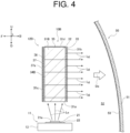
- the light source unit 10B is provided with a second light emitting layer 36 between a first reflective part 34B and a back surface 31c in the support member 31B of the light generating part 12B.
- This second light emitting layer 36 is the same as the first light emitting layer 32, and in the third embodiment, the second light emitting layer 36 is formed in the form of a thin film by subjecting deposition treatment to the back surface 31c.
- the second light emitting layer 36 is formed of a material of the same composition as the first light emitting layer 32, and emits generated light Lg of the same color (red light in the third embodiment).
- the light source unit 10B is provided with a second sealing part 37 for sealing the second light emitting layer 36.
- This second sealing part 37 is the same as the first sealing part 33, and in the third embodiment, the second sealing part 37 is provided so as to cover the second light emitting layer 36.
- the light source unit 10B is provided with the first reflective part 34B on an outer surface 37a (the front side in the front-rear direction and the side opposite to the emission direction De) in the second sealing part 37.
- This first reflective part 34B is formed by bonding aluminum, silver, or the like to the outer surface 37A by vapor deposition, painting, or the like.
- This light source unit 10B is provided with the second light emitting layer 36 between the first reflective part 34B and the back surface 31c, and therefore the generated light Lg which is red light can be emitted also from the second light emitting layer 36 by using the excitation light Le which travels to the back surface 31c directly or by reflection by the second reflective parts 35.
- a portion of the generated light Lg from the second light emitting layer 36 goes toward the front surface 31b directly or by reflection by the second reflective parts 35, and passes through the first light emitting layer 32 to be emitted in the emission direction De (the front side thereof) from the light source unit 10B.
- the other portion of the generated light Lg from the second light emitting layer 36 travels to the side opposite to the emission direction De, passes through the second sealing part 37, is reflected by the first reflecting part 34B, passes through the second sealing part 37 again, and then goes toward the back surface 31c directly or by reflection by the second reflective parts 35, passes through the first light emitting layer 32, and is emitted in the emission direction De. Therefore, in addition to the generated light Lg emitted from the first light emitting layer 32, the generated light Lg emitted from the second light emitting layer 36 can pass through the first light emitting layer 32 and be emitted in the emission direction De, so that the light source unit 10B can obtain a large amount of light. Thus, the light source unit 10B can perform surface emission more effectively and brightly while the first light emitting layer 32 and the second light emitting layer 36 are more efficiently disposed.
- the light source unit 10B of the third embodiment has basically the same configuration as the light source unit 10 of the first embodiment, and therefore the same effects as in the first embodiment can be obtained.
- the second light emitting layer 36 is provided between the first reflective part 34B and the back surface 31c. Therefore, in the light source unit 10B, in addition to the generated light Lg emitted from the first light emitting layer 32, the generated light Lg emitted from the second light emitting layer 36 can be emitted in the emission direction De, and therefore it is possible to perform surface emission more effectively and brightly while ensuring reliability.
- the light source unit 10B of the third embodiment as a light source unit according to the present disclosure can appropriately perform surface emission.
- the first light emitting layer 32 and the second light emitting layer 36 are made to emit generated light Lg of the same color (red light) (formed of the same material), but may be made to emit generated light Lg of different colors from each other, and are not limited to the configuration of the third embodiment.
- the first embodiment by appropriately selecting a host material and a dopant material, it is possible to emit the generated light Lg of different colors from each other.
- the combination of colors of the first light emitting layer 32 and the second light emitting layer 36 it is possible to synthesize colors that cannot be formed by each of the first light emitting layer 32 and the second light emitting layer 36 alone, so that it is possible to increase the diversity of colors for surface emission.
- the light source unit 10C is one obtained by modifying the configuration of the support member 31 in the light generating part 12 of the light source unit 10 of the first embodiment.
- a basic concept and a configuration of the light source unit 10C are the same as those of the light source unit 10 of the first embodiment, and therefore the same reference numerals are affixed to parts having the same configurations, and detailed description will be omitted.
- a first light emitting layer 32C is sectioned into a first light emitting section 38 and a second light emitting section 39 aligned vertically.
- the first light emitting section 38 and the second light emitting section 39 are irradiated with excitation light Le from a light source part 11 (light source 21 thereof)
- the first light emitting section 38 and the second light emitting section 39 each emit mutually different colored generated light Lg.
- the color of the generated light Lg to be emitted by each of the first light emitting section 38 and the second light emitting section 39 can be set by appropriately selecting a host material and a dopant material, as described in the first embodiment.
- a mask is provided on an area to form the second light emitting section 39 in a front surface 31b and the area is subject to deposition treatment, so that the thin film-like first light emitting section 38 is formed.
- a mask is provided on the first light emitting section 38 in the front surface 31b, and the first light emitting section 38 is subject to deposition treatment, so that the second light emitting section 39 is formed.
- the first light emitting section 38 emits generated light Lg of red light
- the second light emitting section 39 emits generated light Lg of yellow light.
- a sealing part 33 is provided as in the first embodiment, so that the first light emitting layer 32C having the first light emitting section 38 and the second light emitting section 39 can be sealed with the sealing part 33.
- the first light emitting layer 32C has the first light emitting section 38 and the second light emitting section 39, and therefore this light source unit 10C can perform surface emission while the first light emitting section 38 and the second light emitting section 39 have the colors different from each other. Consequently, the light source unit 10C can combine a plurality of colors to perform surface emission while ensuring reliability.
- the light source unit 10C of the fourth embodiment has basically the same configuration as the light source unit 10 of the first embodiment, and therefore the same effects as in the first embodiment can be obtained.
- the first light emitting layer 32C is sectioned into two or more light emitting sections (the first light emitting section 38 and the second light emitting section 39) each having emitting different colored generated light Lg in response to the excitation light Le. Therefore, the light source unit 10C can illuminate the first light emitting layer 32C as a plurality of different colored areas, and can combine a plurality of colors to perform surface emission while ensuring reliability.
- the light source unit 10C of the fourth embodiment as a light source unit according to the present disclosure can appropriately perform surface emission.
- the first light emitting layer 32C is vertically sectioned into two sections, namely, the first light emitting section 38 and the second light emitting section 39.
- the shape, the positional relationship, the color emitted, the number, and the like of each of the light emitting sections can be set appropriately, and are not limited to the configuration of the fourth embodiment.
- a first light emitting section 38 is provided in the center and a second light emitting section 39 is provided so as to surround the first light emitting section 38.
- the first light emitting section 38 and the second light emitting section 39 in the first light emitting layer 32C perform light emission with respective different colors simultaneously by the excitation light Le from the light source part 11.
- the first light emitting section 38 and the second light emitting section 39 may be illuminated separately.
- a light source part having the same configuration as that of the light source part 11 is provided on the upper side, and a light shielding member or a reflective member is provided inside the support member 31C in accordance with the separation between the first light emitting section 38 and the second light emitting section 39.
- the vehicular lamp 50D is one obtained by changing the installation position in the lamp chamber 52 of the vehicular lamp 50 of the first embodiment, and is used as a tail lamp.
- a basic concept and a configuration of the vehicular lamp 50D are the same as those of the vehicular lamp 50 of the first embodiment, and therefore the same reference numerals are affixed to parts having the same configurations, and detailed description will be omitted.
- a light source part 11D emits excitation light Le, has a light source 21 and a support substrate 22, and is provided with the support substrate 22 on a heat radiating member 13D via a bracket or the like.
- the heat radiating member 13D is disposed such that a surface mounted with the support substrate 22 is directed toward an outer lens 51D.
- the outer lens 51D thereof includes a light emitting layer 32D as a light emitting part that emits generated light Lg by being irradiated with excitation light Le, a sealing part 33D that seals the light emitting layer 32D, and a filter part 53D that inhibits the transmission of ultraviolet rays.
- the light emitting layer 32D is provided on an inner surface 51a of the outer lens 51D in the fifth embodiment. This light emitting layer 32D is formed in the form of a thin film by the inner surface 51a being subjected to deposition treatment in the same manner as the light emitting layer 32 of the first embodiment, and emits the generated light Lg of red light.
- the light emitting layer 32D is transparent in a state in which there is no irradiation with the excitation light Le.
- the sealing part 33D is provided on an inner surface of the light emitting layer 32D (an inner surface that is on the lamp chamber 52 side).
- the sealing part 33D is formed of a material that transmits the excitation light Le and the generated light Lg.
- the sealing part 33D is provided on the inner side of the light emitting layer 32D so as to cover an entire surface of the light emitting layer 32D. Consequently, the sealing part 33D cooperates with the outer lens 51D to prevent the light emitting layer 32D from being exposed to air.
- the filter part 53D is provided on an outer surface 51b of the outer lens 51D in the fifth embodiment. Similar to the filter part 53 of the first embodiment, this filter part 53D is formed in the form of a thin film by applying a coating having a function of UV cutting to the outer surface 51B, and is transparent.
- the vehicular lamp 50D of the fifth embodiment electric power is supplied from a lighting control circuit to turn on the light source 21 of the light source part 11D, so that the excitation light Le emitted from the light emitting surface 21a of the light source 21 goes to the outer lens 51D.
- the entire surface of the light emitting layer 32D provided on the inner surface 51a of the outer lens 51D is irradiated with the excitation light Le.
- the light emitting layer 32D is excited by being irradiated with the excitation light Le to emit the generated light Lg that is red light, and the generated light Lg travels to the outside of the lamp chamber 52 through the outer lens 51 and is emitted from the vehicular lamp 50D.
- This generated light Lg as the red light is emitted outward from the outer lens 51D, so that the light emitting layer 32D, namely, the outer lens 51D can be caused to perform surface emission. Therefore, the vehicular lamp 50D can perform surface emission while ensuring reliability, and can function as a tail lamp.
- the vehicular lamp 50D is provided with the filter part 53D having a function of UV cutting on the outer lens 51D, and therefore can prevent, for example, ultraviolet rays included in external light from penetrating the outer lens 51 and traveling to the light emitting layer 32D, and can prevent the light emitting layer 32D from being degraded by the ultraviolet rays. Furthermore, the light emitting layer 32D is transparent in a state in which there is no irradiation with the excitation light Le, and the filter part 53D is transparent, and therefore the vehicular lamp 50D can have good appearance similar to a transparent tail lamp.
- the vehicular lamp 50D may be provided with a reflective part similar to the first reflective part 34 of the first embodiment on an inner wall surface (a surface on the lamp chamber 52 side) of the lamp housing that constitutes the lamp chamber 52.
- the generated light Lg emitted by the light emitting layer 32D can be efficiently used and it is possible to perform surface emission more brightly.
- the vehicular lamp 50D of the fifth embodiment has basically the same configuration as the vehicular lamp 50 of the first embodiment, and therefore the same effects as in the first embodiment can be obtained.
- the vehicular lamp 50D can have a simpler configuration than the vehicular lamp 50 of the first embodiment since the light generating part 12 is eliminated by providing the light emitting layer 32D on the outer lens 51D.
- the vehicular lamp 50D of the fifth embodiment as the light emitting device for a mobile body according to the present disclosure can appropriately perform surface emission.
- the excitation light Le from the light source part 11D travels to the outer lens 51D (light emitting layer 32D provided therein) directly.
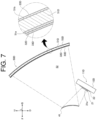
- the vehicular lamp 50D may be provided with a reflective part 41, and a light source part 11D may be provided such that a light emitting surface 21a of a light source 21 faces the reflective part 41.
- the vehicular lamp 50D of FIG. 7 with such a configuration can cause the outer lens 51D to perform surface emission while preventing the light source part 11D from being visually recognized from outside.
- the light emitting layer 32D is provided on the inner surface 51a and the filter part 53D is provided on the outer surface 51b.
- the positional relationship with respect to the outer lens 51D can be set appropriately and is not limited to the configuration of the fifth embodiment.
- the single light source part 11D is used.
- the plurality of light source parts 11D may be disposed appropriately toward the outer lens 51D to make the entire outer lens 51D perform surface emission, and is not limited to the configuration of the fifth embodiment.
- the outer lens 51D is provided with the light emitting layer 32D, the sealing part 33D, and the filter part 53D to function as a tail lamp.
- an inner lens may be provided between the light source part 11D and the outer lens 51D, and the inner lens may be configured to have at least the light emitting layer 32D and the sealing part 33D.
- the vehicular lamp can be used as a tail lamp in a rear combination lamp.
- a light source unit having the same configuration as such a configuration and provided with the light emitting layer 32D that performs yellow surface emission like the second light emitting section 39 of the third embodiment is provided, so that a tail lamp and a turn lamp in the rear combination lamp can be formed together.
- the light emitting layer (32 or the like) has the shape described above and emits the generated light Lg of red light (and partly yellow light in the fourth and fifth embodiments).
- the shape of the light emitting layer and the color of the generated light Lg to be emitted may be set appropriately, and are not limited to the configuration of each embodiment. Consequently, the light source unit and the light emitting apparatus for a mobile body can be each made to function as, for example, a tail lamp or a signal lamp corresponding to a variety of designs.
- the light source part (11, etc.) is disposed below the light generating part (12, etc.).
- the positional relationship between the light source part and the light generating part can be set appropriately and is not limited to the configuration of each embodiment.
- the sealing part 33 is provided so as to cover the light emitting layer (32, etc.) in the light generating part (12, etc.), and therefore the front surface 31b is positioned such that the sealing part 33 surrounds and frame the light emitting layer when viewed from the front.
- the sealing part 33 is transparent, and therefore the excitation light Le and the generated light Lg are emitted from the periphery of the light emitting layer, and the light emitting layer can be surrounded and illuminated, and gradation can be formed together with the light emitting layer.
- the same reflective part as the first reflective part 34 and the second reflective parts 35 is provided or a light-shielding member is provided, so that it is possible to perform surface emission in a single color.
- the support part (support member 31) of the light generating part (12, etc.) is a rectangle (hexahedron in the second embodiment).
- the support part is provided with a light emitting part (light emitting layer 32) that emits generated light Lg by being irradiated with excitation light Le from the light source part 11, and a reflective part (first reflecting part 34) on the back surface 31c on the opposite side of the emission direction De to the generated light Lg
- the shape may be set as appropriate and is not limited to the configuration of the first embodiment.
- the support part may be configured, for example, to be formed in a rectangular solid having a box shape with an open end by using glass or the like, to be provided with a light emitting part therein and to be provided with a reflective part (first reflective part 34) on the back surface 31c on the opposite side to the emission direction De of the generated light Lg.
- the light emitting part is accommodated in the box-shaped support part in a state in which the red phosphorescent material or the like described in the first embodiment is dissolved in a solvent such as dichloroethane and the open end is sealed with a plate-like member, so that the light emitting part can be provided inside the box-shaped support part.
- the second reflective parts 35 are provided on all of the upper surface 31d, the first side surface 31e, and the second side surface 31f, which are side surfaces connecting the front surface 31b and the back surface 31c at the different positions from the incident surface 31a, but may not be provided, or may be only partially provided, and is not limited to the configuration of the first embodiment.
- each of the embodiments illustrates a vehicular lamp (50, etc.) used for an automobile as a light emitting device for a mobile body
- a light emitting device for a mobile body used for a mobile body such as a train, a linear motor car, an airplane
- the light emitting device for a mobile body is not limited to the configuration of each of the embodiments described above.
Landscapes
- Engineering & Computer Science (AREA)
- General Engineering & Computer Science (AREA)
- Physics & Mathematics (AREA)
- Microelectronics & Electronic Packaging (AREA)
- Optics & Photonics (AREA)
- Non-Portable Lighting Devices Or Systems Thereof (AREA)
- Planar Illumination Modules (AREA)
- Semiconductor Lasers (AREA)
Abstract
Description
- The present disclosure relates to a light source unit and a light emitting device for a mobile body.
- A light source unit is used, for example, as a vehicular lamp having a signal light function such as a tail lamp, and is considered to perform surface emission (see, for example, PTL 1). This light source unit includes a light source, a plate-shaped light guide lens that guides light therefrom, and a lens member that emits the guided light. In this light source unit, the light guide lens internally guides the light diffused from the light source and emits the guided light from an exit slope, so that the light emits through the lens member in a substantially uniform manner.
- PTL 1:
Japanese Unexamined Patent Application Publication No. 2017-092010 - However, the above conventional light source unit emits light in the substantially uniform manner, and there is room for improvement from the viewpoint of uniform light emission, that is, appropriate surface emission.
- The present disclosure has been made in view of the above circumstances, and we have appreciated that it would be desirable to provide a light source unit capable of appropriately performing surface emission.
- According to an aspect of the present disclosure, there is provided a light source unit including: a light source part that emits excitation light; a light emitting part that emits generated light by being irradiated with the excitation light; a support part that guides the excitation light to the light emitting part while supporting the light emitting part; and a reflective part provided on a back surface of the support part, the back surface being on a side opposite to an emission direction of the generated light.
- According to the present disclosure, it is possible to appropriately perform surface emission.
-
-
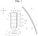
Fig. 1 is an explanatory diagram illustrating a state in which a light source unit is provided in a vehicular lamp as an example of a light emitting device for a mobile body including the light source unit of a first embodiment of a light source unit according to this embodiment. -
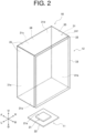
Fig. 2 is an explanatory diagram schematically illustrating the light source unit of the first embodiment. -
Fig. 3 is an explanatory diagram schematically illustrating a light source unit of a second embodiment in a similar manner toFig. 2 . -
Fig. 4 is an explanatory diagram schematically illustrating a light source unit of a third embodiment in a similar manner toFig. 1 . -
Fig. 5 is an explanatory diagram schematically illustrating a light source unit of a fourth embodiment in a similar manner toFig. 2 . -
Fig. 6 is an explanatory diagram schematically illustrating a vehicular lamp of a fifth embodiment in a similar manner toFig. 1 . -
Fig. 7 is an explanatory diagram schematically illustrating a vehicular lamp as another example of a vehicular lamp of the fifth embodiment. - Hereinafter, each embodiment in which a light source unit according to this embodiment is applied to a vehicular lamp as an example of a light emitting device for a mobile body will be described with reference to the drawings. In
Fig. 1 , a state in which generated light Lg emits in the emission direction De is illustrated schematically, which does not necessarily coincide with an actual state. - A
light source unit 10 of a first embodiment according to an embodiment of the light source unit of this embodiment will be described with reference toFig. 1 andFig. 2 . As illustrated inFIG. 1 , thelight source unit 10 of the first embodiment is used as avehicular lamp 50 of a vehicle such as an automobile as an example of a mobile body, and is suitable for a signal lamp, a position lamp or a signature lamp, and an example in which the light source unit is used for a rear combination lamp is illustrated in the first embodiment. In the following description, in thevehicular lamp 50, the direction of travel of a vehicle mounted with thevehicular lamp 50 upon advancement is defined as the front-rear direction (the front side of the vehicle is denoted by F and the rear side of the vehicle is denoted by B), the vertical direction is defined as the up-down direction (the upper side is denoted by U and the lower side is denoted by D), and the direction orthogonal to the front-rear direction and the up-down direction is defined as the left-right direction (the right side of a driver is denoted by R and the left side of the driver is denoted by L). - The
vehicular lamp 50 is disposed on each of both right and left sides of the rear of the vehicle and is configured to have thelight source unit 10 installed in alamp chamber 52 formed by covering a lamp housing, which is open on one side, with an outer lens from the open side. The lamp housing has a hollow shape having an open first end and a closed second end, constitutes a mounting place for thelight source unit 10 and houses a lighting drive device for lighting control of the light source unit 10 (light source 21 thereof). While enabling the emission of light (generated light Lg described below) from thelight source unit 10 housed in the lamp housing (light chamber 52), theouter lens 51 covers the emitted light. Theouter lens 51 is provided with afilter part 53 having a function of UV (ultraviolet) cutting for blocking the transmission of ultraviolet rays, namely, blocking (suppressing) the transmission of light in an ultraviolet wavelength band. Thefilter part 53 is formed by a coating having a function of UV cutting provided on a surface of theouter lens 51 in the first embodiment, and is transparent. Therefore, thelight source unit 10 emits light (generated light Lg) toward the side on which theouter lens 51 is provided, and the direction toward theouter lens 51 is defined as the emission direction De. - The
light source unit 10 has alight source part 11, alight generating part 12, and aheat radiating member 13, as illustrated inFig. 1 andFig. 2 . Theheat radiating member 13 is a heat sink that radiates heat from the light source part 11 (light source 21 thereof) to the outside. Theheat radiating member 13 is formed of a material having excellent thermal conductivity (a material having low thermal resistance) such as metal and resin, and may have comb-teeth shaped heat radiating fins for securing a heat radiating area. Theheat radiating member 13 is mounted with thelight source part 11 and provided in thelamp chamber 52. - The
light source part 11 emits excitation light Le for emitting (exciting) the generated light Lg from the light generating part 12 (light emitting layer 32 thereof (light emitting part)), and has thelight source 21 and asupport substrate 22. Thelight source 21 is composed of, for example, a semiconductor type light source such as an LED (light emitting diode), an OEL (organic electro-luminescence) and an OLED (organic EL) (organic light-emitting diode). Thelight source 21 is disposed below thelight generating part 12, and alight emitting surface 21a is directed upward, namely, toward thelight generating part 12, and emits light upward from thelight emitting surface 21a so as to form a Lambertian distribution. Thelight source 21 emits blue light from thelight emitting surface 21a as an example of the excitation light Le. Thelight source 21 is not limited to one that emits blue light, but can be one that emits light of a wavelength (such as violet light or ultraviolet light in the first embodiment) shorter than the wavelength of the generated light Lg generated in the light emitting layer 32 (light generating part 12). - The
support substrate 22 is mounted with thelight source 21 thereon, and is provided with a wiring pattern for energizing thelight source 21. Thesupport substrate 22 is provided on theheat radiating member 13 via a bracket or the like. Thesupport substrate 22 enables power supply to thelight source 21 from a lighting control circuit via the wiring pattern, and enables thelight source 21 to be turned on and off as appropriate. - The
light generating part 12 has a support member 31 (support part), thelight emitting layer 32, asealing part 33, a firstreflective part 34, and secondreflective parts 35. Thesupport member 31 is provided in thelamp chamber 52 independently of thelight source part 11 by a bracket or the like. Thesupport member 31 is formed of a material capable of transmitting the excitation light Le emitted from thelight source 21, and has a rectangular parallelepiped shape in the first embodiment. Thesupport member 31 may be a rigid member formed of, for example, glass or the like, or a flexible member formed of acrylic resin, a thermoplastic material, or the like, but in the first embodiment, the rigid member is used. Thesupport member 31 is also capable of transmitting the generated light Lg emitted by thelight emitting layer 32. In thesupport member 31, a surface facing thelight source 21 of thelight source part 11 is anincident surface 31a. Theincident surface 31a is a surface on which the excitation light Le from thelight source 21 of thelight source part 11 is incident into the inside of thesupport member 31, and the size and the positional relationship of theincident surface 31a to thelight emitting surface 21a of thelight source 21 are set so as to allow the excitation light Le to be efficiently incident. The excitation light Le is guided inside thesupport member 31 to enable irradiation over the entire surface of thelight emitting layer 32. - In the
support member 31, a surface on the emission direction De side of the generated light Lg (the front side in the emission direction De), namely, the surface facing theouter lens 51 is defined as afront surface 31b, and a surface located on the side opposite to thefront surface 31b (the rear side in the emission direction De) is defined as aback surface 31c. In thesupport member 31, among four side surfaces connecting thefront surface 31b and therear surface 31c, the surface located on the side opposite to thelower incident surface 31a is defined as anupper surface 31d, the side surface on the near side (left side in the left-right direction) in front view ofFig. 1 andFig. 2 is defined as afirst side surface 31e, and the surface located on the back side (right side in the left-right direction) in front view ofFig. 1 andFig. 2 is define as asecond side surface 31f. - The
light emitting layer 32 is excited by being irradiated with the excitation light Le from thelight source 21 and emits the generated light Lg. - The
light emitting layer 32 is provided on thefront surface 31b of thesupport member 31 so as to expand in a planar shape (in a wide area along thefront surface 31b), and in the first embodiment, thelight emitting layer 32 is formed in a thin film form by subjecting deposition treatment to thefront surface 31b. Thislight emitting layer 32 emits the generated light Lg toward the emission direction De by being irradiated with the excitation light Le, and also emits the generated light Lg toward the side opposite to the emission direction De. Thelight emitting layer 32 is transparent in a state in which there is no irradiation with the excitation light Le. As such alight emitting layer 32, for example, an organic material doped with about 5% of a red phosphorescent material ((btp)2Ir(acac)) such as acetylacetone as a dopant material to a host material such as polyvinylcarbazole is used. In this case, thelight emitting layer 32 emits red light as the generated light Lg by irradiation with the excitation light Le. Therefore, thelight emitting layer 32 functions as a light emitting part that emits the generated light Lg by being irradiated with the excitation light Le, and thesupport member 31 functions as a support part that supports thelight emitting layer 32 as a light emitting part. - The host material and the dopant material in the
light emitting layer 32 are not limited to the above materials and can be selected as appropriate. For example, the dopant material can emit the generated light Lg of blue light by using a blue phosphorescent material (FIrpic), can emit the generated light Lg of yellow light by using a yellow phosphorescent material ((bzp)2Ir(acac)), and can emit the generated light Lg of green light by using a green phosphorescent material ((ppy)2Ir(acac)). For the host material in thelight emitting layer 32, an inorganic material such as YAG (Yttrium Aluminum Garnet) can be used. - The sealing
part 33 is provided in order to seal thelight emitting layer 32 and is formed of a material that transmits the excitation light Le and the generated light Lg. The sealingpart 33 may be, for example, a rigid member formed of, for example, glass or epoxy resin, as well as thesupport member 31, or may be a flexible member formed of acrylic resin, thermoplastic material, or the like, and is the same member as thesupport member 31 in the first embodiment. The sealingpart 33 is provided on thefront surface 31b of thesupport member 31 so as to cover the entirelight emitting layer 32, that is, so as to be in contact with thefront surface 31b around the top, bottom, left and right of thelight emitting layer 32 in the direction along thefront surface 31b of thesupport member 31, and is provided so as to cover the entire surface of thelight emitting layer 32. Consequently, the sealingpart 33 cooperates with thesupport member 31 to prevent thelight emitting layer 32 from being exposed to air. This is due to the fact that thelight emitting layer 32 deteriorates when thelight emitting layer 32 is exposed to air. - The first
reflective part 34 and the secondreflective parts 35 prevent the excitation light Le emitted from the light source part 11 (light source 21) and incident into thesupport member 31 and the generated light Lg emitted from thelight emitting layer 32 and incident into thesupport member 31 from emitting to the outside of thesupport member 31. The firstreflective part 34 and the secondreflective parts 35 are formed by bonding aluminum, silver, or the like to the support member 31 (surfaces thereof) by vapor deposition, painting, or the like. The firstreflective part 34 is provided over the entire surface of theback surface 31c of thesupport member 31, and reflects the excitation light Le and the generated light Lg that travel to theback surface 31c. The secondreflective parts 35 are provided over the entire surfaces of theupper surface 31d, thefirst side surface 31e and thesecond side surface 31f of thesupport member 31, that is, over the entire surfaces of the side surfaces that are laid between thefront surface 31b and theback surface 31c at positions different from theincident surface 31a, and reflects the excitation light Le and the generated light Lg that travel to each surface thereof. - Now, the operation (lighting) of the
vehicular lamp 50 configured as described above will be described. In thevehicular lamp 50, electric power is supplied from the lighting control circuit, and thelight source 21 of thelight source part 11 is turned on, so that the excitation light Le emitted from thelight emitting surface 21a of thelight source 21 goes to thelight generating part 12 on the upper side. The excitation light Le is incident into thesupport member 31 from theincident surface 31a, and a portion of the excitation light Le goes to thefront surface 31b and the other portion of the excitation light goes to theback surface 31c, theupper surface 31d, thefirst side surface 31e, and thesecond side surface 31f. The other portion of the excitation light Le is reflected by the firstreflective part 34 on theback surface 31c or the secondreflective parts 35 on theupper surface 31d, thefirst side surface 31e and thesecond side surface 31f, and goes to thefront surface 31b directly or by repeated reflection. Consequently, thesupport member 31 guides the incident excitation light Le internally, so that the entirefront surface 31b (light emittinglayer 32 thereof) can be irradiated with the excitation light Le. - The
light emitting layer 32 provided on thefront surface 31b is irradiated with the excitation light Le directed to thefront surface 31b. Thelight emitting layer 32 is excited by the irradiation with the excitation light Le and emits the generated light Lg which is red light. A portion of the generated light Lg travels in the emission direction De, and the other portion of the generated light Lg travels into thesupport member 31. The generated light Lg that travels into thesupport member 31 is reflected by the firstreflective part 34 or the secondreflective parts 35, so that the generated light Lg goes toward thefront surface 31b directly or by repeated reflection, passes through thelight emitting layer 32, and travels in the emission direction De. The generated light Lg which travels in the emission directions De can travel to theouter lens 51 as light emitted from thelight source unit 10, travels to the outside of thelamp chamber 52 through theouter lens 51, and is emitted from thevehicular lamp 50. This generated light Lg as red light is emitted from theouter lens 51 in the front direction and can be made to function as a rear combination lamp. - In addition, the
vehicular lamp 50 is provided with thefilter part 53 having a function of UV cutting on theouter lens 51. Therefore, thevehicular lamp 50 can prevent, for example, ultraviolet rays included in external light from penetrating theouter lens 51 and traveling to thelight emitting layer 32 of thelight generating part 12 of thelight source unit 10, and can prevent thelight emitting layer 32 from being degraded by the ultraviolet rays. - Now, the action of this
light source unit 10 will be described. For the purpose of this explanation, an organic light emitting diode, which is considered as a configuration to realize surface emission in a light source, is used as a comparative example. This organic light emitting diode has a structure in which an electrode, an organic layer, and an electrode are stacked on a substrate, and realizes surface emission by flow of a current between the electrodes and emission of electroluminescence. - In the
light source unit 10 of the first embodiment, thelight emitting layer 32 is provided on thefront surface 31b of thesupport member 31 by using an organic material in a state of expanding in the planar shape, and therefore the generated light Lg can be emitted evenly over the entirelight emitting layer 32 expanded in the planar shape, and can cause surface emission in an area where thelight emitting layer 32 is provided. Therefore, thelight source unit 10 of the first embodiment can realize surface emission while ensuring the reliability of the light source, compared to an organic light emitting diode. Consequently, thelight source unit 10 can easily obtain red light emitted in a plane shape while ensuring reliability as thevehicular lamp 50. In particular, thelight source unit 10 is provided with thelight emitting layer 32 on thefront surface 31b located in the emission direction De (the front side thereof) in thesupport member 31, and therefore it is possible to efficiently emit the generated light Lg which is red light generated in thelight emitting layer 32, and it is possible to obtain brighter surface emission. - In addition, the
light source unit 10 of the first embodiment has a configuration in which thelight emitting layer 32 provided in thesupport member 31 of thelight generating part 12 emits red light as the generated light Lg by the irradiation with the excitation light Le from the light source part 11 (light source 21), and therefore no electrical degradation such as electrical degradation of an organic light emitting diode occurs. This is due to the fact that the organic light emitting diode undergoes electrical degradation when a current flows between electrodes to emit electroluminescence. Therefore, thelight source unit 10 of the first embodiment can improve the reliability of the light source as compared with the organic light emitting diode. - The
light source unit 10 is provided with the firstreflective part 34 on theback surface 31c located on the side opposite to the emission direction De in thesupport member 31 of thelight generating part 12. Therefore, thelight source unit 10 can prevent the excitation light Le from the light source part 11 (light source 21) and the generated light Lg emitted by thelight emitting layer 32 from emitting from theback surface 31c to the outside of thesupport member 31, and can reflect the excitation light Le and the generated light Lg, which go toward theback surface 31c, toward thefront surface 31b. Consequently, thelight source unit 10 can efficiently use the excitation light Le from thelight source part 11 to emit the generated light Lg in the emission direction De (the front side thereof), and can perform surface emission more brightly. In particular, thelight source unit 10 has thesupport member 31 that allows transmission of the generated light Lg, and is provided with the firstreflective part 34 on theback surface 31c, and therefore the generated light Lg that is directed to theback surface 31c can also be reflected by the firstreflective part 34 to be emitted in the emission direction De (the front side thereof), so that the generated light Lg emitted by thelight emitting layer 32 can be efficiently used. - In addition to the first
reflective part 34 on theback surface 31c, thelight source unit 10 is provided with the secondreflective parts 35 on the side surfaces (theupper surface 31d, thefirst side surface 31e, and thesecond side surface 31f) different from theincident surface 31a in thesupport member 31. Therefore, thelight source unit 10 can prevent the excitation light Le and the generated light Lg from emitting from the side surfaces of thesupport member 31 other than theincident surface 31a of thesupport member 31 to the outside of thesupport member 31. Consequently, thelight source unit 10 can more efficiently use the excitation light Le to emit the generated light Lg from thelight emitting layer 32 in the emission direction De (the front side thereof), so that it is possible to perform surface emission more brightly. - The
light source unit 10 of the first embodiment can obtain each of the following effects. - The
light source unit 10 includes thelight source part 11, thelight emitting layer 32 as a light emitting part that emits the generated light Lg by be irradiated with the excitation light Le from the light source part, thesupport member 31 as a support part that guides the excitation light Le to thelight emitting layer 32 while supporting thelight emitting layer 32, and the firstreflective part 34 as a reflective part provided on theback surface 31c of the support member. Therefore, thelight source unit 10 can reflect the excitation light Le and the generated light Lg, which go to theback surface 31c, toward thefront surface 31b while preventing the excitation light Le and the generated light Lg from emitting from theback surface 31c to the outside of thesupport member 31, can efficiently use the excitation light Le from thelight source part 11 to emit the generated light Lg in the emission direction De, and can perform surface emission more brightly. In addition, thelight source unit 10 is provided with thelight source part 11 and thelight generating part 12 independently from each other, and therefore the degree of freedom of the installation position of each of thelight source part 11 and thelight generating part 12 can be increased, and the surface-emittinglight emitting layer 32 that performs surface emission can be visually recognized while preventing thelight source part 11 from being visually recognized from outside. That is, in thelight source unit 10, thelight source part 11 can be provided at such a position as not to be visually recognized or can be shielded by a shielding member, and thelight emitting layer 32 can be provided at such a position as to be visually recognized. - The
light source unit 10 is provided with the secondreflective parts 35 on the side surfaces (theupper surface 31d, thefirst side surface 31e, and thesecond side surface 31f) laid between thefront surface 31b on the emission direction De side and theback surface 31c at the position different from theincident surface 31a in thesupport member 31. Therefore, thelight source unit 10 can prevent the excitation light Le and the generated light Lg from emitting from the above side surfaces of thesupport member 31 to the outside of thesupport member 31, and can more efficiently use the excitation light Le to emit the generated light Lg in the emission direction De from thelight emitting layer 32, so that it is possible to perform surface emission more brightly. - The
vehicular lamp 50 as a light emitting device for a mobile body includes thelight source unit 10, theouter lens 51 that emits the generated light Lg from the light source unit, and thefilter part 53 that suppresses transmission of ultraviolet rays and is provided in theouter lens 51. Therefore, thevehicular lamp 50 can efficiently use the excitation light Le to emit the generated light Lg in the emission direction De from thelight emitting layer 32, so that it is possible to perform surface emission more brightly and prevent thelight emitting layer 32 from being degraded by ultraviolet rays. Consequently, thevehicular lamp 50 can realize surface emission while ensuring reliability. - Accordingly, the
light source unit 10 of the first embodiment as a light source unit according to the present disclosure can appropriately perform surface emission. - In the first embodiment, the
support member 31 as the support part is composed of a rigid member. However, the support part (support member 31) may be composed of a flexible member or any other configuration, and is not limited to the configuration of the first embodiment. When thesupport member 31 is composed of a flexible member, the sealingpart 33 can also be composed of a flexible member, so that thelight emitting layer 32, which is a light emitting surface in thelight generating part 12, can be curved together with thesupport member 31. Therefore, thelight source unit 10 can have a greater degree of freedom in the shape thereof while enabling surface emission, and can improve usability. - In the first embodiment, the
back surface 31c is the flat surface. However, theback surface 31c may be, for example, a curved surface or any other configuration, as long as theback surface 31c is a surface located on the opposite side to the emission direction De of the generated light Lg in the support part (support member 31), and is not limited to the configuration of the first embodiment. - Now, a
light source unit 10A of a second embodiment which is an embodiment of the present disclosure will be described with reference toFig. 3 . Thelight source unit 10A is one obtained by modifying the configuration of thesupport member 31 in thelight generating part 12 of thelight source unit 10 of the first embodiment. A basic concept and a configuration of thelight source unit 10A are the same as those of thelight source unit 10 of the first embodiment, and therefore the same reference numerals are affixed to parts having the same configurations, and detailed description will be omitted. - First, according to the
light source unit 10A of the second embodiment, in asupport member 31A of alight generating part 12A, an upper surface 31dA, a first side surface 31eA, and a second side surface 31fA are inclined in a state of being directed toward afront surface 31b. That is, the upper surface 31dA is inclined so as to be displaced upward from aback surface 31c toward thefront surface 31b. The first side surface 31eA is inclined so as to be displaced to the left side in the left-right direction (near side of the figure in front view) from theback surface 31c toward thefront surface 31b. The second side surface 31fA is inclined so as to be displaced to the right side in the left-right direction (back side of the figure in front view) from theback surface 31c toward thefront surface 31b. - In this
light source unit 10A, the upper surface 31dA, the first side surface 31eA, and the second side surface 31fA of thesupport member 31A are inclined in a state of being directed toward thefront surface 31b, and therefore thelight source unit 10A can more actively reflect excitation light Le and generated light Lg in thesupport member 31A, especially excitation light Le incident from theincident surface 31a toward thefront surface 31b. Consequently, thelight source unit 10A can perform surface emission more effectively and brightly while ensuring reliability. - The
light source unit 10A of the second embodiment has basically the same configuration as thelight source unit 10 of the first embodiment, and therefore the same effects as in the first embodiment can be obtained. - In addition to the above, in the
light source unit 10A, the upper surface 31dA, the first side surface 31eA, and the second side surface 31fA of thesupport member 31A are inclined in a state of being directed toward thefront surface 31b. Therefore, thelight source unit 10A can more actively reflect the excitation light Le and the generated light Lg in thesupport member 31A toward thefront surface 31b, and can perform surface emission more effectively and brightly while ensuring reliability. - Accordingly, the
light source unit 10A of the second embodiment as a light source unit according to the present disclosure can appropriately perform surface emission. - In the second embodiment, the upper surface 31dA, the first side surface 31eA, and the second side surface 31fA, namely, entire side surfaces laid between the
front surface 31b and theback surface 31c at positions different from theincident surface 31a are inclined in the state of being directed toward thefront surface 31b. However, it is sufficient to incline at least one part (at least one side surface) of the above side surfaces in a state of being directed toward thefront surface 31b, and is not limited to the configuration of the second embodiment. - Now, a
light source unit 10B of a third embodiment which is an embodiment of the present disclosure will be described with reference toFig. 4 . Thelight source unit 10B is one obtained by modifying the configuration of thesupport member 31 in thelight generating part 12 of thelight source unit 10 of the first embodiment. A basic concept and a configuration of thelight source unit 10B are the same as those of thelight source unit 10 of the first embodiment, and therefore the same reference numerals are affixed to parts having the same configurations, and detailed description will be omitted. - First, according to the
light source unit 10B of the third embodiment, in asupport member 31B of a light generating part 12B, alight emitting layer 32 provided on afront surface 31b is defined as a firstlight emitting layer 32 as a first light emitting part, and a sealingpart 33 provided so as to cover the firstlight emitting layer 32 is defined as a first sealingpart 33. Thelight source unit 10B is provided with a secondlight emitting layer 36 between a first reflective part 34B and aback surface 31c in thesupport member 31B of the light generating part 12B. This second light emittinglayer 36 is the same as the firstlight emitting layer 32, and in the third embodiment, the secondlight emitting layer 36 is formed in the form of a thin film by subjecting deposition treatment to theback surface 31c. Herein, the secondlight emitting layer 36 is formed of a material of the same composition as the firstlight emitting layer 32, and emits generated light Lg of the same color (red light in the third embodiment). - The
light source unit 10B is provided with asecond sealing part 37 for sealing the secondlight emitting layer 36. This second sealingpart 37 is the same as the first sealingpart 33, and in the third embodiment, the second sealingpart 37 is provided so as to cover the secondlight emitting layer 36. - The
light source unit 10B is provided with the first reflective part 34B on anouter surface 37a (the front side in the front-rear direction and the side opposite to the emission direction De) in the second sealingpart 37. This first reflective part 34B is formed by bonding aluminum, silver, or the like to the outer surface 37A by vapor deposition, painting, or the like. - This
light source unit 10B is provided with the secondlight emitting layer 36 between the first reflective part 34B and theback surface 31c, and therefore the generated light Lg which is red light can be emitted also from the secondlight emitting layer 36 by using the excitation light Le which travels to theback surface 31c directly or by reflection by the secondreflective parts 35. A portion of the generated light Lg from the secondlight emitting layer 36 goes toward thefront surface 31b directly or by reflection by the secondreflective parts 35, and passes through the firstlight emitting layer 32 to be emitted in the emission direction De (the front side thereof) from thelight source unit 10B. The other portion of the generated light Lg from the secondlight emitting layer 36 travels to the side opposite to the emission direction De, passes through the second sealingpart 37, is reflected by the first reflecting part 34B, passes through the second sealingpart 37 again, and then goes toward theback surface 31c directly or by reflection by the secondreflective parts 35, passes through the firstlight emitting layer 32, and is emitted in the emission direction De. Therefore, in addition to the generated light Lg emitted from the firstlight emitting layer 32, the generated light Lg emitted from the secondlight emitting layer 36 can pass through the firstlight emitting layer 32 and be emitted in the emission direction De, so that thelight source unit 10B can obtain a large amount of light. Thus, thelight source unit 10B can perform surface emission more effectively and brightly while the firstlight emitting layer 32 and the secondlight emitting layer 36 are more efficiently disposed. - The
light source unit 10B of the third embodiment has basically the same configuration as thelight source unit 10 of the first embodiment, and therefore the same effects as in the first embodiment can be obtained. - In addition to the above, in the
light source unit 10B, the secondlight emitting layer 36 is provided between the first reflective part 34B and theback surface 31c. Therefore, in thelight source unit 10B, in addition to the generated light Lg emitted from the firstlight emitting layer 32, the generated light Lg emitted from the secondlight emitting layer 36 can be emitted in the emission direction De, and therefore it is possible to perform surface emission more effectively and brightly while ensuring reliability. - Accordingly, the
light source unit 10B of the third embodiment as a light source unit according to the present disclosure can appropriately perform surface emission. - In the third embodiment, the first
light emitting layer 32 and the secondlight emitting layer 36 are made to emit generated light Lg of the same color (red light) (formed of the same material), but may be made to emit generated light Lg of different colors from each other, and are not limited to the configuration of the third embodiment. In this case, as described in the first embodiment, by appropriately selecting a host material and a dopant material, it is possible to emit the generated light Lg of different colors from each other. With this configuration, by considering the combination of colors of the firstlight emitting layer 32 and the secondlight emitting layer 36, it is possible to synthesize colors that cannot be formed by each of the firstlight emitting layer 32 and the secondlight emitting layer 36 alone, so that it is possible to increase the diversity of colors for surface emission. - Now, a
light source unit 10C of a fourth embodiment which is an embodiment of the present disclosure will be described with reference toFig. 5 . Thelight source unit 10C is one obtained by modifying the configuration of thesupport member 31 in thelight generating part 12 of thelight source unit 10 of the first embodiment. A basic concept and a configuration of thelight source unit 10C are the same as those of thelight source unit 10 of the first embodiment, and therefore the same reference numerals are affixed to parts having the same configurations, and detailed description will be omitted. - According to the
light source unit 10C of the fourth embodiment, in a support member 31C of a light generating part 12C, a first light emitting layer 32C is sectioned into a firstlight emitting section 38 and a secondlight emitting section 39 aligned vertically. When the firstlight emitting section 38 and the secondlight emitting section 39 are irradiated with excitation light Le from a light source part 11 (light source 21 thereof), the firstlight emitting section 38 and the secondlight emitting section 39 each emit mutually different colored generated light Lg. The color of the generated light Lg to be emitted by each of the firstlight emitting section 38 and the secondlight emitting section 39 can be set by appropriately selecting a host material and a dopant material, as described in the first embodiment. Then, for example, a mask is provided on an area to form the secondlight emitting section 39 in afront surface 31b and the area is subject to deposition treatment, so that the thin film-like firstlight emitting section 38 is formed. Thereafter, a mask is provided on the firstlight emitting section 38 in thefront surface 31b, and the firstlight emitting section 38 is subject to deposition treatment, so that the secondlight emitting section 39 is formed. In the first embodiment, the firstlight emitting section 38 emits generated light Lg of red light, and the secondlight emitting section 39 emits generated light Lg of yellow light. Thereafter, a sealingpart 33 is provided as in the first embodiment, so that the first light emitting layer 32C having the firstlight emitting section 38 and the secondlight emitting section 39 can be sealed with the sealingpart 33. - The first light emitting layer 32C has the first
light emitting section 38 and the secondlight emitting section 39, and therefore thislight source unit 10C can perform surface emission while the firstlight emitting section 38 and the secondlight emitting section 39 have the colors different from each other. Consequently, thelight source unit 10C can combine a plurality of colors to perform surface emission while ensuring reliability. - The
light source unit 10C of the fourth embodiment has basically the same configuration as thelight source unit 10 of the first embodiment, and therefore the same effects as in the first embodiment can be obtained. - In addition to the above, in the
light source unit 10C, the first light emitting layer 32C is sectioned into two or more light emitting sections (the firstlight emitting section 38 and the second light emitting section 39) each having emitting different colored generated light Lg in response to the excitation light Le. Therefore, thelight source unit 10C can illuminate the first light emitting layer 32C as a plurality of different colored areas, and can combine a plurality of colors to perform surface emission while ensuring reliability. - Accordingly, the
light source unit 10C of the fourth embodiment as a light source unit according to the present disclosure can appropriately perform surface emission. - In the fourth embodiment, the first light emitting layer 32C is vertically sectioned into two sections, namely, the first
light emitting section 38 and the secondlight emitting section 39. However, as long as the first light emitting layer 32C is sectioned into two or more light emitting sections each having emitting different colored generated light Lg in response to the excitation light Le, the shape, the positional relationship, the color emitted, the number, and the like of each of the light emitting sections can be set appropriately, and are not limited to the configuration of the fourth embodiment. As an example of other shapes, for example, a firstlight emitting section 38 is provided in the center and a secondlight emitting section 39 is provided so as to surround the firstlight emitting section 38. - In the fourth embodiment, it is assumed that the first
light emitting section 38 and the secondlight emitting section 39 in the first light emitting layer 32C perform light emission with respective different colors simultaneously by the excitation light Le from thelight source part 11. However, the firstlight emitting section 38 and the secondlight emitting section 39 may be illuminated separately. In this case, for example, when the firstlight emitting section 38 and the secondlight emitting section 39 are vertically aligned as in the fourth embodiment, a light source part having the same configuration as that of thelight source part 11 is provided on the upper side, and a light shielding member or a reflective member is provided inside the support member 31C in accordance with the separation between the firstlight emitting section 38 and the secondlight emitting section 39. Consequently, when thelight source part 11 is turned on, only the secondlight emitting section 39 can be illuminated, and when the upper light source part is turned on, only the firstlight emitting section 38 can be illuminated, and the firstlight emitting section 38 illuminated in red can be used as a tail lamp and the secondlight emitting section 39 illuminated in yellow can be used as a turn lamp (signal light). - Now, a
vehicular lamp 50D of a fifth embodiment which is an embodiment of the present disclosure will be described with reference toFig. 6 . Thevehicular lamp 50D is one obtained by changing the installation position in thelamp chamber 52 of thevehicular lamp 50 of the first embodiment, and is used as a tail lamp. A basic concept and a configuration of thevehicular lamp 50D are the same as those of thevehicular lamp 50 of the first embodiment, and therefore the same reference numerals are affixed to parts having the same configurations, and detailed description will be omitted. - A light source part 11D emits excitation light Le, has a
light source 21 and asupport substrate 22, and is provided with thesupport substrate 22 on aheat radiating member 13D via a bracket or the like. Theheat radiating member 13D is disposed such that a surface mounted with thesupport substrate 22 is directed toward anouter lens 51D. - The
outer lens 51D thereof includes alight emitting layer 32D as a light emitting part that emits generated light Lg by being irradiated with excitation light Le, a sealingpart 33D that seals thelight emitting layer 32D, and afilter part 53D that inhibits the transmission of ultraviolet rays. Thelight emitting layer 32D is provided on aninner surface 51a of theouter lens 51D in the fifth embodiment. Thislight emitting layer 32D is formed in the form of a thin film by theinner surface 51a being subjected to deposition treatment in the same manner as thelight emitting layer 32 of the first embodiment, and emits the generated light Lg of red light. Thelight emitting layer 32D is transparent in a state in which there is no irradiation with the excitation light Le. - The sealing
part 33D is provided on an inner surface of thelight emitting layer 32D (an inner surface that is on thelamp chamber 52 side). The sealingpart 33D is formed of a material that transmits the excitation light Le and the generated light Lg. The sealingpart 33D is provided on the inner side of thelight emitting layer 32D so as to cover an entire surface of thelight emitting layer 32D. Consequently, the sealingpart 33D cooperates with theouter lens 51D to prevent thelight emitting layer 32D from being exposed to air. - The
filter part 53D is provided on anouter surface 51b of theouter lens 51D in the fifth embodiment. Similar to thefilter part 53 of the first embodiment, thisfilter part 53D is formed in the form of a thin film by applying a coating having a function of UV cutting to the outer surface 51B, and is transparent. - In the
vehicular lamp 50D of the fifth embodiment, electric power is supplied from a lighting control circuit to turn on thelight source 21 of the light source part 11D, so that the excitation light Le emitted from thelight emitting surface 21a of thelight source 21 goes to theouter lens 51D. The entire surface of thelight emitting layer 32D provided on theinner surface 51a of theouter lens 51D is irradiated with the excitation light Le. Then, thelight emitting layer 32D is excited by being irradiated with the excitation light Le to emit the generated light Lg that is red light, and the generated light Lg travels to the outside of thelamp chamber 52 through theouter lens 51 and is emitted from thevehicular lamp 50D. This generated light Lg as the red light is emitted outward from theouter lens 51D, so that thelight emitting layer 32D, namely, theouter lens 51D can be caused to perform surface emission. Therefore, thevehicular lamp 50D can perform surface emission while ensuring reliability, and can function as a tail lamp. - The
vehicular lamp 50D is provided with thefilter part 53D having a function of UV cutting on theouter lens 51D, and therefore can prevent, for example, ultraviolet rays included in external light from penetrating theouter lens 51 and traveling to thelight emitting layer 32D, and can prevent thelight emitting layer 32D from being degraded by the ultraviolet rays. Furthermore, thelight emitting layer 32D is transparent in a state in which there is no irradiation with the excitation light Le, and thefilter part 53D is transparent, and therefore thevehicular lamp 50D can have good appearance similar to a transparent tail lamp. - Herein, a part of the generated light Lg emitted by the
light emitting layer 32D travels toward the inner side of thelamp chamber 52. Therefore, thevehicular lamp 50D may be provided with a reflective part similar to the firstreflective part 34 of the first embodiment on an inner wall surface (a surface on thelamp chamber 52 side) of the lamp housing that constitutes thelamp chamber 52. When thevehicular lamp 50D has such a configuration, the generated light Lg emitted by thelight emitting layer 32D can be efficiently used and it is possible to perform surface emission more brightly. - The
vehicular lamp 50D of the fifth embodiment has basically the same configuration as thevehicular lamp 50 of the first embodiment, and therefore the same effects as in the first embodiment can be obtained. - In addition to the above, the
vehicular lamp 50D can have a simpler configuration than thevehicular lamp 50 of the first embodiment since thelight generating part 12 is eliminated by providing thelight emitting layer 32D on theouter lens 51D. - Accordingly, the
vehicular lamp 50D of the fifth embodiment as the light emitting device for a mobile body according to the present disclosure can appropriately perform surface emission. - In the fifth embodiment, the excitation light Le from the light source part 11D (light source 21) travels to the
outer lens 51D (light emittinglayer 32D provided therein) directly. However, as illustrated inFIG. 7 , thevehicular lamp 50D may be provided with areflective part 41, and a light source part 11D may be provided such that alight emitting surface 21a of alight source 21 faces thereflective part 41. Thevehicular lamp 50D ofFIG. 7 with such a configuration can cause theouter lens 51D to perform surface emission while preventing the light source part 11D from being visually recognized from outside. - In the fifth embodiment, in the
outer lens 51D, thelight emitting layer 32D is provided on theinner surface 51a and thefilter part 53D is provided on theouter surface 51b. However, as long as thefilter part 53D and thelight emitting layer 32D are provided in theouter lens 51D in this order from the outside (outside of thevehicular lamp 50D), the positional relationship with respect to theouter lens 51D can be set appropriately and is not limited to the configuration of the fifth embodiment. - Further, in the fifth embodiment, it is assumed that the single light source part 11D is used. However, the plurality of light source parts 11D may be disposed appropriately toward the
outer lens 51D to make the entireouter lens 51D perform surface emission, and is not limited to the configuration of the fifth embodiment. - Further, in the fifth embodiment, the
outer lens 51D is provided with thelight emitting layer 32D, the sealingpart 33D, and thefilter part 53D to function as a tail lamp. However, an inner lens may be provided between the light source part 11D and theouter lens 51D, and the inner lens may be configured to have at least thelight emitting layer 32D and the sealingpart 33D. With such a configuration, the vehicular lamp can be used as a tail lamp in a rear combination lamp. At this time, a light source unit having the same configuration as such a configuration and provided with thelight emitting layer 32D that performs yellow surface emission like the secondlight emitting section 39 of the third embodiment is provided, so that a tail lamp and a turn lamp in the rear combination lamp can be formed together. - Although the light source unit and the light emitting apparatus for a mobile body of the present disclosure are described above on the basis of each embodiment, the specific configuration is not limited to each embodiment, and design changes, additions, and the like are allowed without departing from the gist of the invention in each claim of the scope of the patent claims.
- In each of the embodiments, it is assumed that the light emitting layer (32 or the like) has the shape described above and emits the generated light Lg of red light (and partly yellow light in the fourth and fifth embodiments). However, the shape of the light emitting layer and the color of the generated light Lg to be emitted may be set appropriately, and are not limited to the configuration of each embodiment. Consequently, the light source unit and the light emitting apparatus for a mobile body can be each made to function as, for example, a tail lamp or a signal lamp corresponding to a variety of designs.
- In each of the first embodiment to the fourth embodiment, the light source part (11, etc.) is disposed below the light generating part (12, etc.). However, as long as the generated light Lg is emitted from the light emitting layer (32, 36, etc.) of the light generating part t by the excitation light Le from the light source part, the positional relationship between the light source part and the light generating part can be set appropriately and is not limited to the configuration of each embodiment.
- Furthermore, in each of the first embodiment to the fourth embodiment, the sealing
part 33 is provided so as to cover the light emitting layer (32, etc.) in the light generating part (12, etc.), and therefore thefront surface 31b is positioned such that the sealingpart 33 surrounds and frame the light emitting layer when viewed from the front. With this configuration, the sealingpart 33 is transparent, and therefore the excitation light Le and the generated light Lg are emitted from the periphery of the light emitting layer, and the light emitting layer can be surrounded and illuminated, and gradation can be formed together with the light emitting layer. In contrast, at the position framed by the sealingpart 33 on thefront surface 31b, the same reflective part as the firstreflective part 34 and the secondreflective parts 35 is provided or a light-shielding member is provided, so that it is possible to perform surface emission in a single color. - In each of the first embodiment to the fourth embodiment, the support part (support member 31) of the light generating part (12, etc.) is a rectangle (hexahedron in the second embodiment). However, as long as the support part is provided with a light emitting part (light emitting layer 32) that emits generated light Lg by being irradiated with excitation light Le from the
light source part 11, and a reflective part (first reflecting part 34) on theback surface 31c on the opposite side of the emission direction De to the generated light Lg, the shape may be set as appropriate and is not limited to the configuration of the first embodiment. The support part may be configured, for example, to be formed in a rectangular solid having a box shape with an open end by using glass or the like, to be provided with a light emitting part therein and to be provided with a reflective part (first reflective part 34) on theback surface 31c on the opposite side to the emission direction De of the generated light Lg. In this case, the light emitting part is accommodated in the box-shaped support part in a state in which the red phosphorescent material or the like described in the first embodiment is dissolved in a solvent such as dichloroethane and the open end is sealed with a plate-like member, so that the light emitting part can be provided inside the box-shaped support part. - In each of the first embodiment to the fourth embodiment, the second
reflective parts 35 are provided on all of theupper surface 31d, thefirst side surface 31e, and thesecond side surface 31f, which are side surfaces connecting thefront surface 31b and theback surface 31c at the different positions from theincident surface 31a, but may not be provided, or may be only partially provided, and is not limited to the configuration of the first embodiment. - Although each of the embodiments illustrates a vehicular lamp (50, etc.) used for an automobile as a light emitting device for a mobile body, a light emitting device for a mobile body used for a mobile body such as a train, a linear motor car, an airplane may be used, and the light emitting device for a mobile body is not limited to the configuration of each of the embodiments described above.
- The respective configurations of the
light source units vehicular lamps -
- 10, 10A, 10B, 10C light source unit
- 11, 11D light source part
- 31, 31A, 31B, 31C support member (as an example of a support part)
- 31a incident surface
- 31b front surface
- 31c back surface
- 31d, 31dA upper surface (as an example of a side surface)
- 31e, 31eA first side surface (as an example of a side surface)
- 31f, 31fA second side surface (as an example of a side surface)
- 32, 32C, 32D (first) light emitting layer (as an example of a light emitting part)
- 34, 34B first reflective part
- 35 second reflective part
- 36 second light emitting layer (as an example of a second light emitting part)
- 38 first light emitting section (as an example of a light emitting section)
- 39 second light emitting section (as an example of a light emitting section)
- 50, 50D vehicular lamp (as an example of a light emitting device for a mobile body)
- 51, 51D outer lens
- 53, 53D filter part
- De emission direction
- Le excitation light
- Lg generated light
Claims (10)
- A vehicular lamp (50D) with a lamp chamber (52) comprising:a light source (21) for emitting blue excitation light (Le);a light emitting layer (32D) including organic material or inorganic material and for emitting red generated light (Lg) by being irradiated with the blue excitation light (Le); anda lens (51D) through which the red generated light (Lg) travels to the outside of the lamp chamber (52) so that the red generated light (Lg) is emitted from the vehicular lamp (50D),wherein the blue excitation light (Le) from the light source (21) travels to the light emitting layer (32D) directly so that the light emitting layer (32D) emits the red generated light (Lg) and performs surface emission.
- A vehicular lamp (50D) of claim 1, wherein the light emitting layer (32D) is provided on an inner surface (51a) of the lens (51D).
- A vehicular lamp (50D) of claim 2, wherein the vehicular lamp (50D) functions as a tail lamp.
- A vehicular lamp (50D) of any preceding claim, further comprising: a reflective part (41), anda light source part (11D) including the light source (21),wherein the light source (21) is provided such that a light emitting surface (21a) of the light source (21) faces the reflective part, and the light source part (11D) is prevented from being visually recognized from outside of the vehicle.
- A vehicular lamp (50D) of claim 4, further comprising:a support substrate (22) on which the light source (21) is mounted, anda heat radiating member (13D) for radiating heat from the light source (21),wherein the support substrate (22) is provided on the heat radiating member (13D).
- A vehicular lamp (50D) of any preceding claim, further comprising:a sealing part (33D) formed of a material that transmits the excitation light and the generated light,wherein the sealing part (33D) is provided on the inner side of the light emitting layer (32D) so as to cover an entire surface of the light emitting layer (32D) and cooperates with the lens (51D) to prevent the light emitting layer (32D) from being exposed to air.
- A vehicular lamp (50D) of claim 6, further comprising:a filter part (53D) provided on an outer surface (51b) of the lens (51D),wherein the filter part (53D) is formed in the form of thin film by applying a coating having a function of UV cutting to the outer surface (51b) of the lens (51D) and is transparent.
- A vehicular lamp (50D) of any preceding claim, wherein the light emitting layer (32D) is transparent in a state in which there is no irradiation with the blue excitation light (Le).
- A vehicular lamp (50D) of any preceding claim, wherein the light emitting layer (32D) includes at least one material from a red phosphorescent material, a blue phosphorescent material, a yellow phosphorescent material, and a green phosphorescent material.
- A vehicular lamp (50D) of any preceding claim, wherein the light emitting layer (32D) is formed in the form of a thin film including organic material.
Applications Claiming Priority (3)
| Application Number | Priority Date | Filing Date | Title |
|---|---|---|---|
| JP2019076253A JP2020174007A (en) | 2019-04-12 | 2019-04-12 | Light source unit, light emitting device for mobile body |
| EP20788259.8A EP3954943A4 (en) | 2019-04-12 | 2020-04-10 | LIGHT SOURCE UNIT, AND ELECTROLUMINESCENT DEVICE FOR MOVING BODY |
| PCT/JP2020/016207 WO2020209385A1 (en) | 2019-04-12 | 2020-04-10 | Light source unit, and light emitting device for mobile body |
Related Parent Applications (1)
| Application Number | Title | Priority Date | Filing Date |
|---|---|---|---|
| EP20788259.8A Division EP3954943A4 (en) | 2019-04-12 | 2020-04-10 | LIGHT SOURCE UNIT, AND ELECTROLUMINESCENT DEVICE FOR MOVING BODY |
Publications (2)
| Publication Number | Publication Date |
|---|---|
| EP4235021A2 true EP4235021A2 (en) | 2023-08-30 |
| EP4235021A3 EP4235021A3 (en) | 2023-09-06 |
Family
ID=72751329
Family Applications (2)
| Application Number | Title | Priority Date | Filing Date |
|---|---|---|---|
| EP23178902.5A Pending EP4235021A3 (en) | 2019-04-12 | 2020-04-10 | Light source unit, and light emitting device for mobile body |
| EP20788259.8A Withdrawn EP3954943A4 (en) | 2019-04-12 | 2020-04-10 | LIGHT SOURCE UNIT, AND ELECTROLUMINESCENT DEVICE FOR MOVING BODY |
Family Applications After (1)
| Application Number | Title | Priority Date | Filing Date |
|---|---|---|---|
| EP20788259.8A Withdrawn EP3954943A4 (en) | 2019-04-12 | 2020-04-10 | LIGHT SOURCE UNIT, AND ELECTROLUMINESCENT DEVICE FOR MOVING BODY |
Country Status (5)
| Country | Link |
|---|---|
| US (2) | US20220163183A1 (en) |
| EP (2) | EP4235021A3 (en) |
| JP (1) | JP2020174007A (en) |
| CN (1) | CN113710955A (en) |
| WO (1) | WO2020209385A1 (en) |
Families Citing this family (2)
| Publication number | Priority date | Publication date | Assignee | Title |
|---|---|---|---|---|
| WO2023127789A1 (en) * | 2021-12-28 | 2023-07-06 | 市光工業株式会社 | Light source unit for vehicular lighting tool and vehicular lighting tool |
| US12385619B1 (en) * | 2024-05-13 | 2025-08-12 | GM Global Technology Operations LLC | Lighting device for a vehicle |
Citations (2)
| Publication number | Priority date | Publication date | Assignee | Title |
|---|---|---|---|---|
| JP2017092010A (en) | 2015-11-17 | 2017-05-25 | スタンレー電気株式会社 | Light guide and vehicle lamp |
| EP3944345A1 (en) * | 2019-03-22 | 2022-01-26 | LG Innotek Co., Ltd. | Lighting module and lighting device comprising same |
Family Cites Families (30)
| Publication number | Priority date | Publication date | Assignee | Title |
|---|---|---|---|---|
| US5931566A (en) * | 1995-10-12 | 1999-08-03 | Valeo Sylvania L.L.C. | Colored and decorative lighting |
| JP2000326785A (en) | 1999-05-19 | 2000-11-28 | Ichikoh Ind Ltd | Vehicle lighting system |
| US6908220B2 (en) * | 2001-07-16 | 2005-06-21 | Toyoda Gosei Co., Ltd. | Vehicle lamp |
| US7781787B2 (en) * | 2001-11-16 | 2010-08-24 | Toyoda Gosei, Co., Ltd. | Light-emitting diode, led light, and light apparatus |
| JP3841670B2 (en) * | 2001-11-21 | 2006-11-01 | アルプス電気株式会社 | Bar-shaped light guide, surface light emitter, and liquid crystal display using the same |
| JP2006073202A (en) * | 2004-08-31 | 2006-03-16 | Nichia Chem Ind Ltd | Light emitting device |
| KR101271226B1 (en) * | 2006-02-16 | 2013-06-03 | 삼성디스플레이 주식회사 | Back light unit and liquid crystal display including the same |
| JP5431636B2 (en) * | 2006-07-14 | 2014-03-05 | 株式会社小糸製作所 | Vehicle sign light |
| JP4797944B2 (en) * | 2006-11-15 | 2011-10-19 | ソニー株式会社 | Light source device and display device |
| JP4765905B2 (en) * | 2006-11-17 | 2011-09-07 | 日亜化学工業株式会社 | Planar light emitting device and manufacturing method thereof |
| JP4678364B2 (en) * | 2006-12-05 | 2011-04-27 | スタンレー電気株式会社 | Light source device and vehicle headlamp |
| JP2008163809A (en) | 2006-12-27 | 2008-07-17 | Railway Technical Res Inst | engine |
| JP5066462B2 (en) * | 2008-02-29 | 2012-11-07 | スタンレー電気株式会社 | Vehicle lighting |
| JP2011187285A (en) * | 2010-03-08 | 2011-09-22 | Toshiba Corp | Light emitting device |
| JP2012014972A (en) * | 2010-07-01 | 2012-01-19 | Seiko Epson Corp | Light source device and projector |
| JP2013161626A (en) * | 2012-02-03 | 2013-08-19 | Harison Toshiba Lighting Corp | Strip-shaped lighting device |
| JP6045470B2 (en) | 2013-03-04 | 2016-12-14 | 信越化学工業株式会社 | Red lamp and vehicle lighting device |
| JP2015050148A (en) * | 2013-09-04 | 2015-03-16 | 株式会社小糸製作所 | Vehicle lamp |
| US9533613B2 (en) * | 2013-11-21 | 2017-01-03 | Ford Global Technologies, Llc | Photoluminescent fuel filler door |
| DE102014203245A1 (en) * | 2014-02-24 | 2015-08-27 | Automotive Lighting Reutlingen Gmbh | Lighting device of a motor vehicle |
| DE102014211833A1 (en) * | 2014-06-20 | 2015-12-24 | Osram Gmbh | Signaling by means of semiconductor light sources |
| CN107407834B (en) | 2015-03-16 | 2021-02-19 | 夏普株式会社 | Illumination device, display device, and television receiver |
| CN107407467B (en) * | 2015-03-18 | 2020-03-27 | 夏普株式会社 | Illumination device, display device, and television receiver |
| JP2017123317A (en) | 2016-01-08 | 2017-07-13 | パナソニックIpマネジメント株式会社 | Lighting device |
| DE102016005880A1 (en) * | 2016-05-13 | 2017-11-16 | Man Truck & Bus Ag | Luminaire with at least one light emitting diode (LED), in particular headlights with daytime running lights for a motor vehicle |
| US9889801B2 (en) * | 2016-07-14 | 2018-02-13 | Ford Global Technologies, Llc | Vehicle lighting assembly |
| JP6818504B2 (en) * | 2016-10-21 | 2021-01-20 | スタンレー電気株式会社 | Vehicle lighting |
| JP2018101534A (en) * | 2016-12-20 | 2018-06-28 | 株式会社小糸製作所 | Vehicle lighting |
| EP3355664A1 (en) * | 2017-01-30 | 2018-08-01 | odelo GmbH | Illuminant with fluorescent element and colour filter and light equipped with same |
| JP6894737B2 (en) * | 2017-03-27 | 2021-06-30 | 株式会社小糸製作所 | Vehicle lighting |
-
2019
- 2019-04-12 JP JP2019076253A patent/JP2020174007A/en active Pending
-
2020
- 2020-04-10 CN CN202080028390.7A patent/CN113710955A/en not_active Withdrawn
- 2020-04-10 EP EP23178902.5A patent/EP4235021A3/en active Pending
- 2020-04-10 US US17/602,347 patent/US20220163183A1/en not_active Abandoned
- 2020-04-10 WO PCT/JP2020/016207 patent/WO2020209385A1/en not_active Ceased
- 2020-04-10 EP EP20788259.8A patent/EP3954943A4/en not_active Withdrawn
-
2023
- 2023-01-27 US US18/160,805 patent/US12007090B2/en active Active
Patent Citations (2)
| Publication number | Priority date | Publication date | Assignee | Title |
|---|---|---|---|---|
| JP2017092010A (en) | 2015-11-17 | 2017-05-25 | スタンレー電気株式会社 | Light guide and vehicle lamp |
| EP3944345A1 (en) * | 2019-03-22 | 2022-01-26 | LG Innotek Co., Ltd. | Lighting module and lighting device comprising same |
Also Published As
| Publication number | Publication date |
|---|---|
| US20220163183A1 (en) | 2022-05-26 |
| CN113710955A (en) | 2021-11-26 |
| EP4235021A3 (en) | 2023-09-06 |
| US12007090B2 (en) | 2024-06-11 |
| EP3954943A4 (en) | 2022-12-21 |
| WO2020209385A1 (en) | 2020-10-15 |
| EP3954943A1 (en) | 2022-02-16 |
| US20230175664A1 (en) | 2023-06-08 |
| JP2020174007A (en) | 2020-10-22 |
Similar Documents
| Publication | Publication Date | Title |
|---|---|---|
| US11959613B2 (en) | Light source unit of vehicle lighting system and vehicle lighting system | |
| US12007090B2 (en) | Light source unit, and light emitting device for mobile body | |
| US20140321151A1 (en) | Illumination apparatus, vehicle headlamp, and downlight | |
| JP2019133794A (en) | Luminaire | |
| US12281774B2 (en) | Vehicle lamp having excitation light source, light conversion unit, and red lens | |
| JP4333776B2 (en) | control panel | |
| US20150226390A1 (en) | Light-producing assembly for a vehicle | |
| JP4218493B2 (en) | LED lights | |
| US12203624B2 (en) | Vehicle lamp having excitation light source, light conversion unit, and optical filter | |
| JP6191265B2 (en) | Lighting device | |
| JP5797045B2 (en) | Light emitting device, vehicle headlamp and lighting device | |
| JP6516502B2 (en) | Lighting device | |
| JP4013536B2 (en) | Lighting device | |
| JP2023098490A (en) | vehicle lamp | |
| CN107923589B (en) | Light modules for vehicle headlights | |
| CN105785572A (en) | Windshield display system | |
| US12455059B2 (en) | Light source unit for vehicular lighting tool and vehicular lighting tool | |
| CN106356436A (en) | Photoluminescent lighting apparatus for vehicles | |
| EP4641079A1 (en) | Vehicle lamp | |
| WO2019193522A1 (en) | Luminescent structure of a lamp | |
| US20260116287A1 (en) | Windowpane assembly for a motor vehicle | |
| JP2009199872A (en) | Light source device | |
| US10993301B2 (en) | Light-emitting diode arrangement | |
| WO2026023455A1 (en) | Semiconductor light-emitting device | |
| JP2023098489A (en) | Light source unit for vehicle lamp and vehicle lamp |
Legal Events
| Date | Code | Title | Description |
|---|---|---|---|
| PUAI | Public reference made under article 153(3) epc to a published international application that has entered the european phase |
Free format text: ORIGINAL CODE: 0009012 |
|
| STAA | Information on the status of an ep patent application or granted ep patent |
Free format text: STATUS: THE APPLICATION HAS BEEN PUBLISHED |
|
| REG | Reference to a national code |
Ref country code: DE Ref legal event code: R079 Free format text: PREVIOUS MAIN CLASS: F21S0043200000 Ipc: F21Y0115100000 |
|
| PUAL | Search report despatched |
Free format text: ORIGINAL CODE: 0009013 |
|
| AC | Divisional application: reference to earlier application |
Ref document number: 3954943 Country of ref document: EP Kind code of ref document: P |
|
| AK | Designated contracting states |
Kind code of ref document: A2 Designated state(s): AL AT BE BG CH CY CZ DE DK EE ES FI FR GB GR HR HU IE IS IT LI LT LU LV MC MK MT NL NO PL PT RO RS SE SI SK SM TR |
|
| AK | Designated contracting states |
Kind code of ref document: A3 Designated state(s): AL AT BE BG CH CY CZ DE DK EE ES FI FR GB GR HR HU IE IS IT LI LT LU LV MC MK MT NL NO PL PT RO RS SE SI SK SM TR |
|
| RIC1 | Information provided on ipc code assigned before grant |
Ipc: F21S 43/20 20180101ALI20230803BHEP Ipc: F21S 43/247 20180101ALI20230803BHEP Ipc: F21S 43/245 20180101ALI20230803BHEP Ipc: F21S 45/10 20180101ALI20230803BHEP Ipc: F21W 103/10 20180101ALI20230803BHEP Ipc: F21W 103/00 20180101ALI20230803BHEP Ipc: F21S 43/40 20180101ALI20230803BHEP Ipc: F21S 43/31 20180101ALI20230803BHEP Ipc: F21S 43/242 20180101ALI20230803BHEP Ipc: F21S 43/239 20180101ALI20230803BHEP Ipc: F21S 43/16 20180101ALI20230803BHEP Ipc: F21S 43/14 20180101ALI20230803BHEP Ipc: F21V 9/38 20180101ALI20230803BHEP Ipc: F21V 9/32 20180101ALI20230803BHEP Ipc: F21V 9/06 20180101ALI20230803BHEP Ipc: F21S 2/00 20160101ALI20230803BHEP Ipc: F21Y 115/15 20160101ALI20230803BHEP Ipc: F21Y 115/10 20160101AFI20230803BHEP |
|
| STAA | Information on the status of an ep patent application or granted ep patent |
Free format text: STATUS: REQUEST FOR EXAMINATION WAS MADE |
|
| 17P | Request for examination filed |
Effective date: 20240306 |
|
| RBV | Designated contracting states (corrected) |
Designated state(s): AL AT BE BG CH CY CZ DE DK EE ES FI FR GB GR HR HU IE IS IT LI LT LU LV MC MK MT NL NO PL PT RO RS SE SI SK SM TR |
|
| STAA | Information on the status of an ep patent application or granted ep patent |
Free format text: STATUS: EXAMINATION IS IN PROGRESS |
|
| 17Q | First examination report despatched |
Effective date: 20250325 |
|
| GRAP | Despatch of communication of intention to grant a patent |
Free format text: ORIGINAL CODE: EPIDOSNIGR1 |
|
| STAA | Information on the status of an ep patent application or granted ep patent |
Free format text: STATUS: GRANT OF PATENT IS INTENDED |
|
| INTG | Intention to grant announced |
Effective date: 20260217 |