EP4234954A1 - Fastener clip assembly with locking arms - Google Patents
Fastener clip assembly with locking arms Download PDFInfo
- Publication number
- EP4234954A1 EP4234954A1 EP23158365.9A EP23158365A EP4234954A1 EP 4234954 A1 EP4234954 A1 EP 4234954A1 EP 23158365 A EP23158365 A EP 23158365A EP 4234954 A1 EP4234954 A1 EP 4234954A1
- Authority
- EP
- European Patent Office
- Prior art keywords
- pair
- locking arms
- doghouse
- fastener clip
- platform
- Prior art date
- Legal status (The legal status is an assumption and is not a legal conclusion. Google has not performed a legal analysis and makes no representation as to the accuracy of the status listed.)
- Granted
Links
Images



Classifications
-
- F—MECHANICAL ENGINEERING; LIGHTING; HEATING; WEAPONS; BLASTING
- F16—ENGINEERING ELEMENTS AND UNITS; GENERAL MEASURES FOR PRODUCING AND MAINTAINING EFFECTIVE FUNCTIONING OF MACHINES OR INSTALLATIONS; THERMAL INSULATION IN GENERAL
- F16B—DEVICES FOR FASTENING OR SECURING CONSTRUCTIONAL ELEMENTS OR MACHINE PARTS TOGETHER, e.g. NAILS, BOLTS, CIRCLIPS, CLAMPS, CLIPS OR WEDGES; JOINTS OR JOINTING
- F16B5/00—Joining sheets or plates, e.g. panels, to one another or to strips or bars parallel to them
- F16B5/06—Joining sheets or plates, e.g. panels, to one another or to strips or bars parallel to them by means of clamps or clips
- F16B5/0607—Joining sheets or plates, e.g. panels, to one another or to strips or bars parallel to them by means of clamps or clips joining sheets or plates to each other
- F16B5/0621—Joining sheets or plates, e.g. panels, to one another or to strips or bars parallel to them by means of clamps or clips joining sheets or plates to each other in parallel relationship
- F16B5/0657—Joining sheets or plates, e.g. panels, to one another or to strips or bars parallel to them by means of clamps or clips joining sheets or plates to each other in parallel relationship at least one of the plates providing a raised structure, e.g. of the doghouse type, for connection with the clamps or clips of the other plate
Definitions
- the invention relates generally to devices for fastening together two or more objects.
- a number of devices and fasteners are currently available for fastening objects, such as body panels and automobile interior trim piece panels to the chassis of a vehicle, for example.
- a body panel may refer to, for example, any interior or exterior body panel on a vehicle, a plastic interior trim piece, headliner, or any interior trim piece.
- the panel may be any suitable exterior body panel, such as a fender, bumper, quarter panel, or door panel.
- the chassis of the vehicle may include any substrate, plate, body panel, structural framework, chassis component or subcomponent, wall, or any suitable object.
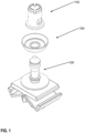
- Figure 1 is an exploded view of a fastener clip assembly, in accordance with some embodiments.
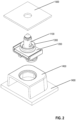
- Figure 2 is an exploded view of a fastener clip assembly, a body panel, and a chassis, in accordance with some embodiments.
- the fastener clip assembly comprises cap/grommet 1100 and pin/pin retainer 1200.
- Pin 1200 is configured to engage and secure itself on cap 1100 based at least upon cap 1100 being configured to fit over pin 1200 and into an interlocked position for the pin and the cap.
- the cap/pin assembly may be configured to attach to a slot/hole in chassis 1500 on one end by attaching the cap to the chassis slot and the pin to the cap, for example. On the other end, the assembly may be configured to attach to a doghouse or similar object in panel 1400.
- Pin 1200 may be configured to be coupled to a doghouse by being pressed into a slot in doghouse 1450 of panel 1400, for example.
- the doghouse may be coupled to panel 1400 by various means such as an adhesive, the doghouse may be molded onto panel 1400, etc.
- the two-piece assembly may be configured to retain various trim panels (such as panel 1400) to a car chassis (such as chassis 1500), for example, based at least upon the two-piece assembly being configured to couple to both the panel and the chassis.
- the fastener clip assembly may be configured to join various other comparable pairs of objects to each other.
- optional seal component 1300 is configured to attach over pin 1200 and to form a seal against the surface of chassis 1500 when the pin/cap assembly is attached to chassis 1500. In some embodiments, forming a seal against chassis surface 1500 prevents water, dirt, and other debris from entering through the chassis slot from the outside to the inside of the chassis. In some embodiments, choosing whether to use seal component 1300 may depend on the environment (such as the amount of water, dirt, etc. present).
- Figure 3 is a view of a cap of a fastener clip assembly, in accordance with some embodiments.
- pin/ cap shown here is only one example of a structure/method to couple the fastener clip to the chassis.
- cap 1100 is configured to be interlocked with pin 1200, and the two-part assembly is configured to engage and attach to a slot in a chassis and in addition engage and attach to a panel.
- cap 1100 comprises top portion 10 from which cylinder 15 extends, ending in cap foot 25.
- Cap 1100 may also include four crown portions 40 near top portion 10. Crown portions 40 are configured to bend and then snap back into position as the head of pin 1200 is inserted into cap 1100. Crown portions 40 are configured to engage a bottom surface of the head of the pin to lock the pin to the cap once the pin is inserted into the cap.
- small slots 42 may be placed between crown portions 40.
- the small slots may be configured to facilitate the bending of crown portions 40, such that the crown portions 40 can bend enough to allow for the engagement of the head of pin 1200.
- cap 1100 includes one or more tabs 35 (two are present in the shown embodiment) that are configured to collapse as cap 1100 is pushed into a slot in a chassis and then expand again on the other side of the chassis slot.
- the bottom sides 20 of tabs 35 are configured to secure cap 1100 to the slot in the chassis.
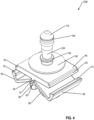
- Figure 4 is a view of a pin of a fastener clip assembly with a locking panel attachment, in accordance with some embodiments.
- Figure 5 is a view of a fastener clip assembly in locked position, in accordance with some embodiments.
- pin/cap shown here is only one example of a structure/method to couple the fastener clip to the chassis.
- Pin 1200 is configured to engage and lock itself into cap 1100.
- Pin 1200 in some embodiments, comprises pin head 170, which is tapered and is configured to guide the pin into the cap.
- a bottom surface 160 of the pin head 170 is configured to engage the top of crown portions 110 of cap 1100 and to lock against them in order to prevent easy removal of the pin from the cap.
- a removable seal may be configured to slide over pin 1200 through rim 250.
- the removable seal may be secured between base disk 140 and seal retainer 150.
- pin 1200 is configured to be pressed into and be coupled to a slot in doghouse 1450 of panel 1400.
- a pair of locking arms 60 is coupled to platform 50 via a pair of living hinges 65.
- Living hinges 65 are configured to facilitate a rotation of locking arms 60 relative to platform 50.
- other types of hinges may also be used.
- living hinges 65 may be stronger and more reliable based at least upon the living hinges 65 extending across the width of platform 50.
- Each of the pair of locking arms 60 is coupled to one of a pair of feet 80 whereby feet 80 are configured to rotate/move with locking arms 60 to which they are coupled.
- pin 1200 may be configured to be coupled to a slot in a doghouse in a panel.
- the locking arms 60 are in an unlocked, down position.
- feet 80 are configured to fit through the slot as pin 1200 is being inserted into a slot in the doghouse.
- the bottom sides of locking arms 60 are configured to come into contact with the top surface of the doghouse thereby causing locking arms 60 to be pushed up toward a locked position.
- the pair of hooks 70 are configured to engage corresponding lips 55 on platform 50 thereby coupling locking arms 60 to platform 50.
- the slot in the doghouse and the locking assembly at the bottom of the pin facilitate easier initial assembly as a user or a robot initially attaching the pin to the doghouse may do so by directly pushing the pin into the slot in the doghouse compared to other configurations that may require additional motions to complete initial assembly.
- feet 80 In the locked position, feet 80, by rotating with locking arms 60 and by already being inside the slot in the doghouse, are configured to engage the bottom of a slot in the doghouse of a panel, thereby coupling pin 1200 to the panel.
- pin 1200 may be configured to float within the slot in the doghouse. Some float may be beneficial, for example, to allow for some non-precise alignment between the slot in the doghouse and the slot in the chassis due to inconsistencies in manufacturing, for example.
- a pair of spring fingers 75 between each of locking arms 60 and feet 80 such that spring fingers 75 may be inside the slot when pin 1200 is in its locked position.
- Spring fingers 75 may be configured to spring-push the fastener assembly against the inner walls of the doghouse slot.
- spring fingers 75 are configured to provide spring action between pin 1200 and the inner walls of the slot such that the pin remains centered over the slot while concurrently providing some float for pin 1200 in the slot. As such, during insertion, pin 1200 has the highest chance of being center over the appropriate slot while still providing some float as needed.
- the fastener clip may be manufactured with injection molding using materials such as plastic nylon, polyoxymethylene (POM, also known as acetal), ABS, Polypropylene, rubber materials of various hardness, etc. It should be noted that different materials may be used for the different parts of the fastener clip.
- materials such as plastic nylon, polyoxymethylene (POM, also known as acetal), ABS, Polypropylene, rubber materials of various hardness, etc. It should be noted that different materials may be used for the different parts of the fastener clip.
- Figure 6 is an assembled view of a fastener clip assembly prior to engaging a panel, in accordance with some embodiments.
- Figure 7 is an assembled view of a fastener clip assembly in an engaged position on a panel, in accordance with some embodiments.
- Figure 6 shows the process of inserting the base of pin 1200 into the doghouse 1450 of panel 1400.
- Locking arms 60 are in the open position to facilitate the initial insertion of the pin into the slot.
- feet 80 are configured to fit into a slot in the doghouse.
- the bottom surface of platform 50 is configured to engage the top of the doghouse, thereby pushing the locking arms 60 into a locked position.
- Figure 7 shows the bottom of the pin coupled onto a slot in doghouse 1450 of panel 1400.
- feet 80 are in an expanded position engaging the bottom of doghouse thereby preventing the pin from separating from the doghouse.
- Hooks 70 are configured to engage lips 55 on platform 50, thereby maintaining the coupling of the pin to the doghouse.
Landscapes
- Engineering & Computer Science (AREA)
- General Engineering & Computer Science (AREA)
- Mechanical Engineering (AREA)
- Insertion Pins And Rivets (AREA)
- Clamps And Clips (AREA)
- Connection Of Plates (AREA)
Abstract
Description
- The invention relates generally to devices for fastening together two or more objects. A number of devices and fasteners are currently available for fastening objects, such as body panels and automobile interior trim piece panels to the chassis of a vehicle, for example. In some embodiments, a body panel may refer to, for example, any interior or exterior body panel on a vehicle, a plastic interior trim piece, headliner, or any interior trim piece. Additionally, the panel may be any suitable exterior body panel, such as a fender, bumper, quarter panel, or door panel. The chassis of the vehicle may include any substrate, plate, body panel, structural framework, chassis component or subcomponent, wall, or any suitable object.
- Other objects and advantages of the invention may become apparent upon reading the detailed description and upon reference to the accompanying drawings.
-
Figure 1 is an exploded view of a fastener clip assembly, in accordance with some embodiments. -
Figure 2 is an exploded view of a fastener clip assembly, a body panel, and a chassis, in accordance with some embodiments. -
Figure 3 is a view of a cap of a fastener clip assembly, in accordance with some embodiments. -
Figure 4 is a view of a pin of a fastener clip assembly with a locking panel attachment, in accordance with some embodiments. -
Figure 5 is a view of a fastener clip assembly in locked position, in accordance with some embodiments. -
Figure 6 is an assembled view of a fastener clip assembly prior to engaging a panel, in accordance with some embodiments. -
Figure 7 is an assembled view of a fastener clip assembly in an engaged position on a panel, in accordance with some embodiments. - While the invention is subject to various modifications and alternative forms, specific embodiments thereof are shown by way of example in the drawings and the accompanying detailed description. It should be understood, however, that the drawings and detailed description are not intended to limit the invention to the particular embodiments. This disclosure is instead intended to cover all modifications, equivalents, and alternatives falling within the scope of the present invention as defined by the appended claims.
-
Figure 1 is an exploded view of a fastener clip assembly, in accordance with some embodiments. -
Figure 2 is an exploded view of a fastener clip assembly, a body panel, and a chassis, in accordance with some embodiments. - In some embodiments, the fastener clip assembly comprises cap/
grommet 1100 and pin/pin retainer 1200.Pin 1200 is configured to engage and secure itself oncap 1100 based at least uponcap 1100 being configured to fit overpin 1200 and into an interlocked position for the pin and the cap. - The cap/pin assembly may be configured to attach to a slot/hole in
chassis 1500 on one end by attaching the cap to the chassis slot and the pin to the cap, for example. On the other end, the assembly may be configured to attach to a doghouse or similar object inpanel 1400.Pin 1200 may be configured to be coupled to a doghouse by being pressed into a slot indoghouse 1450 ofpanel 1400, for example. In some embodiments, the doghouse may be coupled topanel 1400 by various means such as an adhesive, the doghouse may be molded ontopanel 1400, etc. - In some embodiments, the two-piece assembly may be configured to retain various trim panels (such as panel 1400) to a car chassis (such as chassis 1500), for example, based at least upon the two-piece assembly being configured to couple to both the panel and the chassis. It should be noted that the fastener clip assembly may be configured to join various other comparable pairs of objects to each other.
- In some embodiments,
optional seal component 1300 is configured to attach overpin 1200 and to form a seal against the surface ofchassis 1500 when the pin/cap assembly is attached tochassis 1500. In some embodiments, forming a seal againstchassis surface 1500 prevents water, dirt, and other debris from entering through the chassis slot from the outside to the inside of the chassis. In some embodiments, choosing whether to useseal component 1300 may depend on the environment (such as the amount of water, dirt, etc. present). - It should be noted that multiple other structures and methods may be used for connecting the clip assembly to a chassis. The cap/pin, as shown and discussed here, are only one example of how to connect the fastener clip assembly to a chassis. Other types of fastener clip connections may be used and may connect to other types and shapes of slots in the chassis.
-
Figure 3 is a view of a cap of a fastener clip assembly, in accordance with some embodiments. - As was previously noted, the pin/ cap shown here is only one example of a structure/method to couple the fastener clip to the chassis.
- In some embodiments,
cap 1100 is configured to be interlocked withpin 1200, and the two-part assembly is configured to engage and attach to a slot in a chassis and in addition engage and attach to a panel. - In some embodiments,
cap 1100 comprisestop portion 10 from whichcylinder 15 extends, ending incap foot 25. - Cap 1100 may also include four
crown portions 40 neartop portion 10.Crown portions 40 are configured to bend and then snap back into position as the head ofpin 1200 is inserted intocap 1100.Crown portions 40 are configured to engage a bottom surface of the head of the pin to lock the pin to the cap once the pin is inserted into the cap. - In some embodiments,
small slots 42 may be placed betweencrown portions 40. The small slots may be configured to facilitate the bending ofcrown portions 40, such that thecrown portions 40 can bend enough to allow for the engagement of the head ofpin 1200. - In some embodiments,
cap 1100 includes one or more tabs 35 (two are present in the shown embodiment) that are configured to collapse ascap 1100 is pushed into a slot in a chassis and then expand again on the other side of the chassis slot. Thebottom sides 20 oftabs 35 are configured to securecap 1100 to the slot in the chassis. -
Figure 4 is a view of a pin of a fastener clip assembly with a locking panel attachment, in accordance with some embodiments. -
Figure 5 is a view of a fastener clip assembly in locked position, in accordance with some embodiments. - As was previously noted, the pin/cap shown here is only one example of a structure/method to couple the fastener clip to the chassis.
-
Pin 1200 is configured to engage and lock itself intocap 1100.Pin 1200, in some embodiments, comprisespin head 170, which is tapered and is configured to guide the pin into the cap. Abottom surface 160 of thepin head 170 is configured to engage the top of crown portions 110 ofcap 1100 and to lock against them in order to prevent easy removal of the pin from the cap. - A removable seal may be configured to slide over
pin 1200 throughrim 250. In some embodiments, the removable seal may be secured betweenbase disk 140 andseal retainer 150. - In some embodiments,
pin 1200 is configured to be pressed into and be coupled to a slot indoghouse 1450 ofpanel 1400. A pair of lockingarms 60 is coupled toplatform 50 via a pair ofliving hinges 65.Living hinges 65 are configured to facilitate a rotation of lockingarms 60 relative toplatform 50. In other embodiments, other types of hinges may also be used. In some embodiments,living hinges 65 may be stronger and more reliable based at least upon theliving hinges 65 extending across the width ofplatform 50. - Each of the pair of locking
arms 60 is coupled to one of a pair offeet 80 wherebyfeet 80 are configured to rotate/move with lockingarms 60 to which they are coupled. - In some embodiments,
pin 1200 may be configured to be coupled to a slot in a doghouse in a panel. In some embodiments, during insertion of the pin into the panel slot the lockingarms 60 are in an unlocked, down position. As such, by being in the unlocked, down position,feet 80 are configured to fit through the slot aspin 1200 is being inserted into a slot in the doghouse. As thepin 1200 is lowered into the slot, the bottom sides of lockingarms 60 are configured to come into contact with the top surface of the doghouse thereby causing lockingarms 60 to be pushed up toward a locked position. The pair ofhooks 70 are configured to engagecorresponding lips 55 onplatform 50 thereby coupling lockingarms 60 toplatform 50. - In some embodiments, the slot in the doghouse and the locking assembly at the bottom of the pin facilitate easier initial assembly as a user or a robot initially attaching the pin to the doghouse may do so by directly pushing the pin into the slot in the doghouse compared to other configurations that may require additional motions to complete initial assembly.
- In the locked position,
feet 80, by rotating with lockingarms 60 and by already being inside the slot in the doghouse, are configured to engage the bottom of a slot in the doghouse of a panel, therebycoupling pin 1200 to the panel. - In some embodiments,
pin 1200 may be configured to float within the slot in the doghouse. Some float may be beneficial, for example, to allow for some non-precise alignment between the slot in the doghouse and the slot in the chassis due to inconsistencies in manufacturing, for example. - In some embodiments, a pair of
spring fingers 75 between each of lockingarms 60 andfeet 80 such thatspring fingers 75 may be inside the slot whenpin 1200 is in its locked position.Spring fingers 75 may be configured to spring-push the fastener assembly against the inner walls of the doghouse slot. In some embodiments,spring fingers 75 are configured to provide spring action betweenpin 1200 and the inner walls of the slot such that the pin remains centered over the slot while concurrently providing some float forpin 1200 in the slot. As such, during insertion,pin 1200 has the highest chance of being center over the appropriate slot while still providing some float as needed. - In some embodiments, the fastener clip may be manufactured with injection molding using materials such as plastic nylon, polyoxymethylene (POM, also known as acetal), ABS, Polypropylene, rubber materials of various hardness, etc. It should be noted that different materials may be used for the different parts of the fastener clip.
-
Figure 6 is an assembled view of a fastener clip assembly prior to engaging a panel, in accordance with some embodiments. -
Figure 7 is an assembled view of a fastener clip assembly in an engaged position on a panel, in accordance with some embodiments. -
Figure 6 shows the process of inserting the base ofpin 1200 into thedoghouse 1450 ofpanel 1400. Lockingarms 60 are in the open position to facilitate the initial insertion of the pin into the slot. For example, in theopen position feet 80 are configured to fit into a slot in the doghouse. Then as the pin is being pushed into the slot, the bottom surface ofplatform 50 is configured to engage the top of the doghouse, thereby pushing the lockingarms 60 into a locked position. -
Figure 7 shows the bottom of the pin coupled onto a slot indoghouse 1450 ofpanel 1400. In the locked position,feet 80 are in an expanded position engaging the bottom of doghouse thereby preventing the pin from separating from the doghouse.Hooks 70 are configured to engagelips 55 onplatform 50, thereby maintaining the coupling of the pin to the doghouse. - It is understood that the implementation of other variations and modifications of the present invention in its various aspects will be apparent to those of ordinary skill in the art and that the invention is not limited by the specific embodiments described. It is therefore contemplated to cover by the present invention any and all modifications, variations or equivalents that fall within the spirit and scope of the basic underlying principles disclosed and claimed herein.
- One or more embodiments of the invention are described above. It should be noted that these and any other embodiments are exemplary and are intended to be illustrative of the invention rather than limiting. While the invention is widely applicable to various types of systems, a skilled person will recognize that it is impossible to include all of the possible embodiments and contexts of the invention in this disclosure. Upon reading this disclosure, many alternative embodiments of the present invention will be apparent to persons of ordinary skill in the art.
- The previous description of the disclosed embodiments is provided to enable any person skilled in the art to make or use the present invention. Various modifications to these embodiments will be readily apparent to those skilled in the art, and the generic principles defined herein may be applied to other embodiments without departing from the spirit or scope of the invention. Thus, the present invention is not intended to be limited to the embodiments shown herein but is to be accorded the widest scope consistent with the principles and novel features disclosed herein.
- The benefits and advantages that may be provided by the present invention have been described above with regard to specific embodiments. These benefits and advantages, and any elements or limitations that may cause them to occur or to become more pronounced are not to be construed as critical, required, or essential features of any or all of the claims. As used herein, the terms "comprises," "comprising," or any other variations thereof, are intended to be interpreted as non-exclusively including the elements or limitations that follow those terms. Accordingly, a system, method, or other embodiment that comprises a set of elements is not limited to only those elements, and may include other elements not expressly listed or inherent to the claimed embodiment.
- While the present invention has been described with reference to particular embodiments, it should be understood that the embodiments are illustrative and that the scope of the invention is not limited to these embodiments. Many variations, modifications, additions and improvements to the embodiments described above are possible. It is contemplated that these variations, modifications, additions and improvements fall within the scope of the invention as detailed within the following claims.
Claims (14)
- A fastener clip comprising:a top portion, wherein the top portion is configured to be coupled to a chassis,a bottom portion, wherein the bottom portion comprises:a platform;at least a pair of locking arms coupled to the platform via a pair of hinges,wherein the hinges are configured to facilitate a relative rotation between the locking arms and the platform;at least a pair of feet coupled to the locking arms and being configured to rotate with the locking arms,wherein the feet are configured to be partially inserted into a slot in a doghouse and, based at least on the locking arms being rotated, the feet are configured to rotate into the slot in the doghouse and to couple the bottom portion to the doghouse,wherein the locking arms are configured to be rotated based at least on the locking arms engaging a top surface of the doghouse as the fastener clip is pushed into the slot in the doghouse,wherein the locking arms are configured to be coupled to the platform at the end of the rotation.
- The fastener clip of claim 1, wherein the pair of hinges are a pair of living hinges.
- The fastener clip of claim 2, wherein the pair of living hinges is made of a same material as the platform and the pair of locking arms.
- The fastener clip of claim 1, wherein the bottom potion comprises a pair of spring fingers between the pair of locking arms and the pair of feet, wherein the pair of spring fingers is configured to maintain the fastener clip centered over the slot in the doghouse based at least upon the pair of spring fingers being configured to spring-push against the sides of the slot in the doghouse.
- The fastener clip of claim 4, wherein the spring fingers are configured to facilitate a certain amount of float between the fastener clip and the doghouse based at least upon a spring action of the spring fingers.
- The fastener clip of claim 1, wherein the pair of locking arms comprises a pair of hooks configured to lock the locking arms to the platform based at least upon the pair of hooks being configured to engage a corresponding pair of lips on the platform.
- The fastener clip of claim 6, wherein the pair of locking arms and the corresponding pair of lips extend across a width of the platform.
- A fastener clip assembly comprising:a chassis;a doghouse comprising a slot;a fastener clip comprising:a top portion, wherein the top portion is configured to be coupled to the chassis,a bottom portion, wherein the bottom portion comprises:a platform;at least a pair of locking arms coupled to the platform via a pair of hinges,wherein the hinges are configured to facilitate a relative rotation between the locking arms and the platform;at least a pair of feet coupled to the locking arms and being configured to rotate with the locking arms,wherein the feet are configured to be partially inserted into the slot in the doghouse and, based at least upon the locking arms being rotated, the feet are configured to rotate into the slot in the doghouse and to couple the bottom portion to the doghouse,wherein the locking arms are configured to be rotated based at least on the locking arms engaging a top surface of the doghouse as the fastener clip is pushed into the slot in the doghouse,wherein the locking arms are configured to be coupled to the platform at the end of the rotation.
- The fastener clip assembly of claim 8, wherein the pair of hinges are a pair of living hinges.
- The fastener clip assembly of claim 9, wherein the pair of living hinges is made of a same material as the platform and the pair of locking arms.
- The fastener clip assembly of claim 8, wherein the bottom potion comprises a pair of spring fingers between the pair of locking arms and the pair of feet, wherein the pair of spring fingers is configured to maintain the fastener clip centered over the slot in the doghouse based at least upon the pair of spring fingers being configured to spring-push against the sides of the slot in the doghouse.
- The fastener clip assembly of claim 8, wherein the spring fingers are configured to facilitate a certain amount of float between the fastener clip and the doghouse based at least upon a spring action of the spring fingers.
- The fastener clip assembly of claim 8, wherein the pair of locking arms comprises a pair of hooks configured to lock the locking arms to the platform based at least upon the pair of hooks being configured to engage a corresponding pair of lips on the platform.
- The fastener clip assembly of claim 13, wherein the pair of locking arms and the corresponding pair of lips extend across a width of the platform.
Applications Claiming Priority (2)
| Application Number | Priority Date | Filing Date | Title |
|---|---|---|---|
| US202263314474P | 2022-02-27 | 2022-02-27 | |
| US18/106,991 US12006966B2 (en) | 2020-11-13 | 2023-02-07 | Fastener clip assembly with locking arms |
Publications (2)
| Publication Number | Publication Date |
|---|---|
| EP4234954A1 true EP4234954A1 (en) | 2023-08-30 |
| EP4234954B1 EP4234954B1 (en) | 2025-07-09 |
Family
ID=85382833
Family Applications (1)
| Application Number | Title | Priority Date | Filing Date |
|---|---|---|---|
| EP23158365.9A Active EP4234954B1 (en) | 2022-02-27 | 2023-02-23 | Fastener clip assembly with locking arms |
Country Status (2)
| Country | Link |
|---|---|
| EP (1) | EP4234954B1 (en) |
| ES (1) | ES3041852T3 (en) |
Citations (2)
| Publication number | Priority date | Publication date | Assignee | Title |
|---|---|---|---|---|
| US4850773A (en) * | 1987-05-27 | 1989-07-25 | Nifco, Inc. | Clip |
| US9670947B2 (en) * | 2014-11-10 | 2017-06-06 | Magna International Inc. | Trim retainer-stab clip |
-
2023
- 2023-02-23 ES ES23158365T patent/ES3041852T3/en active Active
- 2023-02-23 EP EP23158365.9A patent/EP4234954B1/en active Active
Patent Citations (2)
| Publication number | Priority date | Publication date | Assignee | Title |
|---|---|---|---|---|
| US4850773A (en) * | 1987-05-27 | 1989-07-25 | Nifco, Inc. | Clip |
| US9670947B2 (en) * | 2014-11-10 | 2017-06-06 | Magna International Inc. | Trim retainer-stab clip |
Also Published As
| Publication number | Publication date |
|---|---|
| ES3041852T3 (en) | 2025-11-17 |
| EP4234954B1 (en) | 2025-07-09 |
Similar Documents
| Publication | Publication Date | Title |
|---|---|---|
| US12006966B2 (en) | Fastener clip assembly with locking arms | |
| US4932105A (en) | Self locking attaching system | |
| US10006479B2 (en) | Fastener clip assembly with funnel guide | |
| KR101927389B1 (en) | Roof ditch molding retainer assembly | |
| CN106979201B (en) | Fastener clip assembly with funnel guide | |
| US10634176B2 (en) | Sealed fastener clip with one-step assembly | |
| US10995783B2 (en) | Fastener clip assembly with a dome and limiters | |
| US20080141501A1 (en) | Clip | |
| US20100212252A1 (en) | Trim flap-like closeout edge attachment | |
| US5567098A (en) | Releasable fastener assembly | |
| KR20100122856A (en) | Fastener | |
| US11773887B2 (en) | Fastener clip assembly with expandable cap | |
| EP4234954A1 (en) | Fastener clip assembly with locking arms | |
| CN110645240A (en) | Fastening system for securing a trim panel to a support substrate | |
| EP4342652B1 (en) | Method for molding a fastener clip assembly | |
| JP3491266B2 (en) | Stop | |
| CN220151667U (en) | Fastener clip and fastener clip assembly | |
| CN116044872B (en) | Fastener clip assemblies and fastener clip systems | |
| US6030030A (en) | Exterior body side sill molding attachment for a motor vehicle and related method | |
| CN110667447A (en) | Handle blanking cover, handle, B-pillar upper decorative plate and automobile | |
| CN114483743B (en) | Fastening clip assembly with expandable cap | |
| JPS609107Y2 (en) | Automotive lining mounting device | |
| JPS6490Y2 (en) | ||
| JPH041369Y2 (en) | ||
| JPS626971Y2 (en) |
Legal Events
| Date | Code | Title | Description |
|---|---|---|---|
| PUAI | Public reference made under article 153(3) epc to a published international application that has entered the european phase |
Free format text: ORIGINAL CODE: 0009012 |
|
| STAA | Information on the status of an ep patent application or granted ep patent |
Free format text: STATUS: THE APPLICATION HAS BEEN PUBLISHED |
|
| AK | Designated contracting states |
Kind code of ref document: A1 Designated state(s): AL AT BE BG CH CY CZ DE DK EE ES FI FR GB GR HR HU IE IS IT LI LT LU LV MC ME MK MT NL NO PL PT RO RS SE SI SK SM TR |
|
| P01 | Opt-out of the competence of the unified patent court (upc) registered |
Effective date: 20231115 |
|
| STAA | Information on the status of an ep patent application or granted ep patent |
Free format text: STATUS: REQUEST FOR EXAMINATION WAS MADE |
|
| 17P | Request for examination filed |
Effective date: 20240207 |
|
| RBV | Designated contracting states (corrected) |
Designated state(s): AL AT BE BG CH CY CZ DE DK EE ES FI FR GB GR HR HU IE IS IT LI LT LU LV MC ME MK MT NL NO PL PT RO RS SE SI SK SM TR |
|
| STAA | Information on the status of an ep patent application or granted ep patent |
Free format text: STATUS: EXAMINATION IS IN PROGRESS |
|
| 17Q | First examination report despatched |
Effective date: 20240625 |
|
| GRAP | Despatch of communication of intention to grant a patent |
Free format text: ORIGINAL CODE: EPIDOSNIGR1 |
|
| STAA | Information on the status of an ep patent application or granted ep patent |
Free format text: STATUS: GRANT OF PATENT IS INTENDED |
|
| INTG | Intention to grant announced |
Effective date: 20250318 |
|
| GRAS | Grant fee paid |
Free format text: ORIGINAL CODE: EPIDOSNIGR3 |
|
| GRAA | (expected) grant |
Free format text: ORIGINAL CODE: 0009210 |
|
| STAA | Information on the status of an ep patent application or granted ep patent |
Free format text: STATUS: THE PATENT HAS BEEN GRANTED |
|
| AK | Designated contracting states |
Kind code of ref document: B1 Designated state(s): AL AT BE BG CH CY CZ DE DK EE ES FI FR GB GR HR HU IE IS IT LI LT LU LV MC ME MK MT NL NO PL PT RO RS SE SI SK SM TR |
|
| REG | Reference to a national code |
Ref country code: GB Ref legal event code: FG4D |
|
| REG | Reference to a national code |
Ref country code: CH Ref legal event code: EP |
|
| REG | Reference to a national code |
Ref country code: IE Ref legal event code: FG4D |
|
| REG | Reference to a national code |
Ref country code: DE Ref legal event code: R096 Ref document number: 602023004597 Country of ref document: DE |
|
| REG | Reference to a national code |
Ref country code: NL Ref legal event code: MP Effective date: 20250709 |
|
| REG | Reference to a national code |
Ref country code: ES Ref legal event code: FG2A Ref document number: 3041852 Country of ref document: ES Kind code of ref document: T3 Effective date: 20251117 |
|
| PG25 | Lapsed in a contracting state [announced via postgrant information from national office to epo] |
Ref country code: PT Free format text: LAPSE BECAUSE OF FAILURE TO SUBMIT A TRANSLATION OF THE DESCRIPTION OR TO PAY THE FEE WITHIN THE PRESCRIBED TIME-LIMIT Effective date: 20251110 |
|
| PG25 | Lapsed in a contracting state [announced via postgrant information from national office to epo] |
Ref country code: NL Free format text: LAPSE BECAUSE OF FAILURE TO SUBMIT A TRANSLATION OF THE DESCRIPTION OR TO PAY THE FEE WITHIN THE PRESCRIBED TIME-LIMIT Effective date: 20250709 |
|
| REG | Reference to a national code |
Ref country code: AT Ref legal event code: MK05 Ref document number: 1812042 Country of ref document: AT Kind code of ref document: T Effective date: 20250709 |
|
| PG25 | Lapsed in a contracting state [announced via postgrant information from national office to epo] |
Ref country code: IS Free format text: LAPSE BECAUSE OF FAILURE TO SUBMIT A TRANSLATION OF THE DESCRIPTION OR TO PAY THE FEE WITHIN THE PRESCRIBED TIME-LIMIT Effective date: 20251109 |
|
| PG25 | Lapsed in a contracting state [announced via postgrant information from national office to epo] |
Ref country code: NO Free format text: LAPSE BECAUSE OF FAILURE TO SUBMIT A TRANSLATION OF THE DESCRIPTION OR TO PAY THE FEE WITHIN THE PRESCRIBED TIME-LIMIT Effective date: 20251009 |
|
| REG | Reference to a national code |
Ref country code: LT Ref legal event code: MG9D |
|
| PG25 | Lapsed in a contracting state [announced via postgrant information from national office to epo] |
Ref country code: AT Free format text: LAPSE BECAUSE OF FAILURE TO SUBMIT A TRANSLATION OF THE DESCRIPTION OR TO PAY THE FEE WITHIN THE PRESCRIBED TIME-LIMIT Effective date: 20250709 |
|
| PG25 | Lapsed in a contracting state [announced via postgrant information from national office to epo] |
Ref country code: FI Free format text: LAPSE BECAUSE OF FAILURE TO SUBMIT A TRANSLATION OF THE DESCRIPTION OR TO PAY THE FEE WITHIN THE PRESCRIBED TIME-LIMIT Effective date: 20250709 |
|
| PG25 | Lapsed in a contracting state [announced via postgrant information from national office to epo] |
Ref country code: HR Free format text: LAPSE BECAUSE OF FAILURE TO SUBMIT A TRANSLATION OF THE DESCRIPTION OR TO PAY THE FEE WITHIN THE PRESCRIBED TIME-LIMIT Effective date: 20250709 |
|
| PG25 | Lapsed in a contracting state [announced via postgrant information from national office to epo] |
Ref country code: GR Free format text: LAPSE BECAUSE OF FAILURE TO SUBMIT A TRANSLATION OF THE DESCRIPTION OR TO PAY THE FEE WITHIN THE PRESCRIBED TIME-LIMIT Effective date: 20251010 |
|
| PG25 | Lapsed in a contracting state [announced via postgrant information from national office to epo] |
Ref country code: SE Free format text: LAPSE BECAUSE OF FAILURE TO SUBMIT A TRANSLATION OF THE DESCRIPTION OR TO PAY THE FEE WITHIN THE PRESCRIBED TIME-LIMIT Effective date: 20250709 |
|
| PG25 | Lapsed in a contracting state [announced via postgrant information from national office to epo] |
Ref country code: LV Free format text: LAPSE BECAUSE OF FAILURE TO SUBMIT A TRANSLATION OF THE DESCRIPTION OR TO PAY THE FEE WITHIN THE PRESCRIBED TIME-LIMIT Effective date: 20250709 |
|
| PG25 | Lapsed in a contracting state [announced via postgrant information from national office to epo] |
Ref country code: BG Free format text: LAPSE BECAUSE OF FAILURE TO SUBMIT A TRANSLATION OF THE DESCRIPTION OR TO PAY THE FEE WITHIN THE PRESCRIBED TIME-LIMIT Effective date: 20250709 Ref country code: PL Free format text: LAPSE BECAUSE OF FAILURE TO SUBMIT A TRANSLATION OF THE DESCRIPTION OR TO PAY THE FEE WITHIN THE PRESCRIBED TIME-LIMIT Effective date: 20250709 |
|
| PG25 | Lapsed in a contracting state [announced via postgrant information from national office to epo] |
Ref country code: RS Free format text: LAPSE BECAUSE OF FAILURE TO SUBMIT A TRANSLATION OF THE DESCRIPTION OR TO PAY THE FEE WITHIN THE PRESCRIBED TIME-LIMIT Effective date: 20251009 |
|
| PG25 | Lapsed in a contracting state [announced via postgrant information from national office to epo] |
Ref country code: SM Free format text: LAPSE BECAUSE OF FAILURE TO SUBMIT A TRANSLATION OF THE DESCRIPTION OR TO PAY THE FEE WITHIN THE PRESCRIBED TIME-LIMIT Effective date: 20250709 |
|
| PGFP | Annual fee paid to national office [announced via postgrant information from national office to epo] |
Ref country code: ES Payment date: 20260302 Year of fee payment: 4 |
|
| PG25 | Lapsed in a contracting state [announced via postgrant information from national office to epo] |
Ref country code: DK Free format text: LAPSE BECAUSE OF FAILURE TO SUBMIT A TRANSLATION OF THE DESCRIPTION OR TO PAY THE FEE WITHIN THE PRESCRIBED TIME-LIMIT Effective date: 20250709 |
|
| PGFP | Annual fee paid to national office [announced via postgrant information from national office to epo] |
Ref country code: DE Payment date: 20260303 Year of fee payment: 4 |
|
| PGFP | Annual fee paid to national office [announced via postgrant information from national office to epo] |
Ref country code: IT Payment date: 20260228 Year of fee payment: 4 |
|
| PGFP | Annual fee paid to national office [announced via postgrant information from national office to epo] |
Ref country code: FR Payment date: 20260115 Year of fee payment: 4 |
|
| PG25 | Lapsed in a contracting state [announced via postgrant information from national office to epo] |
Ref country code: CZ Free format text: LAPSE BECAUSE OF FAILURE TO SUBMIT A TRANSLATION OF THE DESCRIPTION OR TO PAY THE FEE WITHIN THE PRESCRIBED TIME-LIMIT Effective date: 20250709 |
|
| PG25 | Lapsed in a contracting state [announced via postgrant information from national office to epo] |
Ref country code: SK Free format text: LAPSE BECAUSE OF FAILURE TO SUBMIT A TRANSLATION OF THE DESCRIPTION OR TO PAY THE FEE WITHIN THE PRESCRIBED TIME-LIMIT Effective date: 20250709 Ref country code: EE Free format text: LAPSE BECAUSE OF FAILURE TO SUBMIT A TRANSLATION OF THE DESCRIPTION OR TO PAY THE FEE WITHIN THE PRESCRIBED TIME-LIMIT Effective date: 20250709 |