EP4234916A1 - Vortex generator for windmill blade, windmill blade, wind power generation device, and method for manufacturing windmill blade - Google Patents
Vortex generator for windmill blade, windmill blade, wind power generation device, and method for manufacturing windmill blade Download PDFInfo
- Publication number
- EP4234916A1 EP4234916A1 EP21898074.6A EP21898074A EP4234916A1 EP 4234916 A1 EP4234916 A1 EP 4234916A1 EP 21898074 A EP21898074 A EP 21898074A EP 4234916 A1 EP4234916 A1 EP 4234916A1
- Authority
- EP
- European Patent Office
- Prior art keywords
- fin
- vortex generator
- platform
- wind turbine
- cavity
- Prior art date
- Legal status (The legal status is an assumption and is not a legal conclusion. Google has not performed a legal analysis and makes no representation as to the accuracy of the status listed.)
- Withdrawn
Links
Images





Classifications
-
- F—MECHANICAL ENGINEERING; LIGHTING; HEATING; WEAPONS; BLASTING
- F03—MACHINES OR ENGINES FOR LIQUIDS; WIND, SPRING, OR WEIGHT MOTORS; PRODUCING MECHANICAL POWER OR A REACTIVE PROPULSIVE THRUST, NOT OTHERWISE PROVIDED FOR
- F03D—WIND MOTORS
- F03D1/00—Wind motors with rotation axis substantially parallel to the air flow entering the rotor
- F03D1/06—Rotors
- F03D1/0608—Rotors characterised by their aerodynamic shape
- F03D1/0633—Rotors characterised by their aerodynamic shape of the blades
- F03D1/06495—Aerodynamic elements attached to or formed with the blade, e.g. flaps, vortex generators or noise reducers
-
- B—PERFORMING OPERATIONS; TRANSPORTING
- B29—WORKING OF PLASTICS; WORKING OF SUBSTANCES IN A PLASTIC STATE IN GENERAL
- B29C—SHAPING OR JOINING OF PLASTICS; SHAPING OF MATERIAL IN A PLASTIC STATE, NOT OTHERWISE PROVIDED FOR; AFTER-TREATMENT OF THE SHAPED PRODUCTS, e.g. REPAIRING
- B29C65/00—Joining or sealing of preformed parts, e.g. welding of plastics materials; Apparatus therefor
- B29C65/48—Joining or sealing of preformed parts, e.g. welding of plastics materials; Apparatus therefor using adhesives, i.e. using supplementary joining material; solvent bonding
-
- B—PERFORMING OPERATIONS; TRANSPORTING
- B29—WORKING OF PLASTICS; WORKING OF SUBSTANCES IN A PLASTIC STATE IN GENERAL
- B29C—SHAPING OR JOINING OF PLASTICS; SHAPING OF MATERIAL IN A PLASTIC STATE, NOT OTHERWISE PROVIDED FOR; AFTER-TREATMENT OF THE SHAPED PRODUCTS, e.g. REPAIRING
- B29C65/00—Joining or sealing of preformed parts, e.g. welding of plastics materials; Apparatus therefor
- B29C65/48—Joining or sealing of preformed parts, e.g. welding of plastics materials; Apparatus therefor using adhesives, i.e. using supplementary joining material; solvent bonding
- B29C65/50—Joining or sealing of preformed parts, e.g. welding of plastics materials; Apparatus therefor using adhesives, i.e. using supplementary joining material; solvent bonding using adhesive tape, e.g. thermoplastic tape; using threads or the like
- B29C65/5042—Joining or sealing of preformed parts, e.g. welding of plastics materials; Apparatus therefor using adhesives, i.e. using supplementary joining material; solvent bonding using adhesive tape, e.g. thermoplastic tape; using threads or the like covering both elements to be joined
-
- B—PERFORMING OPERATIONS; TRANSPORTING
- B29—WORKING OF PLASTICS; WORKING OF SUBSTANCES IN A PLASTIC STATE IN GENERAL
- B29C—SHAPING OR JOINING OF PLASTICS; SHAPING OF MATERIAL IN A PLASTIC STATE, NOT OTHERWISE PROVIDED FOR; AFTER-TREATMENT OF THE SHAPED PRODUCTS, e.g. REPAIRING
- B29C65/00—Joining or sealing of preformed parts, e.g. welding of plastics materials; Apparatus therefor
- B29C65/48—Joining or sealing of preformed parts, e.g. welding of plastics materials; Apparatus therefor using adhesives, i.e. using supplementary joining material; solvent bonding
- B29C65/50—Joining or sealing of preformed parts, e.g. welding of plastics materials; Apparatus therefor using adhesives, i.e. using supplementary joining material; solvent bonding using adhesive tape, e.g. thermoplastic tape; using threads or the like
- B29C65/5057—Joining or sealing of preformed parts, e.g. welding of plastics materials; Apparatus therefor using adhesives, i.e. using supplementary joining material; solvent bonding using adhesive tape, e.g. thermoplastic tape; using threads or the like positioned between the surfaces to be joined
-
- B—PERFORMING OPERATIONS; TRANSPORTING
- B29—WORKING OF PLASTICS; WORKING OF SUBSTANCES IN A PLASTIC STATE IN GENERAL
- B29C—SHAPING OR JOINING OF PLASTICS; SHAPING OF MATERIAL IN A PLASTIC STATE, NOT OTHERWISE PROVIDED FOR; AFTER-TREATMENT OF THE SHAPED PRODUCTS, e.g. REPAIRING
- B29C66/00—General aspects of processes or apparatus for joining preformed parts
- B29C66/01—General aspects dealing with the joint area or with the area to be joined
- B29C66/05—Particular design of joint configurations
- B29C66/10—Particular design of joint configurations particular design of the joint cross-sections
- B29C66/11—Joint cross-sections comprising a single joint-segment, i.e. one of the parts to be joined comprising a single joint-segment in the joint cross-section
- B29C66/112—Single lapped joints
-
- B—PERFORMING OPERATIONS; TRANSPORTING
- B29—WORKING OF PLASTICS; WORKING OF SUBSTANCES IN A PLASTIC STATE IN GENERAL
- B29C—SHAPING OR JOINING OF PLASTICS; SHAPING OF MATERIAL IN A PLASTIC STATE, NOT OTHERWISE PROVIDED FOR; AFTER-TREATMENT OF THE SHAPED PRODUCTS, e.g. REPAIRING
- B29C66/00—General aspects of processes or apparatus for joining preformed parts
- B29C66/01—General aspects dealing with the joint area or with the area to be joined
- B29C66/05—Particular design of joint configurations
- B29C66/10—Particular design of joint configurations particular design of the joint cross-sections
- B29C66/11—Joint cross-sections comprising a single joint-segment, i.e. one of the parts to be joined comprising a single joint-segment in the joint cross-section
- B29C66/112—Single lapped joints
- B29C66/1122—Single lap to lap joints, i.e. overlap joints
-
- B—PERFORMING OPERATIONS; TRANSPORTING
- B29—WORKING OF PLASTICS; WORKING OF SUBSTANCES IN A PLASTIC STATE IN GENERAL
- B29C—SHAPING OR JOINING OF PLASTICS; SHAPING OF MATERIAL IN A PLASTIC STATE, NOT OTHERWISE PROVIDED FOR; AFTER-TREATMENT OF THE SHAPED PRODUCTS, e.g. REPAIRING
- B29C66/00—General aspects of processes or apparatus for joining preformed parts
- B29C66/01—General aspects dealing with the joint area or with the area to be joined
- B29C66/05—Particular design of joint configurations
- B29C66/10—Particular design of joint configurations particular design of the joint cross-sections
- B29C66/13—Single flanged joints; Fin-type joints; Single hem joints; Edge joints; Interpenetrating fingered joints; Other specific particular designs of joint cross-sections not provided for in groups B29C66/11 - B29C66/12
- B29C66/131—Single flanged joints, i.e. one of the parts to be joined being rigid and flanged in the joint area
-
- B—PERFORMING OPERATIONS; TRANSPORTING
- B29—WORKING OF PLASTICS; WORKING OF SUBSTANCES IN A PLASTIC STATE IN GENERAL
- B29C—SHAPING OR JOINING OF PLASTICS; SHAPING OF MATERIAL IN A PLASTIC STATE, NOT OTHERWISE PROVIDED FOR; AFTER-TREATMENT OF THE SHAPED PRODUCTS, e.g. REPAIRING
- B29C66/00—General aspects of processes or apparatus for joining preformed parts
- B29C66/50—General aspects of joining tubular articles; General aspects of joining long products, i.e. bars or profiled elements; General aspects of joining single elements to tubular articles, hollow articles or bars; General aspects of joining several hollow-preforms to form hollow or tubular articles
- B29C66/51—Joining tubular articles, profiled elements or bars; Joining single elements to tubular articles, hollow articles or bars; Joining several hollow-preforms to form hollow or tubular articles
- B29C66/53—Joining single elements to tubular articles, hollow articles or bars
- B29C66/532—Joining single elements to the wall of tubular articles, hollow articles or bars
-
- B—PERFORMING OPERATIONS; TRANSPORTING
- B29—WORKING OF PLASTICS; WORKING OF SUBSTANCES IN A PLASTIC STATE IN GENERAL
- B29L—INDEXING SCHEME ASSOCIATED WITH SUBCLASS B29C, RELATING TO PARTICULAR ARTICLES
- B29L2031/00—Other particular articles
- B29L2031/08—Blades for rotors, stators, fans, turbines or the like, e.g. screw propellers
- B29L2031/082—Blades, e.g. for helicopters
- B29L2031/085—Wind turbine blades
-
- F—MECHANICAL ENGINEERING; LIGHTING; HEATING; WEAPONS; BLASTING
- F05—INDEXING SCHEMES RELATING TO ENGINES OR PUMPS IN VARIOUS SUBCLASSES OF CLASSES F01-F04
- F05B—INDEXING SCHEME RELATING TO WIND, SPRING, WEIGHT, INERTIA OR LIKE MOTORS, TO MACHINES OR ENGINES FOR LIQUIDS COVERED BY SUBCLASSES F03B, F03D AND F03G
- F05B2230/00—Manufacture
- F05B2230/20—Manufacture essentially without removing material
- F05B2230/23—Manufacture essentially without removing material by permanently joining parts together
-
- F—MECHANICAL ENGINEERING; LIGHTING; HEATING; WEAPONS; BLASTING
- F05—INDEXING SCHEMES RELATING TO ENGINES OR PUMPS IN VARIOUS SUBCLASSES OF CLASSES F01-F04
- F05B—INDEXING SCHEME RELATING TO WIND, SPRING, WEIGHT, INERTIA OR LIKE MOTORS, TO MACHINES OR ENGINES FOR LIQUIDS COVERED BY SUBCLASSES F03B, F03D AND F03G
- F05B2240/00—Components
- F05B2240/20—Rotors
- F05B2240/30—Characteristics of rotor blades, i.e. of any element transforming dynamic fluid energy to or from rotational energy and being attached to a rotor
- F05B2240/306—Surface measures
- F05B2240/3062—Vortex generators
-
- F—MECHANICAL ENGINEERING; LIGHTING; HEATING; WEAPONS; BLASTING
- F05—INDEXING SCHEMES RELATING TO ENGINES OR PUMPS IN VARIOUS SUBCLASSES OF CLASSES F01-F04
- F05B—INDEXING SCHEME RELATING TO WIND, SPRING, WEIGHT, INERTIA OR LIKE MOTORS, TO MACHINES OR ENGINES FOR LIQUIDS COVERED BY SUBCLASSES F03B, F03D AND F03G
- F05B2250/00—Geometry
- F05B2250/30—Arrangement of components
- F05B2250/33—Arrangement of components symmetrical
-
- Y—GENERAL TAGGING OF NEW TECHNOLOGICAL DEVELOPMENTS; GENERAL TAGGING OF CROSS-SECTIONAL TECHNOLOGIES SPANNING OVER SEVERAL SECTIONS OF THE IPC; TECHNICAL SUBJECTS COVERED BY FORMER USPC CROSS-REFERENCE ART COLLECTIONS [XRACs] AND DIGESTS
- Y02—TECHNOLOGIES OR APPLICATIONS FOR MITIGATION OR ADAPTATION AGAINST CLIMATE CHANGE
- Y02E—REDUCTION OF GREENHOUSE GAS [GHG] EMISSIONS, RELATED TO ENERGY GENERATION, TRANSMISSION OR DISTRIBUTION
- Y02E10/00—Energy generation through renewable energy sources
- Y02E10/70—Wind energy
- Y02E10/72—Wind turbines with rotation axis in wind direction
Definitions
- the present disclosure relates to a vortex generator for wind turbine blade, a wind turbine blade and a wind power generating apparatus, and a method for manufacturing the wind turbine blade.
- a vortex generator is disposed on a surface of the wind turbine blade to suppress separation of a flow along the surface of the wind turbine blade.
- Patent Documents 1 to 8 disclose a vortex generator which includes a platform mounted on a surface of a wind turbine blade, and a fin disposed upright on the platform.
- a vortex generator tends to increase in size as a wind turbine blade increases in size, and a wall thickness of a fin tends to increase.
- a sink mark due to shrinkage occurs during a cooling process when the vortex generator is molded, and distortion or a dent is likely to occur.
- a vortex generator having a shape as designed cannot be obtained and when this vortex generator is installed on a wind turbine blade, an expected function or performance may not be obtained.
- an object of at least one embodiment of the present invention is to provide the vortex generator for wind turbine blade where the vortex generator having the shape as designed is easily obtained, the wind turbine blade and the wind power generating apparatus, and the method for manufacturing the wind turbine blade.
- a vortex generator for wind turbine blade is a vortex generator for wind turbine blade, the vortex generator being made of a resin, including: a platform; and at least one fin disposed projecting from an upper surface of the platform.
- the vortex generator includes a cavity that opens to a bottom surface of the platform and extends to an inside of the fin.
- a wind turbine blade includes: a blade body; and the above-described vortex generator attached to a surface of the blade body.
- a wind power generating apparatus includes: a wind turbine rotor including the above-described wind turbine blade; and a generator configured to be driven by the wind turbine rotor.
- a method for manufacturing a wind turbine blade is a method for manufacturing a wind turbine blade including a blade body, and the above-described vortex generator which includes a hole disposed in the fin, and communicating with the cavity as well as opening to a surface of the fin, including: a step of adhering the vortex generator to a surface of the blade body; and a step of sucking internal air of the cavity via the hole.
- a vortex generator for a wind turbine blade where a vortex generator having a shape as designed is easily obtained, a wind turbine blade and a wind power generating apparatus, and a method for manufacturing the wind turbine blade.
- FIG. 1 is a schematic configuration view of the wind power generating apparatus according to an embodiment
- FIG. 2 is a perspective view of the wind turbine blade according to an embodiment.
- a wind power generating apparatus 40 includes a rotor 42 composed of at least one (for example, three) wind turbine blade 1 and a hub 43. It is configured such that the wind turbine blade 1 is radially mounted on the hub 43, the rotor 42 is rotated by receiving wind with the wind turbine blade 1, and electricity is generated by a generator (not shown) connected to the rotor 42.
- the rotor 42 is supported by a nacelle 44 disposed on an upper side of a tower 46. Further, the tower 46 is disposed upright on a base structure 48 (a foundation structure, a floating structure, or the like) disposed on water or on land.
- a base structure 48 a foundation structure, a floating structure, or the like
- a vortex generator according to an embodiment is attached to the wind turbine blade 1 of the wind power generating apparatus 40.
- the wind turbine blade 1 includes a blade body 2, and vortex generators 10 disposed on the surface of the blade body 2 (blade surface).
- the blade body 2 includes a blade root 3 mounted on the hub 43 of the wind power generating apparatus 40, a blade tip 4 located farthest from the hub 43, and an airfoil portion 5 extending between the blade root 3 and the blade tip 4. Further, the wind turbine blade 1 has a leading edge 6 and a trailing edge 7 from the blade root 3 to the blade tip 4. Furthermore, an exterior shape of the wind turbine blade 1 is formed by a pressure surface (concave surface) 8 and a suction surface (convex surface) 9 disposed opposite to the pressure surface 8.
- the plurality of the vortex generators 10 are attached to the suction surface 9 of the blade body 2. Further, the plurality of vortex generators 10 are arranged on the suction surface 9 of the blade body 2 in a blade spanwise direction.
- blade spanwise direction refers to a direction connecting the blade root 3 and the blade tip 4.
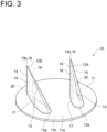
- FIG. 3 is a perspective view of the vortex generator 10 according to an embodiment
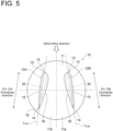
- FIGs. 4 and 5 are each a plan view of the vortex generator according to an embodiment
- FIG. 4 is a plan view of the vortex generator 10 shown in FIG. 3
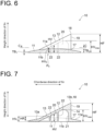
- FIGs. 6 to 9 are each a cross-sectional view of the vortex generator 10 according to an embodiment.
- FIG. 6 is a view showing a cross section taken along line A-A in FIG. 4
- FIG. 7 is a view showing a cross section taken along line B-B in FIG. 4
- FIG. 8 is a view showing a cross section taken along line C-C in FIG. 6
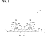
- FIGs. 9 and 10 are each a view showing a cross section taken along line D-D in FIG. 4 .
- FIGs. 9 and 10 are each a view showing the vortex generator together with the wind turbine blade where the vortex generator is attached according to an embodiment.
- the vortex generator 10 includes a platform 11 mounted on a surface of the wind turbine blade 1 (more specifically, a surface of the blade body 2), and at least one fin 12 disposed on the platform 11.
- the platform 11 has an upper surface 11a where the fin 12 is disposed, and a bottom surface 11b opposite to the upper surface 11a.
- the vortex generator 10 is attached to the surface (for example, the suction surface 9) of the blade body 2 via the bottom surface 11b.
- the shape of the platform 11 is not particularly limited, but in some embodiments, the shape of the platform 11 may be circular in plan view as shown in FIGs. 3 to 5 . In some embodiments, the platform 11 may have a shape such as a polygon or an ellipse in plan view. Further, the upper surface 11a of the platform 11 may have a curved shape or may have a planar shape. The upper surface 11a of the platform 11 shown in FIGs.
- the bottom surface 11b of the platform 11 basically has a planar shape, but may not have a perfectly planar shape and may have, for example, a concave curved shape with a relatively large curvature.
- the at least one fin 12 is disposed projecting from the upper surface 11a of the platform 11.
- two fins 12A, 12B are disposed on the platform 11.
- the fins 12A, 12B are collectively referred to as the fin 12.
- the fin 12 has a leading edge 13 located upstream in a wind inflow direction, a trailing edge 14 located downstream in the wind inflow direction, a pressure surface (concave surface) 15 of the fin 12 facing upstream in the wind inflow direction, and a suction surface (convex surface) 16 of the fin 12 facing downstream in the wind inflow direction.
- a direction of straight lines (L CA and L CB in FIGs. 4 and 5 ) each connecting the leading edge 13 and the trailing edge 14 is a chordwise direction of the fin 12.
- the fin 12 extends between a top portion 18 and a base portion 17 connected to the platform 11, in a height direction of the fin 12.
- the height direction of the fin 12 in the present specification is a direction orthogonal to the bottom surface 11b of the platform 11.
- the height direction of the fin 12 is a direction orthogonal to a plane including an edge of the bottom surface 11b of the platform 11.
- the height direction of the fin 12 may simply be referred to as the height direction.
- a height from the bottom surface 11b of the platform 11 means a height from the plane including the edge of the bottom surface 11b of the platform 11, if the bottom surface 11b of the platform does not have the planar shape.
- Separation of a flow on the suction surface 9 of the wind turbine blade 1 is caused by gradually thickening a boundary layer from a streamline flow region in the vicinity of the leading edge 6 toward a turbulent flow region downstream thereof, and separating the flow before arriving at the trailing edge 7.
- the vortex generator 10 attached to the wind turbine blade 1 generates a longitudinal vortex on the suction surface 16 side of the fin 12 with a lift produced by the fin 12. Further, a flow flowing into the fin 12 forms a longitudinal vortex along an edge extending from a most upstream position 13a toward a top portion 13b of the leading edge 13 of the fin 12.
- the longitudinal vortex thus generated by the fin 12 promotes momentum exchange in the height direction of the fin 12 between the inside and the outside of the boundary layer on the wind turbine blade 1 surface, on a wake side of the vortex generator 10.
- the boundary phase on the surface of the wind turbine blade 1 becomes thin, suppressing the separation of the flow from the wind turbine blade 1 surface.
- a leading edge portion 13' is provided which has a curved contour in a cross section orthogonal to the height direction of the fin 12.
- the leading edge portion 13' of the fin 12 has the curved contour in the cross section orthogonal to the height direction, when the vortex generator 10 is installed on the wind turbine blade 1, it is possible to reduce a resistance to the flow of air flowing into the vortex generator 10 and the performance of the vortex generator 10 can easily be exhibited.
- the cross-sectional shape of the fin 12 orthogonal to the height direction of the fin 12 may have an airfoil profile.
- the cross-sectional shape of the fin 12 since the cross-sectional shape of the fin 12 has the airfoil shape, it is possible to effectively suppress the separation of the flow from the wind turbine blade 1 surface.
- the fin 12 has a shape symmetrical with respect to the chord of the fin 12.
- the fin 12 since the fin 12 has the shape symmetrical with respect to the chord of the fin 12, molding, such as injection molding or the like, becomes easier than in a case where the fin 12 has a shape asymmetrical with respect to the chord.
- the fin 12 includes the leading edge portion having the curved contour in the cross section orthogonal to the height direction of the fin, and has the airfoil shape which is symmetrical about the chord of the fin 12 (that is, the pressure surface 15 and the suction surface 16 each have a shape symmetrical about the chord of the fin 12, in the cross section orthogonal to the height direction of the fin 12). Further, in the exemplary embodiment shown in FIG. 4 , the fin 12 includes the leading edge portion having the curved contour in the cross section orthogonal to the height direction of the fin, and has the airfoil shape which is symmetrical about the chord of the fin 12 (that is, the pressure surface 15 and the suction surface 16 each have a shape symmetrical about the chord of the fin 12, in the cross section orthogonal to the height direction of the fin 12). Further, in the exemplary embodiment shown in FIG.
- the fin 12 includes the leading edge portion having the curved contour in the cross section orthogonal to the height direction of the fin, and has the airfoil shape which is asymmetrical about the chord of the fin 12 (that is, the pressure surface 15 and the suction surface 16 each have a shape asymmetrical about the chord of the fin 12, in the cross section orthogonal to the height direction of the fin 12).
- the fin 12 is disposed to be inclined at a predetermined angle with respect to the wind inflow direction.
- each of the fins 12A, 12B may be disposed such that a clearance between the pair of fins 12A, 12B widens from upstream toward downstream in the wind inflow direction (that is, from the leading edge 6 side toward the trailing edge 7 side of the wind turbine blade 1 (see FIG. 2 ).
- each of the fins 12A, 12B may be disposed such that the clearance between the pair of fins 12A, 12B widens from downstream toward upstream in the wind inflow direction (that is, from the trailing edge 7 side toward the leading edge 6 side of the wind turbine blade 1 (see FIG. 2 ).
- a mounting angle (chordwise direction) of the fin 12 is not less than 12 degrees and not greater than 18 degrees with respect to the wind inflow direction.
- the vortex generator 10 (the platform 11 and the fin 12) is made of a resin.
- the resin used as the material of the vortex generator 10 may be a thermoplastic such as ASA (acrylate styrene acrylonitrile), AES (acrylonitrile ethylene styrene), or the like.
- the vortex generator 10 includes cavities 20.
- Each of the cavities 20 is a cavity that opens to the bottom surface 11b of the platform 11 and extends to the inside of the fin 12. That is, the cavity 20 extends, at least partially, over a position range higher than the upper surface 11a of the platform 11, in the height direction of the fin 12.
- the vortex generator 10 since the vortex generator 10 includes the cavity 20 extending to the inside of the fin 12, a wall thickness of the fin 12 relative to a wall thickness of the platform 11 can be reduced compared to a case where the cavity 20 is not provided. That is, according to the above-described embodiments, it is easy to suppress a sink mark due to shrinkage during a cooling process when the vortex generator 10 is molded from the resin material. Thus, it becomes easier to obtain the vortex generator 10 having the shape as designed.
- the vortex generator 10 when the vortex generator 10 is installed on the wind turbine blade 1, it becomes easier to stably bond the vortex generator 10 to the blade body 2 surface, or it becomes easier to obtain as expected the effect of suppressing the separation of the flow from the surface of the wind turbine blade 1 by the vortex generator 10.
- a method for manufacturing the vortex generator 10 is not particularly limited, but the vortex generator 10 may be manufactured by injection molding, for example.
- a method for forming the cavity 20 is not particularly limited, but the cavity 20 may be formed by using a core, for example, during injection molding.
- a maximum value HVmax (see FIG. 6 or 7 ) of a height HV of the cavity 20 from the bottom surface 11b of the platform 11 is not less than HF/3, where HF (see FIG. 6 or 7 ) is a distance between the bottom surface 11b of the platform 11 and the top portion 18 of the fin 12 in the height direction of the fin 12.
- the height HV of the cavity 20 is a distance from the bottom surface 11b of the platform 11 to a surface 21 forming the cavity 20 in the height direction.
- the height HV of the cavity 20 at positions of ribs 22 (see FIGs. 6 to 8 ) described later is defined as the height of the cavity 20 (the distance from the bottom surface 11b of the platform 11 to the surface 21 forming the cavity 20 in the height direction) when it is assumed that the ribs 22 are virtually removed from the vortex generator 10 and the cavity 20 is formed by the continuous smooth surface 21.
- the maximum value HVmax of the height of the cavity 20 from the bottom surface 11b is set to not less than HF/3, an area occupied by the cavity 20 in the fin 12 can relatively be large.
- the maximum value HVmax of the height of the cavity 20 may be not less than HF/2. In this case, it becomes easier to reduce the wall thickness of the fin 12 relative to the wall thickness of the platform 11. Therefore, it is possible to effectively suppress the sink mark due to the shrinkage during the cooling process when the vortex generator 10 is molded, and it becomes easier to obtain the vortex generator 10 having the shape as designed.
- the height HV0 (see FIG. 6 ) of the cavity 20 is not less than a maximum thickness TB 2 (see FIG. 6 ) of the platform 11.
- the thickness of the platform 11 is measured along the height direction of the fin, which is the direction orthogonal to the bottom surface 11b of the platform 11.
- the height of the cavity 20 from the bottom surface 11b at the maximum blade thickness position P 0 of the fin 12 in the chordwise direction of the fin 12 is set to not less than the maximum thickness TB 2 of the platform 11, the area occupied by the cavity 20 in the fin 12 can relatively be large.
- the height HV of the cavity 20 from the bottom surface 11b may be not less than a minimum thickness TB 1 of the platform 11.
- the cavity 20 is disposed in a region including the maximum blade thickness position P 0 (see FIG. 8 ) of the fin 12 in the chordwise direction of the fin 12, and a length LF (see FIG. 8 ) of the cavity 20 in the chordwise direction may be at least 30% of a chord length LF (see FIG. 8 ) of the fin 12.
- the length of the cavity 20 in the chordwise direction may be at least 50% of the fin chord length.
- the blade thickness of the fin 12 is relatively large in the range where the distance from the bottom surface 11b of the platform 11 in the height direction is not less than HF/3 and not greater than HF/5.
- the cavity 20 having the length of at least 30% and at most 50% of the fin chord length is disposed in the region including the maximum blade thickness position P 0 in the chordwise direction within the above-described range (that is, within the range in which the blade thickness of the fin 12 is relatively large) in the height direction of the fin 12, the wall thickness of the fin 12 can effectively be reduced within the said range in the height direction. Therefore, it is possible to effectively suppress the sink mark due to the shrinkage during the cooling process when the vortex generator 10 is molded, and it becomes easier to obtain the vortex generator 10 having the shape as designed.
- a width WV (see FIG. 8 ) of the cavity 20 at the maximum blade thickness position P 0 of the fin 12 in the chordwise direction of the fin 12 is at least 50% of a blade thickness WF (see FIG. 8 ) of the fin 12 at the maximum blade thickness position P 0 .
- the blade thickness of the fin 12 is a size of the fin 12 in the thickness direction of the fin 12 orthogonal to the chordwise direction of the fin 12, and the width of the cavity 20 is a size of the cavity 20 in the thickness direction of the fin 12.
- the cavity 20 has the width WV at the maximum blade thickness position P 0 of the fin 12 in the chordwise direction of the fin 12 which is at least 50% of the blade thickness WF of the fin 12 at the maximum blade thickness position P 0 .
- a wall thickness TV (see FIG. 8 ) of the fin 12 at the position of the leading edge 13 of the fin 12 and in the chordwise direction of the fin 12 is at least 0.5 and at most 2.0 times an average ((TB 1 +TB 2 )/2) of the maximum thickness TB 2 and the minimum thickness TB 1 of the platform 11.
- the wall thickness TV at the position of the leading edge 13 of the fin 12 is at least 0.5 times the average of the maximum thickness TB 2 and the minimum thickness TB 1 of the platform 11 within the range in the height direction described above, it is possible to suppress a decrease in strength of the vortex generator 10 due to the provision of the cavity 20 in the fin 12.
- the wall thickness TV at the position of the leading edge 13 of the fin 12 is at most 2.0 times the average of the maximum thickness TB 2 and the minimum thickness TB 1 of the platform 11 within the range in the height direction described above, the wall thickness TV at the position of the leading edge 13 of the fin 12 is made relatively thin, making it possible to effectively suppress the sink mark due to the shrinkage during the cooling process when the vortex generator 10 is molded.
- the vortex generator 10 having the shape as designed, while suppressing the decrease in strength of the vortex generator.
- the fin 12 may include the leading edge portion 13' having the curved contour in the cross section orthogonal to the height direction. As shown in FIG. 4 , the leading edge portion 13' of the fin 12 having the symmetrical shape with respect to the chord of the fin 12 has the curved contour. Further, as shown in FIG. 5 , the leading edge portion 13' of the fin 12 having the asymmetrical shape with respect to the chord of the fin 12 also has the curved contour.
- the fin 12 may have the airfoil shape.
- the fin 12 may have the shape symmetrical with respect to the chord of the fin 12.
- the fin 12 since the fin 12 has the shape symmetrical with respect to the chord of the fin 12, molding becomes easier than in the case where the fin 12 has the shape asymmetrical with respect to the chord.
- the vortex generator 10 is molded by injection molding, since the fin 12 has the symmetrical shape, the vortex generator 10 is easily removed from a mold.
- the fin 12 may have the shape asymmetrical with respect to the chord of the fin 12.
- the ribs 22 are provided which extend inside the cavity 20 and along the thickness direction of the fin 12.
- the fin 12 is easily deformed toward the thickness direction of the fin 12, resulting in the fin 12 being deformed and the platform 11 also easily being deformed along the thickness direction of the fin 12.
- the ribs 22 extending along the thickness direction of the fin 12 are disposed inside the cavity 20, it is possible to suppress the deformation in the fin 12 in the thickness direction of the fin 12.
- the ribs 22 may integrally be formed with the vortex generator 10 having the cavity 20, such as by injection molding. Alternatively, the ribs 22 may be installed inside the cavity 20 after the fin 12 of the vortex generator 10 having the cavity 20 is molded.
- At least one or two ribs 22 may be disposed in the cavity 20.
- the two ribs are respectively disposed at positions spaced apart from each other in the chordwise direction of the fin 12.
- the ribs 22 extend along the height direction of the fin 12 over at least 70% of the extension range of the cavity 20 in the height direction of the fin 12.
- a height HR (see FIG. 7 ) of the rib 22 is set at at least 70% of the extension range of the cavity 20 in the height direction of the fin 12 (a height HV 1 of the cavity 20 at the position of the rib 22). That is, since the rib 22 extends along the height direction of the fin 12 over at least 70% of the extension range of the cavity 20 in the height direction of the fin 12, it is possible to effectively suppress the deformation in the fin 12 in the thickness direction of the fin 12. Thus, it is also possible to effectively suppress the deformation in the platform 11 associated with the deformation in the fin 12. Therefore, it becomes much easier to obtain the vortex generator 10 having the shape as designed.
- the height HR of the rib 22 is the length of the rib 22 in the height direction of the fin 12.
- At least one of the ribs 22 is disposed at a position where the distance from the leading edge 13 in the chordwise direction of the fin 12 is not greater than LF/2 (half the chord length), at the position where the distance from the bottom surface 11b of the platform 11 in the height direction of the fin 12 is the maximum thickness of the platform 11.
- the rib 22 is disposed in the region on the leading edge side where the blade thickness of the fin 12 is relatively large, it is possible to effectively suppress the deformation in the platform 11 associated with the deformation in the fin 12. Therefore, it becomes much easier to obtain the vortex generator 10 having the shape as designed.
- the vortex generator 10 includes a hole 24 which is disposed in the fin 12 and communicates with the cavity 20 as well as opens to the surface (the suction surface 16 in FIGs. 9 and 10 ) of the fin.
- the hole 24 is a hole which opens to the fin 12 surface on one end side and opens to the surface 21 forming the cavity 20 on another end side.
- the fin 12 since the fin 12 includes the hole 24 which communicates with the cavity 20 and opens to the surface of the fin 12, for example, by connecting an air suction device (not shown) to the hole 24, air in cavity 20 can be evacuated via the hole 24. By evacuating the air in the cavity 20 via the hole 24, a pressing force against the wind turbine blade 1 can be applied to the vortex generator 10, making it possible to easily attach the vortex generator to the wind turbine blade 1.
- the hole 24 is disposed in the suction surface 16 of the fin 12.
- the hole 24 may be disposed in the pressure surface 15 of fin 12. In this case, processing work for forming the hole 24 is performed easily.
- the hole 24 may be disposed in a rear end surface 19 (see FIGs. 4 and 8 ) including the trailing edge 14 of fin 12. In this case, it is possible to suppress deterioration in aerodynamic performance of the vortex generator 10 due to providing the hole in the fin 12.
- the vortex generator 10 may be adhered to the blade body 2 with an adhesive material 30 (for example, a double-sided tape, an adhesive agent, or the like).
- an adhesive material 30 for example, a double-sided tape, an adhesive agent, or the like.
- a step Z is generated between the platform 11 and the surface of the blade body 2. Therefore, as shown in FIG. 10 , a tape 32 may be adhered to the upper surface 11a of the platform 11 in the vortex generator 10 and the surface of the blade body 2 so as to cover an edge 11c of the platform 11.
- the wind turbine blade 1 includes the tape 32 which has an adhesive surface 32a adhered to the upper surface 11a of the platform 11 in the vortex generator 10 and the surface (for example, the suction surface 9) of the blade body 2 so as to cover the edge 11c of the platform 11.
- the vortex generator 10 is adhered to the surface (for example, the suction surface 9) of the blade body 2.
- the bottom surface 11b of the vortex generator 10 and the surface of the blade body 2 are adhered with the adhesive material 30 (the double-sided tape, the adhesive agent, or the like).
- the tape 32 is applied to the upper surface 11a of the platform 11 in the vortex generator 10 and the surface of the blade body 2 so as to cover the edge 11c of the platform 11.
- the internal air of the cavity 20 is sucked via the hole 24 of the vortex generator 10.
- This operation is performed by, for example, connecting the air suction device to the hole 24.
- a sufficient pressing force can easily be applied to the vortex generator 10 when the vortex generator 10 is attached to the blade body 2.
- the vortex generator 10 can appropriately be attached to the blade body 2 with easy construction work.
- the pressing force can easily be applied to the vortex generator 10 adhered to the surface of the blade body 2.
- a height (HV) of the cavity from the bottom surface is not less than the maximum thickness (TB 2 ) of the platform.
- the height of the cavity from the bottom surface at the maximum blade thickness position of the fin in the chordwise direction of the fin is set to not less than the maximum thickness of the platform, the area occupied by the cavity in the fin can relatively be large.
- the cavity is disposed in a region including a maximum blade thickness position of the fin in a chordwise direction of the fin, and a length (LV) of the cavity in the chordwise direction is at least 30% of a chord length (LF) of the fin.
- the blade thickness of the fin 12 is relatively large in the range where the distance from the bottom surface of the platform in the height direction of the fin is not greater than HF/3.
- the cavity is disposed in the region including the maximum blade thickness position of the fin in the chordwise direction of the fin, and the length of the cavity in the chordwise direction is at least 30% of the chord length of the fin.
- a width (WV) of the cavity at a maximum blade thickness position of the fin in a chordwise direction of the fin is at least 50% of a blade thickness (WF) of the fin at the maximum blade thickness position.
- the width of the cavity at the maximum blade thickness position of the fin in the chordwise direction of the fin is at least 50% of the blade thickness of the fin at the maximum blade thickness position.
- a wall thickness (TV) of the fin at a position of a leading edge of the fin and in a chordwise direction of the fin is at least 0.5 and at most 2.0 times an average of a maximum thickness (TB 2 ) and a minimum thickness (TB 1 ) of the platform.
- the wall thickness of the fin described above is at least 0.5 times the average of the maximum thickness and the minimum thickness of the platform, it is possible to suppress a decrease in strength of the vortex generator due to the provision of the cavity in the fin. Further, in the above configuration (6), since the wall thickness of the fin described above is at most 2.0 times the average of the maximum thickness and the minimum thickness of the platform, the wall thickness in the leading edge portion of the fin is made relatively thin, making it possible to effectively suppress the sink mark due to the shrinkage during the cooling process when the vortex generator is molded. Thus, with the above configuration (6), it is possible to obtain the vortex generator having the shape as designed, while suppressing the decrease in strength of the vortex generator.
- the fin in the above configurations (1) to (6), includes a leading edge portion (13') having a curved contour in a cross section orthogonal to the height direction.
- the leading edge portion of the fin has the curved contour in the cross section orthogonal to the height direction, when the vortex generator is installed on the wind turbine blade, it is possible to reduce a resistance to the flow of air flowing into the vortex generator and the performance of the vortex generator can easily be exhibited.
- the fin has a shape symmetrical with respect to a chord of the fin.
- the vortex generator can be molded easily compared to the case where the fin has the shape asymmetrical with respect to the chord.
- the vortex generator for wind turbine blade includes: a rib (22) extending inside the cavity and along a thickness direction of the fin.
- the rib in the above configurations (1) to (9), the rib extends along a height direction of the fin over at least 70% of an extension range of the cavity in the height direction of the fin.
- the vortex generator for wind turbine includes: a hole (24) disposed in the fin, and communicating with the cavity as well as opening to a surface of the fin.
- the fin since the fin includes the hole which communicates with the cavity and opens to the surface of the fin, air in cavity can be evacuated via the hole. Therefore, by evacuating the air in the cavity via the hole, a pressing force against the wind turbine blade can be applied to the vortex generator, making it possible to easily attach the vortex generator to the wind turbine blade.
- a wind turbine blade (1) includes: a blade body (2); and the vortex generator (10) according to any one of the above (1) to (11) attached to a surface of the blade body.
- the vortex generator since the vortex generator includes the cavity extending to the inside of the fin, the wall thickness of the fin relative to the wall thickness of the platform can be reduced. That is, with the above configuration (12), it is easy to suppress the sink mark due to the shrinkage during the cooling process when the vortex generator is molded from the resin material. Thus, it becomes easier to obtain the vortex generator having the shape as designed.
- the wind turbine blade includes: a tape (32) which has an adhesive surface (32a) adhered to the upper surface (11a) of the platform (11) in the vortex generator and the surface (for example, the suction surface 9) of the blade body so as to cover an edge (11c) of the platform.
- a wind power generating apparatus (40) includes: a wind turbine rotor (42) including the wind turbine blade according to the above (12) or (13); and a generator configured to be driven by the wind turbine rotor.
- the vortex generator since the vortex generator includes the cavity extending to the inside of the fin, the wall thickness of the fin relative to the wall thickness of the platform can be reduced. That is, with the above configuration (14), it is easy to suppress the sink mark due to the shrinkage during the cooling process when the vortex generator is molded from the resin material. Thus, it becomes easier to obtain the vortex generator having the shape as designed.
- a method for manufacturing a wind turbine blade according to at least one embodiment of the present invention is a method for manufacturing a wind turbine blade (1) including a blade body (1) and the vortex generator (10) according to the above (11), including: a step of adhering the vortex generator to a surface (for example, the suction surface 9) of the blade body; and a step of sucking internal air of the cavity (20) via the hole (24).
- Embodiments of the present invention were described in detail above, but the present invention is not limited thereto, and also includes an embodiment obtained by modifying the above-described embodiments and an embodiment obtained by combining these embodiments as appropriate.
- an expression of relative or absolute arrangement such as “in a direction”, “along a direction”, “parallel”, “orthogonal”, “centered”, “concentric” and “coaxial” shall not be construed as indicating only the arrangement in a strict literal sense, but also includes a state where the arrangement is relatively displaced by a tolerance, or by an angle or a distance whereby it is possible to achieve the same function.
- an expression of an equal state such as “same” “equal” and “uniform” shall not be construed as indicating only the state in which the feature is strictly equal, but also includes a state in which there is a tolerance or a difference that can still achieve the same function.
- an expression of a shape such as a rectangular shape or a cylindrical shape shall not be construed as only the geometrically strict shape, but also includes a shape with unevenness or chamfered corners within the range in which the same effect can be achieved.
Landscapes
- Engineering & Computer Science (AREA)
- Mechanical Engineering (AREA)
- Physics & Mathematics (AREA)
- Fluid Mechanics (AREA)
- Life Sciences & Earth Sciences (AREA)
- Sustainable Development (AREA)
- Sustainable Energy (AREA)
- Chemical & Material Sciences (AREA)
- Combustion & Propulsion (AREA)
- General Engineering & Computer Science (AREA)
- Wind Motors (AREA)
- Lining Or Joining Of Plastics Or The Like (AREA)
Abstract
Description
- The present disclosure relates to a vortex generator for wind turbine blade, a wind turbine blade and a wind power generating apparatus, and a method for manufacturing the wind turbine blade.
- This application claims the priority of
Japanese Patent Application No. 2020-197391 filed on November 27, 2020 - Conventionally, approaches to improve aerodynamic performance of a wind turbine blade have been sought with the object of improving operation efficiency of a wind turbine. In one of the approaches, a vortex generator is disposed on a surface of the wind turbine blade to suppress separation of a flow along the surface of the wind turbine blade.
-
Patent Documents 1 to 8 disclose a vortex generator which includes a platform mounted on a surface of a wind turbine blade, and a fin disposed upright on the platform. -
- Patent Document 1:
EP2484898A - Patent Document 2:
WO2015/030573A - Patent Document 3:
DE102013201871A - Patent Document 4:
WO2014/198353A - Patent Document 5:
EP2824320A - Patent Document 6:
EP2739529A - Patent Document 7:
WO2006/122547A - Patent Document 8:
EP2736805A - Meanwhile, a vortex generator tends to increase in size as a wind turbine blade increases in size, and a wall thickness of a fin tends to increase. Thus, a sink mark due to shrinkage occurs during a cooling process when the vortex generator is molded, and distortion or a dent is likely to occur. In this case, a vortex generator having a shape as designed cannot be obtained and when this vortex generator is installed on a wind turbine blade, an expected function or performance may not be obtained.
- In view of the above, an object of at least one embodiment of the present invention is to provide the vortex generator for wind turbine blade where the vortex generator having the shape as designed is easily obtained, the wind turbine blade and the wind power generating apparatus, and the method for manufacturing the wind turbine blade.
- A vortex generator for wind turbine blade according to at least one embodiment of the present invention is a vortex generator for wind turbine blade, the vortex generator being made of a resin, including: a platform; and at least one fin disposed projecting from an upper surface of the platform. The vortex generator includes a cavity that opens to a bottom surface of the platform and extends to an inside of the fin.
- A wind turbine blade according to at least one embodiment of the present invention, includes: a blade body; and the above-described vortex generator attached to a surface of the blade body.
- A wind power generating apparatus according to at least one embodiment of the present invention, includes: a wind turbine rotor including the above-described wind turbine blade; and a generator configured to be driven by the wind turbine rotor.
- A method for manufacturing a wind turbine blade according to at least one embodiment of the present invention is a method for manufacturing a wind turbine blade including a blade body, and the above-described vortex generator which includes a hole disposed in the fin, and communicating with the cavity as well as opening to a surface of the fin, including: a step of adhering the vortex generator to a surface of the blade body; and a step of sucking internal air of the cavity via the hole.
- According to at least one embodiment of the present invention, provided are a vortex generator for a wind turbine blade where a vortex generator having a shape as designed is easily obtained, a wind turbine blade and a wind power generating apparatus, and a method for manufacturing the wind turbine blade.
-
-
FIG. 1 is a schematic configuration view of a wind power generating apparatus according to an embodiment. -
FIG. 2 is a perspective view of a wind turbine blade according to an embodiment. -
FIG. 3 is a perspective view of a vortex generator according to an embodiment. -
FIG. 4 is a plan view of the vortex generator shown inFIG. 3 . -
FIG. 5 is a plan view of the vortex generator according to an embodiment. -
FIG. 6 is a view showing a cross section taken along line A-A inFIG. 4 . -
FIG. 7 is a view showing a cross section taken along line B-B inFIG. 4 . -
FIG. 8 is a view showing a cross section taken along line C-C inFIG. 6 . -
FIG. 9 is a view showing an example of a cross section taken along line D-D inFIG. 4 . -
FIG. 10 is a view showing an example of the cross section taken along line D-D inFIG. 4 . - Some embodiments of the present invention will be described below with reference to the accompanying drawings. It is intended, however, that unless particularly identified, dimensions, materials, shapes, relative positions and the like of components described or shown in the drawings as the embodiments shall be interpreted as illustrative only and not intended to limit the scope of the present invention.
- First, with reference to
FIGs. 1 and2 , the overall configuration of a wind power generating apparatus and a wind turbine blade to which a vortex generator is applied according to some embodiments will be described.FIG. 1 is a schematic configuration view of the wind power generating apparatus according to an embodiment, andFIG. 2 is a perspective view of the wind turbine blade according to an embodiment. - As shown in
FIG. 1 , a windpower generating apparatus 40 includes arotor 42 composed of at least one (for example, three)wind turbine blade 1 and ahub 43. It is configured such that thewind turbine blade 1 is radially mounted on thehub 43, therotor 42 is rotated by receiving wind with thewind turbine blade 1, and electricity is generated by a generator (not shown) connected to therotor 42. - In the embodiment shown in
FIG. 1 , therotor 42 is supported by anacelle 44 disposed on an upper side of atower 46. Further, thetower 46 is disposed upright on a base structure 48 (a foundation structure, a floating structure, or the like) disposed on water or on land. - As described below, a vortex generator according to an embodiment is attached to the
wind turbine blade 1 of the windpower generating apparatus 40. - As shown in
FIG. 2 , thewind turbine blade 1 includes ablade body 2, andvortex generators 10 disposed on the surface of the blade body 2 (blade surface). - The
blade body 2 includes ablade root 3 mounted on thehub 43 of the windpower generating apparatus 40, ablade tip 4 located farthest from thehub 43, and anairfoil portion 5 extending between theblade root 3 and theblade tip 4. Further, thewind turbine blade 1 has a leadingedge 6 and atrailing edge 7 from theblade root 3 to theblade tip 4. Furthermore, an exterior shape of thewind turbine blade 1 is formed by a pressure surface (concave surface) 8 and a suction surface (convex surface) 9 disposed opposite to thepressure surface 8. - In the
wind turbine blade 1 shown inFIG. 2 , the plurality of thevortex generators 10 are attached to thesuction surface 9 of theblade body 2. Further, the plurality ofvortex generators 10 are arranged on thesuction surface 9 of theblade body 2 in a blade spanwise direction. - Hereinafter, in the present specification, the "blade spanwise direction" refers to a direction connecting the
blade root 3 and theblade tip 4. - Next, the
vortex generator 10 according to some embodiments will be described in detail with reference toFIGs. 3 to 10 . -
FIG. 3 is a perspective view of thevortex generator 10 according to an embodiment, andFIGs. 4 and5 are each a plan view of the vortex generator according to an embodiment.FIG. 4 is a plan view of thevortex generator 10 shown inFIG. 3 .FIGs. 6 to 9 are each a cross-sectional view of thevortex generator 10 according to an embodiment.FIG. 6 is a view showing a cross section taken along line A-A inFIG. 4 ,FIG. 7 is a view showing a cross section taken along line B-B inFIG. 4 ,FIG. 8 is a view showing a cross section taken along line C-C inFIG. 6 , andFIGs. 9 and10 are each a view showing a cross section taken along line D-D inFIG. 4 . Further,FIGs. 9 and10 are each a view showing the vortex generator together with the wind turbine blade where the vortex generator is attached according to an embodiment. - As shown in
FIGs. 3 to 5 , thevortex generator 10 includes aplatform 11 mounted on a surface of the wind turbine blade 1 (more specifically, a surface of the blade body 2), and at least onefin 12 disposed on theplatform 11. - The
platform 11 has anupper surface 11a where thefin 12 is disposed, and abottom surface 11b opposite to theupper surface 11a. Thevortex generator 10 is attached to the surface (for example, the suction surface 9) of theblade body 2 via thebottom surface 11b. The shape of theplatform 11 is not particularly limited, but in some embodiments, the shape of theplatform 11 may be circular in plan view as shown inFIGs. 3 to 5 . In some embodiments, theplatform 11 may have a shape such as a polygon or an ellipse in plan view. Further, theupper surface 11a of theplatform 11 may have a curved shape or may have a planar shape. Theupper surface 11a of theplatform 11 shown inFIGs. 6 and 7 has a convex curved shape projecting in a direction from thebottom surface 11b toward theupper surface 11a. Thebottom surface 11b of theplatform 11 basically has a planar shape, but may not have a perfectly planar shape and may have, for example, a concave curved shape with a relatively large curvature. - The at least one
fin 12 is disposed projecting from theupper surface 11a of theplatform 11. In the illustrated embodiment, twofins platform 11. Hereinafter, thefins fin 12. - As shown in
FIGs. 3 to 5 , thefin 12 has aleading edge 13 located upstream in a wind inflow direction, a trailingedge 14 located downstream in the wind inflow direction, a pressure surface (concave surface) 15 of thefin 12 facing upstream in the wind inflow direction, and a suction surface (convex surface) 16 of thefin 12 facing downstream in the wind inflow direction. In thefin 12, a direction of straight lines (LCA and LCB inFIGs. 4 and5 ) each connecting the leadingedge 13 and the trailingedge 14 is a chordwise direction of thefin 12. Further, thefin 12 extends between atop portion 18 and abase portion 17 connected to theplatform 11, in a height direction of thefin 12. - The height direction of the
fin 12 in the present specification is a direction orthogonal to thebottom surface 11b of theplatform 11. Alternatively, if thebottom surface 11b of the platform does not have a planar shape, the height direction of thefin 12 is a direction orthogonal to a plane including an edge of thebottom surface 11b of theplatform 11. Hereinafter, the height direction of thefin 12 may simply be referred to as the height direction. Further, in the following description, a height from thebottom surface 11b of theplatform 11 means a height from the plane including the edge of thebottom surface 11b of theplatform 11, if thebottom surface 11b of the platform does not have the planar shape. - Herein, the effect of the
vortex generator 10 will briefly be described. - Separation of a flow on the
suction surface 9 of thewind turbine blade 1 is caused by gradually thickening a boundary layer from a streamline flow region in the vicinity of theleading edge 6 toward a turbulent flow region downstream thereof, and separating the flow before arriving at the trailingedge 7. - The
vortex generator 10 attached to thewind turbine blade 1 generates a longitudinal vortex on thesuction surface 16 side of thefin 12 with a lift produced by thefin 12. Further, a flow flowing into thefin 12 forms a longitudinal vortex along an edge extending from a mostupstream position 13a toward atop portion 13b of the leadingedge 13 of thefin 12. The longitudinal vortex thus generated by thefin 12 promotes momentum exchange in the height direction of thefin 12 between the inside and the outside of the boundary layer on thewind turbine blade 1 surface, on a wake side of thevortex generator 10. Thus, the boundary phase on the surface of thewind turbine blade 1 becomes thin, suppressing the separation of the flow from thewind turbine blade 1 surface. - In some embodiments, for example, as shown in
FIGs. 4 and5 , a leading edge portion 13' is provided which has a curved contour in a cross section orthogonal to the height direction of thefin 12. - According to the above-described embodiments, since the leading edge portion 13' of the
fin 12 has the curved contour in the cross section orthogonal to the height direction, when thevortex generator 10 is installed on thewind turbine blade 1, it is possible to reduce a resistance to the flow of air flowing into thevortex generator 10 and the performance of thevortex generator 10 can easily be exhibited. - In some embodiments, for example, as shown in
FIGs. 4 and5 , the cross-sectional shape of thefin 12 orthogonal to the height direction of thefin 12 may have an airfoil profile. - In the above-described embodiments, since the cross-sectional shape of the
fin 12 has the airfoil shape, it is possible to effectively suppress the separation of the flow from thewind turbine blade 1 surface. - In some embodiments, for example, as shown in
FIG. 4 , thefin 12 has a shape symmetrical with respect to the chord of thefin 12. - According to the above-described embodiments, since the
fin 12 has the shape symmetrical with respect to the chord of thefin 12, molding, such as injection molding or the like, becomes easier than in a case where thefin 12 has a shape asymmetrical with respect to the chord. - In the exemplary embodiment shown in
FIG. 4 , thefin 12 includes the leading edge portion having the curved contour in the cross section orthogonal to the height direction of the fin, and has the airfoil shape which is symmetrical about the chord of the fin 12 (that is, thepressure surface 15 and thesuction surface 16 each have a shape symmetrical about the chord of thefin 12, in the cross section orthogonal to the height direction of the fin 12). Further, in the exemplary embodiment shown inFIG. 5 , thefin 12 includes the leading edge portion having the curved contour in the cross section orthogonal to the height direction of the fin, and has the airfoil shape which is asymmetrical about the chord of the fin 12 (that is, thepressure surface 15 and thesuction surface 16 each have a shape asymmetrical about the chord of thefin 12, in the cross section orthogonal to the height direction of the fin 12). - In some embodiments, the
fin 12 is disposed to be inclined at a predetermined angle with respect to the wind inflow direction. In some embodiments, as shown inFIGs. 3 to 5 , each of thefins fins leading edge 6 side toward the trailingedge 7 side of the wind turbine blade 1 (seeFIG. 2 ). In some embodiments, each of thefins fins edge 7 side toward theleading edge 6 side of the wind turbine blade 1 (seeFIG. 2 ). - In some embodiments, a mounting angle (chordwise direction) of the fin 12 (the
fin 12A and/or thefin 12B) is not less than 12 degrees and not greater than 18 degrees with respect to the wind inflow direction. By attaching thevortex generator 10 havingsuch fin 12 to thewind turbine blade 1, it is possible to effectively suppress the separation of the flow from thewind turbine blade 1 surface. - In some embodiments, the vortex generator 10 (the
platform 11 and the fin 12) is made of a resin. The resin used as the material of thevortex generator 10 may be a thermoplastic such as ASA (acrylate styrene acrylonitrile), AES (acrylonitrile ethylene styrene), or the like. - As shown in
FIGs. 3 to 5 , thevortex generator 10 includescavities 20. Each of thecavities 20 is a cavity that opens to thebottom surface 11b of theplatform 11 and extends to the inside of thefin 12. That is, thecavity 20 extends, at least partially, over a position range higher than theupper surface 11a of theplatform 11, in the height direction of thefin 12. - According to the above-described embodiments, since the
vortex generator 10 includes thecavity 20 extending to the inside of thefin 12, a wall thickness of thefin 12 relative to a wall thickness of theplatform 11 can be reduced compared to a case where thecavity 20 is not provided. That is, according to the above-described embodiments, it is easy to suppress a sink mark due to shrinkage during a cooling process when thevortex generator 10 is molded from the resin material. Thus, it becomes easier to obtain thevortex generator 10 having the shape as designed. Therefore, for example, when thevortex generator 10 is installed on thewind turbine blade 1, it becomes easier to stably bond thevortex generator 10 to theblade body 2 surface, or it becomes easier to obtain as expected the effect of suppressing the separation of the flow from the surface of thewind turbine blade 1 by thevortex generator 10. - A method for manufacturing the
vortex generator 10 is not particularly limited, but thevortex generator 10 may be manufactured by injection molding, for example. A method for forming thecavity 20 is not particularly limited, but thecavity 20 may be formed by using a core, for example, during injection molding. - In some embodiments, in the
cavity 20, a maximum value HVmax (seeFIG. 6 or 7 ) of a height HV of thecavity 20 from thebottom surface 11b of theplatform 11 is not less than HF/3, where HF (seeFIG. 6 or 7 ) is a distance between thebottom surface 11b of theplatform 11 and thetop portion 18 of thefin 12 in the height direction of thefin 12. The height HV of thecavity 20 is a distance from thebottom surface 11b of theplatform 11 to asurface 21 forming thecavity 20 in the height direction. - The height HV of the
cavity 20 at positions of ribs 22 (seeFIGs. 6 to 8 ) described later is defined as the height of the cavity 20 (the distance from thebottom surface 11b of theplatform 11 to thesurface 21 forming thecavity 20 in the height direction) when it is assumed that theribs 22 are virtually removed from thevortex generator 10 and thecavity 20 is formed by the continuoussmooth surface 21. - According to the above-described embodiments, since the maximum value HVmax of the height of the
cavity 20 from thebottom surface 11b is set to not less than HF/3, an area occupied by thecavity 20 in thefin 12 can relatively be large. Thus, it becomes easier to reduce the wall thickness of thefin 12 relative to the wall thickness of theplatform 11. Therefore, it is possible to effectively suppress the sink mark due to the shrinkage during the cooling process when thevortex generator 10 is molded, and it becomes easier to obtain thevortex generator 10 having the shape as designed. - The maximum value HVmax of the height of the
cavity 20 may be not less than HF/2. In this case, it becomes easier to reduce the wall thickness of thefin 12 relative to the wall thickness of theplatform 11. Therefore, it is possible to effectively suppress the sink mark due to the shrinkage during the cooling process when thevortex generator 10 is molded, and it becomes easier to obtain thevortex generator 10 having the shape as designed. - In some embodiments, at a maximum blade thickness position P0 (see
FIG. 6 ) of thefin 12 in the chordwise direction of thefin 12 and at a position where the distance from thebottom surface 11b of theplatform 11 is the maximum thickness of theplatform 11 in the height direction of thefin 12, the height HV0 (seeFIG. 6 ) of thecavity 20 is not less than a maximum thickness TB2 (seeFIG. 6 ) of theplatform 11. However, the thickness of theplatform 11 is measured along the height direction of the fin, which is the direction orthogonal to thebottom surface 11b of theplatform 11. - According to the above-described embodiments, since the height of the
cavity 20 from thebottom surface 11b at the maximum blade thickness position P0 of thefin 12 in the chordwise direction of thefin 12 is set to not less than the maximum thickness TB2 of theplatform 11, the area occupied by thecavity 20 in thefin 12 can relatively be large. Thus, it becomes easier to reduce the wall thickness of thefin 12 relative to the wall thickness of theplatform 11. Therefore, it is possible to effectively suppress the sink mark due to the shrinkage during the cooling process when thevortex generator 10 is molded, and it becomes easier to obtain thevortex generator 10 having the shape as designed. Further, the height HV of thecavity 20 from thebottom surface 11b may be not less than a minimum thickness TB1 of theplatform 11. - In some embodiments, within a range where the distance from the
bottom surface 11b of theplatform 11 in the height direction is not less than the maximum thickness TB2 of theplatform 11 and not greater than HF/3, thecavity 20 is disposed in a region including the maximum blade thickness position P0 (seeFIG. 8 ) of thefin 12 in the chordwise direction of thefin 12, and a length LF (seeFIG. 8 ) of thecavity 20 in the chordwise direction may be at least 30% of a chord length LF (seeFIG. 8 ) of thefin 12. - Alternatively, in some embodiments, within a range where the height HV of the
cavity 20 in the height direction from thebottom surface 11b is not less than the maximum thickness of theplatform 11 and not greater than HF/5, the length of thecavity 20 in the chordwise direction may be at least 50% of the fin chord length. - The blade thickness of the
fin 12 is relatively large in the range where the distance from thebottom surface 11b of theplatform 11 in the height direction is not less than HF/3 and not greater than HF/5. In this regard, in the above-described embodiments, since thecavity 20 having the length of at least 30% and at most 50% of the fin chord length is disposed in the region including the maximum blade thickness position P0 in the chordwise direction within the above-described range (that is, within the range in which the blade thickness of thefin 12 is relatively large) in the height direction of thefin 12, the wall thickness of thefin 12 can effectively be reduced within the said range in the height direction. Therefore, it is possible to effectively suppress the sink mark due to the shrinkage during the cooling process when thevortex generator 10 is molded, and it becomes easier to obtain thevortex generator 10 having the shape as designed. - In some embodiments, within a range where the distance from the
bottom surface 11b of theplatform 11 in the height direction is not less than the maximum thickness TB2 of theplatform 11 and not greater than HF/5, a width WV (seeFIG. 8 ) of thecavity 20 at the maximum blade thickness position P0 of thefin 12 in the chordwise direction of thefin 12 is at least 50% of a blade thickness WF (seeFIG. 8 ) of thefin 12 at the maximum blade thickness position P0. - The blade thickness of the
fin 12 is a size of thefin 12 in the thickness direction of thefin 12 orthogonal to the chordwise direction of thefin 12, and the width of thecavity 20 is a size of thecavity 20 in the thickness direction of thefin 12. - According to the above-described embodiments, within the range where the distance from the
bottom surface 11b in the height direction is not less than the maximum thickness TB2 of theplatform 11 and not greater than HF/5, thecavity 20 has the width WV at the maximum blade thickness position P0 of thefin 12 in the chordwise direction of thefin 12 which is at least 50% of the blade thickness WF of thefin 12 at the maximum blade thickness position P0. Thus, it is easy to reduce the wall thickness of thefin 12 at the maximum blade thickness position P0 of thefin 12, within the above-described range in the height direction. Therefore, it is possible to effectively suppress the sink mark due to the shrinkage during the cooling process when thevortex generator 10 is molded, and it becomes much easier to obtain thevortex generator 10 having the shape as designed. - In some embodiments, in at least 50% of an extension range of the
cavity 20 in the height direction of thefin 12, a wall thickness TV (seeFIG. 8 ) of thefin 12 at the position of the leadingedge 13 of thefin 12 and in the chordwise direction of thefin 12 is at least 0.5 and at most 2.0 times an average ((TB1+TB2)/2) of the maximum thickness TB2 and the minimum thickness TB1 of theplatform 11. - In the above-described embodiments, since the wall thickness TV at the position of the leading
edge 13 of thefin 12 is at least 0.5 times the average of the maximum thickness TB2 and the minimum thickness TB1 of theplatform 11 within the range in the height direction described above, it is possible to suppress a decrease in strength of thevortex generator 10 due to the provision of thecavity 20 in thefin 12. Further, since the wall thickness TV at the position of the leadingedge 13 of thefin 12 is at most 2.0 times the average of the maximum thickness TB2 and the minimum thickness TB1 of theplatform 11 within the range in the height direction described above, the wall thickness TV at the position of the leadingedge 13 of thefin 12 is made relatively thin, making it possible to effectively suppress the sink mark due to the shrinkage during the cooling process when thevortex generator 10 is molded. Thus, it is possible to obtain thevortex generator 10 having the shape as designed, while suppressing the decrease in strength of the vortex generator. - In an embodiment, as already described, the
fin 12 may include the leading edge portion 13' having the curved contour in the cross section orthogonal to the height direction. As shown inFIG. 4 , the leading edge portion 13' of thefin 12 having the symmetrical shape with respect to the chord of thefin 12 has the curved contour. Further, as shown inFIG. 5 , the leading edge portion 13' of thefin 12 having the asymmetrical shape with respect to the chord of thefin 12 also has the curved contour. - According to the above-described embodiment, when the
vortex generator 10 is installed on thewind turbine blade 1, it is possible to reduce the resistance to the flow of air flowing into thevortex generator 10 and the performance of thevortex generator 10 can easily be exhibited. Thefin 12 may have the airfoil shape. - In an embodiment, as shown in
FIG. 4 , thefin 12 may have the shape symmetrical with respect to the chord of thefin 12. - According to the above-described embodiment, since the
fin 12 has the shape symmetrical with respect to the chord of thefin 12, molding becomes easier than in the case where thefin 12 has the shape asymmetrical with respect to the chord. For example, if thevortex generator 10 is molded by injection molding, since thefin 12 has the symmetrical shape, thevortex generator 10 is easily removed from a mold. - In some embodiments, as shown in
FIG. 5 , thefin 12 may have the shape asymmetrical with respect to the chord of thefin 12. - As shown in
FIGs. 6 to 8 , in an embodiment, theribs 22 are provided which extend inside thecavity 20 and along the thickness direction of thefin 12. - If the
cavity 20 is disposed inside thefin 12, thefin 12 is easily deformed toward the thickness direction of thefin 12, resulting in thefin 12 being deformed and theplatform 11 also easily being deformed along the thickness direction of thefin 12. In this regard, according to the above-described embodiment, since theribs 22 extending along the thickness direction of thefin 12 are disposed inside thecavity 20, it is possible to suppress the deformation in thefin 12 in the thickness direction of thefin 12. Thus, it is also possible to suppress the deformation in theplatform 11 associated with the deformation in thefin 12 described above. Therefore, it becomes much easier to obtain thevortex generator 10 having the shape as designed. - The
ribs 22 may integrally be formed with thevortex generator 10 having thecavity 20, such as by injection molding. Alternatively, theribs 22 may be installed inside thecavity 20 after thefin 12 of thevortex generator 10 having thecavity 20 is molded. - At least one or two
ribs 22 may be disposed in thecavity 20. In the exemplary embodiments shown inFIGs. 6 to 8 , in thecavity 20, the two ribs are respectively disposed at positions spaced apart from each other in the chordwise direction of thefin 12. - In some embodiments, the
ribs 22 extend along the height direction of thefin 12 over at least 70% of the extension range of thecavity 20 in the height direction of thefin 12. - In the above-described embodiments, a height HR (see
FIG. 7 ) of therib 22 is set at at least 70% of the extension range of thecavity 20 in the height direction of the fin 12 (a height HV1 of thecavity 20 at the position of the rib 22). That is, since therib 22 extends along the height direction of thefin 12 over at least 70% of the extension range of thecavity 20 in the height direction of thefin 12, it is possible to effectively suppress the deformation in thefin 12 in the thickness direction of thefin 12. Thus, it is also possible to effectively suppress the deformation in theplatform 11 associated with the deformation in thefin 12. Therefore, it becomes much easier to obtain thevortex generator 10 having the shape as designed. The height HR of therib 22 is the length of therib 22 in the height direction of thefin 12. - In some embodiments, at least one of the
ribs 22 is disposed at a position where the distance from the leadingedge 13 in the chordwise direction of thefin 12 is not greater than LF/2 (half the chord length), at the position where the distance from thebottom surface 11b of theplatform 11 in the height direction of thefin 12 is the maximum thickness of theplatform 11. - According to the above-described embodiments, since the
rib 22 is disposed in the region on the leading edge side where the blade thickness of thefin 12 is relatively large, it is possible to effectively suppress the deformation in theplatform 11 associated with the deformation in thefin 12. Therefore, it becomes much easier to obtain thevortex generator 10 having the shape as designed. - In some embodiments, for example, as shown in
FIGs. 9 and10 , thevortex generator 10 includes ahole 24 which is disposed in thefin 12 and communicates with thecavity 20 as well as opens to the surface (thesuction surface 16 inFIGs. 9 and10 ) of the fin. Thehole 24 is a hole which opens to thefin 12 surface on one end side and opens to thesurface 21 forming thecavity 20 on another end side. - According to the above-described embodiments, since the
fin 12 includes thehole 24 which communicates with thecavity 20 and opens to the surface of thefin 12, for example, by connecting an air suction device (not shown) to thehole 24, air incavity 20 can be evacuated via thehole 24. By evacuating the air in thecavity 20 via thehole 24, a pressing force against thewind turbine blade 1 can be applied to thevortex generator 10, making it possible to easily attach the vortex generator to thewind turbine blade 1. - In some embodiments, as shown in
FIGs. 9 to 10 , thehole 24 is disposed in thesuction surface 16 of thefin 12. In some embodiments, thehole 24 may be disposed in thepressure surface 15 offin 12. In this case, processing work for forming thehole 24 is performed easily. In some embodiments, thehole 24 may be disposed in a rear end surface 19 (seeFIGs. 4 and8 ) including the trailingedge 14 offin 12. In this case, it is possible to suppress deterioration in aerodynamic performance of thevortex generator 10 due to providing the hole in thefin 12. - As shown in
FIGs. 9 and10 , thevortex generator 10 may be adhered to theblade body 2 with an adhesive material 30 (for example, a double-sided tape, an adhesive agent, or the like). In this case, a step Z (seeFIG. 9 ) is generated between theplatform 11 and the surface of theblade body 2. Therefore, as shown inFIG. 10 , atape 32 may be adhered to theupper surface 11a of theplatform 11 in thevortex generator 10 and the surface of theblade body 2 so as to cover anedge 11c of theplatform 11. That is, thewind turbine blade 1 according to some embodiments includes thetape 32 which has anadhesive surface 32a adhered to theupper surface 11a of theplatform 11 in thevortex generator 10 and the surface (for example, the suction surface 9) of theblade body 2 so as to cover theedge 11c of theplatform 11. - By providing the above-described
tape 32, it is possible to reduce the step between the surface of theblade body 2 and theplatform 11. As a result, it becomes easier to prevent the separation of thevortex generator 10 from thewind turbine blade 1. Alternatively, since the above-described step is reduced, it is possible to suppress separation of the air flow due to the step. - Next, a method for manufacturing the wind turbine blade 1 (or a method for attaching the
vortex generator 10 to the wind turbine blade 1) according to an embodiment will be described with reference toFIGs. 9 and10 . - In an embodiment, first, the
vortex generator 10 is adhered to the surface (for example, the suction surface 9) of theblade body 2. At this time, for example, as shown inFIG. 9 , thebottom surface 11b of thevortex generator 10 and the surface of theblade body 2 are adhered with the adhesive material 30 (the double-sided tape, the adhesive agent, or the like). - Next, as shown in
FIG. 10 , thetape 32 is applied to theupper surface 11a of theplatform 11 in thevortex generator 10 and the surface of theblade body 2 so as to cover theedge 11c of theplatform 11. By thus providing thetape 32, it is possible to reduce the step Z (seeFIG. 9 ) between the surface of theblade body 2 and theplatform 11. - Further, the internal air of the
cavity 20 is sucked via thehole 24 of thevortex generator 10. This operation is performed by, for example, connecting the air suction device to thehole 24. By sucking the internal air of thecavity 20 via thehole 24 of thefin 12, a sufficient pressing force can easily be applied to thevortex generator 10 when thevortex generator 10 is attached to theblade body 2. Thus, thevortex generator 10 can appropriately be attached to theblade body 2 with easy construction work. For example, even with thewind turbine blade 1 mounted on the existing windpower generating apparatus 40, the pressing force can easily be applied to thevortex generator 10 adhered to the surface of theblade body 2. Thus, it becomes easy to attach thevortex generator 10 to the existingwind turbine blade 1. - The contents described in the above embodiments would be understood as follows, for instance.
- (1) A vortex generator (10) for wind turbine blade according to at least one embodiment of the present invention is a vortex generator for wind turbine blade, the vortex generator being made of a resin, including: a platform (11); and at least one fin (12) disposed projecting from an upper surface of the platform. The vortex generator includes a
cavity 20 that opens to a bottom surface (11b) of the platform and extends to an inside of the fin.
With the above configuration (1), since the vortex generator includes the cavity extending to the inside of the fin, the wall thickness of the fin relative to the wall thickness of the platform can be reduced. That is, with the above configuration (1), it is easy to suppress a sink mark due to shrinkage during a cooling process when the vortex generator is molded from the resin material. Thus, it becomes easier to obtain the vortex generator having the shape as designed. - (2) In some embodiments, in the above configuration (1), a maximum value of a height of the cavity from the bottom surface of the platform is not less than HF/3, where HF is a distance between the bottom surface and a top portion (18) of the fin in a height direction of the fin.
- With the above configuration (2), since the maximum value of the height of the cavity from the bottom surface is set to not less than HF/3, an area occupied by the cavity in the fin can relatively be large. Thus, it becomes easier to reduce the wall thickness of the fin relative to the wall thickness of the platform. Therefore, it is possible to effectively suppress the sink mark due to the shrinkage during the cooling process when the vortex generator is molded, and it becomes much easier to obtain the vortex generator having the shape as designed.
- (3) In some embodiments, in the above configuration (1) or (2),
at a maximum blade thickness position (P0) of the fin in a chordwise direction of the fin and on a plane which includes a position of a maximum thickness of the platform in a height direction of the fin and is parallel to the bottom surface of the platform, a height (HV) of the cavity from the bottom surface is not less than the maximum thickness (TB2) of the platform. - With the above configuration (3), since the height of the cavity from the bottom surface at the maximum blade thickness position of the fin in the chordwise direction of the fin is set to not less than the maximum thickness of the platform, the area occupied by the cavity in the fin can relatively be large. Thus, it becomes easier to reduce the wall thickness of the fin relative to the wall thickness of the platform. Therefore, it is possible to effectively suppress the sink mark due to the shrinkage during the cooling process when the vortex generator is molded, and it becomes much easier to obtain the vortex generator having the shape as designed.
- (4) In some embodiments, in the above configurations (1) to (3), within a range in which a distance from the bottom surface of the platform in a height direction of the fin is not less than a maximum thickness of the platform and not greater than HF/3, where HF is a distance between the bottom surface and a top portion of the fin in the height direction, the cavity is disposed in a region including a maximum blade thickness position of the fin in a chordwise direction of the fin, and a length (LV) of the cavity in the chordwise direction is at least 30% of a chord length (LF) of the fin.
- The blade thickness of the
fin 12 is relatively large in the range where the distance from the bottom surface of the platform in the height direction of the fin is not greater than HF/3. In this regard, with the above configuration (4), within the range where the distance from the bottom surface of the platform in the height direction is not less than the maximum thickness of the platform and not greater than HF/3, the cavity is disposed in the region including the maximum blade thickness position of the fin in the chordwise direction of the fin, and the length of the cavity in the chordwise direction is at least 30% of the chord length of the fin. Thus, within the above-described range in the height direction, it is possible to effectively reduce the wall thickness of the fin. Therefore, it is possible to effectively suppress the sink mark due to the shrinkage during the cooling process when the vortex generator is molded, and it becomes much easier to obtain the vortex generator having the shape as designed. - (5) In some embodiments, in the above configurations (1) to (4), within a range in which a distance from the bottom surface of the platform in a height direction of the fin is not less than a maximum thickness of the platform and not greater than HF/5, where HF is a distance between the bottom surface and a top portion of the fin in the height direction, a width (WV) of the cavity at a maximum blade thickness position of the fin in a chordwise direction of the fin is at least 50% of a blade thickness (WF) of the fin at the maximum blade thickness position.
- With the above configuration (5), within the range where the distance from the bottom surface in the height direction is not less than the maximum thickness of the platform and not greater than HF/5, the width of the cavity at the maximum blade thickness position of the fin in the chordwise direction of the fin is at least 50% of the blade thickness of the fin at the maximum blade thickness position. Thus, it is easy to reduce the wall thickness of the fin at the maximum blade thickness position of the fin, within the above-described range in the height direction. Therefore, it is possible to effectively suppress the sink mark due to the shrinkage during the cooling process when the vortex generator is molded, and it becomes much easier to obtain the vortex generator having the shape as designed.
- (6) In some embodiments, in the above configurations (1) to (5), in at least 50% of an extension range of the cavity in a height direction of the fin, a wall thickness (TV) of the fin at a position of a leading edge of the fin and in a chordwise direction of the fin is at least 0.5 and at most 2.0 times an average of a maximum thickness (TB2) and a minimum thickness (TB1) of the platform.
- In the above configuration (6), since the wall thickness of the fin described above is at least 0.5 times the average of the maximum thickness and the minimum thickness of the platform, it is possible to suppress a decrease in strength of the vortex generator due to the provision of the cavity in the fin. Further, in the above configuration (6), since the wall thickness of the fin described above is at most 2.0 times the average of the maximum thickness and the minimum thickness of the platform, the wall thickness in the leading edge portion of the fin is made relatively thin, making it possible to effectively suppress the sink mark due to the shrinkage during the cooling process when the vortex generator is molded. Thus, with the above configuration (6), it is possible to obtain the vortex generator having the shape as designed, while suppressing the decrease in strength of the vortex generator.
- (7) In some embodiments, in the above configurations (1) to (6), the fin includes a leading edge portion (13') having a curved contour in a cross section orthogonal to the height direction.
- With the above configuration (7), since the leading edge portion of the fin has the curved contour in the cross section orthogonal to the height direction, when the vortex generator is installed on the wind turbine blade, it is possible to reduce a resistance to the flow of air flowing into the vortex generator and the performance of the vortex generator can easily be exhibited.
- (8) In some embodiments, in the above configurations (1) to (7), the fin has a shape symmetrical with respect to a chord of the fin.
- With the above configuration (8), since the fin has the shape symmetrical with respect to the chord of the fin, the vortex generator can be molded easily compared to the case where the fin has the shape asymmetrical with respect to the chord.
- (9) In some embodiments, in the above configurations (1) to (8), the vortex generator for wind turbine blade includes: a rib (22) extending inside the cavity and along a thickness direction of the fin.
- With the above configuration (9), since the rib extending along the thickness direction of the fin is disposed inside the cavity, it is possible to suppress the deformation in the fin in the thickness direction of the fin. Thus, it is also possible to suppress the deformation in the platform associated with the deformation in the fin described above. Therefore, it becomes much easier to obtain the vortex generator having the shape as designed.
- (10) In some embodiments, in the above configurations (1) to (9), the rib extends along a height direction of the fin over at least 70% of an extension range of the cavity in the height direction of the fin.
- With the above configuration (10), since the above-described rib extends along the height direction of the fin over at least 70% of the extension range of the cavity in the height direction of the fin, it is possible to effectively suppress the deformation in the fin in the thickness direction of the fin. Thus, it is also possible to effectively suppress the deformation in the platform associated with the deformation in the fin described above. Therefore, it becomes much easier to obtain the vortex generator having the shape as designed.
- (11) In some embodiments, in the above configurations (1) to (10), the vortex generator for wind turbine includes: a hole (24) disposed in the fin, and communicating with the cavity as well as opening to a surface of the fin.
- With the above configuration (11), since the fin includes the hole which communicates with the cavity and opens to the surface of the fin, air in cavity can be evacuated via the hole. Therefore, by evacuating the air in the cavity via the hole, a pressing force against the wind turbine blade can be applied to the vortex generator, making it possible to easily attach the vortex generator to the wind turbine blade.
- (12) A wind turbine blade (1) according to at least one embodiment of the present invention, includes: a blade body (2); and the vortex generator (10) according to any one of the above (1) to (11) attached to a surface of the blade body.
- With the above configuration (12), since the vortex generator includes the cavity extending to the inside of the fin, the wall thickness of the fin relative to the wall thickness of the platform can be reduced. That is, with the above configuration (12), it is easy to suppress the sink mark due to the shrinkage during the cooling process when the vortex generator is molded from the resin material. Thus, it becomes easier to obtain the vortex generator having the shape as designed.
- (13) In some embodiments, in the above configuration (12), the wind turbine blade includes: a tape (32) which has an adhesive surface (32a) adhered to the upper surface (11a) of the platform (11) in the vortex generator and the surface (for example, the suction surface 9) of the blade body so as to cover an edge (11c) of the platform.
- With the above configuration (13), since the tape is adhered to the upper surface of the platform in the vortex generator and the surface of the blade body so as to cover the edge of the platform, it is possible to eliminate steps which are generated when the vortex generator and the blade body are adhered. As a result, it becomes easier to prevent the separation of the vortex generator from the wind turbine blade.
- (14) A wind power generating apparatus (40) according to at least one embodiment of the present invention, includes: a wind turbine rotor (42) including the wind turbine blade according to the above (12) or (13); and a generator configured to be driven by the wind turbine rotor.
- With the above configuration (14), since the vortex generator includes the cavity extending to the inside of the fin, the wall thickness of the fin relative to the wall thickness of the platform can be reduced. That is, with the above configuration (14), it is easy to suppress the sink mark due to the shrinkage during the cooling process when the vortex generator is molded from the resin material. Thus, it becomes easier to obtain the vortex generator having the shape as designed.
- (15) A method for manufacturing a wind turbine blade according to at least one embodiment of the present invention is a method for manufacturing a wind turbine blade (1) including a blade body (1) and the vortex generator (10) according to the above (11), including: a step of adhering the vortex generator to a surface (for example, the suction surface 9) of the blade body; and a step of sucking internal air of the cavity (20) via the hole (24).
- With the above method (15), since the vortex generator is adhered to the surface of the blade body and the internal air of the cavity is sucked via the hole of the fin, a sufficient pressing force can easily be applied to the vortex generator when the vortex generator is attached to the blade body. Thus, the vortex generator can appropriately be attached to the blade body with easy construction work.
- Embodiments of the present invention were described in detail above, but the present invention is not limited thereto, and also includes an embodiment obtained by modifying the above-described embodiments and an embodiment obtained by combining these embodiments as appropriate.
- Further, in the present specification, an expression of relative or absolute arrangement such as "in a direction", "along a direction", "parallel", "orthogonal", "centered", "concentric" and "coaxial" shall not be construed as indicating only the arrangement in a strict literal sense, but also includes a state where the arrangement is relatively displaced by a tolerance, or by an angle or a distance whereby it is possible to achieve the same function.
- For instance, an expression of an equal state such as "same" "equal" and "uniform" shall not be construed as indicating only the state in which the feature is strictly equal, but also includes a state in which there is a tolerance or a difference that can still achieve the same function.
- Further, an expression of a shape such as a rectangular shape or a cylindrical shape shall not be construed as only the geometrically strict shape, but also includes a shape with unevenness or chamfered corners within the range in which the same effect can be achieved.
- As used herein, the expressions "comprising", "including" or "having" one constitutional element is not an exclusive expression that excludes the presence of other constitutional elements.
-
- 1
- Wind turbine blade
- 2
- Blade body
- 3
- Blade root
- 4
- Blade tip
- 5
- Airfoil portion
- 6
- Leading edge
- 7
- Trailing edge
- 8
- Pressure surface
- 9
- Suction surface
- 10
- Vortex generator
- 11
- Platform
- 11a
- Upper surface
- 11b
- Bottom surface
- 11c
- Edge
- 12 (12A, 12B)
- Fin
- 13
- Leading edge
- 13'
- Leading edge portion
- 13a
- Most upstream position
- 13b
- Top portion
- 14
- Trailing edge
- 15
- Pressure surface
- 16
- Suction surface
- 17
- Base portion
- 18
- Top portion
- 19
- Rear end surface
- 20
- Cavity
- 21
- Surface
- 22
- Rib
- 24
- Hole
- 30
- Adhesive material
- 32
- Tape
- 32a
- Adhesive surface
- 40
- Wind power generating apparatus
- 42
- Rotor
- 43
- Hub
- 44
- Nacelle
- 46
- Tower
- 48
- Base structure
- HR
- Height of rib
- HV
- Height of cavity
- LF
- Chord length of fin
- P0
- Maximum blade thickness position of fin
- TB1
- Minimum thickness of platform
- TB2
- Maximum thickness of platform
- TV
- Wall thickness of fin
- WF
- Blade thickness of fin
- Z
- Step
Claims (15)
- A vortex generator for wind turbine blade, the vortex generator being made of a resin, comprising:a platform; andat least one fin disposed projecting from an upper surface of the platform,wherein the vortex generator includes a cavity that opens to a bottom surface of the platform and extends to an inside of the fin.
- The vortex generator for wind turbine blade according to claim 1,
wherein a maximum value of a height of the cavity from the bottom surface of the platform is not less than HF/3, where HF is a distance between the bottom surface and a top portion of the fin in a height direction of the fin. - The vortex generator for wind turbine blade according to claim 1 or 2,
wherein, at a maximum blade thickness position of the fin in a chordwise direction of the fin and on a plane which includes a position of a maximum thickness of the platform in a height direction of the fin and is parallel to the bottom surface of the platform, a height of the cavity from the bottom surface is not less than the maximum thickness of the platform. - The vortex generator for wind turbine blade according to any one of claims 1 to 3,
wherein, within a range in which a distance from the bottom surface of the platform in a height direction of the fin is not less than a maximum thickness of the platform and not greater than HF/3, where HF is a distance between the bottom surface and a top portion of the fin in the height direction,the cavity is disposed in a region including a maximum blade thickness position of the fin in a chordwise direction of the fin, anda length of the cavity in the chordwise direction is at least 30% of a chord length of the fin. - The vortex generator for wind turbine blade according to any one of claims 1 to 4,
wherein, within a range in which a distance from the bottom surface of the platform in a height direction of the fin is not less than a maximum thickness of the platform and not greater than HF/5, where HF is a distance between the bottom surface and a top portion of the fin in the height direction, a width of the cavity at a maximum blade thickness position of the fin in a chordwise direction of the fin is at least 50% of a blade thickness of the fin at the maximum blade thickness position. - The vortex generator for wind turbine blade according to any one of claims 1 to 5,
wherein, in at least 50% of an extension range of the cavity in a height direction of the fin, a wall thickness of the fin at a position of a leading edge of the fin and in a chordwise direction of the fin is at least 0.5 and at most 2.0 times an average of a maximum thickness and a minimum thickness of the platform. - The vortex generator for wind turbine blade according to any one of claims 1 to 6,
wherein the fin includes a leading edge portion having a curved contour in a cross section orthogonal to the height direction. - The vortex generator for wind turbine blade according to any one of claims 1 to 7,
wherein the fin has a shape symmetrical about a chord of the fin. - The vortex generator for wind turbine blade according to any one of claims 1 to 8, comprising:
a rib extending inside the cavity and along a thickness direction of the fin. - The vortex generator for wind turbine blade according to claim 9,
wherein the rib extends along a height direction of the fin over at least 70% of an extension range of the cavity in the height direction of the fin. - The vortex generator for wind turbine blade according to any one of claims 1 to 10, comprising:
a hole disposed in the fin, and communicating with the cavity as well as opening to a surface of the fin. - A wind turbine blade, comprising:a blade body; andthe vortex generator according to any one of claims 1 to 11 attached to a surface of the blade body.
- The wind turbine blade according to claim 12, comprising:
a tape which has an adhesive surface adhered to the upper surface of the platform in the vortex generator and the surface of the blade body so as to cover an edge of the platform. - A wind power generating apparatus, comprising:a wind turbine rotor including the wind turbine blade according to claim 12 or 13; anda generator configured to be driven by the wind turbine rotor.
- A method for manufacturing a wind turbine blade including a blade body and the vortex generator according to claim 11, comprising:a step of adhering the vortex generator to a surface of the blade body; anda step of sucking internal air of the cavity via the hole.
Applications Claiming Priority (2)
| Application Number | Priority Date | Filing Date | Title |
|---|---|---|---|
| JP2020197391A JP7063973B1 (en) | 2020-11-27 | 2020-11-27 | Manufacturing method of vortex generator for wind turbine blades, wind turbine blades and wind power generators, and wind turbine blades |
| PCT/JP2021/043327 WO2022114102A1 (en) | 2020-11-27 | 2021-11-26 | Vortex generator for windmill blade, windmill blade, wind power generation device, and method for manufacturing windmill blade |
Publications (2)
| Publication Number | Publication Date |
|---|---|
| EP4234916A1 true EP4234916A1 (en) | 2023-08-30 |
| EP4234916A4 EP4234916A4 (en) | 2024-04-24 |
Family
ID=81534497
Family Applications (1)
| Application Number | Title | Priority Date | Filing Date |
|---|---|---|---|
| EP21898074.6A Withdrawn EP4234916A4 (en) | 2020-11-27 | 2021-11-26 | Vortex generator for windmill blade, windmill blade, wind power generation device, and method for manufacturing windmill blade |
Country Status (5)
| Country | Link |
|---|---|
| US (1) | US12092072B2 (en) |
| EP (1) | EP4234916A4 (en) |
| JP (1) | JP7063973B1 (en) |
| CN (1) | CN116457573A (en) |
| WO (1) | WO2022114102A1 (en) |
Cited By (1)
| Publication number | Priority date | Publication date | Assignee | Title |
|---|---|---|---|---|
| WO2025116876A1 (en) * | 2023-11-30 | 2025-06-05 | De Ta Proje Mühendi̇sli̇k Maki̇na Enerji̇ Danişmanlik Elektri̇k Arge İmalat Ürt.İth.İhr.San.Ve Ti̇c.A.Ş. | High-efficiency new blade profile for reducing radial and axial forces |
Family Cites Families (31)
| Publication number | Priority date | Publication date | Assignee | Title |
|---|---|---|---|---|
| JPH0970644A (en) | 1995-09-05 | 1997-03-18 | Toyota Motor Corp | Resin core |
| DE10330023A1 (en) | 2002-07-20 | 2004-02-05 | Alstom (Switzerland) Ltd. | Vortex generator used in the swirling and mixing of fuel/air mixtures in pre-mixing combustion chambers comprises an outlet opening for targeted introduction of a secondary flow into the core flow of the wake produced |
| CN101223356B (en) | 2005-05-17 | 2012-06-13 | 维斯塔斯风力系统有限公司 | Pitch control type wind turbine blade, wind turbine and its application |
| US20070235590A1 (en) * | 2006-01-31 | 2007-10-11 | Kokoshkin Roman N | Vortex generator |
| ES2379159T3 (en) * | 2006-06-09 | 2012-04-23 | Vestas Wind Systems A/S | A wind turbine blade and a step-controlled wind turbine |
| WO2008080407A1 (en) * | 2007-01-05 | 2008-07-10 | Lm Glasfiber A/S | Wind turbine blade with lift-regulating means in form of slots or holes |
| US9039381B2 (en) | 2010-12-17 | 2015-05-26 | Vestas Wind Systems A/S | Wind turbine blade and method for manufacturing a wind turbine blade with vortex generators |
| EP2484898B1 (en) | 2011-02-04 | 2014-04-23 | LM WP Patent Holding A/S | Vortex generator device with tapered sections for a wind turbine |
| EP2484897B1 (en) * | 2011-02-04 | 2013-12-04 | LM Wind Power A/S | Vortex generator for wind turbine with base having recess for adhesive |
| EP2548800A1 (en) | 2011-07-22 | 2013-01-23 | LM Wind Power A/S | Method for retrofitting vortex generators on a wind turbine blade |
| EP2736805B1 (en) | 2011-07-22 | 2017-06-14 | LM WP Patent Holding A/S | Wind turbine blade comprising vortex generators |
| JP5728356B2 (en) | 2011-10-18 | 2015-06-03 | 株式会社東芝 | Airflow generating unit, installation method of airflow generating unit, and wind power generator |
| DE102013201871C5 (en) | 2013-02-05 | 2018-09-06 | Senvion Gmbh | Vortex generator for a rotor blade of a wind energy plant |
| US9556849B2 (en) | 2013-05-02 | 2017-01-31 | General Electric Company | Attachment system and method for wind turbine vortex generators |
| DE102013210733B4 (en) | 2013-06-10 | 2021-03-25 | Senvion Gmbh | Rotor blade and vortex generator |
| US20150010407A1 (en) | 2013-07-08 | 2015-01-08 | Alonso O. Zamora Rodriguez | Reduced noise vortex generator for wind turbine blade |
| US10443562B2 (en) * | 2013-09-02 | 2019-10-15 | Wobben Properties Gmbh | Vortex generator for a wind turbine |
| US9752559B2 (en) * | 2014-01-17 | 2017-09-05 | General Electric Company | Rotatable aerodynamic surface features for wind turbine rotor blades |
| EP3115599A4 (en) * | 2014-03-04 | 2017-03-29 | The Chugoku Electric Power Co., Inc. | Wind power generation device |
| DE102014106529B4 (en) * | 2014-05-09 | 2016-02-04 | Senvion Gmbh | Repair procedure for vortex generator and a kit for it |
| DK178138B1 (en) | 2014-07-16 | 2015-06-22 | Envision Energy | Vortex generator unit for a wind turbine blade |
| CN107110111B (en) * | 2014-08-05 | 2020-09-01 | Lm Wp 专利控股有限公司 | Wind turbine blades provided with surface mount devices |
| JP6153989B2 (en) * | 2015-11-13 | 2017-06-28 | 三菱重工業株式会社 | Vortex generator, wind turbine blade and wind power generator |
| GB201520725D0 (en) * | 2015-11-24 | 2016-01-06 | Vestas Wind Sys As | improvements relating to wind turbine blades |
| CN206468492U (en) | 2017-02-21 | 2017-09-05 | 红叶风电设备(营口)股份有限公司 | A kind of vortex generator on wind electricity blade surface |
| CN109386424A (en) * | 2017-08-10 | 2019-02-26 | 上海电气风电集团有限公司 | Vortex generator, pneumatic equipment bladess and its installation method with vortex generator |
| JP6783211B2 (en) | 2017-10-20 | 2020-11-11 | 三菱重工業株式会社 | How to determine the placement of the vortex generator on the wind turbine blades and wind turbine blades |
| JP6797888B2 (en) | 2018-12-28 | 2020-12-09 | 三菱重工業株式会社 | Vortex generator and windmill wings |
| CN111502907B (en) | 2019-01-30 | 2022-03-01 | 上海电气风电集团股份有限公司 | Vortex generator, fan blade and wind driven generator comprising same |
| CN110107463B (en) | 2019-05-27 | 2020-06-02 | 上海电气风电集团股份有限公司 | Vortex generator with gradually-reduced section and installation method thereof |
| JP7267108B2 (en) | 2019-05-31 | 2023-05-01 | Eneos株式会社 | Weld inspection device |
-
2020
- 2020-11-27 JP JP2020197391A patent/JP7063973B1/en active Active
-
2021
- 2021-11-26 WO PCT/JP2021/043327 patent/WO2022114102A1/en not_active Ceased
- 2021-11-26 EP EP21898074.6A patent/EP4234916A4/en not_active Withdrawn
- 2021-11-26 CN CN202180077678.8A patent/CN116457573A/en active Pending
- 2021-11-26 US US18/038,226 patent/US12092072B2/en active Active
Cited By (1)
| Publication number | Priority date | Publication date | Assignee | Title |
|---|---|---|---|---|
| WO2025116876A1 (en) * | 2023-11-30 | 2025-06-05 | De Ta Proje Mühendi̇sli̇k Maki̇na Enerji̇ Danişmanlik Elektri̇k Arge İmalat Ürt.İth.İhr.San.Ve Ti̇c.A.Ş. | High-efficiency new blade profile for reducing radial and axial forces |
Also Published As
| Publication number | Publication date |
|---|---|
| US12092072B2 (en) | 2024-09-17 |
| EP4234916A4 (en) | 2024-04-24 |
| CN116457573A (en) | 2023-07-18 |
| US20230417217A1 (en) | 2023-12-28 |
| WO2022114102A1 (en) | 2022-06-02 |
| JP7063973B1 (en) | 2022-05-09 |
| JP2022085618A (en) | 2022-06-08 |
Similar Documents
| Publication | Publication Date | Title |
|---|---|---|
| US10087912B2 (en) | Vortex generator for a rotor blade | |
| CN101371007B (en) | Turbine cascade end wall | |
| US10458388B2 (en) | Wind turbine blade, wind turbine rotor, wind turbine power generating apparatus, and method of mounting vortex generator | |
| US12247541B2 (en) | Wind turbine rotor blade configured for reduced trailing edge noise | |
| US10443563B2 (en) | Vortex generator, wind turbine blade, and wind turbine power generating apparatus | |
| US10697427B2 (en) | Vortex generator and wind turbine blade assembly | |
| CN101220799A (en) | Wind turbine rotor blades with spoiler | |
| CN102797624A (en) | Root flap for rotor blade in wind turbine | |
| US11149707B2 (en) | Wind turbine blade and method for determining arrangement of vortex generator on wind turbine blade | |
| US10808676B2 (en) | Method for determining arrangement position of vortex generator on wind turbine blade, method for producing wind turbine blade assembly, and wind turbine blade assembly | |
| US11300096B2 (en) | Method for determining arrangement position of vortex generator on wind turbine blade, method for producing wind turbine blade assembly, and wind turbine blade assembly | |
| CN106762389A (en) | Blade tip, wind turbine blade and blade tip installation method | |
| US12037977B2 (en) | Vortex generator for wind turbine blade, wind turbine blade, and wind power generating apparatus | |
| US12092072B2 (en) | Vortex generator for wind turbine blade, wind turbine blade and wind power generating apparatus, and method for manufacturing wind turbine blade | |
| CN207033660U (en) | A kind of vortex generator mounting structure | |
| JP7469126B2 (en) | Wind turbine blade assembly and wind turbine | |
| CN115163398A (en) | A wind turbine blade with an aerodynamic airfoil shape | |
| CN110080939A (en) | A kind of vortex generator, fan blade and its manufacturing method |
Legal Events
| Date | Code | Title | Description |
|---|---|---|---|
| STAA | Information on the status of an ep patent application or granted ep patent |
Free format text: STATUS: THE INTERNATIONAL PUBLICATION HAS BEEN MADE |
|
| PUAI | Public reference made under article 153(3) epc to a published international application that has entered the european phase |
Free format text: ORIGINAL CODE: 0009012 |
|
| STAA | Information on the status of an ep patent application or granted ep patent |
Free format text: STATUS: REQUEST FOR EXAMINATION WAS MADE |
|
| 17P | Request for examination filed |
Effective date: 20230523 |
|
| AK | Designated contracting states |
Kind code of ref document: A1 Designated state(s): AL AT BE BG CH CY CZ DE DK EE ES FI FR GB GR HR HU IE IS IT LI LT LU LV MC MK MT NL NO PL PT RO RS SE SI SK SM TR |
|
| DAV | Request for validation of the european patent (deleted) | ||
| DAX | Request for extension of the european patent (deleted) | ||
| A4 | Supplementary search report drawn up and despatched |
Effective date: 20240321 |
|
| RIC1 | Information provided on ipc code assigned before grant |
Ipc: F03D 80/00 20160101ALI20240315BHEP Ipc: F03D 1/06 20060101AFI20240315BHEP |
|
| GRAP | Despatch of communication of intention to grant a patent |
Free format text: ORIGINAL CODE: EPIDOSNIGR1 |
|
| STAA | Information on the status of an ep patent application or granted ep patent |
Free format text: STATUS: GRANT OF PATENT IS INTENDED |
|
| INTG | Intention to grant announced |
Effective date: 20250717 |
|
| STAA | Information on the status of an ep patent application or granted ep patent |
Free format text: STATUS: THE APPLICATION IS DEEMED TO BE WITHDRAWN |
|
| 18D | Application deemed to be withdrawn |
Effective date: 20251118 |