EP4234914A2 - Filtration systems with multitiered data exchange capabilities - Google Patents
Filtration systems with multitiered data exchange capabilities Download PDFInfo
- Publication number
- EP4234914A2 EP4234914A2 EP23162504.7A EP23162504A EP4234914A2 EP 4234914 A2 EP4234914 A2 EP 4234914A2 EP 23162504 A EP23162504 A EP 23162504A EP 4234914 A2 EP4234914 A2 EP 4234914A2
- Authority
- EP
- European Patent Office
- Prior art keywords
- data
- filter element
- data communication
- tier
- filtration system
- Prior art date
- Legal status (The legal status is an assumption and is not a legal conclusion. Google has not performed a legal analysis and makes no representation as to the accuracy of the status listed.)
- Granted
Links
Images








Classifications
-
- G—PHYSICS
- G07—CHECKING-DEVICES
- G07C—TIME OR ATTENDANCE REGISTERS; REGISTERING OR INDICATING THE WORKING OF MACHINES; GENERATING RANDOM NUMBERS; VOTING OR LOTTERY APPARATUS; ARRANGEMENTS, SYSTEMS OR APPARATUS FOR CHECKING NOT PROVIDED FOR ELSEWHERE
- G07C5/00—Registering or indicating the working of vehicles
- G07C5/006—Indicating maintenance
-
- F—MECHANICAL ENGINEERING; LIGHTING; HEATING; WEAPONS; BLASTING
- F02—COMBUSTION ENGINES; HOT-GAS OR COMBUSTION-PRODUCT ENGINE PLANTS
- F02M—SUPPLYING COMBUSTION ENGINES IN GENERAL WITH COMBUSTIBLE MIXTURES OR CONSTITUENTS THEREOF
- F02M35/00—Combustion-air cleaners, air intakes, intake silencers, or induction systems specially adapted for, or arranged on, internal-combustion engines
- F02M35/02—Air cleaners
- F02M35/08—Air cleaners with means for removing dust, particles or liquids from cleaners; with means for indicating clogging; with by-pass means; Regeneration of cleaners
- F02M35/09—Clogging indicators ; Diagnosis or testing of air cleaners
-
- G—PHYSICS
- G06—COMPUTING OR CALCULATING; COUNTING
- G06F—ELECTRIC DIGITAL DATA PROCESSING
- G06F16/00—Information retrieval; Database structures therefor; File system structures therefor
- G06F16/90—Details of database functions independent of the retrieved data types
- G06F16/903—Querying
- G06F16/9035—Filtering based on additional data, e.g. user or group profiles
-
- B—PERFORMING OPERATIONS; TRANSPORTING
- B01—PHYSICAL OR CHEMICAL PROCESSES OR APPARATUS IN GENERAL
- B01D—SEPARATION
- B01D46/00—Filters or filtering processes specially modified for separating dispersed particles from gases or vapours
- B01D46/0084—Filters or filtering processes specially modified for separating dispersed particles from gases or vapours provided with safety means
- B01D46/0086—Filter condition indicators
-
- B—PERFORMING OPERATIONS; TRANSPORTING
- B01—PHYSICAL OR CHEMICAL PROCESSES OR APPARATUS IN GENERAL
- B01D—SEPARATION
- B01D46/00—Filters or filtering processes specially modified for separating dispersed particles from gases or vapours
- B01D46/42—Auxiliary equipment or operation thereof
- B01D46/44—Auxiliary equipment or operation thereof controlling filtration
- B01D46/446—Auxiliary equipment or operation thereof controlling filtration by pressure measuring
-
- B—PERFORMING OPERATIONS; TRANSPORTING
- B01—PHYSICAL OR CHEMICAL PROCESSES OR APPARATUS IN GENERAL
- B01D—SEPARATION
- B01D46/00—Filters or filtering processes specially modified for separating dispersed particles from gases or vapours
- B01D46/42—Auxiliary equipment or operation thereof
- B01D46/44—Auxiliary equipment or operation thereof controlling filtration
- B01D46/448—Auxiliary equipment or operation thereof controlling filtration by temperature measuring
-
- G—PHYSICS
- G06—COMPUTING OR CALCULATING; COUNTING
- G06F—ELECTRIC DIGITAL DATA PROCESSING
- G06F16/00—Information retrieval; Database structures therefor; File system structures therefor
- G06F16/90—Details of database functions independent of the retrieved data types
- G06F16/903—Querying
- G06F16/90335—Query processing
- G06F16/90348—Query processing by searching ordered data, e.g. alpha-numerically ordered data
-
- G—PHYSICS
- G07—CHECKING-DEVICES
- G07C—TIME OR ATTENDANCE REGISTERS; REGISTERING OR INDICATING THE WORKING OF MACHINES; GENERATING RANDOM NUMBERS; VOTING OR LOTTERY APPARATUS; ARRANGEMENTS, SYSTEMS OR APPARATUS FOR CHECKING NOT PROVIDED FOR ELSEWHERE
- G07C5/00—Registering or indicating the working of vehicles
- G07C5/008—Registering or indicating the working of vehicles communicating information to a remotely located station
-
- B—PERFORMING OPERATIONS; TRANSPORTING
- B01—PHYSICAL OR CHEMICAL PROCESSES OR APPARATUS IN GENERAL
- B01D—SEPARATION
- B01D2279/00—Filters adapted for separating dispersed particles from gases or vapours specially modified for specific uses
- B01D2279/60—Filters adapted for separating dispersed particles from gases or vapours specially modified for specific uses for the intake of internal combustion engines or turbines
-
- F—MECHANICAL ENGINEERING; LIGHTING; HEATING; WEAPONS; BLASTING
- F01—MACHINES OR ENGINES IN GENERAL; ENGINE PLANTS IN GENERAL; STEAM ENGINES
- F01N—GAS-FLOW SILENCERS OR EXHAUST APPARATUS FOR MACHINES OR ENGINES IN GENERAL; GAS-FLOW SILENCERS OR EXHAUST APPARATUS FOR INTERNAL-COMBUSTION ENGINES
- F01N2260/00—Exhaust treating devices having provisions not otherwise provided for
- F01N2260/24—Exhaust treating devices having provisions not otherwise provided for for identifying exhaust parts or devices, e.g. by labels, stickers or directly printing
-
- F—MECHANICAL ENGINEERING; LIGHTING; HEATING; WEAPONS; BLASTING
- F01—MACHINES OR ENGINES IN GENERAL; ENGINE PLANTS IN GENERAL; STEAM ENGINES
- F01N—GAS-FLOW SILENCERS OR EXHAUST APPARATUS FOR MACHINES OR ENGINES IN GENERAL; GAS-FLOW SILENCERS OR EXHAUST APPARATUS FOR INTERNAL-COMBUSTION ENGINES
- F01N2550/00—Monitoring or diagnosing the deterioration of exhaust systems
- F01N2550/04—Filtering activity of particulate filters
Definitions
- Embodiments herein relate to filtration systems with multitiered data exchange capabilities.
- Fluid streams often carry particulate material therein.
- air intake streams to engines for motorized vehicles or power generation equipment, gas streams directed to gas turbines, and air streams to various combustion furnaces often include particulate material therein.
- the particulate material should it reach the internal workings of the various mechanisms involved, can cause substantial damage thereto. It is therefore desirable for such systems to remove the particulate material from the fluid flow upstream of the engine, turbine, furnace or other equipment involved.
- a variety of air filter or gas filter arrangements have been developed for particulate removal. Beyond particulate removal, filtration systems can also be used as gas phase or liquid phase contaminant removal systems.
- Embodiments include filter elements and filtration systems.
- a filtration system with multitiered data exchange capabilities is included.
- the filtration system can include a first data communication tier.
- the first data communication tier can include a filter element, the filter element storing data, and a first sensor.
- the filtration system can include a second data communication tier.
- the second data communication tier can include a reader device in communication with at least one of the filter element and the first sensor.
- the filtration system can include a third data communication tier.
- the third data communication tier can include an engine control unit (ECU) in communication with the reader device.
- the ECU can store data.
- the second data communication tier can receive data from the first data communication tier and the third data communication tier.
- the second data communication tier can execute operations on the received data to create a processed data set.
- the second data communication tier can send the processed data set to the third data communication tier.
- ECU engine control unit
- a filtration system with multitiered data exchange capabilities can include a first data communication tier.
- the first data communication tier can include a filter element.
- the filter element can include a first sensor configured to generate data.
- the filtration system can include a second data communication tier.
- the second data communication tier can include a reader device in communication with the first sensor.
- the second data communication tier can receive data from the first data communication tier and a third data communication tier.
- the second data communication tier can execute operations on the received data to create a processed data set.
- the second data communication tier can send the processed data set to the third data communication tier.
- a filtration system with multitiered data exchange capabilities can include a first data communication tier.
- the first data communication tier can include a first sensor configured to generate data and a filter element.
- the filter element can include a second sensor configured to generate data.
- the filtration system can include a second data communication tier.
- the second data communication tier can include an engine control unit (ECU).
- the ECU can store data.
- the second data communication tier can receive data from the first data communication tier.
- the second data communication tier can execute operations on the received data to create a processed data set.
- a filtration system with multitiered data exchange capabilities can include a first data communication tier.
- the first data communication tier can include a first sensor configured to generate data and a filter element.
- the filter element can include a second sensor configured to generate data.
- the filtration system can include a second data communication tier.
- the second data communication tier can include a reader device in communication with the first sensor and the second sensor.
- the filtration system can also include a third data communication tier including an engine control unit (ECU) in communication with the reader device.
- the second data communication tier can receive data from the first data communication tier.
- the third data communication tier can receive data from the second data communication tier.
- the third data communication tier can execute operations on the received data to create a processed data set.
- a filtration system with multitiered data exchange capabilities can include a first data communication tier.
- the first data communication tier can include a filter element.
- the filter element can include a first sensor configured to generate data.
- the filtration system can include a second data communication tier.
- the second data communication tier can include a reader device in communication with the first sensor.
- the filtration system can include a third data communication tier.
- the third data communication tier can include an engine control unit (ECU) in communication with the reader device.
- the second data communication tier can receive data from the first data communication tier.
- the second data communication tier can execute operations on the received data to create a processed data set.
- the second data communication tier can send the processed data set to the third data communication tier.
- a filtration system with multitiered data exchange capabilities can include a first data communication tier.
- the first communication tier can include a filter element, the filter element including a first sensor configured to generate data.
- the filtration system can include a second data communication tier.
- the second data communication tier can include a reader device in communication with the first sensor.
- the filtration system can include a third data communication tier comprising an engine control unit (ECU) in communication with the reader device.
- the second data communication tier can receive data from the first data communication tier and the third data communication tier.
- the second data communication tier can execute operations on the received data to create a processed data set.
- the second data communication tier can send the processed data set to the filter element.
- the second data communication tier can send the processed data set to the third data communication tier.
- a filtration system with multitiered data exchange capabilities is included.
- the first data communication tier can include a first sensor configured to generate data and a filter element.
- the filter element can include a second sensor configured to generate data.
- the filtration system can include a second data communication tier.
- the second data communication tier can include a reader device in communication with the first sensor and the second sensor.
- the filtration system can further include a third data communication tier including an engine control unit (ECU) in communication with the reader device.
- the second data communication tier can receive data from the first data communication tier.
- the second data communication tier can execute operations on the received data to create a processed data set.
- the second data communication tier can send the processed data set to the filter element.
- the second data communication tier can send the processed data set to the third data communication tier.
- a filtration system with multitiered data exchange capabilities can include a first data communication tier including a filter element.
- the filtration system can include a second data communication tier including a reader device in communication with the filter element.
- the filtration system can include a third data communication tier including an engine control unit (ECU) in communication with the reader device.
- the second data communication tier can receive data from the third data communication tier.
- the second data communication tier can execute operations on the received data to create a processed data set.
- the second data communication tier can send the processed data set to the filter element.
- the second data communication tier can send the processed data set to the third data communication tier.
- a filtration system with multitiered data exchange capabilities can include a first data communication tier.
- the first data communication tier can include a filter element including a first sensor configured to generate data.
- the filtration system can also include a second data communication tier including a reader device in communication with the filter element.
- the filtration system can include a third data communication tier including an engine control unit (ECU) in communication with the reader device.
- the second data communication tier can receive data from the first data communication tier.
- the second data communication tier can execute operations on the received data to create a processed data set.
- the second data communication tier can send the processed data set to the third data communication tier.
- a filtration system is included.
- the filtration system can include a device configured to be in electronic communication with a filter element.
- the device can include a processing circuit and a communication circuit.
- the device can receive data and determine an operational stage and/or substage of an engine or vehicle. Data communication between or amongst one or more data communication tiers of the filtration system can be directed based on a determination of the operational stage and/or substage of the engine or vehicle.
- a filtration system with multitiered data exchange capabilities can include a first data communication tier including a filter element.
- the filter element can include a data storage element.
- the filtration system can include a second data communication tier.
- the second data communication tier can include a reader device.
- the reader device can include a processing circuit and a communication circuit.
- the second data communication tier can receive data from the first data communication tier uniquely identifying the filter element.
- the second data communication tier can send data to the first data communication tier specifying previous filter elements installed in the filtration system.
- a filtration system with multitiered data exchange capabilities can include a first data communication tier including a first sensor.
- the filtration system can include a second data communication tier including a reader device in communication with the first sensor.
- the reader device can include a processing circuit and a communication circuit.
- the second data communication tier can measure a system property when a primary filter element is first installed in the filtration system and can store the system property value as a baseline value.
- the sensors can be associated with various components of a filtration system or can be remote from the filtration system.
- the sensors can include, but are not limited to, temperature sensors, pressure sensors, differential pressure sensors, flow sensors, particulate sensors, contaminant sensors, electrical property sensors, geolocation sensors, proximity sensors, sound sensors, vibration sensors, and the like.
- data can be generated by another system, such as an engine control unit or module (ECU/ECM) and then can be shared with components of a filtration system.
- ECU/ECM engine control unit or module
- Data generated by other systems can include, but are not limited to, run-time data, engine hours data, fuel consumption data, engine output data, and the like.
- data can be generated at a particular tier or layer of the overall system hierarchy and then passed to other system data communication tiers for processing, storage, calculations, or other operations.
- data can be passed onto other data communication tiers either in its original form, or in a processed form.
- processed data can be passed back to a tier or layer from which sensor data or other input data was originally received. For example, processed data can be sent back to a filter element or external sensor for evaluation, processing, and/or storage.
- FIG. 1 a schematic view is shown of components associated with a filtration system in accordance with various embodiments herein.
- the vehicle 100 is powered by an engine 102 which can be controlled with an engine control unit (ECU) 104.
- a filtration system 106 is installed on the vehicle 100 and can be in communication with the ECU 104, an on-vehicle (or on-system) reader device 108, one or more external sensors 110, and in some embodiments an off-vehicle reader device 112 or hub.
- ECU engine control unit
- FIG. 1 only shows a limited number of components that can be associated with systems herein and that in various embodiments a greater or lesser number of components can be included.
- FIG. 2 a schematic cross-sectional view of a filtration system 106 with a primary filter element 220 and a safety filter element 221 installed therein in accordance with various embodiments herein.
- This serves as merely one example of a filtration system and many other types of filtration systems are contemplated herein.
- a filter body 232 and filter media 234 disposed within the filter body 232 can be included.
- the safety filter element 221, as well as other filter elements can similarly include a filter body and filter media.
- the filtration system 106 can include a housing 202 comprising a fluid inlet 210 and a fluid outlet 212, the housing defining an internal volume.
- a primary filter element 220 can be disposed within the internal volume of the housing 202. and can be configured to be removably disposed therein.
- the proximal end of the internal volume is configured to engage with a removable cover 204 that fits adjacent to the proximal end in order to seal off the proximal end of the housing from the flow of fluid there through.
- the removable cover 204 can engage the proximal end and remain attached thereto through various devices or structures including threads, friction-fit mechanisms, latches, buckles, snap-fit mechanisms, or the like.
- a functional unit 222 such as a sensor unit or a data storage element can be associated with the safety filter element 221.
- a functional unit 224 such as a sensor unit or a data storage element can also be associated with the primary filter element 220.
- a functional unit 226 can also be associated with the filter housing.
- Various types of sensors and data storage elements are contemplated herein including those referenced above and below.
- the first tier 302 includes sensors and data storage elements and can specifically include sensors and data storage elements associated directly with the filtration system 106 (which can be associated with the filter element and/or the filter housing) and any external sensors 110 and data storage elements.
- the second tier 304 can include a reader device 108, 112 or other components designed to interface directly with components of the first tier 302.
- the third tier 306 can include elements directly associated with non-filtration systems of the vehicle such as the ECU 104.
- Data can move between data communication tiers wirelessly or through direct wired connections.
- data can be transferred in a digital format, however, in some embodiments analog signals can also be transferred between system components.
- FIG. 3 illustrates the exchange of data directly between the first tier 302 and the second tier 304 and between the second tier 304 and the third tier 306, it will be appreciated that the exchange of data can also take place directly between the first tier 302 and the third tier 306, as well as between components in the same tier, such as between the filtration system 106 (or components thereof) and an external sensor 110.
- FIG. 4 a schematic view of components of systems in accordance with various embodiments herein.
- a filtration system 106 can exchange data with an ECU 104, a reader (on-vehicle 108 or off-vehicle 112), and a sensor 110.
- the ECU 104 can exchange data with a filtration system 106, a reader 108 or 112, and a sensor 110.
- the reader 108 can exchange data with an ECU 104, a filtration system 106, and an external sensor 110.
- the external sensor 110 can exchange data with an ECU 104, a filtration system 106, and a reader 108 or 112.
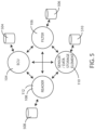
- the ECU 104 can include a data store 504.
- the filtration system 106 can include a data store 506.
- the filtration system 106 can include a filter element, which itself can include a data storage element.
- the reader 108, 112 can include a data store 508.
- the external sensor 110 can include a data store 510.
- the data stores and data storage elements can include various types of memory components including dynamic RAM (D-RAM), read only memory (ROM), static RAM (S-RAM), disk storage, flash memory, EEPROM, battery-backed RAM such as S--RAM or D-RAM and any other type of digital data storage component.
- the electronic circuit or electronic component includes volatile memory.
- the electronic circuit or electronic component includes non-volatile memory.
- the electronic circuit or electronic component can include transistors interconnected so as to provide positive feedback operating as latches or flip flops, providing for circuits that have two or more metastable states, and remain in one of these states until changed by an external input. Data storage can be based on such flip-flop containing circuits. Data storage can also be based on the storage of charge in a capacitor or on other principles.
- Data exchange between data communication tiers and components thereof can take place at various times with respect to the operational stages/states of vehicles into which filtrations systems can be installed.
- data exchange of certain types of data and between certain data communication tiers and/or components within data communication tiers can be initiated by the start or stop of a particular operational stage.
- data processing operations can be triggered by the start or stop of a particular operational stage.
- the start or stop of operational stages or substages can be stored along with a date/time stamp.
- the start or stop of operational stages can be initiate an "alert" or other communication to be generated between data communication tiers and/or between components within a tier, or to outside components, reflecting the operational stage or substage or aspects thereof.
- an input can be received by one or more data tiers that indicates whether a stage or substage has started and/or stopped or what stage the vehicle or engine is currently in.
- data can be sent from an ECU or other vehicle control system that identifies the present stage or substage and/or the start or stop of a stage or substage.
- the system herein or components thereof can use data inputs such as data inputs from sensors to determine or sense the present stage or substage and/or the start or stop of a stage or substage. Various examples of this are described in greater detail below.
- FIG. 6A is a schematic view of some engine/vehicle operational stages in accordance with various embodiments herein.
- a first operational stage is a "power on” stage 602. In some embodiments, the beginning of the "power on” stage 602 can be marked and/or logged by detecting a power input from an engine/vehicle or vehicle.
- a second operational stage is an "engine operation” stage 604. In the “engine operation” stage 604, the engine is started, running and consuming fuel, air, and emitting exhaust. In the “engine operation” stage 604, the engine speed can vary and therefore the amount of fuel and air consumed and exhaust emitted can vary.
- a third operational stage is a "power off” stage 606. In the "power off” stage 606 operation of the engine ceases.
- the start or end of a particular stage can trigger the transfer of data between or within data communication tiers as described herein.
- certain types of data are transferred from the first tier 302 onto the second tier 304 and/or third tier 306 after the start of the "power on" stage 602.
- data such as model identification data, product serial number, product specifications/capacities data, manufacturer identification data, terminal pressure drop associated with a model identification data, and threshold or maximum values for pressure drop data can be transferred from the first tier 302 onto the second tier 304 and/or third tier 306 after the start of the "power on" stage 602.
- certain types of data can be transferred from the second tier 304 and/or the third tier 306 to the first tier 302 after the start of the "power off stage 606.
- data such as run-time data, engine hours data, fuel consumption data, engine output data can be transferred from the second tier 304 and/or the third tier 306 to the first tier 302 after the start of the "power off" stage 606.
- a product serial number that uniquely identifies a particular filter element is transferred from the first tier 302 onto the second tier 304 and/or third tier 306 (or between components in the first tier 302) after the start of the "power on" stage 602.
- This information can be stored by one or more components and then each time another product serial number is received it can be checked against records to determine if this represents a new product serial number (and therefore a new replaceable filter element in this example). If it does represent a new product serial number, then a time/date stamp can be stored as a "first seen" or "first installed” date.
- a record of all unique product serial numbers representing components that are part of or installed in the system can be maintained in the data stores of one or more system components and at one or more tiers of the system.
- stored information regarding previous filter elements that have been "seen by" or “installed in” the filtration system or vehicle can be transferred to the filter element and stored therein such that each filter element that has been installed at least once includes a record of all previous filter elements that were installed in the same filtration system and/or same vehicle.
- a filtration system history can be carried by each filter element after it has been installed at least once.
- filter elements may periodically get removed for cleaning and then reinstalled, but not necessarily in the same vehicle or piece of equipment.
- a given filter element may end up storing a filtration system history for more than one vehicle or piece of equipment if it has been installed on more than one vehicle or piece of equipment.
- a given filter element can store a record of all the vehicles or pieces of equipment (by ID number or other identifier and/or type information, etc.) it has been installed on during its working life.
- the engine/vehicle operational stages of FIG. 6A can further include various substages in some embodiments.
- FIG. 6B a schematic view is shown of some substages of an engine operation stage 604 in accordance with various embodiments herein.
- the engine operation stage 604 can include an initial operation substage 614.
- airflow can be limited due to low engine RPM and/or load.
- the engine RPM may initially be relatively high and include relatively high airflow as a part of a startup/warmup sequence before falling to an idle RPM.
- the engine may also be warming up during the initial operation substage 614.
- the beginning of the initial operation substage 614 can be marked and/or logged by detecting an increase in airflow from 0 cfm to greater than 0 cfm. In some embodiments, the beginning of the initial operation substage 614 can be marked and/or logged by detecting an increase in pressure drop across a filter element from 0 (such as when there is no air flowing) to greater than 0 psi. In some embodiments, the beginning of the initial operation substage 614 can be marked and/or logged by detecting a signal from an ECU or other engine/vehicle control system. In some embodiments, the beginning of the initial operation substage 614 can be marked and/or logged by detecting a pattern related to airflow, vibration, electrical signals, and/or engine RPM consistent with a known start-up sequence.
- the start or end of the initial operation substage 614 can initiate the transfer of data between or within data communication tiers as described herein.
- the engine operation stage 604 can also include a normal load operation substage 616.
- airflow can change based on the instantaneous load on the engine and/or operating speed.
- the beginning of the normal load operation substage 616 can be marked and/or logged by detecting an increase in airflow above a threshold value for a threshold period of time, which can be reflective of an amount characteristic of engine use under load. In some embodiments, the beginning of the normal load operation substage 616 can be marked and/or logged by detecting an increase in pressure drop across a filter element above a threshold value, which can be reflective of an amount characteristic of engine use under load.
- the beginning of a normal load operation substage 616 can be marked and/or logged by detecting non-zero airflow or pressure drop in combination with another piece of information such as detecting movement with a movement sensor such as an accelerometer or a locating circuit such as a GPS circuit or similar circuit providing a geolocation value.
- a movement sensor such as an accelerometer
- a locating circuit such as a GPS circuit or similar circuit providing a geolocation value.
- the engine operation stage 604 can also include a high delta P (pressure drop) operation substage 618.
- the high delta P operation substage 618 can be marked and/or logged when a pressure drop exceeds a threshold value indicating a filter element with heavy loading in combination with machine operation at high flow.
- the threshold value can be dependent on the model ID of the particular filter element in question.
- a date/time stamp can be stored on any of the system components described herein indicating when a high delta P operation substage is entered and/or exited along with, in some embodiments, duration values and/or the serial number of a filter element being used at the start of or during the high delta P operation substage.
- the engine operation stage 604 can also include an idle operation substage 620.
- the engine may be fully warmed up but not under load and therefore the airflow, on average, can be less than during the normal load operation substage 616.
- the beginning of an idle operation substage 620 can be marked and/or logged by detecting a decrease in average airflow below a threshold value but still greater than zero.
- the engine may alternate between normal load operation and idle operation many times.
- the beginning of the idle operation substage 620 can be marked and/or logged by detecting a decrease in average pressure drop across a filter element below a threshold value but still greater than zero.
- the beginning of an idle operation substage 620 can be marked and/or logged by detecting reduced airflow or pressure drop in combination with another piece of information such as detecting a cessation in movement with a movement sensor such as an accelerometer or a locating circuit such as a GPS circuit or similar circuit providing a geolocation value.
- a movement sensor such as an accelerometer
- a locating circuit such as a GPS circuit or similar circuit providing a geolocation value.
- Entering an idle operation substage 620 can be used to initiate the transfer of data between or within data communication tiers. In many cases, idling of a motor or vehicle will precede a power off stage 606. As such, in some embodiments, entering an idle operation substage 620 can be used to initiate the transfer of data between or within data communication tiers as described below with respect to a power off stage 606 (or substages thereof).
- the power off stage 606 can include an initial operation cessation substage 626.
- airflow may suddenly cease and/or power from the vehicle may suddenly cease.
- there can still be an opportunity to transfer data between or within data communication tiers either before power ceases or using power stored in a battery or a capacitor.
- the start of an initial operation cessation substage 626 can be marked and/or logged by the detection of airflow cessation.
- the start of an initial operation cessation substage 626 can initiate the transfer of data between or within data communication tiers as described herein.
- information that uniquely identifies the filtration system and/or the vehicle into which the filter element is installed can be transferred.
- this information can be transferred to and stored by the filter element along with a time/date stamp.
- an event flag corresponding to the occurrence of the power off stage 606 or one or more power off substages can be transferred.
- one or more other pieces of data (such as one or more of those described herein) can also be transferred to and stored by the filter element.
- the power off stage 606 can also include a cover off substage 628.
- the cover off substage 628 can be marked and/or logged by the detection of a filtration system cover being removed.
- the filtration system can include a cover switch that can be actuated to provide a signal indicating that the cover has been removed.
- detection of cover removal can initiate the transfer of data between or within data communication tiers as described herein.
- detection of cover removal can initiate the transfer of data to the filter element from other components in the same or different tiers in anticipation that the filter element will shortly be removed.
- the power off stage 606 can also include a filter element removal substage 630.
- the filter element removal substage 630 can be marked and/or logged by detecting of a filter element being removed from a filter system housing.
- a filter element removal substage 630 can be marked and/or logged by a sudden and sustained (for greater than a threshold amount of time) loss of communication (wired or wireless) with a filter element.
- an event flag corresponding to the occurrence of the filter element removal substage 630 can be stored by one or more components at one or more of the tiers described herein.
- the conditions observed immediately after a filter element is replaced can be measured and stored and then used to determine other information about the operating status of a filtration system or components thereof.
- a filtration system including a primary filter element and a secondary (or safety) filter element
- the primary filter element is replaced/serviced at a much shorter interval than the secondary or safety filter element.
- the secondary or safety element has already been in use and may already have some degree of loading.
- Measuring the initial operating conditions can provide an ability to assess the state of the secondary or safety element.
- the higher the pressure drop (restriction) observed initially after a new primary filter element is installed the greater the loading on the secondary or safety element and therefore the less life it has left.
- measuring the pressure drop after a new primary filter element is installed can allow the system to provide an end of life estimation that is specific for the secondary or safety filter element.
- a loading curve (relating a degree of restriction versus a value reflective of the magnitude of use of the filter element such as hours of use) or loading coefficients specific for the model ID of the filter element can be used to estimate when a filter element will reach a threshold value of loading based on the current degree of restriction and how many hours of use it took to reach that degree of restriction.
- a level of restriction provided solely by the secondary or safety filter can be derived and then an estimation of end of life for the secondary or safety filter can be derived using a loading curve or loading coefficients specific for the secondary or safety filter.
- a total pressure drop through the filter elements reflects contributions from both the primary and the secondary or safety elements
- knowing the starting condition of the secondary or safety element provides an ability to more accurately track loading of the primary filter element and therefor provide a more accurate end of life estimation for the primary filter element.
- the contribution to total restriction provided by the secondary or safety filter can be estimated and then be subtracted to arrive at a more accurate measurement of restrictions for the primary filter element.
- other estimations regarding the primary and/or secondary or safety filter element that can be performed herein can include, but are not limited to, estimations of time or usage (miles) until a threshold restriction (pressure drop) value is reached or calculations on economically optimal replacement intervals.
- the system can measure the pressure drop after a new primary filter element is installed and store this value. Then this value can be used in a calculation to estimate the condition and/or calculate an end of life value for the secondary or safety filter element. This value can also be used during calculations performed during ongoing operation to calculate the condition and/or calculate an end of life value for the primary filter element while correcting for the contribution to restriction provided by the secondary or safety filter element.
- data can be transferred to and then processed at the second tier 304, such as at the reader device 108, 112.
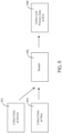
- Data can be collected 702 by an external sensor.
- Data can also be collected 704 by a filtration system.
- Data can also be collected 706 by the ECU.
- Data, as collected by the external sensor, the filtration system, and the ECU can be transferred to the reader (on-vehicle or off-vehicle such as a hub) and can then be processed 708 by the reader. Exemplary data processing operations are described in greater detail below and can result in processed data.
- the resulting processed data can then be transferred to the ECU.
- data from the sensor(s) and/or filter(s) can be transferred directly to and then processed at the third tier 306, such as at the ECU 104.
- FIG. 8 a schematic view of data transfer between data communication tiers associated with a filtration system is shown in accordance with various embodiments herein.
- Data can be collected 802 by an external sensor.
- Data can also be collected 804 by a filtration system.
- Data, as collected by the external sensor and the filtration system can then be transferred to the ECU and can then be processed 806 by the ECU.
- data can be collected by the first tier 302 and then transferred to the second tier, such as the reader (on-vehicle or off-vehicle such as a hub), and then transferred to and processed at the third tier 306, such as at the ECU 104.
- the second tier such as the reader (on-vehicle or off-vehicle such as a hub)
- the third tier 306, such as at the ECU 104 Referring now to FIG. 9 , a schematic view of data transfer between data communication tiers associated with a filtration system is shown in accordance with various embodiments herein.
- Data can be collected 902 by an external sensor.
- Data can also be collected 904 by a filtration system.
- the data collected by the first tier can then be transferred 906 to the second tier, such as to a reader (on-vehicle or off-vehicle such as a hub).
- the data can then be transferred to the ECU and can then be processed 908 by the ECU.
- data can be collected by the first tier 302 and then transferred to the second tier, such as the reader (on-vehicle or off-vehicle such as a hub), and processed at the second tier 304.
- the processed data can then be transferred to the third tier 306, such as at the ECU 104.
- FIG. 10 a schematic view of data transfer between data communication tiers associated with a filtration system is shown in accordance with various embodiments herein.
- Data can be collected 1002 by an external sensor.
- Data can also be collected 1004 by a filtration system.
- the data collected by the first tier can then be transferred to and processed 1006 by the second tier, such as the reader (on-vehicle or off-vehicle such as a hub).
- the processed data can then be transferred 1008 to the ECU.
- data can be transferred to and then processed at the second tier 304, such as at the reader device 108, 112 and then passed back to the first tier 302 and on to the third tier 306.
- FIG. 11 a schematic view of data transfer between data communication tiers associated with a filtration system is shown in accordance with various embodiments herein.
- Data can be collected 1102 by an external sensor.
- Data can also be collected 1104 by a filtration system.
- Data can also be collected 1106 by the ECU.
- Data, as collected by the external sensor, the filtration system, and the ECU can be transferred to the reader (on-vehicle or off-vehicle such as a hub) and can then be processed 1108 by the reader.
- the resulting processed data can then be transferred 1110 to the first tier 302, such as the filtration system.
- the resulting processed data can also be transferred 1112 from the reader (on-vehicle or off-vehicle such as a hub) and be received 1114 by the ECU and, in some cases, the processed data can specifically be transferred from the first tier 302 to the second tier 304 and then to the ECU.
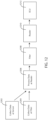
- Data can be collected 1202 by an external sensor.
- Data can also be collected 1204 by a filtration system.
- Data, as collected by the external sensor, the filtration system, and the ECU can be transferred to the reader (on-vehicle or off-vehicle such as a hub) and can then be processed 1206 by the reader.
- the resulting processed data can then be transferred 1208 to the first tier 302, such as the filtration system.
- the resulting processed data can also be transferred 1210 from the reader (on-vehicle or off-vehicle such as a hub) and be received 1212 by the ECU and, in some cases, the processed data can specifically be transferred from the first tier 302 to the second tier 304 and then to the ECU.
- Data can be collected 1302 by an ECU.
- Data, as collected by the ECU can be transferred to the reader (on-vehicle or off-vehicle such as a hub) and can then be processed 1304 by the reader.
- the resulting processed data can then be transferred 1306 to the first tier 302, such as the filtration system.
- the resulting processed data can also be transferred 1308 from the reader and be received 1310 by the ECU.
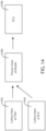
- Data can be collected 1402 by a filtration system.
- Data can also be collected 1404 by an ECU.
- the data collected by the first tier can then be transferred to and processed 1406 by the second tier, such as the reader (on-vehicle or off-vehicle such as a hub).
- the processed data can then be transferred 1408 to the ECU.
- Data herein can include sensor data including, but not limited to, data from temperature sensors, pressure sensors, differential pressure sensors, flow sensors, particulate sensors, contaminant sensors, electrical property sensors, geolocation sensors, sound sensors, vibration sensors, and the like.
- Data herein can also include data regarding one or more components of the system including, but not limited to, product model identification, product serial number, product specifications/capacities, manufacturer identification, manufacturing plant identification, manufacturing date, terminal pressure drop associated with a model identification, threshold or maximum values for pressure drop, filter element loading curves, filter element loading coefficients, system component manufacturing data, software updates, firmware updates, algorithm information (such as end-of-life prediction, regeneration prediction/initiation, performance calculation/tracking), data representing the output of algorithms, data regarding versions of software/firmware/algorithm updates including dates and versions, fuel cost data, fuel formulation data, emissions regulation data, cost of filter elements, labor cost to change filter element, data revision date, typical fuel consumption rates for particular machines, fuel usage penalty factors for operating with increase pressure drop for a machine associated with a particular filtration system or filtration system component model ID, run-time data, engine hours data, fuel consumption data, engine output data, and the like.
- data herein can include messages or warnings regarding system status or performance such as maximum or threshold pressure drop exceeded, end-of-life (EOL) reached or within a threshold amount of being reached, maximum or threshold particulate passage exceeded, safe operating reserve capacity maximum or threshold exceeded, improper components (such as filter elements) detected, non-genuine components (such as filter elements) detected, and the like.
- EOL end-of-life
- Data processing operations herein can include various operations including, but not limited to, averaging, time-averaging, statistical analysis, normalizing, aggregating, sorting, deleting, traversing, transforming, condensing (such as eliminating selected data and/or converting the data to a less granular form), compressing (such as using a compression algorithm), merging, inserting, timestamping, filtering, discarding outliers, calculating trends and trendlines (linear, logarithmic, polynomial, power, exponential, moving average, etc.), predicting EOL, identifying an EOL condition, predicting performance, predicting costs associated with replacing filter elements vs. not-replacing filter elements, and the like.
- Normalizing can include, but is not limited to, adjusting one or more values based on another value or set of values. As just one example, pressure drop data reflective of pressure drop across a filter element can normalized by accounting for air flow.
- Circuitry associated with systems herein can include various specific electronic components in order to execute operations as described herein.
- FIG. 15 a schematic view is shown of some components of a system in accordance with various embodiments herein.
- the first system element 1544 can be part of a filtration system, filter element, filter housing, sensor or another type of system component.
- the second system element 1546 can be part of a reader device (on-vehicle or off-vehicle), filtration system, filter housing, or another type of system component.
- Components associated with a first system element 1544 can include one or more of an antenna 1510, a power supply circuit 1512 (which can include one or more of a battery, a capacitor, a power-receiver such as a wireless power receiver), a processing circuit 1502 (which can include a processor, a microcontroller, an ASIC, or the like), a memory storage circuit 1504 (which can include volatile or non-volatile electronic memory), a communication circuit 1506, and a cryptographic circuit 1508 (which can include a specialized cryptographic processor and/or data associated with cryptographic functions).
- a wireless power receiver can include an LC circuit.
- the wireless power receiver can include an RF power receiver.
- one or more components of a power supply circuit, such as a wireless power receiver can be disposed on or in the filter body.
- first system element 1544 may not include all of the components shown and described with respect to FIG. 15 .
- first system element 1544 may include additional components beyond what is shown and described with respect to FIG. 15 .
- Components associated with a second system element 1546 can include one or more of an antenna 1522, a power supply circuit 1524 (which can include one or more of a battery, a capacitor, or a power-receiver), a processing circuit 1526 (which can include a processor, a microcontroller, an ASIC, or the like), a memory storage circuit 1528 (which can include volatile or non-volatile memory), a communication circuit 1530, a cryptographic circuit 1532 (which can include a specialized cryptographic processor and/or data associated with cryptographic functions), a clock circuit 1534, and a location circuit 1536.
- a power supply circuit 1524 which can include one or more of a battery, a capacitor, or a power-receiver
- a processing circuit 1526 which can include a processor, a microcontroller, an ASIC, or the like
- a memory storage circuit 1528 which can include volatile or non-volatile memory
- a communication circuit 1530 which can include a cryptographic circuit 1532 (
- communication between components of a system can be conducted wirelessly. However, in other embodiments, communication between components of a system can be conducted through a wired connection.
- FIG. 16 a schematic view is shown of components of a system in accordance with various embodiments herein.
- Components associated with a first system element 1544 can include one or more of a processing circuit 1502 (which can include a processor, a microcontroller, an ASIC, or the like), a memory storage circuit 1504 (which can include volatile or non-volatile electronic memory), a communication circuit 1506, and a cryptographic circuit 1508 (which can include a specialized cryptographic processor and/or data associated with cryptographic functions).
- Power can be provided from a power supply 1606 that is external to the first system element (and could be from a vehicle or another source).
- the first system element 1544 can be connected to the power supply via electrical contacts 1602. As represented in FIG. 16 , the power supply 1606 is a DC power source, but AC power sources are also contemplated herein.
- first system element 1544 may not include all of the components shown and described with respect to FIG. 16 .
- first system element 1544 may include additional components beyond what is shown and described with respect to FIG. 16 .
- Components associated with a second system element 1546 can include one or more of a processing circuit 1526 (which can include a processor, a microcontroller, an ASIC, or the like), a memory storage circuit 1528 (which can include volatile or non-volatile memory), a communication circuit 1530, a cryptographic circuit 1532 (which can include a specialized cryptographic processor and/or data associated with cryptographic functions), a clock circuit 1534, and a location circuit 1536.
- Power can be provided from a power supply 1606 that is external to the data storage element (and could be from a vehicle or another source).
- the second system element 1546 can be connected to the first system element 1544 (such as when the filter element is installed in a filter housing) via wires 1604.
- the phrase “configured” describes a system, apparatus, or other structure that is constructed or configured to perform a particular task or adopt a particular configuration to.
- the phrase “configured” can be used interchangeably with other similar phrases such as arranged and configured, constructed and arranged, constructed, manufactured and arranged, and the like.
Landscapes
- Engineering & Computer Science (AREA)
- Chemical & Material Sciences (AREA)
- Physics & Mathematics (AREA)
- General Physics & Mathematics (AREA)
- Theoretical Computer Science (AREA)
- Databases & Information Systems (AREA)
- Chemical Kinetics & Catalysis (AREA)
- General Engineering & Computer Science (AREA)
- Computational Linguistics (AREA)
- Data Mining & Analysis (AREA)
- Mechanical Engineering (AREA)
- Combustion & Propulsion (AREA)
- Arrangements For Transmission Of Measured Signals (AREA)
- Testing Of Engines (AREA)
- Computer Networks & Wireless Communication (AREA)
- Combined Controls Of Internal Combustion Engines (AREA)
Abstract
Description
- This application is being filed as a
PCT International Patent application on September 18, 2019 in the name of Donaldson Company, Inc., a U.S. national corporation, applicant for the designation of all countries and Daniel E. Adamek, a U.S. Citizen, Brian R. Tucker, a U.S. Citizen, David W. Mulder a U.S. Citizen, Matthew Anderson, a U.S. Citizen and Michael J. Lockert, a U.S. Citizen, inventors for the designation of all countries, and claims priority to U.S. Provisional Patent Application No. 62/732,844, filed September 18, 2018 - Embodiments herein relate to filtration systems with multitiered data exchange capabilities.
- Fluid streams often carry particulate material therein. In many instances, it is desirable to remove some or all of the particulate material from a fluid flow stream. For example, air intake streams to engines for motorized vehicles or power generation equipment, gas streams directed to gas turbines, and air streams to various combustion furnaces, often include particulate material therein. The particulate material, should it reach the internal workings of the various mechanisms involved, can cause substantial damage thereto. It is therefore desirable for such systems to remove the particulate material from the fluid flow upstream of the engine, turbine, furnace or other equipment involved. A variety of air filter or gas filter arrangements have been developed for particulate removal. Beyond particulate removal, filtration systems can also be used as gas phase or liquid phase contaminant removal systems.
- Embodiments include filter elements and filtration systems. In an embodiment, a filtration system with multitiered data exchange capabilities is included. The filtration system can include a first data communication tier. The first data communication tier can include a filter element, the filter element storing data, and a first sensor. The filtration system can include a second data communication tier. The second data communication tier can include a reader device in communication with at least one of the filter element and the first sensor. The filtration system can include a third data communication tier. The third data communication tier can include an engine control unit (ECU) in communication with the reader device. The ECU can store data. The second data communication tier can receive data from the first data communication tier and the third data communication tier. The second data communication tier can execute operations on the received data to create a processed data set. The second data communication tier can send the processed data set to the third data communication tier.
- In an embodiment, a filtration system with multitiered data exchange capabilities is included. The filtration system can include a first data communication tier. The first data communication tier can include a filter element. The filter element can include a first sensor configured to generate data. The filtration system can include a second data communication tier. The second data communication tier can include a reader device in communication with the first sensor. The second data communication tier can receive data from the first data communication tier and a third data communication tier. The second data communication tier can execute operations on the received data to create a processed data set. The second data communication tier can send the processed data set to the third data communication tier.
- In an embodiment, a filtration system with multitiered data exchange capabilities is included. The filtration system can include a first data communication tier. The first data communication tier can include a first sensor configured to generate data and a filter element. The filter element can include a second sensor configured to generate data. The filtration system can include a second data communication tier. The second data communication tier can include an engine control unit (ECU). The ECU can store data. The second data communication tier can receive data from the first data communication tier. The second data communication tier can execute operations on the received data to create a processed data set.
- In an embodiment, a filtration system with multitiered data exchange capabilities is included. The filtration system can include a first data communication tier. The first data communication tier can include a first sensor configured to generate data and a filter element. The filter element can include a second sensor configured to generate data. The filtration system can include a second data communication tier. The second data communication tier can include a reader device in communication with the first sensor and the second sensor. The filtration system can also include a third data communication tier including an engine control unit (ECU) in communication with the reader device. The second data communication tier can receive data from the first data communication tier. The third data communication tier can receive data from the second data communication tier. The third data communication tier can execute operations on the received data to create a processed data set.
- In an embodiment, a filtration system with multitiered data exchange capabilities is included. The filtration system can include a first data communication tier. The first data communication tier can include a filter element. The filter element can include a first sensor configured to generate data. The filtration system can include a second data communication tier. The second data communication tier can include a reader device in communication with the first sensor. The filtration system can include a third data communication tier. The third data communication tier can include an engine control unit (ECU) in communication with the reader device. The second data communication tier can receive data from the first data communication tier. The second data communication tier can execute operations on the received data to create a processed data set. The second data communication tier can send the processed data set to the third data communication tier.
- In an embodiment, a filtration system with multitiered data exchange capabilities is included. The filtration system can include a first data communication tier. The first communication tier can include a filter element, the filter element including a first sensor configured to generate data. The filtration system can include a second data communication tier. The second data communication tier can include a reader device in communication with the first sensor. The filtration system can include a third data communication tier comprising an engine control unit (ECU) in communication with the reader device. The second data communication tier can receive data from the first data communication tier and the third data communication tier. The second data communication tier can execute operations on the received data to create a processed data set. The second data communication tier can send the processed data set to the filter element. The second data communication tier can send the processed data set to the third data communication tier.
- In an embodiment, a filtration system with multitiered data exchange capabilities is included. The first data communication tier can include a first sensor configured to generate data and a filter element. The filter element can include a second sensor configured to generate data. The filtration system can include a second data communication tier. The second data communication tier can include a reader device in communication with the first sensor and the second sensor. The filtration system can further include a third data communication tier including an engine control unit (ECU) in communication with the reader device. The second data communication tier can receive data from the first data communication tier. The second data communication tier can execute operations on the received data to create a processed data set. The second data communication tier can send the processed data set to the filter element. The second data communication tier can send the processed data set to the third data communication tier.
- In an embodiment, a filtration system with multitiered data exchange capabilities is included. The filtration system can include a first data communication tier including a filter element. The filtration system can include a second data communication tier including a reader device in communication with the filter element. The filtration system can include a third data communication tier including an engine control unit (ECU) in communication with the reader device. The second data communication tier can receive data from the third data communication tier. The second data communication tier can execute operations on the received data to create a processed data set. The second data communication tier can send the processed data set to the filter element. The second data communication tier can send the processed data set to the third data communication tier.
- In an embodiment, a filtration system with multitiered data exchange capabilities is included. The filtration system can include a first data communication tier. The first data communication tier can include a filter element including a first sensor configured to generate data. The filtration system can also include a second data communication tier including a reader device in communication with the filter element. The filtration system can include a third data communication tier including an engine control unit (ECU) in communication with the reader device. The second data communication tier can receive data from the first data communication tier. The second data communication tier can execute operations on the received data to create a processed data set. The second data communication tier can send the processed data set to the third data communication tier.
- In an embodiment, a filtration system is included. The filtration system can include a device configured to be in electronic communication with a filter element. The device can include a processing circuit and a communication circuit. The device can receive data and determine an operational stage and/or substage of an engine or vehicle. Data communication between or amongst one or more data communication tiers of the filtration system can be directed based on a determination of the operational stage and/or substage of the engine or vehicle.
- In an embodiment, a filtration system with multitiered data exchange capabilities is included. The filtration system can include a first data communication tier including a filter element. The filter element can include a data storage element. The filtration system can include a second data communication tier. The second data communication tier can include a reader device. The reader device can include a processing circuit and a communication circuit. The second data communication tier can receive data from the first data communication tier uniquely identifying the filter element. The second data communication tier can send data to the first data communication tier specifying previous filter elements installed in the filtration system.
- In an embodiment, a filtration system with multitiered data exchange capabilities is included. The filtration system can include a first data communication tier including a first sensor. The filtration system can include a second data communication tier including a reader device in communication with the first sensor. The reader device can include a processing circuit and a communication circuit. The second data communication tier can measure a system property when a primary filter element is first installed in the filtration system and can store the system property value as a baseline value.
- This summary is an overview of some of the teachings of the present application and is not intended to be an exclusive or exhaustive treatment of the present subject matter. Further details are found in the detailed description and appended claims. Other aspects will be apparent to persons skilled in the art upon reading and understanding the following detailed description and viewing the drawings that form a part thereof, each of which is not to be taken in a limiting sense. The scope herein is defined by the appended claims and their legal equivalents.
- Aspects may be more completely understood in connection with the following drawings, in which:
-
FIG. 1 is a schematic view of components of a filtration system in accordance with various embodiments herein. -
FIG. 2 is a schematic cross-sectional view of a filtration system with a primary filter element and a safety filter element installed therein in accordance with various embodiments herein. -
FIG. 3 is a schematic view of data communication tiers associated with a filtration system, and components thereof, in accordance with various embodiments herein. -
FIG. 4 is a schematic view of components of systems in accordance with various embodiments herein. -
FIG. 5 is a schematic view of components of systems in accordance with various embodiments herein. -
FIG. 6A is a schematic view of operational stages in accordance with various embodiments herein. -
FIG. 6B is a schematic view of operational substages in accordance with various embodiments herein. -
FIG. 6C is a schematic view of operational substages in accordance with various embodiments herein. -
FIG. 7 is a schematic view of data transfer between tiers associated with a filtration system in accordance with various embodiments herein. -
FIG. 8 is a schematic view of data transfer between data communication tiers associated with a filtration system in accordance with various embodiments herein. -
FIG. 9 is a schematic view of data transfer between data communication tiers associated with a filtration system in accordance with various embodiments herein. -
FIG. 10 is a schematic view of data transfer between data communication tiers associated with a filtration system in accordance with various embodiments herein. -
FIG. 11 is a schematic view of data transfer between data communication tiers associated with a filtration system in accordance with various embodiments herein. -
FIG. 12 is a schematic view of data transfer between data communication tiers associated with a filtration system in accordance with various embodiments herein. -
FIG. 13 is a schematic view of data transfer between data communication tiers associated with a filtration system in accordance with various embodiments herein. -
FIG. 14 is a schematic view of data transfer between data communication tiers associated with a filtration system in accordance with various embodiments herein. -
FIG. 15 is a schematic view of components of a system in accordance with various embodiments herein. -
FIG. 16 is a schematic view of components of a system in accordance with various embodiments herein. - While embodiments are susceptible to various modifications and alternative forms, specifics thereof have been shown by way of example and drawings, and will be described in detail. It should be understood, however, that the scope herein is not limited to the particular embodiments described. On the contrary, the intention is to cover modifications, equivalents, and alternatives falling within the spirit and scope herein.
- Various types of data regarding filtration system performance and/or system status can be gathered using sensors. The sensors can be associated with various components of a filtration system or can be remote from the filtration system. The sensors can include, but are not limited to, temperature sensors, pressure sensors, differential pressure sensors, flow sensors, particulate sensors, contaminant sensors, electrical property sensors, geolocation sensors, proximity sensors, sound sensors, vibration sensors, and the like. In some embodiments, data can be generated by another system, such as an engine control unit or module (ECU/ECM) and then can be shared with components of a filtration system. Data generated by other systems can include, but are not limited to, run-time data, engine hours data, fuel consumption data, engine output data, and the like.
- In accordance with various embodiments herein, data can be generated at a particular tier or layer of the overall system hierarchy and then passed to other system data communication tiers for processing, storage, calculations, or other operations. In various embodiments, after one or more operations are performed on or using such data, it can be passed onto other data communication tiers either in its original form, or in a processed form. In various embodiments, processed data can be passed back to a tier or layer from which sensor data or other input data was originally received. For example, processed data can be sent back to a filter element or external sensor for evaluation, processing, and/or storage.
- Referring now to
FIG. 1 , a schematic view is shown of components associated with a filtration system in accordance with various embodiments herein. Thevehicle 100 is powered by anengine 102 which can be controlled with an engine control unit (ECU) 104. Afiltration system 106 is installed on thevehicle 100 and can be in communication with theECU 104, an on-vehicle (or on-system)reader device 108, one or moreexternal sensors 110, and in some embodiments an off-vehicle reader device 112 or hub. It will be appreciated that for ease of illustrationFIG. 1 only shows a limited number of components that can be associated with systems herein and that in various embodiments a greater or lesser number of components can be included. - Referring now to
FIG. 2 , a schematic cross-sectional view of afiltration system 106 with aprimary filter element 220 and asafety filter element 221 installed therein in accordance with various embodiments herein. This serves as merely one example of a filtration system and many other types of filtration systems are contemplated herein. With reference to theprimary filter element 220, afilter body 232 and filtermedia 234 disposed within thefilter body 232 can be included. However, it will be appreciated that thesafety filter element 221, as well as other filter elements can similarly include a filter body and filter media. Thefiltration system 106 can include ahousing 202 comprising afluid inlet 210 and afluid outlet 212, the housing defining an internal volume. Aprimary filter element 220 can be disposed within the internal volume of thehousing 202. and can be configured to be removably disposed therein. The proximal end of the internal volume is configured to engage with aremovable cover 204 that fits adjacent to the proximal end in order to seal off the proximal end of the housing from the flow of fluid there through. Theremovable cover 204 can engage the proximal end and remain attached thereto through various devices or structures including threads, friction-fit mechanisms, latches, buckles, snap-fit mechanisms, or the like. - A functional unit 222 such as a sensor unit or a data storage element can be associated with the
safety filter element 221. Afunctional unit 224 such as a sensor unit or a data storage element can also be associated with theprimary filter element 220. In some embodiments, afunctional unit 226 can also be associated with the filter housing. Various types of sensors and data storage elements are contemplated herein including those referenced above and below. - Referring now to
FIG. 3 , a schematic view is shown of data communication tiers or layers associated with a filtration system in accordance with various embodiments herein. Thefirst tier 302 includes sensors and data storage elements and can specifically include sensors and data storage elements associated directly with the filtration system 106 (which can be associated with the filter element and/or the filter housing) and anyexternal sensors 110 and data storage elements. Thesecond tier 304 can include areader device first tier 302. Thethird tier 306 can include elements directly associated with non-filtration systems of the vehicle such as theECU 104. - Data can move between data communication tiers wirelessly or through direct wired connections. In many cases, data can be transferred in a digital format, however, in some embodiments analog signals can also be transferred between system components.
- While
FIG. 3 illustrates the exchange of data directly between thefirst tier 302 and thesecond tier 304 and between thesecond tier 304 and thethird tier 306, it will be appreciated that the exchange of data can also take place directly between thefirst tier 302 and thethird tier 306, as well as between components in the same tier, such as between the filtration system 106 (or components thereof) and anexternal sensor 110. Referring now toFIG. 4 , a schematic view of components of systems in accordance with various embodiments herein. Afiltration system 106 can exchange data with anECU 104, a reader (on-vehicle 108 or off-vehicle 112), and asensor 110. Similarly, theECU 104 can exchange data with afiltration system 106, areader sensor 110. Further, thereader 108 can exchange data with anECU 104, afiltration system 106, and anexternal sensor 110. Finally, theexternal sensor 110 can exchange data with anECU 104, afiltration system 106, and areader - Data can be stored with multiple components of the system. Referring now to
FIG. 5 , a schematic view of components of systems in accordance with various embodiments herein is shown. TheECU 104 can include adata store 504. Thefiltration system 106 can include adata store 506. In various embodiments, thefiltration system 106 can include a filter element, which itself can include a data storage element. Thereader data store 508. Further, theexternal sensor 110 can include adata store 510. - The data stores and data storage elements can include various types of memory components including dynamic RAM (D-RAM), read only memory (ROM), static RAM (S-RAM), disk storage, flash memory, EEPROM, battery-backed RAM such as S--RAM or D-RAM and any other type of digital data storage component. In some embodiments, the electronic circuit or electronic component includes volatile memory. In some embodiments, the electronic circuit or electronic component includes non-volatile memory. In some embodiments, the electronic circuit or electronic component can include transistors interconnected so as to provide positive feedback operating as latches or flip flops, providing for circuits that have two or more metastable states, and remain in one of these states until changed by an external input. Data storage can be based on such flip-flop containing circuits. Data storage can also be based on the storage of charge in a capacitor or on other principles.
- Data exchange between data communication tiers and components thereof can take place at various times with respect to the operational stages/states of vehicles into which filtrations systems can be installed. In some embodiments, data exchange of certain types of data and between certain data communication tiers and/or components within data communication tiers, can be initiated by the start or stop of a particular operational stage. In some embodiments, data processing operations can be triggered by the start or stop of a particular operational stage. In some embodiments, the start or stop of operational stages or substages can be stored along with a date/time stamp. In some embodiments, the start or stop of operational stages can be initiate an "alert" or other communication to be generated between data communication tiers and/or between components within a tier, or to outside components, reflecting the operational stage or substage or aspects thereof. In some embodiments, an input can be received by one or more data tiers that indicates whether a stage or substage has started and/or stopped or what stage the vehicle or engine is currently in. By way of example, data can be sent from an ECU or other vehicle control system that identifies the present stage or substage and/or the start or stop of a stage or substage. In some embodiments, the system herein or components thereof can use data inputs such as data inputs from sensors to determine or sense the present stage or substage and/or the start or stop of a stage or substage. Various examples of this are described in greater detail below.
-
FIG. 6A is a schematic view of some engine/vehicle operational stages in accordance with various embodiments herein. A first operational stage is a "power on"stage 602. In some embodiments, the beginning of the "power on"stage 602 can be marked and/or logged by detecting a power input from an engine/vehicle or vehicle. A second operational stage is an "engine operation"stage 604. In the "engine operation"stage 604, the engine is started, running and consuming fuel, air, and emitting exhaust. In the "engine operation"stage 604, the engine speed can vary and therefore the amount of fuel and air consumed and exhaust emitted can vary. A third operational stage is a "power off"stage 606. In the "power off"stage 606 operation of the engine ceases. - In various embodiments, the start or end of a particular stage (or one or more substages described below) can trigger the transfer of data between or within data communication tiers as described herein. By way of example, in some embodiments, certain types of data are transferred from the
first tier 302 onto thesecond tier 304 and/orthird tier 306 after the start of the "power on"stage 602. For example, data such as model identification data, product serial number, product specifications/capacities data, manufacturer identification data, terminal pressure drop associated with a model identification data, and threshold or maximum values for pressure drop data can be transferred from thefirst tier 302 onto thesecond tier 304 and/orthird tier 306 after the start of the "power on"stage 602. Similarly, certain types of data can be transferred from thesecond tier 304 and/or thethird tier 306 to thefirst tier 302 after the start of the "power offstage 606. For example, data such as run-time data, engine hours data, fuel consumption data, engine output data can be transferred from thesecond tier 304 and/or thethird tier 306 to thefirst tier 302 after the start of the "power off"stage 606. - In some embodiments, a product serial number that uniquely identifies a particular filter element (in some cases along with other information) is transferred from the
first tier 302 onto thesecond tier 304 and/or third tier 306 (or between components in the first tier 302) after the start of the "power on"stage 602. This information can be stored by one or more components and then each time another product serial number is received it can be checked against records to determine if this represents a new product serial number (and therefore a new replaceable filter element in this example). If it does represent a new product serial number, then a time/date stamp can be stored as a "first seen" or "first installed" date. A record of all unique product serial numbers representing components that are part of or installed in the system can be maintained in the data stores of one or more system components and at one or more tiers of the system. - In some embodiments, stored information regarding previous filter elements (including, but not limited to, product serial number, model ID, manufacturer ID, manufacturing plant ID, replacement intervals, performance history, or any of the other types of data referenced herein) that have been "seen by" or "installed in" the filtration system or vehicle can be transferred to the filter element and stored therein such that each filter element that has been installed at least once includes a record of all previous filter elements that were installed in the same filtration system and/or same vehicle. In this manner, a filtration system history can be carried by each filter element after it has been installed at least once. In a vehicle/equipment fleet scenario, filter elements may periodically get removed for cleaning and then reinstalled, but not necessarily in the same vehicle or piece of equipment. As such, a given filter element may end up storing a filtration system history for more than one vehicle or piece of equipment if it has been installed on more than one vehicle or piece of equipment. Similarly, a given filter element can store a record of all the vehicles or pieces of equipment (by ID number or other identifier and/or type information, etc.) it has been installed on during its working life.
- The engine/vehicle operational stages of
FIG. 6A can further include various substages in some embodiments. Referring now toFIG. 6B , a schematic view is shown of some substages of anengine operation stage 604 in accordance with various embodiments herein. At tire beginning of theengine operation stage 604, the engine is started and, in the case of an air filter, air starts to move through the filtration system. Theengine operation stage 604 can include aninitial operation substage 614. During theinitial operation substage 614, airflow can be limited due to low engine RPM and/or load. However, in some embodiments, the engine RPM may initially be relatively high and include relatively high airflow as a part of a startup/warmup sequence before falling to an idle RPM. The engine may also be warming up during theinitial operation substage 614. - In some embodiments, the beginning of the
initial operation substage 614 can be marked and/or logged by detecting an increase in airflow from 0 cfm to greater than 0 cfm. In some embodiments, the beginning of theinitial operation substage 614 can be marked and/or logged by detecting an increase in pressure drop across a filter element from 0 (such as when there is no air flowing) to greater than 0 psi. In some embodiments, the beginning of theinitial operation substage 614 can be marked and/or logged by detecting a signal from an ECU or other engine/vehicle control system. In some embodiments, the beginning of theinitial operation substage 614 can be marked and/or logged by detecting a pattern related to airflow, vibration, electrical signals, and/or engine RPM consistent with a known start-up sequence. - In various embodiments, the start or end of the
initial operation substage 614 can initiate the transfer of data between or within data communication tiers as described herein. - The
engine operation stage 604 can also include a normalload operation substage 616. During the normalload operation substage 616, airflow can change based on the instantaneous load on the engine and/or operating speed. - In some embodiments, the beginning of the normal
load operation substage 616 can be marked and/or logged by detecting an increase in airflow above a threshold value for a threshold period of time, which can be reflective of an amount characteristic of engine use under load. In some embodiments, the beginning of the normalload operation substage 616 can be marked and/or logged by detecting an increase in pressure drop across a filter element above a threshold value, which can be reflective of an amount characteristic of engine use under load. In some embodiments, the beginning of a normalload operation substage 616 can be marked and/or logged by detecting non-zero airflow or pressure drop in combination with another piece of information such as detecting movement with a movement sensor such as an accelerometer or a locating circuit such as a GPS circuit or similar circuit providing a geolocation value. - The
engine operation stage 604 can also include a high delta P (pressure drop)operation substage 618. The high deltaP operation substage 618, can be marked and/or logged when a pressure drop exceeds a threshold value indicating a filter element with heavy loading in combination with machine operation at high flow. The threshold value can be dependent on the model ID of the particular filter element in question. In various embodiments, a date/time stamp can be stored on any of the system components described herein indicating when a high delta P operation substage is entered and/or exited along with, in some embodiments, duration values and/or the serial number of a filter element being used at the start of or during the high delta P operation substage. - The
engine operation stage 604 can also include anidle operation substage 620. During theidle operation substage 620, the engine may be fully warmed up but not under load and therefore the airflow, on average, can be less than during the normalload operation substage 616. As such, the beginning of anidle operation substage 620 can be marked and/or logged by detecting a decrease in average airflow below a threshold value but still greater than zero. In practice, the engine may alternate between normal load operation and idle operation many times. In some embodiments, the beginning of theidle operation substage 620 can be marked and/or logged by detecting a decrease in average pressure drop across a filter element below a threshold value but still greater than zero. In some embodiments, the beginning of anidle operation substage 620 can be marked and/or logged by detecting reduced airflow or pressure drop in combination with another piece of information such as detecting a cessation in movement with a movement sensor such as an accelerometer or a locating circuit such as a GPS circuit or similar circuit providing a geolocation value. - Entering an
idle operation substage 620 can be used to initiate the transfer of data between or within data communication tiers. In many cases, idling of a motor or vehicle will precede a power offstage 606. As such, in some embodiments, entering anidle operation substage 620 can be used to initiate the transfer of data between or within data communication tiers as described below with respect to a power off stage 606 (or substages thereof). - Referring now to
FIG. 6C , a schematic view is shown of some substages of a power offstage 606. The power offstage 606 can include an initialoperation cessation substage 626. During the initialoperation cessation substage 626, airflow may suddenly cease and/or power from the vehicle may suddenly cease. In various circumstances, there can still be an opportunity to transfer data between or within data communication tiers either before power ceases or using power stored in a battery or a capacitor. - In some embodiments, the start of an initial
operation cessation substage 626 can be marked and/or logged by the detection of airflow cessation. The start of an initialoperation cessation substage 626 can initiate the transfer of data between or within data communication tiers as described herein. In some embodiments, information that uniquely identifies the filtration system and/or the vehicle into which the filter element is installed can be transferred. In some embodiments, this information can be transferred to and stored by the filter element along with a time/date stamp. In some embodiments, an event flag corresponding to the occurrence of the power offstage 606 or one or more power off substages can be transferred. In some embodiments, one or more other pieces of data (such as one or more of those described herein) can also be transferred to and stored by the filter element. - The power off
stage 606 can also include a cover offsubstage 628. The cover offsubstage 628 can be marked and/or logged by the detection of a filtration system cover being removed. In some embodiments, the filtration system can include a cover switch that can be actuated to provide a signal indicating that the cover has been removed. In some embodiments, detection of cover removal can initiate the transfer of data between or within data communication tiers as described herein. In some embodiments, detection of cover removal can initiate the transfer of data to the filter element from other components in the same or different tiers in anticipation that the filter element will shortly be removed. - The power off
stage 606 can also include a filterelement removal substage 630. The filterelement removal substage 630 can be marked and/or logged by detecting of a filter element being removed from a filter system housing. In some embodiments, a filterelement removal substage 630 can be marked and/or logged by a sudden and sustained (for greater than a threshold amount of time) loss of communication (wired or wireless) with a filter element. In some embodiments, an event flag corresponding to the occurrence of the filterelement removal substage 630 can be stored by one or more components at one or more of the tiers described herein. - In some embodiments, the conditions observed immediately after a filter element is replaced can be measured and stored and then used to determine other information about the operating status of a filtration system or components thereof. For example, in a filtration system including a primary filter element and a secondary (or safety) filter element, it is common that the primary filter element is replaced/serviced at a much shorter interval than the secondary or safety filter element. Thus, when a new primary filter element is first installed it is common that that the secondary or safety element has already been in use and may already have some degree of loading.
- Measuring the initial operating conditions (pressure drop, etc.) can provide an ability to assess the state of the secondary or safety element. Generally, the higher the pressure drop (restriction) observed initially after a new primary filter element is installed, the greater the loading on the secondary or safety element and therefore the less life it has left. As such, measuring the pressure drop after a new primary filter element is installed can allow the system to provide an end of life estimation that is specific for the secondary or safety filter element.
- It will be appreciated that there are various techniques for performing such end of life estimations. In one approach, a loading curve (relating a degree of restriction versus a value reflective of the magnitude of use of the filter element such as hours of use) or loading coefficients specific for the model ID of the filter element can be used to estimate when a filter element will reach a threshold value of loading based on the current degree of restriction and how many hours of use it took to reach that degree of restriction. By using a degree of restriction measured when a primary filter element is first installed, and subtracting out a known contribution to measured restriction provided by a new primary filter element, a level of restriction provided solely by the secondary or safety filter can be derived and then an estimation of end of life for the secondary or safety filter can be derived using a loading curve or loading coefficients specific for the secondary or safety filter.
- In addition, since a total pressure drop through the filter elements reflects contributions from both the primary and the secondary or safety elements, knowing the starting condition of the secondary or safety element provides an ability to more accurately track loading of the primary filter element and therefor provide a more accurate end of life estimation for the primary filter element. For example, the contribution to total restriction provided by the secondary or safety filter can be estimated and then be subtracted to arrive at a more accurate measurement of restrictions for the primary filter element. Beyond end of life estimates, other estimations regarding the primary and/or secondary or safety filter element that can be performed herein can include, but are not limited to, estimations of time or usage (miles) until a threshold restriction (pressure drop) value is reached or calculations on economically optimal replacement intervals.
- Accordingly, in various embodiments herein, the system can measure the pressure drop after a new primary filter element is installed and store this value. Then this value can be used in a calculation to estimate the condition and/or calculate an end of life value for the secondary or safety filter element. This value can also be used during calculations performed during ongoing operation to calculate the condition and/or calculate an end of life value for the primary filter element while correcting for the contribution to restriction provided by the secondary or safety filter element.
- In some embodiments, data can be transferred to and then processed at the
second tier 304, such as at thereader device FIG. 7 , a schematic view of data transfer between data communication tiers associated with a filtration system is shown in accordance with various embodiments herein. Data can be collected 702 by an external sensor. Data can also be collected 704 by a filtration system. Data can also be collected 706 by the ECU. Data, as collected by the external sensor, the filtration system, and the ECU can be transferred to the reader (on-vehicle or off-vehicle such as a hub) and can then be processed 708 by the reader. Exemplary data processing operations are described in greater detail below and can result in processed data. The resulting processed data can then be transferred to the ECU. - In some embodiments, data from the sensor(s) and/or filter(s) can be transferred directly to and then processed at the
third tier 306, such as at theECU 104. Referring now toFIG. 8 , a schematic view of data transfer between data communication tiers associated with a filtration system is shown in accordance with various embodiments herein. Data can be collected 802 by an external sensor. Data can also be collected 804 by a filtration system. Data, as collected by the external sensor and the filtration system can then be transferred to the ECU and can then be processed 806 by the ECU. - In some embodiments, data can be collected by the
first tier 302 and then transferred to the second tier, such as the reader (on-vehicle or off-vehicle such as a hub), and then transferred to and processed at thethird tier 306, such as at theECU 104. Referring now toFIG. 9 , a schematic view of data transfer between data communication tiers associated with a filtration system is shown in accordance with various embodiments herein. Data can be collected 902 by an external sensor. Data can also be collected 904 by a filtration system. The data collected by the first tier can then be transferred 906 to the second tier, such as to a reader (on-vehicle or off-vehicle such as a hub). The data can then be transferred to the ECU and can then be processed 908 by the ECU. - In some embodiments, data can be collected by the
first tier 302 and then transferred to the second tier, such as the reader (on-vehicle or off-vehicle such as a hub), and processed at thesecond tier 304. The processed data can then be transferred to thethird tier 306, such as at theECU 104. Referring now toFIG. 10 , a schematic view of data transfer between data communication tiers associated with a filtration system is shown in accordance with various embodiments herein. Data can be collected 1002 by an external sensor. Data can also be collected 1004 by a filtration system. The data collected by the first tier can then be transferred to and processed 1006 by the second tier, such as the reader (on-vehicle or off-vehicle such as a hub). Finally, the processed data can then be transferred 1008 to the ECU. - In some embodiments, data can be transferred to and then processed at the
second tier 304, such as at thereader device first tier 302 and on to thethird tier 306. Referring now toFIG. 11 , a schematic view of data transfer between data communication tiers associated with a filtration system is shown in accordance with various embodiments herein. Data can be collected 1102 by an external sensor. Data can also be collected 1104 by a filtration system. Data can also be collected 1106 by the ECU. Data, as collected by the external sensor, the filtration system, and the ECU can be transferred to the reader (on-vehicle or off-vehicle such as a hub) and can then be processed 1108 by the reader. The resulting processed data can then be transferred 1110 to thefirst tier 302, such as the filtration system. The resulting processed data can also be transferred 1112 from the reader (on-vehicle or off-vehicle such as a hub) and be received 1114 by the ECU and, in some cases, the processed data can specifically be transferred from thefirst tier 302 to thesecond tier 304 and then to the ECU. - Referring now to
FIG. 12 , a schematic view of data transfer between data communication tiers associated with a filtration system is shown in accordance with various embodiments herein. Data can be collected 1202 by an external sensor. Data can also be collected 1204 by a filtration system. Data, as collected by the external sensor, the filtration system, and the ECU can be transferred to the reader (on-vehicle or off-vehicle such as a hub) and can then be processed 1206 by the reader. The resulting processed data can then be transferred 1208 to thefirst tier 302, such as the filtration system. The resulting processed data can also be transferred 1210 from the reader (on-vehicle or off-vehicle such as a hub) and be received 1212 by the ECU and, in some cases, the processed data can specifically be transferred from thefirst tier 302 to thesecond tier 304 and then to the ECU. - Referring now to
FIG. 13 , a schematic view of data transfer between data communication tiers associated with a filtration system is shown in accordance with various embodiments herein. Data can be collected 1302 by an ECU. Data, as collected by the ECU can be transferred to the reader (on-vehicle or off-vehicle such as a hub) and can then be processed 1304 by the reader. The resulting processed data can then be transferred 1306 to thefirst tier 302, such as the filtration system. The resulting processed data can also be transferred 1308 from the reader and be received 1310 by the ECU. - Referring now to
FIG. 14 , a schematic view of data transfer between data communication tiers associated with a filtration system is shown in accordance with various embodiments herein. Data can be collected 1402 by a filtration system. Data can also be collected 1404 by an ECU. The data collected by the first tier can then be transferred to and processed 1406 by the second tier, such as the reader (on-vehicle or off-vehicle such as a hub). Finally, the processed data can then be transferred 1408 to the ECU. - Data herein can include sensor data including, but not limited to, data from temperature sensors, pressure sensors, differential pressure sensors, flow sensors, particulate sensors, contaminant sensors, electrical property sensors, geolocation sensors, sound sensors, vibration sensors, and the like.
- Data herein can also include data regarding one or more components of the system including, but not limited to, product model identification, product serial number, product specifications/capacities, manufacturer identification, manufacturing plant identification, manufacturing date, terminal pressure drop associated with a model identification, threshold or maximum values for pressure drop, filter element loading curves, filter element loading coefficients, system component manufacturing data, software updates, firmware updates, algorithm information (such as end-of-life prediction, regeneration prediction/initiation, performance calculation/tracking), data representing the output of algorithms, data regarding versions of software/firmware/algorithm updates including dates and versions, fuel cost data, fuel formulation data, emissions regulation data, cost of filter elements, labor cost to change filter element, data revision date, typical fuel consumption rates for particular machines, fuel usage penalty factors for operating with increase pressure drop for a machine associated with a particular filtration system or filtration system component model ID, run-time data, engine hours data, fuel consumption data, engine output data, and the like. In some embodiments, data herein can include messages or warnings regarding system status or performance such as maximum or threshold pressure drop exceeded, end-of-life (EOL) reached or within a threshold amount of being reached, maximum or threshold particulate passage exceeded, safe operating reserve capacity maximum or threshold exceeded, improper components (such as filter elements) detected, non-genuine components (such as filter elements) detected, and the like.
- Data processing operations herein can include various operations including, but not limited to, averaging, time-averaging, statistical analysis, normalizing, aggregating, sorting, deleting, traversing, transforming, condensing (such as eliminating selected data and/or converting the data to a less granular form), compressing (such as using a compression algorithm), merging, inserting, timestamping, filtering, discarding outliers, calculating trends and trendlines (linear, logarithmic, polynomial, power, exponential, moving average, etc.), predicting EOL, identifying an EOL condition, predicting performance, predicting costs associated with replacing filter elements vs. not-replacing filter elements, and the like. Normalizing can include, but is not limited to, adjusting one or more values based on another value or set of values. As just one example, pressure drop data reflective of pressure drop across a filter element can normalized by accounting for air flow.
- Circuitry associated with systems herein can include various specific electronic components in order to execute operations as described herein. Referring now to
FIG. 15 , a schematic view is shown of some components of a system in accordance with various embodiments herein. In particular,FIG. 15 shows components of afirst system element 1544 in communication with asecond system element 1546. In particular, thefirst system element 1544 can be part of a filtration system, filter element, filter housing, sensor or another type of system component. Thesecond system element 1546 can be part of a reader device (on-vehicle or off-vehicle), filtration system, filter housing, or another type of system component. - Components associated with a
first system element 1544 can include one or more of anantenna 1510, a power supply circuit 1512 (which can include one or more of a battery, a capacitor, a power-receiver such as a wireless power receiver), a processing circuit 1502 (which can include a processor, a microcontroller, an ASIC, or the like), a memory storage circuit 1504 (which can include volatile or non-volatile electronic memory), acommunication circuit 1506, and a cryptographic circuit 1508 (which can include a specialized cryptographic processor and/or data associated with cryptographic functions). In some embodiments herein, a wireless power receiver can include an LC circuit. In some embodiments, the wireless power receiver can include an RF power receiver. In some embodiments, one or more components of a power supply circuit, such as a wireless power receiver, can be disposed on or in the filter body. - It will be appreciated that in some embodiments a
first system element 1544 may not include all of the components shown and described with respect toFIG. 15 . In addition, in some embodimentsfirst system element 1544 may include additional components beyond what is shown and described with respect toFIG. 15 . - Components associated with a
second system element 1546 can include one or more of anantenna 1522, a power supply circuit 1524 (which can include one or more of a battery, a capacitor, or a power-receiver), a processing circuit 1526 (which can include a processor, a microcontroller, an ASIC, or the like), a memory storage circuit 1528 (which can include volatile or non-volatile memory), acommunication circuit 1530, a cryptographic circuit 1532 (which can include a specialized cryptographic processor and/or data associated with cryptographic functions), aclock circuit 1534, and alocation circuit 1536. - In some embodiments, communication between components of a system can be conducted wirelessly. However, in other embodiments, communication between components of a system can be conducted through a wired connection. Referring now to
FIG. 16 , a schematic view is shown of components of a system in accordance with various embodiments herein. - Components associated with a
first system element 1544 can include one or more of a processing circuit 1502 (which can include a processor, a microcontroller, an ASIC, or the like), a memory storage circuit 1504 (which can include volatile or non-volatile electronic memory), acommunication circuit 1506, and a cryptographic circuit 1508 (which can include a specialized cryptographic processor and/or data associated with cryptographic functions). Power can be provided from apower supply 1606 that is external to the first system element (and could be from a vehicle or another source). Thefirst system element 1544 can be connected to the power supply viaelectrical contacts 1602. As represented inFIG. 16 , thepower supply 1606 is a DC power source, but AC power sources are also contemplated herein. It will be appreciated that in some embodiments afirst system element 1544 may not include all of the components shown and described with respect toFIG. 16 . In addition, in some embodimentsfirst system element 1544 may include additional components beyond what is shown and described with respect toFIG. 16 . - Components associated with a
second system element 1546 can include one or more of a processing circuit 1526 (which can include a processor, a microcontroller, an ASIC, or the like), a memory storage circuit 1528 (which can include volatile or non-volatile memory), acommunication circuit 1530, a cryptographic circuit 1532 (which can include a specialized cryptographic processor and/or data associated with cryptographic functions), aclock circuit 1534, and alocation circuit 1536. Power can be provided from apower supply 1606 that is external to the data storage element (and could be from a vehicle or another source). Thesecond system element 1546 can be connected to the first system element 1544 (such as when the filter element is installed in a filter housing) viawires 1604. - Aspects have been described with reference to various specific and preferred embodiments and techniques. However, it should be understood that many variations and modifications may be made while remaining within the spirit and scope herein. As such, the embodiments described herein are not intended to be exhaustive or to limit the invention to the precise forms disclosed in the following detailed description. Rather, the embodiments are chosen and described so that others skilled in the art can appreciate and understand the principles and practices.
- It should be noted that, as used in this specification and the appended claims, the singular forms "a," "an," and "the" include plural referents unless the content clearly dictates otherwise. It should also be noted that the term "or" is generally employed in its sense including "and/or" unless the content clearly dictates otherwise.
- It should also be noted that, as used in this specification and the appended claims, the phrase "configured" describes a system, apparatus, or other structure that is constructed or configured to perform a particular task or adopt a particular configuration to. The phrase "configured" can be used interchangeably with other similar phrases such as arranged and configured, constructed and arranged, constructed, manufactured and arranged, and the like.
- All publications and patent applications in this specification are indicative of the level of ordinary skill in the art to which this invention pertains. All publications and patent applications are herein incorporated by reference to the same extent as if each individual publication or patent application was specifically and individually indicated by reference.
- Further aspects of the invention are also disclosed in the following examples from E1 to E86.
-
- E1. A filtration system with multitiered data exchange capabilities comprising:
- a first data communication tier comprising
- a filter element, the filter element storing data; and
- a first sensor;
- a second data communication tier comprising
a reader device in communication with at least one of the filter element and the first sensor; and - a third data communication tier comprising
an engine control unit (ECU) in communication with the reader device, wherein the ECU stores data; - wherein the second data communication tier receives data from the first data communication tier and the third data communication tier;
- wherein the second data communication tier executes operations on the received data to create a processed data set;
- wherein the second data communication tier sends the processed data set to the third data communication tier.
- a first data communication tier comprising
- E2. The filtration system with multitiered data exchange capabilities of example 1, wherein the processed data set include information regarding an expected end-of-life for the filter element or a portion thereof.
- E3. The filtration system with multitiered data exchange capabilities of example 1, wherein the processed data set include information regarding percent life remaining for the filter element or a portion thereof.
- E4. The filtration system with multitiered data exchange capabilities of example 1, wherein the processed data set include information regarding percent life consumed for the filter element or a portion thereof.
- E5. The filtration system with multitiered data exchange capabilities of example 1, wherein the processed data set include information regarding miles remaining for the filter element or a portion thereof.
- E6. The filtration system with multitiered data exchange capabilities of example 1, wherein the processed data set include information regarding hours remaining for the filter element or a portion thereof.
- E7. The filtration system with multitiered data exchange capabilities of example 1, wherein the operations performed by the second data communication tier on the received data include averaging at least a portion of the received data.
- E8. The filtration system with multitiered data exchange capabilities of example 1, wherein the operations performed by the second data communication tier on the received data include calculating the mean and/or standard deviation of at least a portion of the received data.
- E9. The filtration system with multitiered data exchange capabilities of example 1, wherein the operations performed by the second data communication tier on the received data include filtering elements of the received data.
- E10. rhe filtration system with multitiered data exchange capabilities of example 1, wherein the operations performed by the second data communication tier on the received data include disposing portions of the received data.
- E11. The filtration system with multitiered data exchange capabilities of example 1, wherein the operations performed by the second data communication tier on the received data include normalizing the received data.
- E12. The filtration system with multitiered data exchange capabilities of example 1, wherein the first sensor is at least one selected from the group consisting of a pressure sensor, a temperature sensor, and a proximity sensor.
- E13. The filtration system with multitiered data exchange capabilities of example 1, the first data communication tier further comprising a second sensor configured to generate data.
- E14. The filtration system with multitiered data exchange capabilities of example 13, wherein the second sensor is at least one selected from the group consisting of a pressure sensor, a temperature sensor, and a proximity sensor.
- E15. The filtration system with multitiered data exchange capabilities of example 1, further comprising a filter housing, wherein the filter element is configured to fit within the filter housing.
- E16. The filtration system with multitiered data exchange capabilities of example 1, wherein the second data communication tier is in wireless communication with the first data communication tier and the third data communication tier.
- E17. The filtration system with multitiered data exchange capabilities of example 1, wherein the reader device is disposed on a vehicle.
- E18. The filtration system with multitiered data exchange capabilities of example 1, wherein the reader device is disposed remotely from a vehicle.
- E19. A filtration system with multitiered data exchange capabilities comprising:
- a first data communication tier comprising
- a filter element, the filter element comprising
- a first sensor configured to generate data;
- a second data communication tier comprising
a reader device in communication with the first sensor; and - wherein the second data communication tier receives data from the first data communication tier and a third data communication tier;
- wherein the second data communication tier executes operations on the received data to create a processed data set;
- wherein the second data communication tier sends the processed data set to the third data communication tier.
- E20. A filtration system with multitiered data exchange capabilities comprising:
- a first data communication tier comprising
- a first sensor configured to generate data; and
- a filter element, the filter element comprising
- a second sensor configured to generate data; and
- a second data communication tier comprising
an engine control unit (ECU), wherein the ECU stores data; - wherein the second data communication tier receives data from the first data communication tier; and
- wherein the second data communication tier executes operations on the received data to create a processed data set.
- E21. A filtration system with multitiered data exchange capabilities comprising:
- a first data communication tier comprising
- a first sensor configured to generate data; and
- a filter element, the filter element comprising
- a second sensor configured to generate data; and
- a second data communication tier comprising
a reader device in communication with the first sensor and the second sensor; and - a third data communication tier comprising
an engine control unit (ECU) in communication with the reader device, wherein the ECU stores data; - wherein the second data communication tier receives data from the first data communication tier;
- wherein the third data communication tier receives data from the second data communication tier;
- wherein the third data communication tier executes operations on the received data to create a processed data set.
- E22. A filtration system with multitiered data exchange capabilities comprising:
- a first data communication tier comprising
- a filter element, the filter element comprising
- a first sensor configured to generate data;
- a second data communication tier comprising
a reader device in communication with the first sensor; and - a third data communication tier comprising
an engine control unit (ECU) in communication with the reader device, wherein the ECU stores data; - wherein the second data communication tier receives data from the first data communication tier;
- wherein the second data communication tier executes operations on the received data to create a processed data set;
- wherein the second data communication tier sends the processed data set to the third data communication tier.
- E23. A filtration system with multitiered data exchange capabilities comprising:
- a first data communication tier comprising
- a filter element, the filter element comprising
- a first sensor configured to generate data;
- a second data communication tier comprising
a reader device in communication with the first sensor; and - a third data communication tier comprising
an engine control unit (ECU) in communication with the reader device, wherein the ECU stores data; - wherein the second data communication tier receives data from the first data communication tier and the third data communication tier;
- wherein the second data communication tier executes operations on the received data to create a processed data set;
- wherein the second data communication tier sends the processed data set to the filter element;
- wherein the second data communication tier sends the processed data set to the third data communication tier.
- E24. The filtration system with multitiered data exchange capabilities of example 2, wherein the processed data set include information regarding an expected end-of-life for the filter element or a portion thereof.
- E25. The filtration system with multitiered data exchange capabilities of example 2, the first data communication tier further comprising a second sensor configured to generate data.
- E26. A filtration system with multitiered data exchange capabilities comprising:
- a first data communication tier comprising
- a first sensor configured to generate data; and
- a filter element, the filter element comprising
- a second sensor configured to generate data;
- a second data communication tier comprising
a reader device in communication with the first sensor and the second sensor; and - a third data communication tier comprising
an engine control unit (ECU) in communication with the reader device, wherein the ECU stores data; - wherein the second data communication tier receives data from the first data communication tier;
- wherein the second data communication tier executes operations on the received data to create a processed data set;
- wherein the second data communication tier sends the processed data set to the filter element;
- wherein the second data communication tier sends the processed data set to the third data communication tier.
- E27. A filtration system with multitiered data exchange capabilities comprising:
- a first data communication tier comprising
- a filter element;
- a second data communication tier comprising
a reader device in communication with the filter element; and - a third data communication tier comprising
an engine control unit (ECU) in communication with the reader device, wherein the ECU stores data; - wherein the second data communication tier receives data from the third data communication tier;
- wherein the second data communication tier executes operations on the received data to create a processed data set;
- wherein the second data communication tier sends the processed data set to the filter element;
- wherein the second data communication tier sends the processed data set to the third data communication tier.
- E28. A filtration system with multitiered data exchange capabilities comprising:
- a first data communication tier comprising
- a filter element, the filter element comprising
- a first sensor configured to generate data;
- a second data communication tier comprising
a reader device in communication with the filter element; and - a third data communication tier comprising
an engine control unit (ECU) in communication with the reader device, wherein the ECU stores data; - wherein the second data communication tier receives data from the first data communication tier;
- wherein the second data communication tier executes operations on the received data to create a processed data set;
- wherein the second data communication tier sends the processed data set to the third data communication tier.
- E29. A filtration system comprising:
- a device configured to be in electronic communication with a filter element, the device comprising a processing circuit and a communication circuit;
- wherein the device receives data and determines an operational stage and/or substage of an engine or vehicle; and
- wherein data communication between or amongst one or more data communication tiers of the filtration system is directed based on a determination of the operational stage and/or substage of the engine or vehicle.
- E30. The filtration system of example 29, wherein the device determines an operational stage and/or substage of the engine or vehicle based on data including at least one of an air flow rate and a pressure drop.
- E31. The filtration system of example 29, wherein the device determines an operational stage and/or substage of the engine or vehicle based on data including data provided by an ECU.
- E32. The filtration system of example 29, wherein the device determines an operational stage and/or substage of the engine or vehicle based on data including data provided by a cover switch.
- E33. The filtration system of example 29, wherein tire device determines an operational stage and/or substage of the engine or vehicle based on data including data provided by a movement sensor.
- E34. The filtration system of example 29, the device comprising a reader device.
- E35. The filtration system of example 34, the reader device comprising an on-vehicle reader device.
- E36. The filtration system of example 34, the reader device comprising an off-vehicle reader device.
- E37. The filtration system of example 29, the device comprising a filter housing into which the filter element fits.
- E38. A filtration system with multitiered data exchange capabilities comprising:
- a first data communication tier comprising
- a filter element, the filter element comprising
- a data storage element;
- a second data communication tier comprising
a reader device comprising - a processing circuit; and
- a communication circuit; and
- wherein the second data communication tier receives data from the first data communication tier uniquely identifying the filter element;
- wherein the second data communication tier sends data to the first data communication tier specifying previous filter elements installed in the filtration system.
- E39. The filtration system of example 38, the data from the first data communication uniquely identifying the filter element comprising a product serial number.
- E40. A filtration system with multitiered data exchange capabilities comprising:
- a first data communication tier comprising
- a first sensor;
- a second data communication tier comprising
a reader device in communication with the first sensor the reader device comprising - a processing circuit; and
- a communication circuit;
- wherein the second data communication tier measures a system property when a primary filter element is first installed in the filtration system and stores the system property value as a baseline value.
- E41. The filtration system of example 40, the system property value comprising a pressure drop value.
- E42. The filtration system of example 40, wherein the second data communication tier calculates an estimated end of life of a secondary filter element using the baseline value.
- E43. The filtration system of example 40, wherein the second data communication tier calculates an estimated end of life of the primary filter element using the baseline value.
- E44. A filtration system with multitiered data exchange capabilities comprising:
- a first data communication tier comprising
- a filter element, the filter element storing data; and
- a first sensor;
- a second data communication tier comprising
a reader device in communication with at least one of the filter element and the first sensor; and - a third data communication tier comprising
an engine control unit (ECU) in communication with the reader device, wherein the ECU stores data; - wherein the second data communication tier receives data from the first data communication tier and the third data communication tier;
- wherein the second data communication tier executes operations on the received data to create a processed data set;
- wherein the second data communication tier sends the processed data set to the third data communication tier.
- E45. The filtration system with multitiered data exchange capabilities of any of examples 44 and 46-61, wherein the processed data set include information regarding an expected end-of-life for the filter element or a portion thereof.
- E46. The filtration system with multitiered data exchange capabilities of any of examples 44-45 and 47-61, wherein the processed data set include information regarding percent life remaining for the filter element or a portion thereof.
- E47. The filtration system with multitiered data exchange capabilities of any of examples 44-46 and 48-61, wherein the processed data set include information regarding percent life consumed for the filter element or a portion thereof.
- E48. The filtration system with multitiered data exchange capabilities of any of examples 44-47 and 49-61, wherein the processed data set include information regarding miles remaining for the filter element or a portion thereof.
- E49. The filtration system with multitiered data exchange capabilities of any of examples 44-48 and 50-61, wherein the processed data set include information regarding hours remaining for the filter element or a portion thereof.
- E50. The filtration system with multitiered data exchange capabilities of any of examples 44-49 and 51-61, wherein the operations performed by the second data communication tier on the received data include averaging at least a portion of the received data.
- E51. The filtration system with multitiered data exchange capabilities of any of examples 44-50 and 52-61, wherein the operations performed by the second data communication tier on the received data include calculating the mean and/or standard deviation of at least a portion of the received data.
- E52. The filtration system with multitiered data exchange capabilities of any of examples 44-51 and 53-61, wherein the operations performed by the second data communication tier on the received data include filtering elements of the received data.
- E53. The filtration system with multitiered data exchange capabilities of any of examples 44-52 and 54-61, wherein the operations performed by the second data communication tier on the received data include disposing portions of the received data.
- E54. The filtration system with multitiered data exchange capabilities of any of examples 44-53 and 55-61, wherein the operations performed by the second data communication tier on the received data include normalizing the received data.
- E55. The filtration system with multitiered data exchange capabilities of any of examples 44-54 and 56-61, wherein the first sensor is at least one selected from the group consisting of a pressure sensor, a temperature sensor, and a proximity sensor.
- E56. The filtration system with multitiered data exchange capabilities of any of examples 44-55 and 57-61, the first data communication tier further comprising a second sensor configured to generate data.
- E57. The filtration system with multitiered data exchange capabilities of any of examples 44-56 and 58-61, wherein the second sensor is at least one selected from the group consisting of a pressure sensor, a temperature sensor, and a proximity sensor.
- E58. The filtration system with multitiered data exchange capabilities of any of examples 44-57 and 59-61, further comprising a filter housing, wherein the filter element is configured to fit within the filter housing.
- E59. The filtration system with multitiered data exchange capabilities of any of examples 44-58 and 60-61, wherein the second data communication tier is in wireless communication with the first data communication tier and the third data communication tier.
- E60. The filtration system with multitiered data exchange capabilities of any of examples 44-59 and 61, wherein the reader device is disposed on a vehicle.
- E61. The filtration system with multitiered data exchange capabilities of any of examples 44-60, wherein the reader device is disposed remotely from a vehicle.
- E62. A filtration system with multitiered data exchange capabilities comprising:
- a first data communication tier comprising
- a filter element, the filter element comprising
- a first sensor configured to generate data;
- a second data communication tier comprising
a reader device in communication with the first sensor; and - wherein the second data communication tier receives data from the first data communication tier and a third data communication tier;
- wherein the second data communication tier executes operations on the received data to create a processed data set;
- wherein the second data communication tier sends the processed data set to the third data communication tier.
- E63. A filtration system with multitiered data exchange capabilities comprising:
- a first data communication tier comprising
- a first sensor configured to generate data; and
- a filter element, the filter element comprising
- a second sensor configured to generate data; and
- a second data communication tier comprising
an engine control unit (ECU), wherein the ECU stores data; - wherein the second data communication tier receives data from the first data communication tier; and
- wherein the second data communication tier executes operations on the received data to create a processed data set.
- E64. A filtration system with multitiered data exchange capabilities comprising:
- a first data communication tier comprising
- a first sensor configured to generate data; and
- a filter element, the filter element comprising
- a second sensor configured to generate data; and
- a second data communication tier comprising
a reader device in communication with the first sensor and the second sensor; and - a third data communication tier comprising
an engine control unit (ECU) in communication with the reader device, wherein the ECU stores data; - wherein the second data communication tier receives data from the first data communication tier;
- wherein the third data communication tier receives data from the second data communication tier;
- wherein the third data communication tier executes operations on the received data to create a processed data set.
- E65. A filtration system with multitiered data exchange capabilities comprising:
- a first data communication tier comprising
- a filter element, the filter element comprising
- a first sensor configured to generate data;
- a second data communication tier comprising
a reader device in communication with the first sensor; and - a third data communication tier comprising
an engine control unit (ECU) in communication with the reader device, wherein the ECU stores data; - wherein the second data communication tier receives data from the first data communication tier;
- wherein the second data communication tier executes operations on the received data to create a processed data set;
- wherein the second data communication tier sends the processed data set to the third data communication tier.
- E66. A filtration system with multitiered data exchange capabilities comprising:
- a first data communication tier comprising
- a filter element, the filter element comprising
- a first sensor configured to generate data;
- a second data communication tier comprising
a reader device in communication with the first sensor; and - a third data communication tier comprising
an engine control unit (ECU) in communication with the reader device, wherein the ECU stores data; - wherein the second data communication tier receives data from the first data communication tier and the third data communication tier;
- wherein the second data communication tier executes operations on the received data to create a processed data set;
- wherein the second data communication tier sends the processed data set to the filter element;
- wherein the second data communication tier sends the processed data set to the third data communication tier.
- E67. The filtration system with multitiered data exchange capabilities of any of examples 66 and 68, wherein the processed data set include information regarding an expected end-of-life for the filter element or a portion thereof.
- E68. The filtration system with multitiered data exchange capabilities of any of examples 66-67, the first data communication tier further comprising a second sensor configured to generate data.
- E69. A filtration system with multitiered data exchange capabilities comprising:
- a first data communication tier comprising
- a first sensor configured to generate data; and
- a filter element, the filter element comprising
- a second sensor configured to generate data;
- a second data communication tier comprising
a reader device in communication with the first sensor and the second sensor; and - a third data communication tier comprising
an engine control unit (ECU) in communication with the reader device, wherein the ECU stores data; - wherein the second data communication tier receives data from the first data communication tier;
- wherein the second data communication tier executes operations on the received data to create a processed data set;
- wherein the second data communication tier sends the processed data set to the filter element;
- wherein the second data communication tier sends the processed data set to the third data communication tier.
- E70. A filtration system with multitiered data exchange capabilities comprising:
- a first data communication tier comprising
- a filter element;
- a second data communication tier comprising
a reader device in communication with the filter element; and - a third data communication tier comprising
an engine control unit (ECU) in communication with the reader device, wherein the ECU stores data; - wherein the second data communication tier receives data from the third data communication tier;
- wherein the second data communication tier executes operations on the received data to create a processed data set;
- wherein the second data communication tier sends the processed data set to the filter element;
- wherein the second data communication tier sends the processed data set to the third data communication tier.
- E71. A filtration system with multitiered data exchange capabilities comprising:
- a first data communication tier comprising
- a filter element, the filter element comprising
- a first sensor configured to generate data;
- a second data communication tier comprising
a reader device in communication with the filter element; and - a third data communication tier comprising
an engine control unit (ECU) in communication with the reader device, wherein the ECU stores data; - wherein the second data communication tier receives data from the first data communication tier;
- wherein the second data communication tier executes operations on the received data to create a processed data set;
- wherein the second data communication tier sends the processed data set to the third data communication tier.
- E72. A filtration system comprising:
- a device configured to be in electronic communication with a filter element, the device comprising a processing circuit and a communication circuit;
- wherein the device receives data and determines an operational stage and/or substage of an engine or vehicle; and
- wherein data communication between or amongst one or more data communication tiers of the filtration system is directed based on a determination of the operational stage and/or substage of the engine or vehicle.
- E73. The filtration system of any of examples 72 and 74-80, wherein the device determines an operational stage and/or substage of the engine or vehicle based on data including at least one of an air flow rate and a pressure drop.
- E74. The filtration system of any of examples 72-73 and 75-80, wherein the device determines an operational stage and/or substage of the engine or vehicle based on data including data provided by an ECU.
- E75. The filtration system of any of examples 72-74 and 76-80, wherein the device determines an operational stage and/or substage of the engine or vehicle based on data including data provided by a cover switch.
- E76. The filtration system of any of examples 72-75 and 77-80, wherein the device determines an operational stage and/or substage of the engine or vehicle based on data including data provided by a movement sensor.
- E77. The filtration system of any of examples 72-76 and 78-80, the device comprising a reader device.
- E78. The filtration system of any of examples 72-77 and 79-80, the reader device comprising an on-vehicle reader device.
- E79. The filtration system of any of examples 72-78 and 80, the reader device comprising an off-vehicle reader device.
- E80. The filtration system of any of examples 72-79, the device comprising a filter housing into which the filter element fits.
- E81. A filtration system with multitiered data exchange capabilities comprising:
- a first data communication tier comprising
- a filter element, the filter element comprising
- a data storage element;
- a second data communication tier comprising
a reader device comprising - a processing circuit; and
- a communication circuit; and
- wherein the second data communication tier receives data from the first data communication tier uniquely identifying the filter element;
- wherein the second data communication tier sends data to the first data communication tier specifying previous filter elements installed in the filtration system.
- E82. The filtration system of example 81, the data from the first data communication uniquely identifying the filter element comprising a product serial number.
- E83. A filtration system with multitiered data exchange capabilities comprising:
- a first data communication tier comprising
- a first sensor;
- a second data communication tier comprising
a reader device in communication with the first sensor the reader device comprising - a processing circuit; and
- a communication circuit;
- wherein the second data communication tier measures a system property when a primary filter element is first installed in the filtration system and stores the system property value as a baseline value.
- E84. The filtration system of any of examples 83 and 85-86, the system property value comprising a pressure drop value.
- E85. The filtration system of any of examples 83-84 and 86, wherein the second data communication tier calculates an estimated end of life of a secondary filter element using the baseline value.
- E86. The filtration system of any of examples 83-85, wherein the second data communication tier calculates an estimated end of life of the primary filter element using the baseline value.
Claims (15)
- A filtration system with multitiered data exchange capabilities comprising:- a first data communication tier (302) comprising a first sensor;- a second data communication tier (304) comprising a reader device (108, 112) in communication with the first sensor, the reader device (108, 112) comprising:o a processing circuit; ando a communication circuit;wherein the second data communication tier (304) is configured for measuring a system property when a primary filter element (220) is first installed in the filtration system and stores the system property value as a baseline value.
- Filtration system according to the preceding claim, wherein the system property value comprises a pressure drop value.
- Filtration system according to any one of the preceding claims, wherein the second data communication tier (304) is configured for calculating an estimated end of life of a secondary filter element (221) using the baseline value.
- Filtration system according to any one of the preceding claims, wherein the second data communication tier (304) calculates an estimated end of life of the primary filter element (220) using the baseline value.
- Filtration system according to any one of the preceding claims comprising:- a primary filter element (220),- a secondary filter element (221).
- Filtration system according to the preceding claim, wherein the second data communication tier (304) is configured for estimating a threshold value of loading of the secondary filter element (221) based on a current degree of restriction and based on the hours of use left to reach said degree of restriction,
wherein the second data communication tier (304) is configured for estimating said threshold value of loading of the secondary filter element using:- a loading curve relating a degree of restriction versus a value reflective of the magnitude of use of the secondary filter element, optionally hours of use, or- coefficients specific of the secondary filter element. - Filtration system according to any one of the two preceding claims, wherein the second data communication tier (304) is configured for:- measuring a degree of restriction of the primary filter element (220) when it is first installed,- deriving a level of restriction of the secondary filter element (221) calculated by subtracting out a known contribution to the measured degree of restriction of the primary filter element (220),wherein the second data communication tier (304) is subsequently configured for estimating the end of life of the secondary filter element (221) using:- a loading curve relating a degree of restriction versus a value reflective of the magnitude of use of the secondary filter element, optionally hours of use, or- coefficients specific of the secondary filter element.
- Filtration system according to any one of the preceding claims, wherein the second data communication tier (304) is configured for estimating an end of life of the primary filter (220) based on:- a total pressure drop reflecting contributions to a total restriction through both the primary and the secondary filter elements (220, 221),- a starting condition of the secondary filter element (221).
- Filtration system according to the preceding claim, wherein the second data communication tier (304) is configured for estimating the end of life of the primary filter (220) by means of:- estimating the contribution of the secondary filter element (221) to the total restriction,- measuring restrictions of the primary filter element (220) subtracting the estimated contribution of the secondary filter element (221) from the total restriction.
- Filter element according to any one of the preceding claims from 3 to 9, wherein the second data communication tier (304) is configured for estimating the condition and/or calculating the end of life value of the secondary filter element (221) based on the stored pressure drop measurement.
- Filter element according to any one of the preceding claims from 5 to 10, wherein the second data communication tier (304) is configured for calculating the condition and/or calculating an end of life value for the primary filter element (220) while correcting for the contribution to restriction provided by the secondary filter element (221).
- Filtration system according to any one of the preceding claims, wherein the second data communication tier (304) is configured for estimating:- the time or usage until a threshold restriction, optionally a pressure drop value, of the primary or secondary filter element (220, 221) is reached, or- economically optimal replacement intervals of the primary or secondary filter element (220, 221).
- Use of a filtration system according to any one of the preceding claims, wherein the primary filter element (220) is configured to be replaced or serviced at shorter time intervals than a/the secondary filter element (221).
- Use of a filtration system as in claim 13, wherein, when a new primary filter element is first installed, the secondary element has already been in use and has some degree of loading, and wherein by measuring the initial operating conditions, optionally pressure drop, the state of the secondary or safety element is assessed.
- Use of a filtration system as in claim 14, comprising measuring the pressure drop after a new primary filter element is installed to provide an end of life estimation that is specific for the secondary filter element.
Applications Claiming Priority (3)
| Application Number | Priority Date | Filing Date | Title |
|---|---|---|---|
| US201862732844P | 2018-09-18 | 2018-09-18 | |
| EP19780096.4A EP3853467B1 (en) | 2018-09-18 | 2019-09-18 | Filtration systems with multitiered data exchange capabilities |
| PCT/US2019/051768 WO2020061219A1 (en) | 2018-09-18 | 2019-09-18 | Filtration systems with multitiered data exchange capabilities |
Related Parent Applications (1)
| Application Number | Title | Priority Date | Filing Date |
|---|---|---|---|
| EP19780096.4A Division EP3853467B1 (en) | 2018-09-18 | 2019-09-18 | Filtration systems with multitiered data exchange capabilities |
Publications (3)
| Publication Number | Publication Date |
|---|---|
| EP4234914A2 true EP4234914A2 (en) | 2023-08-30 |
| EP4234914A3 EP4234914A3 (en) | 2023-11-01 |
| EP4234914B1 EP4234914B1 (en) | 2026-04-08 |
Family
ID=68104788
Family Applications (2)
| Application Number | Title | Priority Date | Filing Date |
|---|---|---|---|
| EP19780096.4A Active EP3853467B1 (en) | 2018-09-18 | 2019-09-18 | Filtration systems with multitiered data exchange capabilities |
| EP23162504.7A Active EP4234914B1 (en) | 2018-09-18 | 2019-09-18 | Filtration systems with multitiered data exchange capabilities |
Family Applications Before (1)
| Application Number | Title | Priority Date | Filing Date |
|---|---|---|---|
| EP19780096.4A Active EP3853467B1 (en) | 2018-09-18 | 2019-09-18 | Filtration systems with multitiered data exchange capabilities |
Country Status (7)
| Country | Link |
|---|---|
| US (1) | US12136299B2 (en) |
| EP (2) | EP3853467B1 (en) |
| JP (1) | JP7403529B2 (en) |
| CN (2) | CN116501932A (en) |
| AU (1) | AU2019345296B2 (en) |
| MX (1) | MX2021002824A (en) |
| WO (1) | WO2020061219A1 (en) |
Cited By (3)
| Publication number | Priority date | Publication date | Assignee | Title |
|---|---|---|---|---|
| US12136299B2 (en) | 2018-09-18 | 2024-11-05 | Donaldson Company, Inc. | Filtration systems with multitiered data exchange capabilities |
| US12357936B2 (en) | 2017-08-16 | 2025-07-15 | Donaldson Company, Inc. | Filter systems, elements and methods with short-range wireless tracking features |
| US12525113B2 (en) | 2019-06-05 | 2026-01-13 | Donaldson Company, Inc. | Multi-zone filtration monitoring systems and methods |
Families Citing this family (1)
| Publication number | Priority date | Publication date | Assignee | Title |
|---|---|---|---|---|
| WO2025184138A1 (en) * | 2024-03-01 | 2025-09-04 | Fluid Power Al, Llc | Methods and systems for improving reliability |
Family Cites Families (129)
| Publication number | Priority date | Publication date | Assignee | Title |
|---|---|---|---|---|
| US4350504A (en) | 1980-01-28 | 1982-09-21 | Century 21 Pollution Control, Inc. | Air cleaning system |
| US5121599A (en) | 1991-02-21 | 1992-06-16 | United Technologies Corporation | Oil filtration system and method |
| US5279609A (en) | 1992-10-30 | 1994-01-18 | Milton Meckler | Air quality-temperature controlled central conditioner and multi-zone conditioning |
| US5767793A (en) | 1995-04-21 | 1998-06-16 | Trw Inc. | Compact vehicle based rear and side obstacle detection system including multiple antennae |
| US5876610A (en) | 1997-03-19 | 1999-03-02 | Clack Corporation | Method and apparatus for monitoring liquid flow through an enclosed stream |
| NL1010941C2 (en) | 1998-12-31 | 2000-07-03 | Fairey Arlon Bv | Filter, in particular liquid filter, provided with a filter element with identification label. |
| US6782240B1 (en) | 2000-04-27 | 2004-08-24 | Joseph A Tabe | Megatel communication information system |
| US7223364B1 (en) | 1999-07-07 | 2007-05-29 | 3M Innovative Properties Company | Detection article having fluid control film |
| US7225680B2 (en) | 1999-07-19 | 2007-06-05 | Donaldson Company, Inc. | Differential pressure gauge for filter |
| US6652614B2 (en) | 2000-12-04 | 2003-11-25 | Donaldson Company, Inc. | Filter system; element configuration; and methods |
| US20020125188A1 (en) | 2001-03-06 | 2002-09-12 | Hacker John R. | Liquid filter having interchangeable spin-on canister filter and cartridge filter, and methods |
| JP2002334134A (en) | 2001-05-09 | 2002-11-22 | Yazaki Corp | Automotive parts management system |
| DE10151269B4 (en) * | 2001-10-17 | 2005-08-25 | Sartorius Ag | Method for monitoring the integrity of filtration plants |
| WO2012125726A1 (en) | 2011-03-14 | 2012-09-20 | Intelligent Technologies International, Inc. | Cargo theft prevention system and method |
| US7052525B2 (en) | 2002-08-13 | 2006-05-30 | Ensco, Inc. | Vehicle integrated protective system |
| AU2002337865A1 (en) | 2002-09-24 | 2004-04-19 | Touraj Ghaffari | Real time total asset visibility system |
| US6936160B2 (en) | 2002-10-28 | 2005-08-30 | Pti Technologies, Inc. | Wireless MEMS sensing device |
| KR20060127066A (en) | 2003-12-22 | 2006-12-11 | 도날드슨 캄파니 인코포레이티드 | Filter element having a seal configuration and a method of manufacturing the same |
| JP2005353026A (en) | 2004-05-10 | 2005-12-22 | Ntn Corp | Quality control method for bearing for automobile |
| US8570156B2 (en) | 2010-09-01 | 2013-10-29 | Quake Global, Inc. | Pluggable small form-factor UHF RFID reader |
| US7481368B2 (en) | 2004-12-14 | 2009-01-27 | Siemens Corporate Research, Inc. | Systems, devices, and methods for managing RFID data |
| EP1830173A1 (en) | 2005-02-03 | 2007-09-05 | Air Products and Chemicals, Inc. | System and method for measurement and/or analysis of particles in gas stream |
| US7532119B2 (en) * | 2005-11-08 | 2009-05-12 | Hewlett-Packard Development Company, L.P. | Multi-tiered network for gathering detected condition information |
| EP1987264B1 (en) | 2006-02-16 | 2012-08-08 | Schaeffler Technologies AG & Co. KG | Method and device for referencing the position of an actuating element |
| US8615374B1 (en) * | 2006-06-09 | 2013-12-24 | Rockwell Automation Technologies, Inc. | Modular, configurable, intelligent sensor system |
| US7873326B2 (en) | 2006-07-11 | 2011-01-18 | Mojix, Inc. | RFID beam forming system |
| CN101512614B (en) | 2006-07-11 | 2012-08-29 | 株式会社小松制作所 | Parts Monitoring System for Work Machinery |
| JP4900677B2 (en) | 2006-07-21 | 2012-03-21 | 株式会社小松製作所 | Work machine parts monitoring device |
| US7609163B2 (en) | 2006-09-01 | 2009-10-27 | Sensormatic Electronics Corporation | Radio frequency ID Doppler motion detector |
| CN101517595A (en) | 2006-09-29 | 2009-08-26 | 传感电子公司 | Method and system for devices to communicate wirelessly using RFID air protocols |
| US7699989B2 (en) | 2006-10-17 | 2010-04-20 | Millipore Corporation | Powered cartridges and other devices within housings |
| JP4437810B2 (en) | 2006-12-15 | 2010-03-24 | 株式会社日立製作所 | RFID device |
| US7591173B2 (en) * | 2007-03-06 | 2009-09-22 | Gm Global Technology Operations, Inc. | Method and apparatus for monitoring the restriction level of a vehicular air filter element |
| US7684924B2 (en) * | 2007-07-02 | 2010-03-23 | Gm Global Technology Operations, Inc. | Thermal detection and protection of vehicle hardware |
| US20090015408A1 (en) | 2007-07-10 | 2009-01-15 | Yoshinori Asai | Handy-type wireless tag reader/writer |
| WO2009033923A2 (en) | 2007-09-12 | 2009-03-19 | Mann+Hummel Gmbh | Sensor arrangement on a filter having a self-sufficient energy supply |
| DE102007044398B4 (en) | 2007-09-18 | 2012-10-04 | Continental Automotive Gmbh | Anti-theft system for a vehicle and method of operating an anti-theft system |
| US8717244B2 (en) | 2007-10-11 | 2014-05-06 | 3M Innovative Properties Company | RFID tag with a modified dipole antenna |
| DE102008009242A1 (en) | 2008-02-07 | 2009-08-13 | Hydac Filtertechnik Gmbh | Filter element and filter device with such a filter element |
| US8196831B2 (en) | 2008-04-17 | 2012-06-12 | Trimble Navigation Limited | Systems and methods for power supply synchronization in radio frequency identification (RFID) readers |
| US8209076B2 (en) * | 2008-10-06 | 2012-06-26 | International Business Machines Corporation | Tracking vehicle maintenance using sensor detection |
| US8118997B2 (en) * | 2008-10-23 | 2012-02-21 | Whirlpool Corporation | Smart filter for an appliance |
| US8336292B2 (en) * | 2008-11-12 | 2012-12-25 | Caterpillar Inc. | Exhaust component having permanently associated life indicator |
| RU2688582C2 (en) | 2009-01-12 | 2019-05-21 | Эксесс Бизнесс Груп Интернешнл Ллс | Water treatment system for local use (embodiments) |
| WO2010114849A1 (en) | 2009-03-30 | 2010-10-07 | Signa Chemistry, Inc. | Hydrogen generation systems and methods utilizing sodium silicide and sodium silica gel materials |
| US9102528B2 (en) | 2009-03-30 | 2015-08-11 | Intelligent Energy Limited | Hydrogen generation systems and methods utilizing sodium silicide and sodium silica gel materials |
| US8442690B2 (en) * | 2009-06-29 | 2013-05-14 | Honeywell International Inc. | Vehicle system monitoring and communications architecture |
| US20110062060A1 (en) | 2009-07-03 | 2011-03-17 | Paul Royal | System and method for communication between a fluid filtration apparatus and filter |
| US8319694B2 (en) | 2009-12-11 | 2012-11-27 | Symbol Technologies, Inc. | Compact dual-mode UHF RFID reader antenna systems and methods |
| CN105719149B (en) * | 2010-03-09 | 2019-12-10 | 康明斯过滤Ip公司 | apparatus, system, and method for detecting the presence of genuine serviceable product components |
| US9730542B2 (en) | 2010-08-04 | 2017-08-15 | Legupro Ab | Liquid movement and control within a rotatable container for food preparation |
| JP2012048287A (en) | 2010-08-24 | 2012-03-08 | Mitsubishi Electric Corp | Component management device, component management system, component management method and component management program |
| US9014911B2 (en) * | 2011-11-16 | 2015-04-21 | Flextronics Ap, Llc | Street side sensors |
| US8646695B2 (en) | 2010-10-01 | 2014-02-11 | Disney Enterprises, Inc. | Combined HF and UHF RFID device |
| US8863256B1 (en) * | 2011-01-14 | 2014-10-14 | Cisco Technology, Inc. | System and method for enabling secure transactions using flexible identity management in a vehicular environment |
| JP2012203670A (en) | 2011-03-25 | 2012-10-22 | Ntn Corp | Roller bearing for construction machine and quality control method thereof |
| JP2012241657A (en) | 2011-05-23 | 2012-12-10 | Denso Corp | Fuel filter diagnostic system and filter cartridge |
| US20130220900A1 (en) | 2012-02-27 | 2013-08-29 | Cummins Filtration Ip, Inc. | Filter communication and identification network |
| US20140195071A1 (en) * | 2012-03-14 | 2014-07-10 | Zonar Systems, Inc. | Emergency event based vehicle data logging |
| US10425411B2 (en) * | 2012-04-05 | 2019-09-24 | Arizona Board Of Regents On Behalf Of Arizona State University | Systems and apparatuses for a secure mobile cloud framework for mobile computing and communication |
| US20130275717A1 (en) * | 2012-04-12 | 2013-10-17 | Lsi Corporation | Multi-Tier Data Processing |
| US9816897B2 (en) * | 2012-06-06 | 2017-11-14 | Harris Corporation | Wireless engine monitoring system and associated engine wireless sensor network |
| US8692654B2 (en) | 2012-06-26 | 2014-04-08 | Eastman Kodak Company | RFID system with multiple reader transmit frequencies |
| US8788731B2 (en) * | 2012-07-30 | 2014-07-22 | GM Global Technology Operations LLC | Vehicle message filter |
| AU2012391057B2 (en) | 2012-09-26 | 2016-12-01 | Halliburton Energy Services, Inc. | Single trip multi-zone completion systems and methods |
| CN104936670B (en) * | 2013-01-24 | 2016-12-28 | 康明斯过滤Ip公司 | Virtual Filter Condition Sensor |
| US9100804B2 (en) * | 2013-02-08 | 2015-08-04 | Verizon Patent And Licensing Inc. | Proactive diagnostics |
| DE102013004112B4 (en) | 2013-03-11 | 2019-08-29 | Mann+Hummel Gmbh | Filter for fluid and method for detecting a filter element in a filter housing |
| US9155988B2 (en) | 2013-03-14 | 2015-10-13 | Universal Laser Systems, Inc. | Multi-stage air filtration systems and associated apparatuses and methods |
| WO2014203378A1 (en) | 2013-06-20 | 2014-12-24 | 株式会社小松製作所 | Filter, and working vehicle provided with filter |
| JP6126921B2 (en) | 2013-07-04 | 2017-05-10 | 和興フィルタテクノロジー株式会社 | Liquid filter device, filter element and filter cartridge |
| IL227785A (en) | 2013-08-04 | 2016-09-29 | Tavlit Plastics Ltd | Self-cleaning filter apparatus |
| WO2015057956A1 (en) * | 2013-10-16 | 2015-04-23 | Cummins Filtration Ip, Inc. | Electronic filter detection feature for liquid filtration systems |
| US9203843B2 (en) * | 2013-11-08 | 2015-12-01 | At&T Mobility Ii Llc | Mobile device enabled tiered data exchange via a vehicle |
| US9808754B2 (en) * | 2014-02-14 | 2017-11-07 | Access Business Group International Llc | Air treatment system |
| US9983114B2 (en) * | 2014-05-15 | 2018-05-29 | Cummins, Inc. | Methods and systems for monitoring loading of an air filter |
| US9541429B2 (en) | 2014-06-02 | 2017-01-10 | University Of Kansas | Systems, methods, and devices for fluid data sensing |
| US9773251B2 (en) * | 2014-06-03 | 2017-09-26 | Ford Global Technologies, Llc | Apparatus and system for generating vehicle usage model |
| US20150363832A1 (en) | 2014-06-16 | 2015-12-17 | Celeritas Group, Llc | Radio frequency event response marketing system |
| US9597619B2 (en) | 2014-06-20 | 2017-03-21 | Cisco Technology, Inc. | Debris filter sensor |
| US20170217788A1 (en) | 2014-07-21 | 2017-08-03 | Mei NG | Water supply management system |
| US9783430B2 (en) | 2014-08-12 | 2017-10-10 | Multipure International | Self-contained water filtration system including wireless communication and filter verification and method of using the same |
| CN106196416B (en) | 2014-08-15 | 2019-07-23 | 台达电子工业股份有限公司 | Intelligent air conditioner control system and intelligent control method thereof |
| US10846424B2 (en) | 2014-09-05 | 2020-11-24 | Medidata Solutions, Inc. | Method for multi-tiered, rule-based data sharing and ontology mapping |
| US9168882B1 (en) * | 2014-09-30 | 2015-10-27 | Verizon Patent And Licensing Inc. | Method and apparatus for providing vehicle sensor data access and storage |
| DE102014017537B4 (en) | 2014-11-26 | 2019-07-04 | Sartorius Lab Instruments Gmbh & Co. Kg | A connection structure for connecting a filter housing to a filter housing retention structure, a cleaning system, and a method of connecting a filter housing cover to a filter housing retention structure |
| CN104941303B (en) | 2014-12-03 | 2017-12-12 | 佛山市云米电器科技有限公司 | Purifier data managing method and purifier |
| CN104941302B (en) | 2014-12-03 | 2017-08-11 | 佛山市云米电器科技有限公司 | Purifier, filter core, filter core false proof device and method |
| FR3029610B1 (en) | 2014-12-05 | 2019-09-20 | Schneider Electric Industries Sas | ENCRAGEMENT DETECTION FILTER SYSTEM FOR HEATING, VENTILATION OR AIR CONDITIONING INSTALLATION |
| US11890568B2 (en) | 2014-12-18 | 2024-02-06 | Koninklijke Philips N.V. | Air purifier filter system, an air purifier and a method for controlling an air purifier |
| WO2018031714A1 (en) | 2016-08-11 | 2018-02-15 | Foundry Innovation & Research 1, Ltd. | Systems and methods for patient fluid management |
| US9774508B1 (en) * | 2015-12-02 | 2017-09-26 | Color Genomics, Inc. | Communication generation using sparse indicators and sensor data |
| CN104801099A (en) | 2015-05-15 | 2015-07-29 | 巫立斌 | Water purifier capable of intelligently identifying filter element |
| US20160348618A1 (en) * | 2015-05-26 | 2016-12-01 | Amphenol Thermometrics, Inc. | Intake Air Sensor and Sensing Method for Determining Air Filter Performance, Barometric Pressure, and Manifold Pressure of a Combustion Engine |
| CN108474332B (en) | 2015-06-19 | 2021-06-01 | 帕克-汉尼芬公司 | Brushless DC motor control device and method of operating a fuel pump |
| GB2540817A (en) * | 2015-07-30 | 2017-02-01 | Ford Global Tech Llc | Improvements in or relating to distributed vehicular data management systems |
| KR101920604B1 (en) | 2015-08-14 | 2018-11-20 | 쓰리엠 이노베이티브 프로퍼티즈 컴파니 | Electromagnetic sensors for active monitoring of filter media in filtration systems |
| US10406461B2 (en) | 2015-08-17 | 2019-09-10 | Whirlpool Corporation | Appliance water filter system having memory and authentication functionality |
| US10391430B2 (en) | 2015-09-21 | 2019-08-27 | Haier Us Appliance Solutions, Inc. | Filter assembly |
| US10204147B2 (en) * | 2016-04-05 | 2019-02-12 | Fractal Industries, Inc. | System for capture, analysis and storage of time series data from sensors with heterogeneous report interval profiles |
| CN105396365A (en) | 2015-11-12 | 2016-03-16 | 姚卫东 | Intelligent faucet control system for water purifier |
| US10119886B2 (en) | 2015-12-22 | 2018-11-06 | Cummins Filtration Ip, Inc. | Filtration monitoring systems |
| US20170183215A1 (en) * | 2015-12-28 | 2017-06-29 | Central Illinois Manufacturing Company | Connected Fuel System |
| US10006393B2 (en) * | 2016-01-22 | 2018-06-26 | GM Global Technology Operations LLC | Methods and systems for determining and reporting a remaining useful life of an air filter |
| HK1256951A1 (en) * | 2016-02-01 | 2019-10-04 | 先进通风设备应用公司 | Systems and methods for respiratory health management |
| AU2017218460A1 (en) | 2016-02-11 | 2018-09-06 | Somark Group Limited | Systems and methods for identifying and locating an animal having attached thereto a radio frequency identification tag |
| JP2017173066A (en) | 2016-03-23 | 2017-09-28 | Ntn株式会社 | Component state detection device |
| WO2017192729A1 (en) | 2016-05-04 | 2017-11-09 | Schroeder Industries, Llc | Filter assembly with integrated wireless filter indicator |
| US10025960B1 (en) | 2016-06-29 | 2018-07-17 | The United States of America, as represented by the Administrator of the National Aeronautics and Space Administraion | Frequency multiplexed radio frequency identification |
| DE102016215853A1 (en) | 2016-08-23 | 2018-03-01 | Bayerische Motoren Werke Aktiengesellschaft | Filter device for a motor vehicle, and method for operating such a filter device |
| EP3290097B1 (en) | 2016-08-30 | 2022-02-23 | MANN+HUMMEL GmbH | Operating method for a filter system |
| CN206348002U (en) | 2016-10-25 | 2017-07-21 | 兰州大学 | A kind of indoor real-time positioning system based on RFID |
| US10286343B2 (en) | 2016-10-28 | 2019-05-14 | Pall Corporation | Filter including RFID tag |
| US20180144559A1 (en) * | 2016-11-23 | 2018-05-24 | Mann+Hummel Gmbh | Filter element analysis system and associated methods |
| US10083015B2 (en) | 2016-12-15 | 2018-09-25 | International Business Machines Corporation | Mobile accessibility evaluation from application binary |
| US10598651B2 (en) | 2016-12-15 | 2020-03-24 | Caterpillar Inc. | Sensing system for detecting machine fluid degradation |
| US10640393B2 (en) | 2016-12-29 | 2020-05-05 | Whirlpool Corporation | Faucet conversion system |
| US20180229744A1 (en) * | 2017-02-10 | 2018-08-16 | Slick Technologies, LLC | Engine monitoring and maintenance dispatch system |
| US10140783B2 (en) * | 2017-02-15 | 2018-11-27 | Ford Global Technologies, Llc | Enhanced central gateway for vehicle networking |
| WO2018165146A1 (en) | 2017-03-06 | 2018-09-13 | Cummins Filtration Ip, Inc. | Genuine filter recognition with filter monitoring system |
| JP6736609B2 (en) * | 2017-06-30 | 2020-08-05 | ザ エスワイ−クロン カンパニー エルエルシー | Air quality monitoring and control system |
| US10427082B2 (en) | 2017-08-16 | 2019-10-01 | Donaldson Company, Inc. | Filter systems, elements and methods with short-range wireless tracking features |
| WO2019092729A1 (en) | 2017-11-13 | 2019-05-16 | High Sec Labs Ltd. | Secure red-black air-gapped portable computer |
| US20190306030A1 (en) | 2018-03-29 | 2019-10-03 | Kuang Yi Chen | Modular Meshed Radio Nodes Networking Topology for Kinematic Objects |
| WO2019186550A1 (en) | 2018-03-30 | 2019-10-03 | Zoll Medical Israel Ltd. | Systems, devices and methods for radio frequency-based physiological monitoring of patients |
| CN109121088A (en) | 2018-07-04 | 2019-01-01 | 深圳市沃星实业有限公司 | A kind of wireless electron fence and personnel pass in and out monitoring method |
| EP3853467B1 (en) | 2018-09-18 | 2023-03-22 | Donaldson Company, Inc. | Filtration systems with multitiered data exchange capabilities |
| US11189152B2 (en) | 2019-06-05 | 2021-11-30 | Donaldson Company, Inc. | Multi-zone filtration monitoring systems and methods |
| US20220208391A1 (en) | 2020-12-31 | 2022-06-30 | King Fahd University Of Petroleum And Minerals | Smart mask |
-
2019
- 2019-09-18 EP EP19780096.4A patent/EP3853467B1/en active Active
- 2019-09-18 CN CN202310429752.9A patent/CN116501932A/en active Pending
- 2019-09-18 CN CN201980053519.7A patent/CN113056600B/en active Active
- 2019-09-18 MX MX2021002824A patent/MX2021002824A/en unknown
- 2019-09-18 JP JP2021507033A patent/JP7403529B2/en active Active
- 2019-09-18 US US17/277,422 patent/US12136299B2/en active Active
- 2019-09-18 WO PCT/US2019/051768 patent/WO2020061219A1/en not_active Ceased
- 2019-09-18 AU AU2019345296A patent/AU2019345296B2/en active Active
- 2019-09-18 EP EP23162504.7A patent/EP4234914B1/en active Active
Cited By (3)
| Publication number | Priority date | Publication date | Assignee | Title |
|---|---|---|---|---|
| US12357936B2 (en) | 2017-08-16 | 2025-07-15 | Donaldson Company, Inc. | Filter systems, elements and methods with short-range wireless tracking features |
| US12136299B2 (en) | 2018-09-18 | 2024-11-05 | Donaldson Company, Inc. | Filtration systems with multitiered data exchange capabilities |
| US12525113B2 (en) | 2019-06-05 | 2026-01-13 | Donaldson Company, Inc. | Multi-zone filtration monitoring systems and methods |
Also Published As
| Publication number | Publication date |
|---|---|
| BR112021005077A2 (en) | 2021-06-08 |
| US12136299B2 (en) | 2024-11-05 |
| EP4234914A3 (en) | 2023-11-01 |
| MX2021002824A (en) | 2021-05-27 |
| EP4234914B1 (en) | 2026-04-08 |
| EP3853467B1 (en) | 2023-03-22 |
| CN113056600B (en) | 2023-05-09 |
| US20220036663A1 (en) | 2022-02-03 |
| AU2019345296A1 (en) | 2021-02-11 |
| EP3853467A1 (en) | 2021-07-28 |
| WO2020061219A1 (en) | 2020-03-26 |
| JP2022500621A (en) | 2022-01-04 |
| CN116501932A (en) | 2023-07-28 |
| JP7403529B2 (en) | 2023-12-22 |
| CN113056600A (en) | 2021-06-29 |
| AU2019345296B2 (en) | 2025-05-15 |
Similar Documents
| Publication | Publication Date | Title |
|---|---|---|
| AU2019345296B2 (en) | Filtration systems with multitiered data exchange capabilities | |
| US9061224B2 (en) | System for monitoring and indicating filter life | |
| EP4583035A2 (en) | Vehicle fuel monitoring system and methods | |
| CN101790623B (en) | Operating and diagnostic method for an scr exhaust-gas aftertreatment system | |
| CN106471232B (en) | Filter failure diagnostic device for internal combustion engine | |
| JP6797528B2 (en) | Monitoring device and monitoring method | |
| CN107949782A (en) | Based on dielectric and viscosity sensor identification viscosity grade and new oil condition | |
| CN101091038A (en) | Exhaust gas purification device, internal combustion engine having the exhaust gas purification device, and particulate filter regeneration method | |
| EP2561196B1 (en) | Method and device pertaining to the service need of a filter in a scr-system's liquid supply device | |
| GB2389423A (en) | Oil filter monitor | |
| CN104936670B (en) | Virtual Filter Condition Sensor | |
| US8336292B2 (en) | Exhaust component having permanently associated life indicator | |
| WO2002042118A2 (en) | Oil maintenance indicator | |
| JP6044867B2 (en) | Exhaust gas purification device for internal combustion engine | |
| JP2009056446A (en) | Filter history management device | |
| WO2022169605A1 (en) | Method and system for fuel filter monitoring | |
| US10132256B2 (en) | Particulate filter device monitoring system for an engine | |
| CN111141527B (en) | Method and system for judging maintenance period of filter element of engine respirator | |
| CN115163359B (en) | Engine intake system monitoring method and monitoring system | |
| JP2006512537A (en) | Exhaust gas purification device used for internal combustion engine and method for operating the exhaust gas purification device | |
| BR112021005077B1 (en) | FILTRATION SYSTEM WITH MULTI-LEVEL DATA EXCHANGE CAPABILITY | |
| TW202424356A (en) | State monitoring system and state monitoring method | |
| CN112730191A (en) | Vehicle air filter blockage degree detection method and system and vehicle-mounted terminal | |
| CN119844252B (en) | Air filtering system of hybrid engine and control method thereof | |
| CN121273501A (en) | Method, device, equipment, medium and program product for identifying and controlling vehicle filter element faults |
Legal Events
| Date | Code | Title | Description |
|---|---|---|---|
| PUAI | Public reference made under article 153(3) epc to a published international application that has entered the european phase |
Free format text: ORIGINAL CODE: 0009012 |
|
| STAA | Information on the status of an ep patent application or granted ep patent |
Free format text: STATUS: THE APPLICATION HAS BEEN PUBLISHED |
|
| AC | Divisional application: reference to earlier application |
Ref document number: 3853467 Country of ref document: EP Kind code of ref document: P |
|
| AK | Designated contracting states |
Kind code of ref document: A2 Designated state(s): AL AT BE BG CH CY CZ DE DK EE ES FI FR GB GR HR HU IE IS IT LI LT LU LV MC MK MT NL NO PL PT RO RS SE SI SK SM TR |
|
| PUAL | Search report despatched |
Free format text: ORIGINAL CODE: 0009013 |
|
| AK | Designated contracting states |
Kind code of ref document: A3 Designated state(s): AL AT BE BG CH CY CZ DE DK EE ES FI FR GB GR HR HU IE IS IT LI LT LU LV MC MK MT NL NO PL PT RO RS SE SI SK SM TR |
|
| RIC1 | Information provided on ipc code assigned before grant |
Ipc: F02M 35/09 20060101AFI20230922BHEP |
|
| STAA | Information on the status of an ep patent application or granted ep patent |
Free format text: STATUS: REQUEST FOR EXAMINATION WAS MADE |
|
| 17P | Request for examination filed |
Effective date: 20240327 |
|
| RBV | Designated contracting states (corrected) |
Designated state(s): AL AT BE BG CH CY CZ DE DK EE ES FI FR GB GR HR HU IE IS IT LI LT LU LV MC MK MT NL NO PL PT RO RS SE SI SK SM TR |
|
| STAA | Information on the status of an ep patent application or granted ep patent |
Free format text: STATUS: EXAMINATION IS IN PROGRESS |
|
| 17Q | First examination report despatched |
Effective date: 20241115 |
|
| GRAP | Despatch of communication of intention to grant a patent |
Free format text: ORIGINAL CODE: EPIDOSNIGR1 |
|
| STAA | Information on the status of an ep patent application or granted ep patent |
Free format text: STATUS: GRANT OF PATENT IS INTENDED |
|
| INTG | Intention to grant announced |
Effective date: 20251030 |
|
| GRAS | Grant fee paid |
Free format text: ORIGINAL CODE: EPIDOSNIGR3 |
|
| GRAA | (expected) grant |
Free format text: ORIGINAL CODE: 0009210 |
|
| STAA | Information on the status of an ep patent application or granted ep patent |
Free format text: STATUS: THE PATENT HAS BEEN GRANTED |
|
| AC | Divisional application: reference to earlier application |
Ref document number: 3853467 Country of ref document: EP Kind code of ref document: P |
|
| AK | Designated contracting states |
Kind code of ref document: B1 Designated state(s): AL AT BE BG CH CY CZ DE DK EE ES FI FR GB GR HR HU IE IS IT LI LT LU LV MC MK MT NL NO PL PT RO RS SE SI SK SM TR |
|
| P01 | Opt-out of the competence of the unified patent court (upc) registered |
Free format text: CASE NUMBER: UPC_APP_0008363_4234914/2026 Effective date: 20260302 |
|
| REG | Reference to a national code |
Ref country code: CH Ref legal event code: F10 Free format text: ST27 STATUS EVENT CODE: U-0-0-F10-F00 (AS PROVIDED BY THE NATIONAL OFFICE) Effective date: 20260408 Ref country code: GB Ref legal event code: FG4D |
|
| REG | Reference to a national code |
Ref country code: DE Ref legal event code: R096 Ref document number: 602019083569 Country of ref document: DE |