EP4234890A1 - Steam valve device with cleaning nozzle - Google Patents
Steam valve device with cleaning nozzle Download PDFInfo
- Publication number
- EP4234890A1 EP4234890A1 EP23157741.2A EP23157741A EP4234890A1 EP 4234890 A1 EP4234890 A1 EP 4234890A1 EP 23157741 A EP23157741 A EP 23157741A EP 4234890 A1 EP4234890 A1 EP 4234890A1
- Authority
- EP
- European Patent Office
- Prior art keywords
- valve
- flow passage
- disposed
- steam
- main body
- Prior art date
- Legal status (The legal status is an assumption and is not a legal conclusion. Google has not performed a legal analysis and makes no representation as to the accuracy of the status listed.)
- Granted
Links
Images


Classifications
-
- F—MECHANICAL ENGINEERING; LIGHTING; HEATING; WEAPONS; BLASTING
- F01—MACHINES OR ENGINES IN GENERAL; ENGINE PLANTS IN GENERAL; STEAM ENGINES
- F01D—NON-POSITIVE DISPLACEMENT MACHINES OR ENGINES, e.g. STEAM TURBINES
- F01D17/00—Regulating or controlling by varying flow
- F01D17/10—Final actuators
- F01D17/12—Final actuators arranged in stator parts
- F01D17/14—Final actuators arranged in stator parts varying effective cross-sectional area of nozzles or guide conduits
- F01D17/141—Final actuators arranged in stator parts varying effective cross-sectional area of nozzles or guide conduits by means of shiftable members or valves obturating part of the flow path
- F01D17/145—Final actuators arranged in stator parts varying effective cross-sectional area of nozzles or guide conduits by means of shiftable members or valves obturating part of the flow path by means of valves, e.g. for steam turbines
-
- F—MECHANICAL ENGINEERING; LIGHTING; HEATING; WEAPONS; BLASTING
- F01—MACHINES OR ENGINES IN GENERAL; ENGINE PLANTS IN GENERAL; STEAM ENGINES
- F01D—NON-POSITIVE DISPLACEMENT MACHINES OR ENGINES, e.g. STEAM TURBINES
- F01D17/00—Regulating or controlling by varying flow
- F01D17/02—Arrangement of sensing elements
- F01D17/08—Arrangement of sensing elements responsive to condition of working-fluid, e.g. pressure
-
- F—MECHANICAL ENGINEERING; LIGHTING; HEATING; WEAPONS; BLASTING
- F01—MACHINES OR ENGINES IN GENERAL; ENGINE PLANTS IN GENERAL; STEAM ENGINES
- F01D—NON-POSITIVE DISPLACEMENT MACHINES OR ENGINES, e.g. STEAM TURBINES
- F01D17/00—Regulating or controlling by varying flow
- F01D17/10—Final actuators
- F01D17/12—Final actuators arranged in stator parts
-
- F—MECHANICAL ENGINEERING; LIGHTING; HEATING; WEAPONS; BLASTING
- F01—MACHINES OR ENGINES IN GENERAL; ENGINE PLANTS IN GENERAL; STEAM ENGINES
- F01D—NON-POSITIVE DISPLACEMENT MACHINES OR ENGINES, e.g. STEAM TURBINES
- F01D17/00—Regulating or controlling by varying flow
- F01D17/10—Final actuators
- F01D17/12—Final actuators arranged in stator parts
- F01D17/18—Final actuators arranged in stator parts varying effective number of nozzles or guide conduits, e.g. sequentially operable valves for steam turbines
-
- F—MECHANICAL ENGINEERING; LIGHTING; HEATING; WEAPONS; BLASTING
- F01—MACHINES OR ENGINES IN GENERAL; ENGINE PLANTS IN GENERAL; STEAM ENGINES
- F01D—NON-POSITIVE DISPLACEMENT MACHINES OR ENGINES, e.g. STEAM TURBINES
- F01D17/00—Regulating or controlling by varying flow
- F01D17/20—Devices dealing with sensing elements or final actuators or transmitting means between them, e.g. power-assisted
-
- F—MECHANICAL ENGINEERING; LIGHTING; HEATING; WEAPONS; BLASTING
- F01—MACHINES OR ENGINES IN GENERAL; ENGINE PLANTS IN GENERAL; STEAM ENGINES
- F01D—NON-POSITIVE DISPLACEMENT MACHINES OR ENGINES, e.g. STEAM TURBINES
- F01D25/00—Component parts, details, or accessories, not provided for in, or of interest apart from, other groups
- F01D25/002—Cleaning of turbomachines
-
- F—MECHANICAL ENGINEERING; LIGHTING; HEATING; WEAPONS; BLASTING
- F05—INDEXING SCHEMES RELATING TO ENGINES OR PUMPS IN VARIOUS SUBCLASSES OF CLASSES F01-F04
- F05D—INDEXING SCHEME FOR ASPECTS RELATING TO NON-POSITIVE-DISPLACEMENT MACHINES OR ENGINES, GAS-TURBINES OR JET-PROPULSION PLANTS
- F05D2220/00—Application
- F05D2220/30—Application in turbines
- F05D2220/31—Application in turbines in steam turbines
-
- F—MECHANICAL ENGINEERING; LIGHTING; HEATING; WEAPONS; BLASTING
- F05—INDEXING SCHEMES RELATING TO ENGINES OR PUMPS IN VARIOUS SUBCLASSES OF CLASSES F01-F04
- F05D—INDEXING SCHEME FOR ASPECTS RELATING TO NON-POSITIVE-DISPLACEMENT MACHINES OR ENGINES, GAS-TURBINES OR JET-PROPULSION PLANTS
- F05D2230/00—Manufacture
- F05D2230/72—Maintenance
-
- F—MECHANICAL ENGINEERING; LIGHTING; HEATING; WEAPONS; BLASTING
- F05—INDEXING SCHEMES RELATING TO ENGINES OR PUMPS IN VARIOUS SUBCLASSES OF CLASSES F01-F04
- F05D—INDEXING SCHEME FOR ASPECTS RELATING TO NON-POSITIVE-DISPLACEMENT MACHINES OR ENGINES, GAS-TURBINES OR JET-PROPULSION PLANTS
- F05D2260/00—Function
- F05D2260/60—Fluid transfer
-
- F—MECHANICAL ENGINEERING; LIGHTING; HEATING; WEAPONS; BLASTING
- F05—INDEXING SCHEMES RELATING TO ENGINES OR PUMPS IN VARIOUS SUBCLASSES OF CLASSES F01-F04
- F05D—INDEXING SCHEME FOR ASPECTS RELATING TO NON-POSITIVE-DISPLACEMENT MACHINES OR ENGINES, GAS-TURBINES OR JET-PROPULSION PLANTS
- F05D2260/00—Function
- F05D2260/95—Preventing corrosion
-
- F—MECHANICAL ENGINEERING; LIGHTING; HEATING; WEAPONS; BLASTING
- F05—INDEXING SCHEMES RELATING TO ENGINES OR PUMPS IN VARIOUS SUBCLASSES OF CLASSES F01-F04
- F05D—INDEXING SCHEME FOR ASPECTS RELATING TO NON-POSITIVE-DISPLACEMENT MACHINES OR ENGINES, GAS-TURBINES OR JET-PROPULSION PLANTS
- F05D2270/00—Control
- F05D2270/80—Devices generating input signals, e.g. transducers, sensors, cameras or strain gauges
Definitions
- the present disclosure relates to a valve device and a valve lid.
- Patent Document 1 discloses a specific structure of a steam valve device for regulating the amount of steam supplied to the steam turbine.
- Patent Document 1 Japanese Unexamined Patent Application, First Publication No. 2016-183608
- the present disclosure provides a valve device and a valve lid that can reduce a cost required for adding a function of supplying a cleaning liquid into a steam turbine and ensure maintainability.
- a valve device includes: a valve box in which an inlet flow passage into which steam flows and an outlet flow passage through which the steam flows are formed, and in which a valve chamber that connects the inlet flow passage and the outlet flow passage is formed; and a plurality of valve bodies configured to regulate a flow rate of the steam flowing through the outlet flow passage by relative movement to the outlet flow passage, in which the valve box includes a valve box main body in which the inlet flow passage, the outlet flow passage, and an opening portion are formed, a lid portion that is attachable to and detachable from the valve box main body and is configured to close the opening portion, and a cleaning nozzle that is disposed to penetrate through the lid portion and is configured to supply a cleaning liquid into the valve chamber from an outside.
- a valve lid according to the present disclosure includes: a lid portion that is attachable to and detachable from a valve box including a valve chamber and is configured to close an opening portion of the valve box; and a cleaning nozzle that is disposed to penetrate the lid portion and is configured to supply a cleaning liquid into the valve chamber from an outside.
- valve device and a valve lid that can reduce a cost required for adding a function of supplying a cleaning liquid into a steam turbine and ensure maintainability.
- a steam turbine 100 includes a turbine main body 1, a main steam valve 2, an extraction valve 3 (valve device), and a main stop valve 4.
- Steam V is supplied to the turbine main body 1 from a steam supply source 200 such as a boiler.
- the turbine main body 1 includes a turbine casing 10 and a turbine rotor 11 that rotates within the turbine casing 10 by the steam V supplied into the turbine casing 10.
- the turbine casing 10 is formed of a casing main body 10a, a plurality of stator vane rows 10b, and a partition plate 10c.
- the casing main body 10a covers the turbine rotor 11 from the outside.
- the casing main body 10a forms a flow passage Ct through which the steam V flows together with the turbine rotor 11.
- the stator vane rows 10b are integrally formed with the casing main body 10a.
- the turbine rotor 11 is formed of a rotating shaft 11a and a plurality of rotor blade rows 11b.
- the rotating shaft 11a is a rotating shaft 11a that is rotatable around an axis Ar extending in a horizontal direction.
- the rotor blade rows 11b are integrally formed with the rotating shaft 11a.
- axial direction Da a direction in which the axis Ar extends
- one side (left side in FIG. 1 ) in the axial direction Da is simply referred to as “one side Dal”.
- the other side (right side in FIG. 1 ) in the axial direction Da is simply referred to as "the other side Dar”.
- an up-down direction (up-down direction in FIG. 2 ), which is perpendicular to the horizontal direction, is referred to as a "vertical direction Dv".
- an upper side (upper side in FIG. 2 ) in the vertical direction Dv is referred to as an "upper side Dvu”.
- An opposite side (lower side in FIG. 2 ) to the upper side Dvu in the vertical direction Dv is referred to as a "lower side Dvd”.
- the partition plate 10c is integrally formed with the casing main body 10a.
- the partition plate 10c is disposed between the stator vane rows 10b in the axial direction Da.
- the plurality of stator vane rows 10b are disposed on each of one side Dal and the other side Dar with the partition plate 10c as a boundary.
- the partition plate 10c divides the inside of the flow passage Ct into two spaces in the axial direction Da, for example, together with a sealing device or the like (not shown) disposed between the partition plate 10c and the rotating shaft 11a.
- the stator vane rows 10b of the turbine casing 10 and the rotor blade rows 11b of the turbine rotor 11 are alternately arranged in the axial direction Da. Rotation of the turbine rotor 11 is transmitted via the rotating shaft 11a to a compressor 500 connected to the one side Dal of the rotating shaft 11a, for example.
- the compressor 500 compresses a fluid, such as a gas, by being rotated by the rotating shaft 11a.
- the main stop valve 4 is a closing valve (trip and throttle valve (TTV)).
- the main steam valve 2 and the extraction valve 3 are composite valves in which a regulating valve (governing valve (GV)), a closing valve (trip and throttle valve (TTV)), and an overload valve are integrated.
- the main steam valve 2 and the main stop valve 4 are disposed on an inlet side of the one side Dal in the turbine main body 1.
- the main steam valve 2 and the main stop valve 4 regulate the amount of the steam V supplied to the turbine main body 1.
- a first steam supply line 201 connected to the steam supply source 200 and the main steam valve 2 are connected to the main stop valve 4.
- a second steam supply line 202 connected to the turbine main body 1 is connected to the main steam valve 2.
- the main steam valve 2 regulates the amount of the steam V supplied from the steam supply source 200 through the first steam supply line 201 and the main stop valve 4, and then supplies the steam V to the turbine main body 1 through the second steam supply line 202.
- the main steam valve 2 may be directly connected to a suction port (not shown) that is an inlet of the turbine main body 1 by being integrally formed with the turbine casing 10, not via the second steam supply line 202.
- the extraction valve 3 is disposed closer to an outlet side of the other side Dar in the turbine main body 1 than the main steam valve 2 is.
- the extraction valve 3 extracts some of the steam V introduced into the turbine main body 1 and having worked on an upstream side (one side Dal) of the turbine main body 1.
- a cleaning liquid W is supplied to the extraction valve 3 from a cleaning liquid supply source 300 in which the cleaning liquid W is stored.
- the extraction valve 3 supplies the supplied cleaning liquid W into the turbine main body 1, together with the extracted steam V.
- the extraction valve 3 may supply the extracted steam V to an external device other than the turbine main body 1.
- An extraction line 303 connected to the turbine main body 1 via an extracted steam outlet 304 formed integrally with the turbine main body 1 and capable of extracting the steam V from the flow passage Ct, a steam line 302 connected to the turbine main body 1, and a cleaning liquid supply line 301 connected to the cleaning liquid supply source 300 are connected to the extraction valve 3.
- the extraction line 303 is connected to the turbine main body 1 on the one side Dal with respect to the partition plate 10c via the extracted steam outlet 304.
- the steam line 302 is connected to the turbine main body 1 on the other side Dar with respect to the partition plate 10c.
- the extraction valve 3 may be directly connected to an extraction port of the turbine main body 1 by being integrally formed with the turbine casing 10, not via the extraction line 303 and the steam line 302.
- the extraction valve 3 is simply referred to as a "valve device 3".
- the valve device 3 in the present embodiment includes a valve box 30, a valve body 34, an inner bar 36, a rod 37, a drive mechanism 40, a spring support 41, a spring 45, a spring support portion 46, a thermometer 38, and a pressure gauge 39.
- the valve box 30 supplies the cleaning liquid W supplied from the cleaning liquid supply source 300 through the cleaning liquid supply line 301 into the turbine main body 1 through the steam line 302, together with the steam V extracted through the extraction line 303. That is, a flow passage through which the steam V and the cleaning liquid W flow is formed inside the valve box 30.
- the valve box 30 is disposed on the upper side Dvu with respect to the turbine main body 1.
- the valve box 30 includes a valve box main body 31, a lid portion 32, a valve seat portion 33, and a cleaning nozzle 35.
- the valve box main body 31 is formed in a box shape.
- the valve box main body 31 is made of, for example, a metal or the like. Inside the valve box main body 31, an inlet flow passage 31a into which the steam V extracted from the turbine main body 1 flows, an outlet flow passage 31b through which the steam V flows out, and a valve chamber R that connects the inlet flow passage 31a and the outlet flow passage 31b are formed.
- the inlet flow passage 31a is indicated by a two-dot chain line circle for want of space.
- the valve chamber R is defined by a bottom surface 31d and a side surface 31e that form an inner surface 31i of the valve box main body 31.
- the valve box main body 31 is formed with an opening portion 31c that is open so as to open the valve chamber R at a position different from those of the inlet flow passage 31a and the outlet flow passage 31b.
- the opening portion 31c in the present embodiment is formed in the valve box main body 31 such that the opening portion 31c faces the upper side Dvu.
- the inlet flow passage 31a is connected to the extraction line 303.
- the inlet flow passage 31a is disposed on the one side Dal with respect to the outlet flow passage 31b and opens into the valve chamber R on the side surface 31e disposed on the one side Dal in the valve box main body 31.
- the side surface 31e on which the inlet flow passage 31a opens is not shown for want of space.
- the outlet flow passage 31b is connected to the steam line 302.
- the outlet flow passage 31b is formed by the valve seat portion 33 formed in a tubular shape, which is fixed to a bottom wall on the lower side Dvd in the valve box main body 31.
- the valve seat portion 33 forms the outlet flow passage 31b by fitting into a hole 31f formed in the bottom wall of the valve box main body 31.
- the bottom wall has the bottom surface 31d facing the upper side Dvu.
- a plurality of valve seat portions 33 are disposed on the bottom wall of the valve box main body 31.
- five valve seat portions 33 are disposed on the bottom wall of the valve box main body 31. That is, five outlet flow passages 31b are constituted by the inside of these five valve seat portions 33.
- Each of the valve seat portions 33 is made of, for example, an elastic body.
- the lid portion 32 is formed in a plate shape.
- the lid portion 32 is made of, for example, a metal or the like.
- the lid portion 32 is attachable to and detachable from the valve box main body 31 and closes the opening portion 31c formed in the valve box main body 31 from the upper side Dvu.
- the lid portion 32 has a front surface 32a facing the upper side Dvu and a back surface 32b facing a side opposite to the front surface 32a.
- the lid portion 32 closes the opening portion 31c from the upper side Dvu, so that the back surface 32b of the lid portion 32 defines the valve chamber R, together with the inner surface 31i of the valve box main body 31.
- the lid portion 32 in the present embodiment closes the opening portion 31c by being fixed to the valve box main body 31 with a plurality of bolts 30a.
- the lid portion 32 seals the opening portion 31c by being fixed to the valve box main body 31.
- the cleaning nozzle 35 is a nozzle capable of supplying the cleaning liquid W into the valve chamber R from the outside.
- a pair of cleaning nozzles 35 are disposed with respect to the lid portion 32 while penetrating the lid portion 32.
- a configuration of the cleaning nozzle 35 will be described below.
- the valve body 34 is disposed in the valve chamber R, and is capable of regulating a flow rate of the steam V flowing through the outlet flow passage 31b by relative movement to the outlet flow passage 31b.
- the number of valve bodies 34 disposed in the valve chamber R is the same as the number of the outlet flow passages 31b. In the present embodiment, five valve bodies 34 are disposed in the valve chamber R.
- the valve body 34 is formed of a shaft portion 34a extending in the vertical direction Dv and a sealing portion 34b formed integrally with an end part on the lower side Dvd in the shaft portion 34a and abuttable on the outlet flow passage 31b.
- the sealing portion 34b is made of, for example, an elastic body.
- valve body 34 moves toward the outlet flow passage 31b in the valve chamber R, the sealing portion 34b of the valve body 34 abuts on the valve seat portion 33.
- the valve seat portion 33 and the sealing portion 34b are made of an elastic body, the valve chamber R and the outlet flow passage 31b are airtightly isolated.
- the inner bar 36 is formed in a columnar shape.
- the inner bar 36 is made of, for example, a metal or the like.
- the inner bar 36 is connected to a plurality of the valve bodies 34, and is capable of simultaneously moving the plurality of valve bodies 34 in the valve chamber R. Therefore, the inner bar 36 integrates the plurality of valve bodies 34 in the valve chamber R.
- the shaft portion 34a of the valve body 34 is fixed to the inner bar 36 while penetrating the inner bar 36.
- the rod 37 is formed in a columnar shape extending in the vertical direction Dv.
- a direction in which the rod 37 extends will be referred to as an extension direction De. That is, in the present embodiment, the extension direction De matches the vertical direction Dv.
- the rod 37 is made of, for example, a metal or the like.
- the rod 37 is connected to the inner bar 36 by being disposed to penetrate the lid portion 32.
- the rod 37 moves the inner bar 36 relative to the outlet flow passage 31b by relative movement to the lid portion 32 in the extension direction De.
- a pair of rods 37 are connected to the inner bar 36.
- a direction in which the pair of rods are connected that is, a direction in which the pair of rods are separated from each other (horizontal direction in FIG. 2 ), will be referred to as a "separation direction D1".
- the cleaning nozzle 35 is disposed in a region between the pair of rods 37 when viewed from the extension direction De in which the rods 37 extend.
- the cleaning nozzle 35 is made of, for example, a metal or the like.
- the cleaning nozzle 35 includes a pipe portion 35a extending in the vertical direction Dv, and a nozzle portion 35b connected to an end part on the lower side Dvd of the pipe portion 35a.
- the pipe portion 35a is a pipe for guiding the cleaning liquid W supplied from the cleaning liquid supply source 300 into the valve chamber R.
- the pipe portion 35a penetrates the lid portion 32 in the vertical direction Dv. That is, the pipe portion 35a penetrates the lid portion 32 in the extension direction De. Specifically, the pipe portion 35a penetrates the region between the pair of rods 37 when viewed from the extension direction De in which the rods 37 extend.
- One end of the pipe portion 35a is connected to the cleaning liquid supply line 301 (the connection is not shown), the other end of the pipe portion 35a is positioned in the valve chamber R.
- the nozzle portion 35b is a circular nozzle for injecting the cleaning liquid W guided by the pipe portion 35a into the valve chamber R.
- the nozzle portion 35b is disposed in the valve chamber R.
- the nozzle portion 35b is connected to the other end of the pipe portion 35a.
- the nozzle portion 35b sprays the cleaning liquid W in a conical shape toward the bottom surface 31d of the valve box main body 31 in the valve chamber R.
- An apex angle of a cone when the cleaning liquid W sprayed by the nozzle portion 35b in the present embodiment spreads in a conical shape is, for example, 80° to 100°.
- valve lid 25 is constituted by the lid portion 32 and the cleaning nozzle 35.
- the drive mechanism 40 moves the rod 37 relative to the lid portion 32 in the vertical direction Dv.
- the drive mechanism 40 is disposed outside the valve box 30.
- the drive mechanism 40 is formed of an actuator 400, a pivot shaft 401, a pivot shaft support portion 402, a first connecting portion 403, and a second connecting portion 404.
- the actuator 400 includes a shaft 400b extending in the vertical direction Dv (extension direction De) and an actuator main body 400a that moves the shaft 400b in the vertical direction Dv.
- the actuator main body 400a is supported outside the valve box 30 by a frame or the like (not shown).
- the actuator main body 400a moves the shaft 400b in the vertical direction Dv by being controlled by an internal control device (not shown).
- the pivot shaft 401 is a member formed in a cylindrical shape.
- the pivot shaft 401 is made of, for example, a metal or the like.
- An end part of the pivot shaft 401 is connected to the shaft 400b so as to be rotatable about a rotating axis O extending in the horizontal direction with the movement of the shaft 400b of the actuator 400.
- the pivot shaft 401 in the present embodiment rotates about the rotating axis O.
- the rotating axis O and the axis Ar in the present embodiment are perpendicular to each other when viewed from the upper side Dvu.
- the pivot shaft support portion 402 rotatably supports the pivot shaft 401 from the lower side Dvd.
- the pivot shaft support portion 402 connects the front surface 32a of the lid portion 32 and an outer peripheral surface of the pivot shaft 401.
- the pivot shaft support portion 402 is made of, for example, a metal or the like. In the present embodiment, a pair of the pivot shaft support portions 402 rotatably support the pivot shaft 401 from the lower side Dvd.
- the first connecting portion 403 is integrally fixed to the pivot shaft 401.
- the first connecting portion 403 rotates about the rotating axis O with the rotation of the pivot shaft 401.
- the first connecting portion 403 is formed in a plate shape that spreads in a flange shape with respect to the pivot shaft 401. That is, the first connecting portion 403 spreads in a direction perpendicular to the rotating axis O.
- the number of first connecting portions 403 disposed on the pivot shaft 401 is the same as the number of the rods 37. That is, a pair of first connecting portions 403 are disposed on the pivot shaft 401.
- the first connecting portion 403 is made of, for example, a metal or the like.
- the second connecting portion 404 extends in the vertical direction Dv (extension direction De). As shown in FIG. 3 , the second connecting portion 404 connects a portion of the first connecting portion 403 on the one side Dal with respect to the pivot shaft 401 and an end part of the rod 37 on the upper side Dvu. The second connecting portion 404 is connected to the first connection portion 403 so as to be movable in the vertical direction Dv with the rotation of the first connecting portion 403 about the rotating axis O.
- the second connecting portion 404 is made of, for example, a metal or the like.
- the spring support 41 is disposed outside the valve box 30 and fixed to the pair of rods 37.
- the spring support 41 connects the pair of rods 37 to each other.
- the spring support 41 in the present embodiment is formed in a plate shape to connect the end parts on the upper side Dvu in the rods 37.
- the spring support 41 is made of, for example, a metal or the like.
- the spring support 41 includes a main body portion 42 disposed between the pair of rods 37, a fixed portion 43 integrally formed with the main body portion 42 and connecting the main body portion 42 and the rods 37, and a cover portion 44.
- the main body portion 42 is formed in a plate shape.
- the main body portion 42 includes an upper surface 42c facing the upper side Dvu, a lower surface 42d facing an opposite side to the upper surface 42c, and a main body portion side surface 42e connecting the upper surface 42c and the lower surface 42d.
- the lower surface 42d faces the front surface 32a of the lid portion 32 in the vertical direction Dv (extension direction De) while spaced from the front surface 32a.
- the main body portion side surface 42e corresponds to a thickness of the main body portion 42 formed in a plate shape.
- a pair of recessed portions 42a recessed from the main body portion side surface 42e facing the one side Dal toward the other side Dar are formed on the main body portion 42.
- the fixed portion 43 is formed in a plate shape.
- a pair of fixed portions 43 are formed integrally with the main body portion 42. Specifically, each of the pair of fixed portions 43 connects the main body portion side surface 42e of the main body portion 42 facing the separation direction D1 and an outer peripheral surface of the rod 37.
- a thickness of the fixed portion 43 in the present embodiment is thinner than the thickness of the main body portion 42.
- the cover portion 44 is formed in a prism shape.
- the cover portion 44 abuts on the main body portion side surface 42e of the main body portion 42 facing the one side Dal, from the one side Dal.
- a surface of the cover portion 44 that abuts on the main body portion 42 is an abutting surface 44a.
- the abutting surface 44a abuts on the main body portion side surface 42e of the main body portion 42 facing the one side Dal, thereby forming an insertion hole 41a. Therefore, a pair of insertion holes 41a are formed in the spring support 41 in the present embodiment.
- the cover portion 44 is fixed to the main body portion 42 with a plurality of cover bolts 44b.
- the pipe portion 35a of the cleaning nozzle 35 is inserted into the insertion hole 41a of the spring support 41.
- a convex curved surface 42b is formed on the main body portion 42.
- the convex curved surface 42b is formed to gradually increase in a plate width direction D2 from end parts in the separation direction D1 in which the pair of rods 37 are connected toward the center in the separation direction D1, when viewed from the extension direction De.
- the plate width direction D2 is a direction perpendicular to each of the extension direction De and the separation direction D1.
- the convex curved surface 42b is connected to a pair of main body portion side surfaces 42e facing the separation direction D1.
- the spring 45 is a coil spring that biases the spring support 41 toward the lid portion 32.
- the spring 45 is made of, for example, a metal or the like. As shown in FIGS. 2 and 3 , the spring 45 is disposed outside the valve box 30. The spring 45 abuts on the upper surface 42c of the spring support 41 from the upper side Dvu (extension direction De).
- the spring support portion 46 supports the spring 45 on the spring support 41.
- the spring support portion 46 is disposed outside the valve box 30.
- the spring support portion 46 is made of, for example, a metal or the like.
- the spring support portion 46 includes a first support portion 46a, a second support portion 46b, and a connecting portion 46c.
- the first support portion 46a is formed in a columnar shape extending in the vertical direction Dv.
- the first support portion 46a is disposed inside the spring 45.
- An end part on the lower side Dvd of the first support portion 46a is fixed to the upper surface 42c of the main body portion 42 of the spring support 41.
- An end part on the upper side Dvu of the first support portion 46a protrudes to the upper side Dvu with respect to an end part of the upper side Dvu of the spring 45.
- a portion of the first support portion 46a that protrudes to the upper side Dvu with respect to the spring 45 will be referred to as a "protruding portion 46p" (see FIG. 2 ).
- the second support portion 46b is formed in a columnar shape extending in the vertical direction Dv.
- the second support portion 46b is disposed outside the spring 45.
- An end part on the lower side Dvd of the second support portion 46b is fixed to the front surface 32a of the lid portion 32.
- the connecting portion 46c is a member that integrally connects the first support portion 46a and the second support portion 46b.
- the connecting portion 46c connects the protruding portion 46p of the first support portion 46a and an end part on the upper side Dvu of the second support portion 46b.
- the connecting portion 46c is formed in a plate shape.
- the connecting portion 46c has a first surface 46d facing the upper side Dvu and a second surface 46e facing an opposite side to the first surface 46d.
- the end part on the upper side Dvu of the spring 45 is connected to the second surface 46e of the connecting portion 46c.
- the spring 45 is compressed between the second surface 46e of the connecting portion 46c and the upper surface 42c of the spring support 41.
- the spring 45 biases the spring support 41 toward the lid portion 32.
- the pair of rods 37 integrally connected to the spring support 41, the inner bar 36 connected to the pair of rods 37, and the plurality of valve bodies 34 connected to the inner bar 36 are each biased toward the lower side Dvd.
- the thermometer 38 is a sensor capable of measuring a temperature of the steam V in the valve chamber R.
- the thermometer 38 is disposed with respect to the lid portion 32 while penetrating the lid portion 32.
- the thermometer 38 in the present embodiment includes a probe, such as a thermocouple.
- the thermometer 38 measures the temperature of the steam V in the valve chamber R by disposing the probe in the valve chamber R.
- the pressure gauge 39 is a sensor capable of measuring a pressure of the steam V in the valve chamber R.
- the pressure gauge 39 is disposed with respect to the lid portion 32 while penetrating the lid portion 32.
- the pressure gauge 39 measures the pressure of the steam V in the valve chamber R by extracting some of the steam V in the valve chamber R to the outside of the valve box 30.
- thermometer 38 and the pressure gauge 39 are disposed with the pair of rods 37 therebetween in the separation direction D1 in which the pair of rods 37 are connected, when viewed from the extension direction De.
- the valve box 30 of the valve device 3 includes the lid portion 32 that is attachable to and detachable from the valve box main body 31 and closes the opening portion 31c, and the cleaning nozzle 35 disposed while penetrating the lid portion 32 and capable of supplying the cleaning liquid W into the valve chamber R from the outside.
- the cleaning nozzle 35 can be attached to the valve box 30 not including the cleaning nozzle 35 by replacing only the lid portion 32.
- a size of the valve box main body 31 can be reduced compared with the valve box 30 including the cleaning nozzle 35 penetrating the valve box main body 31.
- valve device 3 it is possible to reduce a size of the valve device 3 as a whole while suppressing the manufacturing and maintenance costs of the valve device 3. That is, it is possible to reduce the cost required for adding the function of supplying the cleaning liquid W into the flow passage Ct and to ensure maintainability.
- the pair of rods 37 are disposed with respect to the lid portion 32 while separated from each other, and the cleaning nozzle 35 is disposed in a region between the pair of rods 37, when viewed from the extension direction De in which the rods 37 extend.
- the pair of rods 37 support the inner bar 36 such that the inner bar 36 is suspended from the upper side Dvu, the rods 37 are disposed with respect to the lid portion 32 in a well-balanced manner so as to be symmetrical in the separation direction D1, when viewed from the extension direction De.
- the cleaning liquid W supplied from the cleaning nozzle 35 is supplied into the valve chamber R from between the pair of rods 37. That is, the cleaning liquid W is supplied into the valve chamber R from the more central side of the lid portion 32 by the cleaning nozzle 35. Therefore, it is possible to reduce the thermal influence that the cleaning liquid W supplied into the valve chamber R receives from the valve box main body 31 in the valve chamber R.
- thermometer 38 and the pressure gauge 39 are disposed to penetrate the lid portion 32, and the thermometer 38 and the pressure gauge 39 are disposed with respect to the lid portion 32 with the pair of rods 37 therebetween in the separation direction D1 in which the pair of rods 37 are connected, when viewed from the extension direction De.
- the rod 37 is interposed between the cleaning nozzle 35 and the thermometer 38 and between the cleaning nozzle 35 and the pressure gauge 39 in the lid portion 32. For this reason, compared with a case where the rod 37 is not interposed, measurement results of the thermometer 38 and the pressure gauge 39 when the cleaning liquid W is supplied into the valve chamber R can be restrained from being affected by the cleaning liquid W. In addition, for example, when an abnormality occurs in one or more of the thermometer 38 and the pressure gauge 39, one or more of the thermometer 38 and the pressure gauge 39 can be easily maintained by removing only the lid portion 32.
- the spring support 41 is pressed by the spring 45, when the valve body 34 seals the outlet flow passage 31b through which the steam V flows between the valve chamber R and the flow passage Ct, backflow of the steam V from the flow passage Ct to the valve chamber R can be suppressed.
- the spring support 41 is pressed by the spring 45 to offset force exerted on the rod 37 in the vertical direction Dv due to a pressure difference.
- the spring support 41 includes the insertion hole 41a through which the cleaning nozzle 35 is inserted. Thus, it is possible to suppress an increase in size of the lid portion 32.
- a configuration of the valve device 3 may be applied to the main steam valve 2.
- valve box 30 of the valve device 3 is disposed on the upper side Dvu with respect to the turbine main body 1
- the present invention is not limited to this configuration.
- the extension direction De and the vertical direction Dv need not match each other.
- the valve box 30 may be disposed laterally or obliquely with respect to the turbine main body 1.
- valve box 30 may include one cleaning nozzle 35.
- valve box 30 may include three or more cleaning nozzles 35.
- the nozzle portion 35b of the cleaning nozzle 35 sprays the cleaning liquid W in a conical shape toward the bottom surface 31d in the valve box main body 31 in the valve chamber R has been described, but the present invention is not limited to this configuration.
- the nozzle portion 35b may be angled to hit a predetermined location on the inner surface 31i of the valve box 30, for example.
- the pipe portion 35a of the cleaning nozzle 35 may extend in the extension direction De toward the bottom surface 31d in the valve chamber R, and the nozzle portion 35b may be disposed in the vicinity of the inner bar 36.
- valve device according to the embodiment can be understood as follows, for example.
- a valve device 3 includes: a valve box 30 in which an inlet flow passage 31a into which steam V flows and an outlet flow passage 31b through which the steam V flows are formed, and in which a valve chamber R that connects the inlet flow passage 31a and the outlet flow passage 31b is formed; and a plurality of valve bodies 34 configured to regulate a flow rate of the steam V flowing through the outlet flow passage 31b by relative movement to the outlet flow passage 31b, in which the valve box 30 includes a valve box main body 31 in which the inlet flow passage 31a, the outlet flow passage 31b, and an opening portion 31c are formed, a lid portion 32 that is attachable to and detachable from the valve box main body 31 and is configured to close the opening portion 31c, and a cleaning nozzle 35 that is disposed to penetrate through the lid portion 32 and is configured to supply a cleaning liquid W into the valve chamber R from an outside.
- the cleaning nozzle 35 can be attached to the valve box 30 not including the cleaning nozzle 35 by replacing only the lid portion 32.
- a size of the valve box main body 31 can be reduced compared with the valve box 30 including the cleaning nozzle 35 penetrating the valve box main body 31.
- a valve device 3 according to a second aspect is the valve device 3 according to (1), further including: an inner bar 36 that is connected to the plurality of valve bodies 34 and is configured to simultaneously move the plurality of valve bodies 34 in the valve chamber R; and a pair of rods 37 that are disposed to penetrate the lid portion 32 and are connected to the inner bar 36, the pair of rods 37 are configured to move the inner bar 36 relative to the outlet flow passage 31b by relative movement to the lid portion 32, in which the pair of rods 37 may be disposed with respect to the lid portion 32 at a distance from each other, and the cleaning nozzle 35 may be disposed in a region between the pair of rods 37 when viewed from an extension direction De in which each of the pair of rods 37 extends.
- the cleaning liquid W supplied from the cleaning nozzle 35 is supplied into the valve chamber R from between the pair of rods 37. That is, the cleaning liquid W is supplied into the valve chamber R from the more central side of the lid portion 32 by the cleaning nozzle 35.
- a valve device 3 according to a third aspect is the valve device 3 according to (2), further including: a thermometer 38 that is disposed to penetrate the lid portion 32 and is configured to measure a temperature of the steam V in the valve chamber R; and a pressure gauge 39 that is disposed to penetrate the lid portion 32 and is configured to measure a pressure of the steam V in the valve chamber R, in which the thermometer 38 and the pressure gauge 39 may be disposed with respect to the lid portion 32 with the pair of rods 37 therebetween in a separation direction D1 connecting the pair of rods 37, when viewed from the extension direction De.
- the rod 37 is interposed between the cleaning nozzle 35 and the thermometer 38 and between the cleaning nozzle 35 and the pressure gauge 39 in the lid portion 32. For this reason, compared with a case where the rod 37 is not interposed, measurement results of the thermometer 38 and the pressure gauge 39 when the cleaning liquid W is supplied into the valve chamber R can be prevented from being affected by the cleaning liquid W.
- a valve device 3 according to a fourth aspect is the valve device 3 according to (2) or (3), further including: a drive mechanism 40 that is disposed outside the valve box 30 and configured to move the pair of rods 37 back and forth; a spring support 41 that has a plate shape, is disposed outside the valve box 30, and is fixed to the pair of rods 37, the spring support 41 connecting the pair of rods 37 to each other; and a spring 45 that is disposed outside the valve box 30 and biases the spring support 41 toward the lid portion 32 while abutting on the spring support 41, in which the spring support 41 may have an insertion hole 41a through which the cleaning nozzle 35 is inserted.
- a valve lid 25 includes: a lid portion 32 that is attachable to and detachable from a valve box 30 including a valve chamber R and is configured to close an opening portion 31c of the valve box 30; and a cleaning nozzle 35 that is disposed to penetrate the lid portion 32 and is configured to supply a cleaning liquid W into the valve chamber R from an outside.
- valve device and a valve lid that can reduce a cost required for adding a function of supplying a cleaning liquid into a steam turbine and ensure maintainability.
Landscapes
- Engineering & Computer Science (AREA)
- Mechanical Engineering (AREA)
- General Engineering & Computer Science (AREA)
- Details Of Valves (AREA)
- Valve Housings (AREA)
Abstract
Description
- The present disclosure relates to a valve device and a valve lid.
- A steam turbine is equipped with a steam valve device to regulate supply of steam from a boiler to a turbine main body. For example, Patent Document 1 discloses a specific structure of a steam valve device for regulating the amount of steam supplied to the steam turbine.
- [Patent Document 1]
Japanese Unexamined Patent Application, First Publication No. 2016-183608 - Incidentally, there are cases in which a cleaning liquid for cleaning the inside of a steam turbine (a casing or the like) is supplied through the steam valve device. In a case in which the steam valve device does not have a function of supplying the cleaning liquid into the casing, a configuration that provides this function may be additionally installed in the steam valve device. In this case, it is necessary to reduce a cost required for the additional installation and ensure maintainability.
- The present disclosure provides a valve device and a valve lid that can reduce a cost required for adding a function of supplying a cleaning liquid into a steam turbine and ensure maintainability.
- A valve device according to the present disclosure includes: a valve box in which an inlet flow passage into which steam flows and an outlet flow passage through which the steam flows are formed, and in which a valve chamber that connects the inlet flow passage and the outlet flow passage is formed; and a plurality of valve bodies configured to regulate a flow rate of the steam flowing through the outlet flow passage by relative movement to the outlet flow passage, in which the valve box includes a valve box main body in which the inlet flow passage, the outlet flow passage, and an opening portion are formed, a lid portion that is attachable to and detachable from the valve box main body and is configured to close the opening portion, and a cleaning nozzle that is disposed to penetrate through the lid portion and is configured to supply a cleaning liquid into the valve chamber from an outside.
- A valve lid according to the present disclosure includes: a lid portion that is attachable to and detachable from a valve box including a valve chamber and is configured to close an opening portion of the valve box; and a cleaning nozzle that is disposed to penetrate the lid portion and is configured to supply a cleaning liquid into the valve chamber from an outside.
- According to the present disclosure, it is possible to provide a valve device and a valve lid that can reduce a cost required for adding a function of supplying a cleaning liquid into a steam turbine and ensure maintainability.
-
-
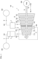
FIG. 1 is a schematic configuration diagram of a steam turbine according to an embodiment of the present disclosure. -
FIG. 2 is a schematic cross-sectional view of a valve device according to the embodiment of the present disclosure from one side. -
FIG. 3 is a perspective view showing a configuration of a part of the valve device according to the embodiment of the present disclosure. -
FIG. 4 is a view of a spring support of the valve device according to the embodiment of the present disclosure from an extension direction. - Hereinafter, an embodiment for implementing a steam turbine and a valve device according to the present disclosure will be described with reference to the accompanying drawings.
- As shown in
FIG. 1 , asteam turbine 100 includes a turbine main body 1, a main steam valve 2, an extraction valve 3 (valve device), and a main stop valve 4. - Steam V is supplied to the turbine main body 1 from a
steam supply source 200 such as a boiler. The turbine main body 1 includes aturbine casing 10 and aturbine rotor 11 that rotates within theturbine casing 10 by the steam V supplied into theturbine casing 10. - The
turbine casing 10 is formed of a casingmain body 10a, a plurality ofstator vane rows 10b, and apartition plate 10c. The casingmain body 10a covers theturbine rotor 11 from the outside. The casingmain body 10a forms a flow passage Ct through which the steam V flows together with theturbine rotor 11. Thestator vane rows 10b are integrally formed with the casingmain body 10a. - The
turbine rotor 11 is formed of a rotatingshaft 11a and a plurality ofrotor blade rows 11b. The rotatingshaft 11a is a rotatingshaft 11a that is rotatable around an axis Ar extending in a horizontal direction. Therotor blade rows 11b are integrally formed with the rotatingshaft 11a. - Hereinafter, a direction in which the axis Ar extends is simply referred to as an "axial direction Da". Further, one side (left side in
FIG. 1 ) in the axial direction Da is simply referred to as "one side Dal". The other side (right side inFIG. 1 ) in the axial direction Da is simply referred to as "the other side Dar". - Of directions orthogonal to the axis Ar, an up-down direction (up-down direction in
FIG. 2 ), which is perpendicular to the horizontal direction, is referred to as a "vertical direction Dv". Further, an upper side (upper side inFIG. 2 ) in the vertical direction Dv is referred to as an "upper side Dvu". An opposite side (lower side inFIG. 2 ) to the upper side Dvu in the vertical direction Dv is referred to as a "lower side Dvd". - Here, the
partition plate 10c is integrally formed with the casingmain body 10a. Thepartition plate 10c is disposed between thestator vane rows 10b in the axial direction Da. In the present embodiment, the plurality ofstator vane rows 10b are disposed on each of one side Dal and the other side Dar with thepartition plate 10c as a boundary. Thepartition plate 10c divides the inside of the flow passage Ct into two spaces in the axial direction Da, for example, together with a sealing device or the like (not shown) disposed between thepartition plate 10c and the rotatingshaft 11a. - The
stator vane rows 10b of theturbine casing 10 and therotor blade rows 11b of theturbine rotor 11 are alternately arranged in the axial direction Da. Rotation of theturbine rotor 11 is transmitted via the rotatingshaft 11a to acompressor 500 connected to the one side Dal of therotating shaft 11a, for example. Thecompressor 500 compresses a fluid, such as a gas, by being rotated by the rotatingshaft 11a. - The main stop valve 4 is a closing valve (trip and throttle valve (TTV)). The main steam valve 2 and the extraction valve 3 are composite valves in which a regulating valve (governing valve (GV)), a closing valve (trip and throttle valve (TTV)), and an overload valve are integrated. The main steam valve 2 and the main stop valve 4 are disposed on an inlet side of the one side Dal in the turbine main body 1. The main steam valve 2 and the main stop valve 4 regulate the amount of the steam V supplied to the turbine main body 1.
- A first
steam supply line 201 connected to thesteam supply source 200 and the main steam valve 2 are connected to the main stop valve 4. A secondsteam supply line 202 connected to the turbine main body 1 is connected to the main steam valve 2. The main steam valve 2 regulates the amount of the steam V supplied from thesteam supply source 200 through the firststeam supply line 201 and the main stop valve 4, and then supplies the steam V to the turbine main body 1 through the secondsteam supply line 202. - The main steam valve 2 may be directly connected to a suction port (not shown) that is an inlet of the turbine main body 1 by being integrally formed with the
turbine casing 10, not via the secondsteam supply line 202. - The extraction valve 3 is disposed closer to an outlet side of the other side Dar in the turbine main body 1 than the main steam valve 2 is. The extraction valve 3 extracts some of the steam V introduced into the turbine main body 1 and having worked on an upstream side (one side Dal) of the turbine main body 1. A cleaning liquid W is supplied to the extraction valve 3 from a cleaning
liquid supply source 300 in which the cleaning liquid W is stored. The extraction valve 3 supplies the supplied cleaning liquid W into the turbine main body 1, together with the extracted steam V. The extraction valve 3 may supply the extracted steam V to an external device other than the turbine main body 1. - An
extraction line 303 connected to the turbine main body 1 via an extractedsteam outlet 304 formed integrally with the turbine main body 1 and capable of extracting the steam V from the flow passage Ct, asteam line 302 connected to the turbine main body 1, and a cleaningliquid supply line 301 connected to the cleaningliquid supply source 300 are connected to the extraction valve 3. Theextraction line 303 is connected to the turbine main body 1 on the one side Dal with respect to thepartition plate 10c via the extractedsteam outlet 304. Thesteam line 302 is connected to the turbine main body 1 on the other side Dar with respect to thepartition plate 10c. - The extraction valve 3 may be directly connected to an extraction port of the turbine main body 1 by being integrally formed with the
turbine casing 10, not via theextraction line 303 and thesteam line 302. Hereinafter, in the present embodiment, the extraction valve 3 is simply referred to as a "valve device 3". - As shown in
FIGS. 2 and3 , the valve device 3 in the present embodiment includes avalve box 30, avalve body 34, aninner bar 36, arod 37, adrive mechanism 40, aspring support 41, aspring 45, aspring support portion 46, athermometer 38, and apressure gauge 39. - The
valve box 30 supplies the cleaning liquid W supplied from the cleaningliquid supply source 300 through the cleaningliquid supply line 301 into the turbine main body 1 through thesteam line 302, together with the steam V extracted through theextraction line 303. That is, a flow passage through which the steam V and the cleaning liquid W flow is formed inside thevalve box 30. Thevalve box 30 is disposed on the upper side Dvu with respect to the turbine main body 1. Thevalve box 30 includes a valve boxmain body 31, alid portion 32, avalve seat portion 33, and a cleaningnozzle 35. - The valve box
main body 31 is formed in a box shape. The valve boxmain body 31 is made of, for example, a metal or the like. Inside the valve boxmain body 31, aninlet flow passage 31a into which the steam V extracted from the turbine main body 1 flows, anoutlet flow passage 31b through which the steam V flows out, and a valve chamber R that connects theinlet flow passage 31a and theoutlet flow passage 31b are formed. InFIG. 2 , theinlet flow passage 31a is indicated by a two-dot chain line circle for want of space. The valve chamber R is defined by abottom surface 31d and aside surface 31e that form aninner surface 31i of the valve boxmain body 31. - The valve box
main body 31 is formed with anopening portion 31c that is open so as to open the valve chamber R at a position different from those of theinlet flow passage 31a and theoutlet flow passage 31b. The openingportion 31c in the present embodiment is formed in the valve boxmain body 31 such that theopening portion 31c faces the upper side Dvu. - The
inlet flow passage 31a is connected to theextraction line 303. Theinlet flow passage 31a is disposed on the one side Dal with respect to theoutlet flow passage 31b and opens into the valve chamber R on theside surface 31e disposed on the one side Dal in the valve boxmain body 31. Note that theside surface 31e on which theinlet flow passage 31a opens is not shown for want of space. Theoutlet flow passage 31b is connected to thesteam line 302. Here, theoutlet flow passage 31b is formed by thevalve seat portion 33 formed in a tubular shape, which is fixed to a bottom wall on the lower side Dvd in the valve boxmain body 31. Specifically, thevalve seat portion 33 forms theoutlet flow passage 31b by fitting into ahole 31f formed in the bottom wall of the valve boxmain body 31. The bottom wall has thebottom surface 31d facing the upper side Dvu. - A plurality of
valve seat portions 33 are disposed on the bottom wall of the valve boxmain body 31. In the present embodiment, fivevalve seat portions 33 are disposed on the bottom wall of the valve boxmain body 31. That is, fiveoutlet flow passages 31b are constituted by the inside of these fivevalve seat portions 33. Each of thevalve seat portions 33 is made of, for example, an elastic body. - The
lid portion 32 is formed in a plate shape. Thelid portion 32 is made of, for example, a metal or the like. Thelid portion 32 is attachable to and detachable from the valve boxmain body 31 and closes theopening portion 31c formed in the valve boxmain body 31 from the upper side Dvu. Thelid portion 32 has afront surface 32a facing the upper side Dvu and aback surface 32b facing a side opposite to thefront surface 32a. - The
lid portion 32 closes theopening portion 31c from the upper side Dvu, so that theback surface 32b of thelid portion 32 defines the valve chamber R, together with theinner surface 31i of the valve boxmain body 31. Thelid portion 32 in the present embodiment closes theopening portion 31c by being fixed to the valve boxmain body 31 with a plurality ofbolts 30a. Thelid portion 32 seals theopening portion 31c by being fixed to the valve boxmain body 31. - The cleaning
nozzle 35 is a nozzle capable of supplying the cleaning liquid W into the valve chamber R from the outside. A pair of cleaningnozzles 35 are disposed with respect to thelid portion 32 while penetrating thelid portion 32. A configuration of the cleaningnozzle 35 will be described below. - The
valve body 34 is disposed in the valve chamber R, and is capable of regulating a flow rate of the steam V flowing through theoutlet flow passage 31b by relative movement to theoutlet flow passage 31b. The number ofvalve bodies 34 disposed in the valve chamber R is the same as the number of theoutlet flow passages 31b. In the present embodiment, fivevalve bodies 34 are disposed in the valve chamber R. Thevalve body 34 is formed of ashaft portion 34a extending in the vertical direction Dv and a sealingportion 34b formed integrally with an end part on the lower side Dvd in theshaft portion 34a and abuttable on theoutlet flow passage 31b. The sealingportion 34b is made of, for example, an elastic body. As thevalve body 34 moves toward theoutlet flow passage 31b in the valve chamber R, the sealingportion 34b of thevalve body 34 abuts on thevalve seat portion 33. In this case, since thevalve seat portion 33 and the sealingportion 34b are made of an elastic body, the valve chamber R and theoutlet flow passage 31b are airtightly isolated. - The
inner bar 36 is formed in a columnar shape. Theinner bar 36 is made of, for example, a metal or the like. Theinner bar 36 is connected to a plurality of thevalve bodies 34, and is capable of simultaneously moving the plurality ofvalve bodies 34 in the valve chamber R. Therefore, theinner bar 36 integrates the plurality ofvalve bodies 34 in the valve chamber R. In the present embodiment, theshaft portion 34a of thevalve body 34 is fixed to theinner bar 36 while penetrating theinner bar 36. - The
rod 37 is formed in a columnar shape extending in the vertical direction Dv. Hereinafter, for convenience of description, a direction in which therod 37 extends will be referred to as an extension direction De. That is, in the present embodiment, the extension direction De matches the vertical direction Dv. Therod 37 is made of, for example, a metal or the like. Therod 37 is connected to theinner bar 36 by being disposed to penetrate thelid portion 32. Therod 37 moves theinner bar 36 relative to theoutlet flow passage 31b by relative movement to thelid portion 32 in the extension direction De. In the present embodiment, a pair ofrods 37 are connected to theinner bar 36. Hereinafter, for convenience of description, a direction in which the pair of rods are connected, that is, a direction in which the pair of rods are separated from each other (horizontal direction inFIG. 2 ), will be referred to as a "separation direction D1". - Here, the cleaning
nozzle 35 is disposed in a region between the pair ofrods 37 when viewed from the extension direction De in which therods 37 extend. The cleaningnozzle 35 is made of, for example, a metal or the like. The cleaningnozzle 35 includes apipe portion 35a extending in the vertical direction Dv, and anozzle portion 35b connected to an end part on the lower side Dvd of thepipe portion 35a. - The
pipe portion 35a is a pipe for guiding the cleaning liquid W supplied from the cleaningliquid supply source 300 into the valve chamber R. Thepipe portion 35a penetrates thelid portion 32 in the vertical direction Dv. That is, thepipe portion 35a penetrates thelid portion 32 in the extension direction De. Specifically, thepipe portion 35a penetrates the region between the pair ofrods 37 when viewed from the extension direction De in which therods 37 extend. One end of thepipe portion 35a is connected to the cleaning liquid supply line 301 (the connection is not shown), the other end of thepipe portion 35a is positioned in the valve chamber R. - The
nozzle portion 35b is a circular nozzle for injecting the cleaning liquid W guided by thepipe portion 35a into the valve chamber R. Thenozzle portion 35b is disposed in the valve chamber R. Thenozzle portion 35b is connected to the other end of thepipe portion 35a. Thenozzle portion 35b sprays the cleaning liquid W in a conical shape toward thebottom surface 31d of the valve boxmain body 31 in the valve chamber R. An apex angle of a cone when the cleaning liquid W sprayed by thenozzle portion 35b in the present embodiment spreads in a conical shape is, for example, 80° to 100°. - In the present embodiment, the
valve lid 25 is constituted by thelid portion 32 and the cleaningnozzle 35. - The
drive mechanism 40 moves therod 37 relative to thelid portion 32 in the vertical direction Dv. Thedrive mechanism 40 is disposed outside thevalve box 30. Thedrive mechanism 40 is formed of anactuator 400, apivot shaft 401, a pivotshaft support portion 402, a first connectingportion 403, and a second connectingportion 404. - The
actuator 400 includes ashaft 400b extending in the vertical direction Dv (extension direction De) and an actuatormain body 400a that moves theshaft 400b in the vertical direction Dv. The actuatormain body 400a is supported outside thevalve box 30 by a frame or the like (not shown). The actuatormain body 400a moves theshaft 400b in the vertical direction Dv by being controlled by an internal control device (not shown). - The
pivot shaft 401 is a member formed in a cylindrical shape. Thepivot shaft 401 is made of, for example, a metal or the like. An end part of thepivot shaft 401 is connected to theshaft 400b so as to be rotatable about a rotating axis O extending in the horizontal direction with the movement of theshaft 400b of theactuator 400. Thepivot shaft 401 in the present embodiment rotates about the rotating axis O. The rotating axis O and the axis Ar in the present embodiment are perpendicular to each other when viewed from the upper side Dvu. - The pivot
shaft support portion 402 rotatably supports thepivot shaft 401 from the lower side Dvd. The pivotshaft support portion 402 connects thefront surface 32a of thelid portion 32 and an outer peripheral surface of thepivot shaft 401. The pivotshaft support portion 402 is made of, for example, a metal or the like. In the present embodiment, a pair of the pivotshaft support portions 402 rotatably support thepivot shaft 401 from the lower side Dvd. - The first connecting
portion 403 is integrally fixed to thepivot shaft 401. The first connectingportion 403 rotates about the rotating axis O with the rotation of thepivot shaft 401. The first connectingportion 403 is formed in a plate shape that spreads in a flange shape with respect to thepivot shaft 401. That is, the first connectingportion 403 spreads in a direction perpendicular to the rotating axis O. The number of first connectingportions 403 disposed on thepivot shaft 401 is the same as the number of therods 37. That is, a pair of first connectingportions 403 are disposed on thepivot shaft 401. The first connectingportion 403 is made of, for example, a metal or the like. - The second connecting
portion 404 extends in the vertical direction Dv (extension direction De). As shown inFIG. 3 , the second connectingportion 404 connects a portion of the first connectingportion 403 on the one side Dal with respect to thepivot shaft 401 and an end part of therod 37 on the upper side Dvu. The second connectingportion 404 is connected to thefirst connection portion 403 so as to be movable in the vertical direction Dv with the rotation of the first connectingportion 403 about the rotating axis O. The second connectingportion 404 is made of, for example, a metal or the like. - As shown in
FIGS. 2 and3 , thespring support 41 is disposed outside thevalve box 30 and fixed to the pair ofrods 37. Thespring support 41 connects the pair ofrods 37 to each other. Thespring support 41 in the present embodiment is formed in a plate shape to connect the end parts on the upper side Dvu in therods 37. Thespring support 41 is made of, for example, a metal or the like. Thespring support 41 includes amain body portion 42 disposed between the pair ofrods 37, a fixedportion 43 integrally formed with themain body portion 42 and connecting themain body portion 42 and therods 37, and acover portion 44. - The
main body portion 42 is formed in a plate shape. Themain body portion 42 includes anupper surface 42c facing the upper side Dvu, a lower surface 42d facing an opposite side to theupper surface 42c, and a main bodyportion side surface 42e connecting theupper surface 42c and the lower surface 42d. The lower surface 42d faces thefront surface 32a of thelid portion 32 in the vertical direction Dv (extension direction De) while spaced from thefront surface 32a. The main bodyportion side surface 42e corresponds to a thickness of themain body portion 42 formed in a plate shape. As also shown inFIG. 4 , a pair of recessedportions 42a recessed from the main bodyportion side surface 42e facing the one side Dal toward the other side Dar are formed on themain body portion 42. - The fixed
portion 43 is formed in a plate shape. A pair of fixedportions 43 are formed integrally with themain body portion 42. Specifically, each of the pair of fixedportions 43 connects the main bodyportion side surface 42e of themain body portion 42 facing the separation direction D1 and an outer peripheral surface of therod 37. A thickness of the fixedportion 43 in the present embodiment is thinner than the thickness of themain body portion 42. - The
cover portion 44 is formed in a prism shape. Thecover portion 44 abuts on the main bodyportion side surface 42e of themain body portion 42 facing the one side Dal, from the one side Dal. In the present embodiment, a surface of thecover portion 44 that abuts on themain body portion 42 is anabutting surface 44a. Theabutting surface 44a abuts on the main bodyportion side surface 42e of themain body portion 42 facing the one side Dal, thereby forming aninsertion hole 41a. Therefore, a pair ofinsertion holes 41a are formed in thespring support 41 in the present embodiment. Thecover portion 44 is fixed to themain body portion 42 with a plurality ofcover bolts 44b. Here, as shown inFIGS. 2 to 4 , thepipe portion 35a of the cleaningnozzle 35 is inserted into theinsertion hole 41a of thespring support 41. - As shown in
FIG. 4 , a convexcurved surface 42b is formed on themain body portion 42. The convexcurved surface 42b is formed to gradually increase in a plate width direction D2 from end parts in the separation direction D1 in which the pair ofrods 37 are connected toward the center in the separation direction D1, when viewed from the extension direction De. The plate width direction D2 is a direction perpendicular to each of the extension direction De and the separation direction D1. The convexcurved surface 42b is connected to a pair of main bodyportion side surfaces 42e facing the separation direction D1. Thus, even when the recessedportion 42a constituting theinsertion hole 41a is formed in themain body portion 42, reduction in rigidity of themain body portion 42 can be suppressed. - The
spring 45 is a coil spring that biases thespring support 41 toward thelid portion 32. Thespring 45 is made of, for example, a metal or the like. As shown inFIGS. 2 and3 , thespring 45 is disposed outside thevalve box 30. Thespring 45 abuts on theupper surface 42c of thespring support 41 from the upper side Dvu (extension direction De). - The
spring support portion 46 supports thespring 45 on thespring support 41. Thespring support portion 46 is disposed outside thevalve box 30. Thespring support portion 46 is made of, for example, a metal or the like. Thespring support portion 46 includes afirst support portion 46a, asecond support portion 46b, and a connectingportion 46c. - The
first support portion 46a is formed in a columnar shape extending in the vertical direction Dv. Thefirst support portion 46a is disposed inside thespring 45. An end part on the lower side Dvd of thefirst support portion 46a is fixed to theupper surface 42c of themain body portion 42 of thespring support 41. An end part on the upper side Dvu of thefirst support portion 46a protrudes to the upper side Dvu with respect to an end part of the upper side Dvu of thespring 45. Hereinafter, for convenience of description, a portion of thefirst support portion 46a that protrudes to the upper side Dvu with respect to thespring 45 will be referred to as a "protrudingportion 46p" (seeFIG. 2 ). - The
second support portion 46b is formed in a columnar shape extending in the vertical direction Dv. Thesecond support portion 46b is disposed outside thespring 45. An end part on the lower side Dvd of thesecond support portion 46b is fixed to thefront surface 32a of thelid portion 32. - The connecting
portion 46c is a member that integrally connects thefirst support portion 46a and thesecond support portion 46b. The connectingportion 46c connects the protrudingportion 46p of thefirst support portion 46a and an end part on the upper side Dvu of thesecond support portion 46b. The connectingportion 46c is formed in a plate shape. The connectingportion 46c has afirst surface 46d facing the upper side Dvu and asecond surface 46e facing an opposite side to thefirst surface 46d. - Here, the end part on the upper side Dvu of the
spring 45 is connected to thesecond surface 46e of the connectingportion 46c. Thespring 45 is compressed between thesecond surface 46e of the connectingportion 46c and theupper surface 42c of thespring support 41. Thus, thespring 45 biases thespring support 41 toward thelid portion 32. In other words, the pair ofrods 37 integrally connected to thespring support 41, theinner bar 36 connected to the pair ofrods 37, and the plurality ofvalve bodies 34 connected to theinner bar 36 are each biased toward the lower side Dvd. - The
thermometer 38 is a sensor capable of measuring a temperature of the steam V in the valve chamber R. Thethermometer 38 is disposed with respect to thelid portion 32 while penetrating thelid portion 32. Thethermometer 38 in the present embodiment includes a probe, such as a thermocouple. Thethermometer 38 measures the temperature of the steam V in the valve chamber R by disposing the probe in the valve chamber R. - The
pressure gauge 39 is a sensor capable of measuring a pressure of the steam V in the valve chamber R. Thepressure gauge 39 is disposed with respect to thelid portion 32 while penetrating thelid portion 32. Thepressure gauge 39 measures the pressure of the steam V in the valve chamber R by extracting some of the steam V in the valve chamber R to the outside of thevalve box 30. - Here, the
thermometer 38 and thepressure gauge 39 are disposed with the pair ofrods 37 therebetween in the separation direction D1 in which the pair ofrods 37 are connected, when viewed from the extension direction De. - The
valve box 30 of the valve device 3 according to the above embodiment includes thelid portion 32 that is attachable to and detachable from the valve boxmain body 31 and closes theopening portion 31c, and the cleaningnozzle 35 disposed while penetrating thelid portion 32 and capable of supplying the cleaning liquid W into the valve chamber R from the outside. - Accordingly, for example, the cleaning
nozzle 35 can be attached to thevalve box 30 not including the cleaningnozzle 35 by replacing only thelid portion 32. In addition, for example, a size of the valve boxmain body 31 can be reduced compared with thevalve box 30 including the cleaningnozzle 35 penetrating the valve boxmain body 31. - Therefore, it is possible to reduce a size of the valve device 3 as a whole while suppressing the manufacturing and maintenance costs of the valve device 3. That is, it is possible to reduce the cost required for adding the function of supplying the cleaning liquid W into the flow passage Ct and to ensure maintainability.
- In addition, in the embodiment, the pair of
rods 37 are disposed with respect to thelid portion 32 while separated from each other, and the cleaningnozzle 35 is disposed in a region between the pair ofrods 37, when viewed from the extension direction De in which therods 37 extend. Here, since the pair ofrods 37 support theinner bar 36 such that theinner bar 36 is suspended from the upper side Dvu, therods 37 are disposed with respect to thelid portion 32 in a well-balanced manner so as to be symmetrical in the separation direction D1, when viewed from the extension direction De. - Thus, the cleaning liquid W supplied from the cleaning
nozzle 35 is supplied into the valve chamber R from between the pair ofrods 37. That is, the cleaning liquid W is supplied into the valve chamber R from the more central side of thelid portion 32 by the cleaningnozzle 35. Therefore, it is possible to reduce the thermal influence that the cleaning liquid W supplied into the valve chamber R receives from the valve boxmain body 31 in the valve chamber R. - In addition, in the embodiment, the
thermometer 38 and thepressure gauge 39 are disposed to penetrate thelid portion 32, and thethermometer 38 and thepressure gauge 39 are disposed with respect to thelid portion 32 with the pair ofrods 37 therebetween in the separation direction D1 in which the pair ofrods 37 are connected, when viewed from the extension direction De. - Thus, at least the
rod 37 is interposed between the cleaningnozzle 35 and thethermometer 38 and between the cleaningnozzle 35 and thepressure gauge 39 in thelid portion 32. For this reason, compared with a case where therod 37 is not interposed, measurement results of thethermometer 38 and thepressure gauge 39 when the cleaning liquid W is supplied into the valve chamber R can be restrained from being affected by the cleaning liquid W. In addition, for example, when an abnormality occurs in one or more of thethermometer 38 and thepressure gauge 39, one or more of thethermometer 38 and thepressure gauge 39 can be easily maintained by removing only thelid portion 32. - In the embodiment, since the
spring support 41 is pressed by thespring 45, when thevalve body 34 seals theoutlet flow passage 31b through which the steam V flows between the valve chamber R and the flow passage Ct, backflow of the steam V from the flow passage Ct to the valve chamber R can be suppressed. In addition, in the embodiment, thespring support 41 is pressed by thespring 45 to offset force exerted on therod 37 in the vertical direction Dv due to a pressure difference. Further, thespring support 41 includes theinsertion hole 41a through which the cleaningnozzle 35 is inserted. Thus, it is possible to suppress an increase in size of thelid portion 32. - While preferred embodiments of the invention have been described and illustrated above, it should be understood that these are exemplary of the invention and are not to be considered as limiting. Additions, omissions, substitutions, and other modifications can be made without departing from the scope of the invention. Accordingly, the invention is not to be considered as being limited by the foregoing description and is only limited by the scope of the appended claims.
- A configuration of the valve device 3 may be applied to the main steam valve 2.
- In the embodiment, the configuration in which the
valve box 30 of the valve device 3 is disposed on the upper side Dvu with respect to the turbine main body 1 has been described, but the present invention is not limited to this configuration. In this case, the extension direction De and the vertical direction Dv need not match each other. For example, thevalve box 30 may be disposed laterally or obliquely with respect to the turbine main body 1. - In the embodiment, the configuration in which a pair of the
cleaning nozzles 35 are disposed with respect to thelid portion 32 has been described, but the present invention is not limited to this configuration. That is, thevalve box 30 may include onecleaning nozzle 35. Alternatively, thevalve box 30 may include three ormore cleaning nozzles 35. - In the embodiment, the configuration in which the
nozzle portion 35b of the cleaningnozzle 35 sprays the cleaning liquid W in a conical shape toward thebottom surface 31d in the valve boxmain body 31 in the valve chamber R has been described, but the present invention is not limited to this configuration. Thenozzle portion 35b may be angled to hit a predetermined location on theinner surface 31i of thevalve box 30, for example. In addition, thepipe portion 35a of the cleaningnozzle 35 may extend in the extension direction De toward thebottom surface 31d in the valve chamber R, and thenozzle portion 35b may be disposed in the vicinity of theinner bar 36. - The valve device according to the embodiment can be understood as follows, for example.
- (1) A valve device 3 according to a first aspect includes: a
valve box 30 in which aninlet flow passage 31a into which steam V flows and anoutlet flow passage 31b through which the steam V flows are formed, and in which a valve chamber R that connects theinlet flow passage 31a and theoutlet flow passage 31b is formed; and a plurality ofvalve bodies 34 configured to regulate a flow rate of the steam V flowing through theoutlet flow passage 31b by relative movement to theoutlet flow passage 31b, in which thevalve box 30 includes a valve boxmain body 31 in which theinlet flow passage 31a, theoutlet flow passage 31b, and anopening portion 31c are formed, alid portion 32 that is attachable to and detachable from the valve boxmain body 31 and is configured to close the openingportion 31c, and a cleaningnozzle 35 that is disposed to penetrate through thelid portion 32 and is configured to supply a cleaning liquid W into the valve chamber R from an outside. - Accordingly, for example, the cleaning
nozzle 35 can be attached to thevalve box 30 not including the cleaningnozzle 35 by replacing only thelid portion 32. In addition, for example, a size of the valve boxmain body 31 can be reduced compared with thevalve box 30 including the cleaningnozzle 35 penetrating the valve boxmain body 31. - (2) A valve device 3 according to a second aspect is the valve device 3 according to (1), further including: an
inner bar 36 that is connected to the plurality ofvalve bodies 34 and is configured to simultaneously move the plurality ofvalve bodies 34 in the valve chamber R; and a pair ofrods 37 that are disposed to penetrate thelid portion 32 and are connected to theinner bar 36, the pair ofrods 37 are configured to move theinner bar 36 relative to theoutlet flow passage 31b by relative movement to thelid portion 32, in which the pair ofrods 37 may be disposed with respect to thelid portion 32 at a distance from each other, and the cleaningnozzle 35 may be disposed in a region between the pair ofrods 37 when viewed from an extension direction De in which each of the pair ofrods 37 extends. - Thus, the cleaning liquid W supplied from the cleaning
nozzle 35 is supplied into the valve chamber R from between the pair ofrods 37. That is, the cleaning liquid W is supplied into the valve chamber R from the more central side of thelid portion 32 by the cleaningnozzle 35. - (3) A valve device 3 according to a third aspect is the valve device 3 according to (2), further including: a
thermometer 38 that is disposed to penetrate thelid portion 32 and is configured to measure a temperature of the steam V in the valve chamber R; and apressure gauge 39 that is disposed to penetrate thelid portion 32 and is configured to measure a pressure of the steam V in the valve chamber R, in which thethermometer 38 and thepressure gauge 39 may be disposed with respect to thelid portion 32 with the pair ofrods 37 therebetween in a separation direction D1 connecting the pair ofrods 37, when viewed from the extension direction De. - Thus, at least the
rod 37 is interposed between the cleaningnozzle 35 and thethermometer 38 and between the cleaningnozzle 35 and thepressure gauge 39 in thelid portion 32. For this reason, compared with a case where therod 37 is not interposed, measurement results of thethermometer 38 and thepressure gauge 39 when the cleaning liquid W is supplied into the valve chamber R can be prevented from being affected by the cleaning liquid W. - (4) A valve device 3 according to a fourth aspect is the valve device 3 according to (2) or (3), further including: a
drive mechanism 40 that is disposed outside thevalve box 30 and configured to move the pair ofrods 37 back and forth; aspring support 41 that has a plate shape, is disposed outside thevalve box 30, and is fixed to the pair ofrods 37, thespring support 41 connecting the pair ofrods 37 to each other; and aspring 45 that is disposed outside thevalve box 30 and biases thespring support 41 toward thelid portion 32 while abutting on thespring support 41, in which thespring support 41 may have aninsertion hole 41a through which the cleaningnozzle 35 is inserted. - Thus, since the
spring support 41 is pressed by thespring 45, when thevalve body 34 seals theoutlet flow passage 31b, backflow of the steam V to the valve chamber R can be suppressed. Further, since a part of the cleaningnozzle 35 is accommodated in the recessedportion 42a of thespring support 41, an increase in size of thelid portion 32 can be suppressed. - (5) A
valve lid 25 according to a fifth aspect includes: alid portion 32 that is attachable to and detachable from avalve box 30 including a valve chamber R and is configured to close anopening portion 31c of thevalve box 30; and a cleaningnozzle 35 that is disposed to penetrate thelid portion 32 and is configured to supply a cleaning liquid W into the valve chamber R from an outside. - According to the present disclosure, it is possible to provide a valve device and a valve lid that can reduce a cost required for adding a function of supplying a cleaning liquid into a steam turbine and ensure maintainability.
-
- 1: Turbine main body
- 2: Main steam valve
- 3: Valve device
- 4: Main stop valve
- 10: Turbine casing
- 10a: Casing main body
- 10b: Stator vane rows
- 10c: Partition plate
- 11: Turbine rotor
- 11a: Rotating shaft
- 11b: Rotor blade row
- 25: Valve lid
- 30: Valve box
- 30a: Bolt
- 31: Valve box main body
- 31a: Inlet flow passage
- 31b: Outlet flow passage
- 31c: Opening portion
- 31d: Bottom surface
- 31e: Side surface
- 31f: Hole
- 31i: Inner surface
- 32: Lid portion
- 32a: Front surface
- 32b: Back surface
- 33: Valve seat portion
- 34: Valve body
- 34a: Shaft portion
- 34b: Sealing portion
- 35: Cleaning nozzle
- 35a: Pipe portion
- 35b: Nozzle portion
- 36: Inner bar
- 37: Rod
- 38: Thermometer
- 39: Pressure gauge
- 40: Drive mechanism
- 41: Spring support
- 41a: Insertion hole
- 42: Main body portion
- 42a: Recessed portion
- 42b: Convex curved surface
- 42c: Upper surface
- 42d: Lower surface
- 42e: Main body portion side surface
- 43: Fixed portion
- 44: Cover portion
- 44a: Abutting surface
- 44b: Cover bolt
- 45: Spring
- 46: Spring support portion
- 46a: First support portion
- 46b: Second support portion
- 46c: Connecting portion
- 46d: First surface
- 46e: Second surface
- 46p: Protruding portion
- 100: Steam turbine
- 200: Steam supply source
- 201: First steam supply line
- 202: Second steam supply line
- 300: Cleaning liquid supply source
- 301: Cleaning liquid supply line
- 302: Steam line
- 303: Extraction line
- 304: Extracted steam outlet
- 400: Actuator
- 400a: Actuator main body
- 400b: Shaft
- 401: Pivot shaft
- 402: pivot shaft support portion
- 403: First connecting portion
- 404: Second connecting portion
- 500: Compressor
- Ar: Axis
- Ct: Flow passage
- D1: Separation direction
- D2: Plate width direction
- Da: Axial direction
- Dal: One side
- Dar: Other side
- De: Extension direction
- Dv: Vertical direction
- Dvd: Lower side
- Dvu: Upper side
- O: Rotating axis
- R: Valve chamber
- V: Steam
- W: Cleaning liquid
Claims (5)
- A valve device comprising:a valve box in which an inlet flow passage into which steam flows and an outlet flow passage through which the steam flows are formed, and in which a valve chamber that connects the inlet flow passage and the outlet flow passage is formed; anda plurality of valve bodies configured to regulate a flow rate of the steam flowing through the outlet flow passage by relative movement to the outlet flow passage,wherein the valve box includesa valve box main body in which the inlet flow passage, the outlet flow passage, and an opening portion are formed,a lid portion that is attachable to and detachable from the valve box main body and is configured to close the opening portion, anda cleaning nozzle that is disposed to penetrate through the lid portion and is configured to supply a cleaning liquid into the valve chamber from an outside.
- The valve device according to Claim 1, further comprising:an inner bar that is connected to the plurality of valve bodies and is configured to simultaneously move the plurality of valve bodies in the valve chamber; anda pair of rods that are disposed to penetrate the lid portion and are connected to the inner bar, the pair of rods are configured to move the inner bar relative to the outlet flow passage by relative movement to the lid portion,wherein the pair of rods are disposed with respect to the lid portion at a distance from each other, andthe cleaning nozzle is disposed in a region between the pair of rods, when viewed from an extension direction in which each of the pair of rods extends.
- The valve device according to Claim 2, further comprising:a thermometer that is disposed to penetrate the lid portion and is configured to measure a temperature of the steam in the valve chamber; anda pressure gauge that is disposed to penetrate the lid portion and is configured to measure a pressure of the steam in the valve chamber,wherein the thermometer and the pressure gauge are disposed with respect to the lid portion with the pair of rods therebetween in a separation direction connecting the pair of rods, when viewed from the extension direction.
- The valve device according to Claim 2 or 3, further comprising:a drive mechanism that is disposed outside the valve box and configured to move the pair of rods back and forth;a spring support that has a plate shape, is disposed outside the valve box, and is fixed to the pair of rods, the spring support connecting the pair of rods to each other; anda spring that is disposed outside the valve box and biases the spring support toward the lid portion while abutting on the spring support,wherein the spring support has an insertion hole through which the cleaning nozzle is inserted.
- A valve lid comprising:a lid portion that is attachable to and detachable from a valve box including a valve chamber and is configured to close an opening portion of the valve box; anda cleaning nozzle that is disposed to penetrate the lid portion and is configured to supply a cleaning liquid into the valve chamber from an outside.
Applications Claiming Priority (1)
| Application Number | Priority Date | Filing Date | Title |
|---|---|---|---|
| JP2022027482A JP7833906B2 (en) | 2022-02-25 | 2022-02-25 | Valve device and valve cover |
Publications (2)
| Publication Number | Publication Date |
|---|---|
| EP4234890A1 true EP4234890A1 (en) | 2023-08-30 |
| EP4234890B1 EP4234890B1 (en) | 2025-04-02 |
Family
ID=85321224
Family Applications (1)
| Application Number | Title | Priority Date | Filing Date |
|---|---|---|---|
| EP23157741.2A Active EP4234890B1 (en) | 2022-02-25 | 2023-02-21 | Steam valve device with cleaning nozzle |
Country Status (3)
| Country | Link |
|---|---|
| US (1) | US11913347B2 (en) |
| EP (1) | EP4234890B1 (en) |
| JP (1) | JP7833906B2 (en) |
Families Citing this family (1)
| Publication number | Priority date | Publication date | Assignee | Title |
|---|---|---|---|---|
| JP2025075375A (en) * | 2023-10-31 | 2025-05-15 | 三菱重工コンプレッサ株式会社 | Chemical plant compressor train |
Citations (10)
| Publication number | Priority date | Publication date | Assignee | Title |
|---|---|---|---|---|
| US4850793A (en) * | 1987-10-13 | 1989-07-25 | Westinghouse Electric Corp. | Steam chest modifications for improved turbine operations |
| US5018355A (en) * | 1989-08-28 | 1991-05-28 | Foster Charles D | Method and apparatus for periodic chemical cleanings of turbines |
| US5938402A (en) * | 1996-12-11 | 1999-08-17 | Asea Brown Boveri Ag | Axial turbine of a turbocharger |
| US6311704B1 (en) * | 2000-03-03 | 2001-11-06 | Hydrochem Industrial Services | Methods and apparatus for chemically cleaning turbines |
| US6550487B1 (en) * | 2000-03-09 | 2003-04-22 | Steris Inc. | Apparatus for removing deposits from enclosed chambers |
| US20150345710A1 (en) * | 2014-05-29 | 2015-12-03 | Kabushiki Kaisha Toshiba | Steam valve driving device and steam valve |
| JP2016183608A (en) | 2015-03-26 | 2016-10-20 | 三菱日立パワーシステムズ株式会社 | Steam valve device |
| CN206796156U (en) * | 2017-06-08 | 2017-12-26 | 师宗彩湖建材有限责任公司 | A kind of energy-saving still kettle of energy recycling heat energy |
| EA029411B1 (en) * | 2016-07-19 | 2018-03-30 | Белорусский Национальный Технический Университет | Device for cleaning and sterilization of medical tools |
| EP3517740A1 (en) * | 2018-01-30 | 2019-07-31 | Mitsubishi Heavy Industries Compressor Corporation | Valve device for turbine and method for producing valve device for a turbine |
-
2022
- 2022-02-25 JP JP2022027482A patent/JP7833906B2/en active Active
-
2023
- 2023-02-21 EP EP23157741.2A patent/EP4234890B1/en active Active
- 2023-02-22 US US18/172,528 patent/US11913347B2/en active Active
Patent Citations (10)
| Publication number | Priority date | Publication date | Assignee | Title |
|---|---|---|---|---|
| US4850793A (en) * | 1987-10-13 | 1989-07-25 | Westinghouse Electric Corp. | Steam chest modifications for improved turbine operations |
| US5018355A (en) * | 1989-08-28 | 1991-05-28 | Foster Charles D | Method and apparatus for periodic chemical cleanings of turbines |
| US5938402A (en) * | 1996-12-11 | 1999-08-17 | Asea Brown Boveri Ag | Axial turbine of a turbocharger |
| US6311704B1 (en) * | 2000-03-03 | 2001-11-06 | Hydrochem Industrial Services | Methods and apparatus for chemically cleaning turbines |
| US6550487B1 (en) * | 2000-03-09 | 2003-04-22 | Steris Inc. | Apparatus for removing deposits from enclosed chambers |
| US20150345710A1 (en) * | 2014-05-29 | 2015-12-03 | Kabushiki Kaisha Toshiba | Steam valve driving device and steam valve |
| JP2016183608A (en) | 2015-03-26 | 2016-10-20 | 三菱日立パワーシステムズ株式会社 | Steam valve device |
| EA029411B1 (en) * | 2016-07-19 | 2018-03-30 | Белорусский Национальный Технический Университет | Device for cleaning and sterilization of medical tools |
| CN206796156U (en) * | 2017-06-08 | 2017-12-26 | 师宗彩湖建材有限责任公司 | A kind of energy-saving still kettle of energy recycling heat energy |
| EP3517740A1 (en) * | 2018-01-30 | 2019-07-31 | Mitsubishi Heavy Industries Compressor Corporation | Valve device for turbine and method for producing valve device for a turbine |
Also Published As
| Publication number | Publication date |
|---|---|
| EP4234890B1 (en) | 2025-04-02 |
| JP2023123967A (en) | 2023-09-06 |
| US11913347B2 (en) | 2024-02-27 |
| JP7833906B2 (en) | 2026-03-23 |
| US20230272722A1 (en) | 2023-08-31 |
Similar Documents
| Publication | Publication Date | Title |
|---|---|---|
| US7650908B2 (en) | Valve assembly and related arrangements | |
| EP4234890B1 (en) | Steam valve device with cleaning nozzle | |
| US11156151B2 (en) | Regulating device for an exhaust turbocharger | |
| US8522820B2 (en) | Valve system with circumferentially oriented flow | |
| EP3425275B1 (en) | Flexure seal for fuel injection nozzle | |
| US9964963B2 (en) | Pressure equalizing insert | |
| CN108626404A (en) | Valve with whole machine balancing access | |
| CN206221689U (en) | Regulating valve for controlling the flow of fluid of technique productions equipment | |
| JP5611005B2 (en) | Adjustable and combined steam valves for steam turbines | |
| US11746910B2 (en) | Plug integrated staged valve trim assembly and fluid control valve comprising same | |
| BR112016006864B1 (en) | VALVE | |
| US20200271009A1 (en) | Valve device and steam turbine | |
| US7093484B2 (en) | Calibrating device for a water meter | |
| CN111655994B (en) | Intake valve and fuel gas supply assembly with leak-proof flow path | |
| CN102686460A (en) | Solenoid valve and driver assistance device having such a solenoid valve | |
| CN217029032U (en) | Turbine sealing device and gas turbine | |
| EP3256713B1 (en) | A fuel supply element configured to be used in a fuel supply pipe system of an internal combustion piston engine and a fuel supply pipe system | |
| JP5901934B2 (en) | steam trap | |
| JP6734060B2 (en) | Sensors and rotating machines | |
| CN102369381B (en) | Actuator adapter plate | |
| CN106640202B (en) | Shaft seal device of high-temperature steam screw machine and pressure control method thereof | |
| CN220185419U (en) | A centrifugal compressor and ammonia synthesis device | |
| JP4625026B2 (en) | Integrated post-guide valve seat ring assembly | |
| CN105745479A (en) | System for regulating a liquid in a circuit | |
| US12313173B2 (en) | Enhanced low noise, low leakage relief valve |
Legal Events
| Date | Code | Title | Description |
|---|---|---|---|
| PUAI | Public reference made under article 153(3) epc to a published international application that has entered the european phase |
Free format text: ORIGINAL CODE: 0009012 |
|
| STAA | Information on the status of an ep patent application or granted ep patent |
Free format text: STATUS: THE APPLICATION HAS BEEN PUBLISHED |
|
| AK | Designated contracting states |
Kind code of ref document: A1 Designated state(s): AL AT BE BG CH CY CZ DE DK EE ES FI FR GB GR HR HU IE IS IT LI LT LU LV MC ME MK MT NL NO PL PT RO RS SE SI SK SM TR |
|
| STAA | Information on the status of an ep patent application or granted ep patent |
Free format text: STATUS: REQUEST FOR EXAMINATION WAS MADE |
|
| 17P | Request for examination filed |
Effective date: 20240216 |
|
| RBV | Designated contracting states (corrected) |
Designated state(s): AL AT BE BG CH CY CZ DE DK EE ES FI FR GB GR HR HU IE IS IT LI LT LU LV MC ME MK MT NL NO PL PT RO RS SE SI SK SM TR |
|
| STAA | Information on the status of an ep patent application or granted ep patent |
Free format text: STATUS: EXAMINATION IS IN PROGRESS |
|
| 17Q | First examination report despatched |
Effective date: 20240508 |
|
| GRAP | Despatch of communication of intention to grant a patent |
Free format text: ORIGINAL CODE: EPIDOSNIGR1 |
|
| STAA | Information on the status of an ep patent application or granted ep patent |
Free format text: STATUS: GRANT OF PATENT IS INTENDED |
|
| INTG | Intention to grant announced |
Effective date: 20241004 |
|
| GRAS | Grant fee paid |
Free format text: ORIGINAL CODE: EPIDOSNIGR3 |
|
| GRAA | (expected) grant |
Free format text: ORIGINAL CODE: 0009210 |
|
| STAA | Information on the status of an ep patent application or granted ep patent |
Free format text: STATUS: THE PATENT HAS BEEN GRANTED |
|
| RAP3 | Party data changed (applicant data changed or rights of an application transferred) |
Owner name: MITSUBISHI HEAVY INDUSTRIES COMPRESSOR CORPORATION |
|
| AK | Designated contracting states |
Kind code of ref document: B1 Designated state(s): AL AT BE BG CH CY CZ DE DK EE ES FI FR GB GR HR HU IE IS IT LI LT LU LV MC ME MK MT NL NO PL PT RO RS SE SI SK SM TR |
|
| REG | Reference to a national code |
Ref country code: GB Ref legal event code: FG4D |
|
| REG | Reference to a national code |
Ref country code: CH Ref legal event code: EP |
|
| REG | Reference to a national code |
Ref country code: IE Ref legal event code: FG4D |
|
| REG | Reference to a national code |
Ref country code: DE Ref legal event code: R096 Ref document number: 602023002648 Country of ref document: DE |
|
| REG | Reference to a national code |
Ref country code: NL Ref legal event code: MP Effective date: 20250402 |
|
| PG25 | Lapsed in a contracting state [announced via postgrant information from national office to epo] |
Ref country code: NL Free format text: LAPSE BECAUSE OF FAILURE TO SUBMIT A TRANSLATION OF THE DESCRIPTION OR TO PAY THE FEE WITHIN THE PRESCRIBED TIME-LIMIT Effective date: 20250402 |
|
| REG | Reference to a national code |
Ref country code: AT Ref legal event code: MK05 Ref document number: 1781441 Country of ref document: AT Kind code of ref document: T Effective date: 20250402 |
|
| PG25 | Lapsed in a contracting state [announced via postgrant information from national office to epo] |
Ref country code: FI Free format text: LAPSE BECAUSE OF FAILURE TO SUBMIT A TRANSLATION OF THE DESCRIPTION OR TO PAY THE FEE WITHIN THE PRESCRIBED TIME-LIMIT Effective date: 20250402 Ref country code: PT Free format text: LAPSE BECAUSE OF FAILURE TO SUBMIT A TRANSLATION OF THE DESCRIPTION OR TO PAY THE FEE WITHIN THE PRESCRIBED TIME-LIMIT Effective date: 20250804 Ref country code: ES Free format text: LAPSE BECAUSE OF FAILURE TO SUBMIT A TRANSLATION OF THE DESCRIPTION OR TO PAY THE FEE WITHIN THE PRESCRIBED TIME-LIMIT Effective date: 20250402 |
|
| REG | Reference to a national code |
Ref country code: LT Ref legal event code: MG9D |
|
| PG25 | Lapsed in a contracting state [announced via postgrant information from national office to epo] |
Ref country code: GR Free format text: LAPSE BECAUSE OF FAILURE TO SUBMIT A TRANSLATION OF THE DESCRIPTION OR TO PAY THE FEE WITHIN THE PRESCRIBED TIME-LIMIT Effective date: 20250703 Ref country code: NO Free format text: LAPSE BECAUSE OF FAILURE TO SUBMIT A TRANSLATION OF THE DESCRIPTION OR TO PAY THE FEE WITHIN THE PRESCRIBED TIME-LIMIT Effective date: 20250702 |
|
| PG25 | Lapsed in a contracting state [announced via postgrant information from national office to epo] |
Ref country code: PL Free format text: LAPSE BECAUSE OF FAILURE TO SUBMIT A TRANSLATION OF THE DESCRIPTION OR TO PAY THE FEE WITHIN THE PRESCRIBED TIME-LIMIT Effective date: 20250402 |
|
| PG25 | Lapsed in a contracting state [announced via postgrant information from national office to epo] |
Ref country code: BG Free format text: LAPSE BECAUSE OF FAILURE TO SUBMIT A TRANSLATION OF THE DESCRIPTION OR TO PAY THE FEE WITHIN THE PRESCRIBED TIME-LIMIT Effective date: 20250402 |
|
| PG25 | Lapsed in a contracting state [announced via postgrant information from national office to epo] |
Ref country code: HR Free format text: LAPSE BECAUSE OF FAILURE TO SUBMIT A TRANSLATION OF THE DESCRIPTION OR TO PAY THE FEE WITHIN THE PRESCRIBED TIME-LIMIT Effective date: 20250402 |
|
| PG25 | Lapsed in a contracting state [announced via postgrant information from national office to epo] |
Ref country code: AT Free format text: LAPSE BECAUSE OF FAILURE TO SUBMIT A TRANSLATION OF THE DESCRIPTION OR TO PAY THE FEE WITHIN THE PRESCRIBED TIME-LIMIT Effective date: 20250402 |
|
| PG25 | Lapsed in a contracting state [announced via postgrant information from national office to epo] |
Ref country code: RS Free format text: LAPSE BECAUSE OF FAILURE TO SUBMIT A TRANSLATION OF THE DESCRIPTION OR TO PAY THE FEE WITHIN THE PRESCRIBED TIME-LIMIT Effective date: 20250702 |
|
| PG25 | Lapsed in a contracting state [announced via postgrant information from national office to epo] |
Ref country code: IS Free format text: LAPSE BECAUSE OF FAILURE TO SUBMIT A TRANSLATION OF THE DESCRIPTION OR TO PAY THE FEE WITHIN THE PRESCRIBED TIME-LIMIT Effective date: 20250802 |
|
| PG25 | Lapsed in a contracting state [announced via postgrant information from national office to epo] |
Ref country code: LV Free format text: LAPSE BECAUSE OF FAILURE TO SUBMIT A TRANSLATION OF THE DESCRIPTION OR TO PAY THE FEE WITHIN THE PRESCRIBED TIME-LIMIT Effective date: 20250402 |
|
| REG | Reference to a national code |
Ref country code: DE Ref legal event code: R097 Ref document number: 602023002648 Country of ref document: DE |
|
| PG25 | Lapsed in a contracting state [announced via postgrant information from national office to epo] |
Ref country code: SM Free format text: LAPSE BECAUSE OF FAILURE TO SUBMIT A TRANSLATION OF THE DESCRIPTION OR TO PAY THE FEE WITHIN THE PRESCRIBED TIME-LIMIT Effective date: 20250402 Ref country code: DK Free format text: LAPSE BECAUSE OF FAILURE TO SUBMIT A TRANSLATION OF THE DESCRIPTION OR TO PAY THE FEE WITHIN THE PRESCRIBED TIME-LIMIT Effective date: 20250402 |
|
| PG25 | Lapsed in a contracting state [announced via postgrant information from national office to epo] |
Ref country code: CZ Free format text: LAPSE BECAUSE OF FAILURE TO SUBMIT A TRANSLATION OF THE DESCRIPTION OR TO PAY THE FEE WITHIN THE PRESCRIBED TIME-LIMIT Effective date: 20250402 |
|
| PG25 | Lapsed in a contracting state [announced via postgrant information from national office to epo] |
Ref country code: EE Free format text: LAPSE BECAUSE OF FAILURE TO SUBMIT A TRANSLATION OF THE DESCRIPTION OR TO PAY THE FEE WITHIN THE PRESCRIBED TIME-LIMIT Effective date: 20250402 |
|
| PG25 | Lapsed in a contracting state [announced via postgrant information from national office to epo] |
Ref country code: SK Free format text: LAPSE BECAUSE OF FAILURE TO SUBMIT A TRANSLATION OF THE DESCRIPTION OR TO PAY THE FEE WITHIN THE PRESCRIBED TIME-LIMIT Effective date: 20250402 |
|
| PLBE | No opposition filed within time limit |
Free format text: ORIGINAL CODE: 0009261 |
|
| STAA | Information on the status of an ep patent application or granted ep patent |
Free format text: STATUS: NO OPPOSITION FILED WITHIN TIME LIMIT |
|
| REG | Reference to a national code |
Ref country code: CH Ref legal event code: L10 Free format text: ST27 STATUS EVENT CODE: U-0-0-L10-L00 (AS PROVIDED BY THE NATIONAL OFFICE) Effective date: 20260211 |
|
| 26N | No opposition filed |
Effective date: 20260105 |
|
| PGFP | Annual fee paid to national office [announced via postgrant information from national office to epo] |
Ref country code: DE Payment date: 20251230 Year of fee payment: 4 |
|
| PGFP | Annual fee paid to national office [announced via postgrant information from national office to epo] |
Ref country code: IT Payment date: 20260228 Year of fee payment: 4 |
|
| PG25 | Lapsed in a contracting state [announced via postgrant information from national office to epo] |
Ref country code: LT Free format text: LAPSE BECAUSE OF FAILURE TO SUBMIT A TRANSLATION OF THE DESCRIPTION OR TO PAY THE FEE WITHIN THE PRESCRIBED TIME-LIMIT Effective date: 20250402 |
|
| PG25 | Lapsed in a contracting state [announced via postgrant information from national office to epo] |
Ref country code: SE Free format text: LAPSE BECAUSE OF FAILURE TO SUBMIT A TRANSLATION OF THE DESCRIPTION OR TO PAY THE FEE WITHIN THE PRESCRIBED TIME-LIMIT Effective date: 20250402 |