EP4234889A1 - Casing assembly for gas turbine engine - Google Patents
Casing assembly for gas turbine engine Download PDFInfo
- Publication number
- EP4234889A1 EP4234889A1 EP23153187.2A EP23153187A EP4234889A1 EP 4234889 A1 EP4234889 A1 EP 4234889A1 EP 23153187 A EP23153187 A EP 23153187A EP 4234889 A1 EP4234889 A1 EP 4234889A1
- Authority
- EP
- European Patent Office
- Prior art keywords
- vane
- split
- casing
- rotational axis
- line flange
- Prior art date
- Legal status (The legal status is an assumption and is not a legal conclusion. Google has not performed a legal analysis and makes no representation as to the accuracy of the status listed.)
- Pending
Links
- 230000013011 mating Effects 0.000 claims description 34
- 239000000463 material Substances 0.000 description 19
- 238000004382 potting Methods 0.000 description 10
- 238000003466 welding Methods 0.000 description 9
- 238000000034 method Methods 0.000 description 7
- 230000008878 coupling Effects 0.000 description 6
- 238000010168 coupling process Methods 0.000 description 6
- 238000005859 coupling reaction Methods 0.000 description 6
- 238000004519 manufacturing process Methods 0.000 description 6
- 238000013016 damping Methods 0.000 description 5
- RTAQQCXQSZGOHL-UHFFFAOYSA-N Titanium Chemical compound [Ti] RTAQQCXQSZGOHL-UHFFFAOYSA-N 0.000 description 4
- 239000010936 titanium Substances 0.000 description 4
- 229910052719 titanium Inorganic materials 0.000 description 4
- 238000011144 upstream manufacturing Methods 0.000 description 4
- 238000002485 combustion reaction Methods 0.000 description 3
- 235000015250 liver sausages Nutrition 0.000 description 3
- 238000003754 machining Methods 0.000 description 3
- 230000001141 propulsive effect Effects 0.000 description 3
- 229910001148 Al-Li alloy Inorganic materials 0.000 description 2
- FCVHBUFELUXTLR-UHFFFAOYSA-N [Li].[AlH3] Chemical compound [Li].[AlH3] FCVHBUFELUXTLR-UHFFFAOYSA-N 0.000 description 2
- 239000004411 aluminium Substances 0.000 description 2
- 229910052782 aluminium Inorganic materials 0.000 description 2
- XAGFODPZIPBFFR-UHFFFAOYSA-N aluminium Chemical compound [Al] XAGFODPZIPBFFR-UHFFFAOYSA-N 0.000 description 2
- 239000002131 composite material Substances 0.000 description 2
- 230000006835 compression Effects 0.000 description 2
- 238000007906 compression Methods 0.000 description 2
- 239000000835 fiber Substances 0.000 description 2
- 238000005304 joining Methods 0.000 description 2
- 239000001989 lithium alloy Substances 0.000 description 2
- 230000014759 maintenance of location Effects 0.000 description 2
- 229910052751 metal Inorganic materials 0.000 description 2
- 239000002184 metal Substances 0.000 description 2
- OKTJSMMVPCPJKN-UHFFFAOYSA-N Carbon Chemical compound [C] OKTJSMMVPCPJKN-UHFFFAOYSA-N 0.000 description 1
- 229910000831 Steel Inorganic materials 0.000 description 1
- 229910045601 alloy Inorganic materials 0.000 description 1
- 239000000956 alloy Substances 0.000 description 1
- 230000000712 assembly Effects 0.000 description 1
- 238000000429 assembly Methods 0.000 description 1
- 230000009286 beneficial effect Effects 0.000 description 1
- 229910052799 carbon Inorganic materials 0.000 description 1
- 229910010293 ceramic material Inorganic materials 0.000 description 1
- 239000000446 fuel Substances 0.000 description 1
- 239000011159 matrix material Substances 0.000 description 1
- 239000011156 metal matrix composite Substances 0.000 description 1
- 239000000203 mixture Substances 0.000 description 1
- 229920001296 polysiloxane Polymers 0.000 description 1
- 230000001681 protective effect Effects 0.000 description 1
- 239000010959 steel Substances 0.000 description 1
Images








Classifications
-
- F—MECHANICAL ENGINEERING; LIGHTING; HEATING; WEAPONS; BLASTING
- F01—MACHINES OR ENGINES IN GENERAL; ENGINE PLANTS IN GENERAL; STEAM ENGINES
- F01D—NON-POSITIVE DISPLACEMENT MACHINES OR ENGINES, e.g. STEAM TURBINES
- F01D25/00—Component parts, details, or accessories, not provided for in, or of interest apart from, other groups
- F01D25/24—Casings; Casing parts, e.g. diaphragms, casing fastenings
-
- F—MECHANICAL ENGINEERING; LIGHTING; HEATING; WEAPONS; BLASTING
- F01—MACHINES OR ENGINES IN GENERAL; ENGINE PLANTS IN GENERAL; STEAM ENGINES
- F01D—NON-POSITIVE DISPLACEMENT MACHINES OR ENGINES, e.g. STEAM TURBINES
- F01D25/00—Component parts, details, or accessories, not provided for in, or of interest apart from, other groups
- F01D25/24—Casings; Casing parts, e.g. diaphragms, casing fastenings
- F01D25/243—Flange connections; Bolting arrangements
-
- F—MECHANICAL ENGINEERING; LIGHTING; HEATING; WEAPONS; BLASTING
- F01—MACHINES OR ENGINES IN GENERAL; ENGINE PLANTS IN GENERAL; STEAM ENGINES
- F01D—NON-POSITIVE DISPLACEMENT MACHINES OR ENGINES, e.g. STEAM TURBINES
- F01D9/00—Stators
- F01D9/02—Nozzles; Nozzle boxes; Stator blades; Guide conduits, e.g. individual nozzles
- F01D9/04—Nozzles; Nozzle boxes; Stator blades; Guide conduits, e.g. individual nozzles forming ring or sector
-
- F—MECHANICAL ENGINEERING; LIGHTING; HEATING; WEAPONS; BLASTING
- F01—MACHINES OR ENGINES IN GENERAL; ENGINE PLANTS IN GENERAL; STEAM ENGINES
- F01D—NON-POSITIVE DISPLACEMENT MACHINES OR ENGINES, e.g. STEAM TURBINES
- F01D9/00—Stators
- F01D9/02—Nozzles; Nozzle boxes; Stator blades; Guide conduits, e.g. individual nozzles
- F01D9/04—Nozzles; Nozzle boxes; Stator blades; Guide conduits, e.g. individual nozzles forming ring or sector
- F01D9/042—Nozzles; Nozzle boxes; Stator blades; Guide conduits, e.g. individual nozzles forming ring or sector fixing blades to stators
- F01D9/044—Nozzles; Nozzle boxes; Stator blades; Guide conduits, e.g. individual nozzles forming ring or sector fixing blades to stators permanently, e.g. by welding, brazing, casting or the like
-
- F—MECHANICAL ENGINEERING; LIGHTING; HEATING; WEAPONS; BLASTING
- F01—MACHINES OR ENGINES IN GENERAL; ENGINE PLANTS IN GENERAL; STEAM ENGINES
- F01D—NON-POSITIVE DISPLACEMENT MACHINES OR ENGINES, e.g. STEAM TURBINES
- F01D25/00—Component parts, details, or accessories, not provided for in, or of interest apart from, other groups
- F01D25/24—Casings; Casing parts, e.g. diaphragms, casing fastenings
- F01D25/26—Double casings; Measures against temperature strain in casings
- F01D25/265—Vertically split casings; Clamping arrangements therefor
-
- F—MECHANICAL ENGINEERING; LIGHTING; HEATING; WEAPONS; BLASTING
- F05—INDEXING SCHEMES RELATING TO ENGINES OR PUMPS IN VARIOUS SUBCLASSES OF CLASSES F01-F04
- F05D—INDEXING SCHEME FOR ASPECTS RELATING TO NON-POSITIVE-DISPLACEMENT MACHINES OR ENGINES, GAS-TURBINES OR JET-PROPULSION PLANTS
- F05D2220/00—Application
- F05D2220/30—Application in turbines
- F05D2220/32—Application in turbines in gas turbines
-
- F—MECHANICAL ENGINEERING; LIGHTING; HEATING; WEAPONS; BLASTING
- F05—INDEXING SCHEMES RELATING TO ENGINES OR PUMPS IN VARIOUS SUBCLASSES OF CLASSES F01-F04
- F05D—INDEXING SCHEME FOR ASPECTS RELATING TO NON-POSITIVE-DISPLACEMENT MACHINES OR ENGINES, GAS-TURBINES OR JET-PROPULSION PLANTS
- F05D2230/00—Manufacture
- F05D2230/20—Manufacture essentially without removing material
- F05D2230/23—Manufacture essentially without removing material by permanently joining parts together
- F05D2230/232—Manufacture essentially without removing material by permanently joining parts together by welding
-
- F—MECHANICAL ENGINEERING; LIGHTING; HEATING; WEAPONS; BLASTING
- F05—INDEXING SCHEMES RELATING TO ENGINES OR PUMPS IN VARIOUS SUBCLASSES OF CLASSES F01-F04
- F05D—INDEXING SCHEME FOR ASPECTS RELATING TO NON-POSITIVE-DISPLACEMENT MACHINES OR ENGINES, GAS-TURBINES OR JET-PROPULSION PLANTS
- F05D2240/00—Components
- F05D2240/10—Stators
- F05D2240/12—Fluid guiding means, e.g. vanes
-
- F—MECHANICAL ENGINEERING; LIGHTING; HEATING; WEAPONS; BLASTING
- F05—INDEXING SCHEMES RELATING TO ENGINES OR PUMPS IN VARIOUS SUBCLASSES OF CLASSES F01-F04
- F05D—INDEXING SCHEME FOR ASPECTS RELATING TO NON-POSITIVE-DISPLACEMENT MACHINES OR ENGINES, GAS-TURBINES OR JET-PROPULSION PLANTS
- F05D2240/00—Components
- F05D2240/10—Stators
- F05D2240/14—Casings or housings protecting or supporting assemblies within
-
- F—MECHANICAL ENGINEERING; LIGHTING; HEATING; WEAPONS; BLASTING
- F05—INDEXING SCHEMES RELATING TO ENGINES OR PUMPS IN VARIOUS SUBCLASSES OF CLASSES F01-F04
- F05D—INDEXING SCHEME FOR ASPECTS RELATING TO NON-POSITIVE-DISPLACEMENT MACHINES OR ENGINES, GAS-TURBINES OR JET-PROPULSION PLANTS
- F05D2250/00—Geometry
- F05D2250/30—Arrangement of components
- F05D2250/38—Arrangement of components angled, e.g. sweep angle
Definitions
- the present invention generally relates to gas turbine engines, more particularly, to a casing assembly for a turbine or a compressor of a gas turbine engine.
- a gas turbine engine generally includes a turbine and a compressor.
- Each of the turbine and the compressor includes a casing, and a stator and a rotor disposed within the casing.
- the stator may include a number of vanes that are coupled to the casing.
- the casing may be split axially into two halves along a horizontal plane. The two halves may be bolted together via mating flanges.
- the vanes may be connected to the casing using mechanical fasteners, such as, bolts.
- mechanical fasteners may increase a number of parts associated with the gas turbine engine, a cost associated with manufacturing of the gas turbine engine, and an overall weight of the gas turbine engine.
- conventional vane and casing assemblies may not have a robust design.
- it may be challenging to assemble the vane and casing assembly around the rotor which may increase a time and cost associated with an assembling of the gas turbine engine.
- the casing may include one or more shrouds that may be connected with the vanes of the stator.
- Such shrouds may include a number of shroud segments.
- adjacent shroud segments may be connected to each other by various joining techniques, such as, welding or using mechanical fasteners.
- joining techniques may require multiple machining and/or fabrication operations which may add to a manufacturing cost and may also introduce a risk of damage to other surrounding components, for example, if the mechanical fasteners get loose and escape into a main gas flow path.
- usage of mechanical fasteners to join adjacent shroud segments may increase the weight and cost associated with the gas turbine engine.
- the casing assembly of the present invention may be robust in design.
- the casing assembly may also be convenient to assemble around a rotor associated with a turbine or a compressor of the gas turbine engine, without compromising with a design of the rotor.
- the casing assembly may have a lower weight as the casing assembly may not require mechanical fasteners, such as bolts, for coupling of the stator vanes with the arcuate member.
- the casing assembly may be cost efficient due to usage of lower volume of materials for manufacturing of the casing assembly.
- the minimum circumferential clearance between the end stator vane and the split-line flange may eliminate an interference between the end stator vane and the corresponding split-line flange.
- the minimum circumferential clearance may further provide sufficient access for welding of the outer platform of the end stator vane with the arcuate member without any interference with the split-line flange.
- the casing assembly further includes at least one vane plate unit at least partially and circumferentially disposed between at least one split-line flange from the pair of split-line flanges of at least one vane casing segment from the plurality of vane casing segments and the adjacent split-line flange of the adjacent vane casing segment.
- the vane plate described herein may be used when a clearance between the end stator vanes of adjacent vane casing segments is such that it may be challenging to accommodate the split-line flanges therebetween.
- the vane plate unit includes a vane plate including a first mating surface at least partially engaging with the mating surface of the at least one split-line flange of the at least one vane casing segment and an opposing second mating surface at least partially engaging with the mating surface of the adjacent split-line flange of the adjacent vane casing segment.
- the vane plate is fixedly coupled to each of the at least one split-line flange and the adjacent split-line flange, such that the at least one split-line flange is fixedly coupled to the adjacent split-line flange via the vane plate.
- the vane plate is at least partially and circumferentially inclined relative to the rotational axis.
- the vane plate further includes at least one plate stator vane fixedly coupled to and extending at least radially from the vane plate.
- the at least one plate stator vane is circumferentially disposed between the proximal end stator vane of the at least one vane casing segment and the proximal end stator vane of the adjacent vane casing segment, such that the at least one row of stator vanes of the at least one vane casing segment, the at least one plate stator vane of the vane plate unit, and the at least one row of stator vanes of the adjacent vane casing segment together at least partially form a single circumferential row of stator vanes.
- the vane plate may be disposed such that a desired clearance may be maintained between the plate stator vane and the end stator vane of each of the adjacent vane casing segments.
- the vane plate has an angular extent about the rotational axis.
- the arcuate member of each vane casing segment has an angular extent about the rotational axis.
- the angular extent of each vane casing segment is greater than the angular extent of the vane plate by at least a factor of 20.
- the angular extent of the vane plate may be governed by a desired clearance between the end stator vanes of adjacent vane casing segments.
- the vane plate further includes an intersecting portion axially intersecting the single circumferential row of stator vanes. At least the intersecting portion of the vane plate, at least the intersecting portion of the at least one split-line flange of the at least one vane casing segment, and at least the intersecting portion of the adjacent split-line flange of the adjacent vane casing segment are circumferentially inclined relative to the rotational axis by a same circumferential angle. The circumferentially inclined intersecting portion of the vane plate may ensure that the plate stator vane is equidistantly disposed between each of the adjacent vane casing segments.
- the vane plate further includes at least one plate aperture.
- the at least one plate stator vane includes an aerofoil extending at least radially relative to the rotational axis from a radially inner end to a radially outer end, and an outer platform disposed at the radially outer end of the aerofoil.
- the outer platform is at least partially received within the at least one plate aperture of the vane plate.
- the outer platform of the at least one plate stator vane defines a chordal axis extending between opposing axial ends of the outer platform. The chordal axis is circumferentially inclined relative to the rotational axis by the same circumferential angle.
- the plate stator vane may either be integrally formed with the vane plate or the plate stator vane may be coupled to the vane plate by welding, thereby eliminating usage of additional components, such as, mechanical fasteners. Thus, additional weight and cost associated with such additional components may be eliminated.
- the plurality of vane casing segments includes at least three vane casing segments, such that the angular extent of the arcuate member of each of the at least three vane casing segments is less than 180 degrees about the rotational axis.
- the at least one vane plate unit includes at least three vane plate units, such that each of the at least three vane plate units is at least partially and circumferentially disposed between corresponding adjacent vane casing segments of the at least three vane casing segments.
- the three vane casing segments may allow easy assembly of the casing assembly around the rotor.
- the mating surface of at least one split-line flange from the pair of split-line flanges of at least one vane casing segment from the plurality of vane casing segments at least partially engages with the mating surface of the adjacent split-line flange of the adjacent vane casing segment, such that the at least one row of stator vanes of the at least one vane casing segment at least partially forms a single circumferential row of stator vanes, and wherein at least one split-line flange of the at least one vane casing segment is directly and fixedly coupled to the adjacent split-line flange of the adjacent vane casing segment.
- the arcuate member of the at least one vane casing segment has an angular extent of at most 180 degrees about the rotational axis.
- the arcuate member may allow easy assembly of the casing assembly around the rotor.
- the minimum circumferential clearance is from about 5 cm to about 10 cm. Such a range of the minimum circumferential clearance may eliminate any interference between the end stator vane and the corresponding split-line flange.
- At least the intersecting portion of at least one split-line flange of each vane casing segment is circumferentially inclined relative to the rotational axis by a circumferential angle.
- the outer platform of the end stator vane disposed adjacent to the at least one split-line flange defines a chordal axis extending between opposing axial ends of the outer platform.
- the chordal axis is circumferentially inclined relative to the rotational axis by the circumferential angle of the at least one split-line flange.
- the circumferentially inclined intersecting portion of the at least one split-line flange may ensure that the end stator vane of the vane casing segment is disposed at the minimum circumferential clearance from the at least one split-line flange. Further, the circumferentially inclined intersecting portion of the at least one split-line flange may ensure that the end stator vane does not interfere with the at least one split-line flange.
- the circumferential angle is from about 2 degrees to about 45 degrees. Such a range of the circumferential angle may eliminate any interference between the end stator vane and the at least one split-line flange.
- the at least one row of stator vanes further includes a plurality of rows of stator vanes axially spaced apart from each other relative to the rotational axis and fixedly coupled to the arcuate member.
- the at least one row of casing apertures further includes a plurality of rows of casing apertures corresponding to the plurality of rows of stator vanes.
- Each split-line flange further includes a plurality of intersecting portions disposed adjacent to a corresponding row of stator vanes from the plurality of rows of stator vanes. Further, at least one intersecting portion from the plurality of intersecting portions is circumferentially inclined relative to the rotational axis. The at least one circumferentially inclined intersecting portion may ensure that the end stator vane of the vane casing segment does not interfere with the corresponding split-line flange.
- each intersecting portion from the plurality of intersecting portions is circumferentially inclined relative to the rotational axis by a corresponding circumferential angle.
- the corresponding circumferential angles of at least two intersection portions from the plurality of intersection portions are different from each other.
- the different values of the circumferential angles may be based on different designs of the at least two rows of stator vanes corresponding to the at least two intersection portions.
- At least one of the plurality of intersecting portions extends parallel to the rotational axis. In such a case, a circumferential inclination of the at least one of the plurality of intersecting portions may not be required due to a design of the corresponding row of stator vanes.
- the casing assembly further includes a shroud radially spaced apart from the plurality of vane casing segments relative to the rotational axis.
- the shroud includes a plurality of shroud segments circumferentially arranged about the rotational axis and disposed adjacent to each other.
- Each shroud segment includes at least one row of shroud apertures circumferentially spaced apart from each other relative to the rotational axis.
- the radially inner end of the aerofoil of each stator vane of the at least one row of stator vanes is at least partially received within a corresponding shroud aperture of the at least one row of shroud apertures of a corresponding shroud segment from the plurality of shroud segments.
- Each stator vane may be therefore radially supported between the corresponding vane casing segment and shroud segments.
- each shroud segment and an adjacent shroud segment together form an interlocking arrangement that connects each shroud segment to the adjacent shroud segment.
- Such an interlocking arrangement may eliminate any axial movement of the shroud segments relative to the rotational axis. Further, the interlocking arrangement does not include any additional components, such as, mechanical fasteners, thereby eliminating a cost and weight associated with such additional components.
- the interlocking arrangement may provide improved vibration damping, seal clearance, and minimize leakage without incurring additional cost associated with fabricating and machining mating features.
- the interlocking arrangement includes at least one of a Z-shaped arrangement, a V-shaped arrangement with axial end portions, a V-shaped arrangement, and a zigzag arrangement. Such interlocking arrangements may eliminate any axial movement of the shroud segments relative to the rotational axis.
- the casing assembly further includes a potting material disposed in each shroud aperture of the at least one row of shroud apertures, such that the potting material surrounds the radially inner end of the aerofoil received within the corresponding shroud aperture and fixedly couples the radially inner end to the corresponding shroud segment.
- the potting material may provide retention and damping of the radially inner end of the aerofoil. Further, the potting material may also provide a rubbing surface for seal fins.
- a turbine or a compressor for a gas turbine engine the turbine or the compressor includes the casing assembly of the first aspect.
- a gas turbine engine that includes the casing assembly of the first aspect.
- gas turbine engines may comprise an engine core comprising a turbine, a combustor, a compressor, and a core shaft connecting the turbine to the compressor.
- gas turbine engines may comprise a fan (having fan blades) located upstream of the engine core.
- the gas turbine engine may comprise a gearbox that receives an input from the core shaft and outputs drive to the fan so as to drive the fan at a lower rotational speed than the core shaft.
- the input to the gearbox may be directly from the core shaft, or indirectly from the core shaft, for example, via a spur shaft and/or gear.
- the core shaft may rigidly connect the turbine and the compressor, such that the turbine and the compressor rotate at the same speed (with the fan rotating at a lower speed).
- the gas turbine engine as described and/or claimed herein may have any suitable general architecture.
- the gas turbine engine may have any desired number of shafts that connect turbines and compressors, for example, one, two, or three shafts.
- the turbine connected to the core shaft may be a first turbine
- the compressor connected to the core shaft may be a first compressor
- the core shaft may be a first core shaft.
- the engine core may further comprise a second turbine, a second compressor, and a second core shaft connecting the second turbine to the second compressor.
- the second turbine, the second compressor, and the second core shaft may be arranged to rotate at a higher rotational speed than the first core shaft.
- the second compressor may be positioned axially downstream of the first compressor.
- the second compressor may be arranged to receive (for example directly receive, for example via a generally annular duct) flow from the first compressor.
- the gearbox may be arranged to be driven by the core shaft that is configured to rotate (for example in use) at the lowest rotational speed (for example the first core shaft in the example above).
- the gearbox may be arranged to be driven only by the core shaft that is configured to rotate (for example in use) at the lowest rotational speed (for example only be the first core shaft, and not the second core shaft, in the example above).
- the gearbox may be arranged to be driven by any one or more shafts, for example, the first and/or second shafts in the example above.
- the gearbox may be a reduction gearbox (in that the output to the fan is a lower rotational rate than the input from the core shaft). Any type of gearbox may be used.
- the gearbox may be a "planetary” or “star” gearbox, as described in more detail elsewhere herein.
- the gearbox may have any desired reduction ratio (defined as the rotational speed of the input shaft divided by the rotational speed of the output shaft), for example greater than 2.5, for example in the range of from 3 to 4.2, or 3.2 to 3.8, for example on the order of or at least 3, 3.1, 3.2, 3.3, 3.4, 3.5, 3.6, 3.7, 3.8, 3.9, 4, 4.1 or 4.2.
- the gear ratio may be, for example, between any two of the values in the previous sentence.
- the gearbox may be a "star” gearbox having a ratio in the range of from 3.1 or 3.2 to 3.8. In some arrangements, the gear ratio may be outside these ranges.
- a combustor may be provided axially downstream of the fan and compressor(s).
- the combustor may be directly downstream of (for example at the exit of) the second compressor, where a second compressor is provided.
- the flow at the exit to the combustor may be provided to the inlet of the second turbine, where a second turbine is provided.
- the combustor may be provided upstream of the turbine(s).
- each compressor may comprise any number of stages, for example multiple stages.
- Each stage may comprise a row of rotor blades and a row of stator vanes, which may be variable stator vanes (in that their angle of incidence may be variable).
- the row of rotor blades and the row of stator vanes may be axially offset from each other.
- each turbine may comprise any number of stages, for example, multiple stages.
- Each stage may comprise a row of rotor blades and a row of stator vanes.
- the row of rotor blades and the row of stator vanes may be axially offset from each other.
- a fan blade and/or aerofoil portion of a fan blade described and/or claimed herein may be manufactured from any suitable material or combination of materials.
- at least a part of the fan blade and/or aerofoil may be manufactured at least in part from a composite, for example, a metal matrix composite and/or an organic matrix composite, such as carbon fibre.
- at least a part of the fan blade and/or aerofoil may be manufactured at least in part from a metal, such as, a titanium-based metal or an aluminium based material (such as an aluminium-lithium alloy) or a steel-based material.
- the fan blade may comprise at least two regions manufactured using different materials.
- the fan blade may have a protective leading edge, which may be manufactured using a material that is better able to resist impact (for example from birds, ice, or other material) than the rest of the blade.
- a leading edge may, for example, be manufactured using titanium or a titanium-based alloy.
- the fan blade may have a carbon-fibre or aluminium based body (such as an aluminium lithium alloy) with a titanium leading edge.
- a fan as described and/or claimed herein may comprise a central portion, from which the fan blades may extend, for example, in a radial direction.
- the fan blades may be attached to the central portion in any desired manner.
- each fan blade may comprise a fixture which may engage a corresponding slot in the hub (or disc).
- a fixture may be in the form of a dovetail that may slot into and/or engage a corresponding slot in the hub/disc in order to fix the fan blade to the hub/disc.
- the fan blades maybe formed integrally with a central portion. Such an arrangement may be referred to as a bladed disc or a bladed ring.
- any suitable method may be used to manufacture such a bladed disc or bladed ring.
- at least a part of the fan blades may be machined from a block and/or at least part of the fan blades may be attached to the hub/disc by welding, such as linear friction welding.
- variable area nozzle may allow the exit area of the bypass duct to be varied in use.
- the general principles of the present invention may apply to engines with or without a VAN.
- the fan of a gas turbine as described and/or claimed herein may have any desired number of fan blades, for example, 14, 16, 18, 20, 22, 24, or 26 fan blades.
- FIG. 1 illustrates a gas turbine engine 10 having a rotational axis 9.
- the engine 10 comprises an air intake 12 and a propulsive fan 23 that generates two airflows: a core airflow A and a bypass airflow B.
- the gas turbine engine 10 comprises a core 11 that receives the core airflow A.
- the engine core 11 comprises, in axial flow series, a low pressure compressor 14, a high pressure compressor 15, a combustion equipment 16, a high pressure turbine 17, a low pressure turbine 19, and a core exhaust nozzle 20.
- a nacelle 21 surrounds the gas turbine engine 10 and defines a bypass duct 22 and a bypass exhaust nozzle 18.
- the bypass airflow B flows through the bypass duct 22.
- the fan 23 is attached to and driven by the low pressure turbine 19 via a shaft 26 and an epicyclic gearbox 30.
- the core airflow A is accelerated and compressed by the low pressure compressor 14 and directed into the high pressure compressor 15 where further compression takes place.
- the compressed air exhausted from the high pressure compressor 15 is directed into the combustion equipment 16 where it is mixed with fuel and the mixture is combusted.
- the resultant hot combustion products then expand through, and thereby drive, the high pressure and low pressure turbines 17, 19 before being exhausted through the core exhaust nozzle 20 to provide some propulsive thrust.
- the high pressure turbine 17 drives the high pressure compressor 15 by a suitable interconnecting shaft 27.
- the fan 23 generally provides the majority of the propulsive thrust.
- the epicyclic gearbox 30 is a reduction gearbox.
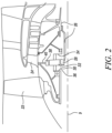
- FIG. 2 An exemplary arrangement for a geared fan gas turbine engine 10 is shown in Figure 2 .
- the low pressure turbine 19 (see Figure 1 ) drives the shaft 26, which is coupled to a sun wheel, or sun gear 28 of the epicyclic gearbox 30.
- a sun wheel, or sun gear 28 of the epicyclic gearbox 30 Radially outwardly of the sun gear 28 and intermeshing therewith is a plurality of planet gears 32 that are coupled together by a planet carrier 34.
- the planet carrier 34 constrains the planet gears 32 to process around the sun gear 28 in synchronicity whilst enabling each planet gear 32 to rotate about its own axis.
- the planet carrier 34 is coupled via linkages 36 to the fan 23 in order to drive its rotation about the rotational axis 9.
- an annulus or ring gear 38 Radially outwardly of the planet gears 32 and intermeshing therewith is an annulus or ring gear 38 that is coupled, via linkages 40, to a stationary supporting structure 24.
- low pressure turbine and “low pressure compressor” as used herein may be taken to mean the lowest pressure turbine stages and lowest pressure compressor stages (i.e., not including the fan 23) respectively and/or the turbine and compressor stages that are connected together by the shaft 26 with the lowest rotational speed in the engine 10 (i.e., not including the gearbox output shaft that drives the fan 23).
- the "low pressure turbine” and “low pressure compressor” referred to herein may alternatively be known as the "intermediate pressure turbine” and “intermediate pressure compressor”. Where such alternative nomenclature is used, the fan 23 may be referred to as a first, or lowest pressure, compression stage.
- the epicyclic gearbox 30 is shown by way of example in greater detail in Figure 3 .
- Each of the sun gear 28, the planet gears 32, and the ring gear 38 comprise teeth about their periphery to intermesh with the other gears. However, for clarity only exemplary portions of the teeth are illustrated in Figure 3 .
- Practical applications of a planetary epicyclic gearbox 30 generally comprise at least three planet gears 32.
- the epicyclic gearbox 30 illustrated by way of example in Figures 2 and 3 is of the planetary type, in that the planet carrier 34 is coupled to an output shaft via linkages 36, with the ring gear 38 fixed.
- the epicyclic gearbox 30 may be a star arrangement, in which the planet carrier 34 is held fixed, with the ring (or annulus) gear 38 allowed to rotate. In such an arrangement, the fan 23 is driven by the ring gear 38.
- the gearbox 30 may be a differential gearbox in which the ring gear 38 and the planet carrier 34 are both allowed to rotate.
- any suitable arrangement may be used for locating the gearbox 30 in the engine 10 and/or for connecting the gearbox 30 to the engine 10.
- the connections (such as, the linkages 36, 40 in the Figure 2 example) between the gearbox 30 and other parts of the engine 10 (such as the input shaft 26, the output shaft, and the fixed structure 24) may have any desired degree of stiffness or flexibility.
- any suitable arrangement of the bearings between rotating and stationary parts of the engine 10 may be used, and the invention is not limited to the exemplary arrangement of Figure 2 .
- the gearbox 30 has a star arrangement (described above)
- the skilled person would readily understand that the arrangement of output and support linkages and bearing locations would typically be different to that shown by way of example in Figure 2 .
- the present invention extends to a gas turbine engine having any arrangement of gearbox styles (for example, star or planetary), support structures, input and output shaft arrangements, and bearing locations.
- gearbox styles for example, star or planetary
- support structures for example, star or planetary
- input and output shaft arrangements for example, star or planetary
- the gearbox may drive additional and/or alternative components (e.g., the intermediate pressure compressor and/or a booster compressor).
- additional and/or alternative components e.g., the intermediate pressure compressor and/or a booster compressor.
- gas turbine engines to which the present invention may be applied may have alternative configurations.
- such engines may have an alternative number of compressors and/or turbines and/or an alternative number of interconnecting shafts.
- the gas turbine engine 10 shown in Figure 1 has a split flow nozzle 18, 20 meaning that the flow through the bypass duct 22 has its own nozzle 18 that is separate to and radially outside the core exhaust nozzle 20.
- this is not limiting, and any aspect of the present invention may also apply to engines in which the flow through the bypass duct 22 and the flow through the core 11 are mixed, or combined, before (or upstream of) a single nozzle, which may be referred to as a mixed flow nozzle.
- One or both nozzles may have a fixed or variable area.
- the described example relates to a turbofan engine, the invention may apply, for example, to any type of gas turbine engine, such as, an open rotor (in which the fan stage is not surrounded by a nacelle) or turboprop engine, for example.
- the gas turbine engine 10 may not comprise a gearbox 30.
- the geometry of the gas turbine engine 10, and components thereof, is defined by a conventional axis system, comprising an axial direction (which is aligned with the rotational axis 9), a radial direction (in the bottom-to-top direction in Figure 1 ), and a circumferential direction (perpendicular to the page in the Figure 1 view).
- the axial, radial, and circumferential directions are mutually perpendicular.
- present invention is equally applicable to aero gas turbine engines, marine gas turbine engines, and land-based gas turbine engines.
- Figure 4 shows a schematic perspective view of a casing assembly 100 for the gas turbine engine 10 (see Figure 1 ) having the rotational axis 9.
- the turbine 17, 19 (see Figure 1 ) for the gas turbine engine 10 includes the casing assembly 100.
- the compressor 14, 15 (see Figure 1 ) for the gas turbine engine 10 includes the casing assembly 100.
- a radial direction R is defined with respect to the rotational axis 9 of the gas turbine engine 10.
- terms that refer to a radial direction such as “radially outer”, “radially inner”, “radially extending”, “radially inwards”, “radially outwards", and “radially proximal", are with respect to the radial direction R.
- a circumferential direction C is defined with respect to the rotational axis 9.
- terms that refer to a circumferential direction such as “circumferential extends”, “circumferentially extending”, “circumferentially inclined”, and “circumferentially disposed between”, are with respect to the circumferential direction C.
- the casing assembly 100 includes a plurality of vane casing segments 102-1, 102-2, 102-3 circumferentially arranged about the rotational axis 9 and disposed adjacent to each other.
- the plurality of vane casing segments 102-1, 102-2, 102-3 includes at least three vane casing segments 102-1, 102-2, 102-3.
- the three vane casing segments 102-1, 102-2, 102-3 may allow easy assembly of the casing assembly 100 around a rotor (not shown) of the turbine 17, 19 or the compressor 14, 15.
- Each vane casing segment 102-1, 102-2, 102-3 extends about the rotational axis 9.
- Each vane casing segment 102-1, 102-2, 102-3 includes an arcuate member 104-1, 104-2, 104-3 extending circumferentially about the rotational axis 9.
- the arcuate member 104-1, 104-2, 104-3 of the at least one vane casing segment 102-1, 102-2, 102-3 has an angular extent E1-1, E1-2, E1-3 of at most 180 degrees about the rotational axis 9.
- the vane casing segment 102-1 includes a pair of split-line flanges 116-1, 116-2 circumferentially spaced apart from each other relative to the rotational axis 9.
- the vane casing segment 102-2 includes a pair of split-line flanges 116-3, 116-4 circumferentially spaced apart from each other relative to the rotational axis 9.
- the vane casing segment 102-3 includes a pair of split-line flanges 116-5, 116-6 circumferentially spaced apart from each other relative to the rotational axis 9.
- the designs of the split-line flanges 116-1, 116-2, 116-3, 116-4, 116-5, 116-6 may be similar to each other.
- the vane casing segments 102-1, 102-2, 102-3 may be similar to each other in design and dimensions.
- the vane casing segments 102-1, 102-2, 102-3 may be hereinafter collectively referred to as the vane casing segment 102.
- the term "vane casing segment 102" may be interchangeably used herein for each vane casing segment 102-1, 102-2, 102-3, without any limitations.
- the term “plurality of vane casing segments 102” may be interchangeably used herein for the plurality of vane casing segments 102-1, 102-2, 102-3, without any limitations.
- the arcuate member 104-1, 104-2, 104-3 may be hereinafter collectively referred to as the arcuate member 104.
- the term “arcuate member 104" may be interchangeably used herein for each arcuate member 104-1, 104-2, 104-3, without any limitations.
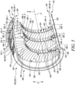
- FIG. 5 illustrates the single vane casing segment 102 of the casing assembly 100.
- each vane casing segment 102 includes the pair of split-line flanges 116-1, 116-2 circumferentially spaced apart from each other relative to the rotational axis 9.
- the split-line flange 116-1, 116-2 may be hereinafter collectively referred to as the split-line flange 116.
- the term “split-line flange 116" may be interchangeably used herein for each split-line flange 116-1, 116-2, without any limitations.
- the term “pair of split-line flanges 116" may be interchangeably used herein for the pair of split-line flange 116-1, 116-2, without any limitations.
- the arcuate member 104 includes a first axial end portion 106.
- the arcuate member 104 also includes a second axial end portion 108 axially spaced apart from the first axial end portion 106 relative to the rotational axis 9.
- the arcuate member 104 further includes a pair of circumferential ends 110, 112 circumferentially spaced apart from each other relative to the rotational axis 9 and extending between the first axial end portion 106 and the second axial end portion 108.
- the arcuate member 104 includes at least one row of casing apertures 114-1, 114-2, 114-3 circumferentially spaced apart from each other relative to the rotational axis 9.
- the at least one row of casing apertures 114-1, 114-2, 114-3 includes a plurality of rows of casing apertures 114-1, 114-2, 114-3. In the illustrated embodiment of Figure 5 , the at least one row of casing apertures 114-1, 114-2, 114-3 includes three rows of casing apertures 114-1, 114-2, 114-3.
- each split-line flange 116 from the pair of split-line flanges 116 may be integral with and radially extends from the arcuate member 104 relative to the rotational axis 9.
- Each split-line flange 116 may be disposed at a corresponding circumferential end 110, 112 from the pair of circumferential ends 110, 112 of the arcuate member 104 and may extend from the first axial end portion 106 of the arcuate member 104 to the second axial end portion 108 of the arcuate member 104.
- the split-line flange 116-1 is disposed at the circumferential end 110 and the split-line flange 116-2 is disposed at the circumferential end 112.
- Each split-line flange 116 includes a first axial flange end 118 disposed adjacent to the first axial end portion 106. Each split-line flange 116 also includes a second axial flange end 120 disposed adjacent to the second axial end portion 108. Each split-line flange 116 further includes a mating surface 122 extending between the first axial flange end 118 and the second axial flange end 120.
- the mating surface 122 includes a planar shape herein. Alternatively, the mating surface 122 may include any other shape, such as, a curved or helical shape, without any limitations.
- each split-line flange 116 includes an intersecting portion 136-1, 136-2, 136-3 disposed adjacent to at least one row of stator vanes 126-1, 126-2, 126-3.
- the split-line flange 116 includes three intersecting portions 136-1, 136-2, 136-3 disposed adjacent to the rows of stator vanes 126-1, 126-2, 126-3, respectively.
- each split-line flange 116 is fixedly coupled to an adjacent split line-flange 116-3 from the pair of split-line flanges 116-3, 116-4 (see Figure 4 ) of the adjacent vane casing segment 102 from the plurality of vane casing segments 102.
- the split-line flange 116-1 of the vane casing segment 102-1 is fixedly coupled to the adjacent split line-flange 116-3 of the vane casing segment 102-2.
- the at least one split-line flange 116 of the at least one vane casing segment 102 is directly and fixedly coupled to an adjacent split-line flange 116-3 of the adjacent vane casing segment 102.
- the split-line flange 116 may be fixedly connected to the split-line flange 116-3 via mechanical fasteners (not shown), such as, bolts, screws, pins, and the like.
- mechanical fasteners such as, bolts, screws, pins, and the like.
- the present invention is not limited by a technique of coupling the split-line flange 116 with the split-line flange 116-3.
- the split-line flanges 116, 116-3 may include features, such as, apertures (not shown), to receive the mechanical fasteners.
- the mating surface 122 of the at least one split-line flange 116 from the pair of split-line flanges 116 of the at least one vane casing segment 102 from the plurality of vane casing segments 102 at least partially engages with a mating surface 124 of the adjacent split-line flange 116-3 of the adjacent vane casing segment 102, such that the at least one row of stator vanes 126-1 of the at least one vane casing segment 102 at least partially forms a single circumferential row of stator vanes 128-1.
- the mating surface 124 includes a planar shape herein. Alternatively, the mating surface 124 may include any other shape, such as, a curved or helix shape, without any limitations.
- each split-line flange 116 is at least partially and circumferentially inclined to the rotational axis 9, such that the first axial flange end 118 is circumferentially offset from the second axial flange end 120.
- a circumferential offset C1 may be present between the first and second axial flange ends 118, 120.
- each vane casing segment 102 further includes the at least one row of stator vanes 126-1, 126-2, 126-3 circumferentially spaced apart from each other relative to the rotational axis 9 and fixedly coupled to the arcuate member 104. Details of the stator vane 126-1 will now be explained in reference to Figure 5 . However, the details provided below are equally applicable to the stator vanes 126-2, 126-3.
- Each stator vane 126-1 of the at least one row of stator vanes 126-1 includes an aerofoil 130 extending at least radially relative to the rotational axis 9 from a radially inner end 132 to a radially outer end 134.
- each stator vane 126-1 of the at least one row of stator vanes 126-1 includes an outer platform 137 disposed at the radially outer end 134 of the aerofoil 130.
- the outer platform 137 is at least partially received within a corresponding casing aperture 114-1 of the at least one row of casing apertures 114-1, 114-2, 114-3 of the arcuate member 104 and welded to the arcuate member 104.
- the at least one row of stator vanes 126-1 is circumferentially disposed between the pair of split-line flanges 116.
- the at least one row of stator vanes 126-1 includes a pair of end stator vanes 138-1, 138-2 disposed at corresponding opposite row ends 140, 142, such that each end stator vane 138-1 from the pair of end stator vanes 138-1, 138-2 is disposed adjacent to a corresponding split-line flange 116 from the pair of split-line flanges 116.
- the inclined split-flange 116 may eliminate a possibility of interference between the end stator vane 138-1 and the corresponding split-line flange 116.
- the intersecting portion 136-1 may mate with an intersecting portion 178 of the adjacent split-line flange 116-3.
- at least the intersecting portion 136-1 of each split-line flange 116 is circumferentially inclined relative to the rotational axis 9, such that the outer platform 137 of each end stator vane 138-1 is at least circumferentially spaced apart from the corresponding split-line flange 116 by a minimum circumferential clearance 144.
- the circumferentially inclined intersecting portion 136-1 of the at least one split-line flange 116 may ensure that the end stator vane 138-1 does not interfere with the corresponding split-line flange 116.
- the minimum circumferential clearance 144 may further provide sufficient access for welding of the outer platform 137 of the end stator vane 138-1 with the arcuate member 104 without any interference with the split-line flange 116.
- the entire split-line flange 116 is circumferentially inclined relative to the rotational axis 9, such that the outer platform 137 of each end stator vane 138-1 is at least circumferentially spaced apart from the corresponding split-line flange 116 by the minimum circumferential clearance 144.
- the minimum circumferential clearance 144 is from about 5 cm to about 10 cm. Such a range of the minimum circumferential clearance 144 may eliminate any interference between the end stator vane 138-1 and the corresponding split-line flange 116.
- the mating surface 122 of the split-line flange 116 may be circumferentially inclined relative to the rotational axis 9 by a circumferential angle A1.
- the circumferential angle A1 is from about 2 degrees to about 45 degrees. Further, the circumferential angle A1 may be from about 2 degrees to about 10 degrees, without any limitations. Such a range of the circumferential angle A1 may eliminate any interference between the end stator vane 138-1 and the at least one split-line flange 116.
- the circumferential angle A1 may be obtained based on the minimum circumferential clearance 144 to be maintained between the end stator vane 138-1 and the split-line flange 116, without any limitations.
- the casing assembly 100 further includes a shroud 146-1, 146-2, 146-3 radially spaced apart from the plurality of vane casing segments 102 relative to the rotational axis 9.
- the shroud 146-1, 146-2, 146-3 may include a plurality of shroud segments 148, 150, 152 (see Figure 4 ) circumferentially arranged about the rotational axis 9 and disposed adjacent to each other.
- each shroud segment 148, 150, 152 may include at least one row of shroud apertures 154 circumferentially spaced apart from each other relative to the rotational axis 9.
- each stator vane 126-1, 126-2, 126-3 of the at least one row of stator vanes 126-1 may be at least partially received within a corresponding shroud aperture 154 of the at least one row of shroud apertures 154 of a corresponding shroud segment 148, 150, 152 from the plurality of shroud segments 148, 150, 152.
- Each stator vane 126-1, 126-2, 126-3 may be therefore radially supported between the corresponding vane casing segment 102 and shroud segments 148, 150, 152.
- the casing assembly 100 further includes a potting material 158 disposed in each shroud aperture 154 of the at least one row of shroud apertures 154, such that the potting material 158 surrounds the radially inner end 132 of the aerofoil 130 received within the corresponding shroud aperture 154 and fixedly couples the radially inner end 132 to the corresponding shroud segment 148, 150, 152 (see Figure 4 ).
- the potting material 158 may provide retention and damping of the radially inner end 132 of the aerofoil 130. Further, the potting material may also provide a rubbing surface for seal fins.
- the potting material 158 may include silicone or sprayed ceramic material, without any limitations. The potting material 158 may be selected such that it exhibits adequate damping and may be able to withstand high temperatures.
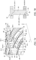
- each shroud segment 148 and the adjacent shroud segment 150 together form an interlocking arrangement 160, 162, 164 that connects each shroud segment 148 to the adjacent shroud segment 150.
- the interlocking arrangement 160 may connect the shroud segment 148 of the shroud 146-1 with the shroud segment 150 of the shroud 146-1.
- the interlocking arrangement 162 may connect the shroud segment 148 of the shroud 146-2 with the shroud segment 150 of the shroud 146-2.
- the interlocking arrangement 164 may connect the shroud segment 148 of the shroud 146-3 with the shroud segment 150 of the shroud 146-3.
- the interlocking arrangement 160, 162, 164 may eliminate any axial movement of the shroud segments 148, 150, 152 relative to the rotational axis 9. Further, the interlocking arrangement 160, 162, 164 does not include any additional components, such as, mechanical fasteners, thereby eliminating a cost and weight associated with such additional components. The interlocking arrangement 160, 162, 164 may provide improved vibration damping, seal clearance, and minimize leakage without incurring additional cost associated with fabricating and machining mating features.
- the interlocking arrangement 160, 162, 164 includes at least one of a Z-shaped arrangement, a V-shaped arrangement with axial end portions 166, 168, a V-shaped arrangement, and a zigzag arrangement (see Figures 8A to 8D , respectively).
- the interlocking arrangement 160, 162, 164 may include a tongue and groove arrangement, a dovetail arrangement, and the like. It should be noted that the interlocking arrangement 160, 162, 164 may include any design that may prevent the axial movement of the shroud segments 148, 150, 152 along the rotational axis 9. As shown in Figure 8A , the interlocking arrangement 160, 162, 164 connecting the shroud segments 148, 150 includes the Z-shaped arrangement.
- the interlocking arrangement 160, 162, 164 connecting the shroud segments 148, 150 includes the V-shaped arrangement with the axial end portions 166, 168.
- the interlocking arrangement 160, 162, 164 connecting the shroud segments 148, 150 includes the V-shaped arrangement.
- the interlocking arrangement 160, 162, 164 connecting the shroud segments 148, 150 includes the zigzag arrangement.
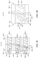
- Figure 9A is a schematic view depicting a split-line flange 916-1 associated with the vane casing segment 102 fixedly connected to a split-line flange 916-3 associated with the vane casing segment 102.
- the split-line flange 916-1 of the vane casing segment 102-1 is fixedly connected to the split-line flange 916-3 of the vane casing segment 102-2.
- the split-line flanges 916-1, 916-3 define corresponding mating surfaces 922, 924.
- Each of the mating surfaces 922, 924 include a planar shape herein. Alternatively, the mating surfaces 922, 924 may include any other shape, such as, a curved or helix shape, without any limitations.
- the split-line flange 916-1 includes an intersecting portion 936-1 that may mate with an intersecting portion 978-1 of the adjacent split-line flange 916-3.
- at least the intersecting portion 936-1 of the at least one split-line flange 916-1 of each vane casing segment 102 is circumferentially inclined relative to the rotational axis 9 by a circumferential angle A2.
- the outer platform 137 of the end stator vane 138-1 disposed adjacent to the at least one split-line flange 916-1 defines a chordal axis B1 extending between opposing axial ends 970, 972 of the outer platform 137.
- the chordal axis B1 is circumferentially inclined relative to the rotational axis 9 by the circumferential angle A2 of the at least one split-line flange 916-1.
- the circumferential angle A2 is from about 2 degrees to about 45 degrees. Further, the circumferential angle A2 may be from about 2 degrees to about 10 degrees, without any limitations. Such a range of the circumferential angle A2 may eliminate any interference between the end stator vane 138-1 and the at least one split-line flange 916-1.
- the circumferentially inclined intersecting portion 936-1 of the split-line flange 916-1 may ensure that the end stator vane 138-1 of the vane casing segment 102 may be disposed at a minimum circumferential clearance 944-1 from the split-line flange 916-1. Further, the circumferentially inclined intersecting portion 936-1 may ensure that the end stator vane 138-1 does not interfere with the split-line flange 916-1. As illustrated herein, the split-line flange 916-1 may also include a pair of axial portions 974-1 that extend parallel to the rotational axis 9. The intersecting portion 936-1 extends between the pair of axial portions 974-1.
- the at least one row of stator vanes 126-1, 126-2, 126-3 further includes the plurality of rows of stator vanes 126-1, 126-2, 126-3 axially spaced apart from each other relative to the rotational axis 9 and fixedly coupled to the arcuate member 104.
- the at least one row of casing apertures 114-1, 114-2, 114-3 may further include the plurality of rows of casing apertures 114-1, 114-2, 114-3 corresponding to the plurality of rows of stator vanes 126-1, 126-2, 126-3.
- each split-line flange 916-2 further includes a plurality of intersecting portions 936-2, 936-3, 936-4 disposed adjacent to the corresponding row of stator vanes 126-1, 126-2, 126-3 from the plurality of rows of stator vanes 126-1, 126-2, 126-3.
- the intersecting portion 936-2 of the split-line flange 916-2 may mate with an intersecting portion 978-2 of an adjacent split-line flange 916-5.
- the intersecting portion 936-3 of the split-line flange 916-2 may mate with an intersecting portion 978-3 of the adjacent split-line flange 916-5.
- the intersecting portion 936-4 of the split-line flange 916-2 mates with an intersecting portion 978-4 of the adjacent split-line flange 916-5.
- At least one intersecting portion 936-2, 936-3, 936-4 from the plurality of intersecting portions 936-2, 936-3, 936-4 may be circumferentially inclined relative to the rotational axis 9.
- the at least one circumferentially inclined intersecting portion 936-2, 936-3, 936-4 may ensure that the end stator vane 138-1 of the vane casing segment 102 does not interfere with the corresponding split-line flange 916-2.
- each intersecting portion 936-2, 936-3, 936-4 from the plurality of intersecting portions 936-2, 936-3, 936-4 is circumferentially inclined relative to the rotational axis 9 by a corresponding circumferential angle A3.
- a value of the circumferential angles A3 of each intersecting portion 936-2, 936-3, 936-4 may be the same.
- the circumferential angle A3 is from about 2 degrees to about 45 degrees. Further, the circumferential angle A3 may be from about 2 degrees to about 10 degrees, without any limitations. Such a range of the circumferential angle A3 may eliminate any interference between the end stator vane 138-1 and the corresponding split-line flange 916-2, 916-3, 916-4.
- the intersecting portions 936-2, 936-3, 936-4 are parallel to each other.
- the split-line flange 916-2 also may also include corresponding axial portions 974-2 that extend parallel to the rotational axis 9.
- One of the axial portions 974-2 may be axially disposed between the intersecting portions 936-2 and 936-3 relative to the rotational axis 9. Further, one of the axial portions 974-2 may be axially disposed between the intersecting portions 936-3 and 936-4 relative to the rotational axis 9. At least a part of the split-line flange 916-2 may therefore include alternating axially parallel portions and circumferentially inclined portions.
- Figure 9C is a schematic view depicting a split-line flange 916-4 associated with the vane casing segment 102 fixedly connected to a split-line flange 916-7 associated with the vane casing segment 102.
- the split-line flange 916-4 of the vane casing segment 102-1 is fixedly connected to the split-line flange 916-7 of the vane casing segment 102-2.
- the split-line flange 916-4 includes three intersecting portions 936-5, 936-6, 936-7. Further, the intersecting portion 936-5 of the split-line flange 916-4 may mate with a corresponding intersecting portion 978-5 of the split-line flange 916-7.
- intersecting portion 936-6 of the split-line flange 916-4 may mate with a corresponding intersecting portion 978-6 of the split-line flange 916-7.
- intersecting portion 936-7 of the split-line flange 916-4 may mate with a corresponding intersecting portion 978-7 of the split-line flange 916-7.
- Each of the three intersecting portions 936-5, 936-6, 936-7 of the split-line flange 916-4 are disposed adjacent to a corresponding row of stator vanes 126-1, 126-2, 126-3.
- the intersecting portions 936-5, 936-6 may be circumferentially inclined relative to the rotational axis 9 by a corresponding circumferential angle A4, A5.
- the corresponding circumferential angles A4, A5 of at least two intersection portions 936-5, 936-6 from the plurality of intersection portions 936-5, 936-6 are different from each other.
- a value of the circumferential angle A4 of the intersecting portion 936-5 may be different from a value of the circumferential angle A5 of the intersecting portion 936-6.
- the different values of the circumferential angles A4, A5 may be based on different designs of the at least two rows of stator vanes 126-1, 126-2 corresponding to the at least two intersection portions 936-5, 936-6.
- the circumferential angle A4, A5 is from about 2 degrees to about 45 degrees. Further, the circumferential angle A4, A5 may be from about 2 degrees to about 10 degrees, without any limitations. Such a range of the circumferential angle A4, A5 may eliminate any interference between the end stator vane 138-1 and the corresponding split-line flange 916-5, 916-6. Moreover, at least one of the plurality of intersecting portions 936-7 extends parallel to the rotational axis 9. In such an example, a circumferential inclination of the at least one of the plurality of intersecting portions 936-7 may not be required due to a design of the corresponding row of stator vanes 126-3. As illustrated herein, the split-line flange 916-5 may also include corresponding axial portions 974-3 that extend parallel to the rotational axis 9.
- Figure 9D is a schematic view depicting a split-line flange 916-6 associated with the vane casing segment 102 fixedly connected to a split-line flange 916-9 associated with the vane casing segment 102.
- the split-line flange 916-6 of the vane casing segment 102-1 is fixedly connected to the split-line flange 916-9 of the vane casing segment 102-2.
- the split-line flanges 916-6, 916-9 define corresponding mating surfaces 922-1, 924-1.
- each of the mating surfaces 922-1, 924-1 include a curved shape.
- the split-line flange 916-6 includes a convex shape and the split-line flange 916-9 includes a concave shape.
- the mating surfaces 922-1, 924-1 may include any other shape, without any limitations.
- the casing assembly 100 may also include a vane plate unit 1000-1, 1000-2, 1000-3.
- the plurality of vane casing segments 102-1, 102-2, 102-3 includes at least three vane casing segments 102-1, 102-2, 102-3, such that the angular extent E1-1, E1-2, E1-3 of the arcuate member 104-1, 104-2, 104-3 of each of the at least three vane casing segments 102-1, 102-2, 102-3 is less than 180 degrees about the rotational axis 9.
- the at least one vane plate unit 1000-1, 1000-2, 1000-3 includes at least three vane plate units 1000-1, 1000-2, 1000-3, such that each of the at least three vane plate units 1000-1, 1000-2, 1000-3 is at least partially and circumferentially disposed between corresponding adjacent vane casing segments 102-1, 102-2, 102-3 of the at least three vane casing segments 102-1, 102-2, 102-3.
- the vane pate unit 1000-1 is circumferentially disposed between the vane casing segments 102-1, 102-2.
- the vane pate unit 1000-2 is circumferentially disposed between the vane casing segments 102-2, 102-3.
- the vane pate unit 1000-3 is circumferentially disposed between the vane casing segments 102-1, 102-3.
- Figure 11 illustrates the vane plate unit 1000-1 disposed between the vane casing segments 102-1, 102-2.
- the vane plate unit 1000-1 will now be described in detail. However, details provided below may be equally applicable to the vane plate units 1000-2, 1000-3 shown in Figure 10 , without any limitations.
- the casing assembly 100 further includes the at least one vane plate unit 1000-1 at least partially and circumferentially disposed between at least one split-line flange 116 from the pair of split-line flanges 116 of at least one vane casing segment 102-1 from the plurality of vane casing segments 102-1, 102-2, 102-3 (see Figure 10 ) and the adjacent split line flange 116-3 of the adjacent vane casing segment 102-2.
- the vane plate unit 1000-1 may include a vane plate 1002 including a first mating surface 1004 at least partially engaging with the mating surface 122 of the at least one split-line flange 116 of the at least one vane casing segment 102-1. Further, the split-line flange 116 may be fixedly connected to the vane plate 1002 via mechanical fasteners (not shown), such as, bolts, screws, pins, and the like. Accordingly, the vane plate 1002 may include features, such as, apertures (not shown), to receive the mechanical fasteners. It should be noted that the present invention is not limited by a technique of coupling the split-line flange 116 with the vane plate 1002.
- the vane plate 1002 may also include an opposing second mating surface 1006 at least partially engaging with the mating surface 124 of the adjacent split line flange 116-3 of the adjacent vane casing segment 102-2. Further, the split-line flange 116-3 may be fixedly connected to the vane plate 1002 via mechanical fasteners, such as, bolts, screws, pins, and the like. It should be noted that the present invention is not limited by a technique of coupling the split-line flange 116-3 with the vane plate 1002.
- the vane plate 1002 described herein may be used when a clearance between the end stator vane 138-1 of the vane casing segment 102-1 and an end stator vane 138-2 of the vane casing segment 102-2 may be such that it may be challenging to accommodate the split-line flange 116 of the vane casing segment 102-1 and the split-line flange 116-3 of the vane casing segment 102-2.
- the vane plate 1002 may be fixedly coupled to each of the at least one split-line flange 116 and the adjacent split-line flange 116-3, such that the at least one split-line flange 116 may be fixedly coupled to the adjacent split-line flange 116-3 via the vane plate 1002.
- the vane plate 1002 may be at least partially and circumferentially inclined relative to the rotational axis 9. In the illustrated embodiment of Figure 11 , the entire vane plate 1002 is circumferentially inclined relative to the rotational axis 9. Further, the vane plate 1002 may be circumferentially inclined relative to the rotational axis 9 by a circumferential angle A6.
- the circumferential angle A6 may be from about 2 degrees to about 45 degrees. Further, the circumferential angle A6 may be from about 2 degrees to about 10 degrees, without any limitations.
- the vane plate 1002 has an angular extent E2 about the rotational axis 9.
- the arcuate member 104-1, 104-2, 104-3 of each vane casing segment 102-1, 102-2, 102-3 may have the angular extent E1-1, E1-2, E1-3 about the rotational axis 9.
- the angular extent A2 of each vane casing segment 102-1, 102-2, 102-3 may be greater than the angular extent E2 of the vane plate 1002 by at least a factor of 20.
- the angular extent E2 of the vane plate 1002 may be governed by a desired clearance between the end stator vanes 138-1, 138-2 of the adjacent vane casing segments 102-1, 102-2.
- the vane plate unit 1000-1 includes at least one plate stator vane 1008-1, 1008-2, 1008-3 fixedly coupled to and extending at least radially from the vane plate 1002.
- each vane plate unit 1000-1 may include the plurality of plate stator vanes 1008-1, 1008-2, 1008-3.
- the plate stator vane 1008-1, 1008-2, 1008-3 may be equidistant from each other relative to the rotational axis 9.
- the plate stator vane 1008-1, 1008-2, 1008-3 may be unevenly spaced along the rotational axis 9.
- the vane plate 1002 further includes at least one plate aperture 1014 (shown in Figure 11 ).
- the at least one plate stator vane 1008-1, 1008-2, 1008-3 may include an aerofoil 1016 extending at least radially relative to the rotational axis 9 from a radially inner end 1018 to a radially outer end 1020, and an outer platform 1022 (shown in Figure 11 ) disposed at the radially outer end 1020 of the aerofoil 1016.
- the outer platform 1022 may be at least partially received within the at least one plate aperture 1014 of the vane plate 1002.
- the plate stator vanes 1008-1, 1008-2, 1008-3 may either be integrally formed with the vane plate 1002 or the plate stator vanes 1008-1, 1008-2, 1008-3 may be coupled to the vane plate 1002 by welding, thereby eliminating usage of additional components, such as, mechanical fasteners. Accordingly, the vane plate 1002 may not increase an overall weight and cost associated with the casing assembly 100.
- the outer platform 1022 of the at least one plate stator vane 1008-1 may define a chordal axis B2 extending between opposing axial ends 1026, 1030 of the outer platform 1022.
- the chordal axis B2 may be circumferentially inclined relative to the rotational axis 9 by the same circumferential angle A6.
- the at least one plate stator vane 1008-1 is circumferentially disposed between the proximal end stator vane 138-1 of the at least one vane casing segment 102-1 and the proximal end stator vane 138-2 of the adjacent vane casing segment 102-2, such that the at least one row of stator vanes 126-1 of the at least one vane casing segment 102-1, the at least one plate stator vane 1008-1 of the vane plate unit 1000-1, and at least one row of stator vanes 126-4 of the adjacent vane casing segment 102-2 together at least partially form a single circumferential row of stator vanes 1028.
- the vane plate 1002 may further include an intersecting portion 1010 axially intersecting the single circumferential row of stator vanes 1028. Further, at least the intersecting portion 1010 of the vane plate 1002, at least the intersecting portion 136-1 of the at least one split-line flange 116 of the at least one vane casing segment 102-1, and at least the intersecting portion 178 of the adjacent split-line flange 116-3 of the adjacent vane casing segment 102-2 may be circumferentially inclined relative to the rotational axis 9 by the same circumferential angle A6.
- the circumferentially inclined intersecting portion 1010 of the vane plate 1002 may ensure that the plate stator vane 1008-1 is equidistantly disposed between each of the end stator vanes 138-1, 138-2 of the adjacent vane casing segments 102-1, 102-2.
- the vane plate unit 1200 includes a vane plate 1202 and a plate stator vane 1208.
- the at least one plate stator vane 1208 may be circumferentially disposed between the proximal end stator vane 138-1 of the at least one vane casing segment 102-1 and the proximal end stator vane 138-2 of the adjacent vane casing segment 102-2, such that the at least one row of stator vanes 126-1 of the at least one vane casing segment 102-1, the at least one plate stator vane 1208 of the vane plate unit 1202, and at least one row of stator vanes 126-4 of the adjacent vane casing segment 102-2 together at least partially form a single circumferential row of stator vanes 1228.
- the vane plate 1202 further may include an intersecting portion 1210 axially intersecting the single circumferential row of stator vanes 1228. In the illustrated embodiment of Figure 12B , only the intersecting portion 1210 of the vane plate 1202 is circumferentially inclined relative to the rotational axis 9 by a circumferential angle A7.
- At least the intersecting portion 1210 of the vane plate 1202, at least the intersecting portion 136-1 of the at least one split-line flange 116 of the at least one vane casing segment 102-1, and at least the intersecting portion 178 of the adjacent split-line flange 116-3 of the adjacent vane casing segment 102-2 may be circumferentially inclined relative to the rotational axis 9 by the same circumferential angle A7.
- the circumferential angle A7 is from about 2 degrees to about 45 degrees. Further, the circumferential angle A7 may be from about 2 degrees to about 10 degrees, without any limitations.
- the circumferentially inclined intersecting portion 1210 of the vane plate 1202 may ensure that the plate stator vane 1208 is equidistantly disposed between each of the end stator vanes 138-1, 138-2 of the adjacent vane casing segments 102-1, 102-2.
- the vane plate unit 1200 may include multiple intersecting portions (not shown) that may be similar to the intersecting portion 1210.
- each of the multiple intersecting portions of the vane plate unit 1200 may be circumferentially inclined relative to the rotational axis 9 by a circumferential angle (not shown).
- the circumferential angles of at least two of the multiple intersecting portions of the vane plate unit 1200 may be different from each other.
- the circumferential angles of at least two of the multiple intersecting portions may be same.
- at least one of the multiple intersecting portions of the vane plate unit 1200 may extend parallel to the rotational axis 9.
- the casing assembly 100 of the present invention may be robust in design and may be convenient to assemble around the rotor of the turbine 17, 19 or the compressor 14, 15, without compromising with a design of the rotor. Further, as the rows of stator vanes 126-1, 126-2, 126-3, 126-4, are coupled to the arcuate member 104-1, 104-2 by welding, the casing assembly 100 may have a lower weight as the casing assembly 100 may not require mechanical fasteners, such as, bolts for coupling the rows of stator vanes 126-1, 126-2, 126-3, 126-4 with the arcuate member 104-1, 104-2. Moreover, the casing assembly 100 may be cost effective due to usage of lower volume of materials for manufacturing of the casing assembly 100.
Landscapes
- Engineering & Computer Science (AREA)
- Mechanical Engineering (AREA)
- General Engineering & Computer Science (AREA)
- Structures Of Non-Positive Displacement Pumps (AREA)
Abstract
Description
- The present invention generally relates to gas turbine engines, more particularly, to a casing assembly for a turbine or a compressor of a gas turbine engine.
- A gas turbine engine generally includes a turbine and a compressor. Each of the turbine and the compressor includes a casing, and a stator and a rotor disposed within the casing. The stator may include a number of vanes that are coupled to the casing. Further, in some examples, the casing may be split axially into two halves along a horizontal plane. The two halves may be bolted together via mating flanges. Conventionally, the vanes may be connected to the casing using mechanical fasteners, such as, bolts. Such mechanical fasteners may increase a number of parts associated with the gas turbine engine, a cost associated with manufacturing of the gas turbine engine, and an overall weight of the gas turbine engine. Further, conventional vane and casing assemblies may not have a robust design. Moreover, it may be challenging to assemble the vane and casing assembly around the rotor, which may increase a time and cost associated with an assembling of the gas turbine engine.
- Further, the casing may include one or more shrouds that may be connected with the vanes of the stator. Such shrouds may include a number of shroud segments. Conventionally, adjacent shroud segments may be connected to each other by various joining techniques, such as, welding or using mechanical fasteners. However, such joining techniques may require multiple machining and/or fabrication operations which may add to a manufacturing cost and may also introduce a risk of damage to other surrounding components, for example, if the mechanical fasteners get loose and escape into a main gas flow path. Further, usage of mechanical fasteners to join adjacent shroud segments may increase the weight and cost associated with the gas turbine engine.
- In a first aspect, there is provided a casing assembly according to claim 1.
- The casing assembly of the present invention may be robust in design. The casing assembly may also be convenient to assemble around a rotor associated with a turbine or a compressor of the gas turbine engine, without compromising with a design of the rotor. Further, as the stator vanes are coupled to the arcuate member by welding, the casing assembly may have a lower weight as the casing assembly may not require mechanical fasteners, such as bolts, for coupling of the stator vanes with the arcuate member. Furthermore, the casing assembly may be cost efficient due to usage of lower volume of materials for manufacturing of the casing assembly. Moreover, the minimum circumferential clearance between the end stator vane and the split-line flange may eliminate an interference between the end stator vane and the corresponding split-line flange. The minimum circumferential clearance may further provide sufficient access for welding of the outer platform of the end stator vane with the arcuate member without any interference with the split-line flange.
- In some embodiments, the casing assembly further includes at least one vane plate unit at least partially and circumferentially disposed between at least one split-line flange from the pair of split-line flanges of at least one vane casing segment from the plurality of vane casing segments and the adjacent split-line flange of the adjacent vane casing segment. The vane plate described herein may be used when a clearance between the end stator vanes of adjacent vane casing segments is such that it may be challenging to accommodate the split-line flanges therebetween.
- The vane plate unit includes a vane plate including a first mating surface at least partially engaging with the mating surface of the at least one split-line flange of the at least one vane casing segment and an opposing second mating surface at least partially engaging with the mating surface of the adjacent split-line flange of the adjacent vane casing segment. The vane plate is fixedly coupled to each of the at least one split-line flange and the adjacent split-line flange, such that the at least one split-line flange is fixedly coupled to the adjacent split-line flange via the vane plate. The vane plate is at least partially and circumferentially inclined relative to the rotational axis. The vane plate further includes at least one plate stator vane fixedly coupled to and extending at least radially from the vane plate. The at least one plate stator vane is circumferentially disposed between the proximal end stator vane of the at least one vane casing segment and the proximal end stator vane of the adjacent vane casing segment, such that the at least one row of stator vanes of the at least one vane casing segment, the at least one plate stator vane of the vane plate unit, and the at least one row of stator vanes of the adjacent vane casing segment together at least partially form a single circumferential row of stator vanes. The vane plate may be disposed such that a desired clearance may be maintained between the plate stator vane and the end stator vane of each of the adjacent vane casing segments.
- In some embodiments, the vane plate has an angular extent about the rotational axis. The arcuate member of each vane casing segment has an angular extent about the rotational axis. The angular extent of each vane casing segment is greater than the angular extent of the vane plate by at least a factor of 20. The angular extent of the vane plate may be governed by a desired clearance between the end stator vanes of adjacent vane casing segments.
- In some embodiments, the vane plate further includes an intersecting portion axially intersecting the single circumferential row of stator vanes. At least the intersecting portion of the vane plate, at least the intersecting portion of the at least one split-line flange of the at least one vane casing segment, and at least the intersecting portion of the adjacent split-line flange of the adjacent vane casing segment are circumferentially inclined relative to the rotational axis by a same circumferential angle. The circumferentially inclined intersecting portion of the vane plate may ensure that the plate stator vane is equidistantly disposed between each of the adjacent vane casing segments.
- In some embodiments, the vane plate further includes at least one plate aperture. The at least one plate stator vane includes an aerofoil extending at least radially relative to the rotational axis from a radially inner end to a radially outer end, and an outer platform disposed at the radially outer end of the aerofoil. The outer platform is at least partially received within the at least one plate aperture of the vane plate. The outer platform of the at least one plate stator vane defines a chordal axis extending between opposing axial ends of the outer platform. The chordal axis is circumferentially inclined relative to the rotational axis by the same circumferential angle. Further, the plate stator vane may either be integrally formed with the vane plate or the plate stator vane may be coupled to the vane plate by welding, thereby eliminating usage of additional components, such as, mechanical fasteners. Thus, additional weight and cost associated with such additional components may be eliminated.
- In some embodiments, the plurality of vane casing segments includes at least three vane casing segments, such that the angular extent of the arcuate member of each of the at least three vane casing segments is less than 180 degrees about the rotational axis. The at least one vane plate unit includes at least three vane plate units, such that each of the at least three vane plate units is at least partially and circumferentially disposed between corresponding adjacent vane casing segments of the at least three vane casing segments. The three vane casing segments may allow easy assembly of the casing assembly around the rotor.
- In some embodiments, the mating surface of at least one split-line flange from the pair of split-line flanges of at least one vane casing segment from the plurality of vane casing segments at least partially engages with the mating surface of the adjacent split-line flange of the adjacent vane casing segment, such that the at least one row of stator vanes of the at least one vane casing segment at least partially forms a single circumferential row of stator vanes, and wherein at least one split-line flange of the at least one vane casing segment is directly and fixedly coupled to the adjacent split-line flange of the adjacent vane casing segment.
- In some embodiments, the arcuate member of the at least one vane casing segment has an angular extent of at most 180 degrees about the rotational axis. The arcuate member may allow easy assembly of the casing assembly around the rotor.
- In some embodiments, the minimum circumferential clearance is from about 5 cm to about 10 cm. Such a range of the minimum circumferential clearance may eliminate any interference between the end stator vane and the corresponding split-line flange.
- In some embodiments, at least the intersecting portion of at least one split-line flange of each vane casing segment is circumferentially inclined relative to the rotational axis by a circumferential angle. The outer platform of the end stator vane disposed adjacent to the at least one split-line flange defines a chordal axis extending between opposing axial ends of the outer platform. The chordal axis is circumferentially inclined relative to the rotational axis by the circumferential angle of the at least one split-line flange. The circumferentially inclined intersecting portion of the at least one split-line flange may ensure that the end stator vane of the vane casing segment is disposed at the minimum circumferential clearance from the at least one split-line flange. Further, the circumferentially inclined intersecting portion of the at least one split-line flange may ensure that the end stator vane does not interfere with the at least one split-line flange.
- In some embodiments, the circumferential angle is from about 2 degrees to about 45 degrees. Such a range of the circumferential angle may eliminate any interference between the end stator vane and the at least one split-line flange.
- In some embodiments, the at least one row of stator vanes further includes a plurality of rows of stator vanes axially spaced apart from each other relative to the rotational axis and fixedly coupled to the arcuate member. The at least one row of casing apertures further includes a plurality of rows of casing apertures corresponding to the plurality of rows of stator vanes. Each split-line flange further includes a plurality of intersecting portions disposed adjacent to a corresponding row of stator vanes from the plurality of rows of stator vanes. Further, at least one intersecting portion from the plurality of intersecting portions is circumferentially inclined relative to the rotational axis. The at least one circumferentially inclined intersecting portion may ensure that the end stator vane of the vane casing segment does not interfere with the corresponding split-line flange.
- In some embodiments, each intersecting portion from the plurality of intersecting portions is circumferentially inclined relative to the rotational axis by a corresponding circumferential angle.
- In some embodiments, the corresponding circumferential angles of at least two intersection portions from the plurality of intersection portions are different from each other. The different values of the circumferential angles may be based on different designs of the at least two rows of stator vanes corresponding to the at least two intersection portions.
- In some embodiments, at least one of the plurality of intersecting portions extends parallel to the rotational axis. In such a case, a circumferential inclination of the at least one of the plurality of intersecting portions may not be required due to a design of the corresponding row of stator vanes.
- In some embodiments, the casing assembly further includes a shroud radially spaced apart from the plurality of vane casing segments relative to the rotational axis. The shroud includes a plurality of shroud segments circumferentially arranged about the rotational axis and disposed adjacent to each other. Each shroud segment includes at least one row of shroud apertures circumferentially spaced apart from each other relative to the rotational axis. The radially inner end of the aerofoil of each stator vane of the at least one row of stator vanes is at least partially received within a corresponding shroud aperture of the at least one row of shroud apertures of a corresponding shroud segment from the plurality of shroud segments. Each stator vane may be therefore radially supported between the corresponding vane casing segment and shroud segments.
- In some embodiments, each shroud segment and an adjacent shroud segment together form an interlocking arrangement that connects each shroud segment to the adjacent shroud segment. Such an interlocking arrangement may eliminate any axial movement of the shroud segments relative to the rotational axis. Further, the interlocking arrangement does not include any additional components, such as, mechanical fasteners, thereby eliminating a cost and weight associated with such additional components. The interlocking arrangement may provide improved vibration damping, seal clearance, and minimize leakage without incurring additional cost associated with fabricating and machining mating features.
- In some embodiments, the interlocking arrangement includes at least one of a Z-shaped arrangement, a V-shaped arrangement with axial end portions, a V-shaped arrangement, and a zigzag arrangement. Such interlocking arrangements may eliminate any axial movement of the shroud segments relative to the rotational axis.
- In some embodiments, the casing assembly further includes a potting material disposed in each shroud aperture of the at least one row of shroud apertures, such that the potting material surrounds the radially inner end of the aerofoil received within the corresponding shroud aperture and fixedly couples the radially inner end to the corresponding shroud segment. The potting material may provide retention and damping of the radially inner end of the aerofoil. Further, the potting material may also provide a rubbing surface for seal fins.
- In a second aspect, there is provided a turbine or a compressor for a gas turbine engine, the turbine or the compressor includes the casing assembly of the first aspect.
- In a third aspect, there is provided a gas turbine engine that includes the casing assembly of the first aspect.
- As noted elsewhere herein, the present invention may relate to gas turbine engines. Such gas turbine engines may comprise an engine core comprising a turbine, a combustor, a compressor, and a core shaft connecting the turbine to the compressor. Such gas turbine engines may comprise a fan (having fan blades) located upstream of the engine core.
- Arrangements of the present invention may be particularly, although not exclusively, beneficial for fans that are driven via a gearbox. Accordingly, the gas turbine engine may comprise a gearbox that receives an input from the core shaft and outputs drive to the fan so as to drive the fan at a lower rotational speed than the core shaft. The input to the gearbox may be directly from the core shaft, or indirectly from the core shaft, for example, via a spur shaft and/or gear. The core shaft may rigidly connect the turbine and the compressor, such that the turbine and the compressor rotate at the same speed (with the fan rotating at a lower speed).
- The gas turbine engine as described and/or claimed herein may have any suitable general architecture. For example, the gas turbine engine may have any desired number of shafts that connect turbines and compressors, for example, one, two, or three shafts. Purely by way of example, the turbine connected to the core shaft may be a first turbine, the compressor connected to the core shaft may be a first compressor, and the core shaft may be a first core shaft. The engine core may further comprise a second turbine, a second compressor, and a second core shaft connecting the second turbine to the second compressor. The second turbine, the second compressor, and the second core shaft may be arranged to rotate at a higher rotational speed than the first core shaft.
- In such an arrangement, the second compressor may be positioned axially downstream of the first compressor. The second compressor may be arranged to receive (for example directly receive, for example via a generally annular duct) flow from the first compressor.
- The gearbox may be arranged to be driven by the core shaft that is configured to rotate (for example in use) at the lowest rotational speed (for example the first core shaft in the example above). For example, the gearbox may be arranged to be driven only by the core shaft that is configured to rotate (for example in use) at the lowest rotational speed (for example only be the first core shaft, and not the second core shaft, in the example above). Alternatively, the gearbox may be arranged to be driven by any one or more shafts, for example, the first and/or second shafts in the example above.
- The gearbox may be a reduction gearbox (in that the output to the fan is a lower rotational rate than the input from the core shaft). Any type of gearbox may be used. For example, the gearbox may be a "planetary" or "star" gearbox, as described in more detail elsewhere herein. The gearbox may have any desired reduction ratio (defined as the rotational speed of the input shaft divided by the rotational speed of the output shaft), for example greater than 2.5, for example in the range of from 3 to 4.2, or 3.2 to 3.8, for example on the order of or at least 3, 3.1, 3.2, 3.3, 3.4, 3.5, 3.6, 3.7, 3.8, 3.9, 4, 4.1 or 4.2. The gear ratio may be, for example, between any two of the values in the previous sentence. Purely by way of example, the gearbox may be a "star" gearbox having a ratio in the range of from 3.1 or 3.2 to 3.8. In some arrangements, the gear ratio may be outside these ranges.
- In any gas turbine engine as described and/or claimed herein, a combustor may be provided axially downstream of the fan and compressor(s). For example, the combustor may be directly downstream of (for example at the exit of) the second compressor, where a second compressor is provided. By way of further example, the flow at the exit to the combustor may be provided to the inlet of the second turbine, where a second turbine is provided. The combustor may be provided upstream of the turbine(s).
- The or each compressor (for example the first compressor and the second compressor as described above) may comprise any number of stages, for example multiple stages. Each stage may comprise a row of rotor blades and a row of stator vanes, which may be variable stator vanes (in that their angle of incidence may be variable). The row of rotor blades and the row of stator vanes may be axially offset from each other.
- The or each turbine (for example the first turbine and the second turbine as described above) may comprise any number of stages, for example, multiple stages. Each stage may comprise a row of rotor blades and a row of stator vanes. The row of rotor blades and the row of stator vanes may be axially offset from each other.
- A fan blade and/or aerofoil portion of a fan blade described and/or claimed herein may be manufactured from any suitable material or combination of materials. For example, at least a part of the fan blade and/or aerofoil may be manufactured at least in part from a composite, for example, a metal matrix composite and/or an organic matrix composite, such as carbon fibre. By way of further example, at least a part of the fan blade and/or aerofoil may be manufactured at least in part from a metal, such as, a titanium-based metal or an aluminium based material (such as an aluminium-lithium alloy) or a steel-based material. The fan blade may comprise at least two regions manufactured using different materials. For example, the fan blade may have a protective leading edge, which may be manufactured using a material that is better able to resist impact (for example from birds, ice, or other material) than the rest of the blade. Such a leading edge may, for example, be manufactured using titanium or a titanium-based alloy. Thus, purely by way of example, the fan blade may have a carbon-fibre or aluminium based body (such as an aluminium lithium alloy) with a titanium leading edge.
- A fan as described and/or claimed herein may comprise a central portion, from which the fan blades may extend, for example, in a radial direction. The fan blades may be attached to the central portion in any desired manner. For example, each fan blade may comprise a fixture which may engage a corresponding slot in the hub (or disc). Purely by way of example, such a fixture may be in the form of a dovetail that may slot into and/or engage a corresponding slot in the hub/disc in order to fix the fan blade to the hub/disc. By way of further example, the fan blades maybe formed integrally with a central portion. Such an arrangement may be referred to as a bladed disc or a bladed ring. Any suitable method may be used to manufacture such a bladed disc or bladed ring. For example, at least a part of the fan blades may be machined from a block and/or at least part of the fan blades may be attached to the hub/disc by welding, such as linear friction welding.
- The gas turbine engines described and/or claimed herein may or may not be provided with a variable area nozzle (VAN). Such a variable area nozzle may allow the exit area of the bypass duct to be varied in use. The general principles of the present invention may apply to engines with or without a VAN.
- The fan of a gas turbine as described and/or claimed herein may have any desired number of fan blades, for example, 14, 16, 18, 20, 22, 24, or 26 fan blades.
- The skilled person will appreciate that except where mutually exclusive, a feature or parameter described in relation to any one of the above aspects may be applied to any other aspect. Furthermore, except where mutually exclusive, any feature or parameter described herein may be applied to any aspect and/or combined with any other feature or parameter described herein.
- Embodiments will now be described by way of example only, with reference to the Figures, in which:
-
Figure 1 is a sectional side view of a gas turbine engine according to an embodiment of the present invention; -
Figure 2 is a close-up sectional side view of an upstream portion of the gas turbine engine ofFigure 1 according to an embodiment of the present invention; -
Figure 3 is a partially cut-away view of a gearbox of the gas turbine engine ofFigure 1 according to an embodiment of the present invention; -
Figure 4 is a schematic front view of a casing assembly associated with the gas turbine engine ofFigure 1 according to an embodiment of the present invention; -
Figure 5 is a schematic perspective view of a vane casing segment associated with the casing assembly ofFigure 4 according to an embodiment of the present invention; -
Figure 6 is a schematic partial plan view illustrating the vane casing segment ofFigure 5 coupled with an adjacent vane casing segment according to an embodiment of the present invention; -
Figure 7A is a schematic partial perspective view depicting a number of shrouds associated with the casing assembly ofFigure 4 according to an embodiment of the present invention; -
Figure 7B is a schematic sectional view illustrating a shroud segment and a stator vane at least partially received within the shroud segment according to an embodiment of the present invention; -
Figures 8A to 8D are schematic views of different interlocking arrangements for coupling of adjacent shroud segments according to an embodiment of the present invention; -
Figure 9A is a schematic partial plan view illustrating a split-line flange having a circumferentially angled intersecting portion according to an embodiment of the present invention; -
Figure 9B is a schematic partial plan view illustrating a split-line flange having three circumferentially angled intersecting portions according to another embodiment of the present invention; -
Figure 9C is a schematic partial plan view illustrating a split-line flange having two circumferentially angled intersecting portions according to yet another embodiment of the present invention; -
Figure 9D is a schematic partial plan view illustrating a curved split-line flange according to an embodiment of the present invention; -
Figure 10 is a schematic front view of the casing assembly having a number of vane plate units according to an embodiment of the present invention; -
Figure 11 is a schematic partial plan view illustrating the vane plate unit disposed between two adjacent vane casing segments according to an embodiment of the present invention; -
Figure 12A is a schematic perspective view of the vane plate unit ofFigure 11 according to an embodiment of the present invention; and -
Figure 12B is a schematic partial plan view illustrating a vane plate unit having a circumferentially angled intersecting portion according to another embodiment of the present invention. - Aspects and embodiments of the present invention will now be discussed with reference to the accompanying figures. Further aspects/embodiments will be apparent to those skilled in the art.
-
Figure 1 illustrates agas turbine engine 10 having arotational axis 9. Theengine 10 comprises anair intake 12 and apropulsive fan 23 that generates two airflows: a core airflow A and a bypass airflow B. Thegas turbine engine 10 comprises a core 11 that receives the core airflow A. Theengine core 11 comprises, in axial flow series, alow pressure compressor 14, ahigh pressure compressor 15, acombustion equipment 16, ahigh pressure turbine 17, alow pressure turbine 19, and acore exhaust nozzle 20. Anacelle 21 surrounds thegas turbine engine 10 and defines abypass duct 22 and abypass exhaust nozzle 18. The bypass airflow B flows through thebypass duct 22. Thefan 23 is attached to and driven by thelow pressure turbine 19 via ashaft 26 and anepicyclic gearbox 30. - In use, the core airflow A is accelerated and compressed by the
low pressure compressor 14 and directed into thehigh pressure compressor 15 where further compression takes place. The compressed air exhausted from thehigh pressure compressor 15 is directed into thecombustion equipment 16 where it is mixed with fuel and the mixture is combusted. The resultant hot combustion products then expand through, and thereby drive, the high pressure andlow pressure turbines core exhaust nozzle 20 to provide some propulsive thrust. Thehigh pressure turbine 17 drives thehigh pressure compressor 15 by a suitable interconnectingshaft 27. Thefan 23 generally provides the majority of the propulsive thrust. Theepicyclic gearbox 30 is a reduction gearbox. - An exemplary arrangement for a geared fan
gas turbine engine 10 is shown inFigure 2 . The low pressure turbine 19 (seeFigure 1 ) drives theshaft 26, which is coupled to a sun wheel, orsun gear 28 of theepicyclic gearbox 30. Radially outwardly of thesun gear 28 and intermeshing therewith is a plurality of planet gears 32 that are coupled together by aplanet carrier 34. Theplanet carrier 34 constrains the planet gears 32 to process around thesun gear 28 in synchronicity whilst enabling eachplanet gear 32 to rotate about its own axis. Theplanet carrier 34 is coupled vialinkages 36 to thefan 23 in order to drive its rotation about therotational axis 9. Radially outwardly of the planet gears 32 and intermeshing therewith is an annulus orring gear 38 that is coupled, vialinkages 40, to a stationary supportingstructure 24. - Note that the terms "low pressure turbine" and "low pressure compressor" as used herein may be taken to mean the lowest pressure turbine stages and lowest pressure compressor stages (i.e., not including the fan 23) respectively and/or the turbine and compressor stages that are connected together by the
shaft 26 with the lowest rotational speed in the engine 10 (i.e., not including the gearbox output shaft that drives the fan 23). In some literature, the "low pressure turbine" and "low pressure compressor" referred to herein may alternatively be known as the "intermediate pressure turbine" and "intermediate pressure compressor". Where such alternative nomenclature is used, thefan 23 may be referred to as a first, or lowest pressure, compression stage. - The
epicyclic gearbox 30 is shown by way of example in greater detail inFigure 3 . Each of thesun gear 28, the planet gears 32, and thering gear 38 comprise teeth about their periphery to intermesh with the other gears. However, for clarity only exemplary portions of the teeth are illustrated inFigure 3 . There are fourplanet gears 32 illustrated, although it will be apparent to the skilled reader that more or fewer planet gears 32 may be provided within the scope of the claimed invention. Practical applications of a planetaryepicyclic gearbox 30 generally comprise at least three planet gears 32. - The
epicyclic gearbox 30 illustrated by way of example inFigures 2 and3 is of the planetary type, in that theplanet carrier 34 is coupled to an output shaft vialinkages 36, with thering gear 38 fixed. However, any other suitable type ofepicyclic gearbox 30 may be used. By way of further example, theepicyclic gearbox 30 may be a star arrangement, in which theplanet carrier 34 is held fixed, with the ring (or annulus)gear 38 allowed to rotate. In such an arrangement, thefan 23 is driven by thering gear 38. By way of further alternative example, thegearbox 30 may be a differential gearbox in which thering gear 38 and theplanet carrier 34 are both allowed to rotate. - It will be appreciated that the arrangement shown in
Figures 2 and3 is by way of example only, and various alternatives are within the scope of the present invention. Purely by way of example, any suitable arrangement may be used for locating thegearbox 30 in theengine 10 and/or for connecting thegearbox 30 to theengine 10. By way of further example, the connections (such as, thelinkages Figure 2 example) between thegearbox 30 and other parts of the engine 10 (such as theinput shaft 26, the output shaft, and the fixed structure 24) may have any desired degree of stiffness or flexibility. By way of further example, any suitable arrangement of the bearings between rotating and stationary parts of the engine 10 (for example, between the input and output shafts from the gearbox and the fixed structures, such as, the gearbox casing) may be used, and the invention is not limited to the exemplary arrangement ofFigure 2 . For example, where thegearbox 30 has a star arrangement (described above), the skilled person would readily understand that the arrangement of output and support linkages and bearing locations would typically be different to that shown by way of example inFigure 2 . - Accordingly, the present invention extends to a gas turbine engine having any arrangement of gearbox styles (for example, star or planetary), support structures, input and output shaft arrangements, and bearing locations.
- Optionally, the gearbox may drive additional and/or alternative components (e.g., the intermediate pressure compressor and/or a booster compressor).
- Other gas turbine engines to which the present invention may be applied may have alternative configurations. For example, such engines may have an alternative number of compressors and/or turbines and/or an alternative number of interconnecting shafts. By way of further example, the
gas turbine engine 10 shown inFigure 1 has asplit flow nozzle bypass duct 22 has itsown nozzle 18 that is separate to and radially outside thecore exhaust nozzle 20. However, this is not limiting, and any aspect of the present invention may also apply to engines in which the flow through thebypass duct 22 and the flow through the core 11 are mixed, or combined, before (or upstream of) a single nozzle, which may be referred to as a mixed flow nozzle. One or both nozzles (whether mixed or split flow) may have a fixed or variable area. Whilst the described example relates to a turbofan engine, the invention may apply, for example, to any type of gas turbine engine, such as, an open rotor (in which the fan stage is not surrounded by a nacelle) or turboprop engine, for example. In some arrangements, thegas turbine engine 10 may not comprise agearbox 30. - The geometry of the
gas turbine engine 10, and components thereof, is defined by a conventional axis system, comprising an axial direction (which is aligned with the rotational axis 9), a radial direction (in the bottom-to-top direction inFigure 1 ), and a circumferential direction (perpendicular to the page in theFigure 1 view). The axial, radial, and circumferential directions are mutually perpendicular. - In addition, the present invention is equally applicable to aero gas turbine engines, marine gas turbine engines, and land-based gas turbine engines.
-
Figure 4 shows a schematic perspective view of acasing assembly 100 for the gas turbine engine 10 (seeFigure 1 ) having therotational axis 9. In an embodiment, theturbine 17, 19 (seeFigure 1 ) for thegas turbine engine 10 includes thecasing assembly 100. In another embodiment, thecompressor 14, 15 (seeFigure 1 ) for thegas turbine engine 10 includes thecasing assembly 100. A radial direction R is defined with respect to therotational axis 9 of thegas turbine engine 10. As used herein, terms that refer to a radial direction, such as "radially outer", "radially inner", "radially extending", "radially inwards", "radially outwards", and "radially proximal", are with respect to the radial direction R. A circumferential direction C is defined with respect to therotational axis 9. As used herein, terms that refer to a circumferential direction, such as "circumferential extends", "circumferentially extending", "circumferentially inclined", and "circumferentially disposed between", are with respect to the circumferential direction C. - The
casing assembly 100 includes a plurality of vane casing segments 102-1, 102-2, 102-3 circumferentially arranged about therotational axis 9 and disposed adjacent to each other. In the illustrated embodiment ofFigure 4 , the plurality of vane casing segments 102-1, 102-2, 102-3 includes at least three vane casing segments 102-1, 102-2, 102-3. The three vane casing segments 102-1, 102-2, 102-3 may allow easy assembly of thecasing assembly 100 around a rotor (not shown) of theturbine compressor - Each vane casing segment 102-1, 102-2, 102-3 extends about the
rotational axis 9. Each vane casing segment 102-1, 102-2, 102-3 includes an arcuate member 104-1, 104-2, 104-3 extending circumferentially about therotational axis 9. In some embodiments, the arcuate member 104-1, 104-2, 104-3 of the at least one vane casing segment 102-1, 102-2, 102-3 has an angular extent E1-1, E1-2, E1-3 of at most 180 degrees about therotational axis 9. The vane casing segment 102-1 includes a pair of split-line flanges 116-1, 116-2 circumferentially spaced apart from each other relative to therotational axis 9. The vane casing segment 102-2 includes a pair of split-line flanges 116-3, 116-4 circumferentially spaced apart from each other relative to therotational axis 9. The vane casing segment 102-3 includes a pair of split-line flanges 116-5, 116-6 circumferentially spaced apart from each other relative to therotational axis 9. The designs of the split-line flanges 116-1, 116-2, 116-3, 116-4, 116-5, 116-6 may be similar to each other. - The vane casing segments 102-1, 102-2, 102-3 may be similar to each other in design and dimensions. The vane casing segments 102-1, 102-2, 102-3 may be hereinafter collectively referred to as the vane casing segment 102. Moreover, the term "vane casing segment 102" may be interchangeably used herein for each vane casing segment 102-1, 102-2, 102-3, without any limitations. Additionally, the term "plurality of vane casing segments 102" may be interchangeably used herein for the plurality of vane casing segments 102-1, 102-2, 102-3, without any limitations. Further, the arcuate member 104-1, 104-2, 104-3 may be hereinafter collectively referred to as the arcuate member 104. Moreover, the term "arcuate member 104" may be interchangeably used herein for each arcuate member 104-1, 104-2, 104-3, without any limitations.
-
Figure 5 illustrates the single vane casing segment 102 of thecasing assembly 100. As illustrated inFigure 5 , each vane casing segment 102 includes the pair of split-line flanges 116-1, 116-2 circumferentially spaced apart from each other relative to therotational axis 9. The split-line flange 116-1, 116-2 may be hereinafter collectively referred to as the split-line flange 116. Moreover, the term "split-line flange 116" may be interchangeably used herein for each split-line flange 116-1, 116-2, without any limitations. Additionally, the term "pair of split-line flanges 116" may be interchangeably used herein for the pair of split-line flange 116-1, 116-2, without any limitations. - The arcuate member 104 includes a first
axial end portion 106. The arcuate member 104 also includes a secondaxial end portion 108 axially spaced apart from the firstaxial end portion 106 relative to therotational axis 9. The arcuate member 104 further includes a pair of circumferential ends 110, 112 circumferentially spaced apart from each other relative to therotational axis 9 and extending between the firstaxial end portion 106 and the secondaxial end portion 108. Further, the arcuate member 104 includes at least one row of casing apertures 114-1, 114-2, 114-3 circumferentially spaced apart from each other relative to therotational axis 9. In some embodiments, the at least one row of casing apertures 114-1, 114-2, 114-3 includes a plurality of rows of casing apertures 114-1, 114-2, 114-3. In the illustrated embodiment ofFigure 5 , the at least one row of casing apertures 114-1, 114-2, 114-3 includes three rows of casing apertures 114-1, 114-2, 114-3. - Further, each split-line flange 116 from the pair of split-line flanges 116 may be integral with and radially extends from the arcuate member 104 relative to the
rotational axis 9. Each split-line flange 116 may be disposed at a correspondingcircumferential end axial end portion 106 of the arcuate member 104 to the secondaxial end portion 108 of the arcuate member 104. Specifically, the split-line flange 116-1 is disposed at thecircumferential end 110 and the split-line flange 116-2 is disposed at thecircumferential end 112. - Each split-line flange 116 includes a first
axial flange end 118 disposed adjacent to the firstaxial end portion 106. Each split-line flange 116 also includes a secondaxial flange end 120 disposed adjacent to the secondaxial end portion 108. Each split-line flange 116 further includes amating surface 122 extending between the firstaxial flange end 118 and the secondaxial flange end 120. Themating surface 122 includes a planar shape herein. Alternatively, themating surface 122 may include any other shape, such as, a curved or helical shape, without any limitations. Further, each split-line flange 116 includes an intersecting portion 136-1, 136-2, 136-3 disposed adjacent to at least one row of stator vanes 126-1, 126-2, 126-3. Specifically, the split-line flange 116 includes three intersecting portions 136-1, 136-2, 136-3 disposed adjacent to the rows of stator vanes 126-1, 126-2, 126-3, respectively. - Referring now to
Figure 6 , the single split-line flange 116 is illustrated. As illustrated inFigure 6 , each split-line flange 116 is fixedly coupled to an adjacent split line-flange 116-3 from the pair of split-line flanges 116-3, 116-4 (seeFigure 4 ) of the adjacent vane casing segment 102 from the plurality of vane casing segments 102. Specifically, the split-line flange 116-1 of the vane casing segment 102-1 is fixedly coupled to the adjacent split line-flange 116-3 of the vane casing segment 102-2. In the illustrated embodiment ofFigure 6 , the at least one split-line flange 116 of the at least one vane casing segment 102 is directly and fixedly coupled to an adjacent split-line flange 116-3 of the adjacent vane casing segment 102. Further, the split-line flange 116 may be fixedly connected to the split-line flange 116-3 via mechanical fasteners (not shown), such as, bolts, screws, pins, and the like. It should be noted that the present invention is not limited by a technique of coupling the split-line flange 116 with the split-line flange 116-3. Further, the split-line flanges 116, 116-3 may include features, such as, apertures (not shown), to receive the mechanical fasteners. - In some embodiments, the
mating surface 122 of the at least one split-line flange 116 from the pair of split-line flanges 116 of the at least one vane casing segment 102 from the plurality of vane casing segments 102 at least partially engages with amating surface 124 of the adjacent split-line flange 116-3 of the adjacent vane casing segment 102, such that the at least one row of stator vanes 126-1 of the at least one vane casing segment 102 at least partially forms a single circumferential row of stator vanes 128-1. Themating surface 124 includes a planar shape herein. Alternatively, themating surface 124 may include any other shape, such as, a curved or helix shape, without any limitations. - Further, each split-line flange 116 is at least partially and circumferentially inclined to the
rotational axis 9, such that the firstaxial flange end 118 is circumferentially offset from the secondaxial flange end 120. Specifically, a circumferential offset C1 may be present between the first and second axial flange ends 118, 120. - As shown in
Figure 5 , each vane casing segment 102 further includes the at least one row of stator vanes 126-1, 126-2, 126-3 circumferentially spaced apart from each other relative to therotational axis 9 and fixedly coupled to the arcuate member 104. Details of the stator vane 126-1 will now be explained in reference toFigure 5 . However, the details provided below are equally applicable to the stator vanes 126-2, 126-3. Each stator vane 126-1 of the at least one row of stator vanes 126-1 includes anaerofoil 130 extending at least radially relative to therotational axis 9 from a radiallyinner end 132 to a radiallyouter end 134. Further, each stator vane 126-1 of the at least one row of stator vanes 126-1 includes anouter platform 137 disposed at the radiallyouter end 134 of theaerofoil 130. Theouter platform 137 is at least partially received within a corresponding casing aperture 114-1 of the at least one row of casing apertures 114-1, 114-2, 114-3 of the arcuate member 104 and welded to the arcuate member 104. - The at least one row of stator vanes 126-1 is circumferentially disposed between the pair of split-line flanges 116. The at least one row of stator vanes 126-1 includes a pair of end stator vanes 138-1, 138-2 disposed at corresponding opposite row ends 140, 142, such that each end stator vane 138-1 from the pair of end stator vanes 138-1, 138-2 is disposed adjacent to a corresponding split-line flange 116 from the pair of split-line flanges 116. The inclined split-flange 116 may eliminate a possibility of interference between the end stator vane 138-1 and the corresponding split-line flange 116.
- As shown in
Figure 6 , the intersecting portion 136-1 may mate with an intersectingportion 178 of the adjacent split-line flange 116-3. In some embodiments, at least the intersecting portion 136-1 of each split-line flange 116 is circumferentially inclined relative to therotational axis 9, such that theouter platform 137 of each end stator vane 138-1 is at least circumferentially spaced apart from the corresponding split-line flange 116 by a minimumcircumferential clearance 144. Further, the circumferentially inclined intersecting portion 136-1 of the at least one split-line flange 116 may ensure that the end stator vane 138-1 does not interfere with the corresponding split-line flange 116. The minimumcircumferential clearance 144 may further provide sufficient access for welding of theouter platform 137 of the end stator vane 138-1 with the arcuate member 104 without any interference with the split-line flange 116. In the illustrated embodiment ofFigure 6 , the entire split-line flange 116 is circumferentially inclined relative to therotational axis 9, such that theouter platform 137 of each end stator vane 138-1 is at least circumferentially spaced apart from the corresponding split-line flange 116 by the minimumcircumferential clearance 144. In some embodiments, the minimumcircumferential clearance 144 is from about 5 cm to about 10 cm. Such a range of the minimumcircumferential clearance 144 may eliminate any interference between the end stator vane 138-1 and the corresponding split-line flange 116. - In an embodiment, the
mating surface 122 of the split-line flange 116 may be circumferentially inclined relative to therotational axis 9 by a circumferential angle A1. In some embodiments, the circumferential angle A1 is from about 2 degrees to about 45 degrees. Further, the circumferential angle A1 may be from about 2 degrees to about 10 degrees, without any limitations. Such a range of the circumferential angle A1 may eliminate any interference between the end stator vane 138-1 and the at least one split-line flange 116. In some examples, the circumferential angle A1 may be obtained based on the minimumcircumferential clearance 144 to be maintained between the end stator vane 138-1 and the split-line flange 116, without any limitations. - As shown in
Figure 7A , in some embodiments, thecasing assembly 100 further includes a shroud 146-1, 146-2, 146-3 radially spaced apart from the plurality of vane casing segments 102 relative to therotational axis 9. The shroud 146-1, 146-2, 146-3 may include a plurality ofshroud segments Figure 4 ) circumferentially arranged about therotational axis 9 and disposed adjacent to each other. As shown inFigure 8 , eachshroud segment shroud apertures 154 circumferentially spaced apart from each other relative to therotational axis 9. Further, the radiallyinner end 132 of theaerofoil 130 of each stator vane 126-1, 126-2, 126-3 of the at least one row of stator vanes 126-1 may be at least partially received within a correspondingshroud aperture 154 of the at least one row ofshroud apertures 154 of acorresponding shroud segment shroud segments shroud segments - As shown in
Figure 7B , in some embodiments, thecasing assembly 100 further includes apotting material 158 disposed in eachshroud aperture 154 of the at least one row ofshroud apertures 154, such that thepotting material 158 surrounds the radiallyinner end 132 of theaerofoil 130 received within the correspondingshroud aperture 154 and fixedly couples the radiallyinner end 132 to thecorresponding shroud segment Figure 4 ). Thepotting material 158 may provide retention and damping of the radiallyinner end 132 of theaerofoil 130. Further, the potting material may also provide a rubbing surface for seal fins. Thepotting material 158 may include silicone or sprayed ceramic material, without any limitations. Thepotting material 158 may be selected such that it exhibits adequate damping and may be able to withstand high temperatures. - Referring again to
Figure 7A , in some embodiments, eachshroud segment 148 and theadjacent shroud segment 150 together form aninterlocking arrangement shroud segment 148 to theadjacent shroud segment 150. For example, the interlockingarrangement 160 may connect theshroud segment 148 of the shroud 146-1 with theshroud segment 150 of the shroud 146-1. Further, the interlockingarrangement 162 may connect theshroud segment 148 of the shroud 146-2 with theshroud segment 150 of the shroud 146-2. Furthermore, the interlockingarrangement 164 may connect theshroud segment 148 of the shroud 146-3 with theshroud segment 150 of the shroud 146-3. The interlockingarrangement shroud segments rotational axis 9. Further, the interlockingarrangement arrangement - In some embodiments, the interlocking
arrangement axial end portions Figures 8A to 8D , respectively). The interlockingarrangement arrangement shroud segments rotational axis 9. As shown inFigure 8A , the interlockingarrangement shroud segments Figure 8B , the interlockingarrangement shroud segments axial end portions Figure 8C , the interlockingarrangement shroud segments Figure 8D , the interlockingarrangement shroud segments -
Figure 9A is a schematic view depicting a split-line flange 916-1 associated with the vane casing segment 102 fixedly connected to a split-line flange 916-3 associated with the vane casing segment 102. In the illustrated embodiment ofFigure 9A , the split-line flange 916-1 of the vane casing segment 102-1 is fixedly connected to the split-line flange 916-3 of the vane casing segment 102-2. The split-line flanges 916-1, 916-3 define corresponding mating surfaces 922, 924. Each of the mating surfaces 922, 924 include a planar shape herein. Alternatively, the mating surfaces 922, 924 may include any other shape, such as, a curved or helix shape, without any limitations. - Further, the split-line flange 916-1 includes an intersecting portion 936-1 that may mate with an intersecting portion 978-1 of the adjacent split-line flange 916-3. In some embodiments, at least the intersecting portion 936-1 of the at least one split-line flange 916-1 of each vane casing segment 102 is circumferentially inclined relative to the
rotational axis 9 by a circumferential angle A2. Further, theouter platform 137 of the end stator vane 138-1 disposed adjacent to the at least one split-line flange 916-1 defines a chordal axis B1 extending between opposingaxial ends 970, 972 of theouter platform 137. The chordal axis B1 is circumferentially inclined relative to therotational axis 9 by the circumferential angle A2 of the at least one split-line flange 916-1. In some embodiments, the circumferential angle A2 is from about 2 degrees to about 45 degrees. Further, the circumferential angle A2 may be from about 2 degrees to about 10 degrees, without any limitations. Such a range of the circumferential angle A2 may eliminate any interference between the end stator vane 138-1 and the at least one split-line flange 916-1. The circumferentially inclined intersecting portion 936-1 of the split-line flange 916-1 may ensure that the end stator vane 138-1 of the vane casing segment 102 may be disposed at a minimum circumferential clearance 944-1 from the split-line flange 916-1. Further, the circumferentially inclined intersecting portion 936-1 may ensure that the end stator vane 138-1 does not interfere with the split-line flange 916-1. As illustrated herein, the split-line flange 916-1 may also include a pair of axial portions 974-1 that extend parallel to therotational axis 9. The intersecting portion 936-1 extends between the pair of axial portions 974-1. - Referring to
Figure 9B , in some embodiments, the at least one row of stator vanes 126-1, 126-2, 126-3 further includes the plurality of rows of stator vanes 126-1, 126-2, 126-3 axially spaced apart from each other relative to therotational axis 9 and fixedly coupled to the arcuate member 104. The at least one row of casing apertures 114-1, 114-2, 114-3 may further include the plurality of rows of casing apertures 114-1, 114-2, 114-3 corresponding to the plurality of rows of stator vanes 126-1, 126-2, 126-3. Further, in some embodiments, each split-line flange 916-2 further includes a plurality of intersecting portions 936-2, 936-3, 936-4 disposed adjacent to the corresponding row of stator vanes 126-1, 126-2, 126-3 from the plurality of rows of stator vanes 126-1, 126-2, 126-3. Further, the intersecting portion 936-2 of the split-line flange 916-2 may mate with an intersecting portion 978-2 of an adjacent split-line flange 916-5. Furthermore, the intersecting portion 936-3 of the split-line flange 916-2 may mate with an intersecting portion 978-3 of the adjacent split-line flange 916-5. Moreover, the intersecting portion 936-4 of the split-line flange 916-2 mates with an intersecting portion 978-4 of the adjacent split-line flange 916-5. - As illustrated in
Figure 9B , at least one intersecting portion 936-2, 936-3, 936-4 from the plurality of intersecting portions 936-2, 936-3, 936-4 may be circumferentially inclined relative to therotational axis 9. The at least one circumferentially inclined intersecting portion 936-2, 936-3, 936-4 may ensure that the end stator vane 138-1 of the vane casing segment 102 does not interfere with the corresponding split-line flange 916-2. In some embodiments, each intersecting portion 936-2, 936-3, 936-4 from the plurality of intersecting portions 936-2, 936-3, 936-4 is circumferentially inclined relative to therotational axis 9 by a corresponding circumferential angle A3. Specifically, a value of the circumferential angles A3 of each intersecting portion 936-2, 936-3, 936-4 may be the same. In some embodiments, the circumferential angle A3 is from about 2 degrees to about 45 degrees. Further, the circumferential angle A3 may be from about 2 degrees to about 10 degrees, without any limitations. Such a range of the circumferential angle A3 may eliminate any interference between the end stator vane 138-1 and the corresponding split-line flange 916-2, 916-3, 916-4. Further, the intersecting portions 936-2, 936-3, 936-4 are parallel to each other. As illustrated herein, the split-line flange 916-2 also may also include corresponding axial portions 974-2 that extend parallel to therotational axis 9. One of the axial portions 974-2 may be axially disposed between the intersecting portions 936-2 and 936-3 relative to therotational axis 9. Further, one of the axial portions 974-2 may be axially disposed between the intersecting portions 936-3 and 936-4 relative to therotational axis 9. At least a part of the split-line flange 916-2 may therefore include alternating axially parallel portions and circumferentially inclined portions. -
Figure 9C is a schematic view depicting a split-line flange 916-4 associated with the vane casing segment 102 fixedly connected to a split-line flange 916-7 associated with the vane casing segment 102. In the illustrated embodiment ofFigure 9C , the split-line flange 916-4 of the vane casing segment 102-1 is fixedly connected to the split-line flange 916-7 of the vane casing segment 102-2. In some embodiments, the split-line flange 916-4 includes three intersecting portions 936-5, 936-6, 936-7. Further, the intersecting portion 936-5 of the split-line flange 916-4 may mate with a corresponding intersecting portion 978-5 of the split-line flange 916-7. Furthermore, the intersecting portion 936-6 of the split-line flange 916-4 may mate with a corresponding intersecting portion 978-6 of the split-line flange 916-7. Moreover, the intersecting portion 936-7 of the split-line flange 916-4 may mate with a corresponding intersecting portion 978-7 of the split-line flange 916-7. - Each of the three intersecting portions 936-5, 936-6, 936-7 of the split-line flange 916-4 are disposed adjacent to a corresponding row of stator vanes 126-1, 126-2, 126-3. Further, the intersecting portions 936-5, 936-6 may be circumferentially inclined relative to the
rotational axis 9 by a corresponding circumferential angle A4, A5. In some embodiments, the corresponding circumferential angles A4, A5 of at least two intersection portions 936-5, 936-6 from the plurality of intersection portions 936-5, 936-6 are different from each other. Specifically, a value of the circumferential angle A4 of the intersecting portion 936-5 may be different from a value of the circumferential angle A5 of the intersecting portion 936-6. The different values of the circumferential angles A4, A5 may be based on different designs of the at least two rows of stator vanes 126-1, 126-2 corresponding to the at least two intersection portions 936-5, 936-6. - In some embodiments, the circumferential angle A4, A5 is from about 2 degrees to about 45 degrees. Further, the circumferential angle A4, A5 may be from about 2 degrees to about 10 degrees, without any limitations. Such a range of the circumferential angle A4, A5 may eliminate any interference between the end stator vane 138-1 and the corresponding split-line flange 916-5, 916-6. Moreover, at least one of the plurality of intersecting portions 936-7 extends parallel to the
rotational axis 9. In such an example, a circumferential inclination of the at least one of the plurality of intersecting portions 936-7 may not be required due to a design of the corresponding row of stator vanes 126-3. As illustrated herein, the split-line flange 916-5 may also include corresponding axial portions 974-3 that extend parallel to therotational axis 9. -
Figure 9D is a schematic view depicting a split-line flange 916-6 associated with the vane casing segment 102 fixedly connected to a split-line flange 916-9 associated with the vane casing segment 102. In the illustrated embodiment ofFigure 9D , the split-line flange 916-6 of the vane casing segment 102-1 is fixedly connected to the split-line flange 916-9 of the vane casing segment 102-2. The split-line flanges 916-6, 916-9 define corresponding mating surfaces 922-1, 924-1. In the illustrated embodiment ofFigure 9D , each of the mating surfaces 922-1, 924-1 include a curved shape. Specifically, the split-line flange 916-6 includes a convex shape and the split-line flange 916-9 includes a concave shape. Alternatively, the mating surfaces 922-1, 924-1 may include any other shape, without any limitations. - Referring now to
Figure 10 , thecasing assembly 100 may also include a vane plate unit 1000-1, 1000-2, 1000-3. In some embodiments, the plurality of vane casing segments 102-1, 102-2, 102-3 includes at least three vane casing segments 102-1, 102-2, 102-3, such that the angular extent E1-1, E1-2, E1-3 of the arcuate member 104-1, 104-2, 104-3 of each of the at least three vane casing segments 102-1, 102-2, 102-3 is less than 180 degrees about therotational axis 9. Further, the at least one vane plate unit 1000-1, 1000-2, 1000-3 includes at least three vane plate units 1000-1, 1000-2, 1000-3, such that each of the at least three vane plate units 1000-1, 1000-2, 1000-3 is at least partially and circumferentially disposed between corresponding adjacent vane casing segments 102-1, 102-2, 102-3 of the at least three vane casing segments 102-1, 102-2, 102-3. Specifically, the vane pate unit 1000-1 is circumferentially disposed between the vane casing segments 102-1, 102-2. Further, the vane pate unit 1000-2 is circumferentially disposed between the vane casing segments 102-2, 102-3. Moreover, the vane pate unit 1000-3 is circumferentially disposed between the vane casing segments 102-1, 102-3. -
Figure 11 illustrates the vane plate unit 1000-1 disposed between the vane casing segments 102-1, 102-2. The vane plate unit 1000-1 will now be described in detail. However, details provided below may be equally applicable to the vane plate units 1000-2, 1000-3 shown inFigure 10 , without any limitations. In some embodiments, thecasing assembly 100 further includes the at least one vane plate unit 1000-1 at least partially and circumferentially disposed between at least one split-line flange 116 from the pair of split-line flanges 116 of at least one vane casing segment 102-1 from the plurality of vane casing segments 102-1, 102-2, 102-3 (seeFigure 10 ) and the adjacent split line flange 116-3 of the adjacent vane casing segment 102-2. - The vane plate unit 1000-1 may include a
vane plate 1002 including afirst mating surface 1004 at least partially engaging with themating surface 122 of the at least one split-line flange 116 of the at least one vane casing segment 102-1. Further, the split-line flange 116 may be fixedly connected to thevane plate 1002 via mechanical fasteners (not shown), such as, bolts, screws, pins, and the like. Accordingly, thevane plate 1002 may include features, such as, apertures (not shown), to receive the mechanical fasteners. It should be noted that the present invention is not limited by a technique of coupling the split-line flange 116 with thevane plate 1002. - The
vane plate 1002 may also include an opposingsecond mating surface 1006 at least partially engaging with themating surface 124 of the adjacent split line flange 116-3 of the adjacent vane casing segment 102-2. Further, the split-line flange 116-3 may be fixedly connected to thevane plate 1002 via mechanical fasteners, such as, bolts, screws, pins, and the like. It should be noted that the present invention is not limited by a technique of coupling the split-line flange 116-3 with thevane plate 1002. Thevane plate 1002 described herein may be used when a clearance between the end stator vane 138-1 of the vane casing segment 102-1 and an end stator vane 138-2 of the vane casing segment 102-2 may be such that it may be challenging to accommodate the split-line flange 116 of the vane casing segment 102-1 and the split-line flange 116-3 of the vane casing segment 102-2. - In some embodiments, the
vane plate 1002 may be fixedly coupled to each of the at least one split-line flange 116 and the adjacent split-line flange 116-3, such that the at least one split-line flange 116 may be fixedly coupled to the adjacent split-line flange 116-3 via thevane plate 1002. Further, thevane plate 1002 may be at least partially and circumferentially inclined relative to therotational axis 9. In the illustrated embodiment ofFigure 11 , theentire vane plate 1002 is circumferentially inclined relative to therotational axis 9. Further, thevane plate 1002 may be circumferentially inclined relative to therotational axis 9 by a circumferential angle A6. The circumferential angle A6 may be from about 2 degrees to about 45 degrees. Further, the circumferential angle A6 may be from about 2 degrees to about 10 degrees, without any limitations. - Referring to
Figures 10 and11 , In some embodiments, thevane plate 1002 has an angular extent E2 about therotational axis 9. Further, the arcuate member 104-1, 104-2, 104-3 of each vane casing segment 102-1, 102-2, 102-3 may have the angular extent E1-1, E1-2, E1-3 about therotational axis 9. Furthermore, the angular extent A2 of each vane casing segment 102-1, 102-2, 102-3 may be greater than the angular extent E2 of thevane plate 1002 by at least a factor of 20. The angular extent E2 of thevane plate 1002 may be governed by a desired clearance between the end stator vanes 138-1, 138-2 of the adjacent vane casing segments 102-1, 102-2. - As shown in
Figure 12A , in some embodiments, the vane plate unit 1000-1 includes at least one plate stator vane 1008-1, 1008-2, 1008-3 fixedly coupled to and extending at least radially from thevane plate 1002. In some embodiments, each vane plate unit 1000-1 may include the plurality of plate stator vanes 1008-1, 1008-2, 1008-3. The plate stator vane 1008-1, 1008-2, 1008-3 may be equidistant from each other relative to therotational axis 9. However, in some other examples, the plate stator vane 1008-1, 1008-2, 1008-3 may be unevenly spaced along therotational axis 9. In some embodiments, thevane plate 1002 further includes at least one plate aperture 1014 (shown inFigure 11 ). - Further, the at least one plate stator vane 1008-1, 1008-2, 1008-3 may include an
aerofoil 1016 extending at least radially relative to therotational axis 9 from a radiallyinner end 1018 to a radiallyouter end 1020, and an outer platform 1022 (shown inFigure 11 ) disposed at the radiallyouter end 1020 of theaerofoil 1016. Theouter platform 1022 may be at least partially received within the at least oneplate aperture 1014 of thevane plate 1002. Further, the plate stator vanes 1008-1, 1008-2, 1008-3 may either be integrally formed with thevane plate 1002 or the plate stator vanes 1008-1, 1008-2, 1008-3 may be coupled to thevane plate 1002 by welding, thereby eliminating usage of additional components, such as, mechanical fasteners. Accordingly, thevane plate 1002 may not increase an overall weight and cost associated with thecasing assembly 100. - Referring to
Figure 11 , theouter platform 1022 of the at least one plate stator vane 1008-1 may define a chordal axis B2 extending between opposingaxial ends outer platform 1022. The chordal axis B2 may be circumferentially inclined relative to therotational axis 9 by the same circumferential angle A6. Further, in some embodiments, the at least one plate stator vane 1008-1 is circumferentially disposed between the proximal end stator vane 138-1 of the at least one vane casing segment 102-1 and the proximal end stator vane 138-2 of the adjacent vane casing segment 102-2, such that the at least one row of stator vanes 126-1 of the at least one vane casing segment 102-1, the at least one plate stator vane 1008-1 of the vane plate unit 1000-1, and at least one row of stator vanes 126-4 of the adjacent vane casing segment 102-2 together at least partially form a single circumferential row ofstator vanes 1028. - The
vane plate 1002 may further include anintersecting portion 1010 axially intersecting the single circumferential row ofstator vanes 1028. Further, at least the intersectingportion 1010 of thevane plate 1002, at least the intersecting portion 136-1 of the at least one split-line flange 116 of the at least one vane casing segment 102-1, and at least the intersectingportion 178 of the adjacent split-line flange 116-3 of the adjacent vane casing segment 102-2 may be circumferentially inclined relative to therotational axis 9 by the same circumferential angle A6. The circumferentially inclined intersectingportion 1010 of thevane plate 1002 may ensure that the plate stator vane 1008-1 is equidistantly disposed between each of the end stator vanes 138-1, 138-2 of the adjacent vane casing segments 102-1, 102-2. - Referring to
Figure 12B , an exemplaryvane plate unit 1200 disposed between the vane casing segments 102-1, 102-2 is depicted. Thevane plate unit 1200 includes avane plate 1202 and aplate stator vane 1208. The at least oneplate stator vane 1208 may be circumferentially disposed between the proximal end stator vane 138-1 of the at least one vane casing segment 102-1 and the proximal end stator vane 138-2 of the adjacent vane casing segment 102-2, such that the at least one row of stator vanes 126-1 of the at least one vane casing segment 102-1, the at least oneplate stator vane 1208 of thevane plate unit 1202, and at least one row of stator vanes 126-4 of the adjacent vane casing segment 102-2 together at least partially form a single circumferential row ofstator vanes 1228. - Further, the
vane plate 1202 further may include anintersecting portion 1210 axially intersecting the single circumferential row ofstator vanes 1228. In the illustrated embodiment ofFigure 12B , only the intersectingportion 1210 of thevane plate 1202 is circumferentially inclined relative to therotational axis 9 by a circumferential angle A7. Further, at least the intersectingportion 1210 of thevane plate 1202, at least the intersecting portion 136-1 of the at least one split-line flange 116 of the at least one vane casing segment 102-1, and at least the intersectingportion 178 of the adjacent split-line flange 116-3 of the adjacent vane casing segment 102-2 may be circumferentially inclined relative to therotational axis 9 by the same circumferential angle A7. In some embodiments, the circumferential angle A7 is from about 2 degrees to about 45 degrees. Further, the circumferential angle A7 may be from about 2 degrees to about 10 degrees, without any limitations. The circumferentially inclined intersectingportion 1210 of thevane plate 1202 may ensure that theplate stator vane 1208 is equidistantly disposed between each of the end stator vanes 138-1, 138-2 of the adjacent vane casing segments 102-1, 102-2. - Further, in various embodiments, the
vane plate unit 1200 may include multiple intersecting portions (not shown) that may be similar to theintersecting portion 1210. In an example, each of the multiple intersecting portions of thevane plate unit 1200 may be circumferentially inclined relative to therotational axis 9 by a circumferential angle (not shown). In some examples, the circumferential angles of at least two of the multiple intersecting portions of thevane plate unit 1200 may be different from each other. In other examples, the circumferential angles of at least two of the multiple intersecting portions may be same. Moreover, in some examples, at least one of the multiple intersecting portions of thevane plate unit 1200 may extend parallel to therotational axis 9. - Referring to
Figures 1 to 12B , thecasing assembly 100 of the present invention may be robust in design and may be convenient to assemble around the rotor of theturbine compressor casing assembly 100 may have a lower weight as thecasing assembly 100 may not require mechanical fasteners, such as, bolts for coupling the rows of stator vanes 126-1, 126-2, 126-3, 126-4 with the arcuate member 104-1, 104-2. Moreover, thecasing assembly 100 may be cost effective due to usage of lower volume of materials for manufacturing of thecasing assembly 100.
Claims (15)
- A casing assembly (100) for a gas turbine engine (10) having a rotational axis (9), the casing assembly comprising:
a plurality of vane casing segments (102) circumferentially arranged about the rotational axis (9) and disposed adjacent to each other, each vane casing segment comprising:an arcuate member (104) extending circumferentially about the rotational axis (9), the arcuate member comprising a first axial end portion (106), a second axial end portion (108) axially spaced apart from the first axial end portion relative to the rotational axis, a pair of circumferential ends (110, 112) circumferentially spaced apart from each other relative to the rotational axis and extending between the first axial end portion and the second axial end portion, and at least one row of casing apertures (114-1, 114-2, 114-3) circumferentially spaced apart from each other relative to the rotational axis;a pair of split-line flanges (116) circumferentially spaced apart from each other relative to the rotational axis, wherein each split-line flange from the pair of split-line flanges is integral with and radially extends from the arcuate member relative to the rotational axis, wherein each split-line flange is disposed at a corresponding circumferential end (110, 112) from the pair of circumferential ends of the arcuate member and extends from the first axial end portion of the arcuate member to the second axial end portion of the arcuate member, wherein each split-line flange comprises a first axial flange end (118) disposed adjacent to the first axial end portion, a second axial flange end (120) disposed adjacent to the second axial end portion, and a mating surface (122) extending between the first axial flange end and the second axial flange end, and wherein each split-line flange is fixedly coupled to an adjacent split-line flange (116-3) from the pair of split-line flanges (116-3, 116-4) of an adjacent vane casing segment from the plurality of vane casing segments; andat least one row of stator vanes (126-1, 126-2, 126-3) circumferentially spaced apart from each other relative to the rotational axis and fixedly coupled to the arcuate member, each stator vane (126-1, 126-2, 126-3) of the at least one row of stator vanes (126-1, 126-2, 126-3) comprising an aerofoil (130) extending at least radially relative to the rotational axis from a radially inner end (132) to a radially outer end (134) and an outer platform (137) disposed at the radially outer end of the aerofoil, wherein the outer platform (137) is at least partially received within a corresponding casing aperture (114-1, 114-2, 114-3) of the at least one row of casing apertures of the arcuate member and welded to the arcuate member, wherein the at least one row of stator vanes is circumferentially disposed between the pair of split-line flanges, the at least one row of stator vanes comprising a pair of end stator vanes (138-1, 138-2) disposed at corresponding opposite row ends (140, (142), such that each end stator vane from the pair of end stator vanes is disposed adjacent to a corresponding split-line flange from the pair of split-line flanges;wherein each split-line flange (116) is at least partially and circumferentially inclined relative to the rotational axis, such that the first axial flange end is circumferentially offset from the second axial flange end; andeach split-line flange (116) comprises an intersecting portion (136-1) disposed adjacent to the at least one row of stator vanes (126-1, 126-2, 126-3), and wherein at least the intersecting portion (136-1) of each split-line flange is circumferentially inclined relative to the rotational axis, such that the outer platform (137) of each end stator vane (138-1, 138-2) is at least circumferentially spaced apart from the corresponding split-line flange by a minimum circumferential clearance (144). - The casing assembly of claim 1, further comprising at least one vane plate unit (1000) at least partially and circumferentially disposed between at least one split-line flange (116) from the pair of split-line flanges of at least one vane casing segment (102-1) from the plurality of vane casing segments (102-1, 102-2, 102-3) and the adjacent split-line flange (116-3) of the adjacent vane casing segment (102-2), wherein the vane plate unit (1000) comprises:a vane plate (1002) comprising a first mating surface (1004) at least partially engaging with the mating surface (122) of the at least one split-line flange (116) of the at least one vane casing segment (102-1) and an opposing second mating surface (1006) at least partially engaging with the mating surface (124) of the adjacent split-line flange (116-3) of the adjacent vane casing segment (102-2), wherein the vane plate is fixedly coupled to each of the at least one split-line flange and the adjacent split-line flange (116-3), such that the at least one split-line flange (116-3) is fixedly coupled to the adjacent split-line flange (116-3) via the vane plate, and wherein the vane plate is at least partially and circumferentially inclined relative to the rotational axis (9); andat least one plate stator vane (1008-1) fixedly coupled to and extending at least radially from the vane plate, wherein the at least one plate stator vane (1008-1) is circumferentially disposed between the proximal end stator vane (138-1) of the at least one vane casing segment (102-1) and the proximal end stator vane (138-2) of the adjacent vane casing segment (102-2), such that the at least one row of stator vanes (126-1) of the at least one vane casing segment (102-1), the at least one plate stator vane (1008-1) of the vane plate unit, and the at least one row of stator vanes (126-4) of the adjacent vane casing segment (102-2) together at least partially form a single circumferential row of stator vanes (1028).
- The casing assembly of claim 2, wherein the vane plate (1002) has an angular extent (E2) about the rotational axis (9), wherein the arcuate member (104-1, 104-2, 104-3) of each vane casing segment (102-1, 102-2, 102-3) has an angular extent (E1-1, E1-2, E1-3) about the rotational axis (9), and wherein the angular extent (E1-1, E1-2, E1-3) of each vane casing segment is greater than the angular extent (E2) of the vane plate by at least a factor of 20.
- The casing assembly of claim 2 or 3, wherein the vane plate (1002) further comprises an intersecting portion (1010) axially intersecting the single circumferential row of stator vanes (1028), and wherein at least the intersecting portion of the vane plate, at least the intersecting portion (136-1) of the at least one split-line flange (116) of the at least one vane casing segment (102-1), and at least the intersecting portion (178) of the adjacent split-line flange (116-3) of the adjacent vane casing segment (102-2) are circumferentially inclined relative to the rotational axis (9) by a same circumferential angle (A6).
- The casing assembly of claim 4, wherein the vane plate (1002) further comprises at least one plate aperture (1014) , wherein the at least one plate stator vane (1008-1) comprises an aerofoil (1016) extending at least radially relative to the rotational axis (9) from a radially inner end (1018) to a radially outer end (1020) and an outer platform (1022) disposed at the radially outer end (1020) of the aerofoil (1016), wherein the outer platform (1022) is at least partially received within the at least one plate aperture (1014) of the vane plate (1002), and wherein the outer platform (1022) of the at least one plate stator vane (1008-1) defines a chordal axis (B2) extending between opposing axial ends (1026, 1028) of the outer platform (1022), the chordal axis (B2) being circumferentially inclined relative to the rotational axis (9) by the same circumferential angle (A6).
- The casing assembly of any one of claims 2 to 5, wherein the plurality of vane casing segments (102-1, 102-2, 102-3) comprises at least three vane casing segments (102-1, 102-2, 102-3), such that the angular extent (E1-1, E1-2, E1-3) of the arcuate member (104-1, 104-2, 104-3) of each of the at least three vane casing segments (102-1, 102-2, 102-3) is less than 180 degrees about the rotational axis (9), and wherein the at least one vane plate unit (1000) comprises at least three vane plate units (1000-1, 1000-2, 1000-3), such that each of the at least three vane plate units (1000-1, 1000-2, 1000-3) is at least partially and circumferentially disposed between corresponding adjacent vane casing segments (102-1, 102-2, 102-3) of the at least three vane casing segments (102-1, 102-2, 102-3).
- The casing assembly of any one of claims 1 to 5, wherein the mating surface (122) of at least one split-line flange (116) from the pair of split-line flanges (116) of at least one vane casing segment (102) from the plurality of vane casing segments (102) at least partially engages with the mating surface (124) of the adjacent split-line flange (116-3) of the adjacent vane casing segment (102), such that the at least one row of stator vanes (126-1, 126-2, 126-3) of the at least one vane casing segment (102) at least partially forms a single circumferential row of stator vanes (128-1), and wherein at least one split-line flange (116) of the at least one vane casing segment (102) is directly and fixedly coupled to the adjacent split-line flange (116-3) of the adjacent vane casing segment (102).
- The casing assembly of claim 7, wherein the arcuate member (104-1, 104-2, 104-3) of the at least one vane casing segment (102-1, 102-2, 102-3) has an angular extent (E1-1, E1-2, E1-3) of at most 180 degrees about the rotational axis.
- The casing assembly of any one of claims 1 to 8, wherein at least the intersecting portion (936-1) of at least one split-line flange (116) of each vane casing segment (102) is circumferentially inclined relative to the rotational axis (9) by a circumferential angle (A1), and wherein the outer platform (137) of the end stator vane (138-1) disposed adjacent to the at least one split-line flange (116) defines a chordal axis (B1) extending between opposing axial ends (970, 972) of the outer platform (137), the chordal axis (B1) being circumferentially inclined relative to the rotational axis (9) by the circumferential angle (A2) of the at least one split-line flange (116).
- The casing assembly of any one of claims 1 to 9, wherein the at least one row of stator vanes (126-1, 126-2, 126-3) further comprises a plurality of rows of stator vanes axially spaced apart from each other relative to the rotational axis (9) and fixedly coupled to the arcuate member (104), wherein the at least one row of casing apertures (114-1, 114-2, 114-3) further comprises a plurality of rows of casing apertures corresponding to the plurality of rows of stator vanes (126-1, 126-2, 126-3), wherein each split-line flange (916-1) further comprises a plurality of intersecting portions (936-2, 936-3, 936-4) disposed adjacent to a corresponding row of stator vanes from the plurality of rows of stator vanes, and wherein at least one intersecting portion from the plurality of intersecting portions is circumferentially inclined relative to the rotational axis.
- The casing assembly of claim 10, wherein each intersecting portion (936-2, 936-3, 936-4) from the plurality of intersecting portions is circumferentially inclined relative to the rotational axis (9) by a corresponding circumferential angle (A3).
- The casing assembly of any one of claims 1 to 11, further comprising a shroud (146-1, 146-2, 146-3) radially spaced apart from the plurality of vane casing segments (102) relative to the rotational axis (9), wherein the shroud comprises a plurality of shroud segments (148, 150, 152) circumferentially arranged about the rotational axis and disposed adjacent to each other, wherein each shroud segment comprises at least one row of shroud apertures (154) circumferentially spaced apart from each other relative to the rotational axis, and wherein the radially inner end (132) of the aerofoil (130) of each stator vane (126-1, 126-2, 126-3) of the at least one row of stator vanes is at least partially received within a corresponding shroud aperture of the at least one row of shroud apertures of a corresponding shroud segment from the plurality of shroud segments.
- The casing assembly of claim 12, wherein each shroud segment (148) and an adjacent shroud segment (150) together form an interlocking arrangement (160, 162, 164) that connects each shroud segment to the adjacent shroud segment.
- A turbine (17, 19) or a compressor (14,15) for a gas turbine engine (10), the turbine or the compressor including a casing assembly (100) according to any preceding claim.
- A gas turbine engine (10) including a casing assembly (100) according to any one of claims 1 to 13.
Applications Claiming Priority (1)
| Application Number | Priority Date | Filing Date | Title |
|---|---|---|---|
| GBGB2202610.8A GB202202610D0 (en) | 2022-02-25 | 2022-02-25 | Casing assembly for gas turbine engine |
Publications (1)
| Publication Number | Publication Date |
|---|---|
| EP4234889A1 true EP4234889A1 (en) | 2023-08-30 |
Family
ID=81075519
Family Applications (1)
| Application Number | Title | Priority Date | Filing Date |
|---|---|---|---|
| EP23153187.2A Pending EP4234889A1 (en) | 2022-02-25 | 2023-01-25 | Casing assembly for gas turbine engine |
Country Status (3)
| Country | Link |
|---|---|
| US (1) | US11753966B1 (en) |
| EP (1) | EP4234889A1 (en) |
| GB (1) | GB202202610D0 (en) |
Cited By (1)
| Publication number | Priority date | Publication date | Assignee | Title |
|---|---|---|---|---|
| CN118544079A (en) * | 2024-07-24 | 2024-08-27 | 中国航发湖南动力机械研究所 | Processing method of semi-axial flow casing with air bleed cavity and semi-axial flow casing |
Citations (2)
| Publication number | Priority date | Publication date | Assignee | Title |
|---|---|---|---|---|
| GB960812A (en) * | 1963-04-08 | 1964-06-17 | Rolls Royce | Compressor for a gas turbine engine |
| US6494677B1 (en) * | 2001-01-29 | 2002-12-17 | General Electric Company | Turbine nozzle segment and method of repairing same |
Family Cites Families (8)
| Publication number | Priority date | Publication date | Assignee | Title |
|---|---|---|---|---|
| GB789733A (en) | 1954-03-22 | 1958-01-29 | Rolls Royce | Improvements in or relating to structural elements for axial-flow compressors or turbines or the like machines |
| GB2267736B (en) * | 1992-06-09 | 1995-08-09 | Gen Electric | Segmented turbine flowpath assembly |
| US6352404B1 (en) | 2000-02-18 | 2002-03-05 | General Electric Company | Thermal control passages for horizontal split-line flanges of gas turbine engine casings |
| US6910854B2 (en) * | 2002-10-08 | 2005-06-28 | United Technologies Corporation | Leak resistant vane cluster |
| JP2007500298A (en) * | 2003-07-29 | 2007-01-11 | プラット アンド ホイットニー カナダ コーポレイション | Turbofan case and manufacturing method |
| US8950069B2 (en) | 2006-12-29 | 2015-02-10 | Rolls-Royce North American Technologies, Inc. | Integrated compressor vane casing |
| US9039364B2 (en) * | 2011-06-29 | 2015-05-26 | United Technologies Corporation | Integrated case and stator |
| US11073033B2 (en) * | 2018-10-18 | 2021-07-27 | Honeywell International Inc. | Stator attachment system for gas turbine engine |
-
2022
- 2022-02-25 GB GBGB2202610.8A patent/GB202202610D0/en not_active Ceased
-
2023
- 2023-01-25 EP EP23153187.2A patent/EP4234889A1/en active Pending
- 2023-02-10 US US18/167,420 patent/US11753966B1/en active Active
Patent Citations (2)
| Publication number | Priority date | Publication date | Assignee | Title |
|---|---|---|---|---|
| GB960812A (en) * | 1963-04-08 | 1964-06-17 | Rolls Royce | Compressor for a gas turbine engine |
| US6494677B1 (en) * | 2001-01-29 | 2002-12-17 | General Electric Company | Turbine nozzle segment and method of repairing same |
Cited By (1)
| Publication number | Priority date | Publication date | Assignee | Title |
|---|---|---|---|---|
| CN118544079A (en) * | 2024-07-24 | 2024-08-27 | 中国航发湖南动力机械研究所 | Processing method of semi-axial flow casing with air bleed cavity and semi-axial flow casing |
Also Published As
| Publication number | Publication date |
|---|---|
| US11753966B1 (en) | 2023-09-12 |
| GB202202610D0 (en) | 2022-04-13 |
| US20230272724A1 (en) | 2023-08-31 |
Similar Documents
| Publication | Publication Date | Title |
|---|---|---|
| US11525407B2 (en) | Casing | |
| US11199196B2 (en) | Geared turbofan engine | |
| US10584632B1 (en) | Gas turbine engine with fan outlet guide vanes | |
| US10598022B1 (en) | Gas turbine engine | |
| WO2018136162A1 (en) | Two spool gas turbine engine with interdigitated turbine section | |
| US20200018178A1 (en) | Gas turbine engine outlet guide vanes | |
| US11506072B2 (en) | Blade assembly for gas turbine engine | |
| EP3628828A1 (en) | A casing assembly for a gas turbine engine | |
| US20190249720A1 (en) | Driveshaft | |
| US11879397B2 (en) | Gas turbine engine with staggered epicyclic gearbox | |
| US11753966B1 (en) | Casing assembly for gas turbine engine | |
| US20190293170A1 (en) | Method for assembling a planetary gearbox, a planetary carrier and an aircraft engine | |
| US11286784B2 (en) | Aerofoil assembly and method | |
| US20200347732A1 (en) | Turbine engine | |
| US11015458B2 (en) | Turbomachine for a gas turbine engine | |
| US20200191092A1 (en) | Connector system | |
| US11834958B2 (en) | Rotor assembly | |
| EP4365407B1 (en) | Fan blade for a gas turbine engine | |
| US11828198B2 (en) | Vane joint | |
| US12467367B2 (en) | Platform for stator vane | |
| GB2589886A (en) | Combustion equipment for a gas turbine engine | |
| US12516608B2 (en) | Platform for stator vane | |
| US20240141795A1 (en) | Flow splitter | |
| US11118470B2 (en) | Gas turbine engine with a double wall core casing | |
| US20200256202A1 (en) | Blade for a gas turbine engine |
Legal Events
| Date | Code | Title | Description |
|---|---|---|---|
| PUAI | Public reference made under article 153(3) epc to a published international application that has entered the european phase |
Free format text: ORIGINAL CODE: 0009012 |
|
| STAA | Information on the status of an ep patent application or granted ep patent |
Free format text: STATUS: THE APPLICATION HAS BEEN PUBLISHED |
|
| AK | Designated contracting states |
Kind code of ref document: A1 Designated state(s): AL AT BE BG CH CY CZ DE DK EE ES FI FR GB GR HR HU IE IS IT LI LT LU LV MC ME MK MT NL NO PL PT RO RS SE SI SK SM TR |
|
| STAA | Information on the status of an ep patent application or granted ep patent |
Free format text: STATUS: REQUEST FOR EXAMINATION WAS MADE |
|
| 17P | Request for examination filed |
Effective date: 20240118 |
|
| RBV | Designated contracting states (corrected) |
Designated state(s): AL AT BE BG CH CY CZ DE DK EE ES FI FR GB GR HR HU IE IS IT LI LT LU LV MC ME MK MT NL NO PL PT RO RS SE SI SK SM TR |
|
| STAA | Information on the status of an ep patent application or granted ep patent |
Free format text: STATUS: EXAMINATION IS IN PROGRESS |
|
| 17Q | First examination report despatched |
Effective date: 20250304 |