EP4234431B1 - Tethered plastic screw stopper - Google Patents
Tethered plastic screw stopper Download PDFInfo
- Publication number
- EP4234431B1 EP4234431B1 EP23171082.3A EP23171082A EP4234431B1 EP 4234431 B1 EP4234431 B1 EP 4234431B1 EP 23171082 A EP23171082 A EP 23171082A EP 4234431 B1 EP4234431 B1 EP 4234431B1
- Authority
- EP
- European Patent Office
- Prior art keywords
- strip
- stopper
- weakness line
- bridges
- hinge
- Prior art date
- Legal status (The legal status is an assumption and is not a legal conclusion. Google has not performed a legal analysis and makes no representation as to the accuracy of the status listed.)
- Active
Links
Images

Classifications
-
- B—PERFORMING OPERATIONS; TRANSPORTING
- B65—CONVEYING; PACKING; STORING; HANDLING THIN OR FILAMENTARY MATERIAL
- B65D—CONTAINERS FOR STORAGE OR TRANSPORT OF ARTICLES OR MATERIALS, e.g. BAGS, BARRELS, BOTTLES, BOXES, CANS, CARTONS, CRATES, DRUMS, JARS, TANKS, HOPPERS, FORWARDING CONTAINERS; ACCESSORIES, CLOSURES, OR FITTINGS THEREFOR; PACKAGING ELEMENTS; PACKAGES
- B65D41/00—Caps, e.g. crown caps or crown seals, i.e. members having parts arranged for engagement with the external periphery of a neck or wall defining a pouring opening or discharge aperture; Protective cap-like covers for closure members, e.g. decorative covers of metal foil or paper
- B65D41/32—Caps or cap-like covers with lines of weakness, tearing-strips, tags, or like opening or removal devices, e.g. to facilitate formation of pouring openings
- B65D41/34—Threaded or like caps or cap-like covers provided with tamper elements formed in, or attached to, the closure skirt
- B65D41/3423—Threaded or like caps or cap-like covers provided with tamper elements formed in, or attached to, the closure skirt with flexible tabs, or elements rotated from a non-engaging to an engaging position, formed on the tamper element or in the closure skirt
- B65D41/3428—Threaded or like caps or cap-like covers provided with tamper elements formed in, or attached to, the closure skirt with flexible tabs, or elements rotated from a non-engaging to an engaging position, formed on the tamper element or in the closure skirt the tamper element being integrally connected to the closure by means of bridges
-
- B—PERFORMING OPERATIONS; TRANSPORTING
- B65—CONVEYING; PACKING; STORING; HANDLING THIN OR FILAMENTARY MATERIAL
- B65D—CONTAINERS FOR STORAGE OR TRANSPORT OF ARTICLES OR MATERIALS, e.g. BAGS, BARRELS, BOTTLES, BOXES, CANS, CARTONS, CRATES, DRUMS, JARS, TANKS, HOPPERS, FORWARDING CONTAINERS; ACCESSORIES, CLOSURES, OR FITTINGS THEREFOR; PACKAGING ELEMENTS; PACKAGES
- B65D41/00—Caps, e.g. crown caps or crown seals, i.e. members having parts arranged for engagement with the external periphery of a neck or wall defining a pouring opening or discharge aperture; Protective cap-like covers for closure members, e.g. decorative covers of metal foil or paper
- B65D41/32—Caps or cap-like covers with lines of weakness, tearing-strips, tags, or like opening or removal devices, e.g. to facilitate formation of pouring openings
- B65D41/34—Threaded or like caps or cap-like covers provided with tamper elements formed in, or attached to, the closure skirt
- B65D41/3442—Threaded or like caps or cap-like covers provided with tamper elements formed in, or attached to, the closure skirt with rigid bead or projections formed on the tamper element and coacting with bead or projections on the container
- B65D41/3447—Threaded or like caps or cap-like covers provided with tamper elements formed in, or attached to, the closure skirt with rigid bead or projections formed on the tamper element and coacting with bead or projections on the container the tamper element being integrally connected to the closure by means of bridges
-
- B—PERFORMING OPERATIONS; TRANSPORTING
- B65—CONVEYING; PACKING; STORING; HANDLING THIN OR FILAMENTARY MATERIAL
- B65D—CONTAINERS FOR STORAGE OR TRANSPORT OF ARTICLES OR MATERIALS, e.g. BAGS, BARRELS, BOTTLES, BOXES, CANS, CARTONS, CRATES, DRUMS, JARS, TANKS, HOPPERS, FORWARDING CONTAINERS; ACCESSORIES, CLOSURES, OR FITTINGS THEREFOR; PACKAGING ELEMENTS; PACKAGES
- B65D55/00—Accessories for container closures not otherwise provided for
- B65D55/16—Devices preventing loss of removable closure members
Definitions
- This invention relates to a tethered plastic screw stopper.
- a container In the field of liquid packaging, it is very common to seal the aperture of a container with a stopper, often made from a plastic material.
- a stopper often made from a plastic material.
- Such container is usually a plastic or glass bottle, but other materials may be used as well.
- the stopper has a tubular shape closed at its top edge by a top wall.
- the stopper comprises a roof attached to a tamper shell through bridges. Bridges are distributed around the circumference of the roof and the tamper shall. The bridges may be made when molding the stopper or after through undergoing a cutting step during the manufacturing process.
- the bottle neck includes outer fixation feature, such as thread(s) for screw type stopper or annular fixation rings for snap type stopper, to secure the stopper on the bottle neck.
- outer fixation feature such as thread(s) for screw type stopper or annular fixation rings for snap type stopper, to secure the stopper on the bottle neck.
- the tamper shell comprises inner thread(s) arranged inside side walls.
- the bottle neck fixation feature may include outer thread(s). Such combination of outer and inner thread(s) allows the stopper to be screwed on a bottle neck to seal it and unscrewed for bottle opening.
- a snap type stopper may include an inner annular area and the bottle neck fixation feature may include outer fixation ring, in order to slot in force the stopper on the bottle neck.
- a snap type stopper may include a tamper shell with a movable sealing roof from a closed position to a partial opening position, and reversely. The roof may be separated upon opening or may be connected to the tamper shell.
- the tamper shell may be secured around the bottle neck through inner shell retaining features or through the retaining features diameter being smaller than a diameter of a tamper shell of the bottle neck.
- the roof may be removable.
- the bridges form a weakness line and may be torn apart from the roof, separating it from the bottle.
- the weakness line may be torn when user unscrews the tamper shell of the stopper or when user lifts the roof by tilting.
- One solution includes linking the roof to the tamper shell secured on the bottle neck, so the roof stays attached to the bottle after bottle opening.
- Such an attached stopper may be called a "tethered stopper.”
- U.S. Patent No. 9,010,555 teaches a plastic screw stopper including a peripheral strip between a tamper shell and a roof. Such peripheral strip is linked to the tamper shell through a bottom weakness line and to the roof through a top weakness line.
- the bottom weakness line and top weakness line are parallel and extend across the periphery of the stopper in order to incorporate one or two hinges in close proximity to each other. When unscrewing the stopper the bottom weakness line and top weakness line tear apart, but the two hinges hold the roof on the tamper shell.
- the roof becomes unmovable and as capable of toggling around the hinges beside of the stopper secured on the bottle neck.
- U.S. 8,490,805 teaches a plastic screw stopper comprises a helicoidal strip between a tamper shell and a roof. Such helicoidal strip is obtained by cutting the tamper shell around the stopper. The outer wall of the tamper shell is placed against a blade and the stopper is moved in rotation relative to the blade according to an angular stroke greater than an entire turn or more than 360°. During rotation, the stopper is being moved in an axial movement relative to the blade. The cut line forms a helicoidal weakness line which remains attached at one end to the tamper shell and at its opposite end to the roof after opening.
- US20110297682 teaches a stopper with strips that are connected with a plurality of top and bottom bridges at different position along the strip.
- EP2331418 teaches a stopper with strips that have no top nor bottom bridge.
- tethered stopper comprising a spiral strip.
- the spiral strip is made during the stopper molding so there is no cutting or slitting operations.
- Other known prior art systems include tethered stoppers comprising two strips linking the closure shell to the tamper band secured on the bottle.
- This invention is a tethered plastic screw stopper where its closure shell remains attached to its tamper band after the bottle is opened by use of a strip made into the plastic material of the stopper between the tamper band and the closure shell using a bottom weakness line and a top weakness line.
- Each strip remains connected to the tamper band secured on the bottle neck by a least a bottom hinge managed into the bottom weakness line.
- the opposite ends of each strip are directly linked to the closure shell through a junction point.
- the stopper further comprises a specific top weakness line where the junction point of the strip with the closure shell is located over a bottom bridge located at the nearest from the bottom hinge(s), so called “nearest bottom bridge” on a side of the screwing direction of the closure shell.
- the invention systematically allows the nearest bottom bridge to be broken due to the junction point location where the closure shell and the strip ends are upwardly moved the farthest from the tamper band during closure shell unscrewing motion. A force is applied on the closest bridge due to the specific position of the junction point of the end of the strip.
- phrases such as 'configured to' perform a function can include any or all of being sized, shaped, positioned in the arrangement, and comprising material to perform the function.
- Terms indicating quantity such as 'first' or 'second' are used for exemplary and explanation purposes and are not intended to dictate the specific ordering of a component with respect to other components.
- Terms indicating position such as 'top' or 'bottom' and 'left' or right' are used for exemplary and explanation purposes with respect to other components.
- This invention relates to a tethered plastic screw stopper 100 for closing a bottle neck 102.
- the stopper 100 is integrally made of one plastic piece by a molding fabrication step. Other parts or elements of the stopper 100 can be further created into the entire plastic piece through a cutting or slitting step.
- the stopper 100 is a screw type and comprises inner fixation features, such as thread(s), designed to cooperate with outer complementary fixation features made on the bottle neck 102.
- the screwing direction of the stopper 100 is typically clockwise and extends from right to left.
- the screwing orientation is represented as a directional arrow in Figures 1 through 4 .
- the unscrewing direction of the stopper 100 oppositely extends relative to the screw direction, so counterclockwise from left to right.
- the screwing direction can be designed counterclockwise.
- the stopper 100 comprises a closure shell 104 and underneath a tamper band 106.
- the tamper band 106 and the closure shell 104 are separably linked together by way of a strip 108.
- the stopper 100 includes one strip 108. In other embodiments, the stopper 100 includes two or more strips 108. For example, the stopper 100 includes two strips 108 positioned on opposite sides of the stopper 100. The two strips 108 can be positioned in a symmetrical or asymmetrical layout.
- the strip 108 is separably connected to the closure shell 104 through a plurality of top bridges 112 that form a top weakness line 110. Similarly, the strip 108 is separably connected to the tamper band 106 through a plurality of bottom bridges 116 that form a bottom weakness line 114.
- the bottom weakness line 114 comprises at least one hinge 118 configured to connect the strip 108 and the tamper band 106.
- the bottom weakness line 114 comprises two hinges 118 where each hinge 118 connects a respective strip 108 to the tamper band 106.
- the two hinges 118 can be spaced through a hole or a less thick material managed into the tamper band 106 between the two hinges 118.
- the top bridges 112 and bottom bridges 116 are each configured to be stretched and ultimately broken when unscrewing the closure shell 104.
- the top and bottom bridges 112, 116 are regularly or irregularly positioned around the perimeter of the top and bottom weakness lines 110, 114 respectively.
- Each strip 108 comprises an extremity at an end of the top weakness line 110, linking the strip 108 with the closure shell 104 at a junction point 120.
- the top weakness line 110 is configured in order to form an end 122 of the strip 108 positioned above a bottom bridge 116 located at the nearest to the hinge 118 on the left side of the hinge considering a clockwise screwing direction of the closure shell 104.
- the junction point of the left strip relative to the hinge 118 is located over the nearest left bottom bridge 116 (denoted with parallel vertical lines in Figure 2 ).
- the end of the top weakness line located on the left of the hinge 118 for a clockwise screwing stopper is angularly located between - 40° to 40° relative to the vertical axis of the bottom bridge 116 located at the nearest from the hinge 118.
- the hinge 118 is more particularly located between - 20° to 20° relative to the vertical axis of the bottom bridge 116 located at the nearest from the hinge 118.
- the junction point 120 of the left strip 108 is angularly situated approximately 20° relative to the left nearest bottom bridge 116.
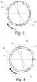
- Such angular variation is shown in the drawings illustrated in dotted lines on Figures 3 and 4 .
- the top weakness line 110 is asymmetric relative to the bottom weakness line 114 which is symmetric relative to a vertical plane crossing the diameter of the stopper 100. So when molding or further slitting the stopper 100, the top weakness line 110 is angularly switched or turned offset in relation with the position of the hinge(s) 118 of the bottom weakness line 114. Thus, one strip 108 (e.g., the left strip) in a clockwise screwing configuration, is shorter than the opposite strip 108 (e.g., the right strip). In other embodiments, such as show in Figure 3 , the bottom weakness line 114 is symmetric relative to a vertical plane crossing the diameter of the stopper 100 where the plane being shown by a fine continuous line.
Landscapes
- Engineering & Computer Science (AREA)
- Mechanical Engineering (AREA)
- Closures For Containers (AREA)
Description
- This invention relates to a tethered plastic screw stopper.
- In the field of liquid packaging, it is very common to seal the aperture of a container with a stopper, often made from a plastic material. Such container is usually a plastic or glass bottle, but other materials may be used as well.
- The stopper has a tubular shape closed at its top edge by a top wall. The stopper comprises a roof attached to a tamper shell through bridges. Bridges are distributed around the circumference of the roof and the tamper shall. The bridges may be made when molding the stopper or after through undergoing a cutting step during the manufacturing process.
- Usually the bottle neck includes outer fixation feature, such as thread(s) for screw type stopper or annular fixation rings for snap type stopper, to secure the stopper on the bottle neck.
- For screw type stoppers, the tamper shell comprises inner thread(s) arranged inside side walls. The bottle neck fixation feature may include outer thread(s). Such combination of outer and inner thread(s) allows the stopper to be screwed on a bottle neck to seal it and unscrewed for bottle opening. A snap type stopper may include an inner annular area and the bottle neck fixation feature may include outer fixation ring, in order to slot in force the stopper on the bottle neck. A snap type stopper may include a tamper shell with a movable sealing roof from a closed position to a partial opening position, and reversely. The roof may be separated upon opening or may be connected to the tamper shell.
- In a bottle sealing position of the stopper, the tamper shell may be secured around the bottle neck through inner shell retaining features or through the retaining features diameter being smaller than a diameter of a tamper shell of the bottle neck.
- The roof may be removable. During bottle opening, the bridges form a weakness line and may be torn apart from the roof, separating it from the bottle. The weakness line may be torn when user unscrews the tamper shell of the stopper or when user lifts the roof by tilting.
- There is a recycling risk with separable roof as consumers may not always screw or snap back the roof onto the bottle neck once empty. The stopper may be thrown away as litter or put into the trash bin, or worse make its way into a landfill, which is not good in view of the environmental considerations.
- One solution includes linking the roof to the tamper shell secured on the bottle neck, so the roof stays attached to the bottle after bottle opening. Such an attached stopper may be called a "tethered stopper."
-
U.S. Patent No. 9,010,555 -
U.S. 8,490,805 teaches a plastic screw stopper comprises a helicoidal strip between a tamper shell and a roof. Such helicoidal strip is obtained by cutting the tamper shell around the stopper. The outer wall of the tamper shell is placed against a blade and the stopper is moved in rotation relative to the blade according to an angular stroke greater than an entire turn or more than 360°. During rotation, the stopper is being moved in an axial movement relative to the blade. The cut line forms a helicoidal weakness line which remains attached at one end to the tamper shell and at its opposite end to the roof after opening.US20110297682 teaches a stopper with strips that are connected with a plurality of top and bottom bridges at different position along the strip.EP2331418 teaches a stopper with strips that have no top nor bottom bridge. - Other known art prior art systems include a tethered stopper comprising a spiral strip. The spiral strip is made during the stopper molding so there is no cutting or slitting operations. Other known prior art systems include tethered stoppers comprising two strips linking the closure shell to the tamper band secured on the bottle.
- This invention is a tethered plastic screw stopper where its closure shell remains attached to its tamper band after the bottle is opened by use of a strip made into the plastic material of the stopper between the tamper band and the closure shell using a bottom weakness line and a top weakness line. Each strip remains connected to the tamper band secured on the bottle neck by a least a bottom hinge managed into the bottom weakness line. The opposite ends of each strip are directly linked to the closure shell through a junction point.
- The stopper further comprises a specific top weakness line where the junction point of the strip with the closure shell is located over a bottom bridge located at the nearest from the bottom hinge(s), so called "nearest bottom bridge" on a side of the screwing direction of the closure shell.
- Thus, the invention systematically allows the nearest bottom bridge to be broken due to the junction point location where the closure shell and the strip ends are upwardly moved the farthest from the tamper band during closure shell unscrewing motion. A force is applied on the closest bridge due to the specific position of the junction point of the end of the strip.
- The figures are not necessarily to scale and some features may be exaggerated or minimized, such as to show details of particular components. Emphasis is placed on illustrating the principles of the invention. In the figures, like reference numerals designate corresponding parts throughout the different views.
-
Figure 1 is a diagrammatic lateral view of a tethered stopper in a closed position on a bottle. -
Figure 2 is a diagrammatic lateral view similar toFigure 1 during the opening of the stopper. -
Figure 3 is a diagrammatic horizontal cross section view along the bottom weakness line a tethered stopper. -
Figure 4 is a diagrammatic horizontal cross section view along the top weakness line of the tethered stopper. - As required, detailed embodiments of the present disclosure are disclosed herein. The disclosed embodiments are merely examples that may be embodied in various and alternative forms, and combinations thereof. As used herein, for example, exemplary, and similar terms, refer expansively to embodiments that serve as an illustration, specimen, model or pattern.
- In some instances, well-known components, systems, materials or methods have not been described in detail in order to avoid obscuring the present disclosure. Therefore, specific structural and functional details disclosed herein are not to be interpreted as limiting, but merely as a basis for the claims and as a representative basis for teaching one skilled in the art to variously employ the present disclosure.
- Phrasing such as 'configured to' perform a function, including in the claims, can include any or all of being sized, shaped, positioned in the arrangement, and comprising material to perform the function.
- Terms indicating quantity, such as 'first' or 'second' are used for exemplary and explanation purposes and are not intended to dictate the specific ordering of a component with respect to other components. Terms indicating position such as 'top' or 'bottom' and 'left' or right' are used for exemplary and explanation purposes with respect to other components.
- Various embodiments of the present disclosure are disclosed herein. The described embodiments are merely exemplary illustrations of implementations set for a clear understanding of the principles of the disclosure. Variations, modifications, and combinations may be made to the described embodiments without departing from the scope of the claims. All such variations, modifications, and combinations are included herein by the scope of this disclosure and the claims.
- This invention relates to a tethered
plastic screw stopper 100 for closing abottle neck 102. Thestopper 100 is integrally made of one plastic piece by a molding fabrication step. Other parts or elements of thestopper 100 can be further created into the entire plastic piece through a cutting or slitting step. - The
stopper 100 is a screw type and comprises inner fixation features, such as thread(s), designed to cooperate with outer complementary fixation features made on thebottle neck 102. - In some embodiments, as illustrated in
Figures 1 through 4 , the screwing direction of thestopper 100 is typically clockwise and extends from right to left. The screwing orientation is represented as a directional arrow inFigures 1 through 4 . The unscrewing direction of thestopper 100 oppositely extends relative to the screw direction, so counterclockwise from left to right. In other embodiments, the screwing direction can be designed counterclockwise. - The
stopper 100 comprises aclosure shell 104 and underneath atamper band 106. Thetamper band 106 and theclosure shell 104 are separably linked together by way of astrip 108. - In some embodiments, the
stopper 100 includes onestrip 108. In other embodiments, thestopper 100 includes two or more strips 108. For example, thestopper 100 includes twostrips 108 positioned on opposite sides of thestopper 100. The twostrips 108 can be positioned in a symmetrical or asymmetrical layout. - The
strip 108 is separably connected to theclosure shell 104 through a plurality oftop bridges 112 that form atop weakness line 110. Similarly, thestrip 108 is separably connected to thetamper band 106 through a plurality ofbottom bridges 116 that form abottom weakness line 114. - The
bottom weakness line 114 comprises at least onehinge 118 configured to connect thestrip 108 and thetamper band 106. In some embodiments, thebottom weakness line 114 comprises twohinges 118 where each hinge 118 connects arespective strip 108 to thetamper band 106. The two hinges 118 can be spaced through a hole or a less thick material managed into thetamper band 106 between the two hinges 118. - The
top bridges 112 andbottom bridges 116 are each configured to be stretched and ultimately broken when unscrewing theclosure shell 104. The top andbottom bridges bottom weakness lines - Each
strip 108 comprises an extremity at an end of thetop weakness line 110, linking thestrip 108 with theclosure shell 104 at ajunction point 120. For example, in the embodiment having twostrips 108, there is ajunction point 120 at each end of thetop weakness line 110, linking the extremity of eachstrip 108 to theclosure shell 104. - The
top weakness line 110 is configured in order to form anend 122 of thestrip 108 positioned above abottom bridge 116 located at the nearest to thehinge 118 on the left side of the hinge considering a clockwise screwing direction of theclosure shell 104. When facing the stopper looking at the hinge(s) 118, if the screw direction is clockwise, then the junction point of the left strip relative to thehinge 118 is located over the nearest left bottom bridge 116 (denoted with parallel vertical lines inFigure 2 ). - The end of the top weakness line located on the left of the
hinge 118 for a clockwise screwing stopper is angularly located between - 40° to 40° relative to the vertical axis of thebottom bridge 116 located at the nearest from thehinge 118. In some embodiments, thehinge 118 is more particularly located between - 20° to 20° relative to the vertical axis of thebottom bridge 116 located at the nearest from thehinge 118. For example, when looking at thehinge 118, thejunction point 120 of theleft strip 108 is angularly situated approximately 20° relative to the leftnearest bottom bridge 116. Such angular variation is shown in the drawings illustrated in dotted lines onFigures 3 and 4 . - In some embodiments, the
top weakness line 110 is asymmetric relative to thebottom weakness line 114 which is symmetric relative to a vertical plane crossing the diameter of thestopper 100. So when molding or further slitting thestopper 100, thetop weakness line 110 is angularly switched or turned offset in relation with the position of the hinge(s) 118 of thebottom weakness line 114. Thus, one strip 108 (e.g., the left strip) in a clockwise screwing configuration, is shorter than the opposite strip 108 (e.g., the right strip). In other embodiments, such as show inFigure 3 , thebottom weakness line 114 is symmetric relative to a vertical plane crossing the diameter of thestopper 100 where the plane being shown by a fine continuous line. - While various embodiments of the invention have been described, it will be apparent to those of ordinary skill in the art that many more embodiments and implementations are possible that are within the scope of the claims.
Claims (8)
- A tethered plastic screw stopper (100), comprising:a closure shell (104);a tamper band (106) separably connected to the closure shell (104) by a plurality of bridges (112, 116), namely a plurality of top bridges (112) that form a top weakness line (110) and a plurality of bottom bridges (116) that form a bottom weakness line (114), that connect a bottom edge of the closure shell (104) to a top edge of the tamper band (106), each of the bridges (112, 116) configured to be stretched and broken when the closure shell (104) is moved from a first orientation prior to opening to a second orientation after opening;a strip (108) made into the plastic material of the stopper (100) between the tamper band (106) and the closure shell (104) using the bottom weakness line (114), formed by the plurality of bottom bridges (116), and the top weakness line (110), formed bythe plurality of top bridges (112), top and bottom bridges (112, 116) being regularly or irregularly positioned around the perimeter of the top and bottom weakness lines (110, 114), respectively, whereinthe strip (108) is connected to the closure shell (104) at a junction point (120), the strip (108) comprising an extremity at an end of the top weakness line (110) positioned above a first set of bridges (116) located along the bottom weakness line, the extremity linking the strip (108) with the closure shell (104) at the junction point (120); and a hinge (118) linking the strip (108) and the tamper band (106), the hinge (118) being positioned beneath a set of bridges (112) located along the top weakness line (110), andwhen facing the stopper (100) and looking at the hinge (118), the end of the top weakness line (110) is located on the left of the hinge (118);characterized in thatsaid end of the top weakness line (110) is angularly positioned within 40° of the vertical axis of the bottom bridge (116) located at the nearest from the hinge (118) considering a clockwise screwing motion configuration.
- The tethered plastic screw stopper (100) according to claim 1, wherein the end of the top weakness line (110) is located on the left of the hinge (118) and is angularly positioned within 20° of the vertical axis of the bottom bridge (116) located at the nearest from the hinge (118) considering a clockwise screwing motion configuration.
- The tethered plastic screw stopper (100) according to claim 1, wherein:the strip (108) is a first strip, the screw stopper (100) further comprises a second strip (108) having an extremity at the other end of the top weakness line (110), linking the second strip with the closure shell (104) at a second junction point (120),the bottom weakness line (114) comprises two hinges (118), where each hinge (118) connects a respective strip (108) to the tamper band (106),the second strip (108) is separably connected to the closure shell (104) through the top weakness line (110) and to the tamper band (106) through the bottom weakness line (114) and the second strip (108) is positioned opposite the first strip (108) about a diameter of the tamper band (106).
- The tethered plastic stopper (100) according to claim 3, wherein the two strips (108) are positioned on opposite sides of the stopper (100), in a symmetrical layout
- The tethered plastic stopper (100) according to claim 3, wherein, when looking at the hinges (118), the junction point (120) of the left strip is angularly situated approximately 20° relative to the bottom bridge (116) located at the nearest from the bottom hinge (118).
- The tethered plastic stopper (100) according to any of the preceding claims, wherein the stopper (100) is a screw type and comprises inner fixation features, such as thread(s), designed to cooperate with outer complementary fixation features made on the bottle neck.
- The tethered plastic stopper (100) according to any of the preceding claims, wherein the strip (108) is separably connected to the closure shell (104) through a plurality of top bridges (112) that form the top weakness line (110), and, similarly, is separably connected to the tamper band (106) through a plurality of bottom bridges (116) that form the bottom weakness line (114).
- The tethered plastic stopper (100) according to any of claims 3 to 9, wherein each of the two strips (108), is separably connected to the closure shell (104) through a plurality of top bridges (112) that form the top weakness line (110), and, similarly, is separably connected to the tamper band (106) through a plurality of bottom bridges (116) that form the bottom weakness line (114).
Applications Claiming Priority (3)
| Application Number | Priority Date | Filing Date | Title |
|---|---|---|---|
| US201862759931P | 2018-11-12 | 2018-11-12 | |
| EP19884687.5A EP3880575B1 (en) | 2018-11-12 | 2019-11-12 | Tethered plastic screw stopper |
| PCT/US2019/060808 WO2020102122A2 (en) | 2018-11-12 | 2019-11-12 | Tethered plastic screw stopper |
Related Parent Applications (2)
| Application Number | Title | Priority Date | Filing Date |
|---|---|---|---|
| EP19884687.5A Division-Into EP3880575B1 (en) | 2018-11-12 | 2019-11-12 | Tethered plastic screw stopper |
| EP19884687.5A Division EP3880575B1 (en) | 2018-11-12 | 2019-11-12 | Tethered plastic screw stopper |
Publications (4)
| Publication Number | Publication Date |
|---|---|
| EP4234431A2 EP4234431A2 (en) | 2023-08-30 |
| EP4234431A3 EP4234431A3 (en) | 2023-09-20 |
| EP4234431C0 EP4234431C0 (en) | 2024-08-28 |
| EP4234431B1 true EP4234431B1 (en) | 2024-08-28 |
Family
ID=70731706
Family Applications (3)
| Application Number | Title | Priority Date | Filing Date |
|---|---|---|---|
| EP24180692.6A Pending EP4403487A3 (en) | 2018-11-12 | 2019-11-12 | Tethered plastic screw stopper |
| EP19884687.5A Active EP3880575B1 (en) | 2018-11-12 | 2019-11-12 | Tethered plastic screw stopper |
| EP23171082.3A Active EP4234431B1 (en) | 2018-11-12 | 2019-11-12 | Tethered plastic screw stopper |
Family Applications Before (2)
| Application Number | Title | Priority Date | Filing Date |
|---|---|---|---|
| EP24180692.6A Pending EP4403487A3 (en) | 2018-11-12 | 2019-11-12 | Tethered plastic screw stopper |
| EP19884687.5A Active EP3880575B1 (en) | 2018-11-12 | 2019-11-12 | Tethered plastic screw stopper |
Country Status (6)
| Country | Link |
|---|---|
| US (1) | US20210394970A1 (en) |
| EP (3) | EP4403487A3 (en) |
| CA (1) | CA3111602A1 (en) |
| ES (1) | ES2956518T3 (en) |
| MX (1) | MX2021003759A (en) |
| WO (1) | WO2020102122A2 (en) |
Families Citing this family (4)
| Publication number | Priority date | Publication date | Assignee | Title |
|---|---|---|---|---|
| US20220041339A1 (en) * | 2020-08-07 | 2022-02-10 | Niagara Bottling, Llc | Single anchor closure |
| US20220177199A1 (en) * | 2020-12-04 | 2022-06-09 | Niagara Bottling, Llc | Multiple asymmetric anchor container closure |
| ES1289137Y (en) * | 2022-03-18 | 2022-06-29 | Betapack S A U | Closing cap for pouring holes in liquid containers |
| WO2025007033A2 (en) * | 2023-06-29 | 2025-01-02 | Niagara Bottling, Llc | Container closure |
Citations (8)
| Publication number | Priority date | Publication date | Assignee | Title |
|---|---|---|---|---|
| US3904062A (en) | 1973-07-02 | 1975-09-09 | Somepla Sa | Tamper-proof and loss-proof screw-type bottle cap |
| US5725115A (en) | 1995-02-21 | 1998-03-10 | Crown Cork Ag | Closure cap with tether |
| USD613162S1 (en) | 2008-06-17 | 2010-04-06 | Creanova Universal Closures Ltd. | Closure |
| US20110174760A1 (en) | 2008-10-09 | 2011-07-21 | Tetra Laval Holdings & Finance S.A. | Stopper having a subdivided line of weakness and a method of fabricating such a stopper |
| US20110297682A1 (en) | 2007-06-22 | 2011-12-08 | Si Joong Kwon | Container with anti-loss and anti-idle-rotation cap |
| US20150251827A1 (en) | 2014-03-10 | 2015-09-10 | Phillip John Campbell | Closure with spring loaded tether docking |
| WO2019207153A2 (en) | 2018-04-26 | 2019-10-31 | Obrist Closures Switzerland Gmbh | Closure |
| WO2021074726A1 (en) * | 2019-10-18 | 2021-04-22 | Novembal Usa Inc. | Tethered plastic screw stopper |
Family Cites Families (16)
| Publication number | Priority date | Publication date | Assignee | Title |
|---|---|---|---|---|
| US4805792A (en) * | 1984-04-17 | 1989-02-21 | Continental White Cap, Inc. | Litterless tamper indicating closure |
| US4557393A (en) * | 1984-04-17 | 1985-12-10 | Continental White Cap, Inc. | Snap-on cap with tethering strap |
| USRE32879E (en) * | 1988-02-24 | 1989-02-28 | Sunbeam Plastics Corporation | Tamper indicating screw cap |
| GB8916099D0 (en) * | 1989-07-13 | 1989-08-31 | Metal Closures Group Ltd | Closure for containers |
| FR2832984B1 (en) * | 2001-12-05 | 2004-01-30 | Sobem | CAPPING CAP (10) WITH CAP (11) |
| FR2923172B1 (en) | 2007-11-06 | 2009-12-11 | Tetra Laval Holdings & Finance | METHOD AND MACHINE FOR MANUFACTURING A CAP FOR A COLLAR OF A CONTAINER, AND A PLUG AS OBTAINED THEREBY |
| CN201136626Y (en) * | 2008-01-03 | 2008-10-22 | 黄开刚 | Multifunctional plastic antifake bottle cap |
| AU2010322960A1 (en) | 2009-11-27 | 2012-06-14 | Tetra Laval Holdings & Finance S.A. | Lid having a break line |
| FR2957587B1 (en) * | 2010-03-22 | 2012-07-13 | Tetra Laval Holdings & Finance | CAP WITH WEAKENING LINE |
| CN102700822A (en) * | 2012-05-15 | 2012-10-03 | 李红彪 | bottle cap |
| CN102700823A (en) * | 2012-05-15 | 2012-10-03 | 李红彪 | a bottle cap |
| WO2015061834A1 (en) * | 2013-10-31 | 2015-05-07 | Doran Brian | Capping device for a container |
| US10836549B2 (en) * | 2015-04-02 | 2020-11-17 | Thiscap Inc. | Cap for container |
| CN105015912B (en) * | 2015-08-04 | 2017-12-19 | 泉州华硕实业有限公司 | A kind of anti-fake bottle lid |
| KR101880107B1 (en) * | 2016-12-16 | 2018-07-19 | 성보연 | Container cap easily separate collection |
| US10836544B2 (en) * | 2018-05-09 | 2020-11-17 | Silgan White Cap LLC | Closure with hinge |
-
2019
- 2019-11-12 ES ES23171082T patent/ES2956518T3/en active Active
- 2019-11-12 US US17/292,784 patent/US20210394970A1/en not_active Abandoned
- 2019-11-12 EP EP24180692.6A patent/EP4403487A3/en active Pending
- 2019-11-12 WO PCT/US2019/060808 patent/WO2020102122A2/en not_active Ceased
- 2019-11-12 EP EP19884687.5A patent/EP3880575B1/en active Active
- 2019-11-12 MX MX2021003759A patent/MX2021003759A/en unknown
- 2019-11-12 CA CA3111602A patent/CA3111602A1/en active Pending
- 2019-11-12 EP EP23171082.3A patent/EP4234431B1/en active Active
Patent Citations (9)
| Publication number | Priority date | Publication date | Assignee | Title |
|---|---|---|---|---|
| US3904062A (en) | 1973-07-02 | 1975-09-09 | Somepla Sa | Tamper-proof and loss-proof screw-type bottle cap |
| US5725115A (en) | 1995-02-21 | 1998-03-10 | Crown Cork Ag | Closure cap with tether |
| US20110297682A1 (en) | 2007-06-22 | 2011-12-08 | Si Joong Kwon | Container with anti-loss and anti-idle-rotation cap |
| USD613162S1 (en) | 2008-06-17 | 2010-04-06 | Creanova Universal Closures Ltd. | Closure |
| US20110174760A1 (en) | 2008-10-09 | 2011-07-21 | Tetra Laval Holdings & Finance S.A. | Stopper having a subdivided line of weakness and a method of fabricating such a stopper |
| US9010555B2 (en) * | 2008-10-09 | 2015-04-21 | Tetra Laval Holdings & Finance S.A. | Stopper having a subdivided line of weakness and a method of fabricating such a stopper |
| US20150251827A1 (en) | 2014-03-10 | 2015-09-10 | Phillip John Campbell | Closure with spring loaded tether docking |
| WO2019207153A2 (en) | 2018-04-26 | 2019-10-31 | Obrist Closures Switzerland Gmbh | Closure |
| WO2021074726A1 (en) * | 2019-10-18 | 2021-04-22 | Novembal Usa Inc. | Tethered plastic screw stopper |
Non-Patent Citations (2)
| Title |
|---|
| ANONYMOUS: "Beverage closure matrix ", HUSKY, 1 May 2020 (2020-05-01), pages 1 - 8, XP093284732, Retrieved from the Internet <URL:https://www.husky.co/siteassets/documents/beverage-closures-portfolio.pdf> [retrieved on 20250606] |
| D7 - Proprietors reply to Official Communication |
Also Published As
| Publication number | Publication date |
|---|---|
| US20210394970A1 (en) | 2021-12-23 |
| EP3880575B1 (en) | 2024-07-10 |
| EP4403487A2 (en) | 2024-07-24 |
| MX2021003759A (en) | 2021-05-27 |
| WO2020102122A2 (en) | 2020-05-22 |
| EP3880575A2 (en) | 2021-09-22 |
| EP4234431A3 (en) | 2023-09-20 |
| EP4403487A3 (en) | 2024-10-23 |
| EP4234431C0 (en) | 2024-08-28 |
| EP4234431A2 (en) | 2023-08-30 |
| EP3880575A4 (en) | 2022-08-03 |
| ES2956518T1 (en) | 2023-12-22 |
| ES2956518T3 (en) | 2025-02-13 |
| CA3111602A1 (en) | 2020-05-22 |
| WO2020102122A3 (en) | 2020-07-23 |
Similar Documents
| Publication | Publication Date | Title |
|---|---|---|
| EP3877279B1 (en) | Tethered plastic screw stopper | |
| EP4234431B1 (en) | Tethered plastic screw stopper | |
| US20240067423A1 (en) | Tethered plastic screw stopper | |
| WO2019207152A1 (en) | Closure | |
| WO2021074726A1 (en) | Tethered plastic screw stopper | |
| WO2020041640A1 (en) | Tethered stopper and method for making thereof | |
| US20220048681A1 (en) | Tethered plastic stopper | |
| US20210316908A1 (en) | Tethered plastic stopper | |
| US20210206537A1 (en) | Tethered plastic stopper | |
| WO2021074728A1 (en) | Tethered plastic screw stopper | |
| WO2021074727A1 (en) | Tethered plastic closure | |
| US20230056087A1 (en) | Hinged stopper | |
| EP3853141B1 (en) | Tethered plastic stopper | |
| EP4422984A1 (en) | Plastic tethered stopper for a container | |
| CN109689524B (en) | Closures with Tamper-evident Parts | |
| JP6875380B2 (en) | Assembly of containers and reusable tamper-opening explicit closures | |
| WO2020061579A1 (en) | Tethered plastic stopper | |
| RU2783612C1 (en) | Lid for closing the container | |
| WO2020061582A1 (en) | Tethered plastic stopper |
Legal Events
| Date | Code | Title | Description |
|---|---|---|---|
| PUAI | Public reference made under article 153(3) epc to a published international application that has entered the european phase |
Free format text: ORIGINAL CODE: 0009012 |
|
| STAA | Information on the status of an ep patent application or granted ep patent |
Free format text: STATUS: REQUEST FOR EXAMINATION WAS MADE |
|
| REG | Reference to a national code |
Free format text: PREVIOUS MAIN CLASS: B65D0055160000 Ref country code: DE Ref legal event code: R079 Ref document number: 602019058168 Country of ref document: DE Free format text: PREVIOUS MAIN CLASS: B65D0055160000 Ipc: B65D0041340000 |
|
| PUAL | Search report despatched |
Free format text: ORIGINAL CODE: 0009013 |
|
| 17P | Request for examination filed |
Effective date: 20230502 |
|
| AC | Divisional application: reference to earlier application |
Ref document number: 3880575 Country of ref document: EP Kind code of ref document: P |
|
| AK | Designated contracting states |
Kind code of ref document: A2 Designated state(s): AL AT BE BG CH CY CZ DE DK EE ES FI FR GB GR HR HU IE IS IT LI LT LU LV MC MK MT NL NO PL PT RO RS SE SI SK SM TR |
|
| STAA | Information on the status of an ep patent application or granted ep patent |
Free format text: STATUS: EXAMINATION IS IN PROGRESS |
|
| AK | Designated contracting states |
Kind code of ref document: A3 Designated state(s): AL AT BE BG CH CY CZ DE DK EE ES FI FR GB GR HR HU IE IS IT LI LT LU LV MC MK MT NL NO PL PT RO RS SE SI SK SM TR |
|
| RIC1 | Information provided on ipc code assigned before grant |
Ipc: B65D 55/16 20060101ALI20230811BHEP Ipc: B65D 41/34 20060101AFI20230811BHEP |
|
| 17Q | First examination report despatched |
Effective date: 20230831 |
|
| REG | Reference to a national code |
Ref country code: ES Ref legal event code: BA2A Ref document number: 2956518 Country of ref document: ES Kind code of ref document: T1 Effective date: 20231222 |
|
| GRAP | Despatch of communication of intention to grant a patent |
Free format text: ORIGINAL CODE: EPIDOSNIGR1 |
|
| STAA | Information on the status of an ep patent application or granted ep patent |
Free format text: STATUS: GRANT OF PATENT IS INTENDED |
|
| INTG | Intention to grant announced |
Effective date: 20240307 |
|
| GRAS | Grant fee paid |
Free format text: ORIGINAL CODE: EPIDOSNIGR3 |
|
| RBV | Designated contracting states (corrected) |
Designated state(s): AL AT BE BG CH CY CZ DE DK EE ES FI FR GB GR HR HU IE IS IT LI LT LU LV MC MK MT NL NO PL PT RO RS SE SI SK SM TR |
|
| GRAA | (expected) grant |
Free format text: ORIGINAL CODE: 0009210 |
|
| STAA | Information on the status of an ep patent application or granted ep patent |
Free format text: STATUS: THE PATENT HAS BEEN GRANTED |
|
| RAP1 | Party data changed (applicant data changed or rights of an application transferred) |
Owner name: SIDEL PARTICIPATIONS SAS |
|
| AC | Divisional application: reference to earlier application |
Ref document number: 3880575 Country of ref document: EP Kind code of ref document: P |
|
| AK | Designated contracting states |
Kind code of ref document: B1 Designated state(s): AL AT BE BG CH CY CZ DE DK EE ES FI FR GB GR HR HU IE IS IT LI LT LU LV MC MK MT NL NO PL PT RO RS SE SI SK SM TR |
|
| REG | Reference to a national code |
Ref country code: CH Ref legal event code: EP |
|
| REG | Reference to a national code |
Ref country code: DE Ref legal event code: R096 Ref document number: 602019058168 Country of ref document: DE |
|
| REG | Reference to a national code |
Ref country code: IE Ref legal event code: FG4D |
|
| U01 | Request for unitary effect filed |
Effective date: 20240927 |
|
| U07 | Unitary effect registered |
Designated state(s): AT BE BG DE DK EE FI FR IT LT LU LV MT NL PT RO SE SI Effective date: 20241104 |
|
| PG25 | Lapsed in a contracting state [announced via postgrant information from national office to epo] |
Ref country code: NO Free format text: LAPSE BECAUSE OF FAILURE TO SUBMIT A TRANSLATION OF THE DESCRIPTION OR TO PAY THE FEE WITHIN THE PRESCRIBED TIME-LIMIT Effective date: 20241128 |
|
| PG25 | Lapsed in a contracting state [announced via postgrant information from national office to epo] |
Ref country code: GR Free format text: LAPSE BECAUSE OF FAILURE TO SUBMIT A TRANSLATION OF THE DESCRIPTION OR TO PAY THE FEE WITHIN THE PRESCRIBED TIME-LIMIT Effective date: 20241129 Ref country code: PL Free format text: LAPSE BECAUSE OF FAILURE TO SUBMIT A TRANSLATION OF THE DESCRIPTION OR TO PAY THE FEE WITHIN THE PRESCRIBED TIME-LIMIT Effective date: 20240828 |
|
| U20 | Renewal fee for the european patent with unitary effect paid |
Year of fee payment: 6 Effective date: 20241218 |
|
| PG25 | Lapsed in a contracting state [announced via postgrant information from national office to epo] |
Ref country code: IS Free format text: LAPSE BECAUSE OF FAILURE TO SUBMIT A TRANSLATION OF THE DESCRIPTION OR TO PAY THE FEE WITHIN THE PRESCRIBED TIME-LIMIT Effective date: 20241228 |
|
| PG25 | Lapsed in a contracting state [announced via postgrant information from national office to epo] |
Ref country code: HR Free format text: LAPSE BECAUSE OF FAILURE TO SUBMIT A TRANSLATION OF THE DESCRIPTION OR TO PAY THE FEE WITHIN THE PRESCRIBED TIME-LIMIT Effective date: 20240828 |
|
| PG25 | Lapsed in a contracting state [announced via postgrant information from national office to epo] |
Ref country code: RS Free format text: LAPSE BECAUSE OF FAILURE TO SUBMIT A TRANSLATION OF THE DESCRIPTION OR TO PAY THE FEE WITHIN THE PRESCRIBED TIME-LIMIT Effective date: 20241128 |
|
| PG25 | Lapsed in a contracting state [announced via postgrant information from national office to epo] |
Ref country code: RS Free format text: LAPSE BECAUSE OF FAILURE TO SUBMIT A TRANSLATION OF THE DESCRIPTION OR TO PAY THE FEE WITHIN THE PRESCRIBED TIME-LIMIT Effective date: 20241128 Ref country code: PL Free format text: LAPSE BECAUSE OF FAILURE TO SUBMIT A TRANSLATION OF THE DESCRIPTION OR TO PAY THE FEE WITHIN THE PRESCRIBED TIME-LIMIT Effective date: 20240828 Ref country code: NO Free format text: LAPSE BECAUSE OF FAILURE TO SUBMIT A TRANSLATION OF THE DESCRIPTION OR TO PAY THE FEE WITHIN THE PRESCRIBED TIME-LIMIT Effective date: 20241128 Ref country code: IS Free format text: LAPSE BECAUSE OF FAILURE TO SUBMIT A TRANSLATION OF THE DESCRIPTION OR TO PAY THE FEE WITHIN THE PRESCRIBED TIME-LIMIT Effective date: 20241228 Ref country code: HR Free format text: LAPSE BECAUSE OF FAILURE TO SUBMIT A TRANSLATION OF THE DESCRIPTION OR TO PAY THE FEE WITHIN THE PRESCRIBED TIME-LIMIT Effective date: 20240828 Ref country code: GR Free format text: LAPSE BECAUSE OF FAILURE TO SUBMIT A TRANSLATION OF THE DESCRIPTION OR TO PAY THE FEE WITHIN THE PRESCRIBED TIME-LIMIT Effective date: 20241129 |
|
| REG | Reference to a national code |
Ref country code: ES Ref legal event code: FG2A Ref document number: 2956518 Country of ref document: ES Kind code of ref document: T3 Effective date: 20250213 |
|
| PG25 | Lapsed in a contracting state [announced via postgrant information from national office to epo] |
Ref country code: SM Free format text: LAPSE BECAUSE OF FAILURE TO SUBMIT A TRANSLATION OF THE DESCRIPTION OR TO PAY THE FEE WITHIN THE PRESCRIBED TIME-LIMIT Effective date: 20240828 |
|
| PG25 | Lapsed in a contracting state [announced via postgrant information from national office to epo] |
Ref country code: CZ Free format text: LAPSE BECAUSE OF FAILURE TO SUBMIT A TRANSLATION OF THE DESCRIPTION OR TO PAY THE FEE WITHIN THE PRESCRIBED TIME-LIMIT Effective date: 20240828 |
|
| PG25 | Lapsed in a contracting state [announced via postgrant information from national office to epo] |
Ref country code: SK Free format text: LAPSE BECAUSE OF FAILURE TO SUBMIT A TRANSLATION OF THE DESCRIPTION OR TO PAY THE FEE WITHIN THE PRESCRIBED TIME-LIMIT Effective date: 20240828 |
|
| PLBI | Opposition filed |
Free format text: ORIGINAL CODE: 0009260 |
|
| PLAX | Notice of opposition and request to file observation + time limit sent |
Free format text: ORIGINAL CODE: EPIDOSNOBS2 |
|
| PG25 | Lapsed in a contracting state [announced via postgrant information from national office to epo] |
Ref country code: MC Free format text: LAPSE BECAUSE OF FAILURE TO SUBMIT A TRANSLATION OF THE DESCRIPTION OR TO PAY THE FEE WITHIN THE PRESCRIBED TIME-LIMIT Effective date: 20240828 |
|
| 26 | Opposition filed |
Opponent name: ARNOLD & SIEDSMA B.V. Effective date: 20250528 |
|
| GBPC | Gb: european patent ceased through non-payment of renewal fee |
Effective date: 20241128 |
|
| PG25 | Lapsed in a contracting state [announced via postgrant information from national office to epo] |
Ref country code: GB Free format text: LAPSE BECAUSE OF NON-PAYMENT OF DUE FEES Effective date: 20241128 |
|
| PLBB | Reply of patent proprietor to notice(s) of opposition received |
Free format text: ORIGINAL CODE: EPIDOSNOBS3 |
|
| PG25 | Lapsed in a contracting state [announced via postgrant information from national office to epo] |
Ref country code: IE Free format text: LAPSE BECAUSE OF NON-PAYMENT OF DUE FEES Effective date: 20241112 |
|
| U20 | Renewal fee for the european patent with unitary effect paid |
Year of fee payment: 7 Effective date: 20251022 |
|
| REG | Reference to a national code |
Ref country code: CH Ref legal event code: U11 Free format text: ST27 STATUS EVENT CODE: U-0-0-U10-U11 (AS PROVIDED BY THE NATIONAL OFFICE) Effective date: 20251201 |
|
| PGFP | Annual fee paid to national office [announced via postgrant information from national office to epo] |
Ref country code: CH Payment date: 20251201 Year of fee payment: 7 |
|
| PGFP | Annual fee paid to national office [announced via postgrant information from national office to epo] |
Ref country code: ES Payment date: 20251201 Year of fee payment: 7 |