EP4234271B1 - Motorcycle tyre set - Google Patents
Motorcycle tyre set Download PDFInfo
- Publication number
- EP4234271B1 EP4234271B1 EP23151225.2A EP23151225A EP4234271B1 EP 4234271 B1 EP4234271 B1 EP 4234271B1 EP 23151225 A EP23151225 A EP 23151225A EP 4234271 B1 EP4234271 B1 EP 4234271B1
- Authority
- EP
- European Patent Office
- Prior art keywords
- tyre
- rubber
- wheel
- wheel tyre
- crown
- Prior art date
- Legal status (The legal status is an assumption and is not a legal conclusion. Google has not performed a legal analysis and makes no representation as to the accuracy of the status listed.)
- Active
Links
Images


Classifications
-
- B—PERFORMING OPERATIONS; TRANSPORTING
- B60—VEHICLES IN GENERAL
- B60C—VEHICLE TYRES; TYRE INFLATION; TYRE CHANGING; CONNECTING VALVES TO INFLATABLE ELASTIC BODIES IN GENERAL; DEVICES OR ARRANGEMENTS RELATED TO TYRES
- B60C19/00—Tyre parts or constructions not otherwise provided for
- B60C19/001—Tyres requiring an asymmetric or a special mounting
-
- B—PERFORMING OPERATIONS; TRANSPORTING
- B60—VEHICLES IN GENERAL
- B60C—VEHICLE TYRES; TYRE INFLATION; TYRE CHANGING; CONNECTING VALVES TO INFLATABLE ELASTIC BODIES IN GENERAL; DEVICES OR ARRANGEMENTS RELATED TO TYRES
- B60C11/00—Tyre tread bands; Tread patterns; Anti-skid inserts
- B60C11/0008—Tyre tread bands; Tread patterns; Anti-skid inserts characterised by the tread rubber
-
- B—PERFORMING OPERATIONS; TRANSPORTING
- B60—VEHICLES IN GENERAL
- B60C—VEHICLE TYRES; TYRE INFLATION; TYRE CHANGING; CONNECTING VALVES TO INFLATABLE ELASTIC BODIES IN GENERAL; DEVICES OR ARRANGEMENTS RELATED TO TYRES
- B60C11/00—Tyre tread bands; Tread patterns; Anti-skid inserts
- B60C11/0041—Tyre tread bands; Tread patterns; Anti-skid inserts comprising different tread rubber layers
- B60C11/005—Tyre tread bands; Tread patterns; Anti-skid inserts comprising different tread rubber layers with cap and base layers
- B60C11/0058—Tyre tread bands; Tread patterns; Anti-skid inserts comprising different tread rubber layers with cap and base layers with different cap rubber layers in the axial direction
-
- B—PERFORMING OPERATIONS; TRANSPORTING
- B60—VEHICLES IN GENERAL
- B60C—VEHICLE TYRES; TYRE INFLATION; TYRE CHANGING; CONNECTING VALVES TO INFLATABLE ELASTIC BODIES IN GENERAL; DEVICES OR ARRANGEMENTS RELATED TO TYRES
- B60C9/00—Reinforcements or ply arrangement of pneumatic tyres
- B60C9/02—Carcasses
- B60C9/023—Carcasses built up from narrow strips, individual cords or filaments, e.g. using filament winding
-
- B—PERFORMING OPERATIONS; TRANSPORTING
- B60—VEHICLES IN GENERAL
- B60C—VEHICLE TYRES; TYRE INFLATION; TYRE CHANGING; CONNECTING VALVES TO INFLATABLE ELASTIC BODIES IN GENERAL; DEVICES OR ARRANGEMENTS RELATED TO TYRES
- B60C9/00—Reinforcements or ply arrangement of pneumatic tyres
- B60C9/02—Carcasses
- B60C9/0238—Carcasses characterised by special physical properties of the carcass ply
-
- B—PERFORMING OPERATIONS; TRANSPORTING
- B60—VEHICLES IN GENERAL
- B60C—VEHICLE TYRES; TYRE INFLATION; TYRE CHANGING; CONNECTING VALVES TO INFLATABLE ELASTIC BODIES IN GENERAL; DEVICES OR ARRANGEMENTS RELATED TO TYRES
- B60C9/00—Reinforcements or ply arrangement of pneumatic tyres
- B60C9/02—Carcasses
- B60C9/04—Carcasses the reinforcing cords of each carcass ply arranged in a substantially parallel relationship
- B60C9/06—Carcasses the reinforcing cords of each carcass ply arranged in a substantially parallel relationship the cords extend diagonally from bead to bead and run in opposite directions in each successive carcass ply, i.e. bias angle ply
-
- B—PERFORMING OPERATIONS; TRANSPORTING
- B60—VEHICLES IN GENERAL
- B60C—VEHICLE TYRES; TYRE INFLATION; TYRE CHANGING; CONNECTING VALVES TO INFLATABLE ELASTIC BODIES IN GENERAL; DEVICES OR ARRANGEMENTS RELATED TO TYRES
- B60C9/00—Reinforcements or ply arrangement of pneumatic tyres
- B60C9/02—Carcasses
- B60C2009/0269—Physical properties or dimensions of the carcass coating rubber
- B60C2009/0276—Modulus; Hardness; Loss modulus or "tangens delta"
-
- B—PERFORMING OPERATIONS; TRANSPORTING
- B60—VEHICLES IN GENERAL
- B60C—VEHICLE TYRES; TYRE INFLATION; TYRE CHANGING; CONNECTING VALVES TO INFLATABLE ELASTIC BODIES IN GENERAL; DEVICES OR ARRANGEMENTS RELATED TO TYRES
- B60C9/00—Reinforcements or ply arrangement of pneumatic tyres
- B60C9/18—Structure or arrangement of belts or breakers, crown-reinforcing or cushioning layers
- B60C2009/1828—Structure or arrangement of belts or breakers, crown-reinforcing or cushioning layers characterised by special physical properties of the belt ply
-
- B—PERFORMING OPERATIONS; TRANSPORTING
- B60—VEHICLES IN GENERAL
- B60C—VEHICLE TYRES; TYRE INFLATION; TYRE CHANGING; CONNECTING VALVES TO INFLATABLE ELASTIC BODIES IN GENERAL; DEVICES OR ARRANGEMENTS RELATED TO TYRES
- B60C11/00—Tyre tread bands; Tread patterns; Anti-skid inserts
- B60C11/0008—Tyre tread bands; Tread patterns; Anti-skid inserts characterised by the tread rubber
- B60C2011/0016—Physical properties or dimensions
-
- B—PERFORMING OPERATIONS; TRANSPORTING
- B60—VEHICLES IN GENERAL
- B60C—VEHICLE TYRES; TYRE INFLATION; TYRE CHANGING; CONNECTING VALVES TO INFLATABLE ELASTIC BODIES IN GENERAL; DEVICES OR ARRANGEMENTS RELATED TO TYRES
- B60C2200/00—Tyres specially adapted for particular applications
- B60C2200/10—Tyres specially adapted for particular applications for motorcycles, scooters or the like
Definitions
- the present invention is related to a motorcycle tyre set.
- Patent Document 1 invention a motorcycle tyre set that includes a front-wheel tyre and a rear-wheel tyre.
- the front-wheel tyre and the rear-wheel tyre each include a toroidal carcass and a band layer arranged outwardly in the tyre radial direction of the carcass.
- Each carcass has carcass cords oriented at an angle of from 20 to 70 degrees with respect to the tyre circumferential direction.
- Each band layer includes a jointless band ply.
- the angle of the carcass cords of the front-wheel tyre is smaller than the angle of the carcass cords of the rear-wheel tyre.
- Patent document 1 Japanese Unexamined Patent Application Publication 2020-175860
- a motorcycle tyre set in accordance with the preamble of claim 1 is known from US 2020/331298 A1 .
- Related motorcycle tyre sets are known from JP 2001 138706 A and EP 3 789 216 A1 .
- a related motorcycle tyre is known from JP 4 976001 B2 .
- the present invention has been made in view of the above circumstances and has a major object to provide a motorcycle tyre set capable of improving high-speed stability performance and turning performance.
- a motorcycle tyre set includes a front-wheel tyre; and a rear-wheel tyre.
- Each of the front-wheel tyre and the rear-wheel tyre includes a tread portion, a toroidal carcass, a band layer arranged outwardly in a tyre radial direction of the carcass in the tread portion, and a tread rubber arranged outwardly in the tyre radial direction of the band layer.
- the carcass includes a carcass ply including a plurality of carcass cords.
- the band layer includes a jointless band ply in which a band cord is wound spirally in a tyre circumferential direction at an angle equal to or less than 5 degrees.
- the tread rubber includes a crown rubber portion disposed in a tread crown region.
- Each of the front-wheel tyre and the rear-wheel tyre further comprises a pair of shoulder rubber portions arranged on both sides of crown rubber portions in a tyre axial direction.
- An angle ⁇ 1 of the plurality of carcass cords of the front-wheel tyre is equal to or less than 65 degrees with respect to the tyre circumferential direction.
- a rubber hardness Hc2 of the crown rubber portion of the rear-wheel tyre is greater than a rubber hardness Hc1 of the crown rubber portion of the front-wheel tyre.
- the rubber hardness Hc1 of the crown rubber portion is different from the rubber hardness Hs1 of the pair of shoulder rubber portions.
- a rubber hardness Hc2 of the crown rubber portion is different from a rubber hardness Hs2 of the pair of shoulder rubber portions.
- the rubber hardness is measured by Durometer Type A at 23 degrees C based on JIS-K6253.
- a difference (Hc2 - Hc1) between the rubber hardness Hc2 of the crown rubber portion of the rear-wheel tyre and the rubber hardness Hc1 of the crown rubber portion of the front-wheel tyre is in a range from 2 to 8.
- the angle ⁇ 1 of the plurality of carcass cords of the front-wheel tyre is smaller than an angle ⁇ 2 of the plurality of carcass cords of the rear-wheel tyre with respect to the tyre circumferential direction.
- a difference ( ⁇ 2 - ⁇ 1) between the angle ⁇ 2 of the plurality of carcass cords of the rear-wheel tyre and the angle ⁇ 1 of the plurality of carcass cords of the front-wheel tyre is equal to or more than 15 degrees.
- each of the front-wheel tyre and the rear-wheel tyre further comprises a base rubber portion arranged inwardly in the tyre radial direction of the crown rubber portion and the pair of shoulder rubber portions, and a rubber hardness of the base rubber is different from the rubber hardness of the crown rubber portion and the rubber hardness of the pair of shoulder rubber portions.
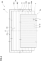
- FIG. 1 illustrates a tyre meridian cross-sectional view of a front-wheel tyre S1 showing an embodiment of a motorcycle tyre set (hereinafter simply referred to as "tyre set") S in accordance with the present invention.
- FIG. 2 illustrates a tyre meridian cross-sectional view of a rear-wheel tyre S2 showing an embodiment of the tyre set S in accordance with the present invention.
- the tyre set S according to the present embodiment of the invention is suitable for use, for example, in the sports category for circuit driving. However, the tyre set S according to the present invention is not limited to such an aspect of use.
- FIG. 1 and FIG. 2 show the front-wheel tyre S1 and the rear-wheel tyre S2 which are under a normal state.
- the "normal state" of a tyre is such that the tyre is mounted on a standard wheel rim with a standard pressure but loaded with no tyre load.
- the dimensions of portions of each tyre are values measured under the normal state.
- the "standard wheel rim” is a wheel rim officially approved for each tyre by standards organizations on which the tyre is based, wherein the standard wheel rim is the "standard rim” specified in JATMA, the "Design Rim” in TYRE, and the “Measuring Rim” in ETRTO, for example.
- the "standard pressure” is a standard pressure officially approved for each tyre by standards organizations on which the tyre is based, wherein the standard pressure is the "maximum air pressure” in JATMA, the maximum pressure given in the "Tyre Load Limits at Various Cold Inflation Pressures” table in TYRE, and the “Inflation Pressure” in ETRTO, for example.
- each of the front-wheel tyre S1 and the rear-wheel tyre S2 includes a tread portion 2.
- the tread portion 2 has an outer surface 2a between tread edges Te of the tread portion 2 which is curved in a convex manner to protrude outwardly in the tyre radial direction.
- a distance in the tyre axial direction between the tread edges Te and Te is defined as the tread width TW.
- each of the front-wheel tyre S1 and the rear-wheel tyre S2 includes toroidal carcass 6, a band layer 7 arranged outwardly in the tyre radial direction of the carcass 6 in the tread portion 2, and a tread rubber 10 arranged outwardly in the tyre radial direction of the band layer 7.
- FIG. 3 illustrates a development view of an internal structure of the tread portion 2 of the front-wheel tyre S1.
- FIG. 4 illustrates a development view of an internal structure of the tread portion 2 of the rear-wheel tyre S2.
- FIG. 3 and FIG. 4 illustrate the respective carcasses 6 and band layers 7.
- each carcass 6 includes at least one carcass ply 6A which includes a plurality of carcass cords 11.
- the carcass cords 11 of the front-wheel tyre S1 may sometimes be referred to as "carcass cords 11A”
- the carcass cords 11 of the rear-wheel tyre S2 may sometimes be referred to as "carcass cords 11B".
- each carcass 6 is composed of two carcass plies 6A and 6B.
- the carcass plies 6A and 6B are superimposed such that the carcass cords 11 of the ply 6A cross the carcass cords 11 of the ply 6B.
- an organic fiber cord such as nylon, polyester, or rayon, for example, may be suitably employed.
- An angle ⁇ 1 of the carcass cords 11A of the front-wheel tyre S1 is equal to or less than 65 degrees with respect to the tyre circumferential direction. This makes it possible to obtain a large camber thrust and can improve turning performance.
- the angle ⁇ 1 becomes small, the ground-contacting shape of the front-wheel tyre S1 tends to be smaller, and the responsiveness of steering operation may decrease, resulting in deterioration of turning performance and high-speed stability performance.
- the angle ⁇ 1 is preferably equal to or more than 20 degrees with respect to the tyre circumferential direction.
- Each band layer 7 includes a jointless band ply (JLB) 7A in which a band cord 12 is wound spirally in the tyre circumferential direction at an angle ⁇ equal to or less than 5 degrees with respect to the tyre circumferential direction. This can help to exert good high-speed stability performance.
- each band layer 7 is formed by a single jointless band ply 7A.
- each tread rubber 10 includes a crown rubber portion 15 arranged disposed in a tread crown region 2c.
- the crown rubber portion 15 of the front-wheel tyre S1 may sometimes be referred to as "crown rubber portion 15A”
- the crown rubber portion 15 of the rear-wheel tyre S2 may sometimes be referred to as "crown rubber portion 15B”.
- a rubber hardness Hc2 of the crown rubber portion 15B of the rear-wheel tyre S2 is greater than a rubber hardness Hc1 of the crown rubber portion 15A of the front-wheel tyre S1. This can help lean the rear-wheel tyre S2 easier and further improves the turning performance.
- the motorcycle tyre set S according to the present invention can exhibit excellent high-speed stability and turning performance.
- a rubber hardness means the Durometer A hardness measured by Durometer Type A at 23 degrees C based on JIS-K6253.
- the difference (Hc2 - Hc1) between the rubber hardness Hc2 of the crown rubber portion 15B of the rear-wheel tyre S2 and the rubber hardness Hc1 of the crown rubber portion 15A of the front-wheel tyre S1 is in a range from 2 to 8.
- the difference (Hc2-Hc1) is equal to or more than 2
- the above-mentioned effects can be effectively demonstrated.
- the difference (Hc2-Hc1) is equal to or less than 8
- the difference in ease of leaning between the rear-wheel tyre S2 and the front-wheel tyre S1 is prevented from becoming excessively large, and high-speed stability performance and turning performance can be maintained high.
- the rubber hardness Hc1 of the crown rubber portion 15A of the front-wheel tyre S1 is preferably equal to or more than 55, more preferably equal to or more than 58, but preferably equal to or less than 68, more preferably equal to or less than 65.
- each of the tread rubbers 10 of the front-wheel tyre S1 and the rear-wheel tyre S2 includes a pair of shoulder rubber portions 16 arranged on both sides of the crown rubber portion 15.
- the shoulder rubber portion 16 of the front-wheel tyre S1 may sometimes be referred to as "shoulder rubber portion 16A”
- the shoulder rubber portions 16 of the rear-wheel tyre S2 may sometimes be referred to as "shoulder rubber portions 16B”.
- each of the tread rubbers 10 of the front-wheel tyre S1 and the rear-wheel tyre S2 further includes a base rubber portion 17 arranged inwardly in the tyre radial direction of the crown rubber portion 15 and the pair of shoulder rubber portions 16.
- base rubber portion 17 of the front-wheel tyre S1 may sometimes be referred to as “base rubber portion 17A”
- base rubber portions 17 of the rear-wheel tyre S2 may sometimes be referred to as “base rubber portions 17B”.
- the rubber hardness Hc2 of the crown rubber portion 15B is different from the rubber hardness Hs2 of the pair of shoulder rubber portions 16B. This allows the crown rubber portion 15B and the shoulder rubber portions 16B to have different stiffness. Specifically, in the present embodiment of the invention, the rubber hardness Hs2 of the pair of shoulder rubber portions 16B is greater than the rubber hardness Hc2 of the crown rubber portion 15B. This can increase the camber thrust when turning with large camber angles and improve the turning performance.
- the difference (Hs2 - Hc2) between the rubber hardness Hs2 of the pair of shoulder rubber portions 16B and the rubber hardness Hc2 of the crown rubber portion 15B is preferably equal to or more than 1, more preferably equal to or more than 2, but preferably equal to or less than 5 degrees, more preferably equal to or less than 3.
- the rubber hardness Hc1 of the crown rubber portion 15A is different from the rubber hardness Hs1 of the pair of shoulder rubber portions 16A. Specifically, in the present embodiment of the invention, the rubber hardness Hc1 of the crown rubber portion 15A is greater than the rubber hardness Hs1 of the pair of shoulder rubber portions 16A. This can improve the turning performance while maintaining high-speed stability in straight driving.
- the difference (Hc1 - Hs1) between the rubber hardness Hc1 of the crown rubber portion 15A and the rubber hardness Hs1 of the pair of shoulder rubber portions 16A is preferably equal to or more than 1, more preferably equal to or more than 2, but preferably equal to or less than 5, more preferably equal to or less than 3.
- the rubber hardness Hb1 of the base rubber portion 17A is different from the rubber hardness Hc1 of the crown rubber portion 15Aand the rubber hardness Hs1 of the pair of shoulder rubber portions 16A.
- the rubber hardness Hb1 of the base rubber portion 17A is smaller than the rubber hardness Hc1 of the crown rubber portion 15A and the rubber hardness Hs1 of the pair of shoulder rubber portions 16A.
- the rubber hardness Hb2 of the base rubber portion 17B is different from the rubber hardness Hc2 of the crown rubber portion 15B and the rubber hardness Hs2 of the pair of shoulder rubber portions 16B.
- the rubber hardness Hb2 of the base rubber portion 17B is smaller than the rubber hardness Hc2 of the crown rubber portion 15B and the rubber hardness Hs2 of the pair of shoulder rubber portions 16B.
- the rubber hardness Hb1 of the base rubber portion 17A is preferably equal to or more than 55, more preferably equal to or more than 60, but preferably equal to or less than 70, more preferably equal to or less than 65.
- the rubber hardness Hb2 of the base rubber portion 17B is preferably equal to or more than 55, more preferably equal to or more than 60, but preferably equal to or less than 70, more preferably equal to or less than 65.
- Each crown rubber portion 15, for example, extends to both sides in the tyre axial direction centering on the tyre equator C.
- a width Wc in the tyre axial direction of each crown rubber portion 15, for example, is equal to or more than 20% of the tread width TW, more preferably equal to or more than 30%, but preferably equal to or less than 80% of the tread width TW, more preferably equal to or less than 70%.
- Each base rubber portion 17 has a width in the tyre axial direction greater than that of the band layer 7 and has outer ends 17e outside the band layer 7 in the tyre axial direction.
- a thickness Tc of each crown rubber portion 15 is preferably equal to or more than 40% of a thickness T1 of the tread rubber portion 10, more preferably equal to or more than 50%, but preferably equal to or less than 95% of the thickness T1, more preferably equal to or less than 90%.
- the thickness Tc of the crown rubber portion 15 and the thickness T1 of the tread rubber 10 are measured on the tyre equator C.
- the angle ⁇ 1 of the carcass cords 11A with respect to the tyre circumferential direction of the front-wheel tyre S1 is smaller than the angle ⁇ 2 of the carcass cords 11B with respect to the tyre circumferential direction of the rear-wheel tyre S2. This can help lean the front-wheel tyre S1 easier and further improves the turning performance.
- the difference ( ⁇ 2 - ⁇ 1) between the angle ⁇ 2 of the carcass cords 11B and the angle ⁇ 1 of the carcass cords 11A is preferably equal to or more than 15 degrees, more preferably equal to or more than 20 degrees.
- the difference ( ⁇ 2 - ⁇ 1) becomes excessively large, the angle ⁇ 1 of the carcass cords 11A of the front-wheel tyre S1 tends to become small, and turning performance and high-speed stability may deteriorate.
- the difference ( ⁇ 2 - ⁇ 1) is preferably equal to or less than 60 degrees, more preferably equal to or less than 30 degrees.
- the angles ⁇ 1 and ⁇ 2 are angles at the tyre equator C.
- the angle ⁇ 2 of the carcass cords 11B is preferably equal to or more than 80 degrees, more preferably equal to or more than 85 degrees.
- An axial width W1 of the band layer 7 is preferably equal to or more than 60% of the tread width TW, more preferably equal to or more than 65%, but preferably equal to or less than 100% of the tread width TW, more preferably equal to or less than 95%.
- the tread rubber 10 of the front-wheel tyre S1 may, for example, be formed only by the crown rubber portion 15A and the pair of shoulder rubber portions 16A.
- the tread rubber 10 of the rear-wheel tyre S2 may, for example, be formed only of the crown rubber portion 15B and the pair of shoulder rubber portions 16B, or may be formed only of the crown rubber portion 15B.
- each tread rubber of the front-wheel tyre was formed only by the crown rubber portion, and each rear-wheel tyre was formed only by the crown rubber portion and the pair of shoulder rubber portions.
- each tread rubber of the front and rear-wheel tyres was formed only by the crown rubber portion and the pair of shoulder rubber portions.
- each tread rubber of the front and rear-wheel tyres was formed by the crown rubber portion, the pair of shoulder rubber portions, and the base rubber portion.
- test tyre set filled with a standard pressure was mounted on a motorcycle (displacement 1500cc). Then, a test rider ran the motorcycle on a test course with a tyre asphalt surface, and the degree of vibration and shaking during high-speed straight running, and the agility and steering performance during turning, were evaluated by the rider's sensory perception.
- the test results are indicated in Table 1 on a 5-point score with a maximum score of 5 points. For each performance, the larger the value, the better.
- the tyre sets of the Examples can improve high-speed stability performance and turning performance compared to the tyre sets of References.
Landscapes
- Engineering & Computer Science (AREA)
- Mechanical Engineering (AREA)
- Tires In General (AREA)
Description
- This application claims the benefit of foreign priority to Japanese Patent Applications No.
JP2022-029739, filed February 28, 2022 JP2022-162541, filed October 07, 2022 - The present invention is related to a motorcycle tyre set.
-
Patent Document 1 below invention a motorcycle tyre set that includes a front-wheel tyre and a rear-wheel tyre. The front-wheel tyre and the rear-wheel tyre each include a toroidal carcass and a band layer arranged outwardly in the tyre radial direction of the carcass. Each carcass has carcass cords oriented at an angle of from 20 to 70 degrees with respect to the tyre circumferential direction. Each band layer includes a jointless band ply. The angle of the carcass cords of the front-wheel tyre is smaller than the angle of the carcass cords of the rear-wheel tyre. Such a motorcycle tyre set can maintain ride comfort and exert excellent steering stability. -
Patent document 1
Japanese Unexamined Patent Application Publication 2020-175860 - A motorcycle tyre set in accordance with the preamble of
claim 1 is known fromUS 2020/331298 A1 . Related motorcycle tyre sets are known fromJP 2001 138706 A EP 3 789 216 A1 . A related motorcycle tyre is known fromJP 4 976001 B2 - In recent years, there has been a demand for improved high-speed stability performance and turning performance, especially in the sports category of motorcycle tyre sets intended for circuit driving.
- The present invention has been made in view of the above circumstances and has a major object to provide a motorcycle tyre set capable of improving high-speed stability performance and turning performance.
- In one aspect of the present invention, a motorcycle tyre set includes a front-wheel tyre; and a rear-wheel tyre. Each of the front-wheel tyre and the rear-wheel tyre includes a tread portion, a toroidal carcass, a band layer arranged outwardly in a tyre radial direction of the carcass in the tread portion, and a tread rubber arranged outwardly in the tyre radial direction of the band layer. The carcass includes a carcass ply including a plurality of carcass cords. The band layer includes a jointless band ply in which a band cord is wound spirally in a tyre circumferential direction at an angle equal to or less than 5 degrees. The tread rubber includes a crown rubber portion disposed in a tread crown region. Each of the front-wheel tyre and the rear-wheel tyre further comprises a pair of shoulder rubber portions arranged on both sides of crown rubber portions in a tyre axial direction. An angle θ1 of the plurality of carcass cords of the front-wheel tyre is equal to or less than 65 degrees with respect to the tyre circumferential direction. A rubber hardness Hc2 of the crown rubber portion of the rear-wheel tyre is greater than a rubber hardness Hc1 of the crown rubber portion of the front-wheel tyre. In the front-wheel tyre, the rubber hardness Hc1 of the crown rubber portion is different from the rubber hardness Hs1 of the pair of shoulder rubber portions. In the rear-wheel tyre, a rubber hardness Hc2 of the crown rubber portion is different from a rubber hardness Hs2 of the pair of shoulder rubber portions. The rubber hardness is measured by Durometer Type A at 23 degrees C based on JIS-K6253.
- According to an embodiment of the invention, a difference (Hc2 - Hc1) between the rubber hardness Hc2 of the crown rubber portion of the rear-wheel tyre and the rubber hardness Hc1 of the crown rubber portion of the front-wheel tyre is in a range from 2 to 8.
- According to an embodiment of the invention, the angle θ1 of the plurality of carcass cords of the front-wheel tyre is smaller than an angle θ2 of the plurality of carcass cords of the rear-wheel tyre with respect to the tyre circumferential direction.
- According to an embodiment of the invention, a difference (θ2 - θ1) between the angle θ2 of the plurality of carcass cords of the rear-wheel tyre and the angle θ1 of the plurality of carcass cords of the front-wheel tyre is equal to or more than 15 degrees.
- According to an embodiment of the invention, each of the front-wheel tyre and the rear-wheel tyre further comprises a base rubber portion arranged inwardly in the tyre radial direction of the crown rubber portion and the pair of shoulder rubber portions, and a rubber hardness of the base rubber is different from the rubber hardness of the crown rubber portion and the rubber hardness of the pair of shoulder rubber portions.
-
-
FIG. 1 is a tyre meridian cross-sectional view of a front-wheel tyre showing an embodiment of the present invention; -
FIG. 2 is a tyre meridian cross-sectional view of a rear-wheel tyre showing an embodiment of the present invention; -
FIG. 3 is a development view of an internal structure of a tread portion of the front-wheel tyre; and -
FIG. 4 is a development view of an internal structure of a tread portion of the rear-wheel tyre. - Hereinafter, one or more embodiments of the present invention will be described below with reference to the drawings.
-
FIG. 1 illustrates a tyre meridian cross-sectional view of a front-wheel tyre S1 showing an embodiment of a motorcycle tyre set (hereinafter simply referred to as "tyre set") S in accordance with the present invention.FIG. 2 illustrates a tyre meridian cross-sectional view of a rear-wheel tyre S2 showing an embodiment of the tyre set S in accordance with the present invention. The tyre set S according to the present embodiment of the invention is suitable for use, for example, in the sports category for circuit driving. However, the tyre set S according to the present invention is not limited to such an aspect of use. -
FIG. 1 andFIG. 2 show the front-wheel tyre S1 and the rear-wheel tyre S2 which are under a normal state. The "normal state" of a tyre is such that the tyre is mounted on a standard wheel rim with a standard pressure but loaded with no tyre load. As used herein, unless otherwise noted, the dimensions of portions of each tyre are values measured under the normal state. - As used herein, the "standard wheel rim" is a wheel rim officially approved for each tyre by standards organizations on which the tyre is based, wherein the standard wheel rim is the "standard rim" specified in JATMA, the "Design Rim" in TYRE, and the "Measuring Rim" in ETRTO, for example. As used herein, the "standard pressure" is a standard pressure officially approved for each tyre by standards organizations on which the tyre is based, wherein the standard pressure is the "maximum air pressure" in JATMA, the maximum pressure given in the "Tyre Load Limits at Various Cold Inflation Pressures" table in TYRE, and the "Inflation Pressure" in ETRTO, for example.
- As illustrated in
FIG. 1 andFIG. 2 , each of the front-wheel tyre S1 and the rear-wheel tyre S2 includes atread portion 2. Thetread portion 2 has anouter surface 2a between tread edges Te of thetread portion 2 which is curved in a convex manner to protrude outwardly in the tyre radial direction. Here, a distance in the tyre axial direction between the tread edges Te and Te is defined as the tread width TW. - In the present embodiment of the invention, each of the front-wheel tyre S1 and the rear-wheel tyre S2 includes
toroidal carcass 6, aband layer 7 arranged outwardly in the tyre radial direction of thecarcass 6 in thetread portion 2, and atread rubber 10 arranged outwardly in the tyre radial direction of theband layer 7. -
FIG. 3 illustrates a development view of an internal structure of thetread portion 2 of the front-wheel tyre S1.FIG. 4 illustrates a development view of an internal structure of thetread portion 2 of the rear-wheel tyre S2.FIG. 3 andFIG. 4 illustrate therespective carcasses 6 andband layers 7. As illustrated inFIG. 1 to FIG. 4 , eachcarcass 6 includes at least onecarcass ply 6A which includes a plurality ofcarcass cords 11. As used herein, thecarcass cords 11 of the front-wheel tyre S1 may sometimes be referred to as "carcass cords 11A", and thecarcass cords 11 of the rear-wheel tyre S2 may sometimes be referred to as "carcass cords 11B". In the present embodiment of the invention, eachcarcass 6 is composed of twocarcass plies carcass cords 11 of theply 6A cross thecarcass cords 11 of theply 6B. For thecarcass cords 11, an organic fiber cord such as nylon, polyester, or rayon, for example, may be suitably employed. - An angle θ1 of the
carcass cords 11A of the front-wheel tyre S1 is equal to or less than 65 degrees with respect to the tyre circumferential direction. This makes it possible to obtain a large camber thrust and can improve turning performance. When the angle θ1 becomes small, the ground-contacting shape of the front-wheel tyre S1 tends to be smaller, and the responsiveness of steering operation may decrease, resulting in deterioration of turning performance and high-speed stability performance. Thus, the angle θ1 is preferably equal to or more than 20 degrees with respect to the tyre circumferential direction. - Each
band layer 7 includes a jointless band ply (JLB) 7A in which aband cord 12 is wound spirally in the tyre circumferential direction at an angle β equal to or less than 5 degrees with respect to the tyre circumferential direction. This can help to exert good high-speed stability performance. In the present embodiment of the invention, eachband layer 7 is formed by a singlejointless band ply 7A. - As illustrated in
FIG. 1 andFIG. 2 , eachtread rubber 10 includes acrown rubber portion 15 arranged disposed in atread crown region 2c. As used herein, thecrown rubber portion 15 of the front-wheel tyre S1 may sometimes be referred to as "crown rubber portion 15A", and thecrown rubber portion 15 of the rear-wheel tyre S2 may sometimes be referred to as "crown rubber portion 15B". A rubber hardness Hc2 of thecrown rubber portion 15B of the rear-wheel tyre S2 is greater than a rubber hardness Hc1 of thecrown rubber portion 15A of the front-wheel tyre S1. This can help lean the rear-wheel tyre S2 easier and further improves the turning performance. Thus, the motorcycle tyre set S according to the present invention can exhibit excellent high-speed stability and turning performance. - As used herein, a rubber hardness means the Durometer A hardness measured by Durometer Type A at 23 degrees C based on JIS-K6253.
- Preferably, the difference (Hc2 - Hc1) between the rubber hardness Hc2 of the
crown rubber portion 15B of the rear-wheel tyre S2 and the rubber hardness Hc1 of thecrown rubber portion 15A of the front-wheel tyre S1 is in a range from 2 to 8. When the difference (Hc2-Hc1) is equal to or more than 2, the above-mentioned effects can be effectively demonstrated. When the difference (Hc2-Hc1) is equal to or less than 8, the difference in ease of leaning between the rear-wheel tyre S2 and the front-wheel tyre S1 is prevented from becoming excessively large, and high-speed stability performance and turning performance can be maintained high. - Although not limited, the rubber hardness Hc1 of the
crown rubber portion 15A of the front-wheel tyre S1 is preferably equal to or more than 55, more preferably equal to or more than 58, but preferably equal to or less than 68, more preferably equal to or less than 65. - Each of the tread rubbers 10 of the front-wheel tyre S1 and the rear-wheel tyre S2 includes a pair of
shoulder rubber portions 16 arranged on both sides of thecrown rubber portion 15. As used herein, theshoulder rubber portion 16 of the front-wheel tyre S1 may sometimes be referred to as "shoulder rubber portion 16A", and theshoulder rubber portions 16 of the rear-wheel tyre S2 may sometimes be referred to as "shoulder rubber portions 16B". In the present embodiment of the invention, each of the tread rubbers 10 of the front-wheel tyre S1 and the rear-wheel tyre S2 further includes abase rubber portion 17 arranged inwardly in the tyre radial direction of thecrown rubber portion 15 and the pair ofshoulder rubber portions 16. As used herein, thebase rubber portion 17 of the front-wheel tyre S1 may sometimes be referred to as "base rubber portion 17A", and thebase rubber portions 17 of the rear-wheel tyre S2 may sometimes be referred to as "base rubber portions 17B". - In the rear-wheel tyre S2, the rubber hardness Hc2 of the
crown rubber portion 15B is different from the rubber hardness Hs2 of the pair ofshoulder rubber portions 16B. This allows thecrown rubber portion 15B and theshoulder rubber portions 16B to have different stiffness. Specifically, in the present embodiment of the invention, the rubber hardness Hs2 of the pair ofshoulder rubber portions 16B is greater than the rubber hardness Hc2 of thecrown rubber portion 15B. This can increase the camber thrust when turning with large camber angles and improve the turning performance. In the rear-wheel tyre S2, the difference (Hs2 - Hc2) between the rubber hardness Hs2 of the pair ofshoulder rubber portions 16B and the rubber hardness Hc2 of thecrown rubber portion 15B is preferably equal to or more than 1, more preferably equal to or more than 2, but preferably equal to or less than 5 degrees, more preferably equal to or less than 3. - In the front-wheel tyre S1, the rubber hardness Hc1 of the
crown rubber portion 15A is different from the rubber hardness Hs1 of the pair ofshoulder rubber portions 16A. Specifically, in the present embodiment of the invention, the rubber hardness Hc1 of thecrown rubber portion 15A is greater than the rubber hardness Hs1 of the pair ofshoulder rubber portions 16A. This can improve the turning performance while maintaining high-speed stability in straight driving. In the front-wheel tyre S1, the difference (Hc1 - Hs1) between the rubber hardness Hc1 of thecrown rubber portion 15A and the rubber hardness Hs1 of the pair ofshoulder rubber portions 16A is preferably equal to or more than 1, more preferably equal to or more than 2, but preferably equal to or less than 5, more preferably equal to or less than 3. - In the front-wheel tyre S1, the rubber hardness Hb1 of the
base rubber portion 17A is different from the rubber hardness Hc1 of the crown rubber portion 15Aand the rubber hardness Hs1 of the pair ofshoulder rubber portions 16A. In the present embodiment of the invention, the rubber hardness Hb1 of thebase rubber portion 17A is smaller than the rubber hardness Hc1 of thecrown rubber portion 15A and the rubber hardness Hs1 of the pair ofshoulder rubber portions 16A. As a result, in thebase rubber portion 17A of the front-wheel tyre S1, the amount of heat generated by thetread rubber 10 due to running can be secured, and turning performance can be improved. - In the rear-wheel tyre S2, the rubber hardness Hb2 of the
base rubber portion 17B is different from the rubber hardness Hc2 of thecrown rubber portion 15B and the rubber hardness Hs2 of the pair ofshoulder rubber portions 16B. In the present embodiment of the invention, the rubber hardness Hb2 of thebase rubber portion 17B is smaller than the rubber hardness Hc2 of thecrown rubber portion 15B and the rubber hardness Hs2 of the pair ofshoulder rubber portions 16B. As a result, in thebase rubber portion 17B of the rear-wheel tyre S2, the amount of heat generated by thetread rubber 10 due to running can be secured, and turning performance can be improved. - Although not particularly limited, in the front-wheel tyre S1, the rubber hardness Hb1 of the
base rubber portion 17A is preferably equal to or more than 55, more preferably equal to or more than 60, but preferably equal to or less than 70, more preferably equal to or less than 65. Similarly, in the rear-wheel tyre S2, the rubber hardness Hb2 of thebase rubber portion 17B is preferably equal to or more than 55, more preferably equal to or more than 60, but preferably equal to or less than 70, more preferably equal to or less than 65. - Each
crown rubber portion 15, for example, extends to both sides in the tyre axial direction centering on the tyre equator C. A width Wc in the tyre axial direction of eachcrown rubber portion 15, for example, is equal to or more than 20% of the tread width TW, more preferably equal to or more than 30%, but preferably equal to or less than 80% of the tread width TW, more preferably equal to or less than 70%. Eachbase rubber portion 17 has a width in the tyre axial direction greater than that of theband layer 7 and hasouter ends 17e outside theband layer 7 in the tyre axial direction. - Although not particularly limited, a thickness Tc of each
crown rubber portion 15 is preferably equal to or more than 40% of a thickness T1 of thetread rubber portion 10, more preferably equal to or more than 50%, but preferably equal to or less than 95% of the thickness T1, more preferably equal to or less than 90%. Here, the thickness Tc of thecrown rubber portion 15 and the thickness T1 of thetread rubber 10 are measured on the tyre equator C. - As illustrated in
FIG. 3 andFIG. 4 , the angle θ1 of thecarcass cords 11A with respect to the tyre circumferential direction of the front-wheel tyre S1 is smaller than the angle θ2 of thecarcass cords 11B with respect to the tyre circumferential direction of the rear-wheel tyre S2. This can help lean the front-wheel tyre S1 easier and further improves the turning performance. - In order to effectively exhibit the above effect, the difference (θ2 - θ1) between the angle θ2 of the
carcass cords 11B and the angle θ1 of thecarcass cords 11A is preferably equal to or more than 15 degrees, more preferably equal to or more than 20 degrees. When the difference (θ2 - θ1) becomes excessively large, the angle θ1 of thecarcass cords 11A of the front-wheel tyre S1 tends to become small, and turning performance and high-speed stability may deteriorate. Thus, the difference (θ2 - θ1) is preferably equal to or less than 60 degrees, more preferably equal to or less than 30 degrees. The angles θ1 and θ2 are angles at the tyre equator C. The angle θ2 of thecarcass cords 11B is preferably equal to or more than 80 degrees, more preferably equal to or more than 85 degrees. - An axial width W1 of the
band layer 7 is preferably equal to or more than 60% of the tread width TW, more preferably equal to or more than 65%, but preferably equal to or less than 100% of the tread width TW, more preferably equal to or less than 95%. - The
tread rubber 10 of the front-wheel tyre S1 may, for example, be formed only by thecrown rubber portion 15A and the pair ofshoulder rubber portions 16A. Thetread rubber 10 of the rear-wheel tyre S2 may, for example, be formed only of thecrown rubber portion 15B and the pair ofshoulder rubber portions 16B, or may be formed only of thecrown rubber portion 15B. - While the particularly preferable embodiments in accordance with the present invention have been described in detail, the present invention is not limited to the illustrated embodiments but can be modified and carried out in various aspects within the scope of the appended claims.
- Motorcycle tyre sets having the basic structure shown in
FIGS. 1 to 4 were prepared. Then, the high-speed stability performance and turning performance of each test tyre set were tested. The common specifications and test methods for each test tyre set are as follows. - Front-wheel tyre (size and rim size): 120/70R17, 3.50MT
- Rear-wheel tyre (size and rim): 180/55R17, 5.50MT
- Rubber hardness of crown rubber portion Hc1 of front-wheel tyre: 60
- In
References 1 to 3 and Examples 1, 2, and 5 to 7, each tread rubber of the front-wheel tyre was formed only by the crown rubber portion, and each rear-wheel tyre was formed only by the crown rubber portion and the pair of shoulder rubber portions. In Example 3, each tread rubber of the front and rear-wheel tyres was formed only by the crown rubber portion and the pair of shoulder rubber portions. In Example 4, each tread rubber of the front and rear-wheel tyres was formed by the crown rubber portion, the pair of shoulder rubber portions, and the base rubber portion. - Each test tyre set filled with a standard pressure was mounted on a motorcycle (displacement 1500cc). Then, a test rider ran the motorcycle on a test course with a tyre asphalt surface, and the degree of vibration and shaking during high-speed straight running, and the agility and steering performance during turning, were evaluated by the rider's sensory perception. The test results are indicated in Table 1 on a 5-point score with a maximum score of 5 points. For each performance, the larger the value, the better.
- Table 1 shows the test results.
[Table 1] Ref. 1 Ref. 2 Ref. 3 Ex. 1 Ex. 2 Ex. 3 Ex. 4 Ex. 5 Ex. 6 Ex. 7 Ex. 8 Jointless bands of front and rear-wheel tyres none applied applied applied applied applied applied applied applied applied applied Difference (Hc2 - Hc1) 0 0 0 5 5 5 5 5 5 5 5 Angle θ1 of carcass cords of front-wheel tyre (deg.) 90 90 90 65 65 65 65 45 30 20 30 Angle θ2 of carcass cords of rear-wheel tyre (deg.) 75 75 75 75 90 90 90 85 85 85 45 Difference (Hs2 - Hc2) - - - - - 3 3 - - - - Rubber hardness Hb1 - - - - - - 60 - - - - Rubber hardness Hb2 - - - - - - 60 - - - - High-speed durability performance [score: Larger is better.] 3.50 3.75 3.90 3.90 4.00 4.00 4.00 4.10 4.10 3.90 4.00 Turning performance [score: Larger is better.] 3.50 3.30 3.50 3.65 3.75 3.95 4.10 4.20 4.30 4.10 4.10 - As a result of the test, it is understood that the tyre sets of the Examples can improve high-speed stability performance and turning performance compared to the tyre sets of References.
Claims (5)
- A motorcycle tyre set (S) comprising:a front-wheel tyre (S1); anda rear-wheel tyre (S2),whereineach of the front-wheel tyre (S1) and the rear-wheel tyre (S2) comprises a tread portion (2), a toroidal carcass (6), a band layer (7) arranged outwardly in a tyre radial direction of the carcass in the tread portion (2), and a tread rubber (10) arranged outwardly in the tyre radial direction of the band layer (7),the carcass (6) comprises a carcass ply (6A) comprising a plurality of carcass cords (11),the band layer (7) comprises a jointless band ply (7A) in which a band cord (12) is wound spirally in a tyre circumferential direction at an angle (β) equal to or less than 5 degrees,the tread rubber (10) comprises a crown rubber portion (15, 15A, 15B) disposed in a tread crown region (2c), andeach of the front-wheel tyre (S1) and the rear-wheel tyre (S2) further comprises a pair of shoulder rubber portions (16A, 16B) arranged on both sides of crown rubber portions (15A, 15B) in a tyre axial direction,whereinan angle θ1 of the plurality of carcass cords (11) of the front-wheel tyre (S1) is equal to or less than 65 degrees with respect to the tyre circumferential direction,characterized in thata rubber hardness Hc2 of the crown rubber portion (15B) of the rear-wheel tyre (S2) is greater than a rubber hardness Hc1 of the crown rubber portion (15A) of the front-wheel tyre (S1),in the front-wheel tyre (S1), the rubber hardness Hc1 of the crown rubber portion (15A) is different from the rubber hardness Hs1 of the pair of shoulder rubber portions (16A), andin the rear-wheel tyre (S2), a rubber hardness Hc2 of the crown rubber portion (15B) is different from a rubber hardness Hs2 of the pair of shoulder rubber portions (16B), wherein the rubber hardness is measured by Durometer Type A at 23 degrees C based on JIS-K6253.
- The motorcycle tyre set (S) according to claim 1, wherein
a difference (Hc2 - Hc1) between the rubber hardness Hc2 of the crown rubber portion (15B) of the rear-wheel tyre (S2) and the rubber hardness Hc1 of the crown rubber portion (15A) of the front-wheel tyre (S1) is in a range from 2 to 8. - The motorcycle tyre set (S) according to claim 1 or 2, wherein
the angle θ1 of the plurality of carcass cords (11A) of the front-wheel tyre (S1) is smaller than an angle θ2 of the plurality of carcass cords (11B) of the rear-wheel tyre (S2) with respect to the tyre circumferential direction. - The motorcycle tyre set (S) according to claim 3, wherein
a difference (θ2 - θ1) between the angle θ2 of the plurality of carcass cords (11B) of the rear-wheel tyre (S2) and the angle θ1 of the plurality of carcass cords (11A) of the front-wheel tyre (S1) is equal to or more than 15 degrees. - The motorcycle tyre set according to any one of claims 1 to 4, whereineach of the front-wheel tyre (S1) and the rear-wheel tyre (S2) further comprises a base rubber portion (17) arranged inwardly in the tyre radial direction of the crown rubber portion (15) and the pair of shoulder rubber portions (16), anda rubber hardness (Hb1, Hb2) of the base rubber portion (17) of each of the front and rear wheel tyres (S1, S2) is different from the rubber hardness of the crown rubber portion (Hc1, Hc2) and the rubber hardness (Hs1, Hs2) of the pair of shoulder rubber portions (16) of each of the front and rear wheel tyres (S1, S2).
Applications Claiming Priority (2)
| Application Number | Priority Date | Filing Date | Title |
|---|---|---|---|
| JP2022029739 | 2022-02-28 | ||
| JP2022162541A JP2023126101A (en) | 2022-02-28 | 2022-10-07 | Motorcycle tire set |
Publications (2)
| Publication Number | Publication Date |
|---|---|
| EP4234271A1 EP4234271A1 (en) | 2023-08-30 |
| EP4234271B1 true EP4234271B1 (en) | 2025-03-05 |
Family
ID=84943763
Family Applications (1)
| Application Number | Title | Priority Date | Filing Date |
|---|---|---|---|
| EP23151225.2A Active EP4234271B1 (en) | 2022-02-28 | 2023-01-12 | Motorcycle tyre set |
Country Status (2)
| Country | Link |
|---|---|
| US (1) | US12030347B2 (en) |
| EP (1) | EP4234271B1 (en) |
Family Cites Families (9)
| Publication number | Priority date | Publication date | Assignee | Title |
|---|---|---|---|---|
| JPH0325005A (en) * | 1989-06-21 | 1991-02-01 | Bridgestone Corp | Pneumatic tire pair for two-wheeled vehicle |
| JP2001138706A (en) * | 1999-11-16 | 2001-05-22 | Bridgestone Corp | Pair-tire for off-road motorcycle and its mounting method |
| JP4976001B2 (en) * | 2005-11-02 | 2012-07-18 | 株式会社ブリヂストン | Pneumatic tires for motorcycles |
| JP5138923B2 (en) * | 2006-12-11 | 2013-02-06 | 住友ゴム工業株式会社 | Motorcycle tires |
| JP5156299B2 (en) * | 2007-08-28 | 2013-03-06 | 株式会社ブリヂストン | Motorcycle tire pair |
| JP5305890B2 (en) * | 2008-12-22 | 2013-10-02 | 住友ゴム工業株式会社 | Tires for motorcycles |
| JP7226061B2 (en) * | 2019-04-22 | 2023-02-21 | 住友ゴム工業株式会社 | Motorcycle tires and motorcycle tire sets |
| JP7358856B2 (en) * | 2019-09-03 | 2023-10-11 | 住友ゴム工業株式会社 | pneumatic tires |
| IT201900015431A1 (en) | 2019-09-03 | 2021-03-03 | Iveco Spa | DRIVE AXLE FOR A HEAVY HYBRID VEHICLE |
-
2023
- 2023-01-12 EP EP23151225.2A patent/EP4234271B1/en active Active
- 2023-01-13 US US18/096,821 patent/US12030347B2/en active Active
Also Published As
| Publication number | Publication date |
|---|---|
| EP4234271A1 (en) | 2023-08-30 |
| US20230271461A1 (en) | 2023-08-31 |
| US12030347B2 (en) | 2024-07-09 |
Similar Documents
| Publication | Publication Date | Title |
|---|---|---|
| EP2174803A1 (en) | Pneumatic tire | |
| EP1342592B1 (en) | Motorcycle tire | |
| EP1923235B1 (en) | Off-road tire | |
| EP2186653A1 (en) | Tire for two-wheeled motor vehicle and method of manufacturing the same | |
| EP4116112B1 (en) | Heavy duty tire | |
| EP4124471B1 (en) | Tire | |
| EP3862195B1 (en) | Tyre | |
| EP1215054B1 (en) | Pneumatic tire | |
| EP3069901B1 (en) | Motorcycle tire | |
| EP4043241B1 (en) | Motorcycle tyre | |
| EP2261060B1 (en) | Motorcycle tire | |
| EP1199192B1 (en) | Pneumatic tire | |
| EP2193933A1 (en) | Pneumatic tire | |
| EP3653401B1 (en) | Pneumatic tyre | |
| EP4005824B1 (en) | Motorcycle tire | |
| EP3838624B1 (en) | Pneumatic tire | |
| EP4234271B1 (en) | Motorcycle tyre set | |
| EP3970992B1 (en) | Motorcycle tire | |
| EP4070968B1 (en) | Motorcycle tyre | |
| EP4032725A1 (en) | Motorcycle tyre | |
| EP1642752B1 (en) | Radial tyre for motorcycle | |
| EP3944967B1 (en) | Motorcycle tyre | |
| EP3552843B1 (en) | Two-wheeled vehicle tyre | |
| EP4005823B1 (en) | Bias tyre for two-wheel vehicle | |
| EP3730313A1 (en) | Motorcycle tire |
Legal Events
| Date | Code | Title | Description |
|---|---|---|---|
| PUAI | Public reference made under article 153(3) epc to a published international application that has entered the european phase |
Free format text: ORIGINAL CODE: 0009012 |
|
| STAA | Information on the status of an ep patent application or granted ep patent |
Free format text: STATUS: THE APPLICATION HAS BEEN PUBLISHED |
|
| AK | Designated contracting states |
Kind code of ref document: A1 Designated state(s): AL AT BE BG CH CY CZ DE DK EE ES FI FR GB GR HR HU IE IS IT LI LT LU LV MC ME MK MT NL NO PL PT RO RS SE SI SK SM TR |
|
| STAA | Information on the status of an ep patent application or granted ep patent |
Free format text: STATUS: REQUEST FOR EXAMINATION WAS MADE |
|
| 17P | Request for examination filed |
Effective date: 20231110 |
|
| RBV | Designated contracting states (corrected) |
Designated state(s): AL AT BE BG CH CY CZ DE DK EE ES FI FR GB GR HR HU IE IS IT LI LT LU LV MC ME MK MT NL NO PL PT RO RS SE SI SK SM TR |
|
| P01 | Opt-out of the competence of the unified patent court (upc) registered |
Effective date: 20240327 |
|
| RIC1 | Information provided on ipc code assigned before grant |
Ipc: B60C 9/18 20060101ALN20240926BHEP Ipc: B60C 11/00 20060101ALI20240926BHEP Ipc: B60C 9/06 20060101ALI20240926BHEP Ipc: B60C 9/04 20060101AFI20240926BHEP |
|
| GRAP | Despatch of communication of intention to grant a patent |
Free format text: ORIGINAL CODE: EPIDOSNIGR1 |
|
| STAA | Information on the status of an ep patent application or granted ep patent |
Free format text: STATUS: GRANT OF PATENT IS INTENDED |
|
| RIC1 | Information provided on ipc code assigned before grant |
Ipc: B60C 9/18 20060101ALN20241007BHEP Ipc: B60C 11/00 20060101ALI20241007BHEP Ipc: B60C 9/06 20060101ALI20241007BHEP Ipc: B60C 9/04 20060101AFI20241007BHEP |
|
| INTG | Intention to grant announced |
Effective date: 20241108 |
|
| GRAS | Grant fee paid |
Free format text: ORIGINAL CODE: EPIDOSNIGR3 |
|
| GRAA | (expected) grant |
Free format text: ORIGINAL CODE: 0009210 |
|
| STAA | Information on the status of an ep patent application or granted ep patent |
Free format text: STATUS: THE PATENT HAS BEEN GRANTED |
|
| AK | Designated contracting states |
Kind code of ref document: B1 Designated state(s): AL AT BE BG CH CY CZ DE DK EE ES FI FR GB GR HR HU IE IS IT LI LT LU LV MC ME MK MT NL NO PL PT RO RS SE SI SK SM TR |
|
| REG | Reference to a national code |
Ref country code: GB Ref legal event code: FG4D |
|
| REG | Reference to a national code |
Ref country code: CH Ref legal event code: EP |
|
| REG | Reference to a national code |
Ref country code: DE Ref legal event code: R096 Ref document number: 602023002239 Country of ref document: DE |
|
| REG | Reference to a national code |
Ref country code: IE Ref legal event code: FG4D |
|
| PG25 | Lapsed in a contracting state [announced via postgrant information from national office to epo] |
Ref country code: RS Free format text: LAPSE BECAUSE OF FAILURE TO SUBMIT A TRANSLATION OF THE DESCRIPTION OR TO PAY THE FEE WITHIN THE PRESCRIBED TIME-LIMIT Effective date: 20250605 |
|
| PG25 | Lapsed in a contracting state [announced via postgrant information from national office to epo] |
Ref country code: FI Free format text: LAPSE BECAUSE OF FAILURE TO SUBMIT A TRANSLATION OF THE DESCRIPTION OR TO PAY THE FEE WITHIN THE PRESCRIBED TIME-LIMIT Effective date: 20250305 |
|
| REG | Reference to a national code |
Ref country code: NL Ref legal event code: MP Effective date: 20250305 |
|
| PG25 | Lapsed in a contracting state [announced via postgrant information from national office to epo] |
Ref country code: ES Free format text: LAPSE BECAUSE OF FAILURE TO SUBMIT A TRANSLATION OF THE DESCRIPTION OR TO PAY THE FEE WITHIN THE PRESCRIBED TIME-LIMIT Effective date: 20250305 |
|
| REG | Reference to a national code |
Ref country code: LT Ref legal event code: MG9D |
|
| PG25 | Lapsed in a contracting state [announced via postgrant information from national office to epo] |
Ref country code: NO Free format text: LAPSE BECAUSE OF FAILURE TO SUBMIT A TRANSLATION OF THE DESCRIPTION OR TO PAY THE FEE WITHIN THE PRESCRIBED TIME-LIMIT Effective date: 20250605 |
|
| PG25 | Lapsed in a contracting state [announced via postgrant information from national office to epo] |
Ref country code: HR Free format text: LAPSE BECAUSE OF FAILURE TO SUBMIT A TRANSLATION OF THE DESCRIPTION OR TO PAY THE FEE WITHIN THE PRESCRIBED TIME-LIMIT Effective date: 20250305 |
|
| PG25 | Lapsed in a contracting state [announced via postgrant information from national office to epo] |
Ref country code: LV Free format text: LAPSE BECAUSE OF FAILURE TO SUBMIT A TRANSLATION OF THE DESCRIPTION OR TO PAY THE FEE WITHIN THE PRESCRIBED TIME-LIMIT Effective date: 20250305 |
|
| PG25 | Lapsed in a contracting state [announced via postgrant information from national office to epo] |
Ref country code: GR Free format text: LAPSE BECAUSE OF FAILURE TO SUBMIT A TRANSLATION OF THE DESCRIPTION OR TO PAY THE FEE WITHIN THE PRESCRIBED TIME-LIMIT Effective date: 20250606 Ref country code: BG Free format text: LAPSE BECAUSE OF FAILURE TO SUBMIT A TRANSLATION OF THE DESCRIPTION OR TO PAY THE FEE WITHIN THE PRESCRIBED TIME-LIMIT Effective date: 20250305 |
|
| REG | Reference to a national code |
Ref country code: AT Ref legal event code: MK05 Ref document number: 1772608 Country of ref document: AT Kind code of ref document: T Effective date: 20250305 |
|
| PG25 | Lapsed in a contracting state [announced via postgrant information from national office to epo] |
Ref country code: NL Free format text: LAPSE BECAUSE OF FAILURE TO SUBMIT A TRANSLATION OF THE DESCRIPTION OR TO PAY THE FEE WITHIN THE PRESCRIBED TIME-LIMIT Effective date: 20250305 |
|
| PG25 | Lapsed in a contracting state [announced via postgrant information from national office to epo] |
Ref country code: SE Free format text: LAPSE BECAUSE OF FAILURE TO SUBMIT A TRANSLATION OF THE DESCRIPTION OR TO PAY THE FEE WITHIN THE PRESCRIBED TIME-LIMIT Effective date: 20250305 |
|
| PG25 | Lapsed in a contracting state [announced via postgrant information from national office to epo] |
Ref country code: SM Free format text: LAPSE BECAUSE OF FAILURE TO SUBMIT A TRANSLATION OF THE DESCRIPTION OR TO PAY THE FEE WITHIN THE PRESCRIBED TIME-LIMIT Effective date: 20250305 |
|
| PG25 | Lapsed in a contracting state [announced via postgrant information from national office to epo] |
Ref country code: PT Free format text: LAPSE BECAUSE OF FAILURE TO SUBMIT A TRANSLATION OF THE DESCRIPTION OR TO PAY THE FEE WITHIN THE PRESCRIBED TIME-LIMIT Effective date: 20250707 |
|
| PG25 | Lapsed in a contracting state [announced via postgrant information from national office to epo] |
Ref country code: IT Free format text: LAPSE BECAUSE OF FAILURE TO SUBMIT A TRANSLATION OF THE DESCRIPTION OR TO PAY THE FEE WITHIN THE PRESCRIBED TIME-LIMIT Effective date: 20250305 Ref country code: PL Free format text: LAPSE BECAUSE OF FAILURE TO SUBMIT A TRANSLATION OF THE DESCRIPTION OR TO PAY THE FEE WITHIN THE PRESCRIBED TIME-LIMIT Effective date: 20250305 |
|
| PG25 | Lapsed in a contracting state [announced via postgrant information from national office to epo] |
Ref country code: AT Free format text: LAPSE BECAUSE OF FAILURE TO SUBMIT A TRANSLATION OF THE DESCRIPTION OR TO PAY THE FEE WITHIN THE PRESCRIBED TIME-LIMIT Effective date: 20250305 |
|
| PG25 | Lapsed in a contracting state [announced via postgrant information from national office to epo] |
Ref country code: CZ Free format text: LAPSE BECAUSE OF FAILURE TO SUBMIT A TRANSLATION OF THE DESCRIPTION OR TO PAY THE FEE WITHIN THE PRESCRIBED TIME-LIMIT Effective date: 20250305 Ref country code: EE Free format text: LAPSE BECAUSE OF FAILURE TO SUBMIT A TRANSLATION OF THE DESCRIPTION OR TO PAY THE FEE WITHIN THE PRESCRIBED TIME-LIMIT Effective date: 20250305 |
|
| PG25 | Lapsed in a contracting state [announced via postgrant information from national office to epo] |
Ref country code: RO Free format text: LAPSE BECAUSE OF FAILURE TO SUBMIT A TRANSLATION OF THE DESCRIPTION OR TO PAY THE FEE WITHIN THE PRESCRIBED TIME-LIMIT Effective date: 20250305 |
|
| PG25 | Lapsed in a contracting state [announced via postgrant information from national office to epo] |
Ref country code: SK Free format text: LAPSE BECAUSE OF FAILURE TO SUBMIT A TRANSLATION OF THE DESCRIPTION OR TO PAY THE FEE WITHIN THE PRESCRIBED TIME-LIMIT Effective date: 20250305 |
|
| PG25 | Lapsed in a contracting state [announced via postgrant information from national office to epo] |
Ref country code: IS Free format text: LAPSE BECAUSE OF FAILURE TO SUBMIT A TRANSLATION OF THE DESCRIPTION OR TO PAY THE FEE WITHIN THE PRESCRIBED TIME-LIMIT Effective date: 20250705 |
|
| REG | Reference to a national code |
Ref country code: DE Ref legal event code: R097 Ref document number: 602023002239 Country of ref document: DE |
|
| PLBE | No opposition filed within time limit |
Free format text: ORIGINAL CODE: 0009261 |
|
| STAA | Information on the status of an ep patent application or granted ep patent |
Free format text: STATUS: NO OPPOSITION FILED WITHIN TIME LIMIT |
|
| PG25 | Lapsed in a contracting state [announced via postgrant information from national office to epo] |
Ref country code: DK Free format text: LAPSE BECAUSE OF FAILURE TO SUBMIT A TRANSLATION OF THE DESCRIPTION OR TO PAY THE FEE WITHIN THE PRESCRIBED TIME-LIMIT Effective date: 20250305 |
|
| REG | Reference to a national code |
Ref country code: CH Ref legal event code: L10 Free format text: ST27 STATUS EVENT CODE: U-0-0-L10-L00 (AS PROVIDED BY THE NATIONAL OFFICE) Effective date: 20260114 |
|
| PGFP | Annual fee paid to national office [announced via postgrant information from national office to epo] |
Ref country code: FR Payment date: 20251128 Year of fee payment: 4 |
|
| 26N | No opposition filed |
Effective date: 20251208 |
|
| PGFP | Annual fee paid to national office [announced via postgrant information from national office to epo] |
Ref country code: DE Payment date: 20251203 Year of fee payment: 4 |