EP4234159A1 - Screw tightening system, controller, and control program - Google Patents
Screw tightening system, controller, and control program Download PDFInfo
- Publication number
- EP4234159A1 EP4234159A1 EP23152747.4A EP23152747A EP4234159A1 EP 4234159 A1 EP4234159 A1 EP 4234159A1 EP 23152747 A EP23152747 A EP 23152747A EP 4234159 A1 EP4234159 A1 EP 4234159A1
- Authority
- EP
- European Patent Office
- Prior art keywords
- screw
- standard deviation
- tightening
- torque
- driver bit
- Prior art date
- Legal status (The legal status is an assumption and is not a legal conclusion. Google has not performed a legal analysis and makes no representation as to the accuracy of the status listed.)
- Withdrawn
Links
Images




Classifications
-
- B—PERFORMING OPERATIONS; TRANSPORTING
- B25—HAND TOOLS; PORTABLE POWER-DRIVEN TOOLS; MANIPULATORS
- B25J—MANIPULATORS; CHAMBERS PROVIDED WITH MANIPULATION DEVICES
- B25J9/00—Program-controlled manipulators
- B25J9/16—Program controls
- B25J9/1674—Program controls characterised by safety, monitoring, diagnostic
-
- B—PERFORMING OPERATIONS; TRANSPORTING
- B23—MACHINE TOOLS; METAL-WORKING NOT OTHERWISE PROVIDED FOR
- B23P—METAL-WORKING NOT OTHERWISE PROVIDED FOR; COMBINED OPERATIONS; UNIVERSAL MACHINE TOOLS
- B23P19/00—Machines for simply fitting together or separating metal parts or objects, or metal and non-metal parts, whether or not involving some deformation; Tools or devices therefor so far as not provided for in other classes
- B23P19/04—Machines for simply fitting together or separating metal parts or objects, or metal and non-metal parts, whether or not involving some deformation; Tools or devices therefor so far as not provided for in other classes for assembling or disassembling parts
- B23P19/06—Screw or nut setting or loosening machines
-
- B—PERFORMING OPERATIONS; TRANSPORTING
- B23—MACHINE TOOLS; METAL-WORKING NOT OTHERWISE PROVIDED FOR
- B23P—METAL-WORKING NOT OTHERWISE PROVIDED FOR; COMBINED OPERATIONS; UNIVERSAL MACHINE TOOLS
- B23P19/00—Machines for simply fitting together or separating metal parts or objects, or metal and non-metal parts, whether or not involving some deformation; Tools or devices therefor so far as not provided for in other classes
-
- B—PERFORMING OPERATIONS; TRANSPORTING
- B23—MACHINE TOOLS; METAL-WORKING NOT OTHERWISE PROVIDED FOR
- B23P—METAL-WORKING NOT OTHERWISE PROVIDED FOR; COMBINED OPERATIONS; UNIVERSAL MACHINE TOOLS
- B23P19/00—Machines for simply fitting together or separating metal parts or objects, or metal and non-metal parts, whether or not involving some deformation; Tools or devices therefor so far as not provided for in other classes
- B23P19/04—Machines for simply fitting together or separating metal parts or objects, or metal and non-metal parts, whether or not involving some deformation; Tools or devices therefor so far as not provided for in other classes for assembling or disassembling parts
- B23P19/06—Screw or nut setting or loosening machines
- B23P19/065—Arrangements for torque limiters or torque indicators in screw or nut setting machines
- B23P19/066—Arrangements for torque limiters or torque indicators in screw or nut setting machines by electrical means
-
- B—PERFORMING OPERATIONS; TRANSPORTING
- B25—HAND TOOLS; PORTABLE POWER-DRIVEN TOOLS; MANIPULATORS
- B25B—TOOLS OR BENCH DEVICES NOT OTHERWISE PROVIDED FOR, FOR FASTENING, CONNECTING, DISENGAGING, OR HOLDING
- B25B23/00—Details of, or accessories for, spanners, wrenches, screwdrivers
- B25B23/14—Arrangement of torque limiters or torque indicators in wrenches or screwdrivers
- B25B23/147—Arrangement of torque limiters or torque indicators in wrenches or screwdrivers specially adapted for electrically operated wrenches or screwdrivers
-
- B—PERFORMING OPERATIONS; TRANSPORTING
- B25—HAND TOOLS; PORTABLE POWER-DRIVEN TOOLS; MANIPULATORS
- B25J—MANIPULATORS; CHAMBERS PROVIDED WITH MANIPULATION DEVICES
- B25J9/00—Program-controlled manipulators
- B25J9/16—Program controls
- B25J9/1679—Program controls characterised by the tasks executed
-
- G—PHYSICS
- G05—CONTROLLING; REGULATING
- G05D—SYSTEMS FOR CONTROLLING OR REGULATING NON-ELECTRIC VARIABLES
- G05D17/00—Control of torque; Control of mechanical power
- G05D17/02—Control of torque; Control of mechanical power characterised by the use of electric means
-
- G—PHYSICS
- G05—CONTROLLING; REGULATING
- G05B—CONTROL OR REGULATING SYSTEMS IN GENERAL; FUNCTIONAL ELEMENTS OF SUCH SYSTEMS; MONITORING OR TESTING ARRANGEMENTS FOR SUCH SYSTEMS OR ELEMENTS
- G05B2219/00—Program-control systems
- G05B2219/30—Nc systems
- G05B2219/45—Nc applications
- G05B2219/45091—Screwing robot, tighten or loose bolt
Definitions
- the present invention relates to a screw tightening system, a controller, and a control program.
- Japanese Patent Laying-Open No. 2020-163500 discloses a screw tightening device capable of detecting an abnormality that has occurred while a screw is being tightened.
- the screw tightening device disclosed in Japanese Patent Laying-Open No. 2020-163500 determines that there is an abnormality when a torque value of a torque acting on a screw while the screw is being tightened exceeds a threshold value.
- the torque value of the torque acting on the screw depends on a size and material of the screw, a tightening torque and rotation speed of a driver bit, and individual differences of other equipment. Therefore, in a method of comparing the torque value of the torque acting on the screw with a threshold value, it is necessary to change the threshold value or set the threshold value to a higher value in accordance with the size and material of the screw, the tightening torque and rotation speed of the driver bit, and the individual differences of other equipment.
- the threshold value is set high, there is a possibility that the detection of a screw tightening abnormality is delayed.
- the present invention provides a solution capable of more reliably detecting a screw tightening abnormality in a temporary tightening period from when a screw engages with a screw hole until when the screw is seated in the screw hole.
- a screw tightening system includes an actuator including a driver bit configured to rotationally drive a screw and a motor coupled with the driver bit, and a controller configured to control the actuator.
- the controller includes an acquirer configured to acquire torque values of a torque generated in the motor, a calculator configured to calculate a standard deviation of the torque values acquired in a temporary tightening period from when the screw engages with a screw hole until when the screw is seated in the screw hole, and a determiner configured to determine that there is an abnormality when a ratio of the standard deviation to a reference standard deviation exceeds a first threshold value.
- This configuration determines whether an abnormality has occurred by the ratio of the standard deviation d of the torque value in the temporary tightening period to the reference standard deviation. That is, variation in the torque value in the temporary tightening period is relatively evaluated. Thus, since there is no need to worry about the size and material of the screw, the tightening torque and rotation speed of the driver bit, and individual differences of other equipment in setting of the threshold value, there is no need to set the threshold value high. Therefore, this configuration can detect the screw tightening abnormality more reliably in the temporary tightening period.
- the controller may further include a commander that commands the motor to stop when it is determined that there is an abnormality.
- a commander that commands the motor to stop when it is determined that there is an abnormality.
- the acquirer may acquire each of the torque values at a predetermined cycle, and the calculator may start calculation of the standard deviation when the torque value is acquired a first predetermined number of times or more in the temporary tightening period. This configuration enhances reliability of the standard deviation calculated by the calculator, and thus enhances accuracy of the detection of the screw tightening abnormality.
- the calculator may calculate the standard deviation by using the torque values acquired for all number of times from a start of the temporary tightening period to a present time. This configuration enhances the reliability of the standard deviation calculated by the calculator, and thus enhances the accuracy of the detection of the screw tightening abnormality.
- the calculator may calculate the standard deviation by using the torque values for a latest second predetermined number of times. This configuration enhances the reliability of the standard deviation calculated by the calculator, and thus enhances the accuracy of the detection of the screw tightening abnormality.
- the reference standard deviation may be calculated based on the torque values acquired for all number of times in the temporary tightening period when the screw is considered to be normally tightened to the screw hole. This configuration enhances the reliability of the reference standard deviation.
- the reference standard deviation may be an average value of standard deviations each of which is calculated based on the torque values acquired for a third predetermined number of times in the temporary tightening period when the screw is considered to be normally tightened to the screw hole. This configuration enhances the reliability of the reference standard deviation.
- the determiner may select one from a plurality of reference standard deviations prepared in advance depending on at least one of a size of the screw, a material of the screw, and a material of the screw hole. This configuration enhances the reliability of the reference standard deviation.
- the determiner may select one from a plurality of first threshold values prepared in advance depending on at least one of the size of the screw, the material of the screw, and the material of the screw hole. This configuration enhances the accuracy of the detection of the screw tightening abnormality.
- the actuator may further include a load sensor configured to detect a load generated in the driver bit, and the determiner may determine that there is an abnormality when the load detected by the load sensor exceeds a second threshold value. This configuration enhances the accuracy of the detection of the screw tightening abnormality.
- a controller controls an actuator including a driver bit configured to rotationally drive a screw and a motor coupled with the driver bit.
- the controller includes an acquirer configured to acquire torque values of a torque generated in the motor, a calculator configured to calculate a standard deviation of the torque values acquired in a temporary tightening period from when the screw engages with a screw hole until when the screw is seated in the screw hole, and a determiner configured to determine that there is an abnormality when a ratio of the standard deviation to a reference standard deviation exceeds a first threshold value.
- This configuration determines whether an abnormality has occurred by the ratio of the standard deviation of the torque value in the temporary tightening period to the reference standard deviation. That is, variation in the torque value in the temporary tightening period is relatively evaluated. Thus, since there is no need to worry about the size and material of the screw, the tightening torque and rotation speed of the driver bit, and individual differences of other equipment in setting of the threshold value, there is no need to set the threshold value high. Therefore, this configuration can detect the screw tightening abnormality more reliably in the temporary tightening period.
- a control program is executed by a computer connected to an actuator including a driver bit configured to rotationally drive a screw and a motor coupled with the driver bit.
- the control program causes the computer to acquire torque values of a torque generated in the motor, calculate a standard deviation of the torque values acquired in a temporary tightening period from when the screw engages with a screw hole until when the screw is seated in the screw hole, and determine that there is an abnormality when a ratio of the standard deviation to a reference standard deviation exceeds a first threshold value.
- This configuration determines whether an abnormality has occurred by the ratio of the standard deviation of the torque value in the temporary tightening period to the reference standard deviation. That is, variation in the torque value in the temporary tightening period is relatively evaluated. Thus, since there is no need to worry about the size and material of the screw, the tightening torque and rotation speed of the driver bit, and individual differences of other equipment in setting of the threshold value, there is no need to set the threshold value high. Therefore, this configuration can detect the screw tightening abnormality more reliably in the temporary tightening period.
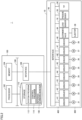
- Fig. 1 is a diagram illustrating an outline of a screw tightening system 1 according to the embodiment.
- screw tightening system 1 includes an articulated robot (hereinafter simply referred to as a "robot 10") and a robot controller 100 that controls robot 10.
- Robot 10 is an example of an "actuator”.
- Robot controller 100 is an example of a "controller”.
- a screw feeder 60 sequentially feeds a screw 50 to a predetermined position.
- Robot 10 of screw tightening system 1 picks screw 50 fed by screw feeder 60.
- Robot 10 conveys picked screw 50 to a position of a workpiece 70, and tightens screw 50 in a screw hole 72 (see Fig. 3 ) provided in the workpiece 70.
- Robot 10 includes a base 11 and a plurality of movable portions 12, 13, 14, 15, 16, and 17. Movable portions 12, 13, 14, 15, 16, and 17 correspond to joints of robot 10. Each of movable portions 12, 13, 14, 15, 16, and 17 drives a link constituting robot 10 along a rotation axis as shown in Fig. 1 .
- An end effector 18 is attached to a distal end of an arm of robot 10. Any tool distal end jig can be attached to end effector 18.
- a driver bit 20 that rotationally drives screw 50 is rotatably attached to end effector 18. Furthermore, a rotating motor 37 (see Fig. 2 ) that rotationally drives driver bit 20 and a lifting motor 38 (see Fig. 2 ) that moves driver bit 20 upward and downward are mechanically coupled to driver bit 20.
- an adsorbing sleeve 22 is provided on an outer periphery of driver bit 20. An opening 21 of adsorbing sleeve 22 is provided near a distal end of driver bit 20. Adsorbing sleeve 22 communicates with an ejector 39 (see Fig.
- a pressure sensor 28 that detects a gauge pressure of the path is provided.
- the mechanism for holding screw 50 on driver bit 20 adsorbs screw 50 by negative pressure.
- the mechanism for holding screw 50 on driver bit 20 is not limited to the configuration by adsorption (negative pressure), and a configuration using magnetic force or the like may be used.
- a load sensor 19 that detects a load generated in end effector 18 and a tool distal end jig (such as driver bit 20) is provided in a portion where end effector 18 is attached to the arm of robot 10.
- Load sensor 19 outputs a detection result indicating a magnitude of the generated load and a direction in which the load is generated.
- the detection result of load sensor 19 may be output in a form of a kind of vector.
- an operation of robot 10 will be mainly described on the basis of a coordinate system XYZ (hereinafter also referred to as a "TCP coordinate system") based on the end effector 18.
- TCP coordinate system an axial direction of driver bit 20 corresponds to a Z axis. That is, Z axis corresponds to a direction in which driver bit 20 presses screw 50.
- load sensor 19 outputs, as detection results, a load in an X-axis direction (X), a load in a Y-axis direction (Y), and a load in a Z-axis direction (Z) in the TCP coordinate system, and outputs a load (moment) in a rotational direction (RX) about an X axis, a load (moment) in a rotational direction (RY) about a Y axis, and a load (moment) in a rotational direction (RZ) about Z axis.
- X X-axis direction
- Y load in a Y-axis direction
- Z Z-axis direction
- An information processing device 200 may be connected to robot controller 100.
- Information processing device 200 is typically a general-purpose computer, and presents information from robot controller 100 to a user and gives instruction by the user to robot controller 100 in accordance with an operation by the user.
- Fig. 2 is a schematic diagram illustrating a hardware configuration example of screw tightening system 1 according to the embodiment.
- robot 10 includes motors 31, 32, 33, 34, 35, and 36 respectively associated with movable portions 12, 13 14, 15, 16, and 17, and drivers 41, 42, 43, 44, 45, and 46 respectively driving motors 31, 32, 33, 34, 35, and 36.
- motors 31, 32, 33, 34, 35, and 36 are collectively referred to as a "joint motor 300".
- drivers 41, 42, 43, 44, 45, and 46 are collectively referred to as a "driver 400".
- Robot 10 includes rotating motor 37 that rotationally drives driver bit 20 and a driver 47 that drives rotating motor 37.
- Robot 10 includes lifting motor 38 that moves driver bit 20 upward and downward and a driver 48 that drives lifting motor 38.
- Rotating motor 37 and lifting motor 38 are mechanically coupled to driver bit 20.
- Robot 10 includes ejector 39 that generates a negative pressure, and an electromagnetic valve 49 that controls on and off of generation of the negative pressure by ejector 39.
- Teaching pendant 26 performs teaching or the like of robot 10 in response to the operation by the user. Teaching pendant 26 may be configured to be detachable from robot 10.
- Robot controller 100 is a type of computer, and includes a processor 102, a memory 104, an interface 106, and a storage 110 as main hardware components. These components are connected via a bus 108.
- Processor 102 includes typically a central processing unit (CPU), a micro-processing unit (MPU), or the like.
- Memory 104 typically includes a volatile storage device such as a dynamic random access memory (DRAM) or a static random access memory (SRAM).
- Storage 110 typically includes a non-volatile storage device such as a solid state disk (SSD) or a flash memory.
- Storage 110 stores a system program 112 for performing basic processing and a control program 114.
- Control program 114 includes computer-readable instructions for controlling robot 10.
- Processor 102 reads system program 112 and control program 114 stored in storage 110, develops system program 112 and control program 114 in memory 104, and executes system program 112 and control program 114 to perform processing for controlling robot 10 as described later.
- Interface 106 is responsible for exchanging signals and/or data between robot controller 100 and robot 10.
- commands for controlling drivers 41, 42, 43, 44, 45, 46, 47, and 48 and electromagnetic valve 49 are transmitted from robot controller 100 to robot 10, and respective detection results by load sensor 19 and pressure sensor 28 are transmitted from robot 10 to robot controller 100.
- driver 47 calculates a torque value of a torque generated in rotating motor 37. The torque value calculated by driver 47 is transmitted from robot 10 to robot controller 100.
- FIG. 2 illustrates the configuration example in which necessary processing is provided by processor 102 executing the programs
- some or all of the provided processing may be implemented by using a dedicated hardware circuit (for example, an application specific integrated circuit (ASIC), a field-programmable gate array (FPGA), or the like).
- ASIC application specific integrated circuit
- FPGA field-programmable gate array
- Fig. 2 illustrates an example in which robot controller 100 is configured independently of robot 10, some or all of the functions and processing provided by robot controller 100 may be incorporated in robot 10.
- robot controller 100 may be mounted as a controller dedicated to robot control, or may be implemented by using a general-purpose programmable logic controller (PLC) or a personal computer.
- PLC general-purpose programmable logic controller
- robot controller 100 may be achieved by using computing resources on a network referred to as a so-called cloud.
- the “actuator” may be a screw tightening device including driver bit 20, rotating motor 37, driver 47, lifting motor 38, and driver 48.
- screw tightening system 1 may be implemented in any manner.
- Fig. 3 is a diagram illustrating an example of shapes of the screw and the screw hole.
- the screw 50 includes a head 51 and a screw portion 53.
- Head 51 is provided with a hole 52 into which driver bit 20 is inserted. Head 51 prevents screw 50 from being excessively screwed into screw hole 72.
- Screw portion 53 includes a plurality of ridges and a plurality of grooves.
- Screw hole 72 provided in workpiece 70 also includes a plurality of ridges and a plurality of grooves. Screw 50 is rotated by a torque applied from driver bit 20.
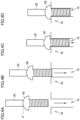
- Figs. 4A to 4D are diagrams illustrating an example of the screw tightening operation by screw tightening system 1.
- Fig. 4A is a diagram illustrating a state in which driver bit 20 is located at a screw tightening start position P.
- Screw tightening start position P is a position at which driver bit 20 starts the screw tightening operation, that is, a position at which the rotation of screw 50 is started.
- Robot controller 100 controls joint motor 300 and lifting motor 38 so that driver bit 20 reaches screw tightening start position P.
- driver bit 20 picks screw 50 from screw feeder 60 (see Fig. 1 ), and moves to screw tightening start position P while holding screw 50.
- robot controller 100 controls rotating motor 37 and lifting motor 38 so that driver bit 20 rotates and descends under a rotation condition and a descent condition for a preparation period.
- the preparation period is a period from when the rotation of driver bit 20 starts until when screw 50 and screw hole 72 engage with each other for the first time.
- Fig. 4B is a diagram illustrating a state in which screw 50 and screw hole 72 engage with each other for the first time.
- the preparation period ends and a temporary tightening period starts.
- the temporary tightening period is a period from when screw 50 engages with screw hole 72 provided in workpiece 70 until when screw 50 is seated in screw hole 72.
- robot controller 100 controls rotating motor 37 and lifting motor 38 so that driver bit 20 rotates and descends under a rotation condition and a descent condition for the temporary tightening period. Specifically, in the temporary tightening period, robot controller 100 controls rotating motor 37 and lifting motor 38 so that driver bit 20 rotates at high speed with a torque smaller than a torque in a full tightening period described later. As a result, screw 50 is temporarily tightened in screw hole 72.
- Fig. 4C is a diagram illustrating a state in which screw 50 is seated in screw hole 72.
- the temporary tightening period ends and the full tightening period starts.
- robot controller 100 controls rotating motor 37 and lifting motor 38 so that driver bit 20 rotates and descends under a rotation condition and a descent condition for the full tightening period.
- robot controller 100 controls rotating motor 37 and lifting motor 38 so that driver bit 20 rotates slowly with a torque greater than the torque in the temporary tightening period.
- screw 50 is fully tightened in screw hole 72.
- Fig. 4D is a diagram illustrating a state in which screw 50 is fully tightened in screw hole 72.
- robot controller 100 controls rotating motor 37 and lifting motor 38 to stop the rotation and descent of driver bit 20. Accordingly, the rotation and descent of driver bit 20 stop, and as a result, the rotation and descent of screw 50 also stop.
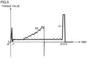
- Fig. 5 is a diagram illustrating an example of transition of the torque value when the screw tightening operation is normal and an example of transition of the torque value when the screw tightening operation is abnormal.
- a horizontal axis indicates an elapsed time from the start of the screw tightening operation. That is, the horizontal axis indicates an elapsed time from the start of rotation of driver bit 20 that has reached screw tightening start position P.
- a vertical axis indicates the torque value of the torque generated in rotating motor 37.
- a thick line (line N) indicates an example of transition of the torque value when the screw tightening operation is normal.
- a thin line (line AN) indicates an example of transition of the torque value when the screw tightening operation is abnormal.
- Timing t0 to t1 indicate the preparation period.
- Timing t1 to t2 indicate the temporary tightening period.
- Timing t2 to t3 indicate the full tightening period.
- Timing t3 to t4 is a period in which the torque applied to screw 50 is released.
- screw 50 rotates at high speed. Therefore, time for the screw tightening operation is reduced.
- screw 50 and screw hole 72 do not engage with each other, and there is a high possibility that the screw tightening fails. That is, in the temporary tightening period, there is a high possibility that screw 50 is obliquely tightened or screw 50 is burned on workpiece 70.
- screw 50 and workpiece 70 can be damaged. Therefore, more reliable detection of a screw tightening abnormality in the temporary tightening period is a problem in automation of screw tightening operation.
- the torque value of the torque acting on screw 50 depends on a size and material of screw 50, a tightening torque and rotation speed of driver bit 20, and a type and movement speed of robot 10. Therefore, in a method of comparing the torque value of the torque acting on screw 50 with a threshold value, it is necessary to change the threshold value or set the threshold value to a higher value in accordance with the size and material of screw 50, the tightening torque and rotation speed of driver bit 20, and the type and movement speed of robot 10.
- the threshold value is set high, there is a problem that the detection of a screw tightening abnormality is delayed.
- screw tightening system 1 has a structure capable of more reliably detecting a screw tightening abnormality.
- Fig. 6 is a diagram for describing an outline of the processing of detecting a screw tightening abnormality by screw tightening system 1 according to the embodiment.
- a commander 150, an acquirer 151, a calculator 152, and a determiner 153 are implemented by processor 102 executing system program 112 and control program 114.
- Commander 150 outputs a drive command and a stop command of rotating motor 37 to driver 47.
- Driver 47 controls driving of rotating motor 37 in response to the command received from commander 150.
- driver bit 20 rotates or stops.
- commander 150 may be configured not to output a drive command to driver 47 instead of outputting a stop command to driver 47.
- Commander 150 outputs a drive command and a stop command of lifting motor 38 to driver 48.
- Driver 48 controls driving of lifting motor 38 in response to the command received from commander 150.
- driver bit 20 ascends or descends.
- commander 150 may be configured not to output a drive command to driver 48 instead of outputting a stop command to driver 48.
- Commander 150 outputs a drive command and a stop command of joint motor 300 to driver 400.
- Driver 400 controls driving of joint motor 300 in response to the command received from commander 150.
- driver bit 20 moves back and forth between above screw feeder 60 and above workpiece 70.
- commander 150 may be configured not to output a drive command to driver 400 instead of outputting a stop command to driver 400.
- Commander 150 outputs a current status in the screw tightening operation to driver 47, driver 48, driver 400, acquirer 151, calculator 152, and determiner 153.
- the current status in the screw tightening operation includes the preparation period, the temporary tightening period, and the full tightening period.
- acquirer 151 acquires torque values tq of the torque generated in rotating motor 37 from driver 47.
- the torque value(s) of the torque generated in rotating motor 37 is(are) also simply referred to as "torque value(s) tq".
- Driver 47 calculates torque value tq.
- Acquirer 151 preferably acquires torque value tq at a predetermined cycle.
- Acquirer 151 may acquire torque value tq from driver 47 from the start of the screw tightening operation.
- Calculator 152 calculates standard deviation sd of torque values tq acquired by acquirer 151 in the temporary tightening period.
- calculator 152 preferably starts calculating standard deviation sd of torque values tq.
- calculator 152 starts calculating standard deviation sd of torque values tq.
- calculator 152 calculates standard deviation sd by using torque values tq acquired for all the number of times by acquirer 151 from the start of the temporary tightening period to the present time. For example, when torque value tq is acquired 110 times by acquirer 151 from the start of the temporary tightening period to the present time, calculator 152 calculates standard deviation sd by using torque values tq for the 110 times.
- calculator 152 may calculate standard deviation sd by using torque values tq for the latest second predetermined number of times acquired by acquirer 151. For example, when torque value tq is acquired 110 times by acquirer 151 from the start of the temporary tightening period to the present time, calculator 152 calculates the standard deviation by using torque values tq for the latest 100 times. Note that the first predetermined number of times and the second predetermined number of times may be the same or different.
- Determiner 153 calculates a ratio of standard deviation sd calculated by calculator 152 to a reference standard deviation 160. When the ratio of standard deviation sd calculated by calculator 152 to reference standard deviation 160 exceeds a first threshold value, determiner 153 determines that there is an abnormality.
- determiner 153 determines that there is an abnormality when the following Formula 1 is satisfied. sd / Ref > TH "sd" in Formula 1 represents the standard deviation calculated by calculator 152, “Ref' in Formula 1 represents reference standard deviation 160, and "TH” in Formula 1 represents the first threshold value.
- Reference standard deviation 160 is stored in storage 110. Reference standard deviation 160 is calculated on the basis of torque values tq acquired by acquirer 151 in the temporary tightening period when screw 50 is considered to be normally tightened to screw hole 72. In the following description, the temporary tightening period when screw 50 is considered to be normally tightened to screw hole 72 is also referred to as a "normal temporary tightening period".
- reference standard deviation 160 may be a standard deviation of torque values tq acquired for all the number of times in the normal temporary tightening period.
- reference standard deviation 160 may be an average value of standard deviations each of which is calculated based on the torque values tq acquired for a third predetermined number of times by acquirer 151 in the normal temporary tightening period.
- determiner 153 When determining that there is an abnormality, determiner 153 outputs a determination result to commander 150.
- commander 150 When receiving the determination result from determiner 153, commander 150 outputs a stop command of rotating motor 37 to driver 47 to stop the rotation of driver bit 20.
- commander 150 When receiving the determination result from determiner 153, commander 150 outputs a stop command of lifting motor 38 to driver 48 to stop the descent of driver bit 20.
- the driving of rotating motor 37 and lifting motor 38 is stopped, and thus, the rotation and the descent of driver bit 20 are stopped. Then, the rotation and the descent of screw 50 are also stopped.
- commander 150 outputs a drive command of lifting motor 38 to driver 48 so that driver bit 20 releases screw 50 and ascends.
- driver bit 20 releases screw 50 and ascends to a predetermined position. The user then removes screw 50 from screw hole 72.
- robot 10 may remove screw 50 from screw hole 72.
- commander 150 outputs a drive command of rotating motor 37 to driver 47 and outputs a drive command of lifting motor 38 to driver 48 so that driver bit 20 ascends while holding screw 50 and reversely rotating. As a result, screw 50 is removed from screw hole 72.
- commander 150 may command driver 47, driver 48, and driver 400 to resume the screw tightening operation or redo the screw tightening operation.
- commander 150 may output the determination result to information processing device 200.
- information processing device 200 may notify that the screw tightening abnormality has occurred.
- a notification method in a case where information processing device 200 includes a display, the occurrence of the screw tightening abnormality may be displayed on the display.
- the notification method in a case where information processing device 200 includes a speaker, the occurrence of the screw tightening abnormality may be notified by outputting a sound from the speaker.
- the sound output from the speaker may be a notification sound or a voice.
- determiner 153 selects one from the plurality of reference standard deviations prepared in advance depending on at least one of the size of screw 50, the material of screw 50, and the material of screw hole 72.
- the size of screw 50 includes at least one of a size of a diameter of head 51 (see Fig. 3 ) and a length of screw portion 53 (see Fig. 3 ).
- the material of screw 50 is, for example, iron, stainless steel, aluminum, resin, or the like.
- the material of screw hole 72 is, for example, iron, stainless steel, aluminum, resin, or the like.
- determiner 153 selects one from the plurality of first threshold values prepared in advance depending on at least one of the size of screw 50, the material of screw 50, and the material of screw hole 72.
- FIGs. 7 and 8 are flowcharts illustrating a procedure of processing for screw tightening executed by screw tightening system 1 according to the embodiment.
- Figs. 7 and 8 illustrate a part of a control method for controlling robot 10. Each step shown in Figs. 7 and 8 is typically implemented by processor 102 of robot controller 100 executing control program 114. As a result, a command is given from robot controller 100 to robot 10, and thus the processing shown in Figs. 7 and 8 is implemented.
- step S1 robot controller 100 controls joint motor 300 and lifting motor 38 to arrange driver bit 20 at screw tightening start position P.
- step S2 robot controller 100 controls rotating motor 37 and lifting motor 38 to rotate and descend driver bit 20 under the rotation condition and the descent condition for the preparation period.
- step S3 robot controller 100 determines whether a start condition of the temporary tightening period is satisfied. Robot controller 100 determines that the start condition of the temporary tightening period is satisfied on the basis of the elapsed time from the start of the rotation of driver bit 20. When torque value tq is acquired from the start of the screw tightening operation, robot controller 100 may determine that the start condition of the temporary tightening period is satisfied on the basis of a change in torque value tq. When determining that the start condition of the temporary tightening period is satisfied (YES in step S3), robot controller 100 advances the processing to step S4.
- step S4 robot controller 100 controls rotating motor 37 and lifting motor 38 to rotate and descend driver bit 20 under the rotation condition and the descent condition for the temporary tightening period.
- step S5 robot controller 100 acquires torque value tq.
- step S6 robot controller 100 determines whether an end condition of the temporary tightening period is satisfied. As an example, robot controller 100 determines that the end condition of the temporary tightening period is satisfied on the basis of the elapsed time from the start of the rotation of driver bit 20. When determining that the end condition of the temporary tightening period is satisfied (YES in step S6), robot controller 100 advances the processing to step S13. On the other hand, when determining that the end condition of the temporary tightening period is not satisfied (NO in step S6), robot controller 100 advances the processing to step S7.
- step S7 robot controller 100 determines whether torque value tq has been acquired the first predetermined number of times or more.
- robot controller 100 advances the processing to step S8.
- robot controller 100 returns the processing to step S5.
- step S8 robot controller 100 calculates standard deviation sd of torque values tq.
- step S9 robot controller 100 determines whether the ratio of standard deviation sd calculated in step S8 to reference standard deviation 160 exceeds the first threshold value.
- robot controller 100 advances the processing to step S10.
- robot controller 100 advances the processing to step S12.
- step S10 robot controller 100 controls rotating motor 37 and lifting motor 38 to stop the rotation and the descent of driver bit 20.
- step S11 robot controller 100 notifies the screw tightening abnormality.
- robot controller 100 commands information processing device 200 to notify the screw tightening abnormality.
- information processing device 200 notifies that the screw tightening abnormality has occurred.
- step S12 robot controller 100 determines whether an end condition of the temporary tightening period is satisfied.
- the processing of step S12 is similar to the processing of step S6.
- robot controller 100 advances the processing to step S13.
- robot controller 100 returns the processing to step S5.
- step S13 robot controller 100 controls rotating motor 37 and lifting motor 38 to rotate and descend driver bit 20 under the rotation condition and the descent condition for the full tightening period.
- step S14 robot controller 100 determines whether an end condition of the full tightening period is satisfied. As an example, robot controller 100 determines that the end condition of the full tightening period is satisfied on the basis of an elapsed time from the end of the temporary tightening period. When determining that the end condition of the full tightening period is satisfied (YES in step S14), robot controller 100 advances the processing to step S 15.
- step S15 robot controller 100 controls rotating motor 37 and lifting motor 38 to stop the rotation and the descent of driver bit 20.
- step S16 robot controller 100 controls lifting motor 38 to ascend driver bit 20 to a predetermined position.
- step S11 or S16 the processing for screw tightening ends.
- step S11 the user may remove screw 50 from screw hole 72, or robot 10 may remove screw 50 from screw hole 72. After screw 50 is removed from screw hole 72, robot 10 may resume the screw tightening operation or redo the screw tightening operation from the beginning in accordance with the control of robot controller 100.
- screw tightening system 1 determines whether an abnormality has occurred by the ratio of standard deviation sd of torque values tq in the temporary tightening period to reference standard deviation 160. That is, variation in torque value tq in the temporary tightening period is relatively evaluated.
- screw tightening system 1 since there is no need to worry about the size and material of screw 50, the tightening torque and rotation speed of driver bit 20, individual differences of other equipment, and the like in setting of the threshold value, there is no need to set the threshold value high. Therefore, screw tightening system 1 according to the embodiment can detect the screw tightening abnormality more reliably in the temporary tightening period.
- reference standard deviation 160 and the first threshold value can be fixed values without depending on the size of screw 50, the material of the screw 50, and the material of screw hole 72. Therefore, screw tightening system 1 according to the embodiment can reduce time and effort required for measuring reference standard deviation 160 and adjusting the first threshold value.
- screw tightening system 1 may be configured such that the user can change the first threshold value.
- information processing device 200 receives an operation of changing the first threshold value and transmits a command corresponding to the received operation of changing to robot controller 100.
- Robot controller 100 changes the first threshold value in response to the command.
- the user can optimize the detection of a screw tightening abnormality by adjusting the first threshold value.
- the user preferably adjusts the first threshold value on the basis of the standard deviation of torque values tq of the torque generated in rotating motor 37 in the temporary tightening period when screw 50 is considered not to be normally tightened to screw hole 72.
- determiner 153 may also determine that there is an abnormality when the load in Z-axis direction (direction Z shown in Fig. 1 ) detected by load sensor 19 exceeds the second threshold value.
- Fig. 9 is a flowchart illustrating a modification of the procedure of the processing for screw tightening executed by screw tightening system 1 according to the embodiment.
- the processing of step S11A is added to the flowcharts of Figs. 7 and 8 .
- processing similar to the processing shown in Figs. 7 and 8 are denoted by the same step numbers, and the description thereof will not be repeated.
- step S9 When determining in step S9 that the ratio of standard deviation sd calculated in step S8 to reference standard deviation 160 does not exceed the first threshold value (NO in step S9), robot controller 100 advances the processing to step S11A.
- step S11A robot controller 100 determines whether the load in Z-axis direction detected by load sensor 19 exceeds the second threshold value.
- robot controller 100 advances the processing to step S10.
- robot controller 100 advances the processing to step S12.
- the screw tightening system 1 according to the modification determines that there is an abnormality when the ratio of standard deviation sd of the torque generated in rotating motor 37 in the temporary tightening period to reference standard deviation 160 exceeds the first threshold value. Therefore, as in the embodiment, screw tightening system 1 according to the modification can detect the screw tightening abnormality more reliably in the temporary tightening period.
- screw tightening system 1 according to the modification also determines that there is an abnormality when the load in Z-axis direction detected by load sensor 19 exceeds the second threshold value.
- a load in Z-axis direction exceeding the second threshold value is generated in driver bit 20, it is considered that a screw tightening abnormality has occurred. Therefore, screw tightening system 1 according to the modification performs not only the determination based on standard deviation sd of the torque generated in rotating motor 37 in the temporary tightening period but also the determination based on the load in Z-axis direction generated in driver bit 20.
- accuracy of the detection of a screw tightening abnormality is enhanced.
- the above embodiment includes the following technical ideas.
- a screw tightening system including:
- controller (100) further includes a commander (150) that commands the motor (37) to stop when it is determined that there is an abnormality.
- the screw tightening system according to configuration 3, in which the calculator (152) calculates the standard deviation by using the torque values acquired for all number of times from a start of the temporary tightening period to a present time.
- the screw tightening system according to any one of configurations 1 to 5, in which the reference standard deviation is an average value of standard deviations each of which is calculated based on the torque values acquired for a third predetermined number of times in the temporary tightening period when the screw (50) is considered to be normally tightened to the screw hole (72).
- the screw tightening system according to any one of configurations 1 to 7, in which the determiner (153) selects one from a plurality of reference standard deviations prepared in advance depending on at least one of a size of the screw (50), a material of the screw (50), and a material of the screw hole (72).
- the screw tightening system according to any one of configurations 1 to 8, in which the determiner (153) selects one from a plurality of first threshold values prepared in advance depending on at least one of the size of the screw (50), the material of the screw (50), and the material of the screw hole (72).
- a controller (100) configured to control an actuator (10) including a driver bit (20) configured to rotationally drive a screw (50) and a motor (37) coupled with the driver bit (20), the controller (100) including:
- the embodiment can more reliably detect a screw tightening abnormality in the operation of tightening a screw to a workpiece or the like by using a robot or a screw tightening device. It is therefore possible to reduce breakage of the screw or the workpiece due to failure in tightening the screw. In addition, when the screw tightening abnormality is detected, the tightening can be more reliably achieved by redoing the screw tightening operation.
Landscapes
- Engineering & Computer Science (AREA)
- Mechanical Engineering (AREA)
- Robotics (AREA)
- Physics & Mathematics (AREA)
- General Physics & Mathematics (AREA)
- Automation & Control Theory (AREA)
- Details Of Spanners, Wrenches, And Screw Drivers And Accessories (AREA)
Abstract
A screw tightening system (1) includes an actuator (10) including a driver bit (20) that rotationally drives a screw and a motor coupled with driver bit (20), and a controller (100) that controls actuator (10). Controller (100) includes an acquirer that acquires torque values of a torque generated in a motor, a calculator that calculates a standard deviation of the torque values in a temporary tightening period, and a determiner that determines that there is an abnormality when a ratio of the standard deviation to a reference standard deviation exceeds a first threshold value.
Description
- The present invention relates to a screw tightening system, a controller, and a control program.
- A technique for automating a screw tightening operation by using a screw tightening device is known. For example,
Japanese Patent Laying-Open No. 2020-163500 - The screw tightening device disclosed in
Japanese Patent Laying-Open No. 2020-163500 - The present invention provides a solution capable of more reliably detecting a screw tightening abnormality in a temporary tightening period from when a screw engages with a screw hole until when the screw is seated in the screw hole.
- A screw tightening system according to an aspect of the present invention includes an actuator including a driver bit configured to rotationally drive a screw and a motor coupled with the driver bit, and a controller configured to control the actuator. The controller includes an acquirer configured to acquire torque values of a torque generated in the motor, a calculator configured to calculate a standard deviation of the torque values acquired in a temporary tightening period from when the screw engages with a screw hole until when the screw is seated in the screw hole, and a determiner configured to determine that there is an abnormality when a ratio of the standard deviation to a reference standard deviation exceeds a first threshold value.
- This configuration determines whether an abnormality has occurred by the ratio of the standard deviation d of the torque value in the temporary tightening period to the reference standard deviation. That is, variation in the torque value in the temporary tightening period is relatively evaluated. Thus, since there is no need to worry about the size and material of the screw, the tightening torque and rotation speed of the driver bit, and individual differences of other equipment in setting of the threshold value, there is no need to set the threshold value high. Therefore, this configuration can detect the screw tightening abnormality more reliably in the temporary tightening period.
- The controller may further include a commander that commands the motor to stop when it is determined that there is an abnormality. In this configuration, since the screw tightening operation is stopped when it is determined that there is an abnormality, it is possible to suppress breakage of the screw or the screw hole.
- The acquirer may acquire each of the torque values at a predetermined cycle, and the calculator may start calculation of the standard deviation when the torque value is acquired a first predetermined number of times or more in the temporary tightening period. This configuration enhances reliability of the standard deviation calculated by the calculator, and thus enhances accuracy of the detection of the screw tightening abnormality.
- The calculator may calculate the standard deviation by using the torque values acquired for all number of times from a start of the temporary tightening period to a present time. This configuration enhances the reliability of the standard deviation calculated by the calculator, and thus enhances the accuracy of the detection of the screw tightening abnormality.
- The calculator may calculate the standard deviation by using the torque values for a latest second predetermined number of times. This configuration enhances the reliability of the standard deviation calculated by the calculator, and thus enhances the accuracy of the detection of the screw tightening abnormality.
- The reference standard deviation may be calculated based on the torque values acquired for all number of times in the temporary tightening period when the screw is considered to be normally tightened to the screw hole. This configuration enhances the reliability of the reference standard deviation.
- The reference standard deviation may be an average value of standard deviations each of which is calculated based on the torque values acquired for a third predetermined number of times in the temporary tightening period when the screw is considered to be normally tightened to the screw hole. This configuration enhances the reliability of the reference standard deviation.
- The determiner may select one from a plurality of reference standard deviations prepared in advance depending on at least one of a size of the screw, a material of the screw, and a material of the screw hole. This configuration enhances the reliability of the reference standard deviation.
- The determiner may select one from a plurality of first threshold values prepared in advance depending on at least one of the size of the screw, the material of the screw, and the material of the screw hole. This configuration enhances the accuracy of the detection of the screw tightening abnormality.
- The actuator may further include a load sensor configured to detect a load generated in the driver bit, and the determiner may determine that there is an abnormality when the load detected by the load sensor exceeds a second threshold value. This configuration enhances the accuracy of the detection of the screw tightening abnormality.
- A controller according to another aspect of the present invention controls an actuator including a driver bit configured to rotationally drive a screw and a motor coupled with the driver bit. The controller includes an acquirer configured to acquire torque values of a torque generated in the motor, a calculator configured to calculate a standard deviation of the torque values acquired in a temporary tightening period from when the screw engages with a screw hole until when the screw is seated in the screw hole, and a determiner configured to determine that there is an abnormality when a ratio of the standard deviation to a reference standard deviation exceeds a first threshold value.
- This configuration determines whether an abnormality has occurred by the ratio of the standard deviation of the torque value in the temporary tightening period to the reference standard deviation. That is, variation in the torque value in the temporary tightening period is relatively evaluated. Thus, since there is no need to worry about the size and material of the screw, the tightening torque and rotation speed of the driver bit, and individual differences of other equipment in setting of the threshold value, there is no need to set the threshold value high. Therefore, this configuration can detect the screw tightening abnormality more reliably in the temporary tightening period.
- A control program according to another aspect of the present invention is executed by a computer connected to an actuator including a driver bit configured to rotationally drive a screw and a motor coupled with the driver bit. The control program causes the computer to acquire torque values of a torque generated in the motor, calculate a standard deviation of the torque values acquired in a temporary tightening period from when the screw engages with a screw hole until when the screw is seated in the screw hole, and determine that there is an abnormality when a ratio of the standard deviation to a reference standard deviation exceeds a first threshold value.
- This configuration determines whether an abnormality has occurred by the ratio of the standard deviation of the torque value in the temporary tightening period to the reference standard deviation. That is, variation in the torque value in the temporary tightening period is relatively evaluated. Thus, since there is no need to worry about the size and material of the screw, the tightening torque and rotation speed of the driver bit, and individual differences of other equipment in setting of the threshold value, there is no need to set the threshold value high. Therefore, this configuration can detect the screw tightening abnormality more reliably in the temporary tightening period.
- The above and other objects, features, aspects and advantages of the present invention will become apparent from the following detailed description of the present invention to be understood in conjunction with the accompanying drawings.
-
-
Fig. 1 is a diagram illustrating an outline of ascrew tightening system 1 according to an embodiment. -
Fig. 2 is a schematic diagram illustrating a hardware configuration example ofscrew tightening system 1 according to the embodiment. -
Fig. 3 is a diagram illustrating an example of shapes of a screw and a screw hole. -
Figs. 4A to 4D are diagrams illustrating an example of a screw tightening operation byscrew tightening system 1. -
Fig. 5 is a diagram illustrating an example of transition of a torque value when the screw tightening operation is normal and an example of transition of a torque value when the screw tightening operation is abnormal. -
Fig. 6 is a diagram for describing an outline of processing of detecting a screw tightening abnormality byscrew tightening system 1 according to the embodiment. -
Figs. 7 and8 are flowcharts illustrating a procedure of processing for screw tightening executed byscrew tightening system 1 according to the embodiment. -
Fig. 9 is a flowchart illustrating a modification of the procedure of the processing for screw tightening executed byscrew tightening system 1 according to the embodiment. - Hereinafter, an embodiment of the present invention will be described with reference to the drawings. The same or corresponding parts in the drawings are denoted by the same reference signs, and the description thereof will not be repeated.
- First, an example of a situation to which the present invention is applied will be described.
-
Fig. 1 is a diagram illustrating an outline of ascrew tightening system 1 according to the embodiment. Referring toFig. 1 ,screw tightening system 1 includes an articulated robot (hereinafter simply referred to as a "robot 10") and arobot controller 100 that controlsrobot 10.Robot 10 is an example of an "actuator".Robot controller 100 is an example of a "controller". - In
screw tightening system 1, ascrew feeder 60 sequentially feeds ascrew 50 to a predetermined position.Robot 10 ofscrew tightening system 1 picks screw 50 fed byscrew feeder 60.Robot 10 conveys pickedscrew 50 to a position of aworkpiece 70, and tightensscrew 50 in a screw hole 72 (seeFig. 3 ) provided in theworkpiece 70. -
Robot 10 includes abase 11 and a plurality ofmovable portions Movable portions robot 10. Each ofmovable portions link constituting robot 10 along a rotation axis as shown inFig. 1 . Anend effector 18 is attached to a distal end of an arm ofrobot 10. Any tool distal end jig can be attached to endeffector 18. - In a configuration example shown in
Fig. 1 , adriver bit 20 that rotationally drivesscrew 50 is rotatably attached to endeffector 18. Furthermore, a rotating motor 37 (seeFig. 2 ) that rotationally drivesdriver bit 20 and a lifting motor 38 (seeFig. 2 ) that movesdriver bit 20 upward and downward are mechanically coupled todriver bit 20. As an example of a mechanism fordriver bit 20 to holdscrew 50, an adsorbingsleeve 22 is provided on an outer periphery ofdriver bit 20. Anopening 21 of adsorbingsleeve 22 is provided near a distal end ofdriver bit 20.Adsorbing sleeve 22 communicates with an ejector 39 (seeFig. 2 ), and adsorbsscrew 50 by a negative pressure generated byejector 39. On a path fromejector 39 to adsorbingsleeve 22, a pressure sensor 28 (seeFig. 2 ) that detects a gauge pressure of the path is provided. - The mechanism for holding
screw 50 ondriver bit 20 adsorbs screw 50 by negative pressure. However, the mechanism for holdingscrew 50 ondriver bit 20 is not limited to the configuration by adsorption (negative pressure), and a configuration using magnetic force or the like may be used. - A
load sensor 19 that detects a load generated inend effector 18 and a tool distal end jig (such as driver bit 20) is provided in a portion whereend effector 18 is attached to the arm ofrobot 10.Load sensor 19 outputs a detection result indicating a magnitude of the generated load and a direction in which the load is generated. The detection result ofload sensor 19 may be output in a form of a kind of vector. - In the following description, an operation of
robot 10 will be mainly described on the basis of a coordinate system XYZ (hereinafter also referred to as a "TCP coordinate system") based on theend effector 18. In the TCP coordinate system, an axial direction ofdriver bit 20 corresponds to a Z axis. That is, Z axis corresponds to a direction in which driver bit 20 presses screw 50. - Specifically,
load sensor 19 outputs, as detection results, a load in an X-axis direction (X), a load in a Y-axis direction (Y), and a load in a Z-axis direction (Z) in the TCP coordinate system, and outputs a load (moment) in a rotational direction (RX) about an X axis, a load (moment) in a rotational direction (RY) about a Y axis, and a load (moment) in a rotational direction (RZ) about Z axis. - An
information processing device 200 may be connected torobot controller 100.Information processing device 200 is typically a general-purpose computer, and presents information fromrobot controller 100 to a user and gives instruction by the user torobot controller 100 in accordance with an operation by the user. -
Fig. 2 is a schematic diagram illustrating a hardware configuration example ofscrew tightening system 1 according to the embodiment. Referring toFig. 2 ,robot 10 includesmotors movable portions drivers motors motors joint motor 300". In addition,drivers driver 400". -
Robot 10 includesrotating motor 37 that rotationally drivesdriver bit 20 and adriver 47 that drivesrotating motor 37.Robot 10 includes liftingmotor 38 that movesdriver bit 20 upward and downward and adriver 48 that drives liftingmotor 38. Rotatingmotor 37 and liftingmotor 38 are mechanically coupled todriver bit 20. -
Robot 10 includesejector 39 that generates a negative pressure, and anelectromagnetic valve 49 that controls on and off of generation of the negative pressure byejector 39. -
Drivers electromagnetic valve 49,load sensor 19,pressure sensor 28, and ateaching pendant 26 are electrically connected torobot controller 100 via aninterface 40.Teaching pendant 26 performs teaching or the like ofrobot 10 in response to the operation by the user.Teaching pendant 26 may be configured to be detachable fromrobot 10. -
Robot controller 100 is a type of computer, and includes aprocessor 102, amemory 104, aninterface 106, and astorage 110 as main hardware components. These components are connected via abus 108. -
Processor 102 includes typically a central processing unit (CPU), a micro-processing unit (MPU), or the like.Memory 104 typically includes a volatile storage device such as a dynamic random access memory (DRAM) or a static random access memory (SRAM).Storage 110 typically includes a non-volatile storage device such as a solid state disk (SSD) or a flash memory.Storage 110 stores asystem program 112 for performing basic processing and acontrol program 114.Control program 114 includes computer-readable instructions for controllingrobot 10.Processor 102 readssystem program 112 andcontrol program 114 stored instorage 110, developssystem program 112 andcontrol program 114 inmemory 104, and executessystem program 112 andcontrol program 114 to perform processing for controllingrobot 10 as described later. -
Interface 106 is responsible for exchanging signals and/or data betweenrobot controller 100 androbot 10. Inscrew tightening system 1, commands for controllingdrivers electromagnetic valve 49 are transmitted fromrobot controller 100 torobot 10, and respective detection results byload sensor 19 andpressure sensor 28 are transmitted fromrobot 10 torobot controller 100. Inscrew tightening system 1,driver 47 calculates a torque value of a torque generated inrotating motor 37. The torque value calculated bydriver 47 is transmitted fromrobot 10 torobot controller 100. - Although
Fig. 2 illustrates the configuration example in which necessary processing is provided byprocessor 102 executing the programs, some or all of the provided processing may be implemented by using a dedicated hardware circuit (for example, an application specific integrated circuit (ASIC), a field-programmable gate array (FPGA), or the like). - Although
Fig. 2 illustrates an example in whichrobot controller 100 is configured independently ofrobot 10, some or all of the functions and processing provided byrobot controller 100 may be incorporated inrobot 10. In this case,robot controller 100 may be mounted as a controller dedicated to robot control, or may be implemented by using a general-purpose programmable logic controller (PLC) or a personal computer. - Furthermore, some or all of the functions and processing provided by
robot controller 100 may be achieved by using computing resources on a network referred to as a so-called cloud. - When a vertical articulated robot is used as the actuator, the robot ascends and descends
driver bit 20, and thus liftingmotor 38 anddriver 48 described above are unnecessary. On the other hand, when the vertical articulated robot is not used as the actuator, liftingmotor 38 anddriver 48 are necessary as described above. - In addition, the
configuration including robot 10 has been described as an example of the "actuator", but the "actuator" is not required to includerobot 10. The "actuator" may be a screw tightening device includingdriver bit 20, rotatingmotor 37,driver 47, liftingmotor 38, anddriver 48. - As described above,
screw tightening system 1 according to the embodiment may be implemented in any manner. - Next, with reference to
Figs. 3 and4 , a screw tightening operation byscrew tightening system 1 according to the embodiment will be described. -
Fig. 3 is a diagram illustrating an example of shapes of the screw and the screw hole. Referring toFig. 3 , thescrew 50 includes ahead 51 and ascrew portion 53.Head 51 is provided with ahole 52 into whichdriver bit 20 is inserted.Head 51 preventsscrew 50 from being excessively screwed intoscrew hole 72.Screw portion 53 includes a plurality of ridges and a plurality of grooves.Screw hole 72 provided inworkpiece 70 also includes a plurality of ridges and a plurality of grooves.Screw 50 is rotated by a torque applied fromdriver bit 20. Asscrew 50 descends inscrew hole 72 while rotating, the ridges ofscrew portion 53 engages with the ridges ofscrew hole 72, and the grooves ofscrew portion 53 engages with the grooves ofscrew hole 72. As a result, screw 50 andscrew hole 72 engage with each other. -
Figs. 4A to 4D are diagrams illustrating an example of the screw tightening operation byscrew tightening system 1.Fig. 4A is a diagram illustrating a state in whichdriver bit 20 is located at a screw tightening start position P. Screw tightening start position P is a position at which driver bit 20 starts the screw tightening operation, that is, a position at which the rotation ofscrew 50 is started.Robot controller 100 controlsjoint motor 300 and liftingmotor 38 so thatdriver bit 20 reaches screw tightening start position P. As a result,driver bit 20 picks screw 50 from screw feeder 60 (seeFig. 1 ), and moves to screw tightening start position P while holdingscrew 50. - When
driver bit 20 reaches screw tightening start position P,robot controller 100controls rotating motor 37 and liftingmotor 38 so thatdriver bit 20 rotates and descends under a rotation condition and a descent condition for a preparation period. As a result, screw 50 descends towardscrew hole 72 while rotating. In the embodiment, the preparation period is a period from when the rotation ofdriver bit 20 starts until whenscrew 50 andscrew hole 72 engage with each other for the first time. -
Fig. 4B is a diagram illustrating a state in which screw 50 andscrew hole 72 engage with each other for the first time. Whenscrew 50 andscrew hole 72 engage with each other for the first time, the preparation period ends and a temporary tightening period starts. In the embodiment, the temporary tightening period is a period from whenscrew 50 engages withscrew hole 72 provided inworkpiece 70 until whenscrew 50 is seated inscrew hole 72. - In the temporary tightening period,
robot controller 100controls rotating motor 37 and liftingmotor 38 so thatdriver bit 20 rotates and descends under a rotation condition and a descent condition for the temporary tightening period. Specifically, in the temporary tightening period,robot controller 100controls rotating motor 37 and liftingmotor 38 so thatdriver bit 20 rotates at high speed with a torque smaller than a torque in a full tightening period described later. As a result, screw 50 is temporarily tightened inscrew hole 72. -
Fig. 4C is a diagram illustrating a state in which screw 50 is seated inscrew hole 72. Whenscrew 50 is seated inscrew hole 72, the temporary tightening period ends and the full tightening period starts. In the full tightening period,robot controller 100controls rotating motor 37 and liftingmotor 38 so thatdriver bit 20 rotates and descends under a rotation condition and a descent condition for the full tightening period. Specifically, in the full tightening period,robot controller 100controls rotating motor 37 and liftingmotor 38 so thatdriver bit 20 rotates slowly with a torque greater than the torque in the temporary tightening period. As a result, screw 50 is fully tightened inscrew hole 72. -
Fig. 4D is a diagram illustrating a state in which screw 50 is fully tightened inscrew hole 72. When thescrew 50 is fully tightened to screwhole 72, the full tightening period ends, androbot controller 100controls rotating motor 37 and liftingmotor 38 to stop the rotation and descent ofdriver bit 20. Accordingly, the rotation and descent ofdriver bit 20 stop, and as a result, the rotation and descent ofscrew 50 also stop. - Next, with reference to
Fig. 5 , problems to be solved byscrew tightening system 1 according to the embodiment will be described. -
Fig. 5 is a diagram illustrating an example of transition of the torque value when the screw tightening operation is normal and an example of transition of the torque value when the screw tightening operation is abnormal. - Referring to
Fig. 5 , a horizontal axis indicates an elapsed time from the start of the screw tightening operation. That is, the horizontal axis indicates an elapsed time from the start of rotation ofdriver bit 20 that has reached screw tightening start position P. A vertical axis indicates the torque value of the torque generated inrotating motor 37. A thick line (line N) indicates an example of transition of the torque value when the screw tightening operation is normal. A thin line (line AN) indicates an example of transition of the torque value when the screw tightening operation is abnormal. - Timing t0 to t1 indicate the preparation period. Timing t1 to t2 indicate the temporary tightening period. Timing t2 to t3 indicate the full tightening period. Timing t3 to t4 is a period in which the torque applied to screw 50 is released.
- As shown in
Fig. 5 , when the screw tightening operation is normal, the torque value of the torque generated inrotating motor 37 fluctuates in the temporary tightening period, but the fluctuation is not large. On the other hand, when the screw tightening operation is abnormal, the torque value of the torque generated inrotating motor 37 increases with time in the temporary tightening period. Therefore, when the screw tightening operation is abnormal, the torque value of the torque generated inrotating motor 37 in the temporary tightening period fluctuates more than when the screw tightening operation is normal. This is becausescrew 50 andscrew hole 72 do not engage with each other in the temporary tightening period. - As described above, in the temporary tightening period, screw 50 rotates at high speed. Therefore, time for the screw tightening operation is reduced. On the other hand, in the temporary tightening period, screw 50 and
screw hole 72 do not engage with each other, and there is a high possibility that the screw tightening fails. That is, in the temporary tightening period, there is a high possibility that screw 50 is obliquely tightened or screw 50 is burned onworkpiece 70. When torque is continuously applied to screw 50 fromdriver bit 20 in a state wherescrew 50 is obliquely tightened or in a state wherescrew 50 is burnt ontoworkpiece 70,screw 50 andworkpiece 70 can be damaged. Therefore, more reliable detection of a screw tightening abnormality in the temporary tightening period is a problem in automation of screw tightening operation. - In general, the torque value of the torque acting on
screw 50 depends on a size and material ofscrew 50, a tightening torque and rotation speed ofdriver bit 20, and a type and movement speed ofrobot 10. Therefore, in a method of comparing the torque value of the torque acting onscrew 50 with a threshold value, it is necessary to change the threshold value or set the threshold value to a higher value in accordance with the size and material ofscrew 50, the tightening torque and rotation speed ofdriver bit 20, and the type and movement speed ofrobot 10. When the threshold value is set high, there is a problem that the detection of a screw tightening abnormality is delayed. - On the other hand,
screw tightening system 1 according to the embodiment has a structure capable of more reliably detecting a screw tightening abnormality. - Next, processing of detecting a screw tightening abnormality by
screw tightening system 1 according to the embodiment will be described. -
Fig. 6 is a diagram for describing an outline of the processing of detecting a screw tightening abnormality byscrew tightening system 1 according to the embodiment. Acommander 150, anacquirer 151, acalculator 152, and adeterminer 153 are implemented byprocessor 102 executingsystem program 112 andcontrol program 114. -
Commander 150 outputs a drive command and a stop command ofrotating motor 37 todriver 47.Driver 47 controls driving ofrotating motor 37 in response to the command received fromcommander 150. As a result,driver bit 20 rotates or stops. Whencommander 150 is to stop rotatingmotor 37,commander 150 may be configured not to output a drive command todriver 47 instead of outputting a stop command todriver 47. -
Commander 150 outputs a drive command and a stop command of liftingmotor 38 todriver 48.Driver 48 controls driving of liftingmotor 38 in response to the command received fromcommander 150. As a result,driver bit 20 ascends or descends. Whencommander 150 is to stop liftingmotor 38,commander 150 may be configured not to output a drive command todriver 48 instead of outputting a stop command todriver 48. -
Commander 150 outputs a drive command and a stop command ofjoint motor 300 todriver 400.Driver 400 controls driving ofjoint motor 300 in response to the command received fromcommander 150. As a result,driver bit 20 moves back and forth betweenabove screw feeder 60 and aboveworkpiece 70. Whencommander 150 is to stopjoint motor 300,commander 150 may be configured not to output a drive command todriver 400 instead of outputting a stop command todriver 400. -
Commander 150 outputs a current status in the screw tightening operation todriver 47,driver 48,driver 400,acquirer 151,calculator 152, anddeterminer 153. - The current status in the screw tightening operation includes the preparation period, the temporary tightening period, and the full tightening period.
- When the temporary tightening period is started,
acquirer 151 acquires torque values tq of the torque generated inrotating motor 37 fromdriver 47. In the following description, the torque value(s) of the torque generated inrotating motor 37 is(are) also simply referred to as "torque value(s) tq".Driver 47 calculates torque value tq.Acquirer 151 preferably acquires torque value tq at a predetermined cycle.Acquirer 151 may acquire torque value tq fromdriver 47 from the start of the screw tightening operation. -
Calculator 152 calculates standard deviation sd of torque values tq acquired byacquirer 151 in the temporary tightening period. Whenacquirer 151 acquires torque value tq a first predetermined number of times or more in the temporary tightening period,calculator 152 preferably starts calculating standard deviation sd of torque values tq. As an example, whenacquirer 151 acquirestorque value tq 100 times or more in the temporary tightening period,calculator 152 starts calculating standard deviation sd of torque values tq. - As an example of a method of calculating standard deviation sd,
calculator 152 calculates standard deviation sd by using torque values tq acquired for all the number of times byacquirer 151 from the start of the temporary tightening period to the present time. For example, when torque value tq is acquired 110 times byacquirer 151 from the start of the temporary tightening period to the present time,calculator 152 calculates standard deviation sd by using torque values tq for the 110 times. - As another example of the method of calculating standard deviation sd,
calculator 152 may calculate standard deviation sd by using torque values tq for the latest second predetermined number of times acquired byacquirer 151. For example, when torque value tq is acquired 110 times byacquirer 151 from the start of the temporary tightening period to the present time,calculator 152 calculates the standard deviation by using torque values tq for the latest 100 times. Note that the first predetermined number of times and the second predetermined number of times may be the same or different. -
Determiner 153 calculates a ratio of standard deviation sd calculated bycalculator 152 to a referencestandard deviation 160. When the ratio of standard deviation sd calculated bycalculator 152 to referencestandard deviation 160 exceeds a first threshold value,determiner 153 determines that there is an abnormality. - That is,
determiner 153 determines that there is an abnormality when the followingFormula 1 is satisfied.
Formula 1 represents the standard deviation calculated bycalculator 152, "Ref' inFormula 1 represents referencestandard deviation 160, and "TH" inFormula 1 represents the first threshold value. - Reference
standard deviation 160 is stored instorage 110. Referencestandard deviation 160 is calculated on the basis of torque values tq acquired byacquirer 151 in the temporary tightening period whenscrew 50 is considered to be normally tightened to screwhole 72. In the following description, the temporary tightening period whenscrew 50 is considered to be normally tightened to screwhole 72 is also referred to as a "normal temporary tightening period". - As an example, reference
standard deviation 160 may be a standard deviation of torque values tq acquired for all the number of times in the normal temporary tightening period. As another example, referencestandard deviation 160 may be an average value of standard deviations each of which is calculated based on the torque values tq acquired for a third predetermined number of times byacquirer 151 in the normal temporary tightening period. - When determining that there is an abnormality,
determiner 153 outputs a determination result tocommander 150. When receiving the determination result fromdeterminer 153,commander 150 outputs a stop command ofrotating motor 37 todriver 47 to stop the rotation ofdriver bit 20. When receiving the determination result fromdeterminer 153,commander 150 outputs a stop command of liftingmotor 38 todriver 48 to stop the descent ofdriver bit 20. As a result, the driving ofrotating motor 37 and liftingmotor 38 is stopped, and thus, the rotation and the descent ofdriver bit 20 are stopped. Then, the rotation and the descent ofscrew 50 are also stopped. - Thereafter,
commander 150 outputs a drive command of liftingmotor 38 todriver 48 so thatdriver bit 20 releases screw 50 and ascends. As a result,driver bit 20 releases screw 50 and ascends to a predetermined position. The user then removes screw 50 fromscrew hole 72. - Note that
robot 10 may removescrew 50 fromscrew hole 72. In this case,commander 150 outputs a drive command ofrotating motor 37 todriver 47 and outputs a drive command of liftingmotor 38 todriver 48 so thatdriver bit 20 ascends while holdingscrew 50 and reversely rotating. As a result, screw 50 is removed fromscrew hole 72. - In addition, after
screw 50 is removed fromscrew hole 72,commander 150 may commanddriver 47,driver 48, anddriver 400 to resume the screw tightening operation or redo the screw tightening operation. - When receiving the determination result from
determiner 153,commander 150 may output the determination result toinformation processing device 200. When receiving the determination result fromcommander 150,information processing device 200 may notify that the screw tightening abnormality has occurred. As an example of a notification method, in a case whereinformation processing device 200 includes a display, the occurrence of the screw tightening abnormality may be displayed on the display. As another example of the notification method, in a case whereinformation processing device 200 includes a speaker, the occurrence of the screw tightening abnormality may be notified by outputting a sound from the speaker. The sound output from the speaker may be a notification sound or a voice. - Only one
reference standard deviation 160 may be prepared, or a plurality of reference standard deviations may be prepared. In a case where a plurality of reference standard deviations are prepared in advance,determiner 153 selects one from the plurality of reference standard deviations prepared in advance depending on at least one of the size ofscrew 50, the material ofscrew 50, and the material ofscrew hole 72. The size ofscrew 50 includes at least one of a size of a diameter of head 51 (seeFig. 3 ) and a length of screw portion 53 (seeFig. 3 ). The material ofscrew 50 is, for example, iron, stainless steel, aluminum, resin, or the like. The material ofscrew hole 72 is, for example, iron, stainless steel, aluminum, resin, or the like. - Only one first threshold value may be prepared, or a plurality of first threshold values may be prepared. In a case where a plurality of first threshold values is prepared in advance,
determiner 153 selects one from the plurality of first threshold values prepared in advance depending on at least one of the size ofscrew 50, the material ofscrew 50, and the material ofscrew hole 72. -
Figs. 7 and8 are flowcharts illustrating a procedure of processing for screw tightening executed byscrew tightening system 1 according to the embodiment.Figs. 7 and8 illustrate a part of a control method for controllingrobot 10. Each step shown inFigs. 7 and8 is typically implemented byprocessor 102 ofrobot controller 100 executingcontrol program 114. As a result, a command is given fromrobot controller 100 torobot 10, and thus the processing shown inFigs. 7 and8 is implemented. - In step S1,
robot controller 100 controlsjoint motor 300 and liftingmotor 38 to arrangedriver bit 20 at screw tightening start position P. - In step S2,
robot controller 100controls rotating motor 37 and liftingmotor 38 to rotate and descenddriver bit 20 under the rotation condition and the descent condition for the preparation period. - In step S3,
robot controller 100 determines whether a start condition of the temporary tightening period is satisfied.Robot controller 100 determines that the start condition of the temporary tightening period is satisfied on the basis of the elapsed time from the start of the rotation ofdriver bit 20. When torque value tq is acquired from the start of the screw tightening operation,robot controller 100 may determine that the start condition of the temporary tightening period is satisfied on the basis of a change in torque value tq. When determining that the start condition of the temporary tightening period is satisfied (YES in step S3),robot controller 100 advances the processing to step S4. - In step S4,
robot controller 100controls rotating motor 37 and liftingmotor 38 to rotate and descenddriver bit 20 under the rotation condition and the descent condition for the temporary tightening period. - In step S5,
robot controller 100 acquires torque value tq. - In step S6,
robot controller 100 determines whether an end condition of the temporary tightening period is satisfied. As an example,robot controller 100 determines that the end condition of the temporary tightening period is satisfied on the basis of the elapsed time from the start of the rotation ofdriver bit 20. When determining that the end condition of the temporary tightening period is satisfied (YES in step S6),robot controller 100 advances the processing to step S13. On the other hand, when determining that the end condition of the temporary tightening period is not satisfied (NO in step S6),robot controller 100 advances the processing to step S7. - In step S7,
robot controller 100 determines whether torque value tq has been acquired the first predetermined number of times or more. When determining that torque value tq has been acquired the first predetermined number of times or more (YES in step S7),robot controller 100 advances the processing to step S8. On the other hand, when determining that torque value tq has not been acquired the first predetermined number of times or more (NO in step S7),robot controller 100 returns the processing to step S5. - In step S8,
robot controller 100 calculates standard deviation sd of torque values tq. - In step S9,
robot controller 100 determines whether the ratio of standard deviation sd calculated in step S8 to referencestandard deviation 160 exceeds the first threshold value. When determining that the ratio of standard deviation sd calculated in step S8 to referencestandard deviation 160 exceeds the first threshold value (YES in step S9),robot controller 100 advances the processing to step S10. On the other hand, when determining that the ratio of standard deviation sd calculated in step S8 to referencestandard deviation 160 does not exceed the first threshold value (NO in step S9),robot controller 100 advances the processing to step S12. - In step S10,
robot controller 100controls rotating motor 37 and liftingmotor 38 to stop the rotation and the descent ofdriver bit 20. - In step S11,
robot controller 100 notifies the screw tightening abnormality. As an example,robot controller 100 commandsinformation processing device 200 to notify the screw tightening abnormality. When receiving the command fromrobot controller 100,information processing device 200 notifies that the screw tightening abnormality has occurred. - In step S12,
robot controller 100 determines whether an end condition of the temporary tightening period is satisfied. The processing of step S12 is similar to the processing of step S6. When determining that the end condition of the temporary tightening period is satisfied (YES in step S12),robot controller 100 advances the processing to step S13. On the other hand, when determining that the end condition of the temporary tightening period is not satisfied (NO in step S12),robot controller 100 returns the processing to step S5. - In step S13,
robot controller 100controls rotating motor 37 and liftingmotor 38 to rotate and descenddriver bit 20 under the rotation condition and the descent condition for the full tightening period. - In step S14,
robot controller 100 determines whether an end condition of the full tightening period is satisfied. As an example,robot controller 100 determines that the end condition of the full tightening period is satisfied on the basis of an elapsed time from the end of the temporary tightening period. When determining that the end condition of the full tightening period is satisfied (YES in step S14),robot controller 100 advances the processing to stepS 15. - In step S15,
robot controller 100controls rotating motor 37 and liftingmotor 38 to stop the rotation and the descent ofdriver bit 20. - In step S16,
robot controller 100controls lifting motor 38 to ascenddriver bit 20 to a predetermined position. - After step S11 or S16, the processing for screw tightening ends.
- After step S11, the user may remove
screw 50 fromscrew hole 72, orrobot 10 may removescrew 50 fromscrew hole 72. Afterscrew 50 is removed fromscrew hole 72,robot 10 may resume the screw tightening operation or redo the screw tightening operation from the beginning in accordance with the control ofrobot controller 100. - As described above,
screw tightening system 1 according to the embodiment determines whether an abnormality has occurred by the ratio of standard deviation sd of torque values tq in the temporary tightening period to referencestandard deviation 160. That is, variation in torque value tq in the temporary tightening period is relatively evaluated. Thus, since there is no need to worry about the size and material ofscrew 50, the tightening torque and rotation speed ofdriver bit 20, individual differences of other equipment, and the like in setting of the threshold value, there is no need to set the threshold value high. Therefore,screw tightening system 1 according to the embodiment can detect the screw tightening abnormality more reliably in the temporary tightening period. - In
screw tightening system 1 according to the embodiment, since standard deviation sd of torque values tq of the torque generated inrotating motor 37 in the temporary tightening period is used to detect a screw tightening abnormality, referencestandard deviation 160 and the first threshold value can be fixed values without depending on the size ofscrew 50, the material of thescrew 50, and the material ofscrew hole 72. Therefore,screw tightening system 1 according to the embodiment can reduce time and effort required for measuring referencestandard deviation 160 and adjusting the first threshold value. - Note that
screw tightening system 1 may be configured such that the user can change the first threshold value. As an example,information processing device 200 receives an operation of changing the first threshold value and transmits a command corresponding to the received operation of changing torobot controller 100.Robot controller 100 changes the first threshold value in response to the command. As a result, in a case where abnormality detection is excessively performed or a failure rate of abnormality detection is high, the user can optimize the detection of a screw tightening abnormality by adjusting the first threshold value. The user preferably adjusts the first threshold value on the basis of the standard deviation of torque values tq of the torque generated inrotating motor 37 in the temporary tightening period whenscrew 50 is considered not to be normally tightened to screwhole 72. - In a case where the "actuator" includes
load sensor 19 as inrobot 10 described above, determiner 153 (seeFig. 6 ) may also determine that there is an abnormality when the load in Z-axis direction (direction Z shown inFig. 1 ) detected byload sensor 19 exceeds the second threshold value. -
Fig. 9 is a flowchart illustrating a modification of the procedure of the processing for screw tightening executed byscrew tightening system 1 according to the embodiment. In the flowchart ofFig. 9 , the processing of step S11A is added to the flowcharts ofFigs. 7 and8 . Of the processing shown inFig. 9 , processing similar to the processing shown inFigs. 7 and8 are denoted by the same step numbers, and the description thereof will not be repeated. - When determining in step S9 that the ratio of standard deviation sd calculated in step S8 to reference
standard deviation 160 does not exceed the first threshold value (NO in step S9),robot controller 100 advances the processing to step S11A. - In step S11A,
robot controller 100 determines whether the load in Z-axis direction detected byload sensor 19 exceeds the second threshold value. When determining that the load in Z-axis direction detected byload sensor 19 exceeds the second threshold value (YES in step S11A),robot controller 100 advances the processing to step S10. On the other hand, when determining that the load in Z-axis direction detected byload sensor 19 does not exceed the second threshold value (NO in step S11A),robot controller 100 advances the processing to step S12. - As described above, the
screw tightening system 1 according to the modification determines that there is an abnormality when the ratio of standard deviation sd of the torque generated inrotating motor 37 in the temporary tightening period to referencestandard deviation 160 exceeds the first threshold value. Therefore, as in the embodiment,screw tightening system 1 according to the modification can detect the screw tightening abnormality more reliably in the temporary tightening period. - Furthermore,
screw tightening system 1 according to the modification also determines that there is an abnormality when the load in Z-axis direction detected byload sensor 19 exceeds the second threshold value. When a load in Z-axis direction exceeding the second threshold value is generated indriver bit 20, it is considered that a screw tightening abnormality has occurred. Therefore,screw tightening system 1 according to the modification performs not only the determination based on standard deviation sd of the torque generated inrotating motor 37 in the temporary tightening period but also the determination based on the load in Z-axis direction generated indriver bit 20. Thus, accuracy of the detection of a screw tightening abnormality is enhanced. - The above embodiment includes the following technical ideas.
- A screw tightening system including:
- an actuator (10) including a driver bit (20) configured to rotationally drive a screw (50) and a motor (37) coupled with the driver bit (20); and
- a controller (100) configured to control the actuator (10), in which
- the controller (100) includes
- an acquirer (151) configured to acquire torque values of a torque generated in the motor (37),
- a calculator (152) configured to calculate a standard deviation of the torque values acquired in a temporary tightening period from when the screw (50) engages with a screw hole (72) until when the screw (50) is seated in the screw hole (72), and
- a determiner (153) configured to determine that there is an abnormality when a ratio of the standard deviation to a reference standard deviation exceeds a first threshold value.
- The screw tightening system according to
configuration 1, in which the controller (100) further includes a commander (150) that commands the motor (37) to stop when it is determined that there is an abnormality. - The screw tightening system according to
configuration - the acquirer (151) acquires each of the torque values at a predetermined cycle, and
- the calculator (152) starts calculation of the standard deviation when the torque value is acquired a first predetermined number of times or more in the temporary tightening period.
- The screw tightening system according to
configuration 3, in which the calculator (152) calculates the standard deviation by using the torque values acquired for all number of times from a start of the temporary tightening period to a present time. - The screw tightening system according to
configuration 3, in which the calculator (152) calculates the standard deviation by using the torque values for a latest second predetermined number of times. - The screw tightening system according to any one of
configurations 1 to 5, in which the reference standard deviation is calculated based on the torque values acquired for all number of times in the temporary tightening period when the screw (50) is considered to be normally tightened to the screw hole (72). - The screw tightening system according to any one of
configurations 1 to 5, in which the reference standard deviation is an average value of standard deviations each of which is calculated based on the torque values acquired for a third predetermined number of times in the temporary tightening period when the screw (50) is considered to be normally tightened to the screw hole (72). - The screw tightening system according to any one of
configurations 1 to 7, in which the determiner (153) selects one from a plurality of reference standard deviations prepared in advance depending on at least one of a size of the screw (50), a material of the screw (50), and a material of the screw hole (72). - The screw tightening system according to any one of
configurations 1 to 8, in which the determiner (153) selects one from a plurality of first threshold values prepared in advance depending on at least one of the size of the screw (50), the material of the screw (50), and the material of the screw hole (72). - The screw tightening system according to any one of
configurations 1 to 9, in which - the actuator (10) further includes a load sensor (19) configured to detect a load generated in the driver bit (20), and
- the determiner (153) determines that there is an abnormality when the load detected by the load sensor (19) exceeds a second threshold value.
- A controller (100) configured to control an actuator (10) including a driver bit (20) configured to rotationally drive a screw (50) and a motor (37) coupled with the driver bit (20), the controller (100) including:
- an acquirer (151) configured to acquire torque values of a torque generated in the motor (37);
- a calculator (152) configured to calculate a standard deviation of the torque values acquired in a temporary tightening period from when the screw (50) engages with a screw hole (72) until when the screw (50) is seated in the screw hole (72); and
- a determiner (153) configured to determine that there is an abnormality when a ratio of the standard deviation to a reference standard deviation exceeds a first threshold value.
- A control program executed by a computer connected to an actuator (10) including a driver bit (20) configured to rotationally drive a screw (50) and a motor (37) coupled with the driver bit (20), the control program causing the computer to
- acquire torque values of a torque generated in the motor (37),
- calculate a standard deviation of the torque values acquired in a temporary tightening period from when the screw (50) engages with a screw hole (72) until when the screw (50) is seated in the screw hole (72), and
- determine that there is an abnormality when a ratio of the standard deviation to a reference standard deviation exceeds a first threshold value.
- The embodiment can more reliably detect a screw tightening abnormality in the operation of tightening a screw to a workpiece or the like by using a robot or a screw tightening device. It is therefore possible to reduce breakage of the screw or the workpiece due to failure in tightening the screw. In addition, when the screw tightening abnormality is detected, the tightening can be more reliably achieved by redoing the screw tightening operation.
- Although the embodiment of the present invention has been described above, it should be understood that the embodiment disclosed herein is illustrative in all respects and not restrictive. The scope of the present invention is indicated by the claims, and it is intended that all modifications within the meaning and scope of the claims are included in the present invention.
Claims (12)
- A screw tightening system comprising:an actuator (10) including a driver bit (20) configured to rotationally drive a screw (50) and a motor (37) coupled with the driver bit (20); anda controller (100) configured to control the actuator (10), whereinthe controller (100) includesan acquirer (151) configured to acquire torque values of a torque generated in the motor (37),a calculator (152) configured to calculate a standard deviation of the torque values acquired in a temporary tightening period from when the screw (50) engages with a screw hole (72) until when the screw (50) is seated in the screw hole (72), anda determiner (153) configured to determine that there is an abnormality when a ratio of the standard deviation to a reference standard deviation exceeds a first threshold value.
- The screw tightening system according to claim 1, wherein the controller (100) further includes a commander (150) that commands the motor (37) to stop when it is determined that there is an abnormality.
- The screw tightening system according to claim 1 or 2, whereinthe acquirer (151) acquires each of the torque values at a predetermined cycle, andthe calculator (152) starts calculation of the standard deviation when the torque value is acquired a first predetermined number of times or more in the temporary tightening period.
- The screw tightening system according to claim 3, wherein the calculator (152) calculates the standard deviation by using the torque values acquired for all number of times from a start of the temporary tightening period to a present time.
- The screw tightening system according to claim 3, wherein the calculator (152) calculates the standard deviation by using the torque values for a latest second predetermined number of times.
- The screw tightening system according to any one of claims 1 to 5, wherein the reference standard deviation is calculated based on the torque values acquired for all number of times in the temporary tightening period when the screw (50) is considered to be normally tightened to the screw hole (72).
- The screw tightening system according to any one of claims 1 to 5, wherein the reference standard deviation is an average value of standard deviations each of which is calculated based on the torque values acquired for a third predetermined number of times in the temporary tightening period when the screw (50) is considered to be normally tightened to the screw hole (72).
- The screw tightening system according to any one of claims 1 to 7, wherein the determiner (153) selects one from a plurality of reference standard deviations prepared in advance depending on at least one of a size of the screw (50), a material of the screw (50), and a material of the screw hole (72).
- The screw tightening system according to any one of claims 1 to 8, wherein the determiner (153) selects one from a plurality of first threshold values prepared in advance depending on at least one of the size of the screw (50), the material of the screw (50), and the material of the screw hole (72).
- The screw tightening system according to any one of claims 1 to 9, whereinthe actuator (10) further includes a load sensor (19) configured to detect a load generated in the driver bit (20), andthe determiner (153) determines that there is an abnormality when the load detected by the load sensor (19) exceeds a second threshold value.
- A controller (100) configured to control an actuator (10) including a driver bit (20) configured to rotationally drive a screw (50) and a motor (37) coupled with the driver bit (20), the controller (100) comprising:an acquirer (151) configured to acquire torque values of a torque generated in the motor (37);a calculator (152) configured to calculate a standard deviation of the torque values acquired in a temporary tightening period from when the screw (50) engages with a screw hole (72) until when the screw (50) is seated in the screw hole (72); anda determiner (153) configured to determine that there is an abnormality when a ratio of the standard deviation to a reference standard deviation exceeds a first threshold value.
- A control program executed by a computer connected to an actuator (10) including a driver bit (20) configured to rotationally drive a screw (50) and a motor (37) coupled with the driver bit (20), the control program causing the computer toacquire torque values of a torque generated in the motor (37),calculate a standard deviation of the torque values acquired in a temporary tightening period from when the screw (50) engages with a screw hole (72) until when the screw (50) is seated in the screw hole (72), anddetermine that there is an abnormality when a ratio of the standard deviation to a reference standard deviation exceeds a first threshold value.
Applications Claiming Priority (1)
| Application Number | Priority Date | Filing Date | Title |
|---|---|---|---|
| JP2022029619A JP2023125498A (en) | 2022-02-28 | 2022-02-28 | Screw tightening system, controller, and control program |
Publications (1)
| Publication Number | Publication Date |
|---|---|
| EP4234159A1 true EP4234159A1 (en) | 2023-08-30 |
Family
ID=85018923
Family Applications (1)
| Application Number | Title | Priority Date | Filing Date |
|---|---|---|---|
| EP23152747.4A Withdrawn EP4234159A1 (en) | 2022-02-28 | 2023-01-20 | Screw tightening system, controller, and control program |
Country Status (4)
| Country | Link |
|---|---|
| US (1) | US12440933B2 (en) |
| EP (1) | EP4234159A1 (en) |
| JP (1) | JP2023125498A (en) |
| CN (1) | CN116652568A (en) |
Families Citing this family (2)
| Publication number | Priority date | Publication date | Assignee | Title |
|---|---|---|---|---|
| DE102024110303A1 (en) | 2024-04-12 | 2025-10-16 | Atlas Copco Ias Gmbh | Method and connecting device for connecting at least two elements by a connecting element |
| US20250381677A1 (en) * | 2024-06-18 | 2025-12-18 | Applied Materials, Inc. | Automated torque driver solution |
Citations (3)
| Publication number | Priority date | Publication date | Assignee | Title |
|---|---|---|---|---|
| JP2020163500A (en) | 2019-03-28 | 2020-10-08 | トヨタ自動車株式会社 | Abnormality detection method for screw tightening device |
| US20210199416A1 (en) * | 2019-12-27 | 2021-07-01 | Etablissements Georges Renault | Method of Assistance in the Maintenance of an Industrial Tool, Corresponding Tool and System and Program Implementing the Method |
| JP2022001399A (en) * | 2020-06-22 | 2022-01-06 | オムロン株式会社 | Screw fastening device |
Family Cites Families (23)
| Publication number | Priority date | Publication date | Assignee | Title |
|---|---|---|---|---|
| US4361945A (en) * | 1978-06-02 | 1982-12-07 | Rockwell International Corporation | Tension control of fasteners |
| GB8417935D0 (en) | 1984-07-13 | 1984-08-15 | Dunlop Ltd | Games racket |
| US4894767A (en) * | 1988-03-31 | 1990-01-16 | Daiichi Dentsu Kabushiki Kaisha | Method for yield tightening of screws |
| JPH06190658A (en) * | 1992-12-25 | 1994-07-12 | Nitto Seiko Co Ltd | Detecting method for abnormality of thread fastening |
| JPH09183027A (en) * | 1996-01-08 | 1997-07-15 | Toshiba Corp | Screw fastening device |
| JP4022164B2 (en) * | 2003-04-02 | 2007-12-12 | 日東精工株式会社 | Automatic screwing machine and screwing method |
| SE525666C2 (en) * | 2003-07-07 | 2005-03-29 | Atlas Copco Tools Ab | Method for quality assurance of screw joint tightening |
| JP4906236B2 (en) * | 2004-03-12 | 2012-03-28 | 株式会社マキタ | Tightening tool |
| JP2010117334A (en) * | 2008-11-11 | 2010-05-27 | Hiroshi Taniguchi | Method and instrument for measuring bolt axial force |
| JP6045465B2 (en) * | 2013-09-19 | 2016-12-14 | 三菱電機株式会社 | Screw tightening device and screw tightening method |
| US20150336248A1 (en) * | 2014-05-20 | 2015-11-26 | Kevin Goe | Power Drill Having Torque Setting Mechanism |
| DE102014211891A1 (en) * | 2014-06-20 | 2015-12-24 | Robert Bosch Gmbh | Method for operating a power tool |
| JP6452399B2 (en) * | 2014-11-19 | 2019-01-16 | 株式会社東日製作所 | Control device for electric drive equipment |
| JP6027670B1 (en) * | 2015-09-28 | 2016-11-16 | ベクトリックス株式会社 | Method for determining the fastening axial force of a tapping screw and its display device |
| JP6846992B2 (en) * | 2017-06-16 | 2021-03-24 | 大成建設株式会社 | How to install a drill screw |
| JP7157548B2 (en) * | 2018-04-21 | 2022-10-20 | 日東精工株式会社 | Screw tightening robot |
| US11931904B2 (en) * | 2018-05-01 | 2024-03-19 | Nissan Motor Co., Ltd. | Abnormality determination apparatus, abnormality determination system, and abnormality determination method |
| FR3088229B1 (en) * | 2018-11-09 | 2020-10-30 | Renault Georges Ets | METHOD OF CHECKING A LEVEL OF TIGHTENING QUALITY OF A SCREWDRIVER, ASSOCIATED DEVICE AND PROGRAM IMPLEMENTING THE PROCESS |
| CN110303448A (en) * | 2019-07-18 | 2019-10-08 | 中铁十八局集团有限公司 | An auxiliary installation torque wrench system with positioning and memory functions |
| US12172250B2 (en) * | 2020-01-27 | 2024-12-24 | Mitsubishi Electric Corporation | Automatic screw tightening method and automatic screw tightening apparatus |
| KR102930127B1 (en) * | 2020-09-04 | 2026-02-25 | 주식회사 엘지에너지솔루션 | Method for determining of bolting torque |
| US11590634B2 (en) * | 2020-10-14 | 2023-02-28 | GE Precision Healthcare LLC | Apparatus and method for in-manufacturing evaluation of structural and material properties of fasteners using machine learning |
| SE545773C2 (en) * | 2021-12-10 | 2024-01-09 | Atlas Copco Ind Technique Ab | Method of controlling an electric motor of a tightening tool |
-
2022
- 2022-02-28 JP JP2022029619A patent/JP2023125498A/en active Pending
-
2023
- 2023-01-20 EP EP23152747.4A patent/EP4234159A1/en not_active Withdrawn
- 2023-01-30 CN CN202310087660.7A patent/CN116652568A/en active Pending
- 2023-02-02 US US18/163,395 patent/US12440933B2/en active Active
Patent Citations (4)
| Publication number | Priority date | Publication date | Assignee | Title |
|---|---|---|---|---|
| JP2020163500A (en) | 2019-03-28 | 2020-10-08 | トヨタ自動車株式会社 | Abnormality detection method for screw tightening device |
| US20210199416A1 (en) * | 2019-12-27 | 2021-07-01 | Etablissements Georges Renault | Method of Assistance in the Maintenance of an Industrial Tool, Corresponding Tool and System and Program Implementing the Method |
| JP2022001399A (en) * | 2020-06-22 | 2022-01-06 | オムロン株式会社 | Screw fastening device |
| EP4169668A1 (en) * | 2020-06-22 | 2023-04-26 | OMRON Corporation | Screw driving device |
Also Published As
| Publication number | Publication date |
|---|---|
| US12440933B2 (en) | 2025-10-14 |
| US20230271282A1 (en) | 2023-08-31 |
| JP2023125498A (en) | 2023-09-07 |
| CN116652568A (en) | 2023-08-29 |
Similar Documents
| Publication | Publication Date | Title |
|---|---|---|
| EP4234159A1 (en) | Screw tightening system, controller, and control program | |
| US11254006B2 (en) | Robot device | |
| JP5375356B2 (en) | Automatic assembly system and manufacturing method of machine product | |
| US9505129B2 (en) | Robot control device for stopping robot by detecting contact force with person | |
| US20160114483A1 (en) | Robot control method, robot apparatus, program, recording medium, and manufacturing method of assembly part | |
| US20120000891A1 (en) | Robot system | |
| CN108972626A (en) | Gravity compensation method and device, storage medium and robot | |
| JP2016087700A (en) | Control equipment having feature of verifying designation of load information | |
| CN103228408A (en) | Method and device for controlling a peripheral component of a robot system | |
| EP3299129A1 (en) | Robot control device, robot, and robot system | |
| EP4183532A1 (en) | Robot system, control method and control program | |
| US10114361B2 (en) | Machine tool collision detecting apparatus equipped with collision stress releasing device | |
| KR101502152B1 (en) | method of controlling posture for dual-arm robot | |
| JP2019055455A (en) | Robot hand, and control method of robot hand | |
| US11890760B2 (en) | Balancer abnormality detection system and balancer abnormality detection method | |
| US6236011B1 (en) | Method and apparatus for detecting an abnormal load on a servo gun shaft | |
| US12162154B2 (en) | Robot system, control device, and control method | |
| JP2023135018A (en) | Robot system, control method and control program | |
| JP2020163500A (en) | Abnormality detection method for screw tightening device | |
| US11628564B2 (en) | Robot control device and robot programming device | |
| US11440200B2 (en) | Monitoring method | |
| US12611772B2 (en) | Robot control device and robot control method | |
| US12515340B2 (en) | Control method for robot system and robot system | |
| US20240189986A1 (en) | Robot system and controller | |
| JP7588673B2 (en) | Fastening device and fastening method |
Legal Events
| Date | Code | Title | Description |
|---|---|---|---|
| PUAI | Public reference made under article 153(3) epc to a published international application that has entered the european phase |
Free format text: ORIGINAL CODE: 0009012 |
|
| STAA | Information on the status of an ep patent application or granted ep patent |
Free format text: STATUS: REQUEST FOR EXAMINATION WAS MADE |
|
| 17P | Request for examination filed |
Effective date: 20230120 |
|
| AK | Designated contracting states |
Kind code of ref document: A1 Designated state(s): AL AT BE BG CH CY CZ DE DK EE ES FI FR GB GR HR HU IE IS IT LI LT LU LV MC ME MK MT NL NO PL PT RO RS SE SI SK SM TR |
|
| STAA | Information on the status of an ep patent application or granted ep patent |
Free format text: STATUS: THE APPLICATION HAS BEEN WITHDRAWN |
|
| 18W | Application withdrawn |
Effective date: 20251110 |