EP4234155A1 - Die cutting device - Google Patents
Die cutting device Download PDFInfo
- Publication number
- EP4234155A1 EP4234155A1 EP22874270.6A EP22874270A EP4234155A1 EP 4234155 A1 EP4234155 A1 EP 4234155A1 EP 22874270 A EP22874270 A EP 22874270A EP 4234155 A1 EP4234155 A1 EP 4234155A1
- Authority
- EP
- European Patent Office
- Prior art keywords
- electrode plate
- cutting
- limiting member
- cutting mechanism
- thickness direction
- Prior art date
- Legal status (The legal status is an assumption and is not a legal conclusion. Google has not performed a legal analysis and makes no representation as to the accuracy of the status listed.)
- Granted
Links
Images


Classifications
-
- B—PERFORMING OPERATIONS; TRANSPORTING
- B23—MACHINE TOOLS; METAL-WORKING NOT OTHERWISE PROVIDED FOR
- B23K—SOLDERING OR UNSOLDERING; WELDING; CLADDING OR PLATING BY SOLDERING OR WELDING; CUTTING BY APPLYING HEAT LOCALLY, e.g. FLAME CUTTING; WORKING BY LASER BEAM
- B23K26/00—Working by laser beam, e.g. welding, cutting or boring
- B23K26/36—Removing material
- B23K26/38—Removing material by boring or cutting
-
- B—PERFORMING OPERATIONS; TRANSPORTING
- B23—MACHINE TOOLS; METAL-WORKING NOT OTHERWISE PROVIDED FOR
- B23K—SOLDERING OR UNSOLDERING; WELDING; CLADDING OR PLATING BY SOLDERING OR WELDING; CUTTING BY APPLYING HEAT LOCALLY, e.g. FLAME CUTTING; WORKING BY LASER BEAM
- B23K26/00—Working by laser beam, e.g. welding, cutting or boring
- B23K26/08—Devices involving relative movement between laser beam and workpiece
- B23K26/083—Devices involving movement of the workpiece in at least one axial direction
-
- B—PERFORMING OPERATIONS; TRANSPORTING
- B23—MACHINE TOOLS; METAL-WORKING NOT OTHERWISE PROVIDED FOR
- B23K—SOLDERING OR UNSOLDERING; WELDING; CLADDING OR PLATING BY SOLDERING OR WELDING; CUTTING BY APPLYING HEAT LOCALLY, e.g. FLAME CUTTING; WORKING BY LASER BEAM
- B23K26/00—Working by laser beam, e.g. welding, cutting or boring
- B23K26/08—Devices involving relative movement between laser beam and workpiece
- B23K26/0869—Devices involving movement of the laser head in at least one axial direction
-
- B—PERFORMING OPERATIONS; TRANSPORTING
- B23—MACHINE TOOLS; METAL-WORKING NOT OTHERWISE PROVIDED FOR
- B23K—SOLDERING OR UNSOLDERING; WELDING; CLADDING OR PLATING BY SOLDERING OR WELDING; CUTTING BY APPLYING HEAT LOCALLY, e.g. FLAME CUTTING; WORKING BY LASER BEAM
- B23K26/00—Working by laser beam, e.g. welding, cutting or boring
- B23K26/70—Auxiliary operations or equipment
- B23K26/702—Auxiliary equipment
-
- B—PERFORMING OPERATIONS; TRANSPORTING
- B23—MACHINE TOOLS; METAL-WORKING NOT OTHERWISE PROVIDED FOR
- B23K—SOLDERING OR UNSOLDERING; WELDING; CLADDING OR PLATING BY SOLDERING OR WELDING; CUTTING BY APPLYING HEAT LOCALLY, e.g. FLAME CUTTING; WORKING BY LASER BEAM
- B23K37/00—Auxiliary devices or processes, not specially adapted for a procedure covered by only one of the other main groups of this subclass
-
- B—PERFORMING OPERATIONS; TRANSPORTING
- B23—MACHINE TOOLS; METAL-WORKING NOT OTHERWISE PROVIDED FOR
- B23K—SOLDERING OR UNSOLDERING; WELDING; CLADDING OR PLATING BY SOLDERING OR WELDING; CUTTING BY APPLYING HEAT LOCALLY, e.g. FLAME CUTTING; WORKING BY LASER BEAM
- B23K37/00—Auxiliary devices or processes, not specially adapted for a procedure covered by only one of the other main groups of this subclass
- B23K37/02—Carriages for supporting the welding or cutting element
- B23K37/0211—Carriages for supporting the welding or cutting element travelling on a guide member, e.g. rail, track
- B23K37/0235—Carriages for supporting the welding or cutting element travelling on a guide member, e.g. rail, track the guide member forming part of a portal
-
- B—PERFORMING OPERATIONS; TRANSPORTING
- B23—MACHINE TOOLS; METAL-WORKING NOT OTHERWISE PROVIDED FOR
- B23K—SOLDERING OR UNSOLDERING; WELDING; CLADDING OR PLATING BY SOLDERING OR WELDING; CUTTING BY APPLYING HEAT LOCALLY, e.g. FLAME CUTTING; WORKING BY LASER BEAM
- B23K37/00—Auxiliary devices or processes, not specially adapted for a procedure covered by only one of the other main groups of this subclass
- B23K37/04—Auxiliary devices or processes, not specially adapted for a procedure covered by only one of the other main groups of this subclass for holding or positioning work
- B23K37/0408—Auxiliary devices or processes, not specially adapted for a procedure covered by only one of the other main groups of this subclass for holding or positioning work for planar work
-
- H—ELECTRICITY
- H01—ELECTRIC ELEMENTS
- H01M—PROCESSES OR MEANS, e.g. BATTERIES, FOR THE DIRECT CONVERSION OF CHEMICAL ENERGY INTO ELECTRICAL ENERGY
- H01M10/00—Secondary cells; Manufacture thereof
- H01M10/04—Construction or manufacture in general
- H01M10/0404—Machines for assembling batteries
-
- H—ELECTRICITY
- H01—ELECTRIC ELEMENTS
- H01M—PROCESSES OR MEANS, e.g. BATTERIES, FOR THE DIRECT CONVERSION OF CHEMICAL ENERGY INTO ELECTRICAL ENERGY
- H01M4/00—Electrodes
- H01M4/02—Electrodes composed of, or comprising, active material
- H01M4/04—Processes of manufacture in general
-
- H—ELECTRICITY
- H01—ELECTRIC ELEMENTS
- H01M—PROCESSES OR MEANS, e.g. BATTERIES, FOR THE DIRECT CONVERSION OF CHEMICAL ENERGY INTO ELECTRICAL ENERGY
- H01M50/00—Constructional details or processes of manufacture of the non-active parts of electrochemical cells other than fuel cells, e.g. hybrid cells
- H01M50/50—Current conducting connections for cells or batteries
- H01M50/531—Electrode connections inside a battery casing
- H01M50/533—Electrode connections inside a battery casing characterised by the shape of the leads or tabs
-
- H—ELECTRICITY
- H01—ELECTRIC ELEMENTS
- H01M—PROCESSES OR MEANS, e.g. BATTERIES, FOR THE DIRECT CONVERSION OF CHEMICAL ENERGY INTO ELECTRICAL ENERGY
- H01M50/00—Constructional details or processes of manufacture of the non-active parts of electrochemical cells other than fuel cells, e.g. hybrid cells
- H01M50/50—Current conducting connections for cells or batteries
- H01M50/531—Electrode connections inside a battery casing
- H01M50/536—Electrode connections inside a battery casing characterised by the method of fixing the leads to the electrodes, e.g. by welding
-
- Y—GENERAL TAGGING OF NEW TECHNOLOGICAL DEVELOPMENTS; GENERAL TAGGING OF CROSS-SECTIONAL TECHNOLOGIES SPANNING OVER SEVERAL SECTIONS OF THE IPC; TECHNICAL SUBJECTS COVERED BY FORMER USPC CROSS-REFERENCE ART COLLECTIONS [XRACs] AND DIGESTS
- Y02—TECHNOLOGIES OR APPLICATIONS FOR MITIGATION OR ADAPTATION AGAINST CLIMATE CHANGE
- Y02E—REDUCTION OF GREENHOUSE GAS [GHG] EMISSIONS, RELATED TO ENERGY GENERATION, TRANSMISSION OR DISTRIBUTION
- Y02E60/00—Enabling technologies; Technologies with a potential or indirect contribution to GHG emissions mitigation
- Y02E60/10—Energy storage using batteries
Definitions
- the present application relates to the technical field of battery manufacturing, and in particular to a die-cutting device.
- lithium batteries are widely used in electronic products, vehicles, aerospace and other fields.
- the increasingly complex application environments and conditions put forward higher requirements for the batteries in terms of safety performance, energy density, production cost, etc.
- the forming quality of electrode plates of the lithium-ion batteries has a great influence on the batteries in terms of safety performance, energy density, production cost, etc. Thus, how to improve the forming quality of the electrode plates has become an urgent problem to be solved in the battery manufacturing process.
- a die-cutting device is provided to improve the forming quality of an electrode plate.
- a die-cutting device comprising a conveying mechanism, a first cutting mechanism, a first limiting member and a second limiting member.
- the conveying mechanism is configured to convey an electrode plate that comprises an uncoated region and a coated region, the uncoated region being connected to the coated region.
- the first cutting mechanism is located on one side of the electrode plate in a thickness direction, and the first cutting mechanism is configured to cut the uncoated region such that the uncoated region forms a scrap portion connected to the coated region and a tab connected to the coated region and separated from the scrap portion.
- the first limiting member is located between the electrode plate and the first cutting mechanism in the thickness direction, and the first limiting member is provided with a cutting hole that allows laser light emitted by the first cutting mechanism to pass through, the cutting hole matching a cutting trajectory of the laser light.
- the second limiting member is located on the side of the electrode plate that faces away from the first limiting member in the thickness direction, and the second limiting member is configured to cooperate with the first limiting member to limit the electrode plate in the thickness direction.
- both a conveying force of the conveying mechanism and a cutting force of the cutting mechanism may cause the electrode plate to vibrate in the thickness direction, resulting in unstable cutting to affect the cutting quality of the tab, and an excessive vibration amplitude of the electrode plate may also cause the electrode plate to be out of a cutting range of the cutting mechanism, resulting in incomplete cutting or inability to achieve cutting.
- the first limiting member and the second limiting member are respectively provided on the two sides of the electrode plate and respectively limit the electrode plate on the two sides of the electrode plate in the thickness direction, so as to cooperatively limit the range of vibration of the electrode plate in the thickness direction to improve the cutting stability, thereby improving the forming quality of the electrode plate.
- the first limiting member is located between the electrode plate and the first cutting mechanism in the thickness direction of the electrode plate, and the cutting hole is provided to allow the laser light emitted by the first cutting mechanism to pass through, so as to cut the electrode plate and prevent the laser light from cutting the first limiting member.
- the first limiting member and the second limiting member at least partially overlap in the thickness direction to form an overlapping region
- the first cutting mechanism is configured to cut the uncoated region in the overlapping region.
- the first cutting mechanism cuts the uncoated region in the overlapping region formed by the first limiting member and the second limiting member.
- the two sides of the electrode plate in the thickness direction corresponding to the cutting region of the first cutting mechanism are both limited, which can limit the range of vibration of the electrode plate in the thickness direction and can limit the degree of vibration of the electrode plate in the thickness direction of the electrode plate within the cutting range of the first cutting mechanism, so that the cutting stability can be improved.
- the first limiting member comprises a first rolling body configured to abut against the uncoated region.
- the vibration of the electrode plate in the thickness direction may cause the uncoated region of the electrode plate to abut against the first limiting member, and the first rolling body of the first limiting member abuts against the uncoated region.
- the uncoated region is in rolling frictional contact with the first limiting member, and the uncoated region has small friction damping, thereby improving the transmission stability of the electrode plate and reducing the abrasion of the electrode plate, so as to effectively prevent tearing of the tab, even serious consequences such as strip breakage, due to large damping between the tab and the first limiting member after the tab is separated from the scrap portion.
- the first rolling body is disposed downstream of the first cutting mechanism.
- the scrap portion and the tab do not restrict each other after the scrap portion is separated from the tab, the tab and the scrap portion are both easily stuck with the first limiting member when they are in contact with the first limiting member.
- the first rolling body is disposed downstream of the first cutting mechanism, so that the separated tab and the scrap portion may both be in rolling fit with the first limiting member, so as to reduce the risk of tearing of the tab and strip breakage caused by the tab and the scrap portion being stuck with the first limiting member.
- the first limiting member further comprises a first limiting portion and a first connecting portion, the first rolling body being mounted on the first connecting portion, and the surface of the first limiting member that faces the electrode plate being flush with the edge of the first rolling body that is configured to abut against the uncoated region.
- the surface of the first limiting portion that faces the electrode plate is flush with the edge of the first rolling body that is configured to abut against the uncoated region, and then the first limiting portion and the first rolling body have the same distance from the electrode plate to allow the electrode plate to have the same range of vibration in the thickness direction.
- the die-cutting device further comprises: a second cutting mechanism and a guide mechanism.
- the second cutting mechanism is disposed on one side of the electrode plate in the thickness direction, the second cutting mechanism is disposed downstream of the first cutting mechanism, and the second cutting mechanism is configured to cut the scrap portion to separate the scrap portion from the coated region.
- the guide mechanism is disposed downstream of the first limiting member, and the guide mechanism is configured to drive the scrap portion to offset towards the second cutting mechanism.
- the electrode plate is formed in two steps by the first cutting mechanism and the second cutting mechanism.
- the first step the tab is separated from the scrap portion, so that during the cutting operation, the vibration of the scrap portion has little influence on the tab, so as to greatly reduce the risk of decrease of product qualification rate due to the deformation of the tab caused by the vibration of the scrap portion and the damage of the tab caused by being pulled by the scrap portion, and also improve the forming quality of the electrode plate.
- the scrap portion is cut to separate the scrap portion from the coated region, so that the cutting of the electrode plate is completed.
- the guide mechanism drives the scrap portion to offset towards the second cutting mechanism to compensate for the deformation of the electrode plate during the cutting process of the first cutting mechanism, so that the scrap portion offsets to be within the cutting range of the second cutting mechanism to ensure that the second cutting mechanism can effectively cut the electrode plate.
- the guide mechanism is an adsorption mechanism, and the guide mechanism is located on the same side as the second cutting mechanism in the thickness direction.
- the guide mechanism is the adsorption mechanism, and the uncoated region is driven by adsorption to offset towards the second cutting mechanism, so that the offset amount of the scrap portion can be controlled more accurately.
- the adsorption mechanism comprises an adsorption face provided with a plurality of adsorption holes.
- providing the adsorption holes can improve the adsorption stability, thereby effectively improving the cutting stability of the scrap portion.
- the guide mechanism is located on the same side as the first limiting member in the thickness direction; and the second limiting member comprises second rolling bodies configured to abut against the uncoated region.
- the guide mechanism and the first limiting member are located on the same side of the electrode plate in the thickness direction, the uncoated region may abut against the second limiting member due to the vibration of the electrode plate in the thickness direction, and the second rolling bodies of the second limiting member abut against the uncoated region.
- the uncoated region is in rolling frictional contact with the second limiting member, and the uncoated region has small friction damping, thereby improving the transmission stability of the electrode plate and reducing the abrasion of the electrode plate, so as to effectively prevent tearing of the tab, even serious consequences such as strip breakage, due to large damping between the tab and the second limiting member after the tab is separated from the scrap portion.
- a plurality of second rolling bodies are provided and located downstream of the first cutting mechanism, some of the plurality of second rolling bodies being located upstream of the second cutting mechanism, and some of the plurality of second rolling bodies being located downstream of the second cutting mechanism.
- some of the second rolling bodies are disposed upstream of the second cutting mechanism, and some are disposed downstream of the second cutting mechanism, so that the scrap portion can be in rolling contact with the second limiting member before and after being separated from the coated region, so as to reduce the resistance of the electrode plate during the transmission process, improve the transmission stability of the electrode plate, and reduce the abrasion of the electrode plate.
- the second limiting member further comprises a second limiting portion and a second connecting portion, the second rolling bodies being mounted on the second connecting portion, and the surface of the second limiting portion that faces the electrode plate being flush with the edges of the second rolling bodies that are configured to abut against the scrap portion.
- the surface of the second limiting portion that faces the electrode plate is flush with the edges of the second rolling bodies that are configured to abut against the uncoated region, and then the second limiting portion and the second rolling bodies have the same distance from the electrode plate to allow the electrode plate to have the same range of vibration in the thickness direction, thereby improving the cutting stability and reducing the risk of large deformation of the electrode plate so as to improve the forming quality of the electrode plate.
- the die-cutting device further comprises a third limiting member disposed on one side of the coated region in the thickness direction and configured to limit the coated region in an offset direction of the scrap portion.
- the coated region is limited by the third limiting member in the offset direction of the scrap portion, so that the maximum deformation of the electrode plate can be limited so as to improve the forming quality of the electrode plate.
- the third limiting member is provided with a plurality of through holes.
- the third limiting member is provided with the plurality of through holes, so that dust is not easy to accumulate on the third limiting member, and providing the through holes can also reduce the weight of the third limiting member.
- the die-cutting device further comprises a dust removal mechanism configured to remove dust generated on the electrode plate when the second cutting mechanism cuts the scrap portion of the electrode plate.
- the dust removal mechanism is configured to remove dust generated on the electrode plate when the second cutting mechanism cuts the scrap portion of the electrode plate, so as to maintain a clean cutting environment and avoid the influence of dust on the cutting operation of the second cutting mechanism, which is conducive to improving the forming quality of the electrode plate.
- the conveying mechanism comprises a first transmission roller and a second transmission roller which cooperate to convey the electrode plate, and the first limiting member and the second limiting member are both located between the first transmission roller and the second transmission roller in a conveying direction of the electrode plate.
- the first transmission roller and the second transmission roller cooperate to convey the electrode plate, so that the convey stability can be improved so as to improve the cutting stability and the forming quality of the electrode plate.
- orientations or positional relationships are based on the orientations or positional relationships shown in the accompanying drawings or are orientations or positional relationships in which a product of the present application is conventionally placed when in use, or the orientations or positional relationships commonly understood by those skilled in the art, and are intended to facilitate the description of the present application and simplify the description only, rather than indicating or implying that the device or element referred to must have a particular orientation or be constructed and operated in a particular orientation, and will not to be interpreted as limiting the present application.
- the terms “first”, “second”, “third”, etc. are merely used for distinct description, and shall not be construed as indicating or implying relative importance.
- the traction batteries are used more and more widely.
- the traction batteries are not only used in energy storage power systems such as hydroelectric power plants, thermal power plants, wind power plants and solar power plants, but also widely used in electric transportation means such as electric bicycles, electric motorcycles and electric vehicles and in many fields such as military equipment and aerospace. With the continuous expansion of the application field of traction batteries, the market demand for the traction batteries is also expanding.
- a battery cell of the battery comprises an electrode assembly and an electrolyte, and the electrode assembly is composed of a positive electrode plate, a negative electrode plate and a separator.
- the operation of the battery monomer mainly relies on the movement of metal ions between the positive electrode plate and the negative electrode plate.
- the positive electrode plate and the negative electrode plate each comprises a coated region and an uncoated region, and the uncoated region is connected to the coated region and protrudes from the coated region in a width direction of the electrode plate.
- the coated region is coated with a positive active material layer, and the positive active material may be lithium cobaltate, lithium iron phosphate, ternary lithium or lithium manganate, etc.
- the coated region is coated with a negative active material layer, and the negative active material may be carbon or silicon, etc.
- a tab of the electrode plate is formed in the uncoated region.
- the portion of the tab close to the coated region may also be coated with a certain active material layer.
- both a conveying force of a conveying mechanism and a cutting force of a cutting mechanism of the electrode plate cause the electrode plate to vibrate greatly in a thickness direction of the electrode plate, resulting in poor cutting stability, and an excessive vibration amplitude of the electrode plate may also cause the electrode plate to be out of a cutting range of the cutting mechanism, resulting in incomplete cutting or inability to achieve cutting to seriously affect the forming quality of the electrode plate.
- the inventor has designed, through in-depth research, a die-cutting device in which a first limiting member, which has a cutting hole that allows laser light to pass through, and a second limiting member are respectively provided on two sides of an electrode plate, and respectively limit the electrode plate on the two sides of the electrode plate in a thickness direction, so as to cooperatively limit the range of vibration of the electrode plate in the thickness direction to improve the cutting stability, thereby improving the forming quality of the electrode plate.
- the first limiting member is located between the electrode plate and the first cutting mechanism in the thickness direction of the electrode plate, and the cutting hole is provided to allow the laser light emitted by the first cutting mechanism to pass through, so as to cut the electrode plate and prevent the laser light from cutting the first limiting member.
- FIG. 1 is a schematic structural diagram of a die-cutting device 100 according to some embodiments of the present application.
- the die-cutting device 100 comprises a conveying mechanism 10, a first cutting mechanism 20, a first limiting member 30 and a second limiting member 40.
- the conveying mechanism 10 is configured to convey an electrode plate 200.
- the electrode plate 200 comprises an uncoated region 210 (shown in FIG. 8 ) and a coated region 220 (shown in FIG. 8 ), the uncoated region 210 being connected to the coated region 220.
- the first cutting mechanism 20 is located on one side of the electrode plate in a thickness direction A, and the first cutting mechanism 20 is configured to cut the uncoated region 210 to allow the uncoated region 210 to form a scrap portion (not shown in the figure) connected to the coated region 220 and a tab (not shown in the figure) connected to the coated region 220 and separated from the scrap portion.
- the first limiting member 30 is located between the electrode plate 200 and the first cutting mechanism 20 in the thickness direction, and the first limiting member 30 is provided with a cutting hole (shown in FIG. 2 and defined as a first cutting hole 31) that allows laser light 300 emitted by the first cutting mechanism 20 to pass through, the cutting hole matching a cutting trajectory of the laser light 300.
- the second limiting member 40 is located on the side of the electrode plate 200 that faces away from the first limiting member 30 in the thickness direction, and the second limiting member 40 is configured to cooperate with the first limiting member 30 to limit the electrode plate 200 in the thickness direction.
- the conveying mechanism 10 includes a first transmission roller 11 and a second transmission roller 12.
- the first transmission roller 11 and the second transmission roller 12 cooperate to convey the electrode plate 200, and the first limiting member 30 and the second limiting member 40 are located between the first transmission roller 11 and the second transmission roller 12 in a conveying direction B of the electrode plate 200.
- the conveying mechanism 10 conveys the electrode plate 200 to the first cutting mechanism 20 at a certain speed, and the first cutting mechanism emits the laser light 300 to the electrode plate 200 to cut the uncoated region 210.
- the first transmission roller 11 and the second transmission roller 12 cooperate to convey the electrode plate 200, so that the conveying stability can be improved so as to improve the cutting stability and the forming quality of the electrode plate 200.
- the first cutting mechanism 20 is located on one side of the electrode plate in the thickness direction A, and the first limiting member 30 is located between the electrode plate 200 and the first cutting mechanism 20 in the thickness direction A of the electrode plate.
- the laser light 300 triggered by the first cutting mechanism 20 passes through the cutting hole in the first limiting member 30 and then acts on the electrode plate 200 to cut the uncoated region 210 of the electrode plate 200.
- the first cutting mechanism 20 is a laser light 300 cutting mechanism, the conveying mechanism 10 conveys the electrode plate 200 to the first cutting mechanism 20 at a certain speed, and the first cutting mechanism emits the laser light 300 to the electrode plate 200 to cut the uncoated region 210.
- the cutting hole matches the cutting trajectory of the laser light 300 (the laser light emitted by the first cutting mechanism 20), so that it may be understood that the shape of the cutting hole is the same as the moving trajectory of the laser light 300 emitted by the first cutting mechanism 20, and it may also be understood that the laser light 300 emitted by the first cutting mechanism 20 can move in the cutting hole, so as to cut the electrode plate 200 without cutting the first limiting member 30.
- the cutting hole may be in various shapes, for example, the cutting hole is in a rectangular shape, an I-shape, a circular shape, etc., as long as the first limiting member 30 can achieve avoidance for the laser light 300 emitted by the first cutting mechanism 20.
- the second limiting member 40 may also be provided with a cutting hole, the cutting hole in the first limiting member 30 is disposed opposite the cutting hole in the second limiting member 40 in the thickness direction A of the electrode plate, and the cutting hole in the second limiting member 40 also allows the laser light 300 emitted by the first cutting mechanism 20 to pass through, so as to prevent the laser light 300 passing through the electrode plate 200 from cutting the second limiting member 40.
- the shape and size of the cutting hole provided in the second limiting member 40 may refer to the shape and size of the cutting hole provided in the first limiting member 30.
- the cutting hole in the first limiting member 30 is defined as a first cutting hole 31
- the cutting hole in the second limiting member 40 is defined as a second cutting hole 41 (shown in FIG. 7 ).
- both a conveying force of the conveying mechanism 10 and a cutting force of the cutting mechanism may cause the electrode plate 200 to vibrate in the thickness direction, resulting in unstable cutting to affect the cutting quality of the tab, and an excessive vibration amplitude of the electrode plate 200 may also cause the electrode plate 200 to be out of a cutting range of the cutting mechanism, resulting in incomplete cutting or inability to achieve cutting.
- the first limiting member 30 and the second limiting member 40 are respectively provided on the two sides of the electrode plate 200, so that the first limiting member 30 and the second limiting member 40 respectively limit the electrode plate 200 on the two sides of the electrode plate in the thickness direction A, so as to cooperatively limit the range of vibration of the electrode plate 200 in the thickness direction to improve the cutting stability, thereby improving the forming quality of the electrode plate 200.
- the first limiting member 30 is located between the electrode plate 200 and the first cutting mechanism 20 in the thickness direction A of the electrode plate, and the cutting hole is provided to allow the laser light 300 emitted by the first cutting mechanism 20 to pass through, so as to cut the electrode plate 200 and prevent the laser light 300 from cutting the first limiting member 30.
- the first limiting member 30 and the second limiting member 40 at least partially overlap in the thickness direction to form an overlapping region, and the first cutting mechanism 20 is configured to cut the uncoated region 210 in the overlapping region.
- the thickness direction herein refers to the thickness direction A of the electrode plate.
- the first limiting member 30 and the second limiting member 40 at least partially overlapping to form the overlapping region actually means that the projections of the first limiting member 30 and the second limiting member 40 on the electrode plate 200 at least partially overlap in the thickness direction A of the electrode plate. It may be that two ends of the first limiting member 30 are flush with two ends of the second limiting member 40 in a conveying direction B of the electrode plate.
- first limiting member 30 is flush with one end of the second limiting member 40 in the conveying direction B of the electrode plate, and the other end of the second limiting member 40 is beyond the other end of the first limiting member 30 in the conveying direction B of the electrode plate (which is as the relative relationship between the first limiting member 30 and the second limiting member 40 as shown in FIG. 1 ); or in the conveying direction B of the electrode plate, one end of the first limiting member 30 is beyond one end of the second limiting member 40 in the opposite direction of the conveying direction B of the electrode plate, and the other end of the second limiting member 40 is beyond the other end of the second limiting member 40 in the conveying direction B of the electrode plate.
- the first limiting member 30 and the second limiting member 40 both cover at least part of the uncoated region 210 in a width direction C of the electrode plate.
- the laser light 300 emitted by the first cutting mechanism 20 is projected in the overlapping region.
- the first cutting mechanism 20 cuts the uncoated region 210 in the overlapping region formed by the first limiting member 30 and the second limiting member 40, so that the two sides of the electrode plate 200 in the thickness direction corresponding to the cutting region of the first cutting mechanism 20 are both limited, which can limit the range of vibration of the electrode plate 200 in the thickness direction A and can limit the vibration degree of the electrode plate 200 in the thickness direction A of the electrode plate within the cutting range of the first cutting mechanism 20, so that the cutting stability can be improved.
- the first limiting member 30 comprises a first rolling body 32 configured to abut against the uncoated region 210.
- the first rolling body 32 may be in many structural forms, for example, the first rolling body 32 may be a roller shaft, a ball, etc.
- the vibration of the electrode plate 200 in the thickness direction may cause the uncoated region 210 of the electrode plate 200 to abut against the first limiting member 30, and the first rolling body 32 of the first limiting member 30 abuts against the uncoated region 210, so that the uncoated region 210 is in rolling frictional contact with the first limiting member 30, and the uncoated region 210 has small friction damping, thereby improving the transmission stability of the electrode plate 200 and reducing the abrasion of the electrode plate 200, so as to effectively prevent tearing of the tab, even serious consequences such as strip breakage, due to large damping between the tab and the first limiting member 30 after the tab is separated from the scrap portion.
- the first rolling body 32 is disposed downstream of the first cutting mechanism 20.
- upstream and downstream refer to production sequences, the upstream referring to the production sequence coming first, and the downstream referring to the production sequence coming later, instead of defining spatial positions of the components.
- first rolling bodies 32 may be provided. In an embodiment where a plurality of first rolling bodies 32 are provided, some of the first rolling bodies 32 in the plurality of first rolling bodies 32 may be located upstream of the first cutting mechanism 20, and the other first rolling bodies 32 may be located downstream of the first cutting mechanism 20. In the case where a plurality of first rolling bodies 32 are provided, the plurality of first rolling bodies 32 may all be located downstream of the first cutting mechanism 20. As shown in FIG. 1 , the first rolling bodies 32 are roller shafts, and the plurality of roller shafts are arranged side by side in parallel and at intervals in a conveying direction of the electrode plate 200.
- the tab and the scrap portion are both easily stuck with the first limiting member 30 when they are in contact with the first limiting member 30.
- the first rolling body 32 is disposed downstream of the first cutting mechanism 20, so that the separated tab and the scrap portion may both be in rolling fit with the first limiting member 30, so as to reduce the risk of tearing of the tab and strip breakage caused by the tab and the scrap portion being stuck with the first limiting member 30.
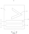
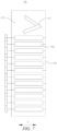
- FIG. 2 is a schematic structural diagram of a first limiting member 30 from a first perspective according to some embodiments of the present application
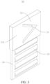
- FIG. 3 is a schematic structural diagram of a first limiting member 30 from a second perspective according to some embodiments of the present application
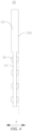
- FIG. 4 is a schematic structural diagram of a first limiting member 30 from a third perspective according to some embodiments of the present application.
- the first limiting member 30 further comprises a first limiting portion 33 and a first connecting portion 34, the first rolling body 32 being mounted on the first connecting portion 34, and the surface of the first limiting portion 33 that faces the electrode plate 200 being flush with the edge of the first rolling body 32 that is configured to abut against the uncoated region 210.
- the first limiting portion 33 is of a plate-like structure, the cutting hole of the first limiting member 30 is provided at the first limiting portion 33, the first connecting portion 34 is connected to one end of the first limiting portion 33 and located downstream of the first limiting portion 33, and the first limiting portion 33 has a thickness greater than that of the first connecting portion 34.
- the first rolling body 32 is rotatably mounted on the first connecting portion 34. The first rolling body 32 may be driven by a magnetic wheel.
- the first limiting portion 33 has a first surface 331 that faces the electrode plate 200, and the surface of the first rolling body 32 that is configured to abut against the uncoated region 210 is a circumferential face of the first rolling body 32.
- the surface of the first limiting portion 33 that faces the electrode plate 200 being flush with the edge of the first rolling body 32 that is configured to abut against the uncoated region 210 may be interpreted as the extension surface of the first surface 331 being tangent to the circumferential face of the first rolling body 32.
- the axis of rotation of the first rolling body 32 is located on a thickness central plane of the first limiting portion 33, and then the first rolling body 32 has a diameter equal to the thickness of the first limiting portion 33.
- the thickness central plane of the first limiting portion 33 refers to a plane located at the center of the first limiting portion 33 in a thickness direction of the first limiting portion 33 and parallel to the first surface 331.
- the thickness direction of the first limiting portion 33 is the same as the thickness direction A of the electrode plate, the thickness of the first limiting portion 33 refers to the dimension of the first limiting portion 33 in the thickness direction thereof, and the thickness of the first connecting portion 34 refers to the dimension of the first connecting portion 34 in the thickness direction of the first limiting portion 33.
- the surface of the first limiting portion 33 that faces the electrode plate 200 is flush with the edge of the first rolling body 32 that is configured to abut against the uncoated region 210, and then the first limiting portion 33 and the first rolling body 32 have the same distance from the electrode plate 200 to allow the electrode plate 200 to have the same range of vibration in the thickness direction, thereby improving the cutting stability and reducing the risk of large deformation of the electrode plate 200 so as to improve the forming quality of the electrode plate 200.
- FIG. 5 is a schematic structural diagram of a die-cutting device 100 according to some other embodiments of the present application.
- the die-cutting device 100 further comprises a second cutting mechanism 60 and a guide mechanism 50.
- the second cutting mechanism 60 is disposed on one side of the electrode plate 200 in the thickness direction, the second cutting mechanism 60 is disposed downstream of the first cutting mechanism 20, and the second cutting mechanism 60 is configured to cut the scrap portion to separate the scrap portion from the coated region 220.
- the guide mechanism 50 is disposed downstream of the first limiting member 30, and the guide mechanism 50 is configured to drive the scrap portion to offset towards the second cutting mechanism 60.
- the second cutting mechanism 60 is a laser light 300 cutting mechanism.
- the laser light 300 emitted by the second cutting mechanism 60 is projected on one side of the adsorption mechanism in the width direction C of the electrode plate, so as to prevent the laser light 300 emitted by the second cutting mechanism 60 from cutting the adsorption mechanism.
- the electrode plate 200 is formed in two steps by the first cutting mechanism 20 and the second cutting mechanism 60.
- the tab is separated from the scrap portion, so that during the cutting operation, the vibration of the scrap portion has little influence on the tab, so as to greatly reduce the risk of decrease of product qualification rate due to the deformation of the tab caused by the vibration of the scrap portion and the damage of the tab caused by being pulled by the scrap portion, and also improve the forming quality of the electrode plate 200.
- the first cutting mechanism 20 and the second cutting mechanism 60 are located on the same side of the electrode plate in the thickness direction A. In other embodiments, the first cutting mechanism 20 and the second cutting mechanism 60 may be located on opposite sides of the electrode plate in the thickness direction A.
- the scrap portion is cut to separate the scrap portion from the coated region 220, so that the cutting of the electrode plate 200 is completed.
- the guide mechanism 50 drives the scrap portion to offset towards the second cutting mechanism 60 to compensate for the deformation of the electrode plate 200 during the cutting process of the first cutting mechanism 20, so that the scrap portion offsets to be within the cutting range of the second cutting mechanism 60 (for the laser light 300 cutting mechanism, the cutting range is a range that the laser light 300 can reach) so as to ensure that the second cutting mechanism 60 can effectively cut the electrode plate 200.
- the guide mechanism 50 is an adsorption mechanism, and the guide mechanism 50 and the second cutting mechanism 60 are located on the same side in the thickness direction.
- the thickness direction herein refers to the thickness direction A of the electrode plate, and the guide mechanism 50 and the second cutting mechanism 60 are located on the same side of the thickness direction.
- the adsorption mechanism may be a negative pressure mechanism.
- the guide mechanism 50 and the second cutting mechanism 60 may be respectively located on two sides of the electrode plate in the thickness direction A, and the guide mechanism 50 may be a blowing mechanism configured to blow the scrap portion towards the second cutting mechanism 60 such that the scrap portion offsets towards the second cutting mechanism 60.
- the adsorption mechanism drives the uncoated region 210 by adsorption to offset towards the second cutting mechanism 60, so that the offset amount of the scrap portion can be controlled more accurately.
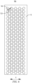
- FIG. 6 is a schematic structural diagram of an adsorption mechanism provided with adsorption holes.
- the adsorption mechanism comprises an adsorption face provided with a plurality of adsorption holes 51.
- the adsorption mechanism may comprise an adsorption belt, and the adsorption face 51 is a surface of the adsorption belt. Each adsorption hole may have a diameter of 3 mm.
- the adsorption face 51 is provided with multiple rows of first adsorption holes 52 and at least one row of second adsorption holes 53, each row of first adsorption holes 52 including at least two first adsorption holes 52 arranged at intervals in the width direction C of the electrode plate, the multiple rows of first adsorption holes 52 being arranged at intervals in the conveying direction B of the electrode plate, and one row of second adsorption holes 53 being provided between two adjacent rows of first adsorption holes 52.
- the spacing of the two adjacent rows of first adsorption holes 52 may be 2 mm, and the spacing between the two adjacent rows of second adsorption holes 53 may be 2 mm.
- the adsorption face 51 is flush with the first surface 331 of the first limiting portion 33 that is configured to abut against the uncoated region 210.
- the adsorption holes are distributed in a staggered manner, so that when the scrap portion is not completely out of control of the front row of adsorption holes, the next row of adsorption holes work, which ensures that the separation of the scrap portion from the coated region 220 is always controlled so as to avoid influence of the vibration of the scrap portion on the cutting stability.
- providing the adsorption holes can improve the adsorption stability, thereby effectively improve the cutting stability of the scrap portion.
- the guide mechanism 50 and the first limiting member 30 are located on the same side in the thickness direction; and the second limiting member 40 comprises second rolling bodies 42 configured to abut against the uncoated region 210.
- the second rolling bodies 42 may be in many structural forms, for example, the second rolling bodies 42 may be roller shafts, balls, etc.
- the guide mechanism 50 and the first limiting member 30 are located on the same side of the electrode plate in the thickness direction A, the uncoated region 210 may abut against the second limiting member 40 due to the vibration of the electrode plate 200 in the thickness direction, and the second rolling bodies 42 of the second limiting member 40 abut against the uncoated region 210, so that the uncoated region 210 is in rolling frictional contact with the second limiting member 40, and the uncoated region 210 has small friction damping, thereby improving the transmission stability of the electrode plate 200 and reducing the abrasion of the electrode plate 200, so as to effectively prevent tearing of the tab, even serious consequences such as strip breakage, due to large damping between the tab and the second limiting member 40 after the tab is separated from the scrap portion.
- FIG. 7 is a schematic structural diagram of a second limiting member according to some embodiments of the present application.
- a plurality of second rolling bodies 42 are provided, the plurality of second rolling bodies 42 are located downstream of the first cutting mechanism 20, some of the plurality of second rolling bodies 42 are located upstream of the second cutting mechanism 60, and some of the plurality of second rolling bodies 42 are located downstream of the second cutting mechanism 60.
- some of the plurality of second rolling bodies 42 may be located upstream of the first cutting mechanism 20.
- Some of the second rolling bodies 42 are disposed upstream of the second cutting mechanism 60, and some of the second rolling bodies 42 are disposed downstream of the second cutting mechanism 60, so that the scrap portion can be in rolling contact with the second limiting member 40 before and after being separated from the coated region 220, so as to reduce the resistance of the electrode plate 200 during the transmission process, improve the transmission stability of the electrode plate 200, and reduce the abrasion of the electrode plate 200.
- the second limiting member 40 further comprises a second limiting portion 43 and a second connecting portion 44, the second rolling bodies 42 being mounted on the second connecting portion 44, and the surface of the second limiting portion 43 that faces the electrode plate 200 being flush with the edges of the second rolling bodies 42 that are configured to abut against the scrap portion.
- the second limiting portion 43 is of a plate-like structure, the second limiting portion 43 is disposed opposite the first limiting portion 33, the cutting hole of the second limiting member 40 is provided at the second limiting portion 43, the second connecting portion 44 is connected to one end of the second limiting portion 43 and located downstream of the second limiting portion 43, and the second limiting portion 43 has a thickness greater than that of the second connecting portion 44.
- the second rolling bodies 42 are rotatably mounted on the second connecting portion 44.
- the second limiting portion 43 has a second surface that faces the electrode plate 200, and the surfaces of the second rolling bodies 42 that are configured to abut against the uncoated region 210 are circumferential faces of the second rolling bodies 42.
- the surface of the second limiting portion 43 that faces the electrode plate 200 being flush with the edges of the second rolling bodies 42 that are configured to abut against the uncoated region 210 may be interpreted as the extension surface of the second surface being tangent to the circumferential faces of the second rolling bodies 42.
- the axes of rotation of the second rolling bodies are located on a thickness central plane of the second limiting portion 43, and then each second rolling body 42 has a diameter equal to the thickness of the second limiting portion 43.
- the thickness central plane of the second limiting portion 43 refers to a plane located at the center of the second limiting portion 43 in a thickness direction of the second limiting portion 43 and parallel to the second surface.
- the thickness direction of the second limiting portion 43 is consistent with the thickness direction A of the electrode plate, the thickness of the second limiting portion 43 refers to the dimension of the second limiting portion 43 in the thickness direction thereof, and the thickness of the second connecting portion 44 refers to the dimension of the second connecting portion 44 in the thickness direction of the second limiting portion 43.
- the surface of the second limiting portion 43 that faces the electrode plate 200 is flush with the edges of the second rolling bodies 42 that are configured to abut against the uncoated region 210, and then the second limiting portion 43 and the second rolling bodies 42 have the same distance from the electrode plate 200 to allow the electrode plate 200 to have the same range of vibration in the thickness direction, thereby improving the cutting stability and reducing the risk of large deformation of the electrode plate 200 so as to improve the forming quality of the electrode plate 200.
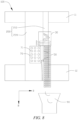
- FIG. 8 is a schematic structural diagram of a die-cutting device 100 according to some embodiments of the present application.
- the die-cutting device 100 further comprises a third limiting member 70, and in the thickness direction, the third limiting member 70 is arranged on one side of the coated region 220, and the third limiting member 70 is configured to limit the coated region 220 in an offset direction of the scrap portion.
- the third limiting member 70 is of a plate-like structure, and in the width direction C of the electrode plate, the third limiting member 70 and the guide mechanism 50 are arranged side by side at an interval, and the laser light 300 emitted by the second cutting mechanism 60 passes between the third limiting member 70 and the guide mechanism 50 and is then projected to the electrode plate 200.
- the coated region 220 is limited by the third limiting member 70 in the offset direction of the scrap portion, so that the maximum deformation of the electrode plate 200 is limited so as to improve the forming quality of the electrode plate 200.
- the third limiting member 70 is provided with a plurality of through holes 71.
- the plurality of through holes 71 may be arranged in many ways, such as arranged in a rectangular array or arranged in a circular array.
- the through holes 71 are provided such that dust is not easy to accumulate on the third limiting member 70, and providing the through holes 71 can also reduce the weight of the third limiting member 70.
- the die-cutting device 100 further comprises a dust removal mechanism 80 (shown in FIG. 5 ).
- the dust removal mechanism 80 is configured to remove dust generated on the electrode plate 200 when the second cutting mechanism 60 cuts the scrap portion of the electrode plate 200.
- two dust removal mechanisms 80 may be provided.
- the two dust removal mechanisms 80 are respectively disposed on two sides of the electrode plate in the thickness direction A so as to remove dust from the electrode plate 200 from two sides of the electrode plate in the thickness direction A, thereby improving the dust removal efficiency.
- a dust removal mechanism 80 may be provided corresponding to a cutting position of the first cutting mechanism 20 to remove dust generated on the electrode plate 200 when the first cutting mechanism 20 cuts the electrode plate 200 to form a tab.
- the dust removal mechanism 80 corresponding to the first cutting mechanism 20 may be disposed on one side or both sides of the electrode plate 200 in the width direction, and dust can be adsorbed on one side of the electrode plate in the width direction C by means of a negative pressure dust removal mechanism 80.
- the dust removal mechanism 80 may be a negative pressure dust removal mechanism 80, and in the case where two negative pressure dust removal mechanisms 80 are distributed on two sides of the electrode plate in the thickness direction A, according to an actual sputtering trajectory of dust generated in front of and behind the electrode plate 200, convection negative pressure dust removal mechanisms 80 are designed in front of and behind a cutting point of the electrode plate 200, thereby improving the dust removal efficiency while not affecting the cutting stability.
- the dust removal mechanism 80 may be a dust removal mechanism 80 in other forms.
- a coating of part of the coated region 220 will be generally cut during the process of separating the scrap portion from the coated region 220, and a lot of dust will be generated when the coating is cut.
- the dust removal mechanism 80 is configured to remove the dust generated on the electrode plate 200 when the second cutting mechanism 60 cuts the scrap portion of the electrode plate 200, so as to maintain a clean cutting environment and avoid influence of the dust on the cutting operation of the second cutting mechanism 60, which is conducive to improving the forming quality of the electrode plate 200.
- the die-cutting device 100 further comprises a scrap collection mechanism 90.
- the scrap collection mechanism 90 is disposed downstream of the second cutting mechanism 60, and the scrap collection mechanism 90 is configured to collect the scrap portion separated from the coated region 220.
- the die-cutting device 100 comprises a conveying mechanism 10, a first cutting mechanism 20, a first limiting member 30, a second limiting member 40, a guide mechanism 50, a second cutting mechanism 60, a third limiting member 70, two dust removal mechanisms 80 and a scrap collection mechanism 90.
- the first limiting member 30 and the second limiting member 40 are arranged opposite each other on two sides of an electrode plate in a thickness direction A, the first limiting member 30 is provided with a V-shaped first cutting hole 31, the first cutting mechanism 20 is disposed on the side of the first limiting member 30 that faces away from the electrode plate 200 in the thickness direction A of the electrode plate, the first cutting mechanism 20 is a laser light 300 cutting mechanism, and the laser light 300 emitted by the first cutting mechanism 20 passes through the first cutting hole 31 and cuts an uncoated region 210 of the electrode plate 200 such that the uncoated region 210 forms a scrap portion connected to the coated region 220 and a tab connected to the coated region 220 and separated from the scrap portion.
- the first limiting member 30 comprises a first limiting portion 33, a first connecting portion 34 and a plurality of first rolling bodies 32, the first connecting portion 34 being connected to the first limiting portion 33 and located downstream of the first limiting portion 33, and the first rolling bodies 32 being rotatably connected to the first connecting portion 34.
- the second cutting mechanism 60 and the guide mechanism 50 are both located downstream of the first cutting mechanism 20, and the second cutting mechanism 60, the guide mechanism 50, the third limiting member 70 and the first cutting mechanism 20 are located on the same side of the electrode plate in the thickness direction A.
- the second cutting mechanism 60 is configured to cut the scrap portion to separate the scrap portion from the coated region 220.
- the second cutting mechanism 60 is a laser light 300 cutting mechanism, and the guide mechanism 50 is an adsorption mechanism.
- the second limiting member 40 comprises a second limiting portion 43, a second connecting portion 44 and a plurality of second rolling bodies 42.
- the second connecting portion 44 is connected to the second limiting portion 43 and located downstream of the second limiting portion 43, the second rolling bodies 42 are rotatably connected to the second connecting portion 44, some of the second rolling bodies 42 are located downstream of the second cutting mechanism 60, and some of the second rolling bodies 42 are located upstream of the second cutting mechanism 60.
- a plurality of through holes 71 are provided on the third limiting member 70, and the third limiting member 70 is configured to limit the coated region 220 in an offset direction of the scrap portion.
- the two dust removal mechanisms 80 are respectively disposed on two sides of the electrode plate in the thickness direction A to form dust absorption by convection, so as to remove dust generated on the electrode plate 200 when the second cutting mechanism 60 cuts the scrap portion of the electrode plate 200.
- the scrap collection mechanism 90 is disposed downstream of the second cutting mechanism 60 to collect the scrap portion separated from the coated region 220.
Landscapes
- Engineering & Computer Science (AREA)
- Optics & Photonics (AREA)
- Physics & Mathematics (AREA)
- Mechanical Engineering (AREA)
- General Chemical & Material Sciences (AREA)
- Chemical & Material Sciences (AREA)
- Electrochemistry (AREA)
- Chemical Kinetics & Catalysis (AREA)
- Plasma & Fusion (AREA)
- Manufacturing & Machinery (AREA)
- Battery Electrode And Active Subsutance (AREA)
- Laser Beam Processing (AREA)
- Perforating, Stamping-Out Or Severing By Means Other Than Cutting (AREA)
- Arc Welding In General (AREA)
Abstract
Description
- The present application claims the priority to
Chinese patent application no. 202122410066.6, filed on September 30, 2021 - The present application relates to the technical field of battery manufacturing, and in particular to a die-cutting device.
- At present, lithium batteries are widely used in electronic products, vehicles, aerospace and other fields. The increasingly complex application environments and conditions put forward higher requirements for the batteries in terms of safety performance, energy density, production cost, etc.
- The forming quality of electrode plates of the lithium-ion batteries has a great influence on the batteries in terms of safety performance, energy density, production cost, etc. Thus, how to improve the forming quality of the electrode plates has become an urgent problem to be solved in the battery manufacturing process.
- According to the embodiments of the present application, a die-cutting device is provided to improve the forming quality of an electrode plate.
- In a first aspect, according to an embodiment of the present application, a die-cutting device is provided, comprising a conveying mechanism, a first cutting mechanism, a first limiting member and a second limiting member. The conveying mechanism is configured to convey an electrode plate that comprises an uncoated region and a coated region, the uncoated region being connected to the coated region. The first cutting mechanism is located on one side of the electrode plate in a thickness direction, and the first cutting mechanism is configured to cut the uncoated region such that the uncoated region forms a scrap portion connected to the coated region and a tab connected to the coated region and separated from the scrap portion. The first limiting member is located between the electrode plate and the first cutting mechanism in the thickness direction, and the first limiting member is provided with a cutting hole that allows laser light emitted by the first cutting mechanism to pass through, the cutting hole matching a cutting trajectory of the laser light. The second limiting member is located on the side of the electrode plate that faces away from the first limiting member in the thickness direction, and the second limiting member is configured to cooperate with the first limiting member to limit the electrode plate in the thickness direction.
- In the above technical solution, during the process of cutting the electrode plate to form the tab, both a conveying force of the conveying mechanism and a cutting force of the cutting mechanism may cause the electrode plate to vibrate in the thickness direction, resulting in unstable cutting to affect the cutting quality of the tab, and an excessive vibration amplitude of the electrode plate may also cause the electrode plate to be out of a cutting range of the cutting mechanism, resulting in incomplete cutting or inability to achieve cutting. The first limiting member and the second limiting member are respectively provided on the two sides of the electrode plate and respectively limit the electrode plate on the two sides of the electrode plate in the thickness direction, so as to cooperatively limit the range of vibration of the electrode plate in the thickness direction to improve the cutting stability, thereby improving the forming quality of the electrode plate. The first limiting member is located between the electrode plate and the first cutting mechanism in the thickness direction of the electrode plate, and the cutting hole is provided to allow the laser light emitted by the first cutting mechanism to pass through, so as to cut the electrode plate and prevent the laser light from cutting the first limiting member.
- In some embodiments in the first aspect of the present application, the first limiting member and the second limiting member at least partially overlap in the thickness direction to form an overlapping region, and the first cutting mechanism is configured to cut the uncoated region in the overlapping region.
- In the above technical solution, the first cutting mechanism cuts the uncoated region in the overlapping region formed by the first limiting member and the second limiting member. Thus, the two sides of the electrode plate in the thickness direction corresponding to the cutting region of the first cutting mechanism are both limited, which can limit the range of vibration of the electrode plate in the thickness direction and can limit the degree of vibration of the electrode plate in the thickness direction of the electrode plate within the cutting range of the first cutting mechanism, so that the cutting stability can be improved.
- In some embodiments in the first aspect of the present application, the first limiting member comprises a first rolling body configured to abut against the uncoated region.
- In the above technical solution, the vibration of the electrode plate in the thickness direction may cause the uncoated region of the electrode plate to abut against the first limiting member, and the first rolling body of the first limiting member abuts against the uncoated region. Thus, the uncoated region is in rolling frictional contact with the first limiting member, and the uncoated region has small friction damping, thereby improving the transmission stability of the electrode plate and reducing the abrasion of the electrode plate, so as to effectively prevent tearing of the tab, even serious consequences such as strip breakage, due to large damping between the tab and the first limiting member after the tab is separated from the scrap portion.
- In some embodiments in the first aspect of the present application, the first rolling body is disposed downstream of the first cutting mechanism.
- In the above technical solution, since the scrap portion and the tab do not restrict each other after the scrap portion is separated from the tab, the tab and the scrap portion are both easily stuck with the first limiting member when they are in contact with the first limiting member. Thus, the first rolling body is disposed downstream of the first cutting mechanism, so that the separated tab and the scrap portion may both be in rolling fit with the first limiting member, so as to reduce the risk of tearing of the tab and strip breakage caused by the tab and the scrap portion being stuck with the first limiting member.
- In some embodiments in the first aspect of the present application, the first limiting member further comprises a first limiting portion and a first connecting portion, the first rolling body being mounted on the first connecting portion, and the surface of the first limiting member that faces the electrode plate being flush with the edge of the first rolling body that is configured to abut against the uncoated region.
- In the above technical solution, the surface of the first limiting portion that faces the electrode plate is flush with the edge of the first rolling body that is configured to abut against the uncoated region, and then the first limiting portion and the first rolling body have the same distance from the electrode plate to allow the electrode plate to have the same range of vibration in the thickness direction. Thereby the cutting stability is improved and the risk of large deformation of the electrode plate is reduced so as to improve the forming quality of the electrode plate.
- In some embodiments in the first aspect of the present application, the die-cutting device further comprises: a second cutting mechanism and a guide mechanism. The second cutting mechanism is disposed on one side of the electrode plate in the thickness direction, the second cutting mechanism is disposed downstream of the first cutting mechanism, and the second cutting mechanism is configured to cut the scrap portion to separate the scrap portion from the coated region. The guide mechanism is disposed downstream of the first limiting member, and the guide mechanism is configured to drive the scrap portion to offset towards the second cutting mechanism.
- In the above technical solution, the electrode plate is formed in two steps by the first cutting mechanism and the second cutting mechanism. In the first step, the tab is separated from the scrap portion, so that during the cutting operation, the vibration of the scrap portion has little influence on the tab, so as to greatly reduce the risk of decrease of product qualification rate due to the deformation of the tab caused by the vibration of the scrap portion and the damage of the tab caused by being pulled by the scrap portion, and also improve the forming quality of the electrode plate. After the scrap portion is separated from the tab, the scrap portion is cut to separate the scrap portion from the coated region, so that the cutting of the electrode plate is completed. The guide mechanism drives the scrap portion to offset towards the second cutting mechanism to compensate for the deformation of the electrode plate during the cutting process of the first cutting mechanism, so that the scrap portion offsets to be within the cutting range of the second cutting mechanism to ensure that the second cutting mechanism can effectively cut the electrode plate.
- In some embodiments in the first aspect of the present application, the guide mechanism is an adsorption mechanism, and the guide mechanism is located on the same side as the second cutting mechanism in the thickness direction.
- In the above technical solution, the guide mechanism is the adsorption mechanism, and the uncoated region is driven by adsorption to offset towards the second cutting mechanism, so that the offset amount of the scrap portion can be controlled more accurately.
- In some embodiments in the first aspect of the present application, the adsorption mechanism comprises an adsorption face provided with a plurality of adsorption holes.
- In the above technical solution, providing the adsorption holes can improve the adsorption stability, thereby effectively improving the cutting stability of the scrap portion.
- In some embodiments in the first aspect of the present application, the guide mechanism is located on the same side as the first limiting member in the thickness direction; and the second limiting member comprises second rolling bodies configured to abut against the uncoated region.
- In the above technical solution, the guide mechanism and the first limiting member are located on the same side of the electrode plate in the thickness direction, the uncoated region may abut against the second limiting member due to the vibration of the electrode plate in the thickness direction, and the second rolling bodies of the second limiting member abut against the uncoated region. Thus, the uncoated region is in rolling frictional contact with the second limiting member, and the uncoated region has small friction damping, thereby improving the transmission stability of the electrode plate and reducing the abrasion of the electrode plate, so as to effectively prevent tearing of the tab, even serious consequences such as strip breakage, due to large damping between the tab and the second limiting member after the tab is separated from the scrap portion.
- In some embodiments in the first aspect of the present application, a plurality of second rolling bodies are provided and located downstream of the first cutting mechanism, some of the plurality of second rolling bodies being located upstream of the second cutting mechanism, and some of the plurality of second rolling bodies being located downstream of the second cutting mechanism.
- In the above technical solution, some of the second rolling bodies are disposed upstream of the second cutting mechanism, and some are disposed downstream of the second cutting mechanism, so that the scrap portion can be in rolling contact with the second limiting member before and after being separated from the coated region, so as to reduce the resistance of the electrode plate during the transmission process, improve the transmission stability of the electrode plate, and reduce the abrasion of the electrode plate.
- In some embodiments in the first aspect of the present application, the second limiting member further comprises a second limiting portion and a second connecting portion, the second rolling bodies being mounted on the second connecting portion, and the surface of the second limiting portion that faces the electrode plate being flush with the edges of the second rolling bodies that are configured to abut against the scrap portion.
- In the above technical solution, the surface of the second limiting portion that faces the electrode plate is flush with the edges of the second rolling bodies that are configured to abut against the uncoated region, and then the second limiting portion and the second rolling bodies have the same distance from the electrode plate to allow the electrode plate to have the same range of vibration in the thickness direction, thereby improving the cutting stability and reducing the risk of large deformation of the electrode plate so as to improve the forming quality of the electrode plate.
- In some embodiments in the first aspect of the present application, the die-cutting device further comprises a third limiting member disposed on one side of the coated region in the thickness direction and configured to limit the coated region in an offset direction of the scrap portion.
- In the above technical solution, since the scrap portion will make the coated region offset to cause deformation of the electrode plate during the process of the guide mechanism driving the scrap portion to offset towards the second cutting mechanism, the coated region is limited by the third limiting member in the offset direction of the scrap portion, so that the maximum deformation of the electrode plate can be limited so as to improve the forming quality of the electrode plate.
- In some embodiments in the first aspect of the present application, the third limiting member is provided with a plurality of through holes.
- In the above technical solution, the third limiting member is provided with the plurality of through holes, so that dust is not easy to accumulate on the third limiting member, and providing the through holes can also reduce the weight of the third limiting member.
- In some embodiments in the first aspect of the present application, the die-cutting device further comprises a dust removal mechanism configured to remove dust generated on the electrode plate when the second cutting mechanism cuts the scrap portion of the electrode plate.
- In the above technical solution, a coating of part of the coated region will be generally cut during the process of separating the scrap portion from the coated region, and a lot of dust will be generated when the coating is cut. The dust removal mechanism is configured to remove dust generated on the electrode plate when the second cutting mechanism cuts the scrap portion of the electrode plate, so as to maintain a clean cutting environment and avoid the influence of dust on the cutting operation of the second cutting mechanism, which is conducive to improving the forming quality of the electrode plate.
- In some embodiments in the first aspect of the present application, the conveying mechanism comprises a first transmission roller and a second transmission roller which cooperate to convey the electrode plate, and the first limiting member and the second limiting member are both located between the first transmission roller and the second transmission roller in a conveying direction of the electrode plate.
- In the above technical solution, the first transmission roller and the second transmission roller cooperate to convey the electrode plate, so that the convey stability can be improved so as to improve the cutting stability and the forming quality of the electrode plate.
- In order to more clearly describe the technical solutions of the embodiments of the present application, the accompanying drawings required in the embodiments will be described briefly below. It should be understood that the following accompanying drawings illustrate only some embodiments of the present application and therefore should not be construed as a limitation on the scope thereof. For those of ordinary skill in the art, other relevant accompanying drawings can also be obtained from these accompanying drawings without any creative effort.
-
FIG. 1 is a schematic structural diagram of a die-cutting device according to some embodiments of the present application; -
FIG. 2 is a schematic structural diagram of a first limiting member from a first perspective according to some embodiments of the present application; -
FIG. 3 is a schematic structural diagram of a first limiting member from a second perspective according to some embodiments of the present application; -
FIG. 4 is a schematic structural diagram of a first limiting member from a third perspective according to some embodiments of the present application; -
FIG. 5 is a schematic structural diagram of a die-cutting device according to some other embodiments of the present application; -
FIG. 6 is a schematic structural diagram of an adsorption mechanism provided with adsorption holes; -
FIG. 7 is a schematic structural diagram of a second limiting member according to an embodiment of the present application; and -
FIG. 8 is a schematic structural diagram of a die-cutting device according to further embodiments of the present application. - List of reference signs: 100 - die-cutting device; 10 - conveying mechanism; 11 - first transmission roller; 12 - second transmission roller; 20 - first cutting mechanism; 30 - first limiting member; 31 - first cutting hole; 32 - first rolling body; 33 - first limiting portion; 331 - first surface; 34 - first connecting portion; 40 - second limiting member; 41 - second cutting hole; 42 - second rolling body; 43 - second limiting portion; 44 - second connecting portion; 50 - guide mechanism; 51 - adsorption face; 52 - first adsorption hole; 53 - second adsorption hole; 60 - second cutting mechanism; 70 - third limiting member; 71 - through hole; 80 - dust removal mechanism; 90 - scrap collection mechanism; 200 - electrode plate; 210 - uncoated region; 220 - coated region; 300 - laser light; A - thickness direction of electrode plate; B - conveying direction of electrode plate; C - width direction of electrode plate.
- In order to make the objects, technical solutions and advantages of embodiments of the present application clearer, the technical solutions in the embodiments of the present application will be described clearly and completely below with reference to the accompanying drawings in the embodiments of the present application. Obviously, the embodiments described are some of, rather than all of, the embodiments of the present application. Generally, the assemblies of the embodiments of the present application described and illustrated in the accompanying drawings herein may be arranged and designed in a variety of different configurations.
- Thus, the following detailed description of the embodiments of the present application provided in the accompanying drawings is not intended to limit the scope of the present application as claimed, but is merely representative of the selected embodiments of the present application. All the other embodiments obtained by those of ordinary skill in the art based on the embodiments of the present application without any creative effort shall fall within the scope of protection of the present application.
- It should be noted that the embodiments in the present application and features in the embodiments may be combined with each other without conflicts.
- It should be noted that like numerals and letters refer to like items in the following accompanying drawings, so once an item is defined in one accompanying drawing, it does not require further definition and explanation in subsequent accompanying drawings.
- In the description of the embodiments of the present application, it should be noted that the indicated orientations or positional relationships are based on the orientations or positional relationships shown in the accompanying drawings or are orientations or positional relationships in which a product of the present application is conventionally placed when in use, or the orientations or positional relationships commonly understood by those skilled in the art, and are intended to facilitate the description of the present application and simplify the description only, rather than indicating or implying that the device or element referred to must have a particular orientation or be constructed and operated in a particular orientation, and will not to be interpreted as limiting the present application. In addition, the terms "first", "second", "third", etc. are merely used for distinct description, and shall not be construed as indicating or implying relative importance.
- At present, from the perspective of the development of the market situation, the traction batteries are used more and more widely. The traction batteries are not only used in energy storage power systems such as hydroelectric power plants, thermal power plants, wind power plants and solar power plants, but also widely used in electric transportation means such as electric bicycles, electric motorcycles and electric vehicles and in many fields such as military equipment and aerospace. With the continuous expansion of the application field of traction batteries, the market demand for the traction batteries is also expanding.
- A battery cell of the battery comprises an electrode assembly and an electrolyte, and the electrode assembly is composed of a positive electrode plate, a negative electrode plate and a separator. The operation of the battery monomer mainly relies on the movement of metal ions between the positive electrode plate and the negative electrode plate.
- The positive electrode plate and the negative electrode plate each comprises a coated region and an uncoated region, and the uncoated region is connected to the coated region and protrudes from the coated region in a width direction of the electrode plate. In the positive electrode plate, the coated region is coated with a positive active material layer, and the positive active material may be lithium cobaltate, lithium iron phosphate, ternary lithium or lithium manganate, etc. In the negative electrode plate, the coated region is coated with a negative active material layer, and the negative active material may be carbon or silicon, etc. A tab of the electrode plate is formed in the uncoated region. In some other embodiments, in order to ensure the structural strength of the tab, the portion of the tab close to the coated region may also be coated with a certain active material layer.
- The inventor has found that, in the prior art, no matter it is a positive electrode plate or a negative electrode plate, during the process of cutting an uncoated region to form a tab, both a conveying force of a conveying mechanism and a cutting force of a cutting mechanism of the electrode plate cause the electrode plate to vibrate greatly in a thickness direction of the electrode plate, resulting in poor cutting stability, and an excessive vibration amplitude of the electrode plate may also cause the electrode plate to be out of a cutting range of the cutting mechanism, resulting in incomplete cutting or inability to achieve cutting to seriously affect the forming quality of the electrode plate.
- On the basis of the above considerations, in order to solve the problem of poor forming quality of an electrode plate caused by the vibration of the electrode plate during the process of cutting the electrode plate to form a tab, the inventor has designed, through in-depth research, a die-cutting device in which a first limiting member, which has a cutting hole that allows laser light to pass through, and a second limiting member are respectively provided on two sides of an electrode plate, and respectively limit the electrode plate on the two sides of the electrode plate in a thickness direction, so as to cooperatively limit the range of vibration of the electrode plate in the thickness direction to improve the cutting stability, thereby improving the forming quality of the electrode plate. The first limiting member is located between the electrode plate and the first cutting mechanism in the thickness direction of the electrode plate, and the cutting hole is provided to allow the laser light emitted by the first cutting mechanism to pass through, so as to cut the electrode plate and prevent the laser light from cutting the first limiting member.
- Referring to
FIG. 1, FIG. 1 is a schematic structural diagram of a die-cuttingdevice 100 according to some embodiments of the present application. The die-cuttingdevice 100 comprises a conveyingmechanism 10, afirst cutting mechanism 20, a first limitingmember 30 and a second limitingmember 40. The conveyingmechanism 10 is configured to convey anelectrode plate 200. Theelectrode plate 200 comprises an uncoated region 210 (shown inFIG. 8 ) and a coated region 220 (shown inFIG. 8 ), theuncoated region 210 being connected to thecoated region 220. Thefirst cutting mechanism 20 is located on one side of the electrode plate in a thickness direction A, and thefirst cutting mechanism 20 is configured to cut theuncoated region 210 to allow theuncoated region 210 to form a scrap portion (not shown in the figure) connected to thecoated region 220 and a tab (not shown in the figure) connected to thecoated region 220 and separated from the scrap portion. The first limitingmember 30 is located between theelectrode plate 200 and thefirst cutting mechanism 20 in the thickness direction, and the first limitingmember 30 is provided with a cutting hole (shown inFIG. 2 and defined as a first cutting hole 31) that allowslaser light 300 emitted by thefirst cutting mechanism 20 to pass through, the cutting hole matching a cutting trajectory of thelaser light 300. The second limitingmember 40 is located on the side of theelectrode plate 200 that faces away from the first limitingmember 30 in the thickness direction, and the second limitingmember 40 is configured to cooperate with the first limitingmember 30 to limit theelectrode plate 200 in the thickness direction. - In some embodiments, the conveying
mechanism 10 includes afirst transmission roller 11 and asecond transmission roller 12. Thefirst transmission roller 11 and thesecond transmission roller 12 cooperate to convey theelectrode plate 200, and the first limitingmember 30 and the second limitingmember 40 are located between thefirst transmission roller 11 and thesecond transmission roller 12 in a conveying direction B of theelectrode plate 200. The conveyingmechanism 10 conveys theelectrode plate 200 to thefirst cutting mechanism 20 at a certain speed, and the first cutting mechanism emits thelaser light 300 to theelectrode plate 200 to cut theuncoated region 210. - The
first transmission roller 11 and thesecond transmission roller 12 cooperate to convey theelectrode plate 200, so that the conveying stability can be improved so as to improve the cutting stability and the forming quality of theelectrode plate 200. - The
first cutting mechanism 20 is located on one side of the electrode plate in the thickness direction A, and the first limitingmember 30 is located between theelectrode plate 200 and thefirst cutting mechanism 20 in the thickness direction A of the electrode plate. Thelaser light 300 triggered by thefirst cutting mechanism 20 passes through the cutting hole in the first limitingmember 30 and then acts on theelectrode plate 200 to cut theuncoated region 210 of theelectrode plate 200. Thefirst cutting mechanism 20 is alaser light 300 cutting mechanism, the conveyingmechanism 10 conveys theelectrode plate 200 to thefirst cutting mechanism 20 at a certain speed, and the first cutting mechanism emits thelaser light 300 to theelectrode plate 200 to cut theuncoated region 210. - The cutting hole (the first cutting hole 31) matches the cutting trajectory of the laser light 300 (the laser light emitted by the first cutting mechanism 20), so that it may be understood that the shape of the cutting hole is the same as the moving trajectory of the
laser light 300 emitted by thefirst cutting mechanism 20, and it may also be understood that thelaser light 300 emitted by thefirst cutting mechanism 20 can move in the cutting hole, so as to cut theelectrode plate 200 without cutting the first limitingmember 30. The cutting hole may be in various shapes, for example, the cutting hole is in a rectangular shape, an I-shape, a circular shape, etc., as long as the first limitingmember 30 can achieve avoidance for thelaser light 300 emitted by thefirst cutting mechanism 20. - In some embodiments, the second limiting
member 40 may also be provided with a cutting hole, the cutting hole in the first limitingmember 30 is disposed opposite the cutting hole in the second limitingmember 40 in the thickness direction A of the electrode plate, and the cutting hole in the second limitingmember 40 also allows thelaser light 300 emitted by thefirst cutting mechanism 20 to pass through, so as to prevent thelaser light 300 passing through theelectrode plate 200 from cutting the second limitingmember 40. The shape and size of the cutting hole provided in the second limitingmember 40 may refer to the shape and size of the cutting hole provided in the first limitingmember 30. For convenience of illustration in the figures, the cutting hole in the first limitingmember 30 is defined as afirst cutting hole 31, and the cutting hole in the second limitingmember 40 is defined as a second cutting hole 41 (shown inFIG. 7 ). - During the process of cutting the
electrode plate 200 to form the tab, both a conveying force of the conveyingmechanism 10 and a cutting force of the cutting mechanism may cause theelectrode plate 200 to vibrate in the thickness direction, resulting in unstable cutting to affect the cutting quality of the tab, and an excessive vibration amplitude of theelectrode plate 200 may also cause theelectrode plate 200 to be out of a cutting range of the cutting mechanism, resulting in incomplete cutting or inability to achieve cutting. The first limitingmember 30 and the second limitingmember 40 are respectively provided on the two sides of theelectrode plate 200, so that the first limitingmember 30 and the second limitingmember 40 respectively limit theelectrode plate 200 on the two sides of the electrode plate in the thickness direction A, so as to cooperatively limit the range of vibration of theelectrode plate 200 in the thickness direction to improve the cutting stability, thereby improving the forming quality of theelectrode plate 200. The first limitingmember 30 is located between theelectrode plate 200 and thefirst cutting mechanism 20 in the thickness direction A of the electrode plate, and the cutting hole is provided to allow thelaser light 300 emitted by thefirst cutting mechanism 20 to pass through, so as to cut theelectrode plate 200 and prevent thelaser light 300 from cutting the first limitingmember 30. - Referring to
FIG. 1 , in some embodiments, the first limitingmember 30 and the second limitingmember 40 at least partially overlap in the thickness direction to form an overlapping region, and thefirst cutting mechanism 20 is configured to cut theuncoated region 210 in the overlapping region. - The thickness direction herein refers to the thickness direction A of the electrode plate. The first limiting
member 30 and the second limitingmember 40 at least partially overlapping to form the overlapping region actually means that the projections of the first limitingmember 30 and the second limitingmember 40 on theelectrode plate 200 at least partially overlap in the thickness direction A of the electrode plate. It may be that two ends of the first limitingmember 30 are flush with two ends of the second limitingmember 40 in a conveying direction B of the electrode plate. It may also be that one end of the first limitingmember 30 is flush with one end of the second limitingmember 40 in the conveying direction B of the electrode plate, and the other end of the second limitingmember 40 is beyond the other end of the first limitingmember 30 in the conveying direction B of the electrode plate (which is as the relative relationship between the first limitingmember 30 and the second limitingmember 40 as shown inFIG. 1 ); or in the conveying direction B of the electrode plate, one end of the first limitingmember 30 is beyond one end of the second limitingmember 40 in the opposite direction of the conveying direction B of the electrode plate, and the other end of the second limitingmember 40 is beyond the other end of the second limitingmember 40 in the conveying direction B of the electrode plate. The first limitingmember 30 and the second limitingmember 40 both cover at least part of theuncoated region 210 in a width direction C of the electrode plate. - The
laser light 300 emitted by thefirst cutting mechanism 20 is projected in the overlapping region. Thefirst cutting mechanism 20 cuts theuncoated region 210 in the overlapping region formed by the first limitingmember 30 and the second limitingmember 40, so that the two sides of theelectrode plate 200 in the thickness direction corresponding to the cutting region of thefirst cutting mechanism 20 are both limited, which can limit the range of vibration of theelectrode plate 200 in the thickness direction A and can limit the vibration degree of theelectrode plate 200 in the thickness direction A of the electrode plate within the cutting range of thefirst cutting mechanism 20, so that the cutting stability can be improved. - In some embodiments, the first limiting
member 30 comprises a first rollingbody 32 configured to abut against theuncoated region 210. - The
first rolling body 32 may be in many structural forms, for example, the first rollingbody 32 may be a roller shaft, a ball, etc. - the vibration of the
electrode plate 200 in the thickness direction may cause theuncoated region 210 of theelectrode plate 200 to abut against the first limitingmember 30, and the first rollingbody 32 of the first limitingmember 30 abuts against theuncoated region 210, so that theuncoated region 210 is in rolling frictional contact with the first limitingmember 30, and theuncoated region 210 has small friction damping, thereby improving the transmission stability of theelectrode plate 200 and reducing the abrasion of theelectrode plate 200, so as to effectively prevent tearing of the tab, even serious consequences such as strip breakage, due to large damping between the tab and the first limitingmember 30 after the tab is separated from the scrap portion. - In some embodiments, the first rolling
body 32 is disposed downstream of thefirst cutting mechanism 20. - It should be noted that "upstream" and "downstream" mentioned in context of embodiments of the present application refer to production sequences, the upstream referring to the production sequence coming first, and the downstream referring to the production sequence coming later, instead of defining spatial positions of the components.
- One or more (two or above) first rolling
bodies 32 may be provided. In an embodiment where a plurality of first rollingbodies 32 are provided, some of the first rollingbodies 32 in the plurality of first rollingbodies 32 may be located upstream of thefirst cutting mechanism 20, and the other first rollingbodies 32 may be located downstream of thefirst cutting mechanism 20. In the case where a plurality of first rollingbodies 32 are provided, the plurality of first rollingbodies 32 may all be located downstream of thefirst cutting mechanism 20. As shown inFIG. 1 , the first rollingbodies 32 are roller shafts, and the plurality of roller shafts are arranged side by side in parallel and at intervals in a conveying direction of theelectrode plate 200. - Since the scrap portion and the tab do not restrict each other after the scrap portion is separated from the tab, the tab and the scrap portion are both easily stuck with the first limiting
member 30 when they are in contact with the first limitingmember 30. Thus, the first rollingbody 32 is disposed downstream of thefirst cutting mechanism 20, so that the separated tab and the scrap portion may both be in rolling fit with the first limitingmember 30, so as to reduce the risk of tearing of the tab and strip breakage caused by the tab and the scrap portion being stuck with the first limitingmember 30. - Referring to
FIGS. 1 ,2 ,3 and4 ,FIG. 2 is a schematic structural diagram of a first limitingmember 30 from a first perspective according to some embodiments of the present application,FIG. 3 is a schematic structural diagram of a first limitingmember 30 from a second perspective according to some embodiments of the present application, andFIG. 4 is a schematic structural diagram of a first limitingmember 30 from a third perspective according to some embodiments of the present application. In some embodiments, the first limitingmember 30 further comprises a first limitingportion 33 and a first connectingportion 34, the first rollingbody 32 being mounted on the first connectingportion 34, and the surface of the first limitingportion 33 that faces theelectrode plate 200 being flush with the edge of the first rollingbody 32 that is configured to abut against theuncoated region 210. - The first limiting
portion 33 is of a plate-like structure, the cutting hole of the first limitingmember 30 is provided at the first limitingportion 33, the first connectingportion 34 is connected to one end of the first limitingportion 33 and located downstream of the first limitingportion 33, and the first limitingportion 33 has a thickness greater than that of the first connectingportion 34. Thefirst rolling body 32 is rotatably mounted on the first connectingportion 34. Thefirst rolling body 32 may be driven by a magnetic wheel. - The first limiting
portion 33 has afirst surface 331 that faces theelectrode plate 200, and the surface of the first rollingbody 32 that is configured to abut against theuncoated region 210 is a circumferential face of the first rollingbody 32. The surface of the first limitingportion 33 that faces theelectrode plate 200 being flush with the edge of the first rollingbody 32 that is configured to abut against theuncoated region 210 may be interpreted as the extension surface of thefirst surface 331 being tangent to the circumferential face of the first rollingbody 32. In some embodiments, the axis of rotation of the first rollingbody 32 is located on a thickness central plane of the first limitingportion 33, and then the first rollingbody 32 has a diameter equal to the thickness of the first limitingportion 33. The thickness central plane of the first limitingportion 33 refers to a plane located at the center of the first limitingportion 33 in a thickness direction of the first limitingportion 33 and parallel to thefirst surface 331. The thickness direction of the first limitingportion 33 is the same as the thickness direction A of the electrode plate, the thickness of the first limitingportion 33 refers to the dimension of the first limitingportion 33 in the thickness direction thereof, and the thickness of the first connectingportion 34 refers to the dimension of the first connectingportion 34 in the thickness direction of the first limitingportion 33. - The surface of the first limiting
portion 33 that faces theelectrode plate 200 is flush with the edge of the first rollingbody 32 that is configured to abut against theuncoated region 210, and then the first limitingportion 33 and the first rollingbody 32 have the same distance from theelectrode plate 200 to allow theelectrode plate 200 to have the same range of vibration in the thickness direction, thereby improving the cutting stability and reducing the risk of large deformation of theelectrode plate 200 so as to improve the forming quality of theelectrode plate 200. - Referring to
FIG. 5, FIG. 5 is a schematic structural diagram of a die-cuttingdevice 100 according to some other embodiments of the present application. In some embodiments, the die-cuttingdevice 100 further comprises asecond cutting mechanism 60 and aguide mechanism 50. Thesecond cutting mechanism 60 is disposed on one side of theelectrode plate 200 in the thickness direction, thesecond cutting mechanism 60 is disposed downstream of thefirst cutting mechanism 20, and thesecond cutting mechanism 60 is configured to cut the scrap portion to separate the scrap portion from thecoated region 220. Theguide mechanism 50 is disposed downstream of the first limitingmember 30, and theguide mechanism 50 is configured to drive the scrap portion to offset towards thesecond cutting mechanism 60. - The
second cutting mechanism 60 is alaser light 300 cutting mechanism. Thelaser light 300 emitted by thesecond cutting mechanism 60 is projected on one side of the adsorption mechanism in the width direction C of the electrode plate, so as to prevent thelaser light 300 emitted by thesecond cutting mechanism 60 from cutting the adsorption mechanism. - The
electrode plate 200 is formed in two steps by thefirst cutting mechanism 20 and thesecond cutting mechanism 60. In the first step, the tab is separated from the scrap portion, so that during the cutting operation, the vibration of the scrap portion has little influence on the tab, so as to greatly reduce the risk of decrease of product qualification rate due to the deformation of the tab caused by the vibration of the scrap portion and the damage of the tab caused by being pulled by the scrap portion, and also improve the forming quality of theelectrode plate 200. - As shown in
FIG. 5 , thefirst cutting mechanism 20 and thesecond cutting mechanism 60 are located on the same side of the electrode plate in the thickness direction A. In other embodiments, thefirst cutting mechanism 20 and thesecond cutting mechanism 60 may be located on opposite sides of the electrode plate in the thickness direction A. - After the scrap portion is separated from the tab, the scrap portion is cut to separate the scrap portion from the
coated region 220, so that the cutting of theelectrode plate 200 is completed. Theguide mechanism 50 drives the scrap portion to offset towards thesecond cutting mechanism 60 to compensate for the deformation of theelectrode plate 200 during the cutting process of thefirst cutting mechanism 20, so that the scrap portion offsets to be within the cutting range of the second cutting mechanism 60 (for thelaser light 300 cutting mechanism, the cutting range is a range that thelaser light 300 can reach) so as to ensure that thesecond cutting mechanism 60 can effectively cut theelectrode plate 200. - In some embodiments, the
guide mechanism 50 is an adsorption mechanism, and theguide mechanism 50 and thesecond cutting mechanism 60 are located on the same side in the thickness direction. - The thickness direction herein refers to the thickness direction A of the electrode plate, and the
guide mechanism 50 and thesecond cutting mechanism 60 are located on the same side of the thickness direction. The adsorption mechanism may be a negative pressure mechanism. In other embodiments, theguide mechanism 50 and thesecond cutting mechanism 60 may be respectively located on two sides of the electrode plate in the thickness direction A, and theguide mechanism 50 may be a blowing mechanism configured to blow the scrap portion towards thesecond cutting mechanism 60 such that the scrap portion offsets towards thesecond cutting mechanism 60. - The adsorption mechanism drives the
uncoated region 210 by adsorption to offset towards thesecond cutting mechanism 60, so that the offset amount of the scrap portion can be controlled more accurately. - Referring to
FIG. 6, FIG. 6 is a schematic structural diagram of an adsorption mechanism provided with adsorption holes. In some embodiments, the adsorption mechanism comprises an adsorption face provided with a plurality of adsorption holes 51. - The adsorption mechanism may comprise an adsorption belt, and the
adsorption face 51 is a surface of the adsorption belt. Each adsorption hole may have a diameter of 3 mm. Theadsorption face 51 is provided with multiple rows of first adsorption holes 52 and at least one row of second adsorption holes 53, each row of first adsorption holes 52 including at least two first adsorption holes 52 arranged at intervals in the width direction C of the electrode plate, the multiple rows of first adsorption holes 52 being arranged at intervals in the conveying direction B of the electrode plate, and one row of second adsorption holes 53 being provided between two adjacent rows of first adsorption holes 52. The spacing of the two adjacent rows of first adsorption holes 52 may be 2 mm, and the spacing between the two adjacent rows of second adsorption holes 53 may be 2 mm. In some embodiments, theadsorption face 51 is flush with thefirst surface 331 of the first limitingportion 33 that is configured to abut against theuncoated region 210. - In the same row of first adsorption holes 52, the two adjacent first adsorption holes 52 have the same distance from the center of each first adsorption hole to the center of the nearest
second adsorption hole 53, that is, inFIG. 6 , L1 = L2. In this way, the adsorption holes are distributed in a staggered manner, so that when the scrap portion is not completely out of control of the front row of adsorption holes, the next row of adsorption holes work, which ensures that the separation of the scrap portion from thecoated region 220 is always controlled so as to avoid influence of the vibration of the scrap portion on the cutting stability. - Thus, providing the adsorption holes can improve the adsorption stability, thereby effectively improve the cutting stability of the scrap portion.
- In some embodiments, the
guide mechanism 50 and the first limitingmember 30 are located on the same side in the thickness direction; and the second limitingmember 40 comprises second rollingbodies 42 configured to abut against theuncoated region 210. - The
second rolling bodies 42 may be in many structural forms, for example, the second rollingbodies 42 may be roller shafts, balls, etc. - The
guide mechanism 50 and the first limitingmember 30 are located on the same side of the electrode plate in the thickness direction A, theuncoated region 210 may abut against the second limitingmember 40 due to the vibration of theelectrode plate 200 in the thickness direction, and the second rollingbodies 42 of the second limitingmember 40 abut against theuncoated region 210, so that theuncoated region 210 is in rolling frictional contact with the second limitingmember 40, and theuncoated region 210 has small friction damping, thereby improving the transmission stability of theelectrode plate 200 and reducing the abrasion of theelectrode plate 200, so as to effectively prevent tearing of the tab, even serious consequences such as strip breakage, due to large damping between the tab and the second limitingmember 40 after the tab is separated from the scrap portion. - Referring to
FIG. 7, FIG. 7 is a schematic structural diagram of a second limiting member according to some embodiments of the present application. In some embodiments, a plurality of second rollingbodies 42 are provided, the plurality of second rollingbodies 42 are located downstream of thefirst cutting mechanism 20, some of the plurality of second rollingbodies 42 are located upstream of thesecond cutting mechanism 60, and some of the plurality of second rollingbodies 42 are located downstream of thesecond cutting mechanism 60. - In other embodiments, some of the plurality of second rolling
bodies 42 may be located upstream of thefirst cutting mechanism 20. - Some of the second rolling
bodies 42 are disposed upstream of thesecond cutting mechanism 60, and some of the second rollingbodies 42 are disposed downstream of thesecond cutting mechanism 60, so that the scrap portion can be in rolling contact with the second limitingmember 40 before and after being separated from thecoated region 220, so as to reduce the resistance of theelectrode plate 200 during the transmission process, improve the transmission stability of theelectrode plate 200, and reduce the abrasion of theelectrode plate 200. - Further referring to
FIG. 7 , in some embodiments, the second limitingmember 40 further comprises a second limitingportion 43 and a second connectingportion 44, the second rollingbodies 42 being mounted on the second connectingportion 44, and the surface of the second limitingportion 43 that faces theelectrode plate 200 being flush with the edges of the second rollingbodies 42 that are configured to abut against the scrap portion. - The second limiting
portion 43 is of a plate-like structure, the second limitingportion 43 is disposed opposite the first limitingportion 33, the cutting hole of the second limitingmember 40 is provided at the second limitingportion 43, the second connectingportion 44 is connected to one end of the second limitingportion 43 and located downstream of the second limitingportion 43, and the second limitingportion 43 has a thickness greater than that of the second connectingportion 44. Thesecond rolling bodies 42 are rotatably mounted on the second connectingportion 44. The second limitingportion 43 has a second surface that faces theelectrode plate 200, and the surfaces of the second rollingbodies 42 that are configured to abut against theuncoated region 210 are circumferential faces of the second rollingbodies 42. The surface of the second limitingportion 43 that faces theelectrode plate 200 being flush with the edges of the second rollingbodies 42 that are configured to abut against theuncoated region 210 may be interpreted as the extension surface of the second surface being tangent to the circumferential faces of the second rollingbodies 42. In some embodiments, the axes of rotation of the second rolling bodies are located on a thickness central plane of the second limitingportion 43, and then each second rollingbody 42 has a diameter equal to the thickness of the second limitingportion 43. The thickness central plane of the second limitingportion 43 refers to a plane located at the center of the second limitingportion 43 in a thickness direction of the second limitingportion 43 and parallel to the second surface. The thickness direction of the second limitingportion 43 is consistent with the thickness direction A of the electrode plate, the thickness of the second limitingportion 43 refers to the dimension of the second limitingportion 43 in the thickness direction thereof, and the thickness of the second connectingportion 44 refers to the dimension of the second connectingportion 44 in the thickness direction of the second limitingportion 43. - The surface of the second limiting
portion 43 that faces theelectrode plate 200 is flush with the edges of the second rollingbodies 42 that are configured to abut against theuncoated region 210, and then the second limitingportion 43 and the second rollingbodies 42 have the same distance from theelectrode plate 200 to allow theelectrode plate 200 to have the same range of vibration in the thickness direction, thereby improving the cutting stability and reducing the risk of large deformation of theelectrode plate 200 so as to improve the forming quality of theelectrode plate 200. - Referring to
FIG. 8, FIG. 8 is a schematic structural diagram of a die-cuttingdevice 100 according to some embodiments of the present application. In some embodiments, the die-cuttingdevice 100 further comprises a third limitingmember 70, and in the thickness direction, the third limitingmember 70 is arranged on one side of thecoated region 220, and the third limitingmember 70 is configured to limit thecoated region 220 in an offset direction of the scrap portion. - The third limiting
member 70 is of a plate-like structure, and in the width direction C of the electrode plate, the third limitingmember 70 and theguide mechanism 50 are arranged side by side at an interval, and thelaser light 300 emitted by thesecond cutting mechanism 60 passes between the third limitingmember 70 and theguide mechanism 50 and is then projected to theelectrode plate 200. - Since the scrap portion will make the
coated region 220 offset to cause deformation of theelectrode plate 200 during the process of theguide mechanism 50 driving the scrap portion to offset towards thesecond cutting mechanism 60, thecoated region 220 is limited by the third limitingmember 70 in the offset direction of the scrap portion, so that the maximum deformation of theelectrode plate 200 is limited so as to improve the forming quality of theelectrode plate 200. - In some embodiments, the third limiting
member 70 is provided with a plurality of throughholes 71. - The plurality of through
holes 71 may be arranged in many ways, such as arranged in a rectangular array or arranged in a circular array. - The through holes 71 are provided such that dust is not easy to accumulate on the third limiting
member 70, and providing the throughholes 71 can also reduce the weight of the third limitingmember 70. - In some embodiments, the die-cutting
device 100 further comprises a dust removal mechanism 80 (shown inFIG. 5 ). Thedust removal mechanism 80 is configured to remove dust generated on theelectrode plate 200 when thesecond cutting mechanism 60 cuts the scrap portion of theelectrode plate 200. - As shown in
FIG. 5 , twodust removal mechanisms 80 may be provided. The twodust removal mechanisms 80 are respectively disposed on two sides of the electrode plate in the thickness direction A so as to remove dust from theelectrode plate 200 from two sides of the electrode plate in the thickness direction A, thereby improving the dust removal efficiency. In some embodiments, adust removal mechanism 80 may be provided corresponding to a cutting position of thefirst cutting mechanism 20 to remove dust generated on theelectrode plate 200 when thefirst cutting mechanism 20 cuts theelectrode plate 200 to form a tab. Since thefirst cutting mechanism 20 produces less dust when cutting, thedust removal mechanism 80 corresponding to thefirst cutting mechanism 20 may be disposed on one side or both sides of theelectrode plate 200 in the width direction, and dust can be adsorbed on one side of the electrode plate in the width direction C by means of a negative pressuredust removal mechanism 80. - The
dust removal mechanism 80 may be a negative pressuredust removal mechanism 80, and in the case where two negative pressuredust removal mechanisms 80 are distributed on two sides of the electrode plate in the thickness direction A, according to an actual sputtering trajectory of dust generated in front of and behind theelectrode plate 200, convection negative pressuredust removal mechanisms 80 are designed in front of and behind a cutting point of theelectrode plate 200, thereby improving the dust removal efficiency while not affecting the cutting stability. - For the structure of the negative pressure
dust removal mechanism 80, reference can be made to the related art, which will not be repeated herein. Certainly, thedust removal mechanism 80 may be adust removal mechanism 80 in other forms. - A coating of part of the
coated region 220 will be generally cut during the process of separating the scrap portion from thecoated region 220, and a lot of dust will be generated when the coating is cut. Thedust removal mechanism 80 is configured to remove the dust generated on theelectrode plate 200 when thesecond cutting mechanism 60 cuts the scrap portion of theelectrode plate 200, so as to maintain a clean cutting environment and avoid influence of the dust on the cutting operation of thesecond cutting mechanism 60, which is conducive to improving the forming quality of theelectrode plate 200. - In some embodiments, the die-cutting
device 100 further comprises ascrap collection mechanism 90. Thescrap collection mechanism 90 is disposed downstream of thesecond cutting mechanism 60, and thescrap collection mechanism 90 is configured to collect the scrap portion separated from thecoated region 220. - Referring to
FIG. 5 , a die-cuttingdevice 100 is provided according to an embodiment of the present application. The die-cuttingdevice 100 comprises a conveyingmechanism 10, afirst cutting mechanism 20, a first limitingmember 30, a second limitingmember 40, aguide mechanism 50, asecond cutting mechanism 60, a third limitingmember 70, twodust removal mechanisms 80 and ascrap collection mechanism 90. - The first limiting
member 30 and the second limitingmember 40 are arranged opposite each other on two sides of an electrode plate in a thickness direction A, the first limitingmember 30 is provided with a V-shaped first cuttinghole 31, thefirst cutting mechanism 20 is disposed on the side of the first limitingmember 30 that faces away from theelectrode plate 200 in the thickness direction A of the electrode plate, thefirst cutting mechanism 20 is alaser light 300 cutting mechanism, and thelaser light 300 emitted by thefirst cutting mechanism 20 passes through thefirst cutting hole 31 and cuts anuncoated region 210 of theelectrode plate 200 such that theuncoated region 210 forms a scrap portion connected to thecoated region 220 and a tab connected to thecoated region 220 and separated from the scrap portion. The first limitingmember 30 comprises a first limitingportion 33, a first connectingportion 34 and a plurality of first rollingbodies 32, the first connectingportion 34 being connected to the first limitingportion 33 and located downstream of the first limitingportion 33, and the first rollingbodies 32 being rotatably connected to the first connectingportion 34. - The
second cutting mechanism 60 and theguide mechanism 50 are both located downstream of thefirst cutting mechanism 20, and thesecond cutting mechanism 60, theguide mechanism 50, the third limitingmember 70 and thefirst cutting mechanism 20 are located on the same side of the electrode plate in the thickness direction A. Thesecond cutting mechanism 60 is configured to cut the scrap portion to separate the scrap portion from thecoated region 220. Thesecond cutting mechanism 60 is alaser light 300 cutting mechanism, and theguide mechanism 50 is an adsorption mechanism. The second limitingmember 40 comprises a second limitingportion 43, a second connectingportion 44 and a plurality of second rollingbodies 42. The second connectingportion 44 is connected to the second limitingportion 43 and located downstream of the second limitingportion 43, the second rollingbodies 42 are rotatably connected to the second connectingportion 44, some of the second rollingbodies 42 are located downstream of thesecond cutting mechanism 60, and some of the second rollingbodies 42 are located upstream of thesecond cutting mechanism 60. - A plurality of through
holes 71 are provided on the third limitingmember 70, and the third limitingmember 70 is configured to limit thecoated region 220 in an offset direction of the scrap portion. - The two
dust removal mechanisms 80 are respectively disposed on two sides of the electrode plate in the thickness direction A to form dust absorption by convection, so as to remove dust generated on theelectrode plate 200 when thesecond cutting mechanism 60 cuts the scrap portion of theelectrode plate 200. - The
scrap collection mechanism 90 is disposed downstream of thesecond cutting mechanism 60 to collect the scrap portion separated from thecoated region 220. - The foregoing descriptions are merely preferred embodiments of the present application, and are not intended to limit the present application. For those skilled in the art, various modifications and variations may be made to the present application. Any modifications, equivalent substitutions, improvements, and the like made within the spirit and principle of the present application should fall within the scope of protection of the present application.
Claims (15)
- A die-cutting device, comprising:a conveying mechanism configured to convey an electrode plate that comprises an uncoated region and a coated region, the uncoated region being connected to the coated region;a first cutting mechanism located on one side of the electrode plate in a thickness direction and configured to cut the uncoated region such that the uncoated region forms a scrap portion connected to the coated region and a tab connected to the coated region and separated from the scrap portion;a first limiting member located between the electrode plate and the first cutting mechanism in the thickness direction and provided with a cutting hole that allows laser light emitted by the first cutting mechanism to pass through, the cutting hole matching a cutting trajectory of the laser light; anda second limiting member located on the side of the electrode plate that faces away from the first limiting member in the thickness direction, and configured to cooperate with the first limiting member to limit the electrode plate in the thickness direction.
- The die-cutting device according to claim 1, wherein the first limiting member and the second limiting member at least partially overlap in the thickness direction to form an overlapping region, and the first cutting mechanism is configured to cut the uncoated region in the overlapping region.
- The die-cutting device according to claim 1 or 2, wherein the first limiting member comprises a first rolling body configured to abut against the uncoated region.
- The die-cutting device according to claim 3, wherein the first rolling body is disposed downstream of the first cutting mechanism.
- The die-cutting device according to claim 3 or 4, wherein the first limiting member further comprises a first limiting portion and a first connecting portion, the first rolling body being mounted on the first connecting portion, and the surface of the first limiting member that faces the electrode plate (200) being flush with the edge of the first rolling body that is configured to abut against the uncoated region.
- The die-cutting device according to any one of claims 1-5, further comprising:a second cutting mechanism disposed on one side of the electrode plate in the thickness direction, disposed downstream of the first cutting mechanism, and configured to cut the scrap portion to separate the scrap portion from the coated region; anda guide mechanism disposed downstream of the first limiting member and configured to drive the scrap portion to offset towards the second cutting mechanism.
- The die-cutting device according to claim 6, wherein the guide mechanism is an adsorption mechanism, and the guide mechanism is located on the same side as the second cutting mechanism in the thickness direction.
- The die-cutting device according to claim 7, wherein the adsorption mechanism comprises an adsorption face provided with a plurality of adsorption holes.
- The die-cutting device according to any one of claims 6-8, wherein the guide mechanism is located on the same side as the first limiting member in the thickness direction; and
the second limiting member comprises second rolling bodies configured to abut against the uncoated region. - The die-cutting device according to claim 9, wherein a plurality of second rolling bodies are provided and located downstream of the first cutting mechanism, some of the plurality of second rolling bodies being located upstream of the second cutting mechanism, and some of the plurality of second rolling bodies being located downstream of the second cutting mechanism.
- The die-cutting device according to claim 9 or 10, wherein the second limiting member further comprises a second limiting portion and a second connecting portion, the second rolling bodies being mounted on the second connecting portion, and the surface of the second limiting portion that faces the electrode plate being flush with the edges of the second rolling bodies that are configured to abut against the scrap portion.
- The die-cutting device according to any one of claims 6-11, further comprising a third limiting member disposed on one side of the coated region in the thickness direction and configured to limit the coated region in an offset direction of the scrap portion.
- The die-cutting device according to claim 12, wherein the third limiting member is provided with a plurality of through holes.
- The die-cutting device according to any one of claims 6-13, further comprising:
a dust removal mechanism configured to remove dust generated on the electrode plate when the second cutting mechanism cuts the scrap portion of the electrode plate. - The die-cutting device according to any one of claims 1-14, wherein the conveying mechanism comprises a first transmission roller and a second transmission roller which cooperate to convey the electrode plate, and the first limiting member and the second limiting member are both located between the first transmission roller and the second transmission roller in a conveying direction of the electrode plate.
Applications Claiming Priority (2)
| Application Number | Priority Date | Filing Date | Title |
|---|---|---|---|
| CN202122410066.6U CN215880388U (en) | 2021-09-30 | 2021-09-30 | Die cutting device |
| PCT/CN2022/097941 WO2023050872A1 (en) | 2021-09-30 | 2022-06-09 | Die cutting device |
Publications (4)
| Publication Number | Publication Date |
|---|---|
| EP4234155A1 true EP4234155A1 (en) | 2023-08-30 |
| EP4234155A4 EP4234155A4 (en) | 2024-10-23 |
| EP4234155B1 EP4234155B1 (en) | 2025-11-05 |
| EP4234155C0 EP4234155C0 (en) | 2025-11-05 |
Family
ID=80348273
Family Applications (1)
| Application Number | Title | Priority Date | Filing Date |
|---|---|---|---|
| EP22874270.6A Active EP4234155B1 (en) | 2021-09-30 | 2022-06-09 | Die cutting device |
Country Status (6)
| Country | Link |
|---|---|
| US (1) | US11986906B2 (en) |
| EP (1) | EP4234155B1 (en) |
| CN (1) | CN215880388U (en) |
| ES (1) | ES3060661T3 (en) |
| MX (1) | MX2023006240A (en) |
| WO (1) | WO2023050872A1 (en) |
Families Citing this family (3)
| Publication number | Priority date | Publication date | Assignee | Title |
|---|---|---|---|---|
| CN215880388U (en) | 2021-09-30 | 2022-02-22 | 宁德时代新能源科技股份有限公司 | Die cutting device |
| CN117301131B (en) * | 2023-09-27 | 2026-02-27 | 深圳市博硕科技股份有限公司 | Power Battery Protective Sheet Die-cutting and Shaking Integrated Machine |
| CN118081121B (en) * | 2024-04-25 | 2024-07-19 | 肇庆科利机械装备制造有限公司 | Battery pole piece laser cutting device with pressfitting formula utmost point ear cutting anti-shake mechanism |
Family Cites Families (27)
| Publication number | Priority date | Publication date | Assignee | Title |
|---|---|---|---|---|
| US5763852A (en) * | 1996-09-04 | 1998-06-09 | W.A. Whitney Co. | Punch press with auxillary high-energy thermal cutting device and improved slag collection system |
| JP2004074254A (en) * | 2002-08-21 | 2004-03-11 | Komatsu Sanki Kk | Cutting machine by using plasma arc or laser, and its cutting method |
| JP4580444B2 (en) * | 2006-09-27 | 2010-11-10 | 芝浦メカトロニクス株式会社 | Film cutting apparatus and film cutting method |
| US9029731B2 (en) * | 2007-01-26 | 2015-05-12 | Electro Scientific Industries, Inc. | Methods and systems for laser processing continuously moving sheet material |
| JPWO2009119674A1 (en) * | 2008-03-27 | 2011-07-28 | 株式会社ブリヂストン | OPTICAL FILTER FOR DISPLAY, MANUFACTURING METHOD THEREOF, DISPLAY HAVING OPTICAL FILTER FOR DISPLAY, AND PLASMA DISPLAY PANEL |
| JP5481195B2 (en) * | 2008-08-19 | 2014-04-23 | 日東電工株式会社 | Optical film cutting method and apparatus using the same |
| JP5522851B2 (en) * | 2010-11-25 | 2014-06-18 | 株式会社京都製作所 | Polar plate packaging equipment |
| DE102012208010A1 (en) * | 2012-05-14 | 2013-11-14 | Robert Bosch Gmbh | Method for producing a power cell and device for carrying it out |
| WO2014080544A1 (en) * | 2012-11-21 | 2014-05-30 | 長野オートメーション株式会社 | Device which sandwiches electrode sheets with separators |
| KR101680416B1 (en) * | 2013-11-01 | 2016-12-12 | 주식회사 엘지화학 | Apparatus of cutting positive electrode using laser |
| KR101774262B1 (en) * | 2015-03-11 | 2017-09-04 | 주식회사 엘지화학 | Electrode Tab Fabricating Apparatus with Improved Dimensional Stability and Method for Fabricating Electrode Tab Utilizing the Same |
| JP6344347B2 (en) * | 2015-09-11 | 2018-06-20 | トヨタ自動車株式会社 | Manufacturing method of electrode with separator layer and manufacturing apparatus of electrode with separator layer |
| JP6690486B2 (en) * | 2016-01-06 | 2020-04-28 | 株式会社豊田自動織機 | Electrode manufacturing equipment |
| JP5965094B1 (en) * | 2016-01-06 | 2016-08-03 | オー・エム・シー株式会社 | Material splitting method, splitting mechanism and splitting device |
| JP6930822B2 (en) * | 2016-08-31 | 2021-09-01 | 三洋電機株式会社 | Secondary battery electrodes and secondary batteries |
| JP6717159B2 (en) * | 2016-10-18 | 2020-07-01 | 株式会社豊田自動織機 | Electrode manufacturing equipment |
| CN208033919U (en) * | 2017-12-29 | 2018-11-02 | 深圳吉阳智能科技有限公司 | A kind of device of laser cutting pole piece leftover pieces separation |
| CN207743324U (en) * | 2018-01-10 | 2018-08-17 | 宁德时代新能源科技股份有限公司 | Lug process equipment |
| CN110556508B (en) * | 2018-05-31 | 2024-08-09 | 宁德时代新能源科技股份有限公司 | Pole piece processing equipment |
| KR102510296B1 (en) * | 2018-12-07 | 2023-03-15 | 주식회사 엘지에너지솔루션 | Apparatus and method for preparing lithium electrode |
| JP7156046B2 (en) * | 2019-01-14 | 2022-10-19 | トヨタ自動車株式会社 | LAMINATE PRESSING DEVICE, METHOD FOR MANUFACTURING PRESSED STRIP LAMINATE, METHOD FOR MANUFACTURING LAMINATED ELECTRODE, AND METHOD FOR MANUFACTURING BATTERY |
| DE102019209183A1 (en) * | 2019-06-25 | 2020-12-31 | Volkswagen Aktiengesellschaft | Process for the production of battery electrodes |
| CN212043165U (en) * | 2020-03-09 | 2020-12-01 | 无锡先导智能装备股份有限公司 | Pole piece cutting device and pole piece die cutting equipment |
| JP7153682B2 (en) * | 2020-03-11 | 2022-10-14 | パナソニックホールディングス株式会社 | Cutting device and cutting method |
| KR102252983B1 (en) * | 2020-04-20 | 2021-05-17 | 주식회사 엠플러스 | Laser notcing machine scrap drainage conveyor and scrap drainage method |
| CN213410821U (en) * | 2020-08-28 | 2021-06-11 | 深圳市海目星激光智能装备股份有限公司 | Battery tab laser cutting device and cutting equipment |
| CN215880388U (en) * | 2021-09-30 | 2022-02-22 | 宁德时代新能源科技股份有限公司 | Die cutting device |
-
2021
- 2021-09-30 CN CN202122410066.6U patent/CN215880388U/en active Active
-
2022
- 2022-06-09 ES ES22874270T patent/ES3060661T3/en active Active
- 2022-06-09 EP EP22874270.6A patent/EP4234155B1/en active Active
- 2022-06-09 WO PCT/CN2022/097941 patent/WO2023050872A1/en not_active Ceased
- 2022-06-09 MX MX2023006240A patent/MX2023006240A/en unknown
-
2023
- 2023-05-26 US US18/324,430 patent/US11986906B2/en active Active
Also Published As
| Publication number | Publication date |
|---|---|
| EP4234155B1 (en) | 2025-11-05 |
| EP4234155A4 (en) | 2024-10-23 |
| US11986906B2 (en) | 2024-05-21 |
| WO2023050872A1 (en) | 2023-04-06 |
| ES3060661T3 (en) | 2026-03-27 |
| CN215880388U (en) | 2022-02-22 |
| EP4234155C0 (en) | 2025-11-05 |
| MX2023006240A (en) | 2023-06-12 |
| US20230294211A1 (en) | 2023-09-21 |
Similar Documents
| Publication | Publication Date | Title |
|---|---|---|
| EP4234155A1 (en) | Die cutting device | |
| US11848436B2 (en) | Method and apparatus of forming electrode plate | |
| CN213845326U (en) | Lithium-ion battery electrode sheet, cell and lithium-ion battery | |
| US20240424707A1 (en) | Marking device and electrode sheet production system | |
| US12212022B2 (en) | Multi-tab cylindrical battery roll core and lithium ion battery | |
| WO2023093267A1 (en) | Sheet forming device | |
| CN116937073B (en) | Current collecting disc processing method, current collecting disc, battery monomer and electricity utilization device | |
| EP4257526A1 (en) | Mechanism for changing direction of material strip, drying apparatus, and electrode plate manufacturing device | |
| WO2023226944A1 (en) | Tab shaping device | |
| CN107363414A (en) | A kind of multistage cutting roller | |
| CN221239645U (en) | Electrode assemblies, battery cells, batteries and electrical equipment | |
| JP7771505B2 (en) | Electrode sheet notching system | |
| CN117103748A (en) | Marking device, pole piece production system and pole piece marking method | |
| CN218975710U (en) | Metal foreign matter collecting device and metal foreign matter detecting system | |
| CN118380731A (en) | Tab correcting device and pole piece production equipment | |
| CN224067679U (en) | Pole piece processing device | |
| EP4407737B1 (en) | Electrode plate conveying mechanism and electrode plate formation system | |
| CN219464394U (en) | Tab smoothing mechanism and tab production equipment | |
| CN117117068B (en) | Marking device, electrode production system and electrode marking method | |
| US20240261831A1 (en) | Welding dust removal apparatus and system | |
| CN222494628U (en) | Die-cutting device and pole piece manufacturing equipment | |
| CN221596534U (en) | Winding device | |
| CN223145160U (en) | Coating system | |
| CN223848357U (en) | Cutting device and pole piece manufacturing equipment | |
| CN216548026U (en) | Ribbed feeding belt assembly line |
Legal Events
| Date | Code | Title | Description |
|---|---|---|---|
| STAA | Information on the status of an ep patent application or granted ep patent |
Free format text: STATUS: THE INTERNATIONAL PUBLICATION HAS BEEN MADE |
|
| PUAI | Public reference made under article 153(3) epc to a published international application that has entered the european phase |
Free format text: ORIGINAL CODE: 0009012 |
|
| STAA | Information on the status of an ep patent application or granted ep patent |
Free format text: STATUS: REQUEST FOR EXAMINATION WAS MADE |
|
| 17P | Request for examination filed |
Effective date: 20230526 |
|
| AK | Designated contracting states |
Kind code of ref document: A1 Designated state(s): AL AT BE BG CH CY CZ DE DK EE ES FI FR GB GR HR HU IE IS IT LI LT LU LV MC MK MT NL NO PL PT RO RS SE SI SK SM TR |
|
| RAP1 | Party data changed (applicant data changed or rights of an application transferred) |
Owner name: CONTEMPORARY AMPEREX TECHNOLOGY(HONG KONG) LIMITED |
|
| A4 | Supplementary search report drawn up and despatched |
Effective date: 20240919 |
|
| RIC1 | Information provided on ipc code assigned before grant |
Ipc: H01M 10/04 20060101ALI20240913BHEP Ipc: H01M 50/533 20210101ALI20240913BHEP Ipc: H01M 4/04 20060101ALI20240913BHEP Ipc: H01M 50/536 20210101ALI20240913BHEP Ipc: B23K 37/04 20060101ALI20240913BHEP Ipc: B23K 37/02 20060101ALI20240913BHEP Ipc: B23K 37/00 20060101ALI20240913BHEP Ipc: B23K 26/08 20140101ALI20240913BHEP Ipc: B23K 26/70 20140101ALI20240913BHEP Ipc: B23K 26/38 20140101AFI20240913BHEP |
|
| DAV | Request for validation of the european patent (deleted) | ||
| DAX | Request for extension of the european patent (deleted) | ||
| GRAP | Despatch of communication of intention to grant a patent |
Free format text: ORIGINAL CODE: EPIDOSNIGR1 |
|
| STAA | Information on the status of an ep patent application or granted ep patent |
Free format text: STATUS: GRANT OF PATENT IS INTENDED |
|
| INTG | Intention to grant announced |
Effective date: 20250630 |
|
| GRAS | Grant fee paid |
Free format text: ORIGINAL CODE: EPIDOSNIGR3 |
|
| GRAA | (expected) grant |
Free format text: ORIGINAL CODE: 0009210 |
|
| STAA | Information on the status of an ep patent application or granted ep patent |
Free format text: STATUS: THE PATENT HAS BEEN GRANTED |
|
| AK | Designated contracting states |
Kind code of ref document: B1 Designated state(s): AL AT BE BG CH CY CZ DE DK EE ES FI FR GB GR HR HU IE IS IT LI LT LU LV MC MK MT NL NO PL PT RO RS SE SI SK SM TR |
|
| REG | Reference to a national code |
Ref country code: CH Ref legal event code: F10 Free format text: ST27 STATUS EVENT CODE: U-0-0-F10-F00 (AS PROVIDED BY THE NATIONAL OFFICE) Effective date: 20251105 Ref country code: GB Ref legal event code: FG4D |
|
| REG | Reference to a national code |
Ref country code: DE Ref legal event code: R096 Ref document number: 602022024654 Country of ref document: DE |
|
| REG | Reference to a national code |
Ref country code: IE Ref legal event code: FG4D |
|
| U01 | Request for unitary effect filed |
Effective date: 20251128 |
|
| U07 | Unitary effect registered |
Designated state(s): AT BE BG DE DK EE FI FR IT LT LU LV MT NL PT RO SE SI Effective date: 20251203 |
|
| REG | Reference to a national code |
Ref country code: ES Ref legal event code: FG2A Ref document number: 3060661 Country of ref document: ES Kind code of ref document: T3 Effective date: 20260327 |
|
| PG25 | Lapsed in a contracting state [announced via postgrant information from national office to epo] |
Ref country code: NO Free format text: LAPSE BECAUSE OF FAILURE TO SUBMIT A TRANSLATION OF THE DESCRIPTION OR TO PAY THE FEE WITHIN THE PRESCRIBED TIME-LIMIT Effective date: 20260205 |
|
| PG25 | Lapsed in a contracting state [announced via postgrant information from national office to epo] |
Ref country code: HR Free format text: LAPSE BECAUSE OF FAILURE TO SUBMIT A TRANSLATION OF THE DESCRIPTION OR TO PAY THE FEE WITHIN THE PRESCRIBED TIME-LIMIT Effective date: 20251105 |
|
| PG25 | Lapsed in a contracting state [announced via postgrant information from national office to epo] |
Ref country code: RS Free format text: LAPSE BECAUSE OF FAILURE TO SUBMIT A TRANSLATION OF THE DESCRIPTION OR TO PAY THE FEE WITHIN THE PRESCRIBED TIME-LIMIT Effective date: 20260205 |
|
| PG25 | Lapsed in a contracting state [announced via postgrant information from national office to epo] |
Ref country code: IS Free format text: LAPSE BECAUSE OF FAILURE TO SUBMIT A TRANSLATION OF THE DESCRIPTION OR TO PAY THE FEE WITHIN THE PRESCRIBED TIME-LIMIT Effective date: 20260305 |
|
| PG25 | Lapsed in a contracting state [announced via postgrant information from national office to epo] |
Ref country code: PL Free format text: LAPSE BECAUSE OF FAILURE TO SUBMIT A TRANSLATION OF THE DESCRIPTION OR TO PAY THE FEE WITHIN THE PRESCRIBED TIME-LIMIT Effective date: 20251105 |