EP4234142A1 - Control device, machine tool system, and control method - Google Patents
Control device, machine tool system, and control method Download PDFInfo
- Publication number
- EP4234142A1 EP4234142A1 EP21882745.9A EP21882745A EP4234142A1 EP 4234142 A1 EP4234142 A1 EP 4234142A1 EP 21882745 A EP21882745 A EP 21882745A EP 4234142 A1 EP4234142 A1 EP 4234142A1
- Authority
- EP
- European Patent Office
- Prior art keywords
- automatic operation
- undo
- operator
- unit
- change
- Prior art date
- Legal status (The legal status is an assumption and is not a legal conclusion. Google has not performed a legal analysis and makes no representation as to the accuracy of the status listed.)
- Pending
Links
Images


Classifications
-
- G—PHYSICS
- G05—CONTROLLING; REGULATING
- G05B—CONTROL OR REGULATING SYSTEMS IN GENERAL; FUNCTIONAL ELEMENTS OF SUCH SYSTEMS; MONITORING OR TESTING ARRANGEMENTS FOR SUCH SYSTEMS OR ELEMENTS
- G05B19/00—Program-control systems
- G05B19/02—Program-control systems electric
- G05B19/18—Numerical control [NC], i.e. automatically operating machines, in particular machine tools, e.g. in a manufacturing environment, so as to execute positioning, movement or co-ordinated operations by means of program data in numerical form
- G05B19/409—Numerical control [NC], i.e. automatically operating machines, in particular machine tools, e.g. in a manufacturing environment, so as to execute positioning, movement or co-ordinated operations by means of program data in numerical form characterised by using manual data input [MDI] or by using control panel, e.g. controlling functions with the panel; characterised by control panel details or by setting parameters
-
- B—PERFORMING OPERATIONS; TRANSPORTING
- B23—MACHINE TOOLS; METAL-WORKING NOT OTHERWISE PROVIDED FOR
- B23H—WORKING OF METAL BY THE ACTION OF A HIGH CONCENTRATION OF ELECTRIC CURRENT ON A WORKPIECE USING AN ELECTRODE WHICH TAKES THE PLACE OF A TOOL; SUCH WORKING COMBINED WITH OTHER FORMS OF WORKING OF METAL
- B23H7/00—Processes or apparatus applicable to both electrical discharge machining and electrochemical machining
- B23H7/02—Wire-cutting
- B23H7/06—Control of the travel curve of the relative movement between electrode and workpiece
-
- G—PHYSICS
- G05—CONTROLLING; REGULATING
- G05B—CONTROL OR REGULATING SYSTEMS IN GENERAL; FUNCTIONAL ELEMENTS OF SUCH SYSTEMS; MONITORING OR TESTING ARRANGEMENTS FOR SUCH SYSTEMS OR ELEMENTS
- G05B19/00—Program-control systems
- G05B19/02—Program-control systems electric
- G05B19/18—Numerical control [NC], i.e. automatically operating machines, in particular machine tools, e.g. in a manufacturing environment, so as to execute positioning, movement or co-ordinated operations by means of program data in numerical form
- G05B19/408—Numerical control [NC], i.e. automatically operating machines, in particular machine tools, e.g. in a manufacturing environment, so as to execute positioning, movement or co-ordinated operations by means of program data in numerical form characterised by data handling or data format, e.g. reading, buffering or conversion of data
- G05B19/4083—Adapting program, configuration
-
- B—PERFORMING OPERATIONS; TRANSPORTING
- B23—MACHINE TOOLS; METAL-WORKING NOT OTHERWISE PROVIDED FOR
- B23H—WORKING OF METAL BY THE ACTION OF A HIGH CONCENTRATION OF ELECTRIC CURRENT ON A WORKPIECE USING AN ELECTRODE WHICH TAKES THE PLACE OF A TOOL; SUCH WORKING COMBINED WITH OTHER FORMS OF WORKING OF METAL
- B23H7/00—Processes or apparatus applicable to both electrical discharge machining and electrochemical machining
- B23H7/02—Wire-cutting
-
- B—PERFORMING OPERATIONS; TRANSPORTING
- B23—MACHINE TOOLS; METAL-WORKING NOT OTHERWISE PROVIDED FOR
- B23H—WORKING OF METAL BY THE ACTION OF A HIGH CONCENTRATION OF ELECTRIC CURRENT ON A WORKPIECE USING AN ELECTRODE WHICH TAKES THE PLACE OF A TOOL; SUCH WORKING COMBINED WITH OTHER FORMS OF WORKING OF METAL
- B23H7/00—Processes or apparatus applicable to both electrical discharge machining and electrochemical machining
- B23H7/14—Electric circuits specially adapted therefor, e.g. power supply
- B23H7/20—Electric circuits specially adapted therefor, e.g. power supply for program control, e.g. adaptive
-
- G—PHYSICS
- G05—CONTROLLING; REGULATING
- G05B—CONTROL OR REGULATING SYSTEMS IN GENERAL; FUNCTIONAL ELEMENTS OF SUCH SYSTEMS; MONITORING OR TESTING ARRANGEMENTS FOR SUCH SYSTEMS OR ELEMENTS
- G05B2219/00—Program-control systems
- G05B2219/20—Pc systems
- G05B2219/23—Pc programming
- G05B2219/23335—History, log of program modifications
-
- G—PHYSICS
- G05—CONTROLLING; REGULATING
- G05B—CONTROL OR REGULATING SYSTEMS IN GENERAL; FUNCTIONAL ELEMENTS OF SUCH SYSTEMS; MONITORING OR TESTING ARRANGEMENTS FOR SUCH SYSTEMS OR ELEMENTS
- G05B2219/00—Program-control systems
- G05B2219/20—Pc systems
- G05B2219/24—Pc safety
- G05B2219/24055—Trace, store a working, operation history
-
- G—PHYSICS
- G05—CONTROLLING; REGULATING
- G05B—CONTROL OR REGULATING SYSTEMS IN GENERAL; FUNCTIONAL ELEMENTS OF SUCH SYSTEMS; MONITORING OR TESTING ARRANGEMENTS FOR SUCH SYSTEMS OR ELEMENTS
- G05B2219/00—Program-control systems
- G05B2219/30—Nc systems
- G05B2219/32—Operator till task planning
- G05B2219/32074—History of operation of each machine
-
- G—PHYSICS
- G05—CONTROLLING; REGULATING
- G05B—CONTROL OR REGULATING SYSTEMS IN GENERAL; FUNCTIONAL ELEMENTS OF SUCH SYSTEMS; MONITORING OR TESTING ARRANGEMENTS FOR SUCH SYSTEMS OR ELEMENTS
- G05B2219/00—Program-control systems
- G05B2219/30—Nc systems
- G05B2219/36—Nc in input of data, input key till input tape
- G05B2219/36043—Correction or modification of program
-
- G—PHYSICS
- G05—CONTROLLING; REGULATING
- G05B—CONTROL OR REGULATING SYSTEMS IN GENERAL; FUNCTIONAL ELEMENTS OF SUCH SYSTEMS; MONITORING OR TESTING ARRANGEMENTS FOR SUCH SYSTEMS OR ELEMENTS
- G05B2219/00—Program-control systems
- G05B2219/30—Nc systems
- G05B2219/36—Nc in input of data, input key till input tape
- G05B2219/36162—Pendant control box
-
- G—PHYSICS
- G05—CONTROLLING; REGULATING
- G05B—CONTROL OR REGULATING SYSTEMS IN GENERAL; FUNCTIONAL ELEMENTS OF SUCH SYSTEMS; MONITORING OR TESTING ARRANGEMENTS FOR SUCH SYSTEMS OR ELEMENTS
- G05B2219/00—Program-control systems
- G05B2219/30—Nc systems
- G05B2219/45—Nc applications
- G05B2219/45221—Edm, electrical discharge machining, electroerosion, ecm, chemical
Definitions
- the present invention relates to a control device configured to control a machine tool, a machine tool system including the control device, and a control method for controlling the machine tool.
- JP 2020-061017 A a control system for a machine tool which performs machining on the basis of control parameters and a machining program is disclosed. Further, in JP 2020-061017 A , it is disclosed that the control parameters are capable of being changed. Furthermore, in JP 2020-061017 A , it is disclosed that it is possible to perform an Undo/Redo process of the changed control parameters.
- the machine tool carries out machining on the basis of the control parameters and the machining program.
- the control parameters and the machining program are stored in a control device for controlling the machine tool.
- the machine tool is capable of executing machining by way of an automatic operation.
- the Undo/Redo process that is not intended by the operator is executed accidentally.
- the machine tool performs an operation that is unintended by the operator.
- the present invention has the object of providing a control device, a machine tool system, and a control method which are capable of preventing execution of an Undo/Redo process that is not intended by the operator.
- a first aspect of the present invention is characterized by a control device that controls, based on a control parameter and a machining program, a machine tool configured to machine a workpiece, to thereby cause the machine tool to carry out an automatic operation
- the control device including a change instruction reception unit configured to receive a change instruction made by an operator to change the control parameter and the machining program, a history storage control unit configured to cause a change history of the control parameter and the machining program to be stored in a storage unit by cumulatively storing the change instruction made by the operator in the storage unit, an Undo/Redo processing unit configured to perform an Undo/Redo process based on the change history, in accordance with an instruction made by the operator, a determination unit configured to determine whether or not a predetermined condition for preventing the machine tool from operating in a manner unintended by the operator in accordance with execution of the Undo/Redo process has been satisfied, and a history deletion control unit configured to delete the change history stored in the storage unit, in a case that the determination unit
- a second aspect of the present invention is characterized by a control device that controls, based on a control parameter and a machining program, a machine tool configured to machine a workpiece, to thereby cause the machine tool to carry out an automatic operation
- the control device including a change instruction reception unit configured to receive a change instruction made by an operator to change the control parameter and the machining program, a history storage control unit configured to cause a change history of the control parameter and the machining program to be stored in a storage unit by cumulatively storing the change instruction made by the operator in the storage unit, an Undo/Redo processing unit configured to perform an Undo/Redo process based on the change history, in accordance with an instruction made by the operator, and an Undo/Redo prohibition unit configured to prohibit the Undo/Redo processing unit from performing the Undo/Redo process from a start until an end of the automatic operation.
- a third aspect of the present invention is characterized by a machine tool system, including the control device of the first aspect or the second aspect, and the machine tool configured to carry out the automatic operation by being controlled by the control device.
- a fourth aspect of the present invention is characterized by a control method of controlling, based on a control parameter and a machining program, a machine tool configured to machine a workpiece, to thereby cause the machine tool to carry out an automatic operation
- the control method including a change instruction reception step of receiving a change instruction made by an operator to change the control parameter and the machining program, a history storage step of causing a change history of the control parameter and the machining program to be stored in a storage unit by cumulatively storing the change instruction made by the operator in the storage unit, in a manner so that an Undo/Redo process of the change instruction is able to be carried out, a determination step of determining whether or not a predetermined condition for preventing the machine tool from operating in a manner unintended by the operator in accordance with execution of the Undo/Redo process has been satisfied, and a history deletion control step of deleting the change history stored in the storage unit, in a case it is determined in the determination step that the predetermined condition has been satisfied.
- control device capable of preventing execution of an Undo/Redo process that is not intended by the operator.
- FIG. 1 is an overall configuration view of a machine tool system 10 according to a first embodiment.
- the X-axis and the Y-axis are axial directions that are parallel to a horizontal plane.
- the Z-axis is an axial direction that is parallel to the direction of gravity.
- the X-axis, the Y-axis, and the Z-axis are perpendicular to each other.
- the U-axis in FIG. 1 is an axial direction lying parallel to the X-axis.
- the V-axis is an axial direction lying parallel to the Y-axis.
- the machine tool system 10 is equipped with a machine tool 12 and a control device 14 (refer to FIG. 1 ).
- the machine tool 12 according to the present embodiment is a wire electrical discharge machine. Accordingly, hereinafter, the machine tool 12 may also be referred to as a wire electrical discharge machine 12. However, the wire electrical discharge machine 12 is illustrated as an example. Accordingly, the type of the machine tool 12 is not limited to being a wire electrical discharge machine.
- the wire electrical discharge machine 12 is the machine tool 12 that carries out electrical discharge machining on a workpiece (an object to be machined) W by using an electric discharge generated in an inter-electrode gap g between a wire electrode 16 and the workpiece W.
- the wire electrical discharge machine 12 is equipped with a table 18, an upper-side guide 20, a lower-side guide 22, and an electrical power source 24 (refer to FIG. 1 ).
- the table 18 serves as a support platform that supports the workpiece W.
- the upper-side guide 20 is a wire guide that guides the wire electrode 16 above the table 18 in the Z direction.
- the lower-side guide 22 is a wire guide that guides the wire electrode 16 below the table 18 in the Z direction.
- the wire electrode 16 is extended under tension between the upper-side guide 20 and the lower-side guide 22. Consequently, the wire electrode 16 forms the inter-electrode gap g together with the workpiece W.
- the wire electrical discharge machine 12 is further equipped with a wire feeding mechanism that causes the wire electrode 16 to travel along the Z direction.
- a wire feeding mechanism that causes the wire electrode 16 to travel along the Z direction.
- illustration of the wire feeding mechanism is omitted.
- the wire feeding mechanism includes, for example, a plurality of rollers and motors.
- the wire electrode 16 is wound around each of the rollers.
- the motors control the rotational torques of the rollers respectively.
- the electrical power source 24 is an element for applying a voltage to each of the wire electrode 16 and the workpiece W.
- the electrical power source 24 includes an electrical circuit that is capable of generating voltage pulses. The aforementioned discharge is generated in the inter-electrode gap g in accordance with the voltage pulses of the electrical power source 24.
- the wire electrical discharge machine 12 is further equipped with a table movement mechanism 26, an upper-side guide movement mechanism 28, and a lower-side guide movement mechanism 30.
- the table movement mechanism 26 is a mechanism that causes the table 18 to be moved along each of the X direction and the Y direction.
- the X-axis motor 32 is a drive source that causes the table 18 to be moved along the X direction.
- the Y-axis motor 34 is a drive source that causes the table 18 to be moved along the Y direction.
- the upper-side guide movement mechanism 28 is a mechanism that causes the upper-side guide 20 to be moved along each of the U direction and the V direction.
- the upper-side guide movement mechanism 28 includes, for example, a U-axis motor 36 UPPER and a V-axis motor 38 UPPER .
- the U-axis motor 36 UPPER is a drive source for causing the upper-side guide 20 to be moved along the U direction.
- the V-axis motor 38 UPPER is a drive source for causing the upper-side guide 20 to be moved along the V direction.
- the lower-side guide movement mechanism 30 is a mechanism that causes the lower-side guide 22 to be moved along each of the U direction and the V direction.
- the lower-side guide movement mechanism 30 includes, for example, a U-axis motor 40 LOWER and a V-axis motor 42 LOWER .
- the U-axis motor 40 LOWER is a drive source for causing the lower-side guide 22 to be moved along the U direction.
- the V-axis motor 42 LOWER is a drive source for causing the lower-side guide 22 to be moved along the V direction.
- the upper-side guide movement mechanism 28 and the lower-side guide movement mechanism 30 are capable of causing the position of the upper-side guide 20 and the positon of the lower-side guide 22 in the horizontal direction to coincide with each other. In accordance with this feature, the wire electrode 16 becomes parallel with the Z-axis between the upper-side guide 20 and the lower-side guide 22.
- the upper-side guide movement mechanism 28 and the lower-side guide movement mechanism 30 are also capable of causing the position of the upper-side guide 20 and the position of the lower-side guide 22 in the horizontal direction to differ from each other.
- the wire electrode 16 becomes inclined with respect to the Z-axis between the upper-side guide 20 and the lower-side guide 22.
- the wire electrical discharge machine 12 described above causes an electric discharge to be generated in the inter-electrode gap g while causing the wire electrode 16 to be moved relatively with respect to the workpiece W. Consequently, the wire electrical discharge machine 12 machines the workpiece W into a shape along a path (machining path) of relative movement of the wire electrode 16. Further, the wire electrical discharge machine 12 is capable of easily adjusting the angle of inclination of the wire electrode 16 with respect to the Z-axis, as described above. Accordingly, the wire electrical discharge machine 12 is capable of easily implementing a so-called taper cutting.
- the control device 14 is an electronic device which, by controlling the wire electrical discharge machine 12, causes the wire electrical discharge machine 12 to carry out an automatic operation.
- the control device 14 is equipped with a display unit 44, an operation unit 46, a storage unit 48, and a computation unit 50 (refer to FIG. 1 ).
- the display unit 44 serves to display information.
- the display unit 44 includes, for example, a liquid crystal or an organic EL (OEL: Organic Electro-Luminescence) monitor.
- the operation unit 46 receives information that is input by the operator of the machine tool system 10.
- the operation unit 46 includes, for example, a keyboard, a mouse, and a touch panel.
- the touch panel is installed, for example, on the monitor of the display unit 44.
- the storage unit 48 serves to store information.
- the storage unit 48 includes a memory.
- the memory contains, for example, a RAM (Random Access Memory) and a ROM (Read Only Memory).
- the storage unit 48 of the present embodiment stores a machining program 52, control parameters 54, and a change history 56.
- the change history 56 is a history of changes made to the machining program 52 and the control parameters 54.
- the machining program 52 is a predetermined program that defines the aforementioned machining path.
- the operator is capable of changing (editing) the machining program 52 via the operation unit 46.
- the changed contents of the machining program 52 are cumulatively stored in the storage unit 48 as part of the change history 56 by a history storage control unit 64.
- the history storage control unit 64 will be described later.
- control parameters 54 refer to general information, other than the machining path, that can be specified by the operator.
- the storage unit 48 is capable of storing a plurality of types of the control parameters 54 (54A, 54B, ...) (refer to FIG. 1 ).
- the types of the control parameters 54 include, for example, a pulse interval (pausing time period) of the voltage pulses, and a relative movement speed (feeding speed) of the wire electrode 16 with respect to the workpiece W.
- the control parameters 54 are not limited to being the pausing time period and the feeding speed.
- the control parameters 54 may include information regarding a diameter (wire diameter) or a material of the wire electrode 16.
- control parameters 54 may include information regarding a material or a plate thickness of the workpiece W.
- the operator is capable of changing the control parameters 54 via the operation unit 46.
- the changed contents of the control parameters 54 are cumulatively stored in the storage unit 48 as part of the change history 56 by the history storage control unit 64.
- the computation unit 50 performs a computation process on the information.
- the computation unit 50 includes a processor.
- the processor includes, for example, a CPU (Central Processing Unit) and a GPU (Graphics Processing Unit).
- the computation unit 50 comprises an operation control unit 58, a display control unit 60, a change instruction reception unit 62, a history storage control unit 64, an Undo/Redo processing unit 66, a determination unit 68, and a history deletion control unit 70 (refer to FIG. 1 ).
- the operation control unit 58, the display control unit 60, the change instruction reception unit 62, the history storage control unit 64, the Undo/Redo processing unit 66, the determination unit 68, and the history deletion control unit 70 are virtually realized by the computation unit 50 executing a predetermined control program.
- the predetermined control program is stored beforehand in the storage unit 48 in a manner so that the computation unit 50 is capable of reading the control program (not shown).
- the operation control unit 58 causes the wire electrical discharge machine 12 to perform the automatic operation, by controlling the wire electrical discharge machine 12 on the basis of the machining program 52 and the control parameters 54.
- the operation control unit 58 refers to the machining program 52 and the control parameters 54 that are stored in the storage unit 48.
- the operation control unit 58 initiates the automatic operation of the wire electrical discharge machine 12 on the basis of the referenced machining program 52 and control parameters 54.
- the operation control unit 58 automatically controls the pausing time period, for example, based on the control parameters 54 related to the electrical power source 24. Further, the operation control unit 58 automatically controls the relative movement of the wire electrode 16 (the table movement mechanism 26) based on the machining program 52.
- the display control unit 60 causes the display unit (monitor) 44 to display setting change screens 72 (refer to FIGS. 2A and 2B ).
- the setting change screens 72 are screens in order for the operator to change at least one of the machining program 52 or the control parameters 54.
- the change instruction reception unit 62 also receives a change instruction to change the machining program 52 and the control parameters 54, based on an operation of the operation unit 46 made by the operator. In accordance with this feature, while observing the setting change screens 72, the operator is capable of transmitting the change instruction to the change instruction reception unit 62. Based on the change instruction made by the operator, the change instruction reception unit 62 changes (updates) the machining program 52 and the control parameters 54.
- FIG. 2A is a schematic diagram showing a first example of the setting change screens 72 displayed on the display unit 44 according to the first embodiment.
- FIG. 2B is a schematic diagram showing a second example of the setting change screens 72 displayed on the display unit 44 according to the first embodiment.
- the setting change screens 72 include, for example, a setting change screen 72A (refer to FIG. 2A ) and a setting change screen 72B (refer to FIG. 2B ). It should be noted that the user interface of the setting change screen 72A is not limited to the example illustrated in FIG. 2A . Further, the user interface of the setting change screen 72B is not limited to the example illustrated in FIG. 2B .
- the setting change screen 72A is displayed on the display unit 44 in the case that the operator changes the control parameters 54.
- the display control unit 60 causes the display unit 44 to display the setting change screen 72A.
- a plurality of items for designating the control parameters 54 are displayed on the setting change screen 72A.
- the plurality of items include, for example, an item for specifying the pausing time period, and an item for specifying the feeding speed.
- the operator is capable of specifying the control parameters 54 corresponding to each of the items via the operation unit 46.
- Designation of the control parameters 54 in this context includes an operation of changing the control parameters 54 that have already been designated by the operator.
- the setting change screen 72B is displayed on the display unit 44 in the case that the operator changes (edits) the machining program 52.
- the display control unit 60 causes the display unit 44 to display the setting change screen 72B.
- the contents of the machining program 52 are displayed on the setting change screen 72B.
- the setting change screen 72B displays codes representing the machining path. While observing the setting change screen 72B, the operator is capable of performing an operation to change (edit) the machining program 52 via the operation unit 46.
- the setting change screens 72 each include two icons 74 (74 UNDO and 74 REDO ).
- the two icons 74 are displayed in common on both the setting change screen 72A and the setting change screen 72B.
- the icon 74 UNDO is an icon 74 in order for the operator to issue an Undo process instruction.
- the operator can issue an instruction to the control device 14 to execute the Undo process by clicking on the icon 74 UNDO with a mouse, or alternatively, by touching the touch panel.
- the icon 74 REDO is an icon 74 in order for the operator to issue a Redo process instruction.
- the operator can issue an instruction to the control device 14 to execute the Redo process by clicking on the icon 74 REDO with a mouse, or alternatively, by touching the touch panel.
- the "Undo/Redo” process refers to a process that includes two types of processing, including the "Undo” process and the "Redo” process.
- the Undo process is a process for canceling the change instruction.
- the machining program 52 or the control parameters 54 are returned to the state prior to the change instruction having been issued.
- the change instruction to change the machining program 52 or the control parameters 54 is canceled for the number of times that the Undo process was carried out.
- the Redo process is a process of canceling the aforementioned Undo process.
- the machining program 52 or the control parameters 54 are returned to the state prior to the Undo process having been executed. Further, when the Redo process is executed consecutively, the execution of the Undo process is canceled for the number of times that the execution was carried out.
- the history storage control unit 64 causes the change history 56 to be stored in the storage unit 48. More specifically, by cumulatively causing the change instructions made by the operator to be stored in the storage unit 48, the history storage control unit 64 causes the change history 56 of the changes made to the control parameters 54 and the machining program 52 to be stored in the storage unit 48.
- the Undo/Redo processing unit 66 performs an Undo/Redo process in the present embodiment.
- the Undo/Redo processing unit 66 executes the Undo process when the operator presses the icon 74 UNDO .
- the Undo/Redo processing unit 66 refers to the change history 56 as necessary.
- the Undo/Redo processing unit 66 executes the Redo process when the operator presses the icon 74 REDO .
- the Undo/Redo processing unit 66 refers to the change history 56 as necessary.
- the determination unit 68 determines whether or not a predetermined condition has been satisfied.
- the predetermined condition is a condition determined in order to prevent the wire electrical discharge machine 12 from operating in a manner unintended by the operator due to execution of the Undo/Redo process.
- the history deletion control unit 70 deletes the change history 56 that was stored in the storage unit 48.
- the predetermined condition designates a start timing of the period during which the execution of the Undo/Redo process is prohibited.
- the change history 56 is deleted when the predetermined condition has been satisfied. Accordingly, the Undo/Redo processing unit 66 is not capable of referring to the change history 56 after the predetermined condition has been satisfied. Therefore, execution of the Undo/Redo process by the Undo/Redo processing unit 66 is substantially prohibited after the predetermined condition has been satisfied. As a result, after the predetermined condition has been satisfied, an execution of the Undo/Redo process that is not intended by the operator is prevented. Accordingly, any concern that the wire electrical discharge machine 12 may operate in a manner that is unintended by the operator is reduced.
- the wire electrical discharge machine 12 may operate in a manner that is unintended by the operator.
- the predetermined condition for example, is "the initiation of the automatic operation of the wire electrical discharge machine 12".
- the determination unit 68 determines that the predetermined condition has been satisfied in the case that the wire electrical discharge machine 12 has initiated the automatic operation.
- the history deletion control unit 70 deletes the change history 56 that is stored in the storage unit 48. Consequently, execution of the Undo/Redo process during the automatic operation is substantially prohibited.
- FIG. 3 is a flowchart illustrating a process flow of the control method according to the first embodiment.
- the control device 14 is capable of executing the control method shown in FIG. 3 .
- the control method shown in FIG. 3 includes a change instruction reception step S1, a history storage step S2, a determination step S3, and a history deletion control step S4.
- the change instruction reception step S1 and the history storage step S2 are included in a preparatory process (a so-called "setup" process) performed by the operator.
- the setup process is performed prior to the wire electrical discharge machine 12 initiating the automatic operation.
- the change instruction reception step S1 the change instruction reception unit 62 receives an instruction by the operator to change the control parameters 54 and the machining program 52.
- the history storage step S2 has already been performed one time or more (to be described later)
- the change history 56 has already been stored in the storage unit 48.
- the operator may issue an instruction to the Undo/Redo processing unit 66 to execute the Undo/Redo process as necessary.
- the history storage control unit 64 causes the change history 56 to be stored in the storage unit 48.
- the Undo/Redo processing unit 66 is capable of performing the Undo/Redo process in accordance with the instruction made by the operator.
- the change instruction reception step S1 and the history storage step S2 may be carried out repeatedly until the setting operation of the control parameters 54 and the machining program 52 is completed ("Are Changes Completed?": YES in FIG. 3 ) (refer to FIG. 3 ).
- the determination unit 68 determines whether or not the wire electrical discharge machine 12 has initiated the automatic operation (whether or not the predetermined condition has been satisfied). In this instance, in the case it is determined that the automatic operation has been initiated (step S3: YES), the history deletion control step S4 is executed. On the other hand, in the case it is determined that the automatic operation has not been initiated (step S3: NO), the control method of the present embodiment is immediately terminated (RETURN).
- the history deletion control unit 70 deletes the change history 56 that is stored in the storage unit 48.
- execution of the Undo/Redo process in a manner unintended by the operator is prevented.
- the history deletion control step S4 is executed at the time when the automatic operation is initiated.
- the control device 14 reduces the occurrence in which the machine tool 12, which is currently performing the automatic operation, is operated in a manner unintended by the operator. Further, the machine tool system 10 that includes such a control device 14 is provided. Further, the control method that is executed by the control device 14 is provided.
- the predetermined condition is not limited to being the condition that "automatic operation of the machine tool 12 has been initiated" (first embodiment).
- the determination unit 68 may periodically determine whether or not the machining has been completed. In this case, when it is determined that the machining by the automatic operation has not been completed, the determination unit 68 may determine that the predetermined condition has been satisfied. In this case, each time it is determined that the predetermined condition has been satisfied, the history deletion control unit 70 deletes the change history 56. That is, at a time during execution of the machining by the automatic operation, the history deletion control unit 70 periodically deletes the change history 56. A designer or the operator of the machine tool system 10 may examine and decide in advance the time period interval at which the determination unit 68 performs the determination.
- the control device 14 prevents the Undo/Redo process from being executed after initiation of the automatic operation.
- a case may occur in which a setting error is noticed by the operator.
- the change history 56 is newly stored in the storage unit 48 based on the change instruction made by the operator after initiation of the automatic operation.
- the history deletion control unit 70 periodically deletes the change history 56 in the case that the machine tool system 10 is currently executing the automatic operation.
- the time period interval during which the deletion process is repeated is preferably as short as possible, in a manner so that the Undo/Redo process is not executed.
- the control device 14 prevents the Undo/Redo process that is not intended by the operator from being executed.
- the machine tool system 10 pauses (temporarily stops) the automatic operation.
- the machine tool system 10 pauses the automatic operation, for example, due to the following reasons (1) to (4): (1) a case in which the machine tool system 10 executes a program that includes pausing of the automatic operation; (2) a case in which an alarm is issued during machining; (3) a case in which a stop instruction is issued by the operator; and (4) a case in which the wire electrode 16 is disconnected.
- the automatic operation is paused, although the automatic operation control is suspended, a condition occurs in which the machining is not yet completed.
- the determination unit 68 determines that the predetermined condition is being satisfied, even in the case that the automatic operation is paused. Consequently, the history deletion control unit 70 deletes the change history 56 even during the period in which the automatic operation is being paused. As a result, execution of the Undo/Redo process not intended by the operator is prevented more satisfactorily.
- the determination as to whether or not the automatic operation is being paused may be performed periodically.
- FIG. 4 is a flowchart illustrating a process flow of a first example of the control method according to the first exemplary modification.
- the determination unit 68 determines whether or not the machining is completed after the automatic operation has been initiated (step S3' in FIG. 4 ). In this instance, in the case that the automatic operation is paused, the determination unit 68 preferably determines that the machining has not been completed. In the case it is determined that the machining has not been completed (S3': NO), the history deletion control unit 70 deletes the change history 56 (step S4' in FIG. 4 ). On the other hand, in the case it is determined that the machining is completed (step S3': YES), the control method comes to an end (RETURN).
- the history storage control unit 64 need not necessarily store the change instruction in the storage unit 48 during the period from when the automatic operation is initiated until after the machining is completed.
- the Undo/Redo process that is not intended by the operator is prevented from being executed.
- the change history 56 is stored in the storage unit 48 based on the change instruction made by the operator, execution of the Undo/Redo process cannot be prevented thereafter.
- the history storage control unit 64 does not allow the storage unit 48 to store the change history 56 concerning the change instruction issued during a period from when the automatic operation is initiated until after the machining is completed.
- the control device 14 while allowing the change instruction intended by the operator, it is possible for the control device 14 according to the present exemplary modification to prevent the Undo/Redo process unintended by the operator from being executed.
- FIG. 5 is a flowchart illustrating a process flow of a second example of the control method according to the first exemplary modification.
- the history storage control unit 64 After having initiated the automatic operation, the history storage control unit 64 according to the above-described example does not cumulatively store the change instructions made by the operator until the machining is completed (step S5 in FIG. 5 ).
- the determination unit 68 determines whether or not the machining is completed after the automatic operation has been initiated (step S6 in FIG. 5 ). In this instance, in the case it is determined that the machining is completed (step S6: YES), storage of the change instruction is permitted (step S7 in FIG. 5 ). Thereafter, in the case that a change instruction is issued, the history storage control unit 64 updates the change history 56 based on the change instruction. On the other hand, in the case it is determined that the machining has not been completed (step S6: NO), storage of the change instruction is continuously prohibited.
- the timing at which the change history 56 is deleted (step S4" in FIG. 5 ) is at a time when the automatic operation is initiated. Consequently, the Undo/Redo process is prevented from being executed during the automatic operation.
- the change history 56 may be periodically deleted, similar to the example shown in FIG. 4 .
- the determination unit 68 may determine that the predetermined condition has been satisfied, in the case that the machining by the automatic operation has been completed. In this case, the history deletion control unit 70 deletes the change history 56 in the case that the machining by the automatic operation has been completed.
- the machine tool system 10 may carry out the machining for a second time after the machining for the first time has been completed.
- the machining program 52 and the control parameters 54 may differ between the machining for the first time and the machining for the second time.
- the operator performs a setup process for the second-time machining after the first-time machining has been completed.
- the machining program 52 and the control parameters 54 used in the machining for the first time may be set in the control device 14. In this case, a machining defect may occur during the machining for the second time.
- the change history 56 is deleted in the case that the machining by the automatic operation has been completed. Accordingly, in the case that the setting operation to set the machining program 52 and the control parameters 54 is performed by the operator, the machining program 52 and the control parameters 54 which have been used in an immediately prior automatic operation are prevented from being set in the control device 14.
- the display control unit 60 may cause a plurality of screens to be displayed on the display unit 44 in a manner of enabling a screen transition.
- the plurality of screens include the setting change screens 72.
- the determination unit 68 determines that the predetermined condition has been satisfied. Further, in the case that a screen transition from the setting change screen 72 to another screen has taken place, the history deletion control unit 70 deletes the change history 56.
- the operator changes the control parameters 54 while observing the setting change screen 72A (refer to FIG. 2A ).
- the display control unit 60 causes the screen to transition from the setting change screen 72A to the setting change screen 72B (refer to FIG. 2B ).
- the control parameters 54 that have been changed by the operator on the setting change screen 72A are not displayed on the setting change screen 72B.
- the change history 56 concerning the control parameters 54 remains in the storage unit 48 even after the screen transition to the setting change screen 72B has been completed.
- the control parameters 54 are changed. Since the control parameters 54 are not displayed on the setting change screen 72B, it becomes difficult for the operator to realize that the operator has unintentionally changed the control parameters 54.
- the change history 56 is deleted in the case that a screen transition from the setting change screen 72A to the other screen (72B) is performed. Consequently, on the other screen to which the screen transition has been made, the Undo/Redo process of the control parameters 54 that have been changed on the setting change screen 72A is prevented from occurring.
- the constituent elements of the wire electrical discharge machine (the machine tool) 12 are not limited to those constituent elements described in the first embodiment.
- the control device 14 may be equipped with a constituent element for automatically controlling the wire feeding mechanism (refer to the first embodiment) based on the control parameters 54.
- FIG. 6 is a schematic configuration diagram of the machine tool system 10' according to the second embodiment.
- the machine tool system 10' includes the machine tool 12 and a control device 14'.
- the machine tool 12 for example, is the wire electrical discharge machine.
- the control device 14' differs from the control device 14 of the first embodiment (refer to FIG. 1 ), in that it includes an Undo/Redo prohibition unit 76 instead of the history deletion control unit 70. Accordingly, hereinafter, the Undo/Redo prohibition unit 76 will primarily be described.
- the Undo/Redo prohibition unit 76 is virtually realized based on a program.
- the Undo/Redo prohibition unit 76 prohibits the Undo/Redo process from being carried out during a period from the start until the end of the automatic operation.
- the Undo/Redo prohibition unit 76 prohibits the Undo/Redo process by issuing an instruction to the Undo/Redo processing unit 66.
- the determination as to whether or not the current state is within the period from the start to the end of the automatic operation for example, is carried out by the determination unit 68. Further, the completion of the aforementioned automatic operation does not imply that the automatic operation is paused, but rather that the scheduled machining by the automatic operation is completed.
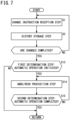
- FIG. 7 is a flowchart illustrating a process flow of the control method according to the second embodiment.
- the control device 14' is capable of executing the control method shown in FIG. 7 .
- the control method shown in FIG. 7 includes the change instruction reception step S1, the history storage step S2, a first determination step S13, an Undo/Redo prohibition step S14, and a second determination step S15.
- the change instruction reception step S1 and the history storage step S2 have already been described in relation to the first embodiment. Accordingly, description of the change instruction reception step S1 and the history storage step S2 is omitted.
- the determination unit 68 determines whether or not the automatic operation has been initiated. In this instance, in the case it is determined that the automatic operation has been initiated (step S13: YES), the Undo/Redo prohibition step S14 is executed. On the other hand, in the case it is determined that the automatic operation has not been initiated (step S13: NO), the control method of the present embodiment is immediately terminated (RETURN).
- the Undo/Redo prohibition unit 76 prohibits the Undo/Redo processing unit 66 from executing the Undo/Redo process.
- the determination unit 68 determines whether or not the automatic operation has been completed. In this instance, when it is determined that the automatic operation has been completed (step S15: YES), the control method of the present embodiment comes to an end (RETURN). On the other hand, if it is determined that the automatic operation has not been completed (step S15: NO), the Undo/Redo prohibition step S14 is continued.
- control device 14' may further be equipped with the history deletion control unit 70 (refer to the first embodiment).
- the history deletion control unit 70 deletes the change history 56 from the start until the end of the automatic operation.
- the period from the start until the end of the automatic operation contains the time point of completion of the automatic operation.
- the timing at which the predetermined condition is satisfied is not particularly limited, insofar as it is within a period from the start until the end of the automatic operation. More specifically, the timing at which the change history 56 is deleted is not particularly limited, insofar as it is within a period from the start until the end of the automatic operation.
- the History deletion control unit 70 deletes the change history 56, any concern over erroneously setting the machining program 52 and the control parameters 54 is reduced.
- the Undo/Redo prohibition unit 76 prohibits the Undo/Redo process during the automatic operation.
- the change history 56 created before the initiation of the automatic operation is not deleted.
- the machining program 52 and the control parameters 54 may be erroneously set by an Undo/Redo process instruction unintended by the operator. Concerning this point, the history deletion control unit 70 deletes the change history 56 related to the automatic operation for the first time. In accordance with this feature, during the setup process for the second-time machining, any concern over the machining program 52 and the control parameters 54 being erroneously set is reduced.
- the control device (14) which controls the machine tool (12) that machines the workpiece (W) on the basis of the control parameters (54) and the machining program (52), to thereby cause the machine tool to carry out the automatic operation, includes the change instruction reception unit (62) that receives the change instruction made by the operator to change the control parameters and the machining program, the history storage control unit (64) that causes the change history (56) of the control parameters and the machining program to be stored in the storage unit (48) by cumulatively storing the change instructions made by the operator in the storage unit, the Undo/Redo processing unit (66) that performs the Undo/Redo process based on the change history, in accordance with the instruction made by the operator, the determination unit (68) that determines whether or not the predetermined condition for preventing the machine tool from operating in a manner unintended by the operator in accordance with the execution of the Undo/Redo process has been satisfied, and the history deletion control unit (70) that deletes the change history stored in the storage unit, in the case that the determination unit has determined
- control device that prevents the Undo/Redo process unintended by the operator from being executed.
- the determination unit may determine that the predetermined condition has been satisfied when the machine tool has initiated the automatic operation.
- the determination unit may periodically determine whether or not the machining by the automatic operation has been completed, and each time it is determined that the machining by the automatic operation is not completed, the determination unit may determine that the predetermined condition has been satisfied. In accordance with this feature, during the automatic operation, while allowing the change instruction intended by the operator, it is possible to prevent the Undo/Redo process unintended by the operator from being executed.
- the determination unit may determine that the predetermined condition has been satisfied, in the case that the automatic operation is paused. In accordance with this feature, execution of the Undo/Redo process unintended by the operator can be prevented more satisfactorily.
- the history storage control unit may not allow the change instruction made by the operator to be stored in the storage unit during the period from when the automatic operation is initiated until after the machining is completed.
- the change instruction intended by the operator it is possible to prevent the Undo/Redo process unintended by the operator from being executed.
- the determination unit may determine that the predetermined condition has been satisfied.
- the machining program and the control parameters which have been used in an immediately prior automatic operation are prevented from being set.
- the first invention may further be equipped with the display control unit (60) that displays on the display unit (44) the setting change screen (72) in order for the operator to change at least one of the control parameters or the machining program, wherein the determination unit may determine that the predetermined condition has been satisfied when a screen transition from the setting change screen to another screen is performed by the display control unit.
- the control parameters and the machining program that were changed on the setting change screen are prevented from being unintentionally changed after the screen transition from the setting change screen has taken place.
- the control device (14') which controls the machine tool (12') that machines the workpiece (W) on the basis of the control parameters (54) and the machining program (52), to thereby cause the machine tool to carry out the automatic operation includes the change instruction reception unit (62) that receives the change instruction made by the operator to change the control parameters and the machining program, the history storage control unit (64) that causes the change history (56) of the control parameters and the machining program to be stored in the storage unit (48) by cumulatively storing the change instructions made by the operator in the storage unit, the Undo/Redo processing unit (66) that performs the Undo/Redo process based on the change history, in accordance with the instruction made by the operator, and the Undo/Redo prohibition unit (76) that prohibits the Undo/Redo processing unit from performing the Undo/Redo process from a start until an end of the automatic operation.
- the change instruction reception unit (62) that receives the change instruction made by the operator to change the control parameters and the machining program
- control device that prevents the Undo/Redo process from being executed unintentionally by the operator.
- the second invention may further include the determination unit (68) that determines whether or not the predetermined condition for preventing the machine tool from operating in a manner unintended by the operator in accordance with the execution of the Undo/Redo process has been satisfied, and the history deletion control unit (70) that deletes the change history stored in the storage unit, in the case that the determination unit has determined that the predetermined condition has been satisfied.
- the determination unit (68) determines whether or not the predetermined condition for preventing the machine tool from operating in a manner unintended by the operator in accordance with the execution of the Undo/Redo process has been satisfied
- the history deletion control unit (70) that deletes the change history stored in the storage unit, in the case that the determination unit has determined that the predetermined condition has been satisfied.
- the determination unit according to the second invention may determine that the predetermined condition has been satisfied when the machine tool has initiated the automatic operation.
- the determination unit may periodically determine whether or not the machining by the automatic operation has been completed, and each time it is determined that the machining by the automatic operation is not completed, the determination unit may determine that the predetermined condition has been satisfied.
- the determination unit may determine that the predetermined condition has been satisfied.
- the determination unit according to the second invention may determine that the predetermined condition has been satisfied, in the case that the automatic operation is paused. In accordance with this feature, execution of the Undo/Redo process unintended by the operator can be prevented more satisfactorily.
- the machine tool system (10, 10') includes the control device (14, 14') of the first invention or the second invention, and the machine tool (12) that carries out the automatic operation by being controlled by the control device.
- the machine tool system is provided that prevents the Undo/Redo process unintended by the operator from being executed.
- the machine tool may be a wire electrical discharge machine.
- the control method of controlling the machine tool (12) that machines the workpiece (W) on the basis of the control parameters (54) and the machining program (52), to thereby cause the machine tool to carry out the automatic operation includes the change instruction reception step (S1) of receiving the change instruction made by the operator to change the control parameters and the machining program, the history storage step (S2) of causing the change history (56) of the control parameters and the machining program to be stored in the storage unit (48) by cumulatively storing the change instructions made by the operator in the storage unit, in a manner so that the Undo/Redo process of the change instruction by the operator can be carried out, the determination step (S3) of determining whether or not the predetermined condition for preventing the machine tool (12) from operating in a manner unintended by the operator in accordance with the execution of the Undo/Redo process has been satisfied, and the history deletion control step (S4) of deleting the change history stored in the storage unit, in the case it is determined in the determination step that the predetermined condition has been satisfied.
- control method that prevents the Undo/Redo process unintended by the operator from being executed.
Landscapes
- Engineering & Computer Science (AREA)
- Human Computer Interaction (AREA)
- Manufacturing & Machinery (AREA)
- Physics & Mathematics (AREA)
- General Physics & Mathematics (AREA)
- Automation & Control Theory (AREA)
- Chemical & Material Sciences (AREA)
- Chemical Kinetics & Catalysis (AREA)
- Electrochemistry (AREA)
- Mechanical Engineering (AREA)
- Electrical Discharge Machining, Electrochemical Machining, And Combined Machining (AREA)
- Numerical Control (AREA)
Abstract
Description
- The present invention relates to a control device configured to control a machine tool, a machine tool system including the control device, and a control method for controlling the machine tool.
- In
JP 2020-061017 A JP 2020-061017 A JP 2020-061017 A - The machine tool carries out machining on the basis of the control parameters and the machining program. The control parameters and the machining program are stored in a control device for controlling the machine tool. In this case, the machine tool is capable of executing machining by way of an automatic operation. In this instance, for example, during a setup process prior to initiating the automatic operation, or after the automatic operation has been initiated, concerning the control parameters and the machining program, there may be a case in which the Undo/Redo process that is not intended by the operator is executed accidentally. In this case, during the automatic operation, the machine tool performs an operation that is unintended by the operator.
- Thus, the present invention has the object of providing a control device, a machine tool system, and a control method which are capable of preventing execution of an Undo/Redo process that is not intended by the operator.
- A first aspect of the present invention is characterized by a control device that controls, based on a control parameter and a machining program, a machine tool configured to machine a workpiece, to thereby cause the machine tool to carry out an automatic operation, the control device including a change instruction reception unit configured to receive a change instruction made by an operator to change the control parameter and the machining program, a history storage control unit configured to cause a change history of the control parameter and the machining program to be stored in a storage unit by cumulatively storing the change instruction made by the operator in the storage unit, an Undo/Redo processing unit configured to perform an Undo/Redo process based on the change history, in accordance with an instruction made by the operator, a determination unit configured to determine whether or not a predetermined condition for preventing the machine tool from operating in a manner unintended by the operator in accordance with execution of the Undo/Redo process has been satisfied, and a history deletion control unit configured to delete the change history stored in the storage unit, in a case that the determination unit has determined that the predetermined condition has been satisfied.
- A second aspect of the present invention is characterized by a control device that controls, based on a control parameter and a machining program, a machine tool configured to machine a workpiece, to thereby cause the machine tool to carry out an automatic operation, the control device including a change instruction reception unit configured to receive a change instruction made by an operator to change the control parameter and the machining program, a history storage control unit configured to cause a change history of the control parameter and the machining program to be stored in a storage unit by cumulatively storing the change instruction made by the operator in the storage unit, an Undo/Redo processing unit configured to perform an Undo/Redo process based on the change history, in accordance with an instruction made by the operator, and an Undo/Redo prohibition unit configured to prohibit the Undo/Redo processing unit from performing the Undo/Redo process from a start until an end of the automatic operation.
- A third aspect of the present invention is characterized by a machine tool system, including the control device of the first aspect or the second aspect, and the machine tool configured to carry out the automatic operation by being controlled by the control device.
- A fourth aspect of the present invention is characterized by a control method of controlling, based on a control parameter and a machining program, a machine tool configured to machine a workpiece, to thereby cause the machine tool to carry out an automatic operation, the control method including a change instruction reception step of receiving a change instruction made by an operator to change the control parameter and the machining program, a history storage step of causing a change history of the control parameter and the machining program to be stored in a storage unit by cumulatively storing the change instruction made by the operator in the storage unit, in a manner so that an Undo/Redo process of the change instruction is able to be carried out, a determination step of determining whether or not a predetermined condition for preventing the machine tool from operating in a manner unintended by the operator in accordance with execution of the Undo/Redo process has been satisfied, and a history deletion control step of deleting the change history stored in the storage unit, in a case it is determined in the determination step that the predetermined condition has been satisfied.
- According to the aspects of the present invention, the control device, the machine tool system, and the control method are provided, which are capable of preventing execution of an Undo/Redo process that is not intended by the operator.
-
-
FIG. 1 is an overall configuration view of a machine tool system according to a first embodiment; -
FIG. 2A is a schematic diagram showing a first example of a setting change screen displayed on a display unit according to the first embodiment; -
FIG. 2B is a schematic diagram showing a second example of the setting change screen displayed on the display unit according to the first embodiment; -
FIG. 3 is a flowchart illustrating a process flow of a control method according to the first embodiment; -
FIG. 4 is a flowchart illustrating a process flow of a first example of the control method according to a first exemplary modification; -
FIG. 5 is a flowchart illustrating a process flow of a second example of the control method according to the first exemplary modification; -
FIG. 6 is a schematic configuration diagram of a machine tool system according to a second embodiment; and -
FIG. 7 is a flowchart illustrating a process flow of a control method according to the second embodiment. - A description will be presented in detail below with reference to the accompanying drawings which set forth suitable embodiments concerning a control device, a machine tool system, and a control method according to the present invention.
-
FIG. 1 is an overall configuration view of amachine tool system 10 according to a first embodiment. Among the plurality of axial directions shown inFIG. 1 , the X-axis and the Y-axis are axial directions that are parallel to a horizontal plane. The Z-axis is an axial direction that is parallel to the direction of gravity. The X-axis, the Y-axis, and the Z-axis are perpendicular to each other. Further, the U-axis inFIG. 1 is an axial direction lying parallel to the X-axis. The V-axis is an axial direction lying parallel to the Y-axis. - The
machine tool system 10 according to the present embodiment is equipped with amachine tool 12 and a control device 14 (refer toFIG. 1 ). Themachine tool 12 according to the present embodiment is a wire electrical discharge machine. Accordingly, hereinafter, themachine tool 12 may also be referred to as a wireelectrical discharge machine 12. However, the wireelectrical discharge machine 12 is illustrated as an example. Accordingly, the type of themachine tool 12 is not limited to being a wire electrical discharge machine. - The wire
electrical discharge machine 12 is themachine tool 12 that carries out electrical discharge machining on a workpiece (an object to be machined) W by using an electric discharge generated in an inter-electrode gap g between awire electrode 16 and the workpiece W. The wireelectrical discharge machine 12 is equipped with a table 18, an upper-side guide 20, a lower-side guide 22, and an electrical power source 24 (refer toFIG. 1 ). - The table 18 serves as a support platform that supports the workpiece W. The upper-
side guide 20 is a wire guide that guides thewire electrode 16 above the table 18 in the Z direction. The lower-side guide 22 is a wire guide that guides thewire electrode 16 below the table 18 in the Z direction. Thewire electrode 16 is extended under tension between the upper-side guide 20 and the lower-side guide 22. Consequently, thewire electrode 16 forms the inter-electrode gap g together with the workpiece W. - The wire
electrical discharge machine 12 is further equipped with a wire feeding mechanism that causes thewire electrode 16 to travel along the Z direction. However, in the present embodiment, illustration of the wire feeding mechanism is omitted. The wire feeding mechanism includes, for example, a plurality of rollers and motors. In this instance, thewire electrode 16 is wound around each of the rollers. The motors control the rotational torques of the rollers respectively. - The
electrical power source 24 is an element for applying a voltage to each of thewire electrode 16 and the workpiece W. For example, theelectrical power source 24 includes an electrical circuit that is capable of generating voltage pulses. The aforementioned discharge is generated in the inter-electrode gap g in accordance with the voltage pulses of theelectrical power source 24. - The wire
electrical discharge machine 12 is further equipped with atable movement mechanism 26, an upper-sideguide movement mechanism 28, and a lower-sideguide movement mechanism 30. - The
table movement mechanism 26 is a mechanism that causes the table 18 to be moved along each of the X direction and the Y direction. Thetable movement mechanism 26, for example, includes anX-axis motor 32 and a Y-axis motor 34. TheX-axis motor 32 is a drive source that causes the table 18 to be moved along the X direction. The Y-axis motor 34 is a drive source that causes the table 18 to be moved along the Y direction. By the table 18 being made to move in a horizontal direction, relative movement in relation to the horizontal direction between the workpiece W on the table 18 and thewire electrode 16 is realized. - The upper-side
guide movement mechanism 28 is a mechanism that causes the upper-side guide 20 to be moved along each of the U direction and the V direction. The upper-sideguide movement mechanism 28 includes, for example, aU-axis motor 36UPPER and a V-axis motor 38UPPER. TheU-axis motor 36UPPER is a drive source for causing the upper-side guide 20 to be moved along the U direction. The V-axis motor 38UPPER is a drive source for causing the upper-side guide 20 to be moved along the V direction. The lower-sideguide movement mechanism 30 is a mechanism that causes the lower-side guide 22 to be moved along each of the U direction and the V direction. The lower-sideguide movement mechanism 30 includes, for example, aU-axis motor 40LOWER and a V-axis motor 42LOWER. TheU-axis motor 40LOWER is a drive source for causing the lower-side guide 22 to be moved along the U direction. The V-axis motor 42LOWER is a drive source for causing the lower-side guide 22 to be moved along the V direction. The upper-sideguide movement mechanism 28 and the lower-sideguide movement mechanism 30 are capable of causing the position of the upper-side guide 20 and the positon of the lower-side guide 22 in the horizontal direction to coincide with each other. In accordance with this feature, thewire electrode 16 becomes parallel with the Z-axis between the upper-side guide 20 and the lower-side guide 22. Further, the upper-sideguide movement mechanism 28 and the lower-sideguide movement mechanism 30 are also capable of causing the position of the upper-side guide 20 and the position of the lower-side guide 22 in the horizontal direction to differ from each other. In accordance with this feature, thewire electrode 16 becomes inclined with respect to the Z-axis between the upper-side guide 20 and the lower-side guide 22. - The wire
electrical discharge machine 12 described above causes an electric discharge to be generated in the inter-electrode gap g while causing thewire electrode 16 to be moved relatively with respect to the workpiece W. Consequently, the wireelectrical discharge machine 12 machines the workpiece W into a shape along a path (machining path) of relative movement of thewire electrode 16. Further, the wireelectrical discharge machine 12 is capable of easily adjusting the angle of inclination of thewire electrode 16 with respect to the Z-axis, as described above. Accordingly, the wireelectrical discharge machine 12 is capable of easily implementing a so-called taper cutting. - The
control device 14 is an electronic device which, by controlling the wireelectrical discharge machine 12, causes the wireelectrical discharge machine 12 to carry out an automatic operation. Thecontrol device 14 is equipped with adisplay unit 44, anoperation unit 46, astorage unit 48, and a computation unit 50 (refer toFIG. 1 ). - The
display unit 44 serves to display information. Thedisplay unit 44 includes, for example, a liquid crystal or an organic EL (OEL: Organic Electro-Luminescence) monitor. - The
operation unit 46 receives information that is input by the operator of themachine tool system 10. Theoperation unit 46 includes, for example, a keyboard, a mouse, and a touch panel. The touch panel is installed, for example, on the monitor of thedisplay unit 44. - The
storage unit 48 serves to store information. Thestorage unit 48 includes a memory. In this instance, the memory contains, for example, a RAM (Random Access Memory) and a ROM (Read Only Memory). Thestorage unit 48 of the present embodiment stores amachining program 52,control parameters 54, and achange history 56. Thechange history 56 is a history of changes made to themachining program 52 and thecontrol parameters 54. - The
machining program 52 is a predetermined program that defines the aforementioned machining path. The operator is capable of changing (editing) themachining program 52 via theoperation unit 46. The changed contents of themachining program 52 are cumulatively stored in thestorage unit 48 as part of thechange history 56 by a historystorage control unit 64. Moreover, it should be noted that the historystorage control unit 64 will be described later. - From among the information necessary for controlling the wire
electrical discharge machine 12, thecontrol parameters 54 refer to general information, other than the machining path, that can be specified by the operator. Thestorage unit 48 is capable of storing a plurality of types of the control parameters 54 (54A, 54B, ...) (refer toFIG. 1 ). The types of thecontrol parameters 54 include, for example, a pulse interval (pausing time period) of the voltage pulses, and a relative movement speed (feeding speed) of thewire electrode 16 with respect to the workpiece W. However, thecontrol parameters 54 are not limited to being the pausing time period and the feeding speed. For example, thecontrol parameters 54 may include information regarding a diameter (wire diameter) or a material of thewire electrode 16. Further, thecontrol parameters 54 may include information regarding a material or a plate thickness of the workpiece W. The operator is capable of changing thecontrol parameters 54 via theoperation unit 46. The changed contents of thecontrol parameters 54 are cumulatively stored in thestorage unit 48 as part of thechange history 56 by the historystorage control unit 64. - The
computation unit 50 performs a computation process on the information. Thecomputation unit 50 includes a processor. In this instance, the processor includes, for example, a CPU (Central Processing Unit) and a GPU (Graphics Processing Unit). Thecomputation unit 50 comprises anoperation control unit 58, adisplay control unit 60, a changeinstruction reception unit 62, a historystorage control unit 64, an Undo/Redo processing unit 66, adetermination unit 68, and a history deletion control unit 70 (refer toFIG. 1 ). Theoperation control unit 58, thedisplay control unit 60, the changeinstruction reception unit 62, the historystorage control unit 64, the Undo/Redo processing unit 66, thedetermination unit 68, and the historydeletion control unit 70 are virtually realized by thecomputation unit 50 executing a predetermined control program. In this instance, the predetermined control program is stored beforehand in thestorage unit 48 in a manner so that thecomputation unit 50 is capable of reading the control program (not shown). - The
operation control unit 58 causes the wireelectrical discharge machine 12 to perform the automatic operation, by controlling the wireelectrical discharge machine 12 on the basis of themachining program 52 and thecontrol parameters 54. For example, in the case that an instruction is issued by the operator via theoperation unit 46 to initiate the automatic operation, theoperation control unit 58 refers to themachining program 52 and thecontrol parameters 54 that are stored in thestorage unit 48. Theoperation control unit 58 initiates the automatic operation of the wireelectrical discharge machine 12 on the basis of the referencedmachining program 52 andcontrol parameters 54. In such an automatic operation, theoperation control unit 58 automatically controls the pausing time period, for example, based on thecontrol parameters 54 related to theelectrical power source 24. Further, theoperation control unit 58 automatically controls the relative movement of the wire electrode 16 (the table movement mechanism 26) based on themachining program 52. - The
display control unit 60 causes the display unit (monitor) 44 to display setting change screens 72 (refer toFIGS. 2A and 2B ). The settingchange screens 72 are screens in order for the operator to change at least one of themachining program 52 or thecontrol parameters 54. The changeinstruction reception unit 62 also receives a change instruction to change themachining program 52 and thecontrol parameters 54, based on an operation of theoperation unit 46 made by the operator. In accordance with this feature, while observing the setting change screens 72, the operator is capable of transmitting the change instruction to the changeinstruction reception unit 62. Based on the change instruction made by the operator, the changeinstruction reception unit 62 changes (updates) themachining program 52 and thecontrol parameters 54. -
FIG. 2A is a schematic diagram showing a first example of the settingchange screens 72 displayed on thedisplay unit 44 according to the first embodiment.FIG. 2B is a schematic diagram showing a second example of the settingchange screens 72 displayed on thedisplay unit 44 according to the first embodiment. - The setting
change screens 72 include, for example, a settingchange screen 72A (refer toFIG. 2A ) and a settingchange screen 72B (refer toFIG. 2B ). It should be noted that the user interface of the settingchange screen 72A is not limited to the example illustrated inFIG. 2A . Further, the user interface of the settingchange screen 72B is not limited to the example illustrated inFIG. 2B . - The setting
change screen 72A is displayed on thedisplay unit 44 in the case that the operator changes thecontrol parameters 54. In this instance, thedisplay control unit 60 causes thedisplay unit 44 to display the settingchange screen 72A. A plurality of items for designating thecontrol parameters 54 are displayed on the settingchange screen 72A. In this instance, the plurality of items include, for example, an item for specifying the pausing time period, and an item for specifying the feeding speed. While observing the settingchange screen 72A, the operator is capable of specifying thecontrol parameters 54 corresponding to each of the items via theoperation unit 46. Designation of thecontrol parameters 54 in this context includes an operation of changing thecontrol parameters 54 that have already been designated by the operator. - The setting
change screen 72B is displayed on thedisplay unit 44 in the case that the operator changes (edits) themachining program 52. In this instance, thedisplay control unit 60 causes thedisplay unit 44 to display the settingchange screen 72B. The contents of themachining program 52 are displayed on the settingchange screen 72B. More specifically, the settingchange screen 72B displays codes representing the machining path. While observing the settingchange screen 72B, the operator is capable of performing an operation to change (edit) themachining program 52 via theoperation unit 46. - The setting change screens 72 (72A and 72B) each include two icons 74 (74UNDO and 74REDO). The two
icons 74 are displayed in common on both the settingchange screen 72A and the settingchange screen 72B. Theicon 74UNDO is anicon 74 in order for the operator to issue an Undo process instruction. The operator can issue an instruction to thecontrol device 14 to execute the Undo process by clicking on theicon 74UNDO with a mouse, or alternatively, by touching the touch panel. Further, theicon 74REDO is anicon 74 in order for the operator to issue a Redo process instruction. The operator can issue an instruction to thecontrol device 14 to execute the Redo process by clicking on theicon 74REDO with a mouse, or alternatively, by touching the touch panel. - In this instance, a description is given concerning the Undo/Redo process. However, since the Undo/Redo process is already known, the operation will be briefly explained. The "Undo/Redo" process refers to a process that includes two types of processing, including the "Undo" process and the "Redo" process. The Undo process is a process for canceling the change instruction. When the Undo process is executed, the
machining program 52 or thecontrol parameters 54 are returned to the state prior to the change instruction having been issued. When the Undo process is executed consecutively, the change instruction to change themachining program 52 or thecontrol parameters 54 is canceled for the number of times that the Undo process was carried out. On the other hand, the Redo process is a process of canceling the aforementioned Undo process. When the Redo process is executed after the Undo process has been executed, themachining program 52 or thecontrol parameters 54 are returned to the state prior to the Undo process having been executed. Further, when the Redo process is executed consecutively, the execution of the Undo process is canceled for the number of times that the execution was carried out. - In order for the
control device 14 to execute the Undo/Redo process, a cumulative record of the past change instructions made by the operator is required. According to the present embodiment, the historystorage control unit 64 causes thechange history 56 to be stored in thestorage unit 48. More specifically, by cumulatively causing the change instructions made by the operator to be stored in thestorage unit 48, the historystorage control unit 64 causes thechange history 56 of the changes made to thecontrol parameters 54 and themachining program 52 to be stored in thestorage unit 48. - The Undo/
Redo processing unit 66 performs an Undo/Redo process in the present embodiment. The Undo/Redo processing unit 66 executes the Undo process when the operator presses theicon 74UNDO. In this instance, the Undo/Redo processing unit 66 refers to thechange history 56 as necessary. Further, the Undo/Redo processing unit 66 executes the Redo process when the operator presses theicon 74REDO. In this instance as well, the Undo/Redo processing unit 66 refers to thechange history 56 as necessary. - The
determination unit 68 determines whether or not a predetermined condition has been satisfied. In this instance, the predetermined condition is a condition determined in order to prevent the wireelectrical discharge machine 12 from operating in a manner unintended by the operator due to execution of the Undo/Redo process. In the case that thedetermination unit 68 has determined that the predetermined condition has been satisfied, the historydeletion control unit 70 deletes thechange history 56 that was stored in thestorage unit 48. - The predetermined condition designates a start timing of the period during which the execution of the Undo/Redo process is prohibited. The
change history 56 is deleted when the predetermined condition has been satisfied. Accordingly, the Undo/Redo processing unit 66 is not capable of referring to thechange history 56 after the predetermined condition has been satisfied. Therefore, execution of the Undo/Redo process by the Undo/Redo processing unit 66 is substantially prohibited after the predetermined condition has been satisfied. As a result, after the predetermined condition has been satisfied, an execution of the Undo/Redo process that is not intended by the operator is prevented. Accordingly, any concern that the wireelectrical discharge machine 12 may operate in a manner that is unintended by the operator is reduced. - Hereinafter, a specific example of the predetermined condition will be described. If the Undo/Redo process is executed during a period from the initiation of machining by the automatic operation until after the machining is completed, the wire
electrical discharge machine 12 may operate in a manner that is unintended by the operator. Taking this into consideration, the predetermined condition, for example, is "the initiation of the automatic operation of the wireelectrical discharge machine 12". In this case, thedetermination unit 68 determines that the predetermined condition has been satisfied in the case that the wireelectrical discharge machine 12 has initiated the automatic operation. Further, in the case that the wireelectrical discharge machine 12 has initiated the automatic operation, the historydeletion control unit 70 deletes thechange history 56 that is stored in thestorage unit 48. Consequently, execution of the Undo/Redo process during the automatic operation is substantially prohibited. -
FIG. 3 is a flowchart illustrating a process flow of the control method according to the first embodiment. - Hereinafter, a description will be given concerning the control method shown in
FIG. 3 . Thecontrol device 14 is capable of executing the control method shown inFIG. 3 . The control method shown inFIG. 3 includes a change instruction reception step S1, a history storage step S2, a determination step S3, and a history deletion control step S4. - The change instruction reception step S1 and the history storage step S2 are included in a preparatory process (a so-called "setup" process) performed by the operator. The setup process is performed prior to the wire
electrical discharge machine 12 initiating the automatic operation. In the change instruction reception step S1, the changeinstruction reception unit 62 receives an instruction by the operator to change thecontrol parameters 54 and themachining program 52. In this instance, in the case that the history storage step S2 has already been performed one time or more (to be described later), thechange history 56 has already been stored in thestorage unit 48. In this case, the operator may issue an instruction to the Undo/Redo processing unit 66 to execute the Undo/Redo process as necessary. - In the history storage step S2, the history
storage control unit 64 causes thechange history 56 to be stored in thestorage unit 48. In accordance with this feature, the Undo/Redo processing unit 66 is capable of performing the Undo/Redo process in accordance with the instruction made by the operator. - The change instruction reception step S1 and the history storage step S2 may be carried out repeatedly until the setting operation of the
control parameters 54 and themachining program 52 is completed ("Are Changes Completed?": YES inFIG. 3 ) (refer toFIG. 3 ). - In the determination step S3, the
determination unit 68 determines whether or not the wireelectrical discharge machine 12 has initiated the automatic operation (whether or not the predetermined condition has been satisfied). In this instance, in the case it is determined that the automatic operation has been initiated (step S3: YES), the history deletion control step S4 is executed. On the other hand, in the case it is determined that the automatic operation has not been initiated (step S3: NO), the control method of the present embodiment is immediately terminated (RETURN). - In the history deletion control step S4, the history
deletion control unit 70 deletes thechange history 56 that is stored in thestorage unit 48. In accordance with this feature, at a time after the history deletion control step S4, execution of the Undo/Redo process in a manner unintended by the operator is prevented. As noted previously, according to the present embodiment, the history deletion control step S4 is executed at the time when the automatic operation is initiated. - As noted previously, according to the present embodiment, by suppressing the execution of the Undo/Redo process that is not intended by the operator, the
control device 14 reduces the occurrence in which themachine tool 12, which is currently performing the automatic operation, is operated in a manner unintended by the operator. Further, themachine tool system 10 that includes such acontrol device 14 is provided. Further, the control method that is executed by thecontrol device 14 is provided. - The first embodiment has been described above as one example of the present invention. Various modifications or improvements are capable of being added to the first embodiment. Further, it is clear from the scope of the claims that other modes to which such modifications or improvements have been added can be included within the technical scope of the present invention.
- Hereinafter, a description will be given the concerning exemplary modifications of the first embodiment. However, explanations that overlap with those of the first embodiment will be omitted insofar as possible in the following description. Unless otherwise specified, reference numerals of constituent components that have already been described in the first embodiment are used from the first embodiment.
- The predetermined condition is not limited to being the condition that "automatic operation of the
machine tool 12 has been initiated" (first embodiment). - For example, after initiation of the machining by the automatic operation, the
determination unit 68 may periodically determine whether or not the machining has been completed. In this case, when it is determined that the machining by the automatic operation has not been completed, thedetermination unit 68 may determine that the predetermined condition has been satisfied. In this case, each time it is determined that the predetermined condition has been satisfied, the historydeletion control unit 70 deletes thechange history 56. That is, at a time during execution of the machining by the automatic operation, the historydeletion control unit 70 periodically deletes thechange history 56. A designer or the operator of themachine tool system 10 may examine and decide in advance the time period interval at which thedetermination unit 68 performs the determination. - According to the present exemplary modification, during the automatic operation, while allowing the change instruction intended by the operator, the Undo/Redo process unintended by the operator is prevented from being executed. In other words, the
control device 14 according to the first embodiment prevents the Undo/Redo process from being executed after initiation of the automatic operation. However, for example, at a time after initiation of the automatic operation, a case may occur in which a setting error is noticed by the operator. When such a case is considered, it is preferable to allow the operator to intentionally change themachining program 52 and thecontrol parameters 54 during the automatic operation. However, in such a case, thechange history 56 is newly stored in thestorage unit 48 based on the change instruction made by the operator after initiation of the automatic operation. Consequently, it is made possible for thecontrol device 14 to execute the Undo/Redo process again. In this instance, the historydeletion control unit 70 according to the present exemplary modification periodically deletes thechange history 56 in the case that themachine tool system 10 is currently executing the automatic operation. The time period interval during which the deletion process is repeated is preferably as short as possible, in a manner so that the Undo/Redo process is not executed. In accordance with this feature, during the automatic operation, while allowing the change instruction intended by the operator, thecontrol device 14 prevents the Undo/Redo process that is not intended by the operator from being executed. - Moreover, there may be cases in which the
machine tool system 10 pauses (temporarily stops) the automatic operation. Themachine tool system 10 pauses the automatic operation, for example, due to the following reasons (1) to (4): (1) a case in which themachine tool system 10 executes a program that includes pausing of the automatic operation; (2) a case in which an alarm is issued during machining; (3) a case in which a stop instruction is issued by the operator; and (4) a case in which thewire electrode 16 is disconnected. In a situation where the automatic operation is paused, although the automatic operation control is suspended, a condition occurs in which the machining is not yet completed. Accordingly, except in the case that the operator intentionally issues the change instruction, it is undesirable for thecontrol parameters 54 and themachining program 52 to be changed during the period in which the automatic operation is paused. For the aforementioned reason, it is preferable that thedetermination unit 68 determines that the predetermined condition is being satisfied, even in the case that the automatic operation is paused. Consequently, the historydeletion control unit 70 deletes thechange history 56 even during the period in which the automatic operation is being paused. As a result, execution of the Undo/Redo process not intended by the operator is prevented more satisfactorily. The determination as to whether or not the automatic operation is being paused may be performed periodically. -
FIG. 4 is a flowchart illustrating a process flow of a first example of the control method according to the first exemplary modification. - The
determination unit 68 according to the above-described example determines whether or not the machining is completed after the automatic operation has been initiated (step S3' inFIG. 4 ). In this instance, in the case that the automatic operation is paused, thedetermination unit 68 preferably determines that the machining has not been completed. In the case it is determined that the machining has not been completed (S3': NO), the historydeletion control unit 70 deletes the change history 56 (step S4' inFIG. 4 ). On the other hand, in the case it is determined that the machining is completed (step S3': YES), the control method comes to an end (RETURN). - Further, as another example of the present exemplary modification, the history
storage control unit 64 need not necessarily store the change instruction in thestorage unit 48 during the period from when the automatic operation is initiated until after the machining is completed. In accordance with this feature, during the automatic operation, while allowing the change instruction intended by the operator, the Undo/Redo process that is not intended by the operator is prevented from being executed. In other words, as noted previously, it is preferable to allow the operator to intentionally change themachining program 52 and thecontrol parameters 54 during the automatic operation. However, if thechange history 56 is stored in thestorage unit 48 based on the change instruction made by the operator, execution of the Undo/Redo process cannot be prevented thereafter. Thus, the historystorage control unit 64 does not allow thestorage unit 48 to store thechange history 56 concerning the change instruction issued during a period from when the automatic operation is initiated until after the machining is completed. In accordance with this feature, during the automatic operation, while allowing the change instruction intended by the operator, it is possible for thecontrol device 14 according to the present exemplary modification to prevent the Undo/Redo process unintended by the operator from being executed. -
FIG. 5 is a flowchart illustrating a process flow of a second example of the control method according to the first exemplary modification. - After having initiated the automatic operation, the history
storage control unit 64 according to the above-described example does not cumulatively store the change instructions made by the operator until the machining is completed (step S5 inFIG. 5 ). Thedetermination unit 68 determines whether or not the machining is completed after the automatic operation has been initiated (step S6 inFIG. 5 ). In this instance, in the case it is determined that the machining is completed (step S6: YES), storage of the change instruction is permitted (step S7 inFIG. 5 ). Thereafter, in the case that a change instruction is issued, the historystorage control unit 64 updates thechange history 56 based on the change instruction. On the other hand, in the case it is determined that the machining has not been completed (step S6: NO), storage of the change instruction is continuously prohibited. - In the example shown in
FIG. 5 , the timing at which thechange history 56 is deleted (step S4" inFIG. 5 ) is at a time when the automatic operation is initiated. Consequently, the Undo/Redo process is prevented from being executed during the automatic operation. Moreover, in the example shown inFIG. 5 , thechange history 56 may be periodically deleted, similar to the example shown inFIG. 4 . - The
determination unit 68 may determine that the predetermined condition has been satisfied, in the case that the machining by the automatic operation has been completed. In this case, the historydeletion control unit 70 deletes thechange history 56 in the case that the machining by the automatic operation has been completed. - The
machine tool system 10 may carry out the machining for a second time after the machining for the first time has been completed. In this instance, themachining program 52 and thecontrol parameters 54 may differ between the machining for the first time and the machining for the second time. In this case, the operator performs a setup process for the second-time machining after the first-time machining has been completed. However, if the operator carelessly issues an instruction for the Undo/Redo process during the setup process for the second-time machining, there is a possibility that themachining program 52 and thecontrol parameters 54 used in the machining for the first time may be set in thecontrol device 14. In this case, a machining defect may occur during the machining for the second time. - Concerning this point, according to the present exemplary modification, the
change history 56 is deleted in the case that the machining by the automatic operation has been completed. Accordingly, in the case that the setting operation to set themachining program 52 and thecontrol parameters 54 is performed by the operator, themachining program 52 and thecontrol parameters 54 which have been used in an immediately prior automatic operation are prevented from being set in thecontrol device 14. - The
display control unit 60 may cause a plurality of screens to be displayed on thedisplay unit 44 in a manner of enabling a screen transition. In this instance, the plurality of screens include the setting change screens 72. In the case that a screen transition from the settingchange screen 72 to another screen has been carried out, thedetermination unit 68 determines that the predetermined condition has been satisfied. Further, in the case that a screen transition from the settingchange screen 72 to another screen has taken place, the historydeletion control unit 70 deletes thechange history 56. - According to the present exemplary modification, at a time after the screen transition from the setting
change screen 72 to another screen has been carried out, execution of the unintended Undo/Redo process based on thechange history 56 prior to the transition is prevented. For example, the operator changes thecontrol parameters 54 while observing the settingchange screen 72A (refer toFIG. 2A ). Thereafter, thedisplay control unit 60 causes the screen to transition from the settingchange screen 72A to the settingchange screen 72B (refer toFIG. 2B ). Thecontrol parameters 54 that have been changed by the operator on the settingchange screen 72A are not displayed on the settingchange screen 72B. In this instance, provisionally, it is assumed that thechange history 56 concerning thecontrol parameters 54 remains in thestorage unit 48 even after the screen transition to the settingchange screen 72B has been completed. In this case, if the operator carelessly issues an instruction for the Undo/Redo process on the settingchange screen 72B, thecontrol parameters 54 are changed. Since thecontrol parameters 54 are not displayed on the settingchange screen 72B, it becomes difficult for the operator to realize that the operator has unintentionally changed thecontrol parameters 54. Concerning this point, according to the present exemplary modification, thechange history 56 is deleted in the case that a screen transition from the settingchange screen 72A to the other screen (72B) is performed. Consequently, on the other screen to which the screen transition has been made, the Undo/Redo process of thecontrol parameters 54 that have been changed on the settingchange screen 72A is prevented from occurring. - The constituent elements of the wire electrical discharge machine (the machine tool) 12 are not limited to those constituent elements described in the first embodiment. For example, the
control device 14 may be equipped with a constituent element for automatically controlling the wire feeding mechanism (refer to the first embodiment) based on thecontrol parameters 54. - The exemplary modifications described above may be appropriately combined within a range in which no technical inconsistencies occur.
- Hereinafter, a machine tool system 10' according to a second embodiment will be described. However, explanations that overlap with those of the first embodiment will be omitted insofar as possible in the following description. Unless otherwise specified, reference numerals of constituent components that have already been described in the first embodiment are used from the first embodiment.
-
FIG. 6 is a schematic configuration diagram of the machine tool system 10' according to the second embodiment. - The machine tool system 10' according to the present embodiment includes the
machine tool 12 and a control device 14'. Themachine tool 12, for example, is the wire electrical discharge machine. - The control device 14' differs from the
control device 14 of the first embodiment (refer toFIG. 1 ), in that it includes an Undo/Redo prohibition unit 76 instead of the historydeletion control unit 70. Accordingly, hereinafter, the Undo/Redo prohibition unit 76 will primarily be described. - In the same manner as the
operation control unit 58 etc., the Undo/Redo prohibition unit 76 is virtually realized based on a program. The Undo/Redo prohibition unit 76 prohibits the Undo/Redo process from being carried out during a period from the start until the end of the automatic operation. The Undo/Redo prohibition unit 76 prohibits the Undo/Redo process by issuing an instruction to the Undo/Redo processing unit 66. Incidentally, the determination as to whether or not the current state is within the period from the start to the end of the automatic operation, for example, is carried out by thedetermination unit 68. Further, the completion of the aforementioned automatic operation does not imply that the automatic operation is paused, but rather that the scheduled machining by the automatic operation is completed. -
FIG. 7 is a flowchart illustrating a process flow of the control method according to the second embodiment. - The control device 14' is capable of executing the control method shown in
FIG. 7 . The control method shown inFIG. 7 includes the change instruction reception step S1, the history storage step S2, a first determination step S13, an Undo/Redo prohibition step S14, and a second determination step S15. It should be noted that the change instruction reception step S1 and the history storage step S2 have already been described in relation to the first embodiment. Accordingly, description of the change instruction reception step S1 and the history storage step S2 is omitted. - In the first determination step S13, the
determination unit 68 determines whether or not the automatic operation has been initiated. In this instance, in the case it is determined that the automatic operation has been initiated (step S13: YES), the Undo/Redo prohibition step S14 is executed. On the other hand, in the case it is determined that the automatic operation has not been initiated (step S13: NO), the control method of the present embodiment is immediately terminated (RETURN). - In the Undo/Redo prohibition step S14, the Undo/
Redo prohibition unit 76 prohibits the Undo/Redo processing unit 66 from executing the Undo/Redo process. In the second determination step S15, thedetermination unit 68 determines whether or not the automatic operation has been completed. In this instance, when it is determined that the automatic operation has been completed (step S15: YES), the control method of the present embodiment comes to an end (RETURN). On the other hand, if it is determined that the automatic operation has not been completed (step S15: NO), the Undo/Redo prohibition step S14 is continued. - According to the present embodiment, without deleting the
change history 56, an execution of the Undo/Redo process unintended by the operator is prevented during a period from the start until the end of the automatic operation. - Moreover, it should be noted that the control device 14' may further be equipped with the history deletion control unit 70 (refer to the first embodiment). In such a case, the history
deletion control unit 70 deletes thechange history 56 from the start until the end of the automatic operation. The period from the start until the end of the automatic operation contains the time point of completion of the automatic operation. The timing at which the predetermined condition is satisfied is not particularly limited, insofar as it is within a period from the start until the end of the automatic operation. More specifically, the timing at which thechange history 56 is deleted is not particularly limited, insofar as it is within a period from the start until the end of the automatic operation. - Since the history
deletion control unit 70 deletes thechange history 56, any concern over erroneously setting themachining program 52 and thecontrol parameters 54 is reduced. In other words, according to the present embodiment, the Undo/Redo prohibition unit 76 prohibits the Undo/Redo process during the automatic operation. However, thechange history 56 created before the initiation of the automatic operation is not deleted. In this case, at a time during the setup process for the second-time machining which is performed after the automatic operation for the first time is completed, themachining program 52 and thecontrol parameters 54 may be erroneously set by an Undo/Redo process instruction unintended by the operator. Concerning this point, the historydeletion control unit 70 deletes thechange history 56 related to the automatic operation for the first time. In accordance with this feature, during the setup process for the second-time machining, any concern over themachining program 52 and thecontrol parameters 54 being erroneously set is reduced. - Further, the exemplary modifications described above in relation to the first embodiment can be appropriately applied to the present embodiment, insofar as the exemplary modifications are within a range in which no Inconsistencies occur.
- The inventions that can be grasped from the above-described embodiments and the modifications thereof will be described below.
- The control device (14) which controls the machine tool (12) that machines the workpiece (W) on the basis of the control parameters (54) and the machining program (52), to thereby cause the machine tool to carry out the automatic operation, includes the change instruction reception unit (62) that receives the change instruction made by the operator to change the control parameters and the machining program, the history storage control unit (64) that causes the change history (56) of the control parameters and the machining program to be stored in the storage unit (48) by cumulatively storing the change instructions made by the operator in the storage unit, the Undo/Redo processing unit (66) that performs the Undo/Redo process based on the change history, in accordance with the instruction made by the operator, the determination unit (68) that determines whether or not the predetermined condition for preventing the machine tool from operating in a manner unintended by the operator in accordance with the execution of the Undo/Redo process has been satisfied, and the history deletion control unit (70) that deletes the change history stored in the storage unit, in the case that the determination unit has determined that the predetermined condition has been satisfied.
- In accordance with these features, the control device is provided that prevents the Undo/Redo process unintended by the operator from being executed.
- The determination unit may determine that the predetermined condition has been satisfied when the machine tool has initiated the automatic operation.
- After initiation of the automatic operation, the determination unit may periodically determine whether or not the machining by the automatic operation has been completed, and each time it is determined that the machining by the automatic operation is not completed, the determination unit may determine that the predetermined condition has been satisfied. In accordance with this feature, during the automatic operation, while allowing the change instruction intended by the operator, it is possible to prevent the Undo/Redo process unintended by the operator from being executed.
- The determination unit may determine that the predetermined condition has been satisfied, in the case that the automatic operation is paused. In accordance with this feature, execution of the Undo/Redo process unintended by the operator can be prevented more satisfactorily.
- The history storage control unit may not allow the change instruction made by the operator to be stored in the storage unit during the period from when the automatic operation is initiated until after the machining is completed. In accordance with this feature, during the automatic operation, while allowing the change instruction intended by the operator, it is possible to prevent the Undo/Redo process unintended by the operator from being executed.
- When the machining by the automatic operation has been completed, the determination unit may determine that the predetermined condition has been satisfied. In accordance with this feature, in the case that the setting operation to set the machining program and the control parameters is performed by the operator, the machining program and the control parameters which have been used in an immediately prior automatic operation are prevented from being set.
- The first invention may further be equipped with the display control unit (60) that displays on the display unit (44) the setting change screen (72) in order for the operator to change at least one of the control parameters or the machining program, wherein the determination unit may determine that the predetermined condition has been satisfied when a screen transition from the setting change screen to another screen is performed by the display control unit. In accordance with these features, the control parameters and the machining program that were changed on the setting change screen are prevented from being unintentionally changed after the screen transition from the setting change screen has taken place.
- The control device (14') which controls the machine tool (12') that machines the workpiece (W) on the basis of the control parameters (54) and the machining program (52), to thereby cause the machine tool to carry out the automatic operation, includes the change instruction reception unit (62) that receives the change instruction made by the operator to change the control parameters and the machining program, the history storage control unit (64) that causes the change history (56) of the control parameters and the machining program to be stored in the storage unit (48) by cumulatively storing the change instructions made by the operator in the storage unit, the Undo/Redo processing unit (66) that performs the Undo/Redo process based on the change history, in accordance with the instruction made by the operator, and the Undo/Redo prohibition unit (76) that prohibits the Undo/Redo processing unit from performing the Undo/Redo process from a start until an end of the automatic operation.
- In accordance with these features, the control device is provided that prevents the Undo/Redo process from being executed unintentionally by the operator.
- The second invention may further include the determination unit (68) that determines whether or not the predetermined condition for preventing the machine tool from operating in a manner unintended by the operator in accordance with the execution of the Undo/Redo process has been satisfied, and the history deletion control unit (70) that deletes the change history stored in the storage unit, in the case that the determination unit has determined that the predetermined condition has been satisfied. In accordance with these features, in the case that the setting operation to set the machining program and the control parameters is performed by the operator, the machining program and the control parameters which have been used in an immediately prior automatic operation are prevented from being set.
- The determination unit according to the second invention may determine that the predetermined condition has been satisfied when the machine tool has initiated the automatic operation.
- After initiation of the automatic operation, the determination unit according to the second invention may periodically determine whether or not the machining by the automatic operation has been completed, and each time it is determined that the machining by the automatic operation is not completed, the determination unit may determine that the predetermined condition has been satisfied. In accordance with this feature, during the automatic operation, while allowing the change instruction intended by the operator, it is possible to prevent the Undo/Redo process not intended by the operator from being executed.
- The determination unit according to the second invention may determine that the predetermined condition has been satisfied, in the case that the automatic operation is paused. In accordance with this feature, execution of the Undo/Redo process unintended by the operator can be prevented more satisfactorily.
- The machine tool system (10, 10') includes the control device (14, 14') of the first invention or the second invention, and the machine tool (12) that carries out the automatic operation by being controlled by the control device.
- In accordance with these features, the machine tool system is provided that prevents the Undo/Redo process unintended by the operator from being executed.
- The machine tool may be a wire electrical discharge machine.
- The control method of controlling the machine tool (12) that machines the workpiece (W) on the basis of the control parameters (54) and the machining program (52), to thereby cause the machine tool to carry out the automatic operation, includes the change instruction reception step (S1) of receiving the change instruction made by the operator to change the control parameters and the machining program, the history storage step (S2) of causing the change history (56) of the control parameters and the machining program to be stored in the storage unit (48) by cumulatively storing the change instructions made by the operator in the storage unit, in a manner so that the Undo/Redo process of the change instruction by the operator can be carried out, the determination step (S3) of determining whether or not the predetermined condition for preventing the machine tool (12) from operating in a manner unintended by the operator in accordance with the execution of the Undo/Redo process has been satisfied, and the history deletion control step (S4) of deleting the change history stored in the storage unit, in the case it is determined in the determination step that the predetermined condition has been satisfied.
- In accordance with these features, the control method is provided that prevents the Undo/Redo process unintended by the operator from being executed.
Claims (15)
- A control device (14) that controls, based on a control parameter (54) and a machining program (52), a machine tool (12) configured to machine a workpiece (W), to thereby cause the machine tool to carry out an automatic operation, the control device comprising:a change instruction reception unit (62) configured to receive a change instruction made by an operator to change the control parameter and the machining program;a history storage control unit (64) configured to cause a change history (56) of the control parameter and the machining program to be stored in a storage unit (48) by cumulatively storing the change instruction made by the operator in the storage unit;an Undo/Redo processing unit (66) configured to perform an Undo/Redo process based on the change history, in accordance with an instruction made by the operator;a determination unit (68) configured to determine whether or not a predetermined condition for preventing the machine tool from operating in a manner unintended by the operator in accordance with execution of the Undo/Redo process has been satisfied; anda history deletion control unit (70) configured to delete the change history stored in the storage unit, in a case that the determination unit has determined that the predetermined condition has been satisfied.
- The control device according to claim 1, wherein the determination unit determines that the predetermined condition has been satisfied when the machine tool has initiated the automatic operation.
- The control device according to claim 1 or 2, wherein, after initiation of the automatic operation, the determination unit periodically determines whether or not machining by the automatic operation has been completed, and each time it is determined that the machining by the automatic operation is not completed, the determination unit determines that the predetermined condition has been satisfied.
- The control device according to claim 3, wherein the determination unit determines that the predetermined condition has been satisfied, in a case that the automatic operation is paused.
- The control device according to any one of claims 1 to 4, wherein the history storage control unit does not allow the change instruction made by the operator to be stored in the storage unit during a period from when the automatic operation is initiated until after machining is completed.
- The control device according to any one of claims 1 to 5, wherein the determination unit determines that the predetermined condition has been satisfied when machining by the automatic operation has been completed.
- The control device according to any one of claims 1 to 6, further comprising:a display control unit (60) configured to display on a display unit (44) a setting change screen (72) in order for the operator to change at least one of the control parameter or the machining program,wherein the determination unit determines that the predetermined condition has been satisfied when a screen transition from the setting change screen to another screen is performed by the display control unit.
- A control device (14') that controls, based on a control parameter (54) and a machining program (52), a machine tool (12) configured to machine a workpiece (W), to thereby cause the machine tool to carry out an automatic operation, the control device comprising:a change instruction reception unit (62) configured to receive a change instruction made by an operator to change the control parameter and the machining program;a history storage control unit (64) configured to cause a change history (56) of the control parameter and the machining program to be stored in a storage unit (48) by cumulatively storing the change instruction made by the operator in the storage unit;an Undo/Redo processing unit (66) configured to perform an Undo/Redo process based on the change history, in accordance with an instruction made by the operator; andan Undo/Redo prohibition unit (76) configured to prohibit the Undo/Redo processing unit from performing the Undo/Redo process from a start until an end of the automatic operation.
- The control device according to claim 8, further comprising:a determination unit (68) configured to determine whether or not a predetermined condition for preventing the machine tool from operating in a manner unintended by the operator in accordance with execution of the Undo/Redo process has been satisfied; anda history deletion control unit (70) configured to delete the change history stored in the storage unit, in a case that the determination unit has determined that the predetermined condition has been satisfied.
- The control device according to claim 9, wherein the determination unit determines that the predetermined condition has been satisfied when the machine tool has initiated the automatic operation.
- The control device according to claim 9 or 10, wherein, after initiation of the automatic operation, the determination unit periodically determines whether or not machining by the automatic operation has been completed, and each time it is determined that the machining by the automatic operation is not completed, the determination unit determines that the predetermined condition has been satisfied.
- The control device according to claim 11, wherein the determination unit determines that the predetermined condition has been satisfied, in a case that the automatic operation is paused.
- A machine tool system (10, 10') comprising the control device (14, 14') according to any one of claims 1 to 12, and the machine tool (12) configured to carry out the automatic operation by being controlled by the control device.
- The machine tool system according to claim 13, wherein the machine tool is a wire electrical discharge machine.
- A control method of controlling, based on a control parameter (54) and a machining program (52), a machine tool (12) configured to machine a workpiece (W), to thereby cause the machine tool to carry out an automatic operation, the control method comprising:a change instruction reception step (S1) of receiving a change instruction made by an operator to change the control parameter and the machining program;a history storage step (S2) of causing a change history (56) of the control parameter and the machining program to be stored in a storage unit (48) by cumulatively storing the change instruction made by the operator in the storage unit, in a manner so that an Undo/Redo process of the change instruction is able to be carried out;a determination step (S3) of determining whether or not a predetermined condition for preventing the machine tool from operating in a manner unintended by the operator in accordance with execution of the Undo/Redo process has been satisfied; anda history deletion control step (S4) of deleting the change history stored in the storage unit, in a case it is determined in the determination step that the predetermined condition has been satisfied.
Applications Claiming Priority (2)
| Application Number | Priority Date | Filing Date | Title |
|---|---|---|---|
| JP2020177325 | 2020-10-22 | ||
| PCT/JP2021/038337 WO2022085604A1 (en) | 2020-10-22 | 2021-10-18 | Control device, machine tool system, and control method |
Publications (2)
| Publication Number | Publication Date |
|---|---|
| EP4234142A1 true EP4234142A1 (en) | 2023-08-30 |
| EP4234142A4 EP4234142A4 (en) | 2024-12-11 |
Family
ID=81290422
Family Applications (1)
| Application Number | Title | Priority Date | Filing Date |
|---|---|---|---|
| EP21882745.9A Pending EP4234142A4 (en) | 2020-10-22 | 2021-10-18 | Control device, machine tool system, and control method |
Country Status (7)
| Country | Link |
|---|---|
| US (1) | US20230288905A1 (en) |
| EP (1) | EP4234142A4 (en) |
| JP (1) | JP7495516B2 (en) |
| KR (1) | KR20230091878A (en) |
| CN (1) | CN116348231B (en) |
| TW (1) | TWI902944B (en) |
| WO (1) | WO2022085604A1 (en) |
Family Cites Families (19)
| Publication number | Priority date | Publication date | Assignee | Title |
|---|---|---|---|---|
| JP2000259564A (en) * | 1999-03-08 | 2000-09-22 | Fujitsu Ltd | System recovery method using virtual memory |
| JP2006048385A (en) * | 2004-08-05 | 2006-02-16 | Star Micronics Co Ltd | NC program input device |
| US7703027B2 (en) * | 2005-01-13 | 2010-04-20 | National Instruments Corporation | Merging graphical programs |
| JP4489095B2 (en) * | 2007-05-29 | 2010-06-23 | 株式会社エヌ・ティ・ティ・ドコモ | Mobile device and communication method selection method |
| JP5013482B2 (en) * | 2008-04-25 | 2012-08-29 | 株式会社ソディック | Processing simulation equipment |
| CN103543684B (en) * | 2011-11-11 | 2017-10-24 | 洛克威尔自动控制技术股份有限公司 | Method and automatic control component for the change of the status information of conveyed object |
| JP5747883B2 (en) * | 2012-09-13 | 2015-07-15 | コニカミノルタ株式会社 | Operation control method, operation control program, and operation control apparatus |
| EP2853966A1 (en) * | 2013-09-30 | 2015-04-01 | Siemens Aktiengesellschaft | Industrial automation system with at least one controller and a memory |
| TWI501060B (en) * | 2013-11-18 | 2015-09-21 | Inst Information Industry | Utilization-rate calculation method and system thereof, embedded system and computer-readable storage medium |
| US20160364183A1 (en) * | 2015-06-11 | 2016-12-15 | Kabushiki Kaisha Toshiba | Image forming apparatus, job control method of image forming apparatus, and storage medium |
| JP6816600B2 (en) * | 2017-03-27 | 2021-01-20 | 村田機械株式会社 | Machine tool control device, machine tool control method, and machine tool control program |
| JP6683746B2 (en) * | 2018-02-08 | 2020-04-22 | ファナック株式会社 | Monitoring device and monitoring method |
| JP6881380B2 (en) * | 2018-03-30 | 2021-06-02 | ブラザー工業株式会社 | Machine tools, control methods and computer programs |
| JP6927421B2 (en) * | 2018-05-01 | 2021-08-25 | 日産自動車株式会社 | Abnormality judgment device, abnormality judgment system and abnormality judgment method |
| JP6838023B2 (en) * | 2018-10-11 | 2021-03-03 | ファナック株式会社 | Machine tool control system |
| JP2020170225A (en) * | 2019-04-01 | 2020-10-15 | ファナック株式会社 | Control device of wire electric discharge machine, wire electric discharge machine, and display method of processing information |
| US20230102750A1 (en) * | 2020-02-19 | 2023-03-30 | Multiply Labs Inc. | Systems and methods for facilitating modular and parallelized manufacturing at a biological foundry |
| WO2022097202A1 (en) * | 2020-11-04 | 2022-05-12 | 三菱電機株式会社 | System construction assistance program, system construction assistance method, and system construction assistance device |
| US12169398B2 (en) * | 2021-08-27 | 2024-12-17 | Autodesk, Inc. | Generative design shape optimization based on a target part reliability for computer aided design and manufacturing |
-
2021
- 2021-10-18 US US18/032,539 patent/US20230288905A1/en active Pending
- 2021-10-18 JP JP2022557502A patent/JP7495516B2/en active Active
- 2021-10-18 WO PCT/JP2021/038337 patent/WO2022085604A1/en not_active Ceased
- 2021-10-18 CN CN202180070637.6A patent/CN116348231B/en active Active
- 2021-10-18 KR KR1020237012642A patent/KR20230091878A/en active Pending
- 2021-10-18 EP EP21882745.9A patent/EP4234142A4/en active Pending
- 2021-10-21 TW TW110138981A patent/TWI902944B/en active
Also Published As
| Publication number | Publication date |
|---|---|
| JPWO2022085604A1 (en) | 2022-04-28 |
| TWI902944B (en) | 2025-11-01 |
| EP4234142A4 (en) | 2024-12-11 |
| JP7495516B2 (en) | 2024-06-04 |
| US20230288905A1 (en) | 2023-09-14 |
| WO2022085604A9 (en) | 2022-09-01 |
| CN116348231A (en) | 2023-06-27 |
| WO2022085604A1 (en) | 2022-04-28 |
| KR20230091878A (en) | 2023-06-23 |
| TW202235188A (en) | 2022-09-16 |
| CN116348231B (en) | 2026-02-27 |
Similar Documents
| Publication | Publication Date | Title |
|---|---|---|
| JP6908647B2 (en) | Wire electric discharge machine and machining program editing device | |
| US9618928B2 (en) | Simulation apparatus of numerical controller | |
| US20230288905A1 (en) | Control device, machine tool system, and control method | |
| US20200306853A1 (en) | Control device for wire electrical discharge machine, wire electrical discharge machine, and displaying method of machining information | |
| JP2008200809A (en) | Device for preparing program for punch working, recording medium storing program for preparing program for punch working, and wire cut electrical discharge machine | |
| JP3670633B2 (en) | Wire electrical discharge machine | |
| US4772776A (en) | Automatic welding with arc striking retry | |
| JP2003025155A (en) | Wire electric discharge machine, program | |
| JPH06277949A (en) | Wire cut discharge machining device | |
| JP2004122260A (en) | Wire electric discharge machine | |
| JP3036337B2 (en) | Wire electric discharge machine | |
| JP2021144284A (en) | Machining program management device, management system, management method | |
| EP4635664A1 (en) | Program generation device and program generation method | |
| JP3854089B2 (en) | Electric discharge machining program creation method and apparatus | |
| WO1995026250A1 (en) | Wire electric discharge machine and working method by the wire electric discharge machine | |
| JPH1049210A (en) | Numerically controlled electric discharge machine with operation checking function | |
| EP3620873B1 (en) | Control device and axial feed control method | |
| WO2025164116A1 (en) | Welding machining program setting device, welding machining control device, and welding machining system | |
| US20200371489A1 (en) | Arithmetic device | |
| JP2699788B2 (en) | Wire electric discharge machine | |
| JPH08155743A (en) | Wire cut electric discharge machining and device therefor | |
| JPH04289056A (en) | Generation of processing program in cad/cam device | |
| JPS63134122A (en) | Numerically controlled electric discharge machine | |
| JPH0798289B2 (en) | Record display method of machining history in electrical discharge machining | |
| JPS6389223A (en) | Electric discharge machine |
Legal Events
| Date | Code | Title | Description |
|---|---|---|---|
| STAA | Information on the status of an ep patent application or granted ep patent |
Free format text: STATUS: THE INTERNATIONAL PUBLICATION HAS BEEN MADE |
|
| PUAI | Public reference made under article 153(3) epc to a published international application that has entered the european phase |
Free format text: ORIGINAL CODE: 0009012 |
|
| STAA | Information on the status of an ep patent application or granted ep patent |
Free format text: STATUS: REQUEST FOR EXAMINATION WAS MADE |
|
| 17P | Request for examination filed |
Effective date: 20230417 |
|
| AK | Designated contracting states |
Kind code of ref document: A1 Designated state(s): AL AT BE BG CH CY CZ DE DK EE ES FI FR GB GR HR HU IE IS IT LI LT LU LV MC MK MT NL NO PL PT RO RS SE SI SK SM TR |
|
| DAV | Request for validation of the european patent (deleted) | ||
| DAX | Request for extension of the european patent (deleted) | ||
| A4 | Supplementary search report drawn up and despatched |
Effective date: 20241113 |
|
| RIC1 | Information provided on ipc code assigned before grant |
Ipc: G05B 19/409 20060101ALI20241107BHEP Ipc: B23H 7/02 20060101AFI20241107BHEP |
|
| STAA | Information on the status of an ep patent application or granted ep patent |
Free format text: STATUS: EXAMINATION IS IN PROGRESS |
|
| 17Q | First examination report despatched |
Effective date: 20251218 |