EP4234046A1 - Directable penetrating nozzle for extinguishing fires - Google Patents
Directable penetrating nozzle for extinguishing fires Download PDFInfo
- Publication number
- EP4234046A1 EP4234046A1 EP23158960.7A EP23158960A EP4234046A1 EP 4234046 A1 EP4234046 A1 EP 4234046A1 EP 23158960 A EP23158960 A EP 23158960A EP 4234046 A1 EP4234046 A1 EP 4234046A1
- Authority
- EP
- European Patent Office
- Prior art keywords
- pipe section
- nozzle head
- nozzle
- penetrating
- extinguishing agent
- Prior art date
- Legal status (The legal status is an assumption and is not a legal conclusion. Google has not performed a legal analysis and makes no representation as to the accuracy of the status listed.)
- Granted
Links
Images
Classifications
-
- A—HUMAN NECESSITIES
- A62—LIFE-SAVING; FIRE-FIGHTING
- A62C—FIRE-FIGHTING
- A62C31/00—Delivery of fire-extinguishing material
- A62C31/02—Nozzles specially adapted for fire-extinguishing
- A62C31/03—Nozzles specially adapted for fire-extinguishing adjustable, e.g. from spray to jet or vice versa
-
- A—HUMAN NECESSITIES
- A62—LIFE-SAVING; FIRE-FIGHTING
- A62C—FIRE-FIGHTING
- A62C17/00—Hand fire-extinguishers essentially in the form of pistols or rifles
-
- A—HUMAN NECESSITIES
- A62—LIFE-SAVING; FIRE-FIGHTING
- A62C—FIRE-FIGHTING
- A62C31/00—Delivery of fire-extinguishing material
- A62C31/02—Nozzles specially adapted for fire-extinguishing
- A62C31/22—Nozzles specially adapted for fire-extinguishing specially adapted for piercing walls, heaped materials, or the like
-
- A—HUMAN NECESSITIES
- A62—LIFE-SAVING; FIRE-FIGHTING
- A62C—FIRE-FIGHTING
- A62C31/00—Delivery of fire-extinguishing material
- A62C31/28—Accessories for delivery devices, e.g. supports
Definitions
- the invention relates to extinguishing and cooling of flue gases in an apartment fire, more commonly a fire in a closed space or in another burning object.
- Fires in a closed space have traditionally been extinguished by employing an aggressive technique of smoke diving inside the space. This is a risky and physically very stressful way to extinguish a fire and requires the fire fighters to have a high level of physical fitness. Occasionally a significant number of the rescue personnel arriving at the scene of a fire do not meet the criteria for smoke diving ability, and therefore extinguishing to be done from the inside cannot be undertaken and other alternatives must be used. Smoke diving also exposes the participating personnel to carcinogens.
- a penetrating nozzle can be introduced to a burning space without a need for personnel to enter the space.
- Penetrating nozzles have been used throughout the ages, among other things, for extinguishing and limiting a fire under a roof. Larger and longer pipes have been used among other things for extinguishing wood chip stacks and peat windrows. Smaller pipes have also been used for extinguishing apartment fires, where for example a hole is bored for the pipe in the window frame. The drawback of this model is that the spraying water only wets a fairly small proportion of the room's surfaces.
- the now presented penetrating nozzle is essentially different from the ones mentioned above in that a rotating component is placed at the end of the pipe, whereby the water can be directed to the desired part of the room. In this way the surfaces of the entire room can be wetted and extinguished by turning the tip and rotating the pipe.
- the penetrating nozzle is based on the fact that at the end of an arm rotating around its axis, a turning nozzle head is constructed which produces a spray of water suitable for extinguishing a fire in an enclosed space, and the direction of the spray can be controlled.
- a turning nozzle head By means of directing the spray of extinguishing agent in the room space, it can be applied in the upper part of the room, effectively cooling the fire gases, so that the extinguishing agent also evaporates effectively.
- the spray of extinguishing agent can also be directed by rotating the pipe section, and the penetrating nozzle can be guided into the burning space through a small opening as well. The required opening is so small that it can be effectively bored, for example in a window frame or through a wall using conventional, preferably battery-operated tools.
- the apparatus according to embodiments of the invention can be commonly used, for example, with various types of fire-fighting equipment, such as pumps and hoses.
- the use of the apparatus is not limited to be associated with any particular type of extinguishing system or structure, nor, for example to any particular type of extinguishing agent.
- Types of extinguishing agents used in connection with the apparatus can be for example liquid extinguishing agents such as water, as well as powdered and/or foam type extinguishing agents.
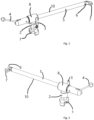
- Figures 1 and 2 show a penetrating nozzle (10) according to one embodiment. Only elements essential for understanding the invention are shown in the Figures. It should be noted that, for example, the quantity of various elements may vary and differ from those shown in a Figure.
- a penetrating nozzle similar to the examples in Figures 1 and 2 , or one with similar functionality, can be implemented as a separate apparatus or can at least partially or fully be a part of a fire-fighting system.
- An extinguishing system may also comprise several penetrating nozzles (10) according to different applications.
- the penetrating nozzle comprises coupler (1) for extinguishing agent, flow adjusting device (2) needed for the adjustment of flow including its activating device (3), pipe section (5) containing the flow path for the extinguishing agent, control device (6), which may for example be a joint, and nozzle head (7) performing the actual application of the extinguishing agent.
- Flow adjusting device (2) can preferably be for example a ball valve, but other types of valves and control devices can also be used.
- Activating device (3) associated with the flow adjusting device, can be used to adjust the flow of the extinguishing agent going through the adjusting device.
- Activating device (3) can be, for example, a manually operated lever or an electric motor.
- the penetrating nozzle of Figure 1 has been revised to extinguish fire in an enclosed space, but can be preferably revised for other extinguishing purposes, for example by changing the length and/or diameter of pipe section (5).
- a hole must first be made in the wall of the closed space through which nozzle head (7) of the penetrating nozzle can be pushed to the closed space.
- the diameter of pipe section (5), control device (6) and nozzle head (7) is no larger than 30 mm, 35 mm, 40 mm or 50 mm.
- nozzle head (7), control device (6) and at least part of pipe section (5) have been adapted to fit through a hole of circular cross section with a maximum diameter of 30 mm, 35 mm, 40 mm or 50 mm.
- the diameter of nozzle head (7) is at most equal to the diameter of pipe section (5).
- nozzle head (7) and control device (6) have a diameter no larger than the diameter of pipe section (5).
- nozzle head (7) and control device (6) are rotatable to a position where the nozzle head and the control device are parallel to the longitudinal axis of the pipe section, and both the nozzle head and the control device each have a diameter no larger than the diameter of the pipe section.
- the length of the pipe section is preferably at least 500 mm, 700 mm or 1000 mm.
- the pipe section must be large enough to allow a sufficient flow of extinguishing agent through it.
- the pipe section must be thin enough to allow a hole to be made in the wall of the closed space within a reasonable time through which nozzle head (7) can be pushed into the closed space.
- the diameter of the nozzle head and the control device, as well as the pipe section is in the range of 30 - 50 mm.
- the pipe section is preferably circular in cross-section, or substantially circular. Substantially circular in this context means a circular cross section, which may have small deviations for functional reasons.
- pipe section (5) has a circular cross-section for at least 50% of the length.
- pipe section (5) is circular in cross-section for at least 50% of its length, and the deviations from circular shape between the middle of the pipe section and the end of the pipe section towards control device (6) are towards the longitudinal axis of the pipe section.
- the cross section of the pipe section in this context means the outermost surface of the cross section, perpendicular to the longitudinal axis of the pipe section.
- the diameters of the control device and the nozzle head should preferably be no larger than the diameter of the pipe section.
- Control device (6) is controlled by activating device (4), which can be a lever, for example. Activating device can also be, for example, an electric motor and it can be controlled via a wireless remote connection, or it can operate independently.
- Control device (6) controls the position of nozzle head (7).
- the activating device and the control device are functionally linked and located at opposite ends of the pipe section.
- a wire rope, chain or other coupler of force runs between the control device and the activating device by which the movement of the activating device of the control device is communicated for the movement of the nozzle head.
- Said wire rope, chain or equivalent preferably runs inside the pipe section, in the same space as the fire extinguishing agent, thereby avoiding problems caused by heat.
- the movement of the activating device is communicated 1:1 for the movement of the nozzle head by means of a control device, whereby as the activating device is turned by a certain angle, the nozzle head turns the same angle.
- nozzle head (7) and activating device (4) of control device (6) have been arranged to be parallel in all positions. The nozzle head is then parallel to the pipe section whenever the activating device is also parallel to the pipe section. Similarly, when the end of activating device is turned upwards from this position for example by 60°, the end of nozzle head turns downwards by 60°, whereby the activating device and the nozzle head stay parallel. It is then easy to manage the flow of extinguishing agent coming from the nozzle head to the desired direction even if there was no line of sight into the closed space. An additional benefit is the simplicity of the solution, which makes it reliable and easy to manufacture.
- the extinguishing agent fed under pressure into coupler (1) of extinguishing agent, passes through flow adjusting device (2) into body (8).
- Pipe section (5) passes through the body and one or more openings are provided in the part moving in the body, whereby the extinguishing agent is able to flow into the pipe section and to the object to be extinguished, through nozzle head (7).
- the joint between body (8) and pipe section (5) is preferably sealed at the ends of the body.
- Pipe section (5) has been arranged to be turned inside body (8), whereby the spray can be freely directed in any direction, for example by turning the activating device (4) of control unit (6).
- Nozzle head (7) is removable, for example using threads, and can be replaced. By changing the size, quantity and orientation of the holes in the nozzle head, the angle and droplet size of the spray can be changed.
- the nozzle head is preferably arranged in such a way that the extinguishing agent spreads over a small area as it sprays, making it possible to direct the extinguishing agent precisely, for example to a desired point of the ceiling, or to a corner between the ceiling and the wall. A spray that is too fine or widely dispersed will have a short range and not enough extinguishing agent is applied to the required spot.
- penetrating nozzle One situation for the presented use of penetrating nozzle is to extinguish a fire in the loft of a single-family house. If it is safe to stay inside the house, a hole is drilled in the ceiling from which the nozzle head of the penetrating nozzle and part of the pipe are pushed through into the loft of the house. By turning the activating device of the control device, the nozzle head is turned approximately 80° - 90° in relation to the pipe section and the extinguishing agent is directed to the loft. Extinguishing agent can be efficiently directed all over the loft by rotating the pipe section around its axis, whereby the nozzle head turns together with the pipe section.
- the penetrating nozzle shown has been found to be particularly useful in situations where a hole must be made in the structure for a penetrating nozzle in order to extinguish a fire.
- the control device and part of the pipe section - have been arranged to be pushed through a round hole and are of moderate diameter, for example no more than 30 mm, 35 mm, 40 mm or 50 mm.
- a hole can be quickly bored with battery-powered tools and the penetrating nozzle that is pushed through the hole blocks the hole completely or almost completely. Consequently the fire does not get more air (oxygen) through the prepared hole and the extinguishing person is not exposed to flue gases.
- the size of the hole to be made matches the diameter of the penetrating nozzle for shape and size, as the fumes escaping from the hole will otherwise make extinguishing more difficult.
- the hole sealed with the penetrating nozzle also prevents the dangerous and unexpected discharge of a blowpipe flame from the hole, which is dangerous for the extinguishing person.
- the penetrating nozzle, as well as the nozzle head and control unit, have preferably been made of a heat-resistant material, such as steel, stainless steel, aluminum or composite material.
- the entire penetrating nozzle has been manufactured to withstand the pressure of the source of the extinguishing agent connected to the coupler of extinguishing agent, typically between 500 kPa and 2 MPa. Benefits of a penetrating nozzle when only pressurized extinguishing agent is used are properly demonstrated, as the apparatus does not have its own pump but merely directs the extinguishing agent flowing through the device to the desired target by means of the position of the nozzle head and the design of its holes.
- the penetrating nozzle comprises coupler (1) for extinguishing agent, adapted to be connected to a source of extinguishing agent, pipe section (5), from which a flow channel leads to coupler (1) for extinguishing agent, and pipe section (5) of nozzle head (7) at one end, where from said nozzle head a flow channel leads to pipe section (5).
- a penetrating nozzle is characterized in that it further comprises control device (6) functionally connected to nozzle head (7), wherein said control device (6) is located at the opposite end of said pipe section (5) with respect to nozzle head (7), said control device (6) being adapted to turn nozzle head (7) by deflecting the position of nozzle head (7) with respect to the longitudinal axis of pipe section (5).
- a penetrating nozzle further includes body (8), connected to coupler (1) for extinguishing agent and to pipe section (5), the body (8) of which forms a flow channel between said coupler (1) for extinguishing agent and said pipe section (5).
- pipe section (5) of penetrating nozzle has been rotatably connected to body (8) in such a way, that while attached to body (8), pipe section (5) can be rotated around the longitudinal axis of the pipe section in an unlimited manner while continuously maintaining a flow channel between pipe section (5) and coupler (1) for extinguishing agent.
- pipe section (5) of penetrating nozzle has been arranged to pass through body (8) and where one or more openings are arranged in the portion of pipe section (5) inside body (8) to form a flow channel between the pipe section and coupler (1) for extinguishing agent.
- control device (6) of the penetrating nozzle comprises manually operated activating device (4), which is functionally connected to nozzle head (7) in such a way that a change in the position of said activating device (4) will change the position of nozzle head (7).
- a functional connection between activating device (4) and nozzle head (7) has been formed by means of one or more wire ropes or chains.
- other known transmission devices such as a rigid or flexible drive shaft or gears, can also be used instead of, or in addition to wire ropes or chains.
- said one or more wire ropes or chains have been adapted to communicate the change in position of activating device (4) in order to change the position of nozzle head (7) with a ratio of 1:1.
- the diameter of said nozzle head (7) and pipe section (5) in a direction perpendicular to the longitudinal axis is no more than 50 mm, preferably no more than 30 mm, with the nozzle head in a position parallel to the pipe section.
- the penetrating nozzle comprises flow adjusting device (2) and an associated activating device (3), adapted to adjust the flow of the extinguishing agent in the penetrating nozzle.
Landscapes
- Health & Medical Sciences (AREA)
- Public Health (AREA)
- Business, Economics & Management (AREA)
- Emergency Management (AREA)
- Nozzles (AREA)
- Fire-Extinguishing By Fire Departments, And Fire-Extinguishing Equipment And Control Thereof (AREA)
Abstract
Description
- The invention relates to extinguishing and cooling of flue gases in an apartment fire, more commonly a fire in a closed space or in another burning object.
- Fires in a closed space have traditionally been extinguished by employing an aggressive technique of smoke diving inside the space. This is a risky and physically very stressful way to extinguish a fire and requires the fire fighters to have a high level of physical fitness. Occasionally a significant number of the rescue personnel arriving at the scene of a fire do not meet the criteria for smoke diving ability, and therefore extinguishing to be done from the inside cannot be undertaken and other alternatives must be used. Smoke diving also exposes the participating personnel to carcinogens.
- Most apartment fires or those more generally in closed spaces are what is called oxygen-limited fires, i.e. the intensity of combustion is limited by the oxygen necessary for combustion, more generally by the supply of air. This is a big advantage in extinguishing, as combustion is more restrained. In a traditional method, the door of the room needs to be opened upon entry, whereby the fire receives plenty of air and burning is accelerated. When extinguishing using a penetrating nozzle, only a small opening is needed, whereby the fire will not get more air due to extinguishing process.
- The need for, and associated exposure to smoke diving can be reduced by a practice of extinguishing the fire from outside a building or a burning compartment, using a penetrating nozzle. A penetrating nozzle can be introduced to a burning space without a need for personnel to enter the space.
- Penetrating nozzles have been used throughout the ages, among other things, for extinguishing and limiting a fire under a roof. Larger and longer pipes have been used among other things for extinguishing wood chip stacks and peat windrows. Smaller pipes have also been used for extinguishing apartment fires, where for example a hole is bored for the pipe in the window frame. The drawback of this model is that the spraying water only wets a fairly small proportion of the room's surfaces. The now presented penetrating nozzle is essentially different from the ones mentioned above in that a rotating component is placed at the end of the pipe, whereby the water can be directed to the desired part of the room. In this way the surfaces of the entire room can be wetted and extinguished by turning the tip and rotating the pipe.
- The penetrating nozzle according to an embodiment of the invention is based on the fact that at the end of an arm rotating around its axis, a turning nozzle head is constructed which produces a spray of water suitable for extinguishing a fire in an enclosed space, and the direction of the spray can be controlled. By means of directing the spray of extinguishing agent in the room space, it can be applied in the upper part of the room, effectively cooling the fire gases, so that the extinguishing agent also evaporates effectively. The spray of extinguishing agent can also be directed by rotating the pipe section, and the penetrating nozzle can be guided into the burning space through a small opening as well. The required opening is so small that it can be effectively bored, for example in a window frame or through a wall using conventional, preferably battery-operated tools.
- The invention will now be described in more detail in the form of preferred embodiments, with reference to the accompanying drawings, of which:
-
Figure 1 shows a penetrating nozzle according to one embodiment; and -
Figure 2 shows details of a penetrating nozzle according to one embodiment - The apparatus according to embodiments of the invention can be commonly used, for example, with various types of fire-fighting equipment, such as pumps and hoses. The use of the apparatus is not limited to be associated with any particular type of extinguishing system or structure, nor, for example to any particular type of extinguishing agent. Types of extinguishing agents used in connection with the apparatus can be for example liquid extinguishing agents such as water, as well as powdered and/or foam type extinguishing agents.
Figures 1 and 2 show a penetrating nozzle (10) according to one embodiment. Only elements essential for understanding the invention are shown in the Figures. It should be noted that, for example, the quantity of various elements may vary and differ from those shown in a Figure. A penetrating nozzle similar to the examples inFigures 1 and 2 , or one with similar functionality, can be implemented as a separate apparatus or can at least partially or fully be a part of a fire-fighting system. An extinguishing system may also comprise several penetrating nozzles (10) according to different applications. - In the example of
Figure 1 , the penetrating nozzle comprises coupler (1) for extinguishing agent, flow adjusting device (2) needed for the adjustment of flow including its activating device (3), pipe section (5) containing the flow path for the extinguishing agent, control device (6), which may for example be a joint, and nozzle head (7) performing the actual application of the extinguishing agent. - Flow adjusting device (2) can preferably be for example a ball valve, but other types of valves and control devices can also be used. Activating device (3), associated with the flow adjusting device, can be used to adjust the flow of the extinguishing agent going through the adjusting device. Activating device (3) can be, for example, a manually operated lever or an electric motor.
- The penetrating nozzle of
Figure 1 has been revised to extinguish fire in an enclosed space, but can be preferably revised for other extinguishing purposes, for example by changing the length and/or diameter of pipe section (5). When using the apparatus for extinguishing fire in a closed space, a hole must first be made in the wall of the closed space through which nozzle head (7) of the penetrating nozzle can be pushed to the closed space. Preferably, the diameter of pipe section (5), control device (6) and nozzle head (7) is no larger than 30 mm, 35 mm, 40 mm or 50 mm. Preferably, nozzle head (7), control device (6) and at least part of pipe section (5) have been adapted to fit through a hole of circular cross section with a maximum diameter of 30 mm, 35 mm, 40 mm or 50 mm. Preferably, the diameter of nozzle head (7) is at most equal to the diameter of pipe section (5). Preferably, nozzle head (7) and control device (6) have a diameter no larger than the diameter of pipe section (5). In one embodiment, nozzle head (7) and control device (6) are rotatable to a position where the nozzle head and the control device are parallel to the longitudinal axis of the pipe section, and both the nozzle head and the control device each have a diameter no larger than the diameter of the pipe section. - The length of the pipe section is preferably at least 500 mm, 700 mm or 1000 mm. The pipe section must be large enough to allow a sufficient flow of extinguishing agent through it. On the other hand, the pipe section must be thin enough to allow a hole to be made in the wall of the closed space within a reasonable time through which nozzle head (7) can be pushed into the closed space. Preferably, the diameter of the nozzle head and the control device, as well as the pipe section, is in the range of 30 - 50 mm. The pipe section is preferably circular in cross-section, or substantially circular. Substantially circular in this context means a circular cross section, which may have small deviations for functional reasons. In one embodiment, pipe section (5) has a circular cross-section for at least 50% of the length. In one embodiment, pipe section (5) is circular in cross-section for at least 50% of its length, and the deviations from circular shape between the middle of the pipe section and the end of the pipe section towards control device (6) are towards the longitudinal axis of the pipe section. The cross section of the pipe section in this context means the outermost surface of the cross section, perpendicular to the longitudinal axis of the pipe section. The diameters of the control device and the nozzle head should preferably be no larger than the diameter of the pipe section.
- Control device (6) is controlled by activating device (4), which can be a lever, for example. Activating device can also be, for example, an electric motor and it can be controlled via a wireless remote connection, or it can operate independently. Control device (6) controls the position of nozzle head (7). The activating device and the control device are functionally linked and located at opposite ends of the pipe section. Preferably a wire rope, chain or other coupler of force runs between the control device and the activating device by which the movement of the activating device of the control device is communicated for the movement of the nozzle head. Said wire rope, chain or equivalent preferably runs inside the pipe section, in the same space as the fire extinguishing agent, thereby avoiding problems caused by heat. Preferably, the movement of the activating device is communicated 1:1 for the movement of the nozzle head by means of a control device, whereby as the activating device is turned by a certain angle, the nozzle head turns the same angle. In one preferred embodiment, nozzle head (7) and activating device (4) of control device (6) have been arranged to be parallel in all positions. The nozzle head is then parallel to the pipe section whenever the activating device is also parallel to the pipe section. Similarly, when the end of activating device is turned upwards from this position for example by 60°, the end of nozzle head turns downwards by 60°, whereby the activating device and the nozzle head stay parallel. It is then easy to manage the flow of extinguishing agent coming from the nozzle head to the desired direction even if there was no line of sight into the closed space. An additional benefit is the simplicity of the solution, which makes it reliable and easy to manufacture.
- The extinguishing agent, fed under pressure into coupler (1) of extinguishing agent, passes through flow adjusting device (2) into body (8). Pipe section (5) passes through the body and one or more openings are provided in the part moving in the body, whereby the extinguishing agent is able to flow into the pipe section and to the object to be extinguished, through nozzle head (7). The joint between body (8) and pipe section (5) is preferably sealed at the ends of the body. Pipe section (5) has been arranged to be turned inside body (8), whereby the spray can be freely directed in any direction, for example by turning the activating device (4) of control unit (6).
- In the example of
Figure 2 , the pipe is shown from the other side, where the structure of control device (6) is more clearly visible. Nozzle head (7) is removable, for example using threads, and can be replaced. By changing the size, quantity and orientation of the holes in the nozzle head, the angle and droplet size of the spray can be changed. The nozzle head is preferably arranged in such a way that the extinguishing agent spreads over a small area as it sprays, making it possible to direct the extinguishing agent precisely, for example to a desired point of the ceiling, or to a corner between the ceiling and the wall. A spray that is too fine or widely dispersed will have a short range and not enough extinguishing agent is applied to the required spot. - One situation for the presented use of penetrating nozzle is to extinguish a fire in the loft of a single-family house. If it is safe to stay inside the house, a hole is drilled in the ceiling from which the nozzle head of the penetrating nozzle and part of the pipe are pushed through into the loft of the house. By turning the activating device of the control device, the nozzle head is turned approximately 80° - 90° in relation to the pipe section and the extinguishing agent is directed to the loft. Extinguishing agent can be efficiently directed all over the loft by rotating the pipe section around its axis, whereby the nozzle head turns together with the pipe section.
- The penetrating nozzle shown has been found to be particularly useful in situations where a hole must be made in the structure for a penetrating nozzle in order to extinguish a fire. End of the penetrating nozzle to be pushed through a hole - the nozzle head, the control device and part of the pipe section - have been arranged to be pushed through a round hole and are of moderate diameter, for example no more than 30 mm, 35 mm, 40 mm or 50 mm. Hence a hole can be quickly bored with battery-powered tools and the penetrating nozzle that is pushed through the hole blocks the hole completely or almost completely. Consequently the fire does not get more air (oxygen) through the prepared hole and the extinguishing person is not exposed to flue gases. Especially when working from the roof, it is important that the size of the hole to be made matches the diameter of the penetrating nozzle for shape and size, as the fumes escaping from the hole will otherwise make extinguishing more difficult. The hole sealed with the penetrating nozzle also prevents the dangerous and unexpected discharge of a blowpipe flame from the hole, which is dangerous for the extinguishing person.
- The penetrating nozzle, as well as the nozzle head and control unit, have preferably been made of a heat-resistant material, such as steel, stainless steel, aluminum or composite material. The entire penetrating nozzle has been manufactured to withstand the pressure of the source of the extinguishing agent connected to the coupler of extinguishing agent, typically between 500 kPa and 2 MPa. Benefits of a penetrating nozzle when only pressurized extinguishing agent is used are properly demonstrated, as the apparatus does not have its own pump but merely directs the extinguishing agent flowing through the device to the desired target by means of the position of the nozzle head and the design of its holes.
- One embodiment of the invention is penetrating nozzle (10) for extinguishing a burning object. The penetrating nozzle according to the embodiment comprises coupler (1) for extinguishing agent, adapted to be connected to a source of extinguishing agent, pipe section (5), from which a flow channel leads to coupler (1) for extinguishing agent, and pipe section (5) of nozzle head (7) at one end, where from said nozzle head a flow channel leads to pipe section (5). A penetrating nozzle according to the embodiment is characterized in that it further comprises control device (6) functionally connected to nozzle head (7), wherein said control device (6) is located at the opposite end of said pipe section (5) with respect to nozzle head (7), said control device (6) being adapted to turn nozzle head (7) by deflecting the position of nozzle head (7) with respect to the longitudinal axis of pipe section (5).
- In one embodiment a penetrating nozzle further includes body (8), connected to coupler (1) for extinguishing agent and to pipe section (5), the body (8) of which forms a flow channel between said coupler (1) for extinguishing agent and said pipe section (5).
- In one embodiment, pipe section (5) of penetrating nozzle has been rotatably connected to body (8) in such a way, that while attached to body (8), pipe section (5) can be rotated around the longitudinal axis of the pipe section in an unlimited manner while continuously maintaining a flow channel between pipe section (5) and coupler (1) for extinguishing agent.
- In one embodiment pipe section (5) of penetrating nozzle has been arranged to pass through body (8) and where one or more openings are arranged in the portion of pipe section (5) inside body (8) to form a flow channel between the pipe section and coupler (1) for extinguishing agent.
- In one embodiment, control device (6) of the penetrating nozzle comprises manually operated activating device (4), which is functionally connected to nozzle head (7) in such a way that a change in the position of said activating device (4) will change the position of nozzle head (7).
- In one embodiment, a functional connection between activating device (4) and nozzle head (7) has been formed by means of one or more wire ropes or chains. Alternatively, other known transmission devices, such as a rigid or flexible drive shaft or gears, can also be used instead of, or in addition to wire ropes or chains. Preferably said one or more wire ropes or chains have been adapted to communicate the change in position of activating device (4) in order to change the position of nozzle head (7) with a ratio of 1:1.
- In one embodiment, the diameter of said nozzle head (7) and pipe section (5) in a direction perpendicular to the longitudinal axis, is no more than 50 mm, preferably no more than 30 mm, with the nozzle head in a position parallel to the pipe section.
- In one embodiment, the penetrating nozzle comprises flow adjusting device (2) and an associated activating device (3), adapted to adjust the flow of the extinguishing agent in the penetrating nozzle.
- It is obvious to those skilled in the art that, as technology evolves, the basic idea of the invention can be implemented in many different ways. The invention and its applications are therefore not limited to the examples described above, and may vary within the scope of the patent claims.
Claims (10)
- A penetrating nozzle (10) for extinguishing a burning object, comprising:coupler (1) for extinguishing agent, adapted to be connected to a source of extinguishing agent,pipe section (5), from which a flow channel leads to coupler (1) for extinguishing agent,nozzle head (7) at one end of pipe section (5) from which there is a flow channel from said nozzle head to pipe section (5), andcontrol device (6), which is functionally connected to nozzle head (7), and said control device (6) being at the opposite end of said pipe section (5) with respect to nozzle head (7), whereby control device (6) is adapted to turn nozzle head (7) by deflecting the position of nozzle head (7) with respect to the longitudinal axis of pipe section (5), where control device (6) comprises a manually operated activating device (4), which is functionally connected by means of a transmission device to nozzle head (7) in such a way that a change in the position of said activating device (4) will cause a change in the position of nozzle head (7),said penetrating nozzle being characterized in that said transmission device runs inside pipe section (5) in the same space as the extinguishing agent.
- A penetrating nozzle according to claim 1, further comprising body (8), connected to coupler (1) for extinguishing agent and to pipe section (5), the body (8) of which forms a flow channel between said coupler (1) for extinguishing agent and said pipe section (5).
- A penetrating nozzle according to claim 2, where pipe section (5) has been rotatably connected to body (8) in such a way, that while attached to body (8), pipe section (5) can be rotated around the longitudinal axis of the pipe section in an unlimited manner while continuously maintaining a flow channel between pipe section (5) and coupler (1) for extinguishing agent.
- A penetrating nozzle according to claim 2 or 3, where pipe section (5) has been arranged to pass through body (8) and where one or more openings are arranged in the portion of pipe section (5) inside body (8) to form a flow channel between the pipe section and coupler (1) for extinguishing agent.
- A penetrating nozzle according to claim 1, where said one or more wire ropes or chains have been adapted to communicate the change in position of activating device (4) in order to change the position of nozzle head (7) with a ratio of 1:1.
- A penetrating nozzle according to one of claims 1 to 5, wherein the diameter of said nozzle head (7) and pipe portion (5) in a direction perpendicular to the longitudinal axis is no larger than 50 mm when the nozzle head is in a position parallel to the pipe section.
- A penetrating nozzle according to claim 6, wherein the diameter of said nozzle head (7) and pipe portion (5) in a direction perpendicular to the longitudinal axis is no larger than 30 mm when the nozzle head is in a position parallel to the pipe section.
- A penetrating nozzle according to one of claims 1 - 7, comprising flow adjusting device (2) and an associated activating device (3), adapted to adjust the flow of the extinguishing agent in the penetrating nozzle.
- A penetrating nozzle according to one of claims 1 to 8, wherein said transmission means comprises one or more wire ropes or chains.
- A penetrating nozzle of one of claims 1 to 8, wherein said transmission device comprises one or more wire ropes, chains, drive shafts or sprockets.
Applications Claiming Priority (1)
| Application Number | Priority Date | Filing Date | Title |
|---|---|---|---|
| FI20225182A FI130704B1 (en) | 2022-02-28 | 2022-02-28 | DIRECTABLE SPRAY PIPE FOR EXTINGUISHING FIRES |
Publications (3)
| Publication Number | Publication Date |
|---|---|
| EP4234046A1 true EP4234046A1 (en) | 2023-08-30 |
| EP4234046C0 EP4234046C0 (en) | 2025-12-10 |
| EP4234046B1 EP4234046B1 (en) | 2025-12-10 |
Family
ID=85505613
Family Applications (1)
| Application Number | Title | Priority Date | Filing Date |
|---|---|---|---|
| EP23158960.7A Active EP4234046B1 (en) | 2022-02-28 | 2023-02-28 | Directable penetrating nozzle for extinguishing fires |
Country Status (2)
| Country | Link |
|---|---|
| EP (1) | EP4234046B1 (en) |
| FI (1) | FI130704B1 (en) |
Citations (3)
| Publication number | Priority date | Publication date | Assignee | Title |
|---|---|---|---|---|
| JPS6334450U (en) * | 1986-08-26 | 1988-03-05 | ||
| CN103372273A (en) * | 2012-04-25 | 2013-10-30 | 王贵国 | Hand-held-type omnibearing firefighting water gun |
| KR101713236B1 (en) * | 2016-12-09 | 2017-03-09 | 주식회사 한국나이스기술단 | Firefighting injection apparatus and system |
-
2022
- 2022-02-28 FI FI20225182A patent/FI130704B1/en active
-
2023
- 2023-02-28 EP EP23158960.7A patent/EP4234046B1/en active Active
Patent Citations (3)
| Publication number | Priority date | Publication date | Assignee | Title |
|---|---|---|---|---|
| JPS6334450U (en) * | 1986-08-26 | 1988-03-05 | ||
| CN103372273A (en) * | 2012-04-25 | 2013-10-30 | 王贵国 | Hand-held-type omnibearing firefighting water gun |
| KR101713236B1 (en) * | 2016-12-09 | 2017-03-09 | 주식회사 한국나이스기술단 | Firefighting injection apparatus and system |
Also Published As
| Publication number | Publication date |
|---|---|
| FI130704B1 (en) | 2024-01-29 |
| FI20225182A1 (en) | 2023-08-29 |
| EP4234046C0 (en) | 2025-12-10 |
| EP4234046B1 (en) | 2025-12-10 |
Similar Documents
| Publication | Publication Date | Title |
|---|---|---|
| CA1303562C (en) | Foam generator adjustable to produce foam having various expansion ratios | |
| US5433383A (en) | Whirler nozzle for fire fighting equipment | |
| US4485877A (en) | Wall penetrating fire extinguishing device | |
| JP2916195B2 (en) | Spray nozzle for fire extinguishing, fire extinguishing system and fire extinguishing method | |
| US2813753A (en) | Fog nozzle | |
| US20160069578A1 (en) | Smoke elimination device | |
| EP4234046B1 (en) | Directable penetrating nozzle for extinguishing fires | |
| US20170100616A1 (en) | Firefighting Nozzle | |
| JP5456207B2 (en) | Dual mode active agent release system with multiple active agent release capabilities | |
| US2484942A (en) | Nozzle construction | |
| KR101711046B1 (en) | Fire extinguishing apparatus for smoke removing | |
| CN215741537U (en) | Fire extinguishing device for outer surface of building | |
| US12582857B2 (en) | Device for generating a jet of two-phase fluid | |
| CN210583436U (en) | Multi-angle water-outlet fire-fighting lance | |
| US3463234A (en) | Method and apparatus for fire control | |
| RU189618U1 (en) | Fireman Portable Barrel | |
| JP3727880B2 (en) | Two-fluid spraying device | |
| RU196191U1 (en) | Portable fire barrel | |
| RU189679U1 (en) | Firefighter hand barrel | |
| CN223818087U (en) | A water gun for extinguishing vertical spread of water on the facade of multi-story buildings | |
| CN111450430A (en) | Interlayer fire-extinguishing multifunctional water gun | |
| JPH119715A (en) | Telescopic boom type fire engine | |
| CN223569915U (en) | Fire-fighting safety evacuation channel | |
| JPH0199578A (en) | Nozzle device and quenching tool | |
| CN222623589U (en) | Multifunctional water mist negative pressure smoke-discharging fire-extinguishing device |
Legal Events
| Date | Code | Title | Description |
|---|---|---|---|
| PUAI | Public reference made under article 153(3) epc to a published international application that has entered the european phase |
Free format text: ORIGINAL CODE: 0009012 |
|
| STAA | Information on the status of an ep patent application or granted ep patent |
Free format text: STATUS: REQUEST FOR EXAMINATION WAS MADE |
|
| 17P | Request for examination filed |
Effective date: 20230228 |
|
| AK | Designated contracting states |
Kind code of ref document: A1 Designated state(s): AL AT BE BG CH CY CZ DE DK EE ES FI FR GB GR HR HU IE IS IT LI LT LU LV MC ME MK MT NL NO PL PT RO RS SE SI SK SM TR |
|
| GRAP | Despatch of communication of intention to grant a patent |
Free format text: ORIGINAL CODE: EPIDOSNIGR1 |
|
| STAA | Information on the status of an ep patent application or granted ep patent |
Free format text: STATUS: GRANT OF PATENT IS INTENDED |
|
| INTG | Intention to grant announced |
Effective date: 20250707 |
|
| GRAS | Grant fee paid |
Free format text: ORIGINAL CODE: EPIDOSNIGR3 |
|
| GRAA | (expected) grant |
Free format text: ORIGINAL CODE: 0009210 |
|
| STAA | Information on the status of an ep patent application or granted ep patent |
Free format text: STATUS: THE PATENT HAS BEEN GRANTED |
|
| AK | Designated contracting states |
Kind code of ref document: B1 Designated state(s): AL AT BE BG CH CY CZ DE DK EE ES FI FR GB GR HR HU IE IS IT LI LT LU LV MC ME MK MT NL NO PL PT RO RS SE SI SK SM TR |
|
| REG | Reference to a national code |
Ref country code: CH Ref legal event code: F10 Free format text: ST27 STATUS EVENT CODE: U-0-0-F10-F00 (AS PROVIDED BY THE NATIONAL OFFICE) Effective date: 20251210 Ref country code: GB Ref legal event code: FG4D |
|
| REG | Reference to a national code |
Ref country code: DE Ref legal event code: R096 Ref document number: 602023009413 Country of ref document: DE |
|
| REG | Reference to a national code |
Ref country code: IE Ref legal event code: FG4D |
|
| U01 | Request for unitary effect filed |
Effective date: 20260103 |
|
| U07 | Unitary effect registered |
Designated state(s): AT BE BG DE DK EE FI FR IT LT LU LV MT NL PT RO SE SI Effective date: 20260113 |
|
| PG25 | Lapsed in a contracting state [announced via postgrant information from national office to epo] |
Ref country code: ES Free format text: LAPSE BECAUSE OF FAILURE TO SUBMIT A TRANSLATION OF THE DESCRIPTION OR TO PAY THE FEE WITHIN THE PRESCRIBED TIME-LIMIT Effective date: 20251210 |
|
| PG25 | Lapsed in a contracting state [announced via postgrant information from national office to epo] |
Ref country code: NO Free format text: LAPSE BECAUSE OF FAILURE TO SUBMIT A TRANSLATION OF THE DESCRIPTION OR TO PAY THE FEE WITHIN THE PRESCRIBED TIME-LIMIT Effective date: 20260310 |
|
| PG25 | Lapsed in a contracting state [announced via postgrant information from national office to epo] |
Ref country code: HR Free format text: LAPSE BECAUSE OF FAILURE TO SUBMIT A TRANSLATION OF THE DESCRIPTION OR TO PAY THE FEE WITHIN THE PRESCRIBED TIME-LIMIT Effective date: 20251210 |
|
| U20 | Renewal fee for the european patent with unitary effect paid |
Year of fee payment: 4 Effective date: 20260309 |
|
| PG25 | Lapsed in a contracting state [announced via postgrant information from national office to epo] |
Ref country code: RS Free format text: LAPSE BECAUSE OF FAILURE TO SUBMIT A TRANSLATION OF THE DESCRIPTION OR TO PAY THE FEE WITHIN THE PRESCRIBED TIME-LIMIT Effective date: 20260310 |