EP4233620A2 - Sole structure for article of footwear - Google Patents
Sole structure for article of footwear Download PDFInfo
- Publication number
- EP4233620A2 EP4233620A2 EP23176134.7A EP23176134A EP4233620A2 EP 4233620 A2 EP4233620 A2 EP 4233620A2 EP 23176134 A EP23176134 A EP 23176134A EP 4233620 A2 EP4233620 A2 EP 4233620A2
- Authority
- EP
- European Patent Office
- Prior art keywords
- sole structure
- segment
- insert
- channel
- main body
- Prior art date
- Legal status (The legal status is an assumption and is not a legal conclusion. Google has not performed a legal analysis and makes no representation as to the accuracy of the status listed.)
- Granted
Links
Images














Classifications
-
- A—HUMAN NECESSITIES
- A43—FOOTWEAR
- A43B—CHARACTERISTIC FEATURES OF FOOTWEAR; PARTS OF FOOTWEAR
- A43B13/00—Soles; Sole-and-heel integral units
- A43B13/14—Soles; Sole-and-heel integral units characterised by the constructive form
- A43B13/16—Pieced soles
-
- A—HUMAN NECESSITIES
- A43—FOOTWEAR
- A43B—CHARACTERISTIC FEATURES OF FOOTWEAR; PARTS OF FOOTWEAR
- A43B13/00—Soles; Sole-and-heel integral units
- A43B13/02—Soles; Sole-and-heel integral units characterised by the material
-
- A—HUMAN NECESSITIES
- A43—FOOTWEAR
- A43B—CHARACTERISTIC FEATURES OF FOOTWEAR; PARTS OF FOOTWEAR
- A43B13/00—Soles; Sole-and-heel integral units
- A43B13/02—Soles; Sole-and-heel integral units characterised by the material
- A43B13/04—Plastics, rubber or vulcanised fibre
-
- A—HUMAN NECESSITIES
- A43—FOOTWEAR
- A43B—CHARACTERISTIC FEATURES OF FOOTWEAR; PARTS OF FOOTWEAR
- A43B13/00—Soles; Sole-and-heel integral units
- A43B13/14—Soles; Sole-and-heel integral units characterised by the constructive form
- A43B13/143—Soles; Sole-and-heel integral units characterised by the constructive form provided with wedged, concave or convex end portions, e.g. for improving roll-off of the foot
- A43B13/145—Convex portions, e.g. with a bump or projection, e.g. 'Masai' type shoes
-
- A—HUMAN NECESSITIES
- A43—FOOTWEAR
- A43B—CHARACTERISTIC FEATURES OF FOOTWEAR; PARTS OF FOOTWEAR
- A43B13/00—Soles; Sole-and-heel integral units
- A43B13/14—Soles; Sole-and-heel integral units characterised by the constructive form
- A43B13/22—Soles made slip-preventing or wear-resisting, e.g. by impregnation or spreading a wear-resisting layer
-
- A—HUMAN NECESSITIES
- A43—FOOTWEAR
- A43B—CHARACTERISTIC FEATURES OF FOOTWEAR; PARTS OF FOOTWEAR
- A43B13/00—Soles; Sole-and-heel integral units
- A43B13/14—Soles; Sole-and-heel integral units characterised by the constructive form
- A43B13/22—Soles made slip-preventing or wear-resisting, e.g. by impregnation or spreading a wear-resisting layer
- A43B13/223—Profiled soles
-
- A—HUMAN NECESSITIES
- A43—FOOTWEAR
- A43B—CHARACTERISTIC FEATURES OF FOOTWEAR; PARTS OF FOOTWEAR
- A43B3/00—Footwear characterised by the shape or the use
- A43B3/0036—Footwear characterised by the shape or the use characterised by a special shape or design
- A43B3/0068—V-shaped
-
- A—HUMAN NECESSITIES
- A43—FOOTWEAR
- A43B—CHARACTERISTIC FEATURES OF FOOTWEAR; PARTS OF FOOTWEAR
- A43B5/00—Footwear for sporting purposes
Definitions
- the present disclosure relates generally to sole structures for articles of footwear and more particularly to sole structures incorporating a composite ground-contacting surface.
- Articles of footwear conventionally include an upper and a sole structure.
- the upper may be formed from any suitable material(s) to receive, secure, and support a foot on the sole structure.
- the upper may cooperate with laces, straps, or other fasteners to adjust the fit of the upper around the foot.
- Sole structures generally include a layered arrangement extending between a ground surface and the upper.
- One layer of the sole structure includes an outsole that provides abrasionresistance and traction with the ground surface.
- the outsole may be formed using materials and geometries that impart durability and wear-resistance, as well as enhance traction with the ground surface.
- Another layer of the sole structure includes a midsole disposed between the outsole and the upper.
- the midsole provides cushioning for the foot and may be partially formed from a polymer foam material that compresses resiliently under an applied load to cushion the foot by attenuating ground-reaction forces.
- the midsole may additionally or alternatively incorporate a fluid-filled bladder to increase durability of the sole structure, as well as to provide cushioning to the foot by compressing resiliently under an applied load to attenuate ground-reaction forces.
- Sole structures may also include a comfort-enhancing insole or a sockliner located within a void proximate to the bottom portion of the upper and a strobel attached to the upper and disposed between the midsole and the insole or sockliner.
- Example configurations will now be described more fully with reference to the accompanying drawings.
- Example configurations are provided so that this disclosure will be thorough, and will fully convey the scope of the disclosure to those of ordinary skill in the art. Specific details are set forth such as examples of specific components, devices, and methods, to provide a thorough understanding of configurations of the present disclosure. It will be apparent to those of ordinary skill in the art that specific details need not be employed, that example configurations may be embodied in many different forms, and that the specific details and the example configurations should not be construed to limit the scope of the disclosure.
- first, second, third, etc. may be used herein to describe various elements, components, regions, layers and/or sections. These elements, components, regions, layers and/or sections should not be limited by these terms. These terms may be only used to distinguish one element, component, region, layer or section from another region, layer or section. Terms such as “first,” “second,” and other numerical terms do not imply a sequence or order unless clearly indicated by the context. Thus, a first element, component, region, layer or section discussed below could be termed a second element, component, region, layer or section without departing from the teachings of the example configurations.
- the sole structure includes a main body formed of a first material and defining a first portion of a ground-engaging surface.
- the main body includes a first channel defined by a first segment extending along a first axis and a second segment extending along a second axis transverse to the first axis.
- the sole structure also includes at least one insert formed of a second material and received by the main body.
- the at least one insert defines a second portion of the ground-engaging surface that is flush with the first region of the ground-engaging surface and has a second channel including a third segment extending along a third axis parallel to the first axis and a fourth segment extending along a fourth axis transverse to the third axis and substantially parallel to the second axis.
- One of the first channel and the second channel defines an interface between the main body and the insert.
- the at least one insert includes an anterior insert defining at least a portion of a forefoot region of the ground-engaging surface, and a posterior insert defining at least a portion of a heel region of the ground-engaging surface.
- the anterior insert may include the second channel and the posterior insert may include a third channel having a fifth segment extending along a fifth axis substantially parallel to the first axis and a sixth segment extending along a sixth axis transverse to the fifth axis and substantially parallel to the second axis, the third channel defining an interface between the main body and the posterior insert.
- the main body may define at least a portion of a midfoot region of the sole structure and may separate the anterior insert from the posterior insert.
- the main body is formed of a foam material and the at least one insert is formed of a rubber material.
- the main body may define at least one side surface of the sole structure, a portion of the first channel of the main body extending onto the side surface.
- the at least one side surface of the sole structure may include a lateral side surface having a first portion of the first channel formed therein and a medial side surface having a second portion of the second channel formed therein.
- the main body includes a socket defined by a recessed surface offset from the ground-engaging surface and a sidewall extending between the ground-engaging surface and the recessed surface and intersecting the at least one side surface to define a notch.
- the insert is received by the socket, a first portion of a peripheral surface of the insert mating with the sidewall of the socket and a second portion of the peripheral surface of the insert being disposed in the notch and flush with the at least one side surface.
- the first region of the ground-engaging surface is continuous and flush with the second region of the ground-engaging surface.
- the sole structure includes a main body defining a first region of a ground-engaging surface and at least one side surface extending from the ground-engaging surface.
- the sole structure also includes at least one insert received by the main body, which defines a second region of the ground-engaging surface.
- the sole structure further includes a first channel defined by a first plurality of segments including a first segment extending from a first node to a second node along a first axis, a second segment extending from a third node to a fourth node along a second axis transverse to the first axis, and a third segment extending from a fifth node to a sixth node along a third axis transverse to the second axis and substantially parallel to the first axis.
- Implementations of the disclosure may include one of more of the following optional features.
- the first segment is formed along a first side surface
- the second segment is formed in the first region of the ground-engaging surface
- the third segment is formed along a second side surface.
- the sole structure includes a second channel defined by a second plurality of segments including a fourth segment extending from a seventh node to an eighth node along a fourth axis substantially parallel to the first axis and a fifth segment extending from a ninth node to a tenth node along a fifth axis substantially parallel to the second axis.
- the first channel may be formed only in the main body of the sole structure and the second channel may be formed only in the insert of the sole structure.
- the insert may include an aperture through at least one of the nodes of the channel, such that the main body is exposed through the aperture.
- a first portion of the first channel may be formed in the main body and a second portion of the first channel is formed in the insert.
- At least one of the segments may include an intermediate node.
- widths of each of the first channel and the second channel may be variable in a direction along at least one of the axes.
- the second node and the third node define a first common node and the fourth node and the fifth node define a second common node, such that the first segment, the second segment, and the third segment are serially connected.
- the second node, the third node, and the fifth node may define a common node such that the second segment and the third segment define first and second sub-channels, respectively.
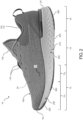
- an article of footwear 10 includes an upper 100 and sole structure 200.
- the article of footwear 10 may be divided into one or more regions.
- the regions may include a forefoot region 12, a mid-foot region 14, and a heel region 16.
- the forefoot region 12 may be subdivided into a toe portion 12 T corresponding with phalanges and a ball region 12 B associated with metatarsal bones of a foot.
- the mid-foot region 14 may correspond with an arch area of the foot, and the heel region 16 may correspond with rear portions of the foot, including a calcaneus bone.
- the footwear 10 may further include an anterior end 18 associated with a forwardmost point of the forefoot region 12, and a posterior end 20 corresponding to a rearward-most point of the heel region 16.
- a longitudinal axis A F of the footwear 10 extends along a length of the footwear 10 from the anterior end 18 to the posterior end 20, and generally divides the footwear 10 into a lateral region 22 and a medial region 24. Accordingly, the lateral region 22 and the medial region 24 respectively correspond with opposite sides of the footwear 10 and extend through the regions 12, 14, 16.
- the longitudinal axis A F of the footwear may be arcuate in shape, such that the longitudinal axis A F is substantially centrally located between the lateral side 22 and the medial side 24 along the length of the footwear 10.
- the upper 100 includes interior surfaces that define an interior void 102 configured to receive and secure a foot for support on sole structure 200.
- the upper 100 may be formed from one or more materials that are stitched or adhesively bonded together to form the interior void 102. Suitable materials of the upper may include, but are not limited to, mesh, textiles, foam, leather, and synthetic leather. The materials may be selected and located to impart properties of durability, air-permeability, wear-resistance, flexibility, and comfort.
- the upper 100 includes a strobel (not shown) having a bottom surface opposing the sole structure 200 and an opposing top surface defining a footbed 108 of the interior void 102. Stitching or adhesives may secure the strobel to the upper 100.
- the footbed 108 may be contoured to conform to a profile of the bottom surface (e.g., plantar) of the foot.
- the upper 100 may also incorporate additional layers such as an insole 110 or sockliner that may be disposed upon the strobel and reside within the interior void 102 of the upper 100 to receive a plantar surface of the foot to enhance the comfort of the article of footwear 10.
- An ankle opening 112 in the heel region 16 may provide access to the interior void 102.
- the ankle opening 112 may receive a foot to secure the foot within the void 102 and facilitate entry and removal of the foot from and to the interior void 102.
- one or more fasteners extend along the upper 100 to adjust a fit of the interior void 102 around the foot and to accommodate entry and removal of the foot therefrom.
- the upper 100 may include apertures 116 such as eyelets and/or other engagement features such as fabric or mesh loops that receive the fasteners.
- the fasteners may include laces, straps, cords, hook-and-loop, or any other suitable type of fastener.
- the upper 100 may include a tongue portion 118 that extends between the interior void 102 and the fasteners.
- FIGS. 7-24 several alternative implementations of a sole structure 200 according to the instant disclosure are provided.
- like reference numerals are used hereinafter and in the drawings to identify common components having the same design.
- Like reference numerals containing letter extensions are used to identify variations of common components within an implementation of the sole structure 200
- reference numerals containing prime symbols (') are used to identify examples of common components that have been modified between implementations
- reference numerals containing subscripts are used to identify sub-components of a parent component. Accordingly, reference to components using numerals not including letter extensions, prime symbols, or subscripts is understood to collectively refer to all variations of a common component including like reference numerals, including those examples having letter extensions, prime symbols, and/or subscripts.
- the sole structure 200, 200'-200′′′ includes a ground-engaging surface 202, 202'-202′′′ configured to interface with a ground surface when the article of footwear 10 is worn by a user.
- the sole structure 200 is further defined by an upper surface 204, which is formed on an opposite side of the sole structure 200 from the ground-engaging surface 202 and is configured to oppose the upper, thereby providing a foot-support surface.
- a side surface 206, 206'-206′′′ extends between the ground-engaging surface 202 and the upper surface 204, and defines an outer periphery of the sole structure 200.
- the illustrated sole structure 200 includes a substantially continuous, contoured side surface 206 extending around the entire periphery of the sole structure 200, it may be defined as comprising a lateral side surface 206a, 206a'-206a′′′ extending substantially along the lateral side 22 of the sole structure 200, a medial side surface 206b, 206b'-206b′′′ extending substantially along the medial side 24 of the sole structure 200, an anterior side surface 206c, 206'-206′′′ extending around the forefoot region 12 between the lateral side surface 206a and the medial side surface 206b, and a posterior side surface 206d, 206d'-206′′′ extending around the heel region 16 between the lateral side surface 206a and the medial side surface 206b.
- the anterior side surface 206c may be defined by a toe cap, or tab 208, which protrudes from the upper surface 204 and is configured to attach or bond to the upper 100 at the anterior end 18.
- a transition 209 may be formed at the intersection of the ground-engaging surface 202 and the side surface 206, and may be defined by a variable radius R T , R T1 , R T2 extending around the periphery of the sole structure 200.
- the transition 209 may be defined by a first radius R T1 providing a relatively pronounced transition 209 between the ground-engaging surface 202 and the side surface 206.
- the transition 209 between the ground-engaging surface 202 and the side surface 206 in the mid-foot region 14 may be defined by a relatively large radius R T2 , whereby the ground-engaging surface 202 and the side surface 206 are substantially continuously formed.
- the sole structure 200 further includes a plurality of channels 210, 210'-210′′′ formed therein.
- the channels 210 are defined by a recessed surface 212 offset from the ground-engaging surface 202 by a depth Dc, and an opposing pair of sidewalls 214 extending from the ground-engaging surface 202 to the recessed surface 212.
- a distance between the sidewalls 214 defines a width Wc of the channels 210, as shown in FIGS. 8C , 14C , and 20C .
- the depths Dc and the widths Wc of the channels 210 may be variable along lengths of the channels 210.
- Each of the channels 210 includes a plurality of elongate segments 222.
- Each of the segments 222 includes two or more nodes 224 connected to each other by intermediate necked regions 226, and extends from a first end node 224a to a second end node 224a along a longitudinal segment axis As, as shown in FIG. 8A .
- One or more of the segments 222 may further include intermediate nodes 224b disposed between the end nodes 224a along the segment axis As, and interconnected to each other by the necked regions 226. Accordingly, the end nodes 224a, the intermediate nodes 224b, and the necked regions 226 of a respective segment 222 are all aligned along a common segment axis As.
- the segment axes A S1-n of each of the segments 222 may be arranged at oblique angles with respect to the longitudinal axis A F of the footwear 10.
- the width Wc of each of the channels 210 is variable along a length of the channels 210. More specifically, the width Wc is variable along each segment 222, whereby a first width W C1 of the segment 222 at the nodes 224 is greater than a second width W C2 of the segment 222 at each of the necked regions 226, as shown in FIGS. 8B , 14B , and 20B .
- the sidewalls 214 may be described as having an undulated shape, whereby the sidewalls 214 of each segment 222 converge with each other through the necked regions 226 and diverge through the nodes 224.
- each channel 210 may be serially arranged at alternating oblique or right angles to each other. Accordingly the segment axes A S1-n of connected ones of the segments 222 are transverse to each other and define a waveform or chevron shape, as shown in FIGS. 8B , 14B , and 20B .
- One or more of the channels 210 may define a single, continuous path, whereby the segments 222 are serially arranged in an end-to-end arrangement.
- a first segment 222 may extend from a first end node 224a to a second end node 224a along a first segment axis Asi
- a second segment 222 may extend from the second end node 224a to a third end node 224a along a second segment axis A S2 at an oblique or right angle with respect to the first segment axis Asi
- a third segment 222 may extend from the third end node 224a to a fourth end node 224a along a third segment axis Ass at an oblique or right angle to the second segment axis A S2 and substantially parallel (e.g. within approximately 5 degrees) to the first segment axis Asi.
- the sole structure 200 may include branched channels 210, whereby three or more sub-channels 210 diverge from a common end node 224a defining a junction 220.
- one or more channels 210 may include serpentine portions, wherein one or more segments 222 of a channel is disposed between two or more other segments of a channel 210, as described below.
- the sole structure 200 may be compositely formed of a main body 250, 250'-250′′′ and one or more inserts 260, 260'-260′′′, which cooperate to define the ground-engaging surface 202 of the sole structure 200.
- the main body 250 includes one or more sockets 252, 252'-252′′′ each configured to receive a corresponding one of the inserts 260, thereby allowing regions of the ground-engaging surface 202 and side surfaces 206 defined by the inserts 260 to be flush with regions of the ground-engaging surface 202 and side surfaces 206 defined by the main body 250.
- Interfaces between the inserts 260 and the main body 250 may be defined by the channels 210, such that an interface between an insert 260 and the main body 250 has a profile substantially similar to a profile of the one of the channels 210. Additionally or alternatively, the main body 250 and the inserts 260 may cooperate to define the channels 210 of the sole structure 200, whereby one or more of the channels 210 may extend substantially uninterrupted between the main body 250 and the one or more inserts 260.
- each of the sockets 252 is defined by a recessed surface 254, 254'-254′′′ (hidden) offset from the ground-engaging surface 202 of the main body by a depth Ds. At least a portion of an outer periphery of each of the sockets 252 is defined by one or more sidewalls 256, 256'-256′′′ extending between the recessed surface 254 and the ground-engaging surface 202.
- the sidewall 256 of the socket 252 may intersect one or more of the side surfaces 206 of the sole structure 200, thereby defining an opening (not shown) or notch through the side surface(s) 206.
- the inserts 260 are configured to be received within the sockets 252 of the main body 250. Accordingly, the inserts 260 are defined by an inner surface 262, 262'-262′′′ (hidden) opposing the ground-engaging surface 202 and a peripheral surface 264, 264'-264′′′ extending between the inner surface 262 and the ground-engaging surface 202. A distance between the ground-engaging surface 202 and the inner surface 262 defines a thickness T I of each of the inserts 260, which is substantially similar to the depth Ds of the corresponding socket 252, such that the region of the ground-engaging surface 202 defined by the insert 260 is substantially aligned or coplanar with the regions of the ground-engaging surface 202 defined by the main body 250.
- a profile of the peripheral surface 264 of each insert 260 corresponds to a profile defined by the sidewalls 256 and opening of the corresponding socket 252. Accordingly, the peripheral surface 264 of the insert 260 mates with the sidewall 256 of the socket 252 to provide a continuous and uninterrupted transition between the main body 250 and the insert 260 along the ground-engaging surface 202. Further the portions of the peripheral surface 264 extending along the opening of the socket 252 are substantially flush with the corresponding side surfaces 206 defined by the main body 250 to provide a continuous and uninterrupted transition between the main body 250 and the insert 260 along the side surfaces 206.
- the main body 250 defines the upper surface 204 and the side surfaces 206 of the sole structure 200, and further defines one or more regions of the ground-engaging surface 202. Accordingly, the main body 250 is configured to provide the functions of both a traditional midsole as well as an outsole, and may be formed of a molded foam material providing a range of desirable properties, including durability, energy return, cushioning, traction, and support. Examples of suitable materials are disclosed in U.S. Patent Application Publication Numbers US 2017/0267845 , US 2017/0267846 , US 2017/0267847 , US 2017/0267848 , US 2017/0267849 , and US 2017/0267850 , which are hereby incorporated by reference in their entirety.
- the inserts 260 are generally located in regions of the ground-engaging surface 202 that are more likely to be subjected to increased point loads relative to the regions of the ground-engaging surface 202 defined by the foam material of the main body 250. Accordingly, the inserts 260 are formed of a material having a greater coefficient of friction, durability, and abrasion resistance than the material of the main body 250.
- the channels 210 of the sole structure 200 may extend continuously along the ground-engaging surface 202. Accordingly, one or more of the channels 210 may traverse both the main body 250 and one or more of the inserts 260 in a substantially continuous, and uninterrupted manner.
- a first one of the segments 222 may be formed in one of the inserts 260, and may connect to a second one of the segments 222 formed in the main body 250. Additionally or alternatively, a single one of the segments 222 may extend from the main body 250 to the insert 260, or vice versa.
- the portions of the channels 210 defined by the main body 250 may be formed with "softer" edges than the portions of the channels 210 defined by the inserts.
- the edges formed by the intersection of the recessed surface 212 and the sidewalls 214 of the channels 210 may have a greater radius in the main body 250 than in the inserts 260.
- the recessed surface 212 and the sidewalls 214 defining the channels 210 formed in the main body 250 may be substantially continuous and define channels 210 having semi-ellipsoidal cross sections.
- the recessed surface 212 and the sidewalls 214 defining the channels formed in the inserts may intersect to define channels 210 having polygonal (e.g. rectangular) cross sections.
- the distinction in channel definition between the main body 250 and the inserts 260 is configured to maximize traction and to minimize abrasion of the ground-engaging surface 202.
- the main body 250 is formed of a durable foam material, it may exhibit lower resistance to abrasion than the material forming the inserts 260.
- the inserts 260 are formed of a material having a relatively higher abrasion resistance. Accordingly, the channels 210 of the inserts 260 may be formed with "harder" edges to provide improved traction, especially on soft ground surfaces.
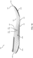
- an example of the sole structure 200, 200' is provided, and includes a main body 250, 250' and a plurality of the inserts 260, 260' cooperating to define the ground-engaging surface 202, 202' having a plurality of the channels 210, 210' formed therein.
- the main body 250' is formed of a first, foam material while the inserts 260' are formed of one or more rubber materials.
- the main body 250' defines a first region of the ground-engaging surface 202' and the one or more side surfaces 206' extending between the ground-engaging surface 202' and an upper surface 204 of the sole structure 200'.
- the inserts 260' of the sole structure 200' include an anterior insert 260a' disposed within an anterior socket 252a' of the main body 250', and a posterior insert 260b' disposed within a posterior socket 252b' of the main body.
- the anterior insert 260a' extends from the anterior end 18 to the ball region 12b, and from the lateral side 22 to the medial side 24.
- the anterior insert 260a' substantially defines the ground-engaging surface 202' in the toe portion 12 T of the forefoot region 12.
- the posterior insert 260b' extends from the posterior end 20 to an intermediate portion of the heel region 16, and extends from the lateral side 22 to the medial side.
- the intermediate portion of the heel region 16 may be defined by a transition between a convex portion of the ground-engaging surface 202', which extends forward from the posterior end 20, and a substantially flat portion of the ground-engaging surface 202', as illustrated in FIG. 9 . Accordingly, the main body 250' defines the ground-engaging surface 202' extending from the toe portion 12 T to the intermediate portion of the heel region 16, and interfaces with the anterior insert 260a' and the posterior insert 260b' at opposing ends, respectively.
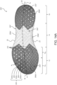
- the sole structure 200' includes a plurality of the channels 210, 210', 210a'-210j' formed therein. As shown in FIG. 8C , a first end channels 210', 210a' substantially defines a first end of the first region of the ground-engaging surface 202' and a second end channel 210b' substantially defines a second end of the first region of the ground-engaging surface 202', whereby sidewalls 256a', 256b' defining the respective sockets 252a', 252b' correspond with a profile of the respective end channels 210a', 210b'.
- Each of the first end channel 210a' and the second end channel 210b' include a plurality of serially-arranged segments 222 and extend along the lateral side surface 206a', the ground-engaging surface 202', and the medial side surface 206b'.
- the main body 250' of the sole structure 200' further includes a plurality of third channels 210c' formed adjacent to the first end channel 210a'.
- the third channels 210c' include serially-arranged segments 222 extending from the lateral side surface 206a' to the medial side surface 206b'.
- the segments 222 are arranged at alternating angles to each other to define a waveform or chevron pattern corresponding substantially to the shape of the first end channel 210a' such that the channels 210a', 210c' define a repeating chevron pattern extending in a direction along the longitudinal axis A F towards the posterior end 20.
- a plurality of fourth channels 210d' are formed adjacent the second channel 210b' and are spaced in the direction along the longitudinal axis A F towards the anterior end 18.
- the main body 250' of the sole structure 200' may further include a branched fifth channel 210e' extending from the lateral side surface 206a' to the medial side surface 206b'.
- the branched fifth channel 210e' includes a first sub-channel 210e 1 ' including of a series of segments 222 serially arranged at alternating angles to each other and extending from the lateral side surface 206a' to a junction 220 at an intermediate portion of the ground-engaging surface 202'.
- the branched channel 210e' is further defined by a pair of sub-channels 210e 2 ', 210e 3 ' diverging from the first sub-channel 210ei'at the intermediate portion of the ground-engaging surface 202' and each extending onto the medial side surface 206b'.
- the sole structure 200' includes a serpentine sixth channel 210f' disposed adjacent to the branched channel 210e' and extending from the lateral side surface 206a' to the medial side surface 206b', and including sub-channel 210f 1 ' having a plurality of segments 222 arranged in a serpentine configuration disposed in a central region of the ground-engaging surface 202'.
- the serpentine configuration of the sixth channel 210f' is defined by a first segment 222 extending from a first end node 224a to a second end node 224a at a first angle, a second segment 222 extending from the second end node 224a to a third end node 224a at a second angle substantially perpendicular to the first angle, a third segment 222 extending from the third end node 224a to a fourth end node 224a at the first angle, a fourth segment 222 extending from the fourth end node 224a to a fifth end node 224a at the second angle, a fifth segment 222 extending from the fifth end node 224a to a sixth end node 224a at the first angle, and a sixth segment 222 extending from the sixth end node 224a to a seventh end node 224a at the second angle, whereby the first, third, and fifth segments 222 are parallel to each other, with the fifth segment 222 being disposed intermediate the first segment 222 and
- the main body 250' of the sole structure 200' may further include a seventh channel 210h' having a horseshoe-like shape, whereby a first end and a second end of the seventh channel 210h' are both formed on the same side surface, and an intermediate portion of the channel extends onto the ground-engaging surface 202'.
- the anterior insert 260a' includes a plurality of eighth channels 210i' that are substantially complementary in shape to the first end channel 210a' of the main body 250'.
- the posterior insert 260b' includes a plurality of ninth channels 210j' that are substantially complementary to the second end channel 210b'. Accordingly, the eighth and ninth channels 210i', 210j' cooperate with the respective end channels 210a', 210b' to define a waveform-shaped interface between the sidewalls 256a' of the main body 250' and the peripheral surfaces 264a', 264b' of the inserts 260a', 260b'.
- the widths W c of the channels 210i', 210j' may taper from one side 22, 24 of the solestructure 200' to the other side 22, 24.
- the widths Wci of the nodes 224 may progressively decrease in a direction from the lateral side 22 to the medial side 24.
- the widths Wci of the nodes 224 may progressively increase in a direction from the lateral side 22 to the medial side 24.
- the channels 210i', 210j' of each of the inserts 260a', 260b' may include apertures 266 formed therethrough, which expose the underlying recessed surfaces 254a', 254b' of the main body 250'.
- the apertures 266 are formed through the nodes 224 of the channels 210i', 210j' and progressively decrease or increase in width (i.e. diameter) from one side 22, 24 to the other side 22, 24, similar to the nodes 224.
- the inserts 260' of the sole structure 200' are configured to provide regions of the ground-engaging surface 202' with increased traction and abrasion resistance relative to the main body 250'.
- the material forming the inserts 260' has a greater density than the material forming the main body 250' it is desirable to provide the inserts 260' only in regions of the ground-engaging surface 202' that are subjected to relatively high concentrations of force in order to provide a balance between the overall weight and desired performance of the sole structure 200'.
- the anterior insert 260a' and the posterior insert 260b' are configured to absorb greater forces associated with forward motion, while the main body 250' is configured to define the ground-engaging surface 202' in regions that are subjected to lesser forces than the inserts 260'.
- the sole structure 200, 200" includes a main body 250, 250" and a plurality of the inserts 260, 260" cooperating to define the ground-engaging surface 202, 202" having a plurality of the channels 210, 210" formed therein.
- the main body 250" is formed of a first, foam material, while the inserts 260" are formed of one or more rubber materials.
- the main body 250" defines a first region of the ground-engaging surface 202", and the one or more side surfaces 206" extending between the ground-engaging surface 202" and an upper surface 204 of the sole structure 200".
- the sole structure 200" includes an anterior insert 260a" disposed within an anterior socket 252a" of the main body 250" and a posterior insert 260b" disposed within a posterior socket 252b" of the main body 250".
- the anterior insert 260a" extends from the anterior end 18 to the midfoot region 14, and from the lateral side 22 to the medial side 24.
- the anterior insert 260a" substantially defines the ground-engaging surface 202" in the forefoot region 12 of the sole structure 200".
- the posterior insert 260b" extends from the posterior end 20 to the midfoot region 12, and extends from the lateral side 22 to the medial side 24. Accordingly, the posterior insert 260b" substantially defines the ground-engaging surface 202" in the heel region 16 of the sole structure 200".
- the main body 250" defines the ground-engaging surface 202" extending through the midfoot region 14, and interfaces with the anterior insert 260a" and the posterior insert 260b" at opposing ends, respectively.
- the sole structure 200' includes a plurality of the channels 210, 210", 210a"-210j" formed therein.
- a first end channel 210a" substantially defines a first end region of the ground-engaging surface 202" defined by the main body 250
- a second end channel 210b" substantially defines a second end of the region of the ground-engaging surface 202" defined by the main body 250" whereby sidewalls 256a", 256b" defining the respective sockets 252a", 252b" correspond with a profile of the respective end channels 210a", 210b".
- the first end channel 210a" is branched and comprises a plurality of sub-channels 210a 1-5 ".
- a first sub-channel 210ai" and a second sub-channel 210a 2 " are joined at a first junction 220 defined by a first end node 224a, and cooperate to define a profile of the sidewall 256a" of the anterior socket 252a".
- a third sub-channel 210a 3 " extends from the first junction 220 and is arranged in a serpentine configuration disposed in a central portion of the ground-engaging surface 202".
- the serpentine configuration is defined by a first segment 222 extending from a first end node 224a at the first junction 220 to a second end node 224a at a first angle with respect to the longitudinal axis A F , a second segment 222 extending from the second end node 224a to a third end node 224a at a second angle substantially perpendicular to the first angle, a third segment 222 extending from third end node 224a to a fourth end node 224a at the first angle, a fourth segment 222 extending from the fourth end node 224a to a fifth end node 224a at the second angle, and a fifth segment 222 extending from the sixth end node 224a to a seventh end node 224 at the first angle, whereby the third segment 222 is disposed between and parallel to the first segment 222 and the fifth segment 222.
- the seventh end node 224 of the third sub-channel 210a 3 defines a second junction 220 from which each of the fourth sub
- the second end channel 210b" includes a plurality of serially-arranged segments 222 and extends from the lateral side surface 206a", along the ground-engaging surface 202", and onto the medial side surface 206b".
- the main body 250" of the sole structure 200" further includes a third channel 210c" formed adjacent to the first end channel 210a".
- the third channel 210c" includes serially-arranged segments 222 extending from the lateral side surface 206a" to the medial side surface 206b".
- the segments 222 are arranged at alternating angles to each other to define a waveform or chevron pattern corresponding substantially to the profile of the first end channel 210a".
- the main body 250" of the sole structure 200" may further include a branched fourth channel 210", 210d" extending from the lateral side surface 206a" to the medial side surface 206b".
- the branched fourth channel 210d" includes a first sub-channel 210di" including of a series of segments 222 serially arranged at alternating angles to each other and extending from the medial side surface 206b" to an intermediate portion of the ground-engaging surface 202".
- the branched fourth channel 210d" is further defined by a pair of sub-channels 210d 2 ", 210d 2 " diverging from the first sub-channel 210di" at the intermediate portion of the ground-engaging surface 202" and each extending onto the lateral side surface 206a".
- the anterior insert 260a" includes a plurality of fifth channels 210e" extending between the lateral side 22 and the medial side 24 of the anterior insert 260a".
- a branched sixth channel 210f" is disposed adjacent to the plurality of the fifth channels 210e" and extends continuously between the lateral side 22 and the medial side 24.
- the branched sixth channel 210f" includes a first sub-channel 210fi" extending from the lateral side 22 to a junction 220 in an intermediate portion of the ground-engaging-surface 202", and a pair of sub-channels 210f 2 ", 210f 3 " diverging from the junction 220 and extending to the medial side 24 of the anterior insert 260a".
- the anterior insert 260a" further includes a seventh channel 210g" disposed intermediate the branched sixth channel 210f" and the first end channel 210a" of the main body 250".
- the seventh channel 210f' extends from the lateral side 22 of the anterior insert 260a" and intersects the first end channel 210a" formed in the main body 250".
- the posterior insert 260b' includes a plurality of eighth channels 210h" extending between the lateral side 22 and the medial side 24 of the posterior insert 260b'.
- a pair of ninth channels 210i" extend from the lateral side 22 of the posterior insert 260b" to terminal ends intermediate the longitudinal axis A F and the medial side 24.
- a tenth channel 210j" extends from the medial side 24 to a terminal end intermediate the longitudinal axis A F and the medial side 24
- the widths W c of the channels 210a"-210j" may taper from one side 22, 24 of the solestructure 200" to the other 22, 24.
- the widths Wci of the nodes 224 may progressively decrease in a direction from the lateral side 22 to the medial side 24.
- the widths Wci of the nodes 224 may progressively increase in a direction from the lateral side 22 to the medial side 24.
- the channels 210i"-210j" of each of the inserts 260a", 260b” may include apertures 266 formed therethrough, which expose the underlying recessed surfaces 254a", 254b" of the main body 250".
- the apertures 266 are formed through the nodes 224 of the channels 210e"-210j" and progressively decrease or increase in width (i.e. diameter) from one side 22, 24 to the other side 22, 24, similar to the nodes 224.
- the inserts 260" of the sole structure 200" are configured to provide areas of the ground-engaging surface 202" with increased traction and abrasion resistance.
- the material forming the inserts 260" has a greater density than the material forming the main body 250" it is desirable to provide the inserts 260" only in regions of the ground-engaging surface 202" that are subjected to relatively high concentrations of force in order to minimize overall weight of the sole structure 200".
- the anterior insert 260a" and the posterior insert 260b" are configured to absorb greater forces associated with forward and side-to-side motion, while the main body is configured to define regions of the ground-engaging surface 202" that are subjected to lesser forces than the regions defined by the inserts 260".
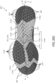
- FIG. 19-24 another example of the sole structure 200, 200′′′ is provided, and includes a main body 250, 250′′′ and a plurality of the inserts 260, 260′′′ cooperating to define the ground-engaging surface 202, 202′′′ having a plurality of the channels 210, 210′′′ formed therein.
- the main body 250′′′ is formed of a first, foam material while the inserts 260′′′ are formed of one or more rubber materials.
- the main body 250′′′ defines a first region of the ground-engaging surface 202′′′, and the one or more side surfaces 206′′′ extending between the ground-engaging surface 202′′′ and an upper surface 204 of the sole structure 200′′′.
- the sole structure 200′′′ includes an anterior insert 260a′′′ received within an anterior socket 252a′′′ of the main body 250′′′, a posterior insert 260b′′′ received within a posterior socket 252b′′′ of the main body 250′′′, a lateral insert 252c′′′ disposed within a lateral socket 252c′′′ of the main body 250′′′, and a medial insert 260d′′′ disposed within a medial socket 252d'".
- the anterior insert 260a" extends from the anterior end 18 to an intermediate portion of the forefoot region 12, and from the lateral side 22 to the medial side 24. Accordingly, the anterior insert 260a′′′ substantially defines the ground-engaging surface 202′′′ in the forefoot region 12 of the sole structure 200′′′.
- the posterior insert 260b′′′ extends from the posterior end 20 to an intermediate portion of the heel region 16, and extends from the lateral side 22 to the medial side 24. Accordingly, the posterior insert 260b′′′ substantially defines the ground-engaging surface 202′′′ in the heel region of the sole structure 200".
- the lateral insert 206c′′′ extends from a first side adjacent the lateral side 22 of the sole structure to a second side intermediate the lateral side 22 and the longitudinal axis A F , and from a first end opposing the anterior insert 260a′′′ to a second end at the midfoot region 12.
- the medial insert 206d′′′ extends from a first side adjacent the medial side 24 to a second side intermediate the medial side 24 and the longitudinal axis A F , and from a first end opposing the anterior insert 260a′′′ to a second end at the midfoot region 12.
- the inserts 260′′′ are all spaced apart from each other by the main body 250′′′.
- the sole structure 200' includes a plurality of the channels 210, 210′′′, 210a′′′-210j′′′ formed therein.
- a first end channel 210′′′, 210a′′′ substantially defines a first end of the first region of the ground-engaging surface 202′′′, thereby defining a profile of the interface between the peripheral surface 264a′′′ of the anterior insert 260a′′′ and the sidewall 256a′′′ of the anterior socket 252a'".
- the first end channel 210a′′′ extends continuously from the lateral side surface 206a′′′ to the medial side surface 206b′′′ along the main body 250′′′.
- a second end channel 210b′′′ substantially defines a second end of the first region of the ground-engaging surface 202′′′ defined by the main body 250′′′ and includes a first sub-channel 210b 1 ′′′ and a second sub-channel 210b 2 ′′′.
- the first sub-channel 210b 1 ′′′ extends from the lateral side surface 206a′′′ to a terminal end on the ground-engaging surface 202′′′, intermediate the longitudinal axis A F and the medial side 24.
- the second sub-channel 210b 2 ′′′ extends from the medial side surface 202b′′′ to a terminal end on the ground-engaging surface 202′′′, intermediate the longitudinal axis A F and the medial side 24. Accordingly, the second channel 210b′′′ may be described as including an interruption between the first sub-channel 210b 1 ′′′ and the second sub-channel 210b 2 ′′′.
- a third channel 210c′′′ is disposed adjacent to the first end channel 210a′′′ and extends continuously from the lateral side surface 206a′′′ to the medial side surface 206b′′′ along the ground-engaging surface 202′′′ and within the main body 250′′′. Accordingly, the third channel 210c′′′ substantially defines a profile of the interfaces between the peripheral surfaces 264c′′′, 264d′′′ of the lateral and medial inserts 260c′′′, 260d′′′ and the sidewalls 256c′′′, 256d′′′ of the lateral and medial sockets 252c′′′, 252d′′′.
- the third channel 210c′′′ defines the interfaces at the first ends of the lateral and medial inserts 260c′′′, 260d′′′. As shown, the interfaces have a substantially chevron-shaped profile corresponding a profile of the third channel 210c′′′.
- the sole structure 200′′′ includes a plurality of fourth channels 210d′′′ each extending continuously from the lateral side 22 to the medial side 24 and traversing the main body 250′′′ and at least one of the lateral insert 260c′′′ and the medial insert 260d′′′.
- at least one of the fourth channels 210d′′′ extends from the lateral side 22 along ground-engaging surface of the lateral insert 260c′′′, traverses a portion of the main body 250′′′ that separates the lateral insert 260c′′′ and the medial insert 260d′′′, and continues across the medial inert 260d′′′ to the medial side 24.
- Additional channels 210d′′′ may extend from the lateral side 22 along the lateral insert 260c′′′ and continue to the medial side 24 along the main body 250′′′, adjacent to the second end of the medial insert 260d′′′.
- the main body 250′′′ includes a branched fifth channel 210e′′′ including a serpentine sub-channel 210e 3 ′′′
- a first sub-channel 210e 1 ′′′ and a second sub-channel 210a 2 ′′′ are joined at a first junction 220 defined by a first end node 224a and cooperate to extend continuously from the lateral side surface 206a′′′ to the medial side surface 206b′′′.
- a third sub-channel 210e 3 ′′′ extends from the first junction 220 and is arranged in a serpentine configuration disposed in a central portion of the ground-engaging surface 202′′′.
- the serpentine configuration is defined by a first segment 222 extending from the first end node 224a at the first junction 220 to a second end node 224a at a first angle with respect to the longitudinal axis A F , a second segment 222 extending from the second end node 224a to a third end node 224a at a second angle substantially perpendicular to the first angle, a third segment 222 extending from the third end node 224a to a fourth end node 224a at the first angle, and a fourth segment extending from the fourth end node 224a, towards the first segment 222 at the second angle, and terminating at a fifth end node 224a intermediate the second segment 222 and the second sub-channel 210a 2′′′ .
- the main body 250′′′ further includes a pair of sixth channels 210f" disposed intermediate the second channel 210b′′′ and the branched fifth channel 210e'", and extending from the lateral side surface 206a′′′ to the medial side surface 206b′′′.
- a seventh channel 210g′′′ is disposed between the sixth channels 210f′′′ at the lateral side 22 of the sole structure 200′′′ and extends from a first end on the lateral side surface 206a′′′, onto the ground-engaging surface 202′′′, and back to a second end on the lateral side surface 206a′′′.
- An eighth channel 210h′′′ is disposed between the second end channel 210b′′′ and the pair of the sixth channels 210f′′′, and extends from the lateral side surface 206a′′′ to a terminal end on the ground-engaging surface 202′′′, intermediate the longitudinal axis A F and the medial side 24 of the sole structure 200′′′.
- the anterior insert 260a′′′ includes a plurality of ninth channels 210i′′′ formed therein and extending continuously from the lateral side 22 to the medial side 24. Profiles of the ninth channels 210i′′′ of the anterior insert 260a′′′ are complementary to a profile of the first end channel 210a′′′ and form a repeating chevron pattern along the anterior insert 260a'".
- the posterior insert 260b′′′ includes a plurality of tenth channels 210j′′′ formed therein and extending continuously from the lateral side 22 to the medial side 24. Profiles of the tenth channels 210j′′′ are complementary to a profile of the second end channel 210b′′′ and form a repeating chevron pattern along the posterior insert 260b ⁇
- the widths W c of the channels 210a′′′-210j′′′ may taper from one side 22, 24 of the solestructure 200′′′ to the other 22, 24.
- the widths Wci of the nodes 224 may progressively decrease in a direction from the lateral side 22 to the medial side 24.
- the widths Wci of the nodes 224 may progressively increase in a direction from the lateral side 22 to the medial side 24.
- each of the inserts 260a′′′, 260b′′′, and 260d′′′ may include apertures 266 formed therethrough, which expose the underlying recessed surfaces 254a′′′, 254b′′′, and 254d′′′ of the main body 250′′′.
- the anterior insert 260a′′′ includes apertures formed through the nodes 224 disposed substantially on the lateral side 24 of the sole structure
- the posterior insert 260b′′′ includes apertures formed through the nodes 224 disposed substantially on the medial side 24 of the sole structure 200′′′.
- all nodes 224 of the lateral insert 260c′′′ include apertures formed therethrough, while none of the nodes 224 of the medial insert 260d′′′ include apertures. Additionally or alternatively, all of the inserts 260′′′ may include apertures 266 formed through all of their nodes 224, or none of the inserts 260′′′ may include apertures 266.
- the inserts 260′′′ of the sole structure 200′′′ are configured to provide areas of the ground-engaging surface 202′′′ with increased traction and abrasion resistance.
- the material forming the inserts 260′′′ has a greater density than the material forming the main body 250′′′ it is desirable to provide the inserts 260′′′ only in regions of the ground-engaging surface 202′′′ that are subjected to relatively high concentrations of force.
- the anterior insert 260a′′′ and the posterior insert 260b′′′ are configured to absorb relatively high forces associated with forward running
- the lateral insert 260c′′′ and the medial insert 260d′′′ are configured to absorb relatively-high forces associated with side-to-side movements
- the main body 250′′′ is configured to define regions of the ground-engaging surface 202′′′ that are subjected to lesser forces than the regions defined by the inserts 260′′′.
- a sole structure for an article of footwear comprising a main body formed of a first material and defining a first portion of a ground-engaging surface including a first channel defined by a first segment extending along a first axis and a second segment extending along a second axis transverse to the first axis, and at least one insert formed of a second material and received by the main body, the at least one insert defining a second portion of the ground-engaging surface and having second channel including a third segment extending along a third axis parallel to the first axis and a fourth segment extending along a fourth axis transverse to the third axis and substantially parallel to the second axis, one of the first channel and the second channel defining an interface between the main body and the insert.
- Clause 2 The sole structure of Clause 1, wherein the at least one insert includes an anterior insert defining at least a portion of a forefoot region of the ground-engaging surface, and a posterior insert defining at least a portion of a heel region of the ground-engaging surface.
- Clause 3 The sole structure of Clause 2, wherein the anterior insert includes the second channel and the posterior insert includes a third channel having a fifth segment extending along a fifth axis substantially parallel to the first axis and a sixth segment extending along a sixth axis transverse to the fifth axis and substantially parallel to the second axis, the third channel defining an interface between the main body and the posterior insert.
- Clause 4 The sole structure of Clause 2, wherein the main body defines at least a portion of a midfoot region of the sole structure and separates the anterior insert from the posterior insert.
- Clause 5 The sole structure of Clause 1, wherein the main body is formed of a foam material and the at least one insert is formed of a rubber material.
- Clause 6 The sole structure of Clause 1, wherein the main body further defines at least one side surface of the sole structure, a portion of the first channel of the main body extending onto the side surface.
- Clause 7 The sole structure of Clause 6, wherein the at least one side surface of the sole structure includes a lateral side surface having a first portion of the first channel formed therein and a medial side surface having a second portion of the second channel formed therein.
- Clause 8 The sole structure of Clause 1, wherein the main body includes a socket defined by a recessed surface offset from the ground-engaging surface and a sidewall extending between the ground-engaging surface and the recessed surface and intersecting the at least one side surface to define a notch.
- Clause 9 The sole structure of Clause 8, wherein the insert is received by the socket, a first portion of a peripheral surface of the insert mating with the sidewall of the socket and a second portion of the peripheral surface of the insert being disposed in the notch and flush with the at least one side surface.
- Clause 10 The sole structure of Clause 1, wherein the first region of the ground-engaging surface is continuous and flush with the second region of the ground-engaging surface.
- a sole structure for an article of footwear comprising a main body defining a first region of a ground-engaging surface and at least one side surface extending from the ground-engaging surface, at least one insert received by the main body and defining a second region of the ground-engaging surface, and a first channel defined by a first plurality of segments including a first segment extending from a first node to a second node along a first axis, a second segment extending from a third node to a fourth node along a second axis transverse to the first axis, and a third segment extending from a fifth node to a sixth node along a third axis transverse to the second axis and substantially parallel to the first axis.
- Clause 12 The sole structure of Clause 11, wherein the first segment is formed along a first side surface, the second segment is formed in the first region of ground-engaging surface, and the third segment is formed along a second side surface.
- Clause 13 The sole structure of Clause 11, further comprising a second channel defined by a second plurality of segments including a fourth segment extending from a seventh node to an eighth node along a fourth axis substantially parallel to the first axis and a fifth segment extending from a ninth node to a tenth node along a fifth axis substantially parallel to the second axis.
- Clause 14 The sole structure of Clause 13, wherein the first channel is formed only in the main body of the sole structure and the second channel is formed only in the insert of the sole structure.
- Clause 15 The sole structure of Clause 14, wherein the insert includes an aperture through at least one of the nodes of the channel, the main body being exposed through the aperture.
- Clause 16 The sole structure of Clause 13, wherein a first portion of the first channel is formed in the main body and a second portion of the first channel is formed in the insert.
- Clause 17 The sole structure of Clause 13, wherein at least one of the segments includes an intermediate node.
- Clause 18 The sole structure of Clause 17 wherein widths of each of the first channel and the second channel is variable in a direction along at least one of the axes.
- Clause 19 The sole structure of Clause 11, wherein the second node and the third node define a first common node and the fourth node and the fifth node define a second common node, such that the first segment, the second segment, and the third segment are serially connected.
- Clause 20 The sole structure of Clause 11, wherein the second node, the third node, and the fifth node define a common node such that the second segment and the third segment define first and second sub-channels, respectively.
- a sole structure for an article of footwear comprising: a main body formed of a first material and defining a first region of a ground-engaging surface including a first channel defined by a first segment extending along a first axis and a second segment extending along a second axis transverse to the first axis; and at least one insert formed of a second material and received by the main body, the at least one insert defining a second region of the ground-engaging surface that is flush with the first region of the ground-engaging surface and having a second channel including a third segment extending along a third axis parallel to the first axis and a fourth segment extending along a fourth axis transverse to the third axis and substantially parallel to the second axis, one of the first channel and the second channel defining an interface between the main body and the insert.
- Item 2 The sole structure of Item 1, wherein the at least one insert includes an anterior insert defining at least a portion of a forefoot region of the ground-engaging surface, and a posterior insert defining at least a portion of a heel region of the ground-engaging surface.
- Item 3 The sole structure of Item 2, wherein the anterior insert includes the second channel and the posterior insert includes a third channel having a fifth segment extending along a fifth axis substantially parallel to the first axis and a sixth segment extending along a sixth axis transverse to the fifth axis and substantially parallel to the second axis, the third channel defining an interface between the main body and the posterior insert.
- Item 4 The sole structure of Item 2, wherein the main body defines at least a portion of a midfoot region of the sole structure and separates the anterior insert from the posterior insert.
- Item 5 The sole structure of Item 1, wherein the main body is formed of a foam material and the at least one insert is formed of a rubber material.
- Item 6 The sole structure of Item 1, wherein the main body further defines at least one side surface of the sole structure, a portion of the first channel of the main body extending along the side surface.
- Item 7 The sole structure of Item 6, wherein the at least one side surface of the sole structure includes a lateral side surface having a first portion of the first channel formed therein and a medial side surface having a second portion of the second channel formed therein.
- Item 8 The sole structure of Item 7, wherein the main body includes a socket defined by a recessed surface offset from the ground-engaging surface and a sidewall extending between the ground-engaging surface and the recessed surface and intersecting the at least one side surface.
- Item 9 The sole structure of Item 8, wherein the insert is received by the socket, a first portion of a peripheral surface of the insert mating with the sidewall of the socket and a second portion of the peripheral surface of the insert being flush with the at least one side surface.
- Item 10 The sole structure of Item 1, wherein a cross-section of the first channel is ellipsoidal and a cross-section of the second channel is polygonal.
- a sole structure for an article of footwear comprising: a main body defining a first region of a ground-engaging surface and at least one side surface extending from the ground-engaging surface; at least one insert received by the main body and defining a second region of the ground-engaging surface; and a first channel defined by a first plurality of segments including a first segment extending from a first node to a second node along a first axis, a second segment extending from a third node to a fourth node along a second axis transverse to the first axis, and a third segment extending from a fifth node to a sixth node along a third axis transverse to the second axis and substantially parallel to the first axis.
- Item 12 The sole structure of Item 11, wherein the first segment is formed along a first side surface, the second segment is formed in the first region of the ground-engaging surface, and the third segment is formed along a second side surface.
- Item 13 The sole structure of Item 11, further comprising a second channel defined by a second plurality of segments including a fourth segment extending from a seventh node to an eighth node along a fourth axis substantially parallel to the first axis and a fifth segment extending from a ninth node to a tenth node along a fifth axis substantially parallel to the second axis.
- Item 14 The sole structure of Item 13, wherein the first channel is formed only in the main body of the sole structure and the second channel is formed only in the insert of the sole structure.
- Item 15 The sole structure of Item 14, wherein the insert includes an aperture through at least one of the nodes of the second channel, the main body being exposed through the aperture.
- Item 16 The sole structure of Item 13, wherein a first portion of the first channel is formed in the main body and a second portion of the first channel is formed in the insert.
- Item 17 The sole structure of Item 13, wherein at least one of the segments includes an intermediate node.
- Item 18 The sole structure of Item 17 wherein widths of each of the first channel and the second channel are variable in a direction along at least one of the axes.
- Item 19 The sole structure of Item 11, wherein the second node and the third node define a first common node and the fourth node and the fifth node define a second common node, such that the first segment, the second segment, and the third segment are serially connected.
- Item 20 The sole structure of Item 11, wherein the second node, the third node, and the fifth node define a common node such that the second segment and the third segment define first and second sub-channels, respectively.
Landscapes
- Chemical & Material Sciences (AREA)
- Engineering & Computer Science (AREA)
- Materials Engineering (AREA)
- Health & Medical Sciences (AREA)
- General Health & Medical Sciences (AREA)
- Physical Education & Sports Medicine (AREA)
- Footwear And Its Accessory, Manufacturing Method And Apparatuses (AREA)
Abstract
Description
- This application is a
PCT International Application claiming priority to U.S. Application Serial No. 15/878,095, filed January 23, 2018 - The present disclosure relates generally to sole structures for articles of footwear and more particularly to sole structures incorporating a composite ground-contacting surface.
- This section provides background information related to the present disclosure, which is not necessarily prior art.
- Articles of footwear conventionally include an upper and a sole structure. The upper may be formed from any suitable material(s) to receive, secure, and support a foot on the sole structure. The upper may cooperate with laces, straps, or other fasteners to adjust the fit of the upper around the foot. A bottom portion of the upper, proximate to a bottom surface of the foot, attaches to the sole structure.
- Sole structures generally include a layered arrangement extending between a ground surface and the upper. One layer of the sole structure includes an outsole that provides abrasionresistance and traction with the ground surface. The outsole may be formed using materials and geometries that impart durability and wear-resistance, as well as enhance traction with the ground surface. Another layer of the sole structure includes a midsole disposed between the outsole and the upper. The midsole provides cushioning for the foot and may be partially formed from a polymer foam material that compresses resiliently under an applied load to cushion the foot by attenuating ground-reaction forces. The midsole may additionally or alternatively incorporate a fluid-filled bladder to increase durability of the sole structure, as well as to provide cushioning to the foot by compressing resiliently under an applied load to attenuate ground-reaction forces. Sole structures may also include a comfort-enhancing insole or a sockliner located within a void proximate to the bottom portion of the upper and a strobel attached to the upper and disposed between the midsole and the insole or sockliner.
- The drawings described herein are for illustrative purposes only of selected configurations and are not intended to limit the scope of the present disclosure.
-
FIG. 1 is a side perspective view of an article of footwear in accordance with principles of the present disclosure; -
FIG. 2 is a lateral-side elevation view of the article of footwear ofFIG. 1 ; -
FIG. 3 is a medial-side elevation view of the article of footwear ofFIG. 1 ; -
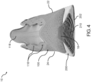
FIG. 4 is a front elevation view of the article of footwear ofFIG. 1 ; -
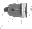
FIG. 5 is a rear elevation view of the article of footwear ofFIG. 1 ; -
FIG. 6 is a top view of the article of footwear ofFIG. 1 ; -
FIG. 7 is a bottom perspective view of a sole structure of the article of footwear ofFIG. 1 , showing a geometry and configuration of a plurality of segments associated with a ground-contacting surface of a sole structure; -
FIGS. 8A-8C are bottom views of the sole structure ofFIG. 7 ; -
FIG. 9 is a lateral-side elevation view of the sole structure ofFIG. 7 ; -
FIG. 10 is a medial-side elevation view of the sole structure ofFIG. 7 ; -
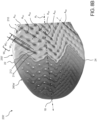
FIG. 11 is a front elevation view of the sole structure ofFIG. 7 ; -
FIG. 12 is a rear elevation view of the sole structure ofFIG. 7 ; -
FIG. 13 is a bottom perspective view of a sole structure of the article of footwear ofFIG. 1 , showing a geometry and configuration of a plurality of segments associated with a ground-contacting surface of a sole structure; -
FIGS. 14A-14C are bottom views of the sole structure ofFIG. 13 ; -
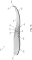
FIG. 15 is a lateral-side elevation view of the sole structure ofFIG. 13 ; -
FIG. 16 is a medial-side elevation view of the sole structure ofFIG. 13 ; -
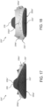
FIG. 17 is a front elevation view of the sole structure ofFIG. 13 ; -
FIG. 18 is a rear elevation view of the sole structure ofFIG. 13 ; -
FIG. 19 is a bottom perspective view of a sole structure of the article of footwear ofFIG. 1 , showing a geometry and configuration of a plurality of segments associated with a ground-contacting surface of a sole structure; -
FIGS. 20A-20C are bottom views of the sole structure ofFIG. 19 ; -
FIG. 21 is a lateral-side elevation view of the sole structure ofFIG. 19 ; -
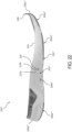
FIG. 22 is a medial-side elevation view of the sole structure ofFIG. 19 ; -
FIG. 23 is a front elevation view of the sole structure ofFIG. 19 ; and -
FIG. 24 is a rear elevation view of the sole structure ofFIG. 19 . - Corresponding reference numerals indicate corresponding parts throughout the drawings.
- Example configurations will now be described more fully with reference to the accompanying drawings. Example configurations are provided so that this disclosure will be thorough, and will fully convey the scope of the disclosure to those of ordinary skill in the art. Specific details are set forth such as examples of specific components, devices, and methods, to provide a thorough understanding of configurations of the present disclosure. It will be apparent to those of ordinary skill in the art that specific details need not be employed, that example configurations may be embodied in many different forms, and that the specific details and the example configurations should not be construed to limit the scope of the disclosure.
- The terminology used herein is for the purpose of describing particular exemplary configurations only and is not intended to be limiting. As used herein, the singular articles "a," "an," and "the" may be intended to include the plural forms as well, unless the context clearly indicates otherwise. The terms "comprises," "comprising," "including," and "having," are inclusive and therefore specify the presence of features, steps, operations, elements, and/or components, but do not preclude the presence or addition of one or more other features, steps, operations, elements, components, and/or groups thereof. The method steps, processes, and operations described herein are not to be construed as necessarily requiring their performance in the particular order discussed or illustrated, unless specifically identified as an order of performance. Additional or alternative steps may be employed.
- When an element or layer is referred to as being "on," "engaged to," "connected to," "attached to," or "coupled to" another element or layer, it may be directly on, engaged, connected, attached, or coupled to the other element or layer, or intervening elements or layers may be present. In contrast, when an element is referred to as being "directly on," "directly engaged to," "directly connected to," "directly attached to," or "directly coupled to" another element or layer, there may be no intervening elements or layers present. Other words used to describe the relationship between elements should be interpreted in a like fashion (e.g., "between" versus "directly between," "adjacent" versus "directly adjacent," etc.). As used herein, the term "and/or" includes any and all combinations of one or more of the associated listed items.
- The terms first, second, third, etc. may be used herein to describe various elements, components, regions, layers and/or sections. These elements, components, regions, layers and/or sections should not be limited by these terms. These terms may be only used to distinguish one element, component, region, layer or section from another region, layer or section. Terms such as "first," "second," and other numerical terms do not imply a sequence or order unless clearly indicated by the context. Thus, a first element, component, region, layer or section discussed below could be termed a second element, component, region, layer or section without departing from the teachings of the example configurations.
- One aspect of the disclosure provides a sole structure for an article of footwear. The sole structure includes a main body formed of a first material and defining a first portion of a ground-engaging surface. The main body includes a first channel defined by a first segment extending along a first axis and a second segment extending along a second axis transverse to the first axis. The sole structure also includes at least one insert formed of a second material and received by the main body. The at least one insert defines a second portion of the ground-engaging surface that is flush with the first region of the ground-engaging surface and has a second channel including a third segment extending along a third axis parallel to the first axis and a fourth segment extending along a fourth axis transverse to the third axis and substantially parallel to the second axis. One of the first channel and the second channel defines an interface between the main body and the insert.
- Implementations of the disclosure may include one or more of the following optional features. In some implementations, the at least one insert includes an anterior insert defining at least a portion of a forefoot region of the ground-engaging surface, and a posterior insert defining at least a portion of a heel region of the ground-engaging surface. Here, the anterior insert may include the second channel and the posterior insert may include a third channel having a fifth segment extending along a fifth axis substantially parallel to the first axis and a sixth segment extending along a sixth axis transverse to the fifth axis and substantially parallel to the second axis, the third channel defining an interface between the main body and the posterior insert. Additionally or alternatively, the main body may define at least a portion of a midfoot region of the sole structure and may separate the anterior insert from the posterior insert.
- In some examples, the main body is formed of a foam material and the at least one insert is formed of a rubber material. The main body may define at least one side surface of the sole structure, a portion of the first channel of the main body extending onto the side surface. Here, the at least one side surface of the sole structure may include a lateral side surface having a first portion of the first channel formed therein and a medial side surface having a second portion of the second channel formed therein.
- In some configurations, the main body includes a socket defined by a recessed surface offset from the ground-engaging surface and a sidewall extending between the ground-engaging surface and the recessed surface and intersecting the at least one side surface to define a notch. In this configuration, the insert is received by the socket, a first portion of a peripheral surface of the insert mating with the sidewall of the socket and a second portion of the peripheral surface of the insert being disposed in the notch and flush with the at least one side surface. In some examples, the first region of the ground-engaging surface is continuous and flush with the second region of the ground-engaging surface.
- Another aspect of the disclosure provides a sole structure for an article of footwear. The sole structure includes a main body defining a first region of a ground-engaging surface and at least one side surface extending from the ground-engaging surface. The sole structure also includes at least one insert received by the main body, which defines a second region of the ground-engaging surface. The sole structure further includes a first channel defined by a first plurality of segments including a first segment extending from a first node to a second node along a first axis, a second segment extending from a third node to a fourth node along a second axis transverse to the first axis, and a third segment extending from a fifth node to a sixth node along a third axis transverse to the second axis and substantially parallel to the first axis.
- Implementations of the disclosure may include one of more of the following optional features. In some implementations, the first segment is formed along a first side surface, the second segment is formed in the first region of the ground-engaging surface, and the third segment is formed along a second side surface.
- In some examples, the sole structure includes a second channel defined by a second plurality of segments including a fourth segment extending from a seventh node to an eighth node along a fourth axis substantially parallel to the first axis and a fifth segment extending from a ninth node to a tenth node along a fifth axis substantially parallel to the second axis. Here, the first channel may be formed only in the main body of the sole structure and the second channel may be formed only in the insert of the sole structure. The insert may include an aperture through at least one of the nodes of the channel, such that the main body is exposed through the aperture. A first portion of the first channel may be formed in the main body and a second portion of the first channel is formed in the insert. At least one of the segments may include an intermediate node. Here, widths of each of the first channel and the second channel may be variable in a direction along at least one of the axes.
- In some configurations, the second node and the third node define a first common node and the fourth node and the fifth node define a second common node, such that the first segment, the second segment, and the third segment are serially connected. Alternatively, the second node, the third node, and the fifth node may define a common node such that the second segment and the third segment define first and second sub-channels, respectively.
- Referring to
FIGS. 1-6 , an article offootwear 10 includes an upper 100 andsole structure 200. The article offootwear 10 may be divided into one or more regions. The regions may include aforefoot region 12, amid-foot region 14, and aheel region 16. Theforefoot region 12 may be subdivided into atoe portion 12T corresponding with phalanges and aball region 12B associated with metatarsal bones of a foot. Themid-foot region 14 may correspond with an arch area of the foot, and theheel region 16 may correspond with rear portions of the foot, including a calcaneus bone. Thefootwear 10 may further include ananterior end 18 associated with a forwardmost point of theforefoot region 12, and aposterior end 20 corresponding to a rearward-most point of theheel region 16. A longitudinal axis AF of thefootwear 10 extends along a length of thefootwear 10 from theanterior end 18 to theposterior end 20, and generally divides thefootwear 10 into alateral region 22 and amedial region 24. Accordingly, thelateral region 22 and themedial region 24 respectively correspond with opposite sides of thefootwear 10 and extend through theregions FIGS. 8 ,14 , and20 , the longitudinal axis AF of the footwear may be arcuate in shape, such that the longitudinal axis AF is substantially centrally located between thelateral side 22 and themedial side 24 along the length of thefootwear 10. - The upper 100 includes interior surfaces that define an
interior void 102 configured to receive and secure a foot for support onsole structure 200. The upper 100 may be formed from one or more materials that are stitched or adhesively bonded together to form theinterior void 102. Suitable materials of the upper may include, but are not limited to, mesh, textiles, foam, leather, and synthetic leather. The materials may be selected and located to impart properties of durability, air-permeability, wear-resistance, flexibility, and comfort. - In some examples, the upper 100 includes a strobel (not shown) having a bottom surface opposing the
sole structure 200 and an opposing top surface defining a footbed 108 of theinterior void 102. Stitching or adhesives may secure the strobel to the upper 100. The footbed 108 may be contoured to conform to a profile of the bottom surface (e.g., plantar) of the foot. Optionally, the upper 100 may also incorporate additional layers such as an insole 110 or sockliner that may be disposed upon the strobel and reside within theinterior void 102 of the upper 100 to receive a plantar surface of the foot to enhance the comfort of the article offootwear 10. An ankle opening 112 in theheel region 16 may provide access to theinterior void 102. For example, the ankle opening 112 may receive a foot to secure the foot within thevoid 102 and facilitate entry and removal of the foot from and to theinterior void 102. - In some examples, one or more fasteners (not shown) extend along the upper 100 to adjust a fit of the
interior void 102 around the foot and to accommodate entry and removal of the foot therefrom. The upper 100 may includeapertures 116 such as eyelets and/or other engagement features such as fabric or mesh loops that receive the fasteners. The fasteners may include laces, straps, cords, hook-and-loop, or any other suitable type of fastener. The upper 100 may include atongue portion 118 that extends between theinterior void 102 and the fasteners. - With reference to
FIGS. 7-24 , several alternative implementations of asole structure 200 according to the instant disclosure are provided. In view of the substantial similarities in structure and function of the components associated with each of the implementations, like reference numerals are used hereinafter and in the drawings to identify common components having the same design. Like reference numerals containing letter extensions are used to identify variations of common components within an implementation of thesole structure 200, while reference numerals containing prime symbols (') are used to identify examples of common components that have been modified between implementations and reference numerals containing subscripts are used to identify sub-components of a parent component. Accordingly, reference to components using numerals not including letter extensions, prime symbols, or subscripts is understood to collectively refer to all variations of a common component including like reference numerals, including those examples having letter extensions, prime symbols, and/or subscripts. - With reference to
FIGS. 7-24 , thesole structure 200, 200'-200‴ includes a ground-engagingsurface 202, 202'-202‴ configured to interface with a ground surface when the article offootwear 10 is worn by a user. Thesole structure 200 is further defined by anupper surface 204, which is formed on an opposite side of thesole structure 200 from the ground-engagingsurface 202 and is configured to oppose the upper, thereby providing a foot-support surface. A side surface 206, 206'-206‴ extends between the ground-engagingsurface 202 and theupper surface 204, and defines an outer periphery of thesole structure 200. Although the illustratedsole structure 200 includes a substantially continuous, contoured side surface 206 extending around the entire periphery of thesole structure 200, it may be defined as comprising alateral side surface lateral side 22 of thesole structure 200, amedial side surface medial side 24 of thesole structure 200, ananterior side surface 206c, 206'-206‴ extending around theforefoot region 12 between thelateral side surface 206a and themedial side surface 206b, and aposterior side surface heel region 16 between thelateral side surface 206a and themedial side surface 206b. Theanterior side surface 206c may be defined by a toe cap, ortab 208, which protrudes from theupper surface 204 and is configured to attach or bond to the upper 100 at theanterior end 18. - A
transition 209 may be formed at the intersection of the ground-engagingsurface 202 and the side surface 206, and may be defined by a variable radius RT, RT1, RT2 extending around the periphery of thesole structure 200. For example, in theforefoot region 12 and theheel region 14 thetransition 209 may be defined by a first radius RT1 providing a relativelypronounced transition 209 between the ground-engagingsurface 202 and the side surface 206. Conversely, thetransition 209 between the ground-engagingsurface 202 and the side surface 206 in themid-foot region 14 may be defined by a relatively large radius RT2, whereby the ground-engagingsurface 202 and the side surface 206 are substantially continuously formed. - The
sole structure 200 further includes a plurality ofchannels 210, 210'-210‴ formed therein. Thechannels 210 are defined by a recessedsurface 212 offset from the ground-engagingsurface 202 by a depth Dc, and an opposing pair ofsidewalls 214 extending from the ground-engagingsurface 202 to the recessedsurface 212. A distance between thesidewalls 214 defines a width Wc of thechannels 210, as shown inFIGS. 8C ,14C , and20C . As described in greater detail below, the depths Dc and the widths Wc of thechannels 210 may be variable along lengths of thechannels 210. - Each of the
channels 210 includes a plurality ofelongate segments 222. Each of thesegments 222 includes two ormore nodes 224 connected to each other by intermediatenecked regions 226, and extends from afirst end node 224a to asecond end node 224a along a longitudinal segment axis As, as shown inFIG. 8A . One or more of thesegments 222 may further includeintermediate nodes 224b disposed between theend nodes 224a along the segment axis As, and interconnected to each other by thenecked regions 226. Accordingly, theend nodes 224a, theintermediate nodes 224b, and thenecked regions 226 of arespective segment 222 are all aligned along a common segment axis As. With reference toFIG. 8B ,14B , and20B , the segment axes AS1-n of each of thesegments 222 may be arranged at oblique angles with respect to the longitudinal axis AF of thefootwear 10. - As discussed above, the width Wc of each of the
channels 210 is variable along a length of thechannels 210. More specifically, the width Wc is variable along eachsegment 222, whereby a first width WC1 of thesegment 222 at thenodes 224 is greater than a second width WC2 of thesegment 222 at each of thenecked regions 226, as shown inFIGS. 8B ,14B , and20B . Alternatively, thesidewalls 214 may be described as having an undulated shape, whereby thesidewalls 214 of eachsegment 222 converge with each other through thenecked regions 226 and diverge through thenodes 224. - The
segments 222 of eachchannel 210 may be serially arranged at alternating oblique or right angles to each other. Accordingly the segment axes AS1-n of connected ones of thesegments 222 are transverse to each other and define a waveform or chevron shape, as shown inFIGS. 8B ,14B , and20B . One or more of thechannels 210 may define a single, continuous path, whereby thesegments 222 are serially arranged in an end-to-end arrangement. For example, afirst segment 222 may extend from afirst end node 224a to asecond end node 224a along a first segment axis Asi, and asecond segment 222 may extend from thesecond end node 224a to athird end node 224a along a second segment axis AS2 at an oblique or right angle with respect to the first segment axis Asi. Further, athird segment 222 may extend from thethird end node 224a to afourth end node 224a along a third segment axis Ass at an oblique or right angle to the second segment axis AS2 and substantially parallel (e.g. within approximately 5 degrees) to the first segment axis Asi. In addition or alternative to serially-arrangedchannels 210, thesole structure 200 may include branchedchannels 210, whereby three or more sub-channels 210 diverge from acommon end node 224a defining ajunction 220. In some examples, one ormore channels 210 may include serpentine portions, wherein one ormore segments 222 of a channel is disposed between two or more other segments of achannel 210, as described below. - In some implementations, the
sole structure 200 may be compositely formed of amain body 250, 250'-250‴ and one ormore inserts 260, 260'-260‴, which cooperate to define the ground-engagingsurface 202 of thesole structure 200. As discussed in greater detail below, themain body 250 includes one or more sockets 252, 252'-252‴ each configured to receive a corresponding one of theinserts 260, thereby allowing regions of the ground-engagingsurface 202 and side surfaces 206 defined by theinserts 260 to be flush with regions of the ground-engagingsurface 202 and side surfaces 206 defined by themain body 250. Interfaces between theinserts 260 and themain body 250 may be defined by thechannels 210, such that an interface between aninsert 260 and themain body 250 has a profile substantially similar to a profile of the one of thechannels 210. Additionally or alternatively, themain body 250 and theinserts 260 may cooperate to define thechannels 210 of thesole structure 200, whereby one or more of thechannels 210 may extend substantially uninterrupted between themain body 250 and the one or more inserts 260. - With reference to
FIGS. 7 ,13 , and19 , each of the sockets 252 is defined by a recessed surface 254, 254'-254‴ (hidden) offset from the ground-engagingsurface 202 of the main body by a depth Ds. At least a portion of an outer periphery of each of the sockets 252 is defined by one or more sidewalls 256, 256'-256‴ extending between the recessed surface 254 and the ground-engagingsurface 202. The sidewall 256 of the socket 252 may intersect one or more of the side surfaces 206 of thesole structure 200, thereby defining an opening (not shown) or notch through the side surface(s) 206. - The
inserts 260 are configured to be received within the sockets 252 of themain body 250. Accordingly, theinserts 260 are defined by an inner surface 262, 262'-262‴ (hidden) opposing the ground-engagingsurface 202 and aperipheral surface 264, 264'-264‴ extending between the inner surface 262 and the ground-engagingsurface 202. A distance between the ground-engagingsurface 202 and the inner surface 262 defines a thickness TI of each of theinserts 260, which is substantially similar to the depth Ds of the corresponding socket 252, such that the region of the ground-engagingsurface 202 defined by theinsert 260 is substantially aligned or coplanar with the regions of the ground-engagingsurface 202 defined by themain body 250. - A profile of the
peripheral surface 264 of eachinsert 260 corresponds to a profile defined by the sidewalls 256 and opening of the corresponding socket 252. Accordingly, theperipheral surface 264 of theinsert 260 mates with the sidewall 256 of the socket 252 to provide a continuous and uninterrupted transition between themain body 250 and theinsert 260 along the ground-engagingsurface 202. Further the portions of theperipheral surface 264 extending along the opening of the socket 252 are substantially flush with the corresponding side surfaces 206 defined by themain body 250 to provide a continuous and uninterrupted transition between themain body 250 and theinsert 260 along the side surfaces 206. - As shown, the
main body 250 defines theupper surface 204 and the side surfaces 206 of thesole structure 200, and further defines one or more regions of the ground-engagingsurface 202. Accordingly, themain body 250 is configured to provide the functions of both a traditional midsole as well as an outsole, and may be formed of a molded foam material providing a range of desirable properties, including durability, energy return, cushioning, traction, and support. Examples of suitable materials are disclosed in U.S. Patent Application Publication NumbersUS 2017/0267845 ,US 2017/0267846 ,US 2017/0267847 ,US 2017/0267848 ,US 2017/0267849 , andUS 2017/0267850 , which are hereby incorporated by reference in their entirety. - The
inserts 260 are generally located in regions of the ground-engagingsurface 202 that are more likely to be subjected to increased point loads relative to the regions of the ground-engagingsurface 202 defined by the foam material of themain body 250. Accordingly, theinserts 260 are formed of a material having a greater coefficient of friction, durability, and abrasion resistance than the material of themain body 250. - As discussed above, the
channels 210 of thesole structure 200 may extend continuously along the ground-engagingsurface 202. Accordingly, one or more of thechannels 210 may traverse both themain body 250 and one or more of theinserts 260 in a substantially continuous, and uninterrupted manner. For example, a first one of thesegments 222 may be formed in one of theinserts 260, and may connect to a second one of thesegments 222 formed in themain body 250. Additionally or alternatively, a single one of thesegments 222 may extend from themain body 250 to theinsert 260, or vice versa. - As shown in
FIGS. 7 ,13 , and19 , the portions of thechannels 210 defined by themain body 250 may be formed with "softer" edges than the portions of thechannels 210 defined by the inserts. For example, the edges formed by the intersection of the recessedsurface 212 and thesidewalls 214 of thechannels 210 may have a greater radius in themain body 250 than in theinserts 260. In some examples, the recessedsurface 212 and thesidewalls 214 defining thechannels 210 formed in themain body 250 may be substantially continuous and definechannels 210 having semi-ellipsoidal cross sections. Conversely, the recessedsurface 212 and thesidewalls 214 defining the channels formed in the inserts may intersect to definechannels 210 having polygonal (e.g. rectangular) cross sections. - The distinction in channel definition between the
main body 250 and theinserts 260 is configured to maximize traction and to minimize abrasion of the ground-engagingsurface 202. For example, although themain body 250 is formed of a durable foam material, it may exhibit lower resistance to abrasion than the material forming theinserts 260. By providing "softened" edges, thechannels 210 are less likely to be subjected to concentrations of high load and abrasion, thereby improving durability. Conversely, theinserts 260 are formed of a material having a relatively higher abrasion resistance. Accordingly, thechannels 210 of theinserts 260 may be formed with "harder" edges to provide improved traction, especially on soft ground surfaces. - With reference to
FIG. 7-12 , an example of thesole structure 200, 200' is provided, and includes amain body 250, 250' and a plurality of theinserts 260, 260' cooperating to define the ground-engagingsurface 202, 202' having a plurality of thechannels 210, 210' formed therein. As discussed hereinabove, the main body 250' is formed of a first, foam material while the inserts 260' are formed of one or more rubber materials. - As shown in
FIGS. 7 and8 , the main body 250' defines a first region of the ground-engaging surface 202' and the one or more side surfaces 206' extending between the ground-engaging surface 202' and anupper surface 204 of the sole structure 200'. - In the illustrated example, the inserts 260' of the sole structure 200' include an
anterior insert 260a' disposed within ananterior socket 252a' of the main body 250', and aposterior insert 260b' disposed within aposterior socket 252b' of the main body. As shown inFIGS. 7-9 , theanterior insert 260a' extends from theanterior end 18 to the ball region 12b, and from thelateral side 22 to themedial side 24. Accordingly, theanterior insert 260a' substantially defines the ground-engaging surface 202' in thetoe portion 12T of theforefoot region 12. Theposterior insert 260b' extends from theposterior end 20 to an intermediate portion of theheel region 16, and extends from thelateral side 22 to the medial side. The intermediate portion of theheel region 16 may be defined by a transition between a convex portion of the ground-engaging surface 202', which extends forward from theposterior end 20, and a substantially flat portion of the ground-engaging surface 202', as illustrated inFIG. 9 . Accordingly, the main body 250' defines the ground-engaging surface 202' extending from thetoe portion 12T to the intermediate portion of theheel region 16, and interfaces with theanterior insert 260a' and theposterior insert 260b' at opposing ends, respectively. - The sole structure 200' includes a plurality of the
channels FIG. 8C , afirst end channels 210', 210a' substantially defines a first end of the first region of the ground-engaging surface 202' and asecond end channel 210b' substantially defines a second end of the first region of the ground-engaging surface 202', whereby sidewalls 256a', 256b' defining therespective sockets 252a', 252b' correspond with a profile of therespective end channels 210a', 210b'. Each of thefirst end channel 210a' and thesecond end channel 210b' include a plurality of serially-arrangedsegments 222 and extend along thelateral side surface 206a', the ground-engaging surface 202', and themedial side surface 206b'. - The main body 250' of the sole structure 200' further includes a plurality of
third channels 210c' formed adjacent to thefirst end channel 210a'. Thethird channels 210c' include serially-arrangedsegments 222 extending from thelateral side surface 206a' to themedial side surface 206b'. Thesegments 222 are arranged at alternating angles to each other to define a waveform or chevron pattern corresponding substantially to the shape of thefirst end channel 210a' such that thechannels 210a', 210c' define a repeating chevron pattern extending in a direction along the longitudinal axis AF towards theposterior end 20. Similarly, a plurality offourth channels 210d' are formed adjacent thesecond channel 210b' and are spaced in the direction along the longitudinal axis AF towards theanterior end 18. - The main body 250' of the sole structure 200' may further include a branched
fifth channel 210e' extending from thelateral side surface 206a' to themedial side surface 206b'. The branchedfifth channel 210e' includes afirst sub-channel 210e1' including of a series ofsegments 222 serially arranged at alternating angles to each other and extending from thelateral side surface 206a' to ajunction 220 at an intermediate portion of the ground-engaging surface 202'. Thebranched channel 210e' is further defined by a pair of sub-channels 210e2', 210e3' diverging from the first sub-channel 210ei'at the intermediate portion of the ground-engaging surface 202' and each extending onto themedial side surface 206b'. - With continued reference to
FIG. 8C , the sole structure 200' includes a serpentinesixth channel 210f' disposed adjacent to thebranched channel 210e' and extending from thelateral side surface 206a' to themedial side surface 206b', and including sub-channel 210f1' having a plurality ofsegments 222 arranged in a serpentine configuration disposed in a central region of the ground-engaging surface 202'. The serpentine configuration of thesixth channel 210f' is defined by afirst segment 222 extending from afirst end node 224a to asecond end node 224a at a first angle, asecond segment 222 extending from thesecond end node 224a to athird end node 224a at a second angle substantially perpendicular to the first angle, athird segment 222 extending from thethird end node 224a to afourth end node 224a at the first angle, afourth segment 222 extending from thefourth end node 224a to afifth end node 224a at the second angle, afifth segment 222 extending from thefifth end node 224a to asixth end node 224a at the first angle, and asixth segment 222 extending from thesixth end node 224a to aseventh end node 224a at the second angle, whereby the first, third, andfifth segments 222 are parallel to each other, with thefifth segment 222 being disposed intermediate thefirst segment 222 and thethird segment 222. Likewise, the second, fourth, andsixth segments 222 are parallel to each other, with thefourth segment 222 being disposed between thesecond segment 222 and thesixth segment 222. - The main body 250' of the sole structure 200' may further include a
seventh channel 210h' having a horseshoe-like shape, whereby a first end and a second end of theseventh channel 210h' are both formed on the same side surface, and an intermediate portion of the channel extends onto the ground-engaging surface 202'. - With continued reference to
FIG. 8C , theanterior insert 260a' includes a plurality ofeighth channels 210i' that are substantially complementary in shape to thefirst end channel 210a' of the main body 250'. Likewise, theposterior insert 260b' includes a plurality ofninth channels 210j' that are substantially complementary to thesecond end channel 210b'. Accordingly, the eighth andninth channels 210i', 210j' cooperate with therespective end channels 210a', 210b' to define a waveform-shaped interface between the sidewalls 256a' of the main body 250' and theperipheral surfaces 264a', 264b' of theinserts 260a', 260b'. - The widths Wc of the
channels 210i', 210j' may taper from oneside other side anterior insert 260a', the widths Wci of thenodes 224 may progressively decrease in a direction from thelateral side 22 to themedial side 24. Conversely, in theposterior insert 260b', the widths Wci of thenodes 224 may progressively increase in a direction from thelateral side 22 to themedial side 24. Thechannels 210i', 210j' of each of theinserts 260a', 260b' may includeapertures 266 formed therethrough, which expose the underlying recessedsurfaces 254a', 254b' of the main body 250'. In the illustrated example, theapertures 266 are formed through thenodes 224 of thechannels 210i', 210j' and progressively decrease or increase in width (i.e. diameter) from oneside other side nodes 224. - As discussed above, the inserts 260' of the sole structure 200' are configured to provide regions of the ground-engaging surface 202' with increased traction and abrasion resistance relative to the main body 250'. However, because the material forming the inserts 260' has a greater density than the material forming the main body 250' it is desirable to provide the inserts 260' only in regions of the ground-engaging surface 202' that are subjected to relatively high concentrations of force in order to provide a balance between the overall weight and desired performance of the sole structure 200'. For example, in the example of the sole structure 200' shown in
FIGS. 7-12 theanterior insert 260a' and theposterior insert 260b' are configured to absorb greater forces associated with forward motion, while the main body 250' is configured to define the ground-engaging surface 202' in regions that are subjected to lesser forces than the inserts 260'. - With reference to
FIGS. 13-18 , another example of thesole structure main body inserts surface channels main body 250" is formed of a first, foam material, while theinserts 260" are formed of one or more rubber materials. - As shown in
FIGS. 13 and14 , themain body 250" defines a first region of the ground-engagingsurface 202", and the one or more side surfaces 206" extending between the ground-engagingsurface 202" and anupper surface 204 of thesole structure 200". In the illustrated example, thesole structure 200" includes ananterior insert 260a" disposed within ananterior socket 252a" of themain body 250" and aposterior insert 260b" disposed within aposterior socket 252b" of themain body 250". As shown inFIGS. 14-16 , theanterior insert 260a" extends from theanterior end 18 to themidfoot region 14, and from thelateral side 22 to themedial side 24. Accordingly, theanterior insert 260a" substantially defines the ground-engagingsurface 202" in theforefoot region 12 of thesole structure 200". Theposterior insert 260b" extends from theposterior end 20 to themidfoot region 12, and extends from thelateral side 22 to themedial side 24. Accordingly, theposterior insert 260b" substantially defines the ground-engagingsurface 202" in theheel region 16 of thesole structure 200". Thus, themain body 250" defines the ground-engagingsurface 202" extending through themidfoot region 14, and interfaces with theanterior insert 260a" and theposterior insert 260b" at opposing ends, respectively. - The sole structure 200' includes a plurality of the
channels FIG. 14C , afirst end channel 210a" substantially defines a first end region of the ground-engagingsurface 202" defined by themain body 250", and asecond end channel 210b" substantially defines a second end of the region of the ground-engagingsurface 202" defined by themain body 250", whereby sidewalls 256a", 256b" defining therespective sockets 252a", 252b" correspond with a profile of therespective end channels 210a", 210b". - With reference to
FIG. 14C , thefirst end channel 210a" is branched and comprises a plurality ofsub-channels 210a1-5". A first sub-channel 210ai" and asecond sub-channel 210a2" are joined at afirst junction 220 defined by afirst end node 224a, and cooperate to define a profile of the sidewall 256a" of theanterior socket 252a". Athird sub-channel 210a3" extends from thefirst junction 220 and is arranged in a serpentine configuration disposed in a central portion of the ground-engagingsurface 202". The serpentine configuration is defined by afirst segment 222 extending from afirst end node 224a at thefirst junction 220 to asecond end node 224a at a first angle with respect to the longitudinal axis AF, asecond segment 222 extending from thesecond end node 224a to athird end node 224a at a second angle substantially perpendicular to the first angle, athird segment 222 extending fromthird end node 224a to afourth end node 224a at the first angle, afourth segment 222 extending from thefourth end node 224a to afifth end node 224a at the second angle, and afifth segment 222 extending from thesixth end node 224a to aseventh end node 224 at the first angle, whereby thethird segment 222 is disposed between and parallel to thefirst segment 222 and thefifth segment 222. Theseventh end node 224 of thethird sub-channel 210a3 defines asecond junction 220 from which each of the fourth sub-channel 210a4" and thefifth sub-channel 210a5" diverge and extend ontomedial side surface 206b". - The
second end channel 210b" includes a plurality of serially-arrangedsegments 222 and extends from thelateral side surface 206a", along the ground-engagingsurface 202", and onto themedial side surface 206b". - The
main body 250" of thesole structure 200" further includes athird channel 210c" formed adjacent to thefirst end channel 210a". Thethird channel 210c" includes serially-arrangedsegments 222 extending from thelateral side surface 206a" to themedial side surface 206b". Thesegments 222 are arranged at alternating angles to each other to define a waveform or chevron pattern corresponding substantially to the profile of thefirst end channel 210a". - The
main body 250" of thesole structure 200" may further include a branchedfourth channel 210", 210d" extending from thelateral side surface 206a" to themedial side surface 206b". The branchedfourth channel 210d" includes a first sub-channel 210di" including of a series ofsegments 222 serially arranged at alternating angles to each other and extending from themedial side surface 206b" to an intermediate portion of the ground-engagingsurface 202". The branchedfourth channel 210d" is further defined by a pair of sub-channels 210d2", 210d2" diverging from the first sub-channel 210di" at the intermediate portion of the ground-engagingsurface 202" and each extending onto thelateral side surface 206a". - With continued reference to
FIG. 8C , theanterior insert 260a" includes a plurality offifth channels 210e" extending between thelateral side 22 and themedial side 24 of theanterior insert 260a". A branchedsixth channel 210f" is disposed adjacent to the plurality of thefifth channels 210e" and extends continuously between thelateral side 22 and themedial side 24. The branchedsixth channel 210f" includes a first sub-channel 210fi" extending from thelateral side 22 to ajunction 220 in an intermediate portion of the ground-engaging-surface 202", and a pair of sub-channels 210f2", 210f3" diverging from thejunction 220 and extending to themedial side 24 of theanterior insert 260a". Theanterior insert 260a" further includes aseventh channel 210g" disposed intermediate the branchedsixth channel 210f" and thefirst end channel 210a" of themain body 250". Theseventh channel 210f' extends from thelateral side 22 of theanterior insert 260a" and intersects thefirst end channel 210a" formed in themain body 250". - The
posterior insert 260b' includes a plurality ofeighth channels 210h" extending between thelateral side 22 and themedial side 24 of theposterior insert 260b'. A pair ofninth channels 210i" extend from thelateral side 22 of theposterior insert 260b" to terminal ends intermediate the longitudinal axis AF and themedial side 24. Similarly, atenth channel 210j" extends from themedial side 24 to a terminal end intermediate the longitudinal axis AF and themedial side 24 - The widths Wc of the
channels 210a"-210j" may taper from oneside solestructure 200" to the other 22, 24. For example, in theanterior insert 260a", the widths Wci of thenodes 224 may progressively decrease in a direction from thelateral side 22 to themedial side 24. Conversely, in theposterior insert 260b", the widths Wci of thenodes 224 may progressively increase in a direction from thelateral side 22 to themedial side 24. Thechannels 210i"-210j" of each of theinserts 260a", 260b" may includeapertures 266 formed therethrough, which expose the underlying recessedsurfaces 254a", 254b" of themain body 250". In the illustrated example, theapertures 266 are formed through thenodes 224 of thechannels 210e"-210j" and progressively decrease or increase in width (i.e. diameter) from oneside other side nodes 224. - As discussed above, the
inserts 260" of thesole structure 200" are configured to provide areas of the ground-engagingsurface 202" with increased traction and abrasion resistance. However, because the material forming theinserts 260" has a greater density than the material forming themain body 250" it is desirable to provide theinserts 260" only in regions of the ground-engagingsurface 202" that are subjected to relatively high concentrations of force in order to minimize overall weight of thesole structure 200". For example, in the example of thesole structure 200" shown inFIGS. 13-18 theanterior insert 260a" and theposterior insert 260b" are configured to absorb greater forces associated with forward and side-to-side motion, while the main body is configured to define regions of the ground-engagingsurface 202" that are subjected to lesser forces than the regions defined by theinserts 260". - With reference to
FIG. 19-24 , another example of thesole structure main body inserts surface channels main body 250‴ is formed of a first, foam material while theinserts 260‴ are formed of one or more rubber materials. - As shown in
FIGS. 19 and20 , themain body 250‴ defines a first region of the ground-engagingsurface 202‴, and the one or more side surfaces 206‴ extending between the ground-engagingsurface 202‴ and anupper surface 204 of thesole structure 200‴. In the illustrated example, thesole structure 200‴ includes ananterior insert 260a‴ received within ananterior socket 252a‴ of themain body 250‴, aposterior insert 260b‴ received within aposterior socket 252b‴ of themain body 250‴, alateral insert 252c‴ disposed within alateral socket 252c‴ of themain body 250‴, and amedial insert 260d‴ disposed within amedial socket 252d'". - As shown in
FIGS. 14-16 , theanterior insert 260a" extends from theanterior end 18 to an intermediate portion of theforefoot region 12, and from thelateral side 22 to themedial side 24. Accordingly, theanterior insert 260a‴ substantially defines the ground-engagingsurface 202‴ in theforefoot region 12 of thesole structure 200‴. Theposterior insert 260b‴ extends from theposterior end 20 to an intermediate portion of theheel region 16, and extends from thelateral side 22 to themedial side 24. Accordingly, theposterior insert 260b‴ substantially defines the ground-engagingsurface 202‴ in the heel region of thesole structure 200". Thelateral insert 206c‴ extends from a first side adjacent thelateral side 22 of the sole structure to a second side intermediate thelateral side 22 and the longitudinal axis AF, and from a first end opposing theanterior insert 260a‴ to a second end at themidfoot region 12. Likewise, themedial insert 206d‴ extends from a first side adjacent themedial side 24 to a second side intermediate themedial side 24 and the longitudinal axis AF, and from a first end opposing theanterior insert 260a‴ to a second end at themidfoot region 12. Theinserts 260‴ are all spaced apart from each other by themain body 250‴. - The sole structure 200' includes a plurality of the
channels FIG. 20C , afirst end channel 210‴, 210a‴ substantially defines a first end of the first region of the ground-engagingsurface 202‴, thereby defining a profile of the interface between theperipheral surface 264a‴ of theanterior insert 260a‴ and thesidewall 256a‴ of theanterior socket 252a'". Thefirst end channel 210a‴ extends continuously from thelateral side surface 206a‴ to themedial side surface 206b‴ along themain body 250‴. - A
second end channel 210b‴ substantially defines a second end of the first region of the ground-engagingsurface 202‴ defined by themain body 250‴ and includes afirst sub-channel 210b1‴ and asecond sub-channel 210b2‴. Thefirst sub-channel 210b1‴ extends from thelateral side surface 206a‴ to a terminal end on the ground-engagingsurface 202‴, intermediate the longitudinal axis AF and themedial side 24. Thesecond sub-channel 210b2‴ extends from themedial side surface 202b‴ to a terminal end on the ground-engagingsurface 202‴, intermediate the longitudinal axis AF and themedial side 24. Accordingly, thesecond channel 210b‴ may be described as including an interruption between thefirst sub-channel 210b1‴ and thesecond sub-channel 210b2‴. - A
third channel 210c‴ is disposed adjacent to thefirst end channel 210a‴ and extends continuously from thelateral side surface 206a‴ to themedial side surface 206b‴ along the ground-engagingsurface 202‴ and within themain body 250‴. Accordingly, thethird channel 210c‴ substantially defines a profile of the interfaces between theperipheral surfaces 264c‴, 264d‴ of the lateral andmedial inserts 260c‴, 260d‴ and the sidewalls 256c‴, 256d‴ of the lateral andmedial sockets 252c‴, 252d‴. Particularly, thethird channel 210c‴ defines the interfaces at the first ends of the lateral andmedial inserts 260c‴, 260d‴. As shown, the interfaces have a substantially chevron-shaped profile corresponding a profile of thethird channel 210c‴. - The
sole structure 200‴ includes a plurality offourth channels 210d‴ each extending continuously from thelateral side 22 to themedial side 24 and traversing themain body 250‴ and at least one of thelateral insert 260c‴ and themedial insert 260d‴. As shown inFIG. 20C , at least one of thefourth channels 210d‴ extends from thelateral side 22 along ground-engaging surface of thelateral insert 260c‴, traverses a portion of themain body 250‴ that separates thelateral insert 260c‴ and themedial insert 260d‴, and continues across the medial inert 260d‴ to themedial side 24.Additional channels 210d‴ may extend from thelateral side 22 along thelateral insert 260c‴ and continue to themedial side 24 along themain body 250‴, adjacent to the second end of themedial insert 260d‴. - The
main body 250‴ includes a branchedfifth channel 210e‴ including a serpentine sub-channel 210e3‴ Afirst sub-channel 210e1‴ and asecond sub-channel 210a2‴ are joined at afirst junction 220 defined by afirst end node 224a and cooperate to extend continuously from thelateral side surface 206a‴ to themedial side surface 206b‴. Athird sub-channel 210e3‴ extends from thefirst junction 220 and is arranged in a serpentine configuration disposed in a central portion of the ground-engagingsurface 202‴. The serpentine configuration is defined by afirst segment 222 extending from thefirst end node 224a at thefirst junction 220 to asecond end node 224a at a first angle with respect to the longitudinal axis AF, asecond segment 222 extending from thesecond end node 224a to athird end node 224a at a second angle substantially perpendicular to the first angle, athird segment 222 extending from thethird end node 224a to afourth end node 224a at the first angle, and a fourth segment extending from thefourth end node 224a, towards thefirst segment 222 at the second angle, and terminating at afifth end node 224a intermediate thesecond segment 222 and thesecond sub-channel 210a2‴. - The
main body 250‴ further includes a pair ofsixth channels 210f" disposed intermediate thesecond channel 210b‴ and the branchedfifth channel 210e'", and extending from thelateral side surface 206a‴ to themedial side surface 206b‴. Aseventh channel 210g‴ is disposed between thesixth channels 210f‴ at thelateral side 22 of thesole structure 200‴ and extends from a first end on thelateral side surface 206a‴, onto the ground-engagingsurface 202‴, and back to a second end on thelateral side surface 206a‴. Aneighth channel 210h‴ is disposed between thesecond end channel 210b‴ and the pair of thesixth channels 210f‴, and extends from thelateral side surface 206a‴ to a terminal end on the ground-engagingsurface 202‴, intermediate the longitudinal axis AF and themedial side 24 of thesole structure 200‴. - The
anterior insert 260a‴ includes a plurality ofninth channels 210i‴ formed therein and extending continuously from thelateral side 22 to themedial side 24. Profiles of theninth channels 210i‴ of theanterior insert 260a‴ are complementary to a profile of thefirst end channel 210a‴ and form a repeating chevron pattern along theanterior insert 260a'". Likewise, theposterior insert 260b‴ includes a plurality oftenth channels 210j‴ formed therein and extending continuously from thelateral side 22 to themedial side 24. Profiles of thetenth channels 210j‴ are complementary to a profile of thesecond end channel 210b‴ and form a repeating chevron pattern along the posterior insert 260bʺʺ - The widths Wc of the
channels 210a‴-210j‴ may taper from oneside solestructure 200‴ to the other 22, 24. For example, in theanterior insert 260a‴, the widths Wci of thenodes 224 may progressively decrease in a direction from thelateral side 22 to themedial side 24. Conversely, in theposterior insert 260b‴, the widths Wci of thenodes 224 may progressively increase in a direction from thelateral side 22 to themedial side 24. - The
channels 210i"-210n" of each of theinserts 260a‴, 260b‴, and 260d‴ may includeapertures 266 formed therethrough, which expose the underlying recessedsurfaces 254a‴, 254b‴, and 254d‴ of themain body 250‴. In the illustrated example, theanterior insert 260a‴ includes apertures formed through thenodes 224 disposed substantially on thelateral side 24 of the sole structure, while theposterior insert 260b‴ includes apertures formed through thenodes 224 disposed substantially on themedial side 24 of thesole structure 200‴. As shown, allnodes 224 of thelateral insert 260c‴ include apertures formed therethrough, while none of thenodes 224 of themedial insert 260d‴ include apertures. Additionally or alternatively, all of theinserts 260‴ may includeapertures 266 formed through all of theirnodes 224, or none of theinserts 260‴ may includeapertures 266. - As discussed above, the
inserts 260‴ of thesole structure 200‴ are configured to provide areas of the ground-engagingsurface 202‴ with increased traction and abrasion resistance. However, because the material forming theinserts 260‴ has a greater density than the material forming themain body 250‴ it is desirable to provide theinserts 260‴ only in regions of the ground-engagingsurface 202‴ that are subjected to relatively high concentrations of force. For example, in the example of thesole structure 200‴ shown inFIGS. 19-24 theanterior insert 260a‴ and theposterior insert 260b‴ are configured to absorb relatively high forces associated with forward running, thelateral insert 260c‴ and themedial insert 260d‴ are configured to absorb relatively-high forces associated with side-to-side movements, and themain body 250‴ is configured to define regions of the ground-engagingsurface 202‴ that are subjected to lesser forces than the regions defined by theinserts 260‴. - Clause 1: A sole structure for an article of footwear, the sole structure comprising a main body formed of a first material and defining a first portion of a ground-engaging surface including a first channel defined by a first segment extending along a first axis and a second segment extending along a second axis transverse to the first axis, and at least one insert formed of a second material and received by the main body, the at least one insert defining a second portion of the ground-engaging surface and having second channel including a third segment extending along a third axis parallel to the first axis and a fourth segment extending along a fourth axis transverse to the third axis and substantially parallel to the second axis, one of the first channel and the second channel defining an interface between the main body and the insert.
- Clause 2: The sole structure of Clause 1, wherein the at least one insert includes an anterior insert defining at least a portion of a forefoot region of the ground-engaging surface, and a posterior insert defining at least a portion of a heel region of the ground-engaging surface.
- Clause 3: The sole structure of Clause 2, wherein the anterior insert includes the second channel and the posterior insert includes a third channel having a fifth segment extending along a fifth axis substantially parallel to the first axis and a sixth segment extending along a sixth axis transverse to the fifth axis and substantially parallel to the second axis, the third channel defining an interface between the main body and the posterior insert.
- Clause 4: The sole structure of Clause 2, wherein the main body defines at least a portion of a midfoot region of the sole structure and separates the anterior insert from the posterior insert.
- Clause 5: The sole structure of Clause 1, wherein the main body is formed of a foam material and the at least one insert is formed of a rubber material.
- Clause 6: The sole structure of Clause 1, wherein the main body further defines at least one side surface of the sole structure, a portion of the first channel of the main body extending onto the side surface.
- Clause 7: The sole structure of Clause 6, wherein the at least one side surface of the sole structure includes a lateral side surface having a first portion of the first channel formed therein and a medial side surface having a second portion of the second channel formed therein.
- Clause 8: The sole structure of Clause 1, wherein the main body includes a socket defined by a recessed surface offset from the ground-engaging surface and a sidewall extending between the ground-engaging surface and the recessed surface and intersecting the at least one side surface to define a notch.
- Clause 9: The sole structure of Clause 8, wherein the insert is received by the socket, a first portion of a peripheral surface of the insert mating with the sidewall of the socket and a second portion of the peripheral surface of the insert being disposed in the notch and flush with the at least one side surface.
- Clause 10: The sole structure of Clause 1, wherein the first region of the ground-engaging surface is continuous and flush with the second region of the ground-engaging surface.
- Clause 11: A sole structure for an article of footwear, the sole structure comprising a main body defining a first region of a ground-engaging surface and at least one side surface extending from the ground-engaging surface, at least one insert received by the main body and defining a second region of the ground-engaging surface, and a first channel defined by a first plurality of segments including a first segment extending from a first node to a second node along a first axis, a second segment extending from a third node to a fourth node along a second axis transverse to the first axis, and a third segment extending from a fifth node to a sixth node along a third axis transverse to the second axis and substantially parallel to the first axis.
- Clause 12: The sole structure of Clause 11, wherein the first segment is formed along a first side surface, the second segment is formed in the first region of ground-engaging surface, and the third segment is formed along a second side surface.
- Clause 13: The sole structure of Clause 11, further comprising a second channel defined by a second plurality of segments including a fourth segment extending from a seventh node to an eighth node along a fourth axis substantially parallel to the first axis and a fifth segment extending from a ninth node to a tenth node along a fifth axis substantially parallel to the second axis.
- Clause 14: The sole structure of Clause 13, wherein the first channel is formed only in the main body of the sole structure and the second channel is formed only in the insert of the sole structure.
- Clause 15: The sole structure of
Clause 14, wherein the insert includes an aperture through at least one of the nodes of the channel, the main body being exposed through the aperture. - Clause 16: The sole structure of Clause 13, wherein a first portion of the first channel is formed in the main body and a second portion of the first channel is formed in the insert.
- Clause 17: The sole structure of Clause 13, wherein at least one of the segments includes an intermediate node.
- Clause 18: The sole structure of Clause 17 wherein widths of each of the first channel and the second channel is variable in a direction along at least one of the axes.
- Clause 19: The sole structure of Clause 11, wherein the second node and the third node define a first common node and the fourth node and the fifth node define a second common node, such that the first segment, the second segment, and the third segment are serially connected.
- Clause 20: The sole structure of Clause 11, wherein the second node, the third node, and the fifth node define a common node such that the second segment and the third segment define first and second sub-channels, respectively.
- The foregoing description has been provided for purposes of illustration and description. It is not intended to be exhaustive or to limit the disclosure. Individual elements or features of a particular configuration are generally not limited to that particular configuration, but, where applicable, are interchangeable and can be used in a selected configuration, even if not specifically shown or described. The same may also be varied in many ways. Such variations are not to be regarded as a departure from the disclosure, and all such modifications are intended to be included within the scope of the disclosure.
- Item 1. A sole structure for an article of footwear, the sole structure comprising: a main body formed of a first material and defining a first region of a ground-engaging surface including a first channel defined by a first segment extending along a first axis and a second segment extending along a second axis transverse to the first axis; and at least one insert formed of a second material and received by the main body, the at least one insert defining a second region of the ground-engaging surface that is flush with the first region of the ground-engaging surface and having a second channel including a third segment extending along a third axis parallel to the first axis and a fourth segment extending along a fourth axis transverse to the third axis and substantially parallel to the second axis, one of the first channel and the second channel defining an interface between the main body and the insert.
- Item 2. The sole structure of Item 1, wherein the at least one insert includes an anterior insert defining at least a portion of a forefoot region of the ground-engaging surface, and a posterior insert defining at least a portion of a heel region of the ground-engaging surface.
- Item 3. The sole structure of Item 2, wherein the anterior insert includes the second channel and the posterior insert includes a third channel having a fifth segment extending along a fifth axis substantially parallel to the first axis and a sixth segment extending along a sixth axis transverse to the fifth axis and substantially parallel to the second axis, the third channel defining an interface between the main body and the posterior insert.
- Item 4. The sole structure of Item 2, wherein the main body defines at least a portion of a midfoot region of the sole structure and separates the anterior insert from the posterior insert.
- Item 5. The sole structure of Item 1, wherein the main body is formed of a foam material and the at least one insert is formed of a rubber material.
- Item 6. The sole structure of Item 1, wherein the main body further defines at least one side surface of the sole structure, a portion of the first channel of the main body extending along the side surface.
- Item 7. The sole structure of Item 6, wherein the at least one side surface of the sole structure includes a lateral side surface having a first portion of the first channel formed therein and a medial side surface having a second portion of the second channel formed therein.
- Item 8. The sole structure of Item 7, wherein the main body includes a socket defined by a recessed surface offset from the ground-engaging surface and a sidewall extending between the ground-engaging surface and the recessed surface and intersecting the at least one side surface.
- Item 9. The sole structure of Item 8, wherein the insert is received by the socket, a first portion of a peripheral surface of the insert mating with the sidewall of the socket and a second portion of the peripheral surface of the insert being flush with the at least one side surface.
-
Item 10. The sole structure of Item 1, wherein a cross-section of the first channel is ellipsoidal and a cross-section of the second channel is polygonal. - Item 11. A sole structure for an article of footwear, the sole structure comprising: a main body defining a first region of a ground-engaging surface and at least one side surface extending from the ground-engaging surface; at least one insert received by the main body and defining a second region of the ground-engaging surface; and a first channel defined by a first plurality of segments including a first segment extending from a first node to a second node along a first axis, a second segment extending from a third node to a fourth node along a second axis transverse to the first axis, and a third segment extending from a fifth node to a sixth node along a third axis transverse to the second axis and substantially parallel to the first axis.
-
Item 12. The sole structure of Item 11, wherein the first segment is formed along a first side surface, the second segment is formed in the first region of the ground-engaging surface, and the third segment is formed along a second side surface. - Item 13. The sole structure of Item 11, further comprising a second channel defined by a second plurality of segments including a fourth segment extending from a seventh node to an eighth node along a fourth axis substantially parallel to the first axis and a fifth segment extending from a ninth node to a tenth node along a fifth axis substantially parallel to the second axis.
-
Item 14. The sole structure of Item 13, wherein the first channel is formed only in the main body of the sole structure and the second channel is formed only in the insert of the sole structure. - Item 15. The sole structure of
Item 14, wherein the insert includes an aperture through at least one of the nodes of the second channel, the main body being exposed through the aperture. -
Item 16. The sole structure of Item 13, wherein a first portion of the first channel is formed in the main body and a second portion of the first channel is formed in the insert. - Item 17. The sole structure of Item 13, wherein at least one of the segments includes an intermediate node.
-
Item 18. The sole structure of Item 17 wherein widths of each of the first channel and the second channel are variable in a direction along at least one of the axes. - Item 19. The sole structure of Item 11, wherein the second node and the third node define a first common node and the fourth node and the fifth node define a second common node, such that the first segment, the second segment, and the third segment are serially connected.
-
Item 20. The sole structure of Item 11, wherein the second node, the third node, and the fifth node define a common node such that the second segment and the third segment define first and second sub-channels, respectively.
Claims (15)
- A sole structure for an article of footwear, the sole structure comprising:
a main body formed of a first material and defining a first region of a ground-engaging surface including a first channel, the first channel including a plurality of segments, the plurality of segments (i) extending between a lateral side and a medial side of the sole structure, (ii) being serially end-to-end arranged, (iii) being arranged at alternating angles to each other to define a waveform pattern, and (iv) including at least one segment having sidewalls that provide the at least one segment with a variable width along a length of the at least one segment, wherein the plurality of segments including a first segment extending along a first segment axis, a second segment extending along a second segment axis disposed at an oblique angle with respect to the first segment axis, and a third segment extending along a third segment axis that is substantially parallel to the first segment axis and oblique to the second segment axis. - The sole structure of Claim 1, further comprising at least one insert formed of a second material and received by the main body.
- The sole structure of Claim 2, wherein the second material is different than the first material.
- The sole structure of Claim 2, wherein the at least one insert defines a second region of the ground-engaging surface.
- The sole structure of Claim 4, wherein the at least one insert is flush with the first region of the ground-engaging surface.
- The sole structure of Claim 2, wherein the at least one insert includes an anterior insert defining at least a portion of a forefoot region of the ground-engaging surface, and a posterior insert defining at least a portion of a heel region of the ground-engaging surface.
- The sole structure of Claim 6, wherein the main body defines at least a portion of a midfoot region of the sole structure.
- The sole structure of Claim 7, wherein the main body defining at least a portion of a midfoot region of the sole structure separates the anterior insert from the posterior insert.
- The sole structure of Claim 2, wherein the main body is formed of a foam material.
- The sole structure of Claim 9, wherein the at least one insert is formed of a rubber material.
- The sole structure of Claim 1, wherein the main body further defines at least one side surface of the sole structure.
- The sole structure of Claim 11, wherein a portion of the first channel of the main body extends along the side surface.
- The sole structure of Claim 11, wherein the at least one side surface of the sole structure includes a lateral side surface having a first portion of the first channel formed therein.
- The sole structure of Claim 13, wherein the at least one side surface of the sole structure includes a medial side surface having a second portion of the first channel formed therein.
- An article of footwear incorporating the sole structure of Claim 1.
Applications Claiming Priority (3)
| Application Number | Priority Date | Filing Date | Title |
|---|---|---|---|
| US15/878,095 US10716359B2 (en) | 2018-01-23 | 2018-01-23 | Sole structure for article of footwear |
| PCT/US2019/014469 WO2019147539A1 (en) | 2018-01-23 | 2019-01-22 | Sole structure for article of footwear |
| EP19704144.5A EP3742917B1 (en) | 2018-01-23 | 2019-01-22 | Sole structure for article of footwear |
Related Parent Applications (1)
| Application Number | Title | Priority Date | Filing Date |
|---|---|---|---|
| EP19704144.5A Division EP3742917B1 (en) | 2018-01-23 | 2019-01-22 | Sole structure for article of footwear |
Publications (3)
| Publication Number | Publication Date |
|---|---|
| EP4233620A2 true EP4233620A2 (en) | 2023-08-30 |
| EP4233620A3 EP4233620A3 (en) | 2024-01-24 |
| EP4233620B1 EP4233620B1 (en) | 2025-06-25 |
Family
ID=65352164
Family Applications (2)
| Application Number | Title | Priority Date | Filing Date |
|---|---|---|---|
| EP19704144.5A Active EP3742917B1 (en) | 2018-01-23 | 2019-01-22 | Sole structure for article of footwear |
| EP23176134.7A Active EP4233620B1 (en) | 2018-01-23 | 2019-01-22 | Sole structure for article of footwear |
Family Applications Before (1)
| Application Number | Title | Priority Date | Filing Date |
|---|---|---|---|
| EP19704144.5A Active EP3742917B1 (en) | 2018-01-23 | 2019-01-22 | Sole structure for article of footwear |
Country Status (4)
| Country | Link |
|---|---|
| US (3) | US10716359B2 (en) |
| EP (2) | EP3742917B1 (en) |
| CN (4) | CN111629623B (en) |
| WO (1) | WO2019147539A1 (en) |
Families Citing this family (109)
| Publication number | Priority date | Publication date | Assignee | Title |
|---|---|---|---|---|
| USD923306S1 (en) | 2017-12-01 | 2021-06-29 | Nike, Inc. | Shoe |
| USD954412S1 (en) * | 2017-12-01 | 2022-06-14 | Nike, Inc. | Shoe |
| USD876052S1 (en) | 2017-12-15 | 2020-02-25 | Puma SE | Shoe |
| US10716359B2 (en) * | 2018-01-23 | 2020-07-21 | Nike, Inc. | Sole structure for article of footwear |
| USD912964S1 (en) * | 2018-01-29 | 2021-03-16 | Nike, Inc. | Shoe |
| USD925186S1 (en) * | 2018-04-10 | 2021-07-20 | Nike, Inc. | Shoe |
| USD934550S1 (en) * | 2018-08-27 | 2021-11-02 | Puma SE | Shoe |
| USD876056S1 (en) * | 2019-01-04 | 2020-02-25 | Nike, Inc. | Shoe |
| USD873546S1 (en) * | 2019-01-04 | 2020-01-28 | Nike, Inc. | Shoe |
| USD878016S1 (en) * | 2019-01-04 | 2020-03-17 | Nike, Inc. | Shoe |
| USD866140S1 (en) * | 2019-01-10 | 2019-11-12 | Nike, Inc. | Shoe |
| USD876061S1 (en) * | 2019-02-01 | 2020-02-25 | Nike, Inc. | Shoe |
| USD876062S1 (en) * | 2019-02-01 | 2020-02-25 | Nike, Inc. | Shoe |
| USD876057S1 (en) * | 2019-02-01 | 2020-02-25 | Nike, Inc. | Shoe |
| USD876066S1 (en) * | 2019-02-01 | 2020-02-25 | Nike, Inc. | Shoe |
| USD876065S1 (en) * | 2019-02-01 | 2020-02-25 | Nike, Inc. | Shoe |
| USD879429S1 (en) * | 2019-02-15 | 2020-03-31 | Nike, Inc. | Shoe |
| USD884324S1 (en) * | 2019-02-15 | 2020-05-19 | Nike, Inc. | Shoe |
| USD884325S1 (en) * | 2019-02-15 | 2020-05-19 | Nike, Inc. | Shoe |
| USD879426S1 (en) * | 2019-02-15 | 2020-03-31 | Nike, Inc. | Shoe |
| USD874110S1 (en) * | 2019-03-08 | 2020-02-04 | Nike, Inc. | Shoe |
| USD874109S1 (en) * | 2019-03-08 | 2020-02-04 | Nike, Inc. | Shoe |
| EP3945924A4 (en) * | 2019-04-04 | 2023-01-04 | The Regents of the University of California | SHOE WITH VARIABLE FRICTION |
| USD878018S1 (en) * | 2019-04-12 | 2020-03-17 | Nike, Inc. | Shoe |
| USD876774S1 (en) * | 2019-04-12 | 2020-03-03 | Nike, Inc. | Shoe |
| USD876775S1 (en) * | 2019-04-12 | 2020-03-03 | Nike, Inc. | Shoe |
| USD899741S1 (en) * | 2019-05-14 | 2020-10-27 | Nike, Inc. | Shoe |
| USD985254S1 (en) | 2019-06-13 | 2023-05-09 | Nike, Inc. | Shoe |
| USD888385S1 (en) * | 2019-08-16 | 2020-06-30 | Nike, Inc. | Shoe |
| USD910990S1 (en) | 2019-08-16 | 2021-02-23 | Nike, Inc. | Shoe |
| USD918567S1 (en) * | 2019-08-16 | 2021-05-11 | Nike, Inc. | Shoe |
| USD895242S1 (en) * | 2019-08-16 | 2020-09-08 | Nike, Inc. | Shoe |
| USD910989S1 (en) | 2019-08-16 | 2021-02-23 | Nike, Inc. | Shoe |
| USD910991S1 (en) | 2019-08-16 | 2021-02-23 | Nike, Inc. | Shoe |
| USD895241S1 (en) * | 2019-08-16 | 2020-09-08 | Nike, Inc. | Shoe |
| USD905403S1 (en) * | 2019-08-16 | 2020-12-22 | Nike, Inc. | Shoe |
| USD884326S1 (en) | 2019-08-16 | 2020-05-19 | Nike, Inc. | Shoe |
| USD884327S1 (en) * | 2019-08-16 | 2020-05-19 | Nike, Inc. | Shoe |
| USD884328S1 (en) * | 2019-08-16 | 2020-05-19 | Nike, Inc. | Shoe |
| USD905405S1 (en) * | 2019-08-16 | 2020-12-22 | Nike, Inc. | Shoe |
| USD891747S1 (en) * | 2019-08-28 | 2020-08-04 | Nike, Inc. | Shoe |
| USD891743S1 (en) * | 2019-08-28 | 2020-08-04 | Nike, Inc. | Shoe |
| USD891746S1 (en) * | 2019-08-28 | 2020-08-04 | Nike, Inc. | Shoe |
| USD936944S1 (en) * | 2019-09-06 | 2021-11-30 | Nike, Inc. | Shoe |
| USD897649S1 (en) * | 2019-10-04 | 2020-10-06 | Nike, Inc. | Shoe |
| US11559106B2 (en) | 2019-10-24 | 2023-01-24 | Nike, Inc. | Article of footwear and method of manufacturing an article of footwear |
| USD891749S1 (en) * | 2019-11-01 | 2020-08-04 | Nike, Inc. | Shoe |
| USD897079S1 (en) * | 2019-11-01 | 2020-09-29 | Nike, Inc. | Shoe |
| USD917865S1 (en) * | 2019-11-12 | 2021-05-04 | Nike, Inc. | Shoe |
| USD935144S1 (en) * | 2019-12-10 | 2021-11-09 | Cole Haan Llc | Shoe sole |
| USD929711S1 (en) * | 2019-12-10 | 2021-09-07 | Cole Haan Llc | Shoe sole |
| USD929712S1 (en) * | 2019-12-10 | 2021-09-07 | Cole Haan Llc | Shoe sole |
| USD929713S1 (en) * | 2019-12-10 | 2021-09-07 | Cole Haan Llc | Shoe sole |
| USD925188S1 (en) * | 2019-12-11 | 2021-07-20 | Nike, Inc. | Shoe |
| USD894561S1 (en) * | 2019-12-19 | 2020-09-01 | Nike, Inc. | Shoe |
| USD897078S1 (en) * | 2020-01-31 | 2020-09-29 | Nike, Inc. | Shoe |
| USD896487S1 (en) * | 2020-01-31 | 2020-09-22 | Nike, Inc. | Shoe |
| USD897080S1 (en) * | 2020-01-31 | 2020-09-29 | Nike, Inc. | Shoe |
| USD896489S1 (en) * | 2020-01-31 | 2020-09-22 | Nike, Inc. | Shoe |
| USD937546S1 (en) * | 2020-04-02 | 2021-12-07 | Cole Haan Llc | Shoe sole |
| USD938146S1 (en) * | 2020-04-02 | 2021-12-14 | Cole Haan Llc | Shoe sole |
| USD941003S1 (en) * | 2020-04-02 | 2022-01-18 | Cole Haan Llc | Shoe sole |
| USD935147S1 (en) * | 2020-04-02 | 2021-11-09 | Cole Haan Llc | Shoe sole |
| USD937545S1 (en) * | 2020-04-02 | 2021-12-07 | Cole Haan Llc | Shoe sole |
| USD933342S1 (en) * | 2020-04-04 | 2021-10-19 | Ecco Sko A/S | Footwear |
| USD943985S1 (en) * | 2020-05-29 | 2022-02-22 | Nike, Inc. | Shoe |
| USD945759S1 (en) * | 2020-06-25 | 2022-03-15 | Nike, Inc. | Shoe |
| USD945758S1 (en) * | 2020-06-25 | 2022-03-15 | Nike, Inc. | Shoe |
| USD945755S1 (en) * | 2020-06-25 | 2022-03-15 | Nike, Inc. | Shoe |
| EP4178393A1 (en) * | 2020-07-13 | 2023-05-17 | NIKE Innovate C.V. | Sole structure with midsole protrusions and arced profile for forward momentum |
| USD915755S1 (en) * | 2020-07-24 | 2021-04-13 | Nike, Inc. | Shoe |
| USD995071S1 (en) | 2020-07-24 | 2023-08-15 | Nike, Inc. | Shoe |
| USD912378S1 (en) * | 2020-07-24 | 2021-03-09 | Nike, Inc. | Shoe |
| USD912952S1 (en) * | 2020-07-28 | 2021-03-16 | Nike, Inc. | Shoe |
| USD935755S1 (en) * | 2020-10-27 | 2021-11-16 | Nike, Inc. | Shoe |
| USD935752S1 (en) * | 2020-10-27 | 2021-11-16 | Nike, Inc. | Shoe |
| USD933945S1 (en) * | 2020-10-27 | 2021-10-26 | Nike, Inc. | Shoe |
| USD935754S1 (en) * | 2020-10-27 | 2021-11-16 | Nike, Inc. | Shoe |
| USD942134S1 (en) * | 2020-11-19 | 2022-02-01 | Nike, Inc. | Shoe |
| USD942135S1 (en) * | 2020-11-19 | 2022-02-01 | Nike, Inc. | Shoe |
| USD939820S1 (en) * | 2020-11-19 | 2022-01-04 | Nike, Inc. | Shoe |
| USD942136S1 (en) * | 2020-11-19 | 2022-02-01 | Nike, Inc. | Shoe |
| USD935151S1 (en) * | 2020-12-21 | 2021-11-09 | Nike, Inc. | Shoe |
| USD970198S1 (en) * | 2021-02-26 | 2022-11-22 | Nike, Inc. | Shoe |
| USD976546S1 (en) * | 2021-04-08 | 2023-01-31 | Nike, Inc. | Shoe |
| USD976547S1 (en) * | 2021-04-08 | 2023-01-31 | Nike, Inc. | Shoe |
| USD983505S1 (en) * | 2021-04-09 | 2023-04-18 | Brooks Sports, Inc. | Shoe upper |
| USD946874S1 (en) * | 2021-05-17 | 2022-03-29 | Nike, Inc. | Shoe |
| USD999503S1 (en) * | 2021-06-17 | 2023-09-26 | Nike, Inc. | Shoe |
| USD956401S1 (en) * | 2021-06-17 | 2022-07-05 | Nike, Inc. | Shoe |
| USD949530S1 (en) * | 2021-06-17 | 2022-04-26 | Nike, Inc. | Shoe |
| USD987256S1 (en) * | 2021-06-17 | 2023-05-30 | Nike, Inc. | Shoe |
| USD1029475S1 (en) | 2021-07-22 | 2024-06-04 | Nike, Inc. | Shoe |
| USD984105S1 (en) * | 2021-08-18 | 2023-04-25 | Nike, Inc. | Shoe |
| USD996017S1 (en) * | 2021-09-10 | 2023-08-22 | Nike, Inc. | Shoe |
| USD1033824S1 (en) * | 2021-09-24 | 2024-07-09 | Puma SE | Shoe |
| WO2023055933A1 (en) | 2021-09-29 | 2023-04-06 | The Regents Of The University Of California | Construction of a variable friction shoe |
| USD1023532S1 (en) * | 2022-06-24 | 2024-04-23 | Nike, Inc. | Shoe |
| USD1077430S1 (en) * | 2022-07-01 | 2025-06-03 | Cole Haan Llc | Shoe sole |
| USD1059780S1 (en) * | 2022-07-01 | 2025-02-04 | Cole Haan Llc | Shoe sole |
| USD1046407S1 (en) * | 2022-08-05 | 2024-10-15 | Nike, Inc. | Shoe |
| USD1046399S1 (en) * | 2023-02-03 | 2024-10-15 | Nike, Inc. | Shoe |
| USD1007831S1 (en) * | 2023-03-15 | 2023-12-19 | Nike, Inc. | Shoe |
| USD1008622S1 (en) * | 2023-03-15 | 2023-12-26 | Nike, Inc. | Shoe |
| USD1059007S1 (en) * | 2023-03-24 | 2025-01-28 | Nike, Inc. | Shoe |
| USD1001439S1 (en) * | 2023-06-05 | 2023-10-17 | Skechers U.S.A., Inc. Ii | Shoe midsole periphery |
| USD1077435S1 (en) * | 2023-08-17 | 2025-06-03 | Puma SE | Shoe |
| USD1090007S1 (en) * | 2024-06-13 | 2025-08-26 | Nike, Inc. | Shoe |
| USD1118134S1 (en) * | 2024-09-19 | 2026-03-17 | Skechers U.S.A., Inc. Ii | Shoe upper |
Citations (1)
| Publication number | Priority date | Publication date | Assignee | Title |
|---|---|---|---|---|
| US20170267848A1 (en) | 2016-03-15 | 2017-09-21 | Nike, Inc. | Foam compositions and uses thereof |
Family Cites Families (32)
| Publication number | Priority date | Publication date | Assignee | Title |
|---|---|---|---|---|
| US4398357A (en) * | 1981-06-01 | 1983-08-16 | Stride Rite International, Ltd. | Outsole |
| US4564966A (en) * | 1983-12-30 | 1986-01-21 | Contax Sports, Inc. | Construction for an athletic shoe and process of making |
| EP0165353A1 (en) * | 1984-05-18 | 1985-12-27 | The Stride Rite Corporation | Slip-resistant sole |
| US5224279A (en) * | 1991-06-17 | 1993-07-06 | James Agnew | Athletic shoe sole design and construction |
| KR19980013057U (en) * | 1996-08-30 | 1998-06-05 | 안정오 | Shoes with adjustable forehead height |
| JP3238129B2 (en) * | 1998-06-08 | 2001-12-10 | 美津濃株式会社 | Midsole structure for sports shoes |
| JP2001314203A (en) * | 2000-05-12 | 2001-11-13 | Sumitomo Rubber Ind Ltd | Outsole and shoes provided with the same |
| US7290357B2 (en) * | 2003-10-09 | 2007-11-06 | Nike, Inc. | Article of footwear with an articulated sole structure |
| CA2566875A1 (en) * | 2006-01-13 | 2007-07-13 | Maxime Laporte | Footwear outsole and reversible attachment therefor |
| JP4520968B2 (en) * | 2006-08-24 | 2010-08-11 | 美津濃株式会社 | Sole sole structure |
| US8505219B2 (en) * | 2009-05-29 | 2013-08-13 | Nike, Inc. | Article of footwear with multi-directional sole structure |
| CN201509702U (en) * | 2009-08-31 | 2010-06-23 | 广州美商波派皮具有限公司 | Breathable sole structure |
| US8505220B2 (en) * | 2010-03-04 | 2013-08-13 | Nike, Inc. | Flex groove sole assembly with biasing structure |
| CN201640667U (en) * | 2010-03-24 | 2010-11-24 | 施培荣 | Waterproof and breathable sole |
| KR200467738Y1 (en) * | 2010-04-26 | 2013-07-02 | 박해수 | Soles for Absorbing Impact Force and Mitigating Apressure Concentration of a Foots and Diabetic Shoes Therefor |
| US8322049B2 (en) * | 2010-07-30 | 2012-12-04 | Nike, Inc. | Wear-resistant outsole |
| JP2013000541A (en) * | 2011-06-22 | 2013-01-07 | Bridgestone Sports Co Ltd | Sole and shoe using the same |
| US9629415B2 (en) * | 2012-07-24 | 2017-04-25 | Nike, Inc. | Sole structure for an article of footwear |
| US9144263B2 (en) * | 2013-02-14 | 2015-09-29 | Nike, Inc. | Article of footwear with interconnected tensile strands |
| KR20150019043A (en) * | 2013-08-12 | 2015-02-25 | (주)라인업 | sole of shoes |
| US9491985B2 (en) * | 2013-11-14 | 2016-11-15 | Shoes For Crews, Llc | Outsole tread pattern |
| US10226906B2 (en) * | 2014-04-14 | 2019-03-12 | Nike, Inc. | Method of manufacturing sole assembly formed of multiple preforms |
| US10342291B2 (en) * | 2014-08-25 | 2019-07-09 | Nike, Inc. | Article with sole structure having multiple components |
| CN204409763U (en) * | 2014-12-31 | 2015-06-24 | 苹果(中国)有限公司 | Health-care soles |
| CN107205519B (en) * | 2015-01-29 | 2021-09-28 | 耐克创新有限合伙公司 | Article of footwear with integrally formed auxetic structure |
| US10010133B2 (en) * | 2015-05-08 | 2018-07-03 | Under Armour, Inc. | Midsole lattice with hollow tubes for footwear |
| US10251446B2 (en) * | 2015-10-30 | 2019-04-09 | Reebok International Limited | Pressure mapped midsoles, articles of footwear including the same, and methods of making the same |
| CN205456450U (en) * | 2016-01-29 | 2016-08-17 | 福建隆盛轻工有限公司 | Rubber limited slip sole |
| CN205547565U (en) * | 2016-03-31 | 2016-09-07 | 广州市朝通科技有限公司 | At bottom of ventilative on -slip shoes |
| US10321736B2 (en) * | 2016-07-15 | 2019-06-18 | Cole Haan Llc | Shoe having sole with transverse grooves and tread members |
| CN107280137B (en) * | 2017-08-02 | 2023-06-20 | 广州市朝通科技有限公司 | Multifunctional combined sole |
| US10716359B2 (en) * | 2018-01-23 | 2020-07-21 | Nike, Inc. | Sole structure for article of footwear |
-
2018
- 2018-01-23 US US15/878,095 patent/US10716359B2/en active Active
-
2019
- 2019-01-22 EP EP19704144.5A patent/EP3742917B1/en active Active
- 2019-01-22 CN CN201980009132.1A patent/CN111629623B/en active Active
- 2019-01-22 CN CN202210142668.4A patent/CN114451630B/en active Active
- 2019-01-22 CN CN202411636892.4A patent/CN119214400A/en active Pending
- 2019-01-22 EP EP23176134.7A patent/EP4233620B1/en active Active
- 2019-01-22 WO PCT/US2019/014469 patent/WO2019147539A1/en not_active Ceased
- 2019-01-22 CN CN202010795003.4A patent/CN111869984B/en active Active
-
2020
- 2020-07-06 US US16/921,851 patent/US11452333B2/en active Active
-
2022
- 2022-09-23 US US17/934,865 patent/US11963575B2/en active Active
Patent Citations (6)
| Publication number | Priority date | Publication date | Assignee | Title |
|---|---|---|---|---|
| US20170267848A1 (en) | 2016-03-15 | 2017-09-21 | Nike, Inc. | Foam compositions and uses thereof |
| US20170267850A1 (en) | 2016-03-15 | 2017-09-21 | Nike, Inc. | Foam compositions and uses thereof |
| US20170267849A1 (en) | 2016-03-15 | 2017-09-21 | Nike, Inc. | Foam compositions and uses thereof |
| US20170267845A1 (en) | 2016-03-15 | 2017-09-21 | Nike, Inc. | Foam compositions and uses thereof |
| US20170267846A1 (en) | 2016-03-15 | 2017-09-21 | Nike, Inc. | Foam compositions and uses thereof |
| US20170267847A1 (en) | 2016-03-15 | 2017-09-21 | Nike, Inc. | Foam compositions and uses thereof |
Also Published As
| Publication number | Publication date |
|---|---|
| EP4233620A3 (en) | 2024-01-24 |
| EP3742917A1 (en) | 2020-12-02 |
| US10716359B2 (en) | 2020-07-21 |
| US20200329810A1 (en) | 2020-10-22 |
| US11963575B2 (en) | 2024-04-23 |
| US11452333B2 (en) | 2022-09-27 |
| CN111629623A (en) | 2020-09-04 |
| CN114451630A (en) | 2022-05-10 |
| US20190223552A1 (en) | 2019-07-25 |
| CN111869984B (en) | 2022-02-01 |
| EP3742917B1 (en) | 2023-06-21 |
| WO2019147539A1 (en) | 2019-08-01 |
| CN119214400A (en) | 2024-12-31 |
| US20230013206A1 (en) | 2023-01-19 |
| CN111869984A (en) | 2020-11-03 |
| CN114451630B (en) | 2024-12-03 |
| CN111629623B (en) | 2022-06-14 |
| EP4233620B1 (en) | 2025-06-25 |
Similar Documents
| Publication | Publication Date | Title |
|---|---|---|
| EP4233620B1 (en) | Sole structure for article of footwear | |
| US12262787B2 (en) | Sole structure for an article of footwear | |
| US11147341B2 (en) | Sole structures with regionally applied auxetic openings and siping | |
| US10897961B2 (en) | Article having sole assembly with cleats | |
| US9833039B2 (en) | Uppers and sole structures for articles of footwear | |
| US9241536B2 (en) | Uppers and sole structures for articles of footwear | |
| WO2012024457A1 (en) | Sole structure comprising a fluid filled member with slots | |
| WO2016191282A1 (en) | Ground-engaging structures for articles of footwear | |
| HK40041277A (en) | Sole structure for article of footwear | |
| HK40041277B (en) | Sole structure for article of footwear | |
| CN110678095B (en) | Sole structure with apertures configured to form auxetic structures | |
| HK40074703A (en) | Sole structure for an article of footwear |
Legal Events
| Date | Code | Title | Description |
|---|---|---|---|
| PUAI | Public reference made under article 153(3) epc to a published international application that has entered the european phase |
Free format text: ORIGINAL CODE: 0009012 |
|
| STAA | Information on the status of an ep patent application or granted ep patent |
Free format text: STATUS: THE APPLICATION HAS BEEN PUBLISHED |
|
| AC | Divisional application: reference to earlier application |
Ref document number: 3742917 Country of ref document: EP Kind code of ref document: P |
|
| AK | Designated contracting states |
Kind code of ref document: A2 Designated state(s): AL AT BE BG CH CY CZ DE DK EE ES FI FR GB GR HR HU IE IS IT LI LT LU LV MC MK MT NL NO PL PT RO RS SE SI SK SM TR |
|
| REG | Reference to a national code |
Ref country code: DE Ipc: A43B0003000000 Ref country code: DE Ref legal event code: R079 Ref document number: 602019071832 Country of ref document: DE Free format text: PREVIOUS MAIN CLASS: A43B0013220000 Ipc: A43B0003000000 |
|
| PUAL | Search report despatched |
Free format text: ORIGINAL CODE: 0009013 |
|
| AK | Designated contracting states |
Kind code of ref document: A3 Designated state(s): AL AT BE BG CH CY CZ DE DK EE ES FI FR GB GR HR HU IE IS IT LI LT LU LV MC MK MT NL NO PL PT RO RS SE SI SK SM TR |
|
| RIC1 | Information provided on ipc code assigned before grant |
Ipc: A43B 13/22 20060101ALI20231215BHEP Ipc: A43B 13/16 20060101ALI20231215BHEP Ipc: A43B 13/04 20060101ALI20231215BHEP Ipc: A43B 3/00 20220101AFI20231215BHEP |
|
| P01 | Opt-out of the competence of the unified patent court (upc) registered |
Effective date: 20240522 |
|
| STAA | Information on the status of an ep patent application or granted ep patent |
Free format text: STATUS: REQUEST FOR EXAMINATION WAS MADE |
|
| 17P | Request for examination filed |
Effective date: 20240724 |
|
| RBV | Designated contracting states (corrected) |
Designated state(s): AL AT BE BG CH CY CZ DE DK EE ES FI FR GB GR HR HU IE IS IT LI LT LU LV MC MK MT NL NO PL PT RO RS SE SI SK SM TR |
|
| GRAP | Despatch of communication of intention to grant a patent |
Free format text: ORIGINAL CODE: EPIDOSNIGR1 |
|
| STAA | Information on the status of an ep patent application or granted ep patent |
Free format text: STATUS: GRANT OF PATENT IS INTENDED |
|
| INTG | Intention to grant announced |
Effective date: 20250120 |
|
| GRAS | Grant fee paid |
Free format text: ORIGINAL CODE: EPIDOSNIGR3 |
|
| GRAA | (expected) grant |
Free format text: ORIGINAL CODE: 0009210 |
|
| STAA | Information on the status of an ep patent application or granted ep patent |
Free format text: STATUS: THE PATENT HAS BEEN GRANTED |
|
| AC | Divisional application: reference to earlier application |
Ref document number: 3742917 Country of ref document: EP Kind code of ref document: P |
|
| AK | Designated contracting states |
Kind code of ref document: B1 Designated state(s): AL AT BE BG CH CY CZ DE DK EE ES FI FR GB GR HR HU IE IS IT LI LT LU LV MC MK MT NL NO PL PT RO RS SE SI SK SM TR |
|
| REG | Reference to a national code |
Ref country code: GB Ref legal event code: FG4D |
|
| REG | Reference to a national code |
Ref country code: CH Ref legal event code: EP |
|
| REG | Reference to a national code |
Ref country code: CH Ref legal event code: EP |
|
| REG | Reference to a national code |
Ref country code: IE Ref legal event code: FG4D |
|
| REG | Reference to a national code |
Ref country code: DE Ref legal event code: R096 Ref document number: 602019071832 Country of ref document: DE |
|
| PG25 | Lapsed in a contracting state [announced via postgrant information from national office to epo] |
Ref country code: FI Free format text: LAPSE BECAUSE OF FAILURE TO SUBMIT A TRANSLATION OF THE DESCRIPTION OR TO PAY THE FEE WITHIN THE PRESCRIBED TIME-LIMIT Effective date: 20250625 |
|
| REG | Reference to a national code |
Ref country code: LT Ref legal event code: MG9D |
|
| PG25 | Lapsed in a contracting state [announced via postgrant information from national office to epo] |
Ref country code: NO Free format text: LAPSE BECAUSE OF FAILURE TO SUBMIT A TRANSLATION OF THE DESCRIPTION OR TO PAY THE FEE WITHIN THE PRESCRIBED TIME-LIMIT Effective date: 20250925 Ref country code: GR Free format text: LAPSE BECAUSE OF FAILURE TO SUBMIT A TRANSLATION OF THE DESCRIPTION OR TO PAY THE FEE WITHIN THE PRESCRIBED TIME-LIMIT Effective date: 20250926 |
|
| PG25 | Lapsed in a contracting state [announced via postgrant information from national office to epo] |
Ref country code: BG Free format text: LAPSE BECAUSE OF FAILURE TO SUBMIT A TRANSLATION OF THE DESCRIPTION OR TO PAY THE FEE WITHIN THE PRESCRIBED TIME-LIMIT Effective date: 20250625 |
|
| PG25 | Lapsed in a contracting state [announced via postgrant information from national office to epo] |
Ref country code: HR Free format text: LAPSE BECAUSE OF FAILURE TO SUBMIT A TRANSLATION OF THE DESCRIPTION OR TO PAY THE FEE WITHIN THE PRESCRIBED TIME-LIMIT Effective date: 20250625 |
|
| PG25 | Lapsed in a contracting state [announced via postgrant information from national office to epo] |
Ref country code: RS Free format text: LAPSE BECAUSE OF FAILURE TO SUBMIT A TRANSLATION OF THE DESCRIPTION OR TO PAY THE FEE WITHIN THE PRESCRIBED TIME-LIMIT Effective date: 20250925 |
|
| PG25 | Lapsed in a contracting state [announced via postgrant information from national office to epo] |
Ref country code: LV Free format text: LAPSE BECAUSE OF FAILURE TO SUBMIT A TRANSLATION OF THE DESCRIPTION OR TO PAY THE FEE WITHIN THE PRESCRIBED TIME-LIMIT Effective date: 20250625 |
|
| REG | Reference to a national code |
Ref country code: NL Ref legal event code: MP Effective date: 20250625 |
|
| PG25 | Lapsed in a contracting state [announced via postgrant information from national office to epo] |
Ref country code: NL Free format text: LAPSE BECAUSE OF FAILURE TO SUBMIT A TRANSLATION OF THE DESCRIPTION OR TO PAY THE FEE WITHIN THE PRESCRIBED TIME-LIMIT Effective date: 20250625 |
|
| PG25 | Lapsed in a contracting state [announced via postgrant information from national office to epo] |
Ref country code: PT Free format text: LAPSE BECAUSE OF FAILURE TO SUBMIT A TRANSLATION OF THE DESCRIPTION OR TO PAY THE FEE WITHIN THE PRESCRIBED TIME-LIMIT Effective date: 20251027 |
|
| REG | Reference to a national code |
Ref country code: AT Ref legal event code: MK05 Ref document number: 1805513 Country of ref document: AT Kind code of ref document: T Effective date: 20250625 |
|
| PG25 | Lapsed in a contracting state [announced via postgrant information from national office to epo] |
Ref country code: IS Free format text: LAPSE BECAUSE OF FAILURE TO SUBMIT A TRANSLATION OF THE DESCRIPTION OR TO PAY THE FEE WITHIN THE PRESCRIBED TIME-LIMIT Effective date: 20251025 |
|
| PGFP | Annual fee paid to national office [announced via postgrant information from national office to epo] |
Ref country code: GB Payment date: 20251204 Year of fee payment: 8 |
|
| PG25 | Lapsed in a contracting state [announced via postgrant information from national office to epo] |
Ref country code: AT Free format text: LAPSE BECAUSE OF FAILURE TO SUBMIT A TRANSLATION OF THE DESCRIPTION OR TO PAY THE FEE WITHIN THE PRESCRIBED TIME-LIMIT Effective date: 20250625 Ref country code: SM Free format text: LAPSE BECAUSE OF FAILURE TO SUBMIT A TRANSLATION OF THE DESCRIPTION OR TO PAY THE FEE WITHIN THE PRESCRIBED TIME-LIMIT Effective date: 20250625 |
|
| PGFP | Annual fee paid to national office [announced via postgrant information from national office to epo] |
Ref country code: FR Payment date: 20251128 Year of fee payment: 8 |
|
| PG25 | Lapsed in a contracting state [announced via postgrant information from national office to epo] |
Ref country code: CZ Free format text: LAPSE BECAUSE OF FAILURE TO SUBMIT A TRANSLATION OF THE DESCRIPTION OR TO PAY THE FEE WITHIN THE PRESCRIBED TIME-LIMIT Effective date: 20250625 |
|
| PG25 | Lapsed in a contracting state [announced via postgrant information from national office to epo] |
Ref country code: PL Free format text: LAPSE BECAUSE OF FAILURE TO SUBMIT A TRANSLATION OF THE DESCRIPTION OR TO PAY THE FEE WITHIN THE PRESCRIBED TIME-LIMIT Effective date: 20250625 |
|
| PG25 | Lapsed in a contracting state [announced via postgrant information from national office to epo] |
Ref country code: EE Free format text: LAPSE BECAUSE OF FAILURE TO SUBMIT A TRANSLATION OF THE DESCRIPTION OR TO PAY THE FEE WITHIN THE PRESCRIBED TIME-LIMIT Effective date: 20250625 |
|
| PG25 | Lapsed in a contracting state [announced via postgrant information from national office to epo] |
Ref country code: SK Free format text: LAPSE BECAUSE OF FAILURE TO SUBMIT A TRANSLATION OF THE DESCRIPTION OR TO PAY THE FEE WITHIN THE PRESCRIBED TIME-LIMIT Effective date: 20250625 |
|
| PG25 | Lapsed in a contracting state [announced via postgrant information from national office to epo] |
Ref country code: ES Free format text: LAPSE BECAUSE OF FAILURE TO SUBMIT A TRANSLATION OF THE DESCRIPTION OR TO PAY THE FEE WITHIN THE PRESCRIBED TIME-LIMIT Effective date: 20250625 |
|
| REG | Reference to a national code |
Ref country code: DE Ref legal event code: R097 Ref document number: 602019071832 Country of ref document: DE |
|
| PG25 | Lapsed in a contracting state [announced via postgrant information from national office to epo] |
Ref country code: DK Free format text: LAPSE BECAUSE OF FAILURE TO SUBMIT A TRANSLATION OF THE DESCRIPTION OR TO PAY THE FEE WITHIN THE PRESCRIBED TIME-LIMIT Effective date: 20250625 |
|
| PGFP | Annual fee paid to national office [announced via postgrant information from national office to epo] |
Ref country code: DE Payment date: 20251126 Year of fee payment: 8 |
|
| PG25 | Lapsed in a contracting state [announced via postgrant information from national office to epo] |
Ref country code: IT Free format text: LAPSE BECAUSE OF FAILURE TO SUBMIT A TRANSLATION OF THE DESCRIPTION OR TO PAY THE FEE WITHIN THE PRESCRIBED TIME-LIMIT Effective date: 20250625 |
|
| PLBE | No opposition filed within time limit |
Free format text: ORIGINAL CODE: 0009261 |
|
| STAA | Information on the status of an ep patent application or granted ep patent |
Free format text: STATUS: NO OPPOSITION FILED WITHIN TIME LIMIT |
|
| REG | Reference to a national code |
Ref country code: CH Ref legal event code: L10 Free format text: ST27 STATUS EVENT CODE: U-0-0-L10-L00 (AS PROVIDED BY THE NATIONAL OFFICE) Effective date: 20260507 |
|
| 26N | No opposition filed |
Effective date: 20260326 |
|
| PG25 | Lapsed in a contracting state [announced via postgrant information from national office to epo] |
Ref country code: LT Free format text: LAPSE BECAUSE OF FAILURE TO SUBMIT A TRANSLATION OF THE DESCRIPTION OR TO PAY THE FEE WITHIN THE PRESCRIBED TIME-LIMIT Effective date: 20250625 |
|
| PG25 | Lapsed in a contracting state [announced via postgrant information from national office to epo] |
Ref country code: SE Free format text: LAPSE BECAUSE OF FAILURE TO SUBMIT A TRANSLATION OF THE DESCRIPTION OR TO PAY THE FEE WITHIN THE PRESCRIBED TIME-LIMIT Effective date: 20250625 |