EP4233582A1 - Atomizer and electronic atomization device - Google Patents
Atomizer and electronic atomization device Download PDFInfo
- Publication number
- EP4233582A1 EP4233582A1 EP21882112.2A EP21882112A EP4233582A1 EP 4233582 A1 EP4233582 A1 EP 4233582A1 EP 21882112 A EP21882112 A EP 21882112A EP 4233582 A1 EP4233582 A1 EP 4233582A1
- Authority
- EP
- European Patent Office
- Prior art keywords
- liquid
- porous body
- channel
- air
- atomizer
- Prior art date
- Legal status (The legal status is an assumption and is not a legal conclusion. Google has not performed a legal analysis and makes no representation as to the accuracy of the status listed.)
- Granted
Links
Images



Classifications
-
- A—HUMAN NECESSITIES
- A24—TOBACCO; CIGARS; CIGARETTES; SIMULATED SMOKING DEVICES; SMOKERS' REQUISITES
- A24F—SMOKERS' REQUISITES; MATCH BOXES; SIMULATED SMOKING DEVICES
- A24F40/00—Electrically operated smoking devices; Component parts thereof; Manufacture thereof; Maintenance or testing thereof; Charging means specially adapted therefor
- A24F40/40—Constructional details, e.g. connection of cartridges and battery parts
-
- A—HUMAN NECESSITIES
- A24—TOBACCO; CIGARS; CIGARETTES; SIMULATED SMOKING DEVICES; SMOKERS' REQUISITES
- A24F—SMOKERS' REQUISITES; MATCH BOXES; SIMULATED SMOKING DEVICES
- A24F40/00—Electrically operated smoking devices; Component parts thereof; Manufacture thereof; Maintenance or testing thereof; Charging means specially adapted therefor
- A24F40/40—Constructional details, e.g. connection of cartridges and battery parts
- A24F40/48—Fluid transfer means, e.g. pumps
- A24F40/485—Valves; Apertures
-
- A—HUMAN NECESSITIES
- A24—TOBACCO; CIGARS; CIGARETTES; SIMULATED SMOKING DEVICES; SMOKERS' REQUISITES
- A24F—SMOKERS' REQUISITES; MATCH BOXES; SIMULATED SMOKING DEVICES
- A24F40/00—Electrically operated smoking devices; Component parts thereof; Manufacture thereof; Maintenance or testing thereof; Charging means specially adapted therefor
- A24F40/10—Devices using liquid inhalable precursors
-
- A—HUMAN NECESSITIES
- A24—TOBACCO; CIGARS; CIGARETTES; SIMULATED SMOKING DEVICES; SMOKERS' REQUISITES
- A24F—SMOKERS' REQUISITES; MATCH BOXES; SIMULATED SMOKING DEVICES
- A24F40/00—Electrically operated smoking devices; Component parts thereof; Manufacture thereof; Maintenance or testing thereof; Charging means specially adapted therefor
- A24F40/40—Constructional details, e.g. connection of cartridges and battery parts
- A24F40/42—Cartridges or containers for inhalable precursors
-
- A—HUMAN NECESSITIES
- A24—TOBACCO; CIGARS; CIGARETTES; SIMULATED SMOKING DEVICES; SMOKERS' REQUISITES
- A24F—SMOKERS' REQUISITES; MATCH BOXES; SIMULATED SMOKING DEVICES
- A24F40/00—Electrically operated smoking devices; Component parts thereof; Manufacture thereof; Maintenance or testing thereof; Charging means specially adapted therefor
- A24F40/40—Constructional details, e.g. connection of cartridges and battery parts
- A24F40/46—Shape or structure of electric heating means
Definitions
- Embodiments of this application relate to the technical field of electronic atomization devices, and in particular, to an atomizer and an electronic atomization device.
- aerosol-providing articles for example, electronic atomization devices. These devices generally include e-liquid.
- the e-liquid is heated to be atomized, thereby generating an inhalable vapor or aerosol.
- the e-liquid may include nicotine and/or aromatics and/or an aerosol-generation article (for example, glycerol), except for the aromatics in the e-liquid.
- An existing electronic atomization device generally includes a porous ceramic body that has a large amount of micropores provided inside and is configured to absorb and conduct the e-liquid, and a heating element is arranged on a surface of the porous ceramic body and configured to heat and atomize the absorbed e-liquid.
- the micropores in the porous body are used as channels for the e-liquid to infiltrate and flow to an atomization surface, and are also used as air exchange channels for air to be supplemented from the outside and enter an e-liquid storage cavity to maintain air pressure balance in the e-liquid storage cavity after the e-liquid in the e-liquid storage cavity is consumed. In this way, bubbles are generated in the porous ceramic body when the e-liquid is heated, atomized, and consumed, and then the bubbles emerge from an e-liquid absorbing surface and then enter the e-liquid storage cavity.
- the existing electronic atomization device As the e-liquid in the liquid storage cavity arranged inside is consumed, the liquid storage cavity is gradually in a negative pressure state, to prevent fluid transmission to a certain extent, so that the e-liquid is less conveyed to the atomization surface through micropore channels of the porous ceramic body for atomization.
- the existing electronic atomization device is in a continuous inhaling and use state, the air outside the liquid storage cavity is difficult to pass through the micropore channels of the porous ceramic body to enter the liquid storage cavity in a short time, thereby slowing down a speed of conveying the e-liquid to the atomization surface.
- Insufficient e-liquid supplied to the heating element causes the temperature of the heating element to be excessively high, resulting in decomposition and volatilization of e-liquid components to generate harmful substances such as formaldehyde.
- Embodiments of this application provide an atomizer, configured to atomize a liquid substrate to generate an aerosol.
- the atomizer includes:
- the support frame includes a holding cavity, and the porous body is accommodated and held in the holding cavity; and the at least one air channel extends from an inner surface of the holding cavity to an outer surface of the support frame.
- the block portion is configured to be located between the liquid channel and the air channel.
- the at least one air channel is configured to extend in the length direction of the porous body.
- the block portion is suspended relative to other parts of the seal element.
- a notch or a slit is provided on the block portion; and the notch or the slit is configured to open or enlarge in response to the negative pressure change in the liquid storage cavity, thereby opening the air channel.
- the porous body includes a liquid absorbing surface adjacent to the liquid channel for absorbing the liquid substrate, and an atomization surface for the aerosol to release and escape; and the atomizer includes an atomization cavity that is in airflow communication with external air, where at least a part of the atomization cavity is defined by the atomization surface, and the air channel is in airflow communication with the atomization cavity and then is in communication with the external air.
- a recessed structure is arranged on the block portion to reduce strength of the block portion, so that the block portion is easier to bend or deform.
- the seal element is configured in the holding cavity and wraps at least a part of an outer surface of the porous body.
- the air channel extends in a substantially same direction as the liquid channel, and the air outlet end of the air channel is configured to face the liquid channel.
- This application further provides an electronic atomization device, including an atomization device configured to atomize a liquid substrate to generate an aerosol, and a power supply assembly configured to supply power to the atomization device.
- the atomization device includes the foregoing atomizer.
- the electronic atomization device includes: an atomizer 100, configured to store a liquid substrate and atomize the liquid substrate to generate an aerosol; and a power supply assembly 200, configured to supply power to the atomizer 100.
- the power supply assembly 200 includes: a receiving cavity 270, provided at an end in a length direction and configured to receive and accommodate at least a part of the atomizer 100; and a first electrical contact 230, at least partially exposed on a surface of the receiving cavity 270, and configured to be electrically connected to the atomizer 100 when at least a part of the atomizer 100 is received and accommodated in the power supply assembly 200, to supply power to the atomizer 100.
- a second electrical contact 21 is arranged on an end portion of the atomizer 100 opposite to the power supply assembly 200 in the length direction, so that when at least a part of the atomizer 100 is received in the receiving cavity 270, the second electrical contact 21 contacts with and abuts against the first electrical contact 230 to form conductivity.
- a seal member 260 is arranged inside the power supply assembly 200, and at least a part of an inner space of the power supply assembly 200 is separated through the seal member 260 to form the receiving cavity 270.
- the seal member 260 is configured to extend in a cross section direction of the power supply assembly 200, and is prepared by a flexible material, so as to prevent the liquid substrate seeping from the atomizer 100 to the receiving cavity 270 from flowing to a controller 220, a sensor 250, and other components inside the power supply assembly 200.
- the power supply assembly 200 further includes: a battery cell 210, located at an other end facing away from the receiving cavity 270 in the length direction, and configured to supply power; and a controller 220, arranged between the battery cell 210 and an accommodating cavity, and operably guiding a current between the battery cell 210 and the first electrical contact 230.
- the power supply assembly 200 includes a sensor 250, configured to sense an inhalation airflow generated by a suction nozzle cap 20 of the atomizer 100 during inhalation, so that the controller 220 controls, according to a detection signal of the sensor 250, the battery cell 210 to output the current to the atomizer 100.
- a charging interface 240 is arranged on an other end of the power supply assembly 200 opposite to the receiving cavity 270, and is configured to be connected to an external device charging device to charge the battery cell 210.
- Embodiments in FIG. 2 to FIG. 4 are schematic structural diagrams of an embodiment of the atomizer 100 in FIG. 1 .
- the atomizer 100 includes: a main housing 10. As shown in FIG. 2 and FIG. 3 , the main housing 10 is substantially in a flat cylindrical shape, and certainly, a hollow interior of the main housing 10 is a necessary functional device configured to store and atomize the liquid substrate.
- the main housing 10 has a near end 110 and a far end 120 opposite to each other in the length direction.
- the near end 110 is configured as an end for a user to inhale the aerosol, and a suction nozzle A for the user to inhale is arranged at the near end 110; and the far end 120 is used as an end combined with the power supply assembly 200, and the far end 120 of the main housing 10 is an opening on which a detachable end cap 20 is mounted.
- the opening is configured to mount necessary functional components inside the main housing 10.
- the second electrical contact 21 for conducting with the first electrical contact 230 of the power supply assembly 200 is arranged on the end cap 20.
- a liquid storage cavity 12 configured to store a liquid substrate
- a porous body 30 configured to absorb the liquid substrate from the liquid storage cavity 12
- a heating element 40 configured to heat and atomize the liquid substrate absorbed by the porous body 30 are arranged inside the main housing 10.
- a vapor-gas transmission pipe 11 in an axial direction is arranged inside the main housing 10
- the liquid storage cavity 12 configured to store the liquid substrate is formed in a space between an outer wall of the vapor-gas transmission pipe 11 and an inner wall of the main housing 10.
- a first end of the vapor-gas transmission pipe 11 opposite to the near end 110 is in communication with the suction nozzle A, and a second end opposite to the far end 120 is in airflow connection with an atomization cavity 80 that releases the aerosol, thereby transmitting the aerosol generated by atomizing the liquid substrate by the heating element 40 and released to the atomization cavity 80 to the suction nozzle A for inhalation.
- a shape of the porous body 30 is configured to be substantially, but not limited to, a block structure in this embodiment.
- the porous body includes a liquid absorbing surface 310 and an atomization surface 320 that are arched in shape and face away from each other in the axial direction of the main housing 10, that is, an upper surface and a lower surface of a base portion of the porous body 30 in FIG. 3 .
- the liquid absorbing surface 310 is opposite to the liquid storage cavity 12, and directly or indirectly contacts with the liquid substrate in the liquid storage cavity 12 to absorb the liquid substrate.
- a microporous structure inside the porous body 30 conducts the liquid substrate to the atomization surface 320 for heating and atomizing to form the aerosol, and the aerosol is released or escapes from the atomization surface 320.
- the liquid absorbing surface 310 is parallel to the atomization surface 320
- both movement directions of the liquid substrate and the aerosol in the porous body 30 are perpendicular to a plane on which the atomization surface 320 is located.
- the aerosol and the liquid substrate move in the porous body 30 more smoothly and are relatively convenient to manufacture.
- the porous body 30 is arched in shape and has a first side wall 31 and a second side wall 32 opposite to each other in a thickness direction, and a base part 34 extending between the first side wall 31 and the second side wall 32.
- An upper surface and a lower surface of the base part 34 are respectively configured as the liquid absorbing surface 310 and the atomization surface 320.
- the first side wall 31 and the second side wall 32 extend in a width direction to define a liquid channel 33 between the first side wall 31 and the second side wall 32, and the liquid absorbing surface 310 is exposed in the liquid channel 33 to absorb the liquid substrate.
- the porous body 30 may be made of a material of a hard capillary structure such as a porous ceramic, a porous glass ceramic, or a porous glass.
- the heating element 40 is preferably formed on the atomization surface 320 by mixing conductive raw material powder with a printing assistant to form a slurry and then sintering after printing, so that an entire surface or most of the surface of the heating element is closely attached to the atomization surface 320, and the heating element has effects such as high atomization efficiency, less heat loss, and dry-burn prevention or dry-bum reduction.
- the heating element 40 may be made of a material such as stainless steel, nickel chromium alloy, iron chromium aluminum alloy, or metal titanium.
- the main housing 10 is further provided with a flexible seal element 50, a rigid support frame 60, and a flexible seal element 70.
- the flexible seal element 50 can not only seal an opening of the liquid storage cavity 12, but also fixes and holds the porous body 30 inside the support frame 60.
- the flexible seal element 50 may be a flexible silicone sleeve, and the flexible silicone sleeve is substantially in a hollow cylinder shape.
- a hollow interior is configured to accommodate the porous body 30, and is sleeved outside the porous body 30 in a tight fitting manner.
- the rigid support frame 60 holds the porous body 30 sleeved with the flexible silicone sleeve 50.
- the rigid support frame may be substantially in a ring shape with a lower end being an opening, and an inner space thereof is configured to accommodate and hold the flexible silicone sleeve 50 and the porous body 30.
- the flexible silicone sleeve 50 can seal a gap between the porous body 30 and the support frame 60 to prevent the liquid substrate from seeping out of the gap between the porous body 30 and the support frame 60.
- the flexible silicone sleeve 50 is located between the porous body 30 and the support frame 60, which is advantageous for the porous body 30 to be stably accommodated in the support frame 60 to avoid loosening.
- the flexible seal element 70 is arranged on an end portion of the liquid storage cavity 12 facing the far end 120, and a shape thereof matches a cross section of an inner contour of the main housing 10, thereby sealing the liquid storage cavity 12 and preventing the liquid substrate from seeping from the liquid storage cavity 12. Further, to prevent shrinkage and deformation of a flexible silicone base 53 made of a flexible material from affecting sealing tightness, the rigid support frame 60 is accommodated in the flexible seal element 70 to support the flexible silicone base.
- a first liquid guide hole 71 for the liquid substrate to flow through is provided on the flexible seal element 70, a second liquid guide hole 61 is correspondingly provided on the rigid support frame 60, and a third liquid guide hole 51 is provided on the flexible silicone sleeve 50.
- the liquid substrate in the liquid storage cavity 12 sequentially passes through the first liquid guide hole 71, the second liquid guide hole 61, and the third liquid guide hole 51 and flows to the liquid channel 33 of the porous body 30 held in the flexible silicone sleeve 50, and then is absorbed by the liquid absorbing surface 310. Further, as shown by arrow R1 in FIG. 4 , the liquid substrate is absorbed and conveyed to the atomization surface 320 for atomization, and then the generated aerosol is released into the atomization cavity 80 defined between the atomization surface 320 and the end cap 20.
- a first insertion hole 72 for a lower end of the vapor-gas transmission pipe 11 to insert is provided on the flexible seal element 70
- a second insertion hole 62 is correspondingly provided on the rigid support frame 60
- a first airflow channel 65 for the atomization surface 320 and the second insertion hole 62 to be in airflow communication is provided on one side of the rigid support frame 60 opposite to the main housing 10.
- the external air enters the atomization cavity 80 through an air inlet 23 on the end cap 20, carries the generated aerosol to flow from the first airflow channel 65 to the second insertion hole 62, and then is outputted to the vapor-gas transmission pipe 11 through the first insertion hole 72.
- the end cap 20 is further provided with a circumferential seal ring 25 surrounding the end cap 20.
- the seal ring is configured to seal a gap between the main housing 10 and the end cap 20.
- FIG. 3 and FIG. 4 show the structure of the support frame 60 that can supplement air into the liquid storage cavity 12 through the liquid channel 33 of the porous body 30.
- each of two opposite side walls of the support frame 60 in a width direction thereof is provided with an air pressure balance channel 64.
- the air pressure balance channel 64 provides an air channel for air to enter the liquid channel 33, and the air channel may be formed by pores running through the side walls.
- the air pressure balance channel 64 is configured to extend in the length direction of placing the porous body and is opposite to the liquid channel 33 of the porous body 30, that is, the air pressure balance channel 64 extends substantially in a same direction as the liquid channel 33.
- a holding space 66 for accommodating and holding the porous body 30 is provided in the support frame 60.
- the air pressure balance channel 64 runs through from an inner wall surface of the holding space 66 to an outer wall surface of the support frame 60, and the air pressure balance channel 64 includes an air inlet end and an air outlet end.
- the air inlet end is located on the outer wall surface of the support frame 60, and the air outlet end is located on the inner wall surface of the holding space 66, so that when the porous body is accommodated in the holding space 66, the air outlet end of the air pressure balance channel 64 is close to the liquid channel 33.
- the air pressure balance channel 64 is configured to face the liquid channel 33.
- a block portion 53 extending in the length direction of the main housing 10 is arranged on an end portion of the flexible silicone sleeve 50 in the width direction shown in FIG. 5 includes.
- the block portion 53 may block or seal the air pressure balance channel 64, as shown in FIG. 7 .
- a negative pressure in the liquid storage cavity 12 gradually increases.
- the block portion 53 bends or deforms in a direction away from the air pressure balance channel 64, thereby opening the air pressure balance channel 64.
- the external air can enter the second liquid guide hole 61 through the air pressure balance channel 64 and finally enter the liquid storage cavity 12, at least partially eliminating or relieving the negative pressure in the liquid storage cavity 12, and maintaining smooth supply of the liquid substrate to the porous body 30.
- the air channel includes a groove provided on the inner wall surface of the holding space 66.
- An end of the groove extends outside the holding space 66 to facilitate air to enter the groove, and an other end of the groove terminates at a position on the inner wall surface of the holding space 66, and the position is close to the liquid channel on the porous body.
- the groove may be partially covered by the flexible silicone sleeve 50, a termination end of the groove is configured as the air outlet end of the air channel, and the termination end is covered by the block portion 53 on the flexible silicone sleeve 50, so that an air pressure of the groove can push the block portion 53 to deform toward the liquid channel, thereby causing the termination end of the groove to be in fluid communication with the liquid channel.
- the block portion 53 is suspended in a form of a cantilever. Further, in FIG. 5 , a recessed structure 531 is further arranged on the block portion 53. The recessed structure 531 reduces the thickness or strength of the block portion 53, so that the block portion is easier to bend or deform under a negative pressure.
- FIG. 9 shows a schematic structural diagram of a flexible silicone sleeve 50a according to another variation embodiment.
- a portion of the flexible silicone sleeve 50a corresponding to an end opening of the air pressure balance channel 64 is recessed inward to form a block portion 53a that blocks or seals the air pressure balance channel 64.
- a notch or a slit 531a is formed on the block portion 53a, and when the negative pressure in the liquid storage cavity 12 increases beyond a threshold range, the block portion 53a is further recessed and deformed inward to further open or enlarge the notch or slit 531a, thereby opening the end opening of the air pressure balance channel 64 to allow the external air to enter.
- the notch or the slit 531a is in a shape of a cross.
- the notch or the slit 531a in FIG. 9 may be formed in mold molding, or may be formed in manners such as cutting and carving.
- the block portion 53a closes the notch or the slit 531a by a pressure of the liquid substrate in the liquid channel 33.
- the negative pressure in the liquid storage cavity 12 gradually increases and is conveyed to the liquid channel 33, and the notch or the slit 531a can be enlarged and opened, thereby opening the end opening of the air pressure balance channel 64 to allow the external air to enter.
- the air pressure balance channel 64 is in airflow communication with the atomization cavity 80 through a gap between the support frame 60 and the main housing 10, or the like. Therefore, during implementations, when the block portion 53 is bent or deformed to open the air pressure balance channel 64, the air in the atomization cavity 80 enters the liquid storage cavity 12 through the air pressure balance channel 64 to relieve the negative pressure.
- a plurality of capillary grooves 65 extending in a circumferential direction are arranged on an outer surface of the support frame 60.
- the capillary grooves 65 can, on one hand, provide a path for airflow communication between the air pressure balance channel 64 and the atomization cavity 80, and on the other hand, maintain aerosol condensate in the atomization cavity 80 or in the airflow in a manner of capillary adsorption.
Landscapes
- Disinfection, Sterilisation Or Deodorisation Of Air (AREA)
- Special Spraying Apparatus (AREA)
- Containers And Packaging Bodies Having A Special Means To Remove Contents (AREA)
Abstract
Description
- This application claims priority to
Chinese Patent Application No. 202022360789.5, entitled " ATOMIZER AND ELECTRONIC ATOMIZATION DEVICE" and filed with the China National Intellectual Property Administration on October 21, 2020 - Embodiments of this application relate to the technical field of electronic atomization devices, and in particular, to an atomizer and an electronic atomization device.
- There are aerosol-providing articles, for example, electronic atomization devices. These devices generally include e-liquid. The e-liquid is heated to be atomized, thereby generating an inhalable vapor or aerosol. The e-liquid may include nicotine and/or aromatics and/or an aerosol-generation article (for example, glycerol), except for the aromatics in the e-liquid.
- An existing electronic atomization device generally includes a porous ceramic body that has a large amount of micropores provided inside and is configured to absorb and conduct the e-liquid, and a heating element is arranged on a surface of the porous ceramic body and configured to heat and atomize the absorbed e-liquid. The micropores in the porous body are used as channels for the e-liquid to infiltrate and flow to an atomization surface, and are also used as air exchange channels for air to be supplemented from the outside and enter an e-liquid storage cavity to maintain air pressure balance in the e-liquid storage cavity after the e-liquid in the e-liquid storage cavity is consumed. In this way, bubbles are generated in the porous ceramic body when the e-liquid is heated, atomized, and consumed, and then the bubbles emerge from an e-liquid absorbing surface and then enter the e-liquid storage cavity.
- For the existing electronic atomization device, as the e-liquid in the liquid storage cavity arranged inside is consumed, the liquid storage cavity is gradually in a negative pressure state, to prevent fluid transmission to a certain extent, so that the e-liquid is less conveyed to the atomization surface through micropore channels of the porous ceramic body for atomization. Particularly, when the existing electronic atomization device is in a continuous inhaling and use state, the air outside the liquid storage cavity is difficult to pass through the micropore channels of the porous ceramic body to enter the liquid storage cavity in a short time, thereby slowing down a speed of conveying the e-liquid to the atomization surface. Insufficient e-liquid supplied to the heating element causes the temperature of the heating element to be excessively high, resulting in decomposition and volatilization of e-liquid components to generate harmful substances such as formaldehyde.
- Embodiments of this application provide an atomizer, configured to atomize a liquid substrate to generate an aerosol. The atomizer includes:
- a liquid storage cavity, configured to store a liquid substrate;
- a porous body, including a liquid channel running through the porous body in a length direction and being in fluid communication with the liquid storage cavity through the liquid channel to absorb the liquid substrate of the liquid storage cavity;
- a heating element, combined with the porous body and configured to heat at least a part of the liquid substrate in the porous body to generate an aerosol;
- a support frame, configured to hold the porous body, where at least one air channel is provided on the support frame, and the air channel includes an air inlet end and an air outlet end close to the liquid channel; and
- a flexible seal element, positioned between the support frame and the porous body, where the seal element includes a block portion that blocks or seals the air outlet end, and the block portion is configured to bend or deform in response to a negative pressure change in the liquid storage cavity to open the air channel for air to enter the liquid channel.
- In a preferred embodiment, the support frame includes a holding cavity, and the porous body is accommodated and held in the holding cavity; and the at least one air channel extends from an inner surface of the holding cavity to an outer surface of the support frame.
- In a preferred embodiment, the block portion is configured to be located between the liquid channel and the air channel.
- In a preferred embodiment, the at least one air channel is configured to extend in the length direction of the porous body.
- In a preferred embodiment, the block portion is suspended relative to other parts of the seal element.
- In a preferred embodiment, a notch or a slit is provided on the block portion; and the notch or the slit is configured to open or enlarge in response to the negative pressure change in the liquid storage cavity, thereby opening the air channel.
- In a preferred embodiment, the porous body includes a liquid absorbing surface adjacent to the liquid channel for absorbing the liquid substrate, and an atomization surface for the aerosol to release and escape; and the atomizer includes an atomization cavity that is in airflow communication with external air, where at least a part of the atomization cavity is defined by the atomization surface, and the air channel is in airflow communication with the atomization cavity and then is in communication with the external air.
- In a preferred implementation, a recessed structure is arranged on the block portion to reduce strength of the block portion, so that the block portion is easier to bend or deform.
- In a preferred embodiment, the seal element is configured in the holding cavity and wraps at least a part of an outer surface of the porous body.
- In a preferred embodiment, the air channel extends in a substantially same direction as the liquid channel, and the air outlet end of the air channel is configured to face the liquid channel.
- This application further provides an electronic atomization device, including an atomization device configured to atomize a liquid substrate to generate an aerosol, and a power supply assembly configured to supply power to the atomization device. The atomization device includes the foregoing atomizer.
- One or more embodiments are described by way of example with reference to the corresponding figures in the accompanying drawings, and the exemplary descriptions are not to be construed as limiting the embodiments. Elements/modules and steps in the accompanying drawings that have same reference numerals are represented as similar elements/modules and steps, and unless otherwise particularly stated, the figures in the accompanying drawings are not drawn to scale.
-
FIG. 1 is a schematic structural diagram of an electronic atomization device according to an embodiment of this application; -
FIG. 2 is a schematic structural diagram of an embodiment of the atomizer inFIG. 1 ; -
FIG. 3 is a schematic exploded view of an atomizer of an embodiment inFIG. 2 from a perspective; -
FIG. 4 is a schematic cross-sectional structural view of the atomizer inFIG. 2 ; -
FIG. 5 is a schematic structural diagram of a flexible silicone sleeve inFIG. 3 from another perspective; -
FIG. 6 is a schematic structural diagram of a porous body inFIG. 3 from another perspective; -
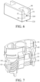
FIG. 7 is a schematic diagram of a porous body and flexible silicone sleeve inFIG. 5 that are assembled in a support frame; -
FIG. 8 is a schematic diagram in which a block portion opens an air pressure balance hole or channel after bending inFIG. 7 ; and -
FIG. 9 is a schematic structural diagram of a flexible silicone sleeve according to another embodiment. - For ease of understanding of this application, this application is described in more detail below with reference to the accompanying drawings and specific implementations.
- An embodiment of this application provides an electronic atomization device. Referring to
FIG. 1 , the electronic atomization device includes: anatomizer 100, configured to store a liquid substrate and atomize the liquid substrate to generate an aerosol; and apower supply assembly 200, configured to supply power to theatomizer 100. - In an optional implementation, as shown in
FIG. 1 , thepower supply assembly 200 includes: areceiving cavity 270, provided at an end in a length direction and configured to receive and accommodate at least a part of theatomizer 100; and a firstelectrical contact 230, at least partially exposed on a surface of thereceiving cavity 270, and configured to be electrically connected to theatomizer 100 when at least a part of theatomizer 100 is received and accommodated in thepower supply assembly 200, to supply power to theatomizer 100. - According to a preferred implementation shown in
FIG. 1 , a secondelectrical contact 21 is arranged on an end portion of theatomizer 100 opposite to thepower supply assembly 200 in the length direction, so that when at least a part of theatomizer 100 is received in thereceiving cavity 270, the secondelectrical contact 21 contacts with and abuts against the firstelectrical contact 230 to form conductivity. - A
seal member 260 is arranged inside thepower supply assembly 200, and at least a part of an inner space of thepower supply assembly 200 is separated through theseal member 260 to form thereceiving cavity 270. In the preferred implementation shown inFIG. 1 , theseal member 260 is configured to extend in a cross section direction of thepower supply assembly 200, and is prepared by a flexible material, so as to prevent the liquid substrate seeping from theatomizer 100 to thereceiving cavity 270 from flowing to acontroller 220, asensor 250, and other components inside thepower supply assembly 200. - In the preferred implementation shown in
FIG. 1 , thepower supply assembly 200 further includes: abattery cell 210, located at an other end facing away from thereceiving cavity 270 in the length direction, and configured to supply power; and acontroller 220, arranged between thebattery cell 210 and an accommodating cavity, and operably guiding a current between thebattery cell 210 and the firstelectrical contact 230. - During use, the
power supply assembly 200 includes asensor 250, configured to sense an inhalation airflow generated by asuction nozzle cap 20 of theatomizer 100 during inhalation, so that thecontroller 220 controls, according to a detection signal of thesensor 250, thebattery cell 210 to output the current to theatomizer 100. - Further, in the preferred implementation shown in
FIG. 1 , acharging interface 240 is arranged on an other end of thepower supply assembly 200 opposite to thereceiving cavity 270, and is configured to be connected to an external device charging device to charge thebattery cell 210. - Embodiments in
FIG. 2 to FIG. 4 are schematic structural diagrams of an embodiment of theatomizer 100 inFIG. 1 . Theatomizer 100 includes:
amain housing 10. As shown inFIG. 2 andFIG. 3 , themain housing 10 is substantially in a flat cylindrical shape, and certainly, a hollow interior of themain housing 10 is a necessary functional device configured to store and atomize the liquid substrate. Themain housing 10 has anear end 110 and a farend 120 opposite to each other in the length direction. According to requirements for common use, thenear end 110 is configured as an end for a user to inhale the aerosol, and a suction nozzle A for the user to inhale is arranged at thenear end 110; and thefar end 120 is used as an end combined with thepower supply assembly 200, and thefar end 120 of themain housing 10 is an opening on which adetachable end cap 20 is mounted. The opening is configured to mount necessary functional components inside themain housing 10. - Further, in the embodiment shown in
FIG. 2 , the secondelectrical contact 21 for conducting with the firstelectrical contact 230 of thepower supply assembly 200 is arranged on theend cap 20. - Further, referring to
FIG. 3 andFIG. 4 , aliquid storage cavity 12 configured to store a liquid substrate, aporous body 30 configured to absorb the liquid substrate from theliquid storage cavity 12, and aheating element 40 configured to heat and atomize the liquid substrate absorbed by theporous body 30 are arranged inside themain housing 10. Specifically, in a cross-sectional structural diagram shown inFIG. 4 , a vapor-gas transmission pipe 11 in an axial direction is arranged inside themain housing 10, and theliquid storage cavity 12 configured to store the liquid substrate is formed in a space between an outer wall of the vapor-gas transmission pipe 11 and an inner wall of themain housing 10. A first end of the vapor-gas transmission pipe 11 opposite to thenear end 110 is in communication with the suction nozzle A, and a second end opposite to thefar end 120 is in airflow connection with anatomization cavity 80 that releases the aerosol, thereby transmitting the aerosol generated by atomizing the liquid substrate by theheating element 40 and released to theatomization cavity 80 to the suction nozzle A for inhalation. - Referring to a structure of the
porous body 30 shown inFIG. 3 ,FIG. 4 , andFIG. 6 , a shape of theporous body 30 is configured to be substantially, but not limited to, a block structure in this embodiment. According to a preferred design in this embodiment, the porous body includes aliquid absorbing surface 310 and anatomization surface 320 that are arched in shape and face away from each other in the axial direction of themain housing 10, that is, an upper surface and a lower surface of a base portion of theporous body 30 inFIG. 3 . Theliquid absorbing surface 310 is opposite to theliquid storage cavity 12, and directly or indirectly contacts with the liquid substrate in theliquid storage cavity 12 to absorb the liquid substrate. A microporous structure inside theporous body 30 conducts the liquid substrate to theatomization surface 320 for heating and atomizing to form the aerosol, and the aerosol is released or escapes from theatomization surface 320. For the structure of theporous body 30 shown inFIG. 4 , because theliquid absorbing surface 310 is parallel to theatomization surface 320, both movement directions of the liquid substrate and the aerosol in theporous body 30 are perpendicular to a plane on which theatomization surface 320 is located. The aerosol and the liquid substrate move in theporous body 30 more smoothly and are relatively convenient to manufacture. - Further, referring to
FIG. 6 , theporous body 30 is arched in shape and has afirst side wall 31 and asecond side wall 32 opposite to each other in a thickness direction, and abase part 34 extending between thefirst side wall 31 and thesecond side wall 32. An upper surface and a lower surface of thebase part 34 are respectively configured as theliquid absorbing surface 310 and theatomization surface 320. In addition, thefirst side wall 31 and thesecond side wall 32 extend in a width direction to define aliquid channel 33 between thefirst side wall 31 and thesecond side wall 32, and theliquid absorbing surface 310 is exposed in theliquid channel 33 to absorb the liquid substrate. - In some implementations, the
porous body 30 may be made of a material of a hard capillary structure such as a porous ceramic, a porous glass ceramic, or a porous glass. Theheating element 40 is preferably formed on theatomization surface 320 by mixing conductive raw material powder with a printing assistant to form a slurry and then sintering after printing, so that an entire surface or most of the surface of the heating element is closely attached to theatomization surface 320, and the heating element has effects such as high atomization efficiency, less heat loss, and dry-burn prevention or dry-bum reduction. In some embodiments, theheating element 40 may be made of a material such as stainless steel, nickel chromium alloy, iron chromium aluminum alloy, or metal titanium. - Further, referring to
FIG. 3 andFIG. 4 , to assist in mounting and fixing theporous body 30 and sealing theliquid storage cavity 12, themain housing 10 is further provided with aflexible seal element 50, arigid support frame 60, and aflexible seal element 70. Theflexible seal element 50 can not only seal an opening of theliquid storage cavity 12, but also fixes and holds theporous body 30 inside thesupport frame 60. For a specific structure and shape, theflexible seal element 50 may be a flexible silicone sleeve, and the flexible silicone sleeve is substantially in a hollow cylinder shape. A hollow interior is configured to accommodate theporous body 30, and is sleeved outside theporous body 30 in a tight fitting manner. - The
rigid support frame 60 holds theporous body 30 sleeved with theflexible silicone sleeve 50. In some embodiments, the rigid support frame may be substantially in a ring shape with a lower end being an opening, and an inner space thereof is configured to accommodate and hold theflexible silicone sleeve 50 and theporous body 30. On one hand, theflexible silicone sleeve 50 can seal a gap between theporous body 30 and thesupport frame 60 to prevent the liquid substrate from seeping out of the gap between theporous body 30 and thesupport frame 60. On the other hand, theflexible silicone sleeve 50 is located between theporous body 30 and thesupport frame 60, which is advantageous for theporous body 30 to be stably accommodated in thesupport frame 60 to avoid loosening. - The
flexible seal element 70 is arranged on an end portion of theliquid storage cavity 12 facing thefar end 120, and a shape thereof matches a cross section of an inner contour of themain housing 10, thereby sealing theliquid storage cavity 12 and preventing the liquid substrate from seeping from theliquid storage cavity 12. Further, to prevent shrinkage and deformation of aflexible silicone base 53 made of a flexible material from affecting sealing tightness, therigid support frame 60 is accommodated in theflexible seal element 70 to support the flexible silicone base. - After mounting, to ensure smooth conveying of the liquid substrate and output of the aerosol, a first
liquid guide hole 71 for the liquid substrate to flow through is provided on theflexible seal element 70, a secondliquid guide hole 61 is correspondingly provided on therigid support frame 60, and a thirdliquid guide hole 51 is provided on theflexible silicone sleeve 50. During use, the liquid substrate in theliquid storage cavity 12 sequentially passes through the firstliquid guide hole 71, the secondliquid guide hole 61, and the thirdliquid guide hole 51 and flows to theliquid channel 33 of theporous body 30 held in theflexible silicone sleeve 50, and then is absorbed by theliquid absorbing surface 310. Further, as shown by arrow R1 inFIG. 4 , the liquid substrate is absorbed and conveyed to theatomization surface 320 for atomization, and then the generated aerosol is released into theatomization cavity 80 defined between theatomization surface 320 and theend cap 20. - During inhalation, for an output structure of the aerosol, referring to
FIG. 3 to FIG. 6 , afirst insertion hole 72 for a lower end of the vapor-gas transmission pipe 11 to insert is provided on theflexible seal element 70, asecond insertion hole 62 is correspondingly provided on therigid support frame 60, and afirst airflow channel 65 for theatomization surface 320 and thesecond insertion hole 62 to be in airflow communication is provided on one side of therigid support frame 60 opposite to themain housing 10. After mounting, a complete airflow inhalation path is shown by arrow R2 inFIG. 3 . The external air enters theatomization cavity 80 through anair inlet 23 on theend cap 20, carries the generated aerosol to flow from thefirst airflow channel 65 to thesecond insertion hole 62, and then is outputted to the vapor-gas transmission pipe 11 through thefirst insertion hole 72. - In the preferred embodiments shown in
FIG. 3 andFIG. 4 , theend cap 20 is further provided with a circumferential seal ring 25 surrounding theend cap 20. The seal ring is configured to seal a gap between themain housing 10 and theend cap 20. - With reference to the shape of the
porous body 30 shown inFIG. 6 ,FIG. 3 andFIG. 4 show the structure of thesupport frame 60 that can supplement air into theliquid storage cavity 12 through theliquid channel 33 of theporous body 30. Specifically, each of two opposite side walls of thesupport frame 60 in a width direction thereof is provided with an airpressure balance channel 64. The airpressure balance channel 64 provides an air channel for air to enter theliquid channel 33, and the air channel may be formed by pores running through the side walls. The airpressure balance channel 64 is configured to extend in the length direction of placing the porous body and is opposite to theliquid channel 33 of theporous body 30, that is, the airpressure balance channel 64 extends substantially in a same direction as theliquid channel 33. - In a specific implementation, with reference to examples shown in
FIG. 3 andFIG. 4 , a holding space 66 for accommodating and holding theporous body 30 is provided in thesupport frame 60. The airpressure balance channel 64 runs through from an inner wall surface of the holding space 66 to an outer wall surface of thesupport frame 60, and the airpressure balance channel 64 includes an air inlet end and an air outlet end. The air inlet end is located on the outer wall surface of thesupport frame 60, and the air outlet end is located on the inner wall surface of the holding space 66, so that when the porous body is accommodated in the holding space 66, the air outlet end of the airpressure balance channel 64 is close to theliquid channel 33. In the example shown inFIG. 4 , the airpressure balance channel 64 is configured to face theliquid channel 33. - In addition, to prevent the air
pressure balance channel 64 from directly communicating with theliquid channel 33 of theporous body 30, causing the conveyed liquid substrate to be leaked out from the airpressure balance channel 64, ablock portion 53 extending in the length direction of themain housing 10 is arranged on an end portion of theflexible silicone sleeve 50 in the width direction shown inFIG. 5 includes. When theflexible silicone sleeve 50 wraps theporous body 30 and then is accommodated in thesupport frame 60, theblock portion 53 may block or seal the airpressure balance channel 64, as shown inFIG. 7 . - As the liquid substrate in the
liquid storage cavity 12 is gradually consumed, a negative pressure in theliquid storage cavity 12 gradually increases. When the negative pressure exceeds a certain threshold, theblock portion 53 bends or deforms in a direction away from the airpressure balance channel 64, thereby opening the airpressure balance channel 64. As shown inFIG. 8 , in this case, the external air can enter the secondliquid guide hole 61 through the airpressure balance channel 64 and finally enter theliquid storage cavity 12, at least partially eliminating or relieving the negative pressure in theliquid storage cavity 12, and maintaining smooth supply of the liquid substrate to theporous body 30. - In other feasible implementations, a specific form of the air channel provided on the
support frame 60 may be diversified. For example, the air channel includes a groove provided on the inner wall surface of the holding space 66. An end of the groove extends outside the holding space 66 to facilitate air to enter the groove, and an other end of the groove terminates at a position on the inner wall surface of the holding space 66, and the position is close to the liquid channel on the porous body. The groove may be partially covered by theflexible silicone sleeve 50, a termination end of the groove is configured as the air outlet end of the air channel, and the termination end is covered by theblock portion 53 on theflexible silicone sleeve 50, so that an air pressure of the groove can push theblock portion 53 to deform toward the liquid channel, thereby causing the termination end of the groove to be in fluid communication with the liquid channel. - In the preferred embodiment shown in
FIG. 5 , theblock portion 53 is suspended in a form of a cantilever. Further, inFIG. 5 , a recessedstructure 531 is further arranged on theblock portion 53. The recessedstructure 531 reduces the thickness or strength of theblock portion 53, so that the block portion is easier to bend or deform under a negative pressure. -
FIG. 9 shows a schematic structural diagram of aflexible silicone sleeve 50a according to another variation embodiment. A portion of theflexible silicone sleeve 50a corresponding to an end opening of the airpressure balance channel 64 is recessed inward to form ablock portion 53a that blocks or seals the airpressure balance channel 64. In addition, a notch or aslit 531a is formed on theblock portion 53a, and when the negative pressure in theliquid storage cavity 12 increases beyond a threshold range, theblock portion 53a is further recessed and deformed inward to further open or enlarge the notch or slit 531a, thereby opening the end opening of the airpressure balance channel 64 to allow the external air to enter. - Further, in a preferred embodiment, the notch or the
slit 531a is in a shape of a cross. - The notch or the
slit 531a inFIG. 9 may be formed in mold molding, or may be formed in manners such as cutting and carving. In a non-inhalation state, theblock portion 53a closes the notch or theslit 531a by a pressure of the liquid substrate in theliquid channel 33. During inhalation, the negative pressure in theliquid storage cavity 12 gradually increases and is conveyed to theliquid channel 33, and the notch or theslit 531a can be enlarged and opened, thereby opening the end opening of the airpressure balance channel 64 to allow the external air to enter. - Further, as shown in
FIG. 7 andFIG. 8 , after assembly, the airpressure balance channel 64 is in airflow communication with theatomization cavity 80 through a gap between thesupport frame 60 and themain housing 10, or the like. Therefore, during implementations, when theblock portion 53 is bent or deformed to open the airpressure balance channel 64, the air in theatomization cavity 80 enters theliquid storage cavity 12 through the airpressure balance channel 64 to relieve the negative pressure. In a preferred embodiment, a plurality ofcapillary grooves 65 extending in a circumferential direction are arranged on an outer surface of thesupport frame 60. Thecapillary grooves 65 can, on one hand, provide a path for airflow communication between the airpressure balance channel 64 and theatomization cavity 80, and on the other hand, maintain aerosol condensate in theatomization cavity 80 or in the airflow in a manner of capillary adsorption. - It should be noted that, the specification of this application and the accompanying drawings thereof illustrate preferred embodiments of this application, but this application is not limited to the embodiments described in this specification. Further, a person of ordinary skill in the art may make improvements or modifications according to the foregoing description, and all the improvements and modifications shall fall within the protection scope of the attached claims of this application.
Claims (11)
- An atomizer, comprising:a liquid storage cavity, configured to store a liquid substrate;a porous body, comprising a liquid channel running through the porous body in a length direction and being in fluid communication with the liquid storage cavity through the liquid channel to absorb the liquid substrate of the liquid storage cavity;a heating element, combined with the porous body and configured to heat at least a part of the liquid substrate in the porous body to generate an aerosol;a support frame, configured to hold the porous body, wherein at least one air channel is provided on the support frame, and the air channel comprises an air inlet end and an air outlet end close to the liquid channel; anda flexible seal element, positioned between the support frame and the porous body, wherein the seal element comprises a block portion that blocks or seals the air outlet end, and the block portion is configured to bend or deform in response to a negative pressure change in the liquid storage cavity to open the air channel for air to enter the liquid channel.
- The atomizer according to claim 1, wherein the support frame comprises a holding cavity, and the porous body is accommodated and held in the holding cavity; and
the at least one air channel extends from an inner surface of the holding cavity to an outer surface of the support frame. - The atomizer according to claim 1 or 2, wherein the block portion is configured to be located between the liquid channel and the air channel.
- The atomizer according to claim 1 or 2, wherein the at least one air channel is configured to extend in the length direction of the porous body.
- The atomizer according to claim 1 or 2, wherein the block portion is suspended relative to other parts of the seal element.
- The atomizer according to claim 1 or 2, wherein a notch or a slit is provided on the block portion; and the notch or the slit is configured to open or enlarge in response to the negative pressure change in the liquid storage cavity, thereby opening the air channel.
- The atomizer according to claim 1 or 2, wherein a recessed structure is arranged on the block portion to reduce strength of the block portion, so that the block portion is easier to bend or deform.
- The atomizer according to claim 1 or 2, wherein the porous body comprises a liquid absorbing surface adjacent to the liquid channel for absorbing the liquid substrate, and an atomization surface for the aerosol to release and escape; and
the atomizer comprises an atomization cavity that is in airflow communication with external air, wherein at least a part of the atomization cavity is defined by the atomization surface, and the air channel is in airflow communication with the atomization cavity and then is in communication with the external air. - The atomizer according to claim 2, wherein the seal element is configured in the holding cavity and wraps at least a part of an outer surface of the porous body.
- The atomizer according to claim 1 or 2, wherein the air outlet end of the air channel is configured to face the liquid channel.
- An electronic atomization device, comprising an atomizer for atomizing a liquid substrate to generate an aerosol, and a power supply assembly for supplying power to the atomizer, wherein the atomizer comprises the atomizer according to any one of claims 1 to 10.
Applications Claiming Priority (2)
| Application Number | Priority Date | Filing Date | Title |
|---|---|---|---|
| CN202022360789.5U CN213819836U (en) | 2020-10-21 | 2020-10-21 | Atomizers and Electronic Atomizers |
| PCT/CN2021/125372 WO2022083697A1 (en) | 2020-10-21 | 2021-10-21 | Atomizer and electronic atomization device |
Publications (3)
| Publication Number | Publication Date |
|---|---|
| EP4233582A1 true EP4233582A1 (en) | 2023-08-30 |
| EP4233582A4 EP4233582A4 (en) | 2024-04-03 |
| EP4233582B1 EP4233582B1 (en) | 2025-09-17 |
Family
ID=77010605
Family Applications (1)
| Application Number | Title | Priority Date | Filing Date |
|---|---|---|---|
| EP21882112.2A Active EP4233582B1 (en) | 2020-10-21 | 2021-10-21 | Atomizer and electronic atomization device |
Country Status (4)
| Country | Link |
|---|---|
| US (1) | US20230389615A1 (en) |
| EP (1) | EP4233582B1 (en) |
| CN (1) | CN213819836U (en) |
| WO (1) | WO2022083697A1 (en) |
Cited By (2)
| Publication number | Priority date | Publication date | Assignee | Title |
|---|---|---|---|---|
| EP4166014A4 (en) * | 2020-06-16 | 2023-12-06 | Shenzhen First Union Technology Co., Ltd. | Atomizer, electronic atomization device, and sealing element for atomizer |
| EP4529783A1 (en) * | 2023-09-29 | 2025-04-02 | JT International SA | Aerosol generating systems and cartridges for use in aerosol generating systems |
Families Citing this family (8)
| Publication number | Priority date | Publication date | Assignee | Title |
|---|---|---|---|---|
| CN213819836U (en) * | 2020-10-21 | 2021-07-30 | 深圳市合元科技有限公司 | Atomizers and Electronic Atomizers |
| DE102021123746A1 (en) | 2021-09-14 | 2023-03-16 | Körber Technologies Gmbh | Cartridge element, evaporator cartridge and evaporator system with pressure compensation element and method for production |
| CN115989901A (en) * | 2021-10-19 | 2023-04-21 | 比亚迪精密制造有限公司 | An electronic cigarette device and electronic cigarette |
| WO2023115481A1 (en) * | 2021-12-23 | 2023-06-29 | 深圳市华诚达精密工业有限公司 | Atomization device having good atomization effect |
| CN116616499A (en) * | 2022-02-14 | 2023-08-22 | 深圳市合元科技有限公司 | Atomizer, electronic atomization device and sealing element for electronic atomization device |
| CN117694623A (en) * | 2022-09-06 | 2024-03-15 | 深圳市新宜康科技股份有限公司 | Atomizing core, atomizer and electronic atomizing device |
| CN117770514A (en) * | 2022-09-29 | 2024-03-29 | 上海琨纬科技有限公司 | Atomizing core support and atomizer |
| EP4467024A1 (en) * | 2023-05-23 | 2024-11-27 | JT International SA | Aerosal generating systems and cartridges for use in aerosol generating systems |
Family Cites Families (8)
| Publication number | Priority date | Publication date | Assignee | Title |
|---|---|---|---|---|
| US20140318557A1 (en) * | 2013-04-25 | 2014-10-30 | Elijah Bremer | Smoking or vaporizing device |
| CN207653589U (en) * | 2017-11-02 | 2018-07-27 | 常州市派腾电子技术服务有限公司 | Electronic cigarette and its atomizer |
| CN209498584U (en) * | 2018-12-26 | 2019-10-18 | 深圳市合元科技有限公司 | Vape atomizer and electronic cigarette |
| CN110250577B (en) * | 2019-06-17 | 2022-08-16 | 深圳麦克韦尔科技有限公司 | Electronic atomization device and atomizer thereof |
| CN110313647A (en) * | 2019-07-30 | 2019-10-11 | 深圳雾芯科技有限公司 | A kind of atomising device |
| CN110613166B (en) * | 2019-09-04 | 2025-03-18 | 深圳麦克韦尔科技有限公司 | Electronic atomization device and atomization component thereof, cigarette bomb tube |
| CN111657548A (en) * | 2020-05-15 | 2020-09-15 | 深圳麦克韦尔科技有限公司 | Electronic atomization device and atomizer thereof |
| CN213819836U (en) * | 2020-10-21 | 2021-07-30 | 深圳市合元科技有限公司 | Atomizers and Electronic Atomizers |
-
2020
- 2020-10-21 CN CN202022360789.5U patent/CN213819836U/en active Active
-
2021
- 2021-10-21 US US18/033,304 patent/US20230389615A1/en active Pending
- 2021-10-21 EP EP21882112.2A patent/EP4233582B1/en active Active
- 2021-10-21 WO PCT/CN2021/125372 patent/WO2022083697A1/en not_active Ceased
Cited By (2)
| Publication number | Priority date | Publication date | Assignee | Title |
|---|---|---|---|---|
| EP4166014A4 (en) * | 2020-06-16 | 2023-12-06 | Shenzhen First Union Technology Co., Ltd. | Atomizer, electronic atomization device, and sealing element for atomizer |
| EP4529783A1 (en) * | 2023-09-29 | 2025-04-02 | JT International SA | Aerosol generating systems and cartridges for use in aerosol generating systems |
Also Published As
| Publication number | Publication date |
|---|---|
| CN213819836U (en) | 2021-07-30 |
| US20230389615A1 (en) | 2023-12-07 |
| EP4233582A4 (en) | 2024-04-03 |
| EP4233582B1 (en) | 2025-09-17 |
| WO2022083697A1 (en) | 2022-04-28 |
Similar Documents
| Publication | Publication Date | Title |
|---|---|---|
| EP4233582B1 (en) | Atomizer and electronic atomization device | |
| EP4305977A1 (en) | Atomizer and electronic atomizing device | |
| EP3888476B1 (en) | Atomizing core, atomizer and electronic atomizing device | |
| EP4166023A1 (en) | Electronic cigarette atomiser and electronic cigarette | |
| CN213587425U (en) | Electronic Cigarettes and Electronic Cigarettes | |
| US20250098773A1 (en) | Vaporizer and electronic vaporization device | |
| CN214431782U (en) | Atomizer and electronic atomization device | |
| EP4252562A1 (en) | Atomiser and electronic atomising apparatus | |
| CN115590254B (en) | Atomizing components, atomizers and aerosol generating devices | |
| CN216315620U (en) | Heating assembly, atomizer and electronic atomization device | |
| CN215958369U (en) | Atomizer and aerosol-generating device | |
| CN218737203U (en) | Atomizer and electronic atomization device | |
| EP4289295A1 (en) | Atomizer and electronic atomization device | |
| EP4381970A1 (en) | Atomizer and electronic atomization device | |
| CN215684857U (en) | Atomizer and electronic atomization device | |
| CN219982148U (en) | Atomizer and electronic atomization device | |
| EP4285747A1 (en) | Atomizer and electronic atomization device | |
| CN222171328U (en) | Electronic atomizing device | |
| CN218354596U (en) | Electronic atomization device and atomizer | |
| CN115462560A (en) | Atomizers and Electronic Atomization Devices | |
| CN220274915U (en) | Atomizers and electronic atomization devices | |
| CN216059195U (en) | Electronic atomizer | |
| EP4487704A1 (en) | Atomizer and electronic atomization device | |
| CN224192928U (en) | Electronic atomizing device | |
| CN220458619U (en) | Atomizer and electronic atomization device comprising same |
Legal Events
| Date | Code | Title | Description |
|---|---|---|---|
| STAA | Information on the status of an ep patent application or granted ep patent |
Free format text: STATUS: THE INTERNATIONAL PUBLICATION HAS BEEN MADE |
|
| PUAI | Public reference made under article 153(3) epc to a published international application that has entered the european phase |
Free format text: ORIGINAL CODE: 0009012 |
|
| STAA | Information on the status of an ep patent application or granted ep patent |
Free format text: STATUS: REQUEST FOR EXAMINATION WAS MADE |
|
| 17P | Request for examination filed |
Effective date: 20230510 |
|
| AK | Designated contracting states |
Kind code of ref document: A1 Designated state(s): AL AT BE BG CH CY CZ DE DK EE ES FI FR GB GR HR HU IE IS IT LI LT LU LV MC MK MT NL NO PL PT RO RS SE SI SK SM TR |
|
| DAV | Request for validation of the european patent (deleted) | ||
| DAX | Request for extension of the european patent (deleted) | ||
| REG | Reference to a national code |
Ref country code: DE Ref legal event code: R079 Free format text: PREVIOUS MAIN CLASS: A24F0040100000 Ipc: A24F0040400000 Ref country code: DE Ref legal event code: R079 Ref document number: 602021038935 Country of ref document: DE Free format text: PREVIOUS MAIN CLASS: A24F0040100000 Ipc: A24F0040400000 |
|
| STAA | Information on the status of an ep patent application or granted ep patent |
Free format text: STATUS: EXAMINATION IS IN PROGRESS |
|
| A4 | Supplementary search report drawn up and despatched |
Effective date: 20240305 |
|
| RIC1 | Information provided on ipc code assigned before grant |
Ipc: A24F 40/485 20200101ALI20240228BHEP Ipc: A24F 40/40 20200101AFI20240228BHEP |
|
| 17Q | First examination report despatched |
Effective date: 20240315 |
|
| GRAP | Despatch of communication of intention to grant a patent |
Free format text: ORIGINAL CODE: EPIDOSNIGR1 |
|
| STAA | Information on the status of an ep patent application or granted ep patent |
Free format text: STATUS: GRANT OF PATENT IS INTENDED |
|
| INTG | Intention to grant announced |
Effective date: 20250520 |
|
| GRAS | Grant fee paid |
Free format text: ORIGINAL CODE: EPIDOSNIGR3 |
|
| GRAA | (expected) grant |
Free format text: ORIGINAL CODE: 0009210 |
|
| STAA | Information on the status of an ep patent application or granted ep patent |
Free format text: STATUS: THE PATENT HAS BEEN GRANTED |
|
| AK | Designated contracting states |
Kind code of ref document: B1 Designated state(s): AL AT BE BG CH CY CZ DE DK EE ES FI FR GB GR HR HU IE IS IT LI LT LU LV MC MK MT NL NO PL PT RO RS SE SI SK SM TR |
|
| REG | Reference to a national code |
Ref country code: GB Ref legal event code: FG4D |
|
| REG | Reference to a national code |
Ref country code: CH Ref legal event code: EP |
|
| REG | Reference to a national code |
Ref country code: IE Ref legal event code: FG4D |
|
| REG | Reference to a national code |
Ref country code: DE Ref legal event code: R096 Ref document number: 602021038935 Country of ref document: DE |
|
| PGFP | Annual fee paid to national office [announced via postgrant information from national office to epo] |
Ref country code: GB Payment date: 20251023 Year of fee payment: 5 |
|
| PG25 | Lapsed in a contracting state [announced via postgrant information from national office to epo] |
Ref country code: NO Free format text: LAPSE BECAUSE OF FAILURE TO SUBMIT A TRANSLATION OF THE DESCRIPTION OR TO PAY THE FEE WITHIN THE PRESCRIBED TIME-LIMIT Effective date: 20251217 |
|
| REG | Reference to a national code |
Ref country code: LT Ref legal event code: MG9D |
|
| PGFP | Annual fee paid to national office [announced via postgrant information from national office to epo] |
Ref country code: AT Payment date: 20260113 Year of fee payment: 5 |
|
| PG25 | Lapsed in a contracting state [announced via postgrant information from national office to epo] |
Ref country code: FI Free format text: LAPSE BECAUSE OF FAILURE TO SUBMIT A TRANSLATION OF THE DESCRIPTION OR TO PAY THE FEE WITHIN THE PRESCRIBED TIME-LIMIT Effective date: 20250917 |
|
| PG25 | Lapsed in a contracting state [announced via postgrant information from national office to epo] |
Ref country code: HR Free format text: LAPSE BECAUSE OF FAILURE TO SUBMIT A TRANSLATION OF THE DESCRIPTION OR TO PAY THE FEE WITHIN THE PRESCRIBED TIME-LIMIT Effective date: 20250917 |
|
| PGFP | Annual fee paid to national office [announced via postgrant information from national office to epo] |
Ref country code: FR Payment date: 20251027 Year of fee payment: 5 |
|
| PG25 | Lapsed in a contracting state [announced via postgrant information from national office to epo] |
Ref country code: GR Free format text: LAPSE BECAUSE OF FAILURE TO SUBMIT A TRANSLATION OF THE DESCRIPTION OR TO PAY THE FEE WITHIN THE PRESCRIBED TIME-LIMIT Effective date: 20251218 |
|
| PG25 | Lapsed in a contracting state [announced via postgrant information from national office to epo] |
Ref country code: SE Free format text: LAPSE BECAUSE OF FAILURE TO SUBMIT A TRANSLATION OF THE DESCRIPTION OR TO PAY THE FEE WITHIN THE PRESCRIBED TIME-LIMIT Effective date: 20250917 |
|
| REG | Reference to a national code |
Ref country code: NL Ref legal event code: MP Effective date: 20250917 |
|
| PG25 | Lapsed in a contracting state [announced via postgrant information from national office to epo] |
Ref country code: LV Free format text: LAPSE BECAUSE OF FAILURE TO SUBMIT A TRANSLATION OF THE DESCRIPTION OR TO PAY THE FEE WITHIN THE PRESCRIBED TIME-LIMIT Effective date: 20250917 |
|
| PG25 | Lapsed in a contracting state [announced via postgrant information from national office to epo] |
Ref country code: BG Free format text: LAPSE BECAUSE OF FAILURE TO SUBMIT A TRANSLATION OF THE DESCRIPTION OR TO PAY THE FEE WITHIN THE PRESCRIBED TIME-LIMIT Effective date: 20250917 |
|
| PG25 | Lapsed in a contracting state [announced via postgrant information from national office to epo] |
Ref country code: RS Free format text: LAPSE BECAUSE OF FAILURE TO SUBMIT A TRANSLATION OF THE DESCRIPTION OR TO PAY THE FEE WITHIN THE PRESCRIBED TIME-LIMIT Effective date: 20251217 |
|
| PG25 | Lapsed in a contracting state [announced via postgrant information from national office to epo] |
Ref country code: NL Free format text: LAPSE BECAUSE OF FAILURE TO SUBMIT A TRANSLATION OF THE DESCRIPTION OR TO PAY THE FEE WITHIN THE PRESCRIBED TIME-LIMIT Effective date: 20250917 |
|
| REG | Reference to a national code |
Ref country code: AT Ref legal event code: MK05 Ref document number: 1837474 Country of ref document: AT Kind code of ref document: T Effective date: 20250917 |
|
| PG25 | Lapsed in a contracting state [announced via postgrant information from national office to epo] |
Ref country code: SM Free format text: LAPSE BECAUSE OF FAILURE TO SUBMIT A TRANSLATION OF THE DESCRIPTION OR TO PAY THE FEE WITHIN THE PRESCRIBED TIME-LIMIT Effective date: 20250917 |
|
| PG25 | Lapsed in a contracting state [announced via postgrant information from national office to epo] |
Ref country code: ES Free format text: LAPSE BECAUSE OF FAILURE TO SUBMIT A TRANSLATION OF THE DESCRIPTION OR TO PAY THE FEE WITHIN THE PRESCRIBED TIME-LIMIT Effective date: 20250917 |
|
| PGFP | Annual fee paid to national office [announced via postgrant information from national office to epo] |
Ref country code: DE Payment date: 20251223 Year of fee payment: 5 |
|
| PG25 | Lapsed in a contracting state [announced via postgrant information from national office to epo] |
Ref country code: AT Free format text: LAPSE BECAUSE OF FAILURE TO SUBMIT A TRANSLATION OF THE DESCRIPTION OR TO PAY THE FEE WITHIN THE PRESCRIBED TIME-LIMIT Effective date: 20250917 |
|
| PG25 | Lapsed in a contracting state [announced via postgrant information from national office to epo] |
Ref country code: IT Free format text: LAPSE BECAUSE OF FAILURE TO SUBMIT A TRANSLATION OF THE DESCRIPTION OR TO PAY THE FEE WITHIN THE PRESCRIBED TIME-LIMIT Effective date: 20250917 Ref country code: RO Free format text: LAPSE BECAUSE OF FAILURE TO SUBMIT A TRANSLATION OF THE DESCRIPTION OR TO PAY THE FEE WITHIN THE PRESCRIBED TIME-LIMIT Effective date: 20250917 |
|
| PG25 | Lapsed in a contracting state [announced via postgrant information from national office to epo] |
Ref country code: IS Free format text: LAPSE BECAUSE OF FAILURE TO SUBMIT A TRANSLATION OF THE DESCRIPTION OR TO PAY THE FEE WITHIN THE PRESCRIBED TIME-LIMIT Effective date: 20260117 |
|
| PG25 | Lapsed in a contracting state [announced via postgrant information from national office to epo] |
Ref country code: CZ Free format text: LAPSE BECAUSE OF FAILURE TO SUBMIT A TRANSLATION OF THE DESCRIPTION OR TO PAY THE FEE WITHIN THE PRESCRIBED TIME-LIMIT Effective date: 20250917 Ref country code: PT Free format text: LAPSE BECAUSE OF FAILURE TO SUBMIT A TRANSLATION OF THE DESCRIPTION OR TO PAY THE FEE WITHIN THE PRESCRIBED TIME-LIMIT Effective date: 20260119 |
|
| PG25 | Lapsed in a contracting state [announced via postgrant information from national office to epo] |
Ref country code: PL Free format text: LAPSE BECAUSE OF FAILURE TO SUBMIT A TRANSLATION OF THE DESCRIPTION OR TO PAY THE FEE WITHIN THE PRESCRIBED TIME-LIMIT Effective date: 20250917 |
|
| PG25 | Lapsed in a contracting state [announced via postgrant information from national office to epo] |
Ref country code: EE Free format text: LAPSE BECAUSE OF FAILURE TO SUBMIT A TRANSLATION OF THE DESCRIPTION OR TO PAY THE FEE WITHIN THE PRESCRIBED TIME-LIMIT Effective date: 20250917 Ref country code: SK Free format text: LAPSE BECAUSE OF FAILURE TO SUBMIT A TRANSLATION OF THE DESCRIPTION OR TO PAY THE FEE WITHIN THE PRESCRIBED TIME-LIMIT Effective date: 20250917 |