EP4233519A2 - Mowing unit with integrated cleaning system - Google Patents
Mowing unit with integrated cleaning system Download PDFInfo
- Publication number
- EP4233519A2 EP4233519A2 EP23167890.5A EP23167890A EP4233519A2 EP 4233519 A2 EP4233519 A2 EP 4233519A2 EP 23167890 A EP23167890 A EP 23167890A EP 4233519 A2 EP4233519 A2 EP 4233519A2
- Authority
- EP
- European Patent Office
- Prior art keywords
- water
- water feeding
- housing
- section
- feeding pipe
- Prior art date
- Legal status (The legal status is an assumption and is not a legal conclusion. Google has not performed a legal analysis and makes no representation as to the accuracy of the status listed.)
- Granted
Links
Images




Classifications
-
- A—HUMAN NECESSITIES
- A01—AGRICULTURE; FORESTRY; ANIMAL HUSBANDRY; HUNTING; TRAPPING; FISHING
- A01D—HARVESTING; MOWING
- A01D34/00—Mowers; Mowing apparatus of harvesters
- A01D34/001—Accessories not otherwise provided for
- A01D34/003—Means for cleaning the machine
-
- A—HUMAN NECESSITIES
- A01—AGRICULTURE; FORESTRY; ANIMAL HUSBANDRY; HUNTING; TRAPPING; FISHING
- A01D—HARVESTING; MOWING
- A01D34/00—Mowers; Mowing apparatus of harvesters
- A01D34/01—Mowers; Mowing apparatus of harvesters characterised by features relating to the type of cutting apparatus
- A01D34/412—Mowers; Mowing apparatus of harvesters characterised by features relating to the type of cutting apparatus having rotating cutters
- A01D34/63—Mowers; Mowing apparatus of harvesters characterised by features relating to the type of cutting apparatus having rotating cutters having cutters rotating about a vertical axis
- A01D34/64—Mowers; Mowing apparatus of harvesters characterised by features relating to the type of cutting apparatus having rotating cutters having cutters rotating about a vertical axis mounted on a vehicle, e.g. a tractor, or drawn by an animal or a vehicle
- A01D34/66—Mowers; Mowing apparatus of harvesters characterised by features relating to the type of cutting apparatus having rotating cutters having cutters rotating about a vertical axis mounted on a vehicle, e.g. a tractor, or drawn by an animal or a vehicle with two or more cutters
-
- A—HUMAN NECESSITIES
- A01—AGRICULTURE; FORESTRY; ANIMAL HUSBANDRY; HUNTING; TRAPPING; FISHING
- A01D—HARVESTING; MOWING
- A01D2101/00—Lawn-mowers
-
- A—HUMAN NECESSITIES
- A01—AGRICULTURE; FORESTRY; ANIMAL HUSBANDRY; HUNTING; TRAPPING; FISHING
- A01D—HARVESTING; MOWING
- A01D34/00—Mowers; Mowing apparatus of harvesters
- A01D34/01—Mowers; Mowing apparatus of harvesters characterised by features relating to the type of cutting apparatus
- A01D34/02—Mowers; Mowing apparatus of harvesters characterised by features relating to the type of cutting apparatus having reciprocating cutters
- A01D34/03—Mowers; Mowing apparatus of harvesters characterised by features relating to the type of cutting apparatus having reciprocating cutters mounted on a vehicle, e.g. a tractor, or drawn by an animal or a vehicle
- A01D34/06—Mowers; Mowing apparatus of harvesters characterised by features relating to the type of cutting apparatus having reciprocating cutters mounted on a vehicle, e.g. a tractor, or drawn by an animal or a vehicle with cutters at the side
Definitions
- the present invention relates to a mower unit having a plurality of blades which are disposed inside a housing and rotatably driven about vertical axes.
- This type of mower unit is provided with a water discharging section for discharging cleaning water supplied to a water feeding section towards the blades (see e.g. Patent Document 1 " Japanese Patent Application No. 2011-205946 ").
- the object of the present invention is to provide a mower unit that allows a cleaning operation to proceed in an efficient manner.
- a mower unit according to the present invention comprises:
- the water discharging section discharges cleaning water toward the inner wall face of the housing.
- the water discharging section discharges the cleaning water to the inner wall face of the housing, it becomes possible to clean with emphasis the inner wall face where cut grass pieces or like can be easily accumulated, e.g. the inner wall faces of corner portions between the ceiling wall and the side wall inside the housing. Further the cleaning water discharged toward the inner wall face will be splashed back from the inner wall face to hit the blade, whereby the cleaning water will be stirred inside the housing. Therefore, while the portion of the inner wall face of the housing where the cut grass pieces or the like can be easily accumulated is cleaned with emphasis, the entire inner wall of the housing can be cleaned, so the cleaning operation can proceed in an efficient manner.
- the water discharging section is provided in the space formed between the vertical wall portion and the rear wall portion, adherence of cut grass pieces or the like to the water discharging section can be suppressed and it is also possible to suppress occurrence of collision of small stones or the like bounced off by the blade against the water discharging section to damage this water discharging section.
- branch water feeding pipes are connected to and branch from the main water feeding pipe, whereby the cleaning water can be fed from one water feeding section to a plurality of water discharging section.
- the branch water feeding pipe is disposed in the space between the vertical wall portion and the rear wall portion, it is possible to suppress occurrence of collision of small stones or the like bounced off by the rotatably driven blade against the branch water feeding pipe to damage this branch water feeding pipe.
- the water discharging section discharges water toward a ceiling face of the inner wall face.
- the cleaning water discharged against the ceiling face of the housing will drop onto the blade or the cleaning water will flow on/along the side wall portion or the front and rear wall portions of the housing.
- the water discharging section discharges water toward at least a portion of the inner wall face overlapped with the rotational trajectory of the blade as seen in a plan view.
- the cleaning water discharged against the ceiling face will drop onto the blade.
- the blade will be cleaned by the cleaning water dropped onto the blade.
- the cleaning water will be stirred by the rotatably driven blade, so that the inside of the housing can be cleaned.
- the cleaning water fed from the water feeding section will flow through the main water feeding pipe and will be fed from the main water feeding pipe via the branch connecting portion to the branch water feeding pipe.
- the branch connecting portion is provided under an inclined state inclined on the downstream side of the water flowing direction, the cleaning water can smoothly flow into the branch connecting portion from the main water feeding pipe. As a result, it is possible to prevent decrease in the momentum of the flowing of the cleaning water at the branching point.
- the water feeding section is provided upwardly of the housing and on one side in the width direction of the housing.
- the water feeding section is provided on one side in the width direction of the housing, access to this water feeding section is made easier than an arrangement of it being provided at the center in the width direction of the housing. Moreover, since it is provided upwardly of the housing, the access to the water feeding section is made even easier. As a result, when a hose or the like is to be connected to the water feeding section, a worker can carry out this connecting operation easily.
- a protection portion for protecting the water feeding section.
- the water feeding section is protected by a simple arrangement of it being protected by the two protection members consisting of the first protection member and the second protection member. Further, since the water feeding section is located between the first protection member and the second protection member and the heights of the upper ends of the first protection member and the second protection member are higher than the height of the upper end of the water feeding section, even if a worker tramps down the housing erroneously, the water feeding section will be protected.
- the water feeding section is configured to discharge water toward the direction along a flowing direction of air current generated in association with rotation of the blade.
- cleaning water discharged from the water discharging section will increase in its momentum by the air current generated in association with the rotation of the blade. And, with this cleaning water increased in its momentum, the inside of the housing can be cleaned in a favorable manner.
- the water feeding section is provided in a front side wall of the housing.
- a mower unit relating to the present invention will be explained with reference to the accompanying drawings, by way of an example in which the mower unit is mounted on a riding grass mowing machine called a zero-turn mower.
- this definition will be made along the machine body advancing direction at a utility work state.
- this definition will be made as seen in the machine body advancing direction. Namely, the direction denoted with a sign (F) in Fig. 1 , etc. will be defined as the machine body front side, the direction denoted with a sign (B) in Fig. 1 , etc.
- a mower unit 20 is a side-discharge mower configured such that a traveling machine body includes left and right front wheels 1 and left and right rear wheels 2, and between the front wheels 1 and the rear wheels 2 of a vehicle body frame 3 of this traveling machine body, the mower unit 20 is mounted via a link mechanism 4 to the lower side of a driving section floor 16.
- the traveling machine body includes, in addition to the left and right front wheels 1 and the left and right pair of rear wheels 2, an engine section having an engine 5 and provided at a rear portion of the vehicle body, a driving section having a driver's seat 6 and a pair of left and right maneuvering levers 7, a ROPS (Roll-Over Protective Structure) frame 8 disposed adjacent the rear side of the driver's seat 6, a transmission device 9 supporting the left and right rear wheels 2, and a rotational shaft 11 for transmitting driving power of a PTO shaft 10 disposed at a front portion of the transmission device 9 to a blade driving mechanism 30 of the mower unit 20.
- ROPS Roll-Over Protective Structure
- the left and right front wheels 1 are supported to an end portion of a front wheel support frame 12 coupled to a front portion of the vehicle body frame 3 to be pivotable about a vertical axis via front wheel support forks 13.
- the left and right front wheels 1 are freely pivoted relative to the front wheel support frame 12 together with the front wheel support forks 13.
- the left and right rear wheels 2 are driven independently of each other by a pair of hydrostatic stepless speed changer device (not shown) included in the transmission device 9 and are speed-changed independently of each other to the forward traveling side and reverse traveling side and also stopped by separate speed changing operations of the pair of hydrostatic stepless speed changer devices by the pair of left and right maneuvering levers 7.
- the link mechanism 4 is configured as follows. Namely, a single-action type lift cylinder 14 is coupled to a drive arm 19 connected to the link mechanism 4 and as the lift cylinder 14 is expanded with feeding of pressure oil thereto, the link mechanism 4 is elevated relative to the vehicle body frame, whereas as the cylinder is contracted with discharging of pressure oil therefrom, the link mechanism 4 is lowered by the weight of its own relative to the vehicle body frame 3.
- the mower unit 20 can be lowered to a work posture where left and right gauge wheels 25 provided rearwardly of the mower unit 20 are placed in approximate contact with the ground surface for effecting a reaping work or the mower unit 20 can be elevated to a non-work posture where the gauge wheels 25 are lifted off the ground surface not to effect any reaping work.
- the mower unit 20 When the mower unit 20 is set to the work posture and the traveling machine body is caused to travel, the mower unit 20 will effect a reaping work of reaping grass or lawn by means of three blades 22L, 22C, 22R disposed inside a housing 21, and cut grass pieces will be conveyed by air current generated in association with rotation of each blade 22L, 22C, 22R to a discharge opening 23 disposed at the right end of the housing 21 to be discharged to the outside of the traveling machine body.
- the mower unit 20 includes, in addition to the housing 21, the three blades 22R, 22C, 22L and the gauge wheels 25, a vertical wall portion 50 having an arcuate shape along the outer shape of the rotational trajectories of the respective blades 22R, 22C, 22L, the discharge opening 23 formed at the right end of the housing 21, a ground contacting roller 36 disposed forwardly of the housing 21, and a pair of ground contacting rollers 37 disposed rearwardly of the housing 21.
- the left gauge wheel 25 is disposed on the left rear side of the housing 21 and supported to a support member 25a having an approximately L-shape as seen in a plan view.
- the right gauge wheel 25 is disposed on the right rear side of the housing 21.
- the ground contacting roller 36 is disposed forwardly of the center portion in the width direction of the housing 21.
- the pair of ground contacting rollers 37 are disposed rearwardly of the center portion in the width direction of the housing 21 and disposed side by side in the width direction of the housing 21.
- the housing 21 is constituted of a ceiling wall 21a and a side wall and configured to cover the blades 22R, 22C, 22L and to have its lower face opened.
- the side wall is constituted of a front side wall 21b extending from the front edge portion of the ceiling wall 21a downwardly of the housing 21, a rear side wall 21c extending from the rear edge portion of the ceiling wall 21a downwardly of the housing 21 and a lateral side wall 21d extending from the lateral end portion of the ceiling wall 21a downwardly of the housing 21.
- the discharge opening 23 is formed by the right end of the ceiling wall 21a, the right end of the front side wall 21b and the right end of the vertical wall portion 50.
- the rear side wall 21c is provided along the respective rear ends of arcuate portions 50R, 50L on the right and left sides of the vertical wall portion 50 and rearwardly of the arcuate portions 50R, 50C, 50L. Incidentally, the rear end of the arcuate portion 50C is located forwardly of the rear side wall 21c.
- the three blades 22R, 22C, 22L are disposed inside the housing 21 and side by side in the width direction thereof.
- the three blades 22R, 22C, 21L are arranged in a triangular layout as seen in a plan view, with the blade 22C located at the center in the width direction of the housing 21 of the three blades 22R, 22C, 22L being slightly offset to the front side.
- the blade 22L is present most distantly from the discharge opening 23 and located on the most upstream side in the cut grass flowing direction.
- the blade 22R is located nearest the discharge opening 23 and on the most downstream side in the cut grass flowing direction.
- each one of the blades 22R, 22C, 22L includes cutter blades 28 provided at its opposed ends and wind generating blades 29 provided on the rear sides of the respective cutter blades 28.
- the vertical wall portion 50 has an arrangement that arcuate portions 50R, 50C, 50L thereof coaxial with rotational axes XR, XC, XL of the respective blades 22R, 22C, 22L are disposed side by side along the rotational trajectories TR, TC, TL of the blades 22R, 22C, 22L and at the left/right center, there is formed a receded portion formed of the three arcuate portions 50R, 50C, 50L.
- a lid body 60 is provided to extend forwardly from the lower end of the vertical wall portion 50 in such a manner as to cover a space S formed between the vertical wall portion 50 and the rear side wall 21c.
- the driving power from the engine 5 (see Fig. 1 ) is transmitted to the blade driving mechanism 30. Then, the driving power transmitted to the blade driving mechanism 30 drives the drive shaft 27C of the blade 22C and drives also the respective drive shafts 27R, 27L of the blades 22R, 22L via a belt 31 wound around all the three drive shafts 27L, 27C, 27L. With this arrangement, the respective blades 22R, 22C, 22L are rotatably driven about the respective rotational axes XL, XC, XR as indicated by arrows in Fig. 4 .
- Cut grass pieces cut by the respective blades 22R, 22C, 22L are conveyed by wind generated by the wind generating blades 29 of the respective blades 22R, 22C, 22L inside the housing 21 toward one lateral end side thereof where the discharge opening 23 is located and discharged via this discharge opening 23 to the lateral outer side of the housing 21.
- a cleaning device 52 includes a single water feeding section 53 for feeding cleaning water, three water discharging sections 54 for discharging the cleaning water to the inner wall face (corresponding to what is referred to as "ceiling face” in this invention) of the ceiling wall 21a of the housing 21, a water feeding pipe 55 connected to/between the water discharging sections 54 and the water feeding section 53.
- the water feeding section 53 is supported to the water feeding pipe 55.
- the water feeding pipe 55 is disposed upwardly of the housing 21 and at a position on the left side in the width direction of the housing 21.
- the protection portion 40 for protecting the water feeding section 53.
- the protection portion 40 is constituted of a first protection member 40a provided on the left side of the water feeding section 53 in the width direction thereof and a second protection member 40b provided on the right side of the water feeding section 53 in the width direction thereof. Namely, an arrangement is made such that the water feeding section 53 is located between the first protection member 40a and the second protection member 40b as seen in a plan view.
- Each one of the first protection member 40a and the second protection member 40b is constituted of a bar-like member and provided in the form of a bridge extending from a more front side than the water feeding section 53 to the left support member 25a.
- the first protection member 40a and the second protection member 40b are formed such that heights of the upper ends of the first protection member 40a and the second protection member 40b are higher than the height of the upper end of the water feeding section 53.
- the water feeding pipe 55 includes a main water feeding pipe 56 connected to the water feeding section 53 and three branch water feeding pipes 57 branching from the main water feeding pipe 56 and connected respectively to the water discharging sections 54.
- the main water feeding pipe 56 extends rearwards and downwards from the water feeding section 53 and is bent at a first bent portion 56a adjacent the ceiling wall 21a of the housing 21. Further, the main water feeding pipe 56 extends from the first bent portion 56a to the rear side of the rear side wall 21c and is bent at a second bent portion 56b and extends in the horizontal direction on the rear side of the rear side wall 21c.
- the water feeding pipe 55 there are provided a stay 62a at the downstream end portion in the water flowing direction of the main water feeding pipe 56 and a stay 62b at a position located between the second bent portion 56b of the main water feeding pipe 56 and the stay 62a.
- the stays 62a, 62b define bolt holes (not shown) and as these bolt holes and fastening holes (not shown) formed at portions of the rear side wall 21c corresponding to the bolt holes are fastened by a bolt 63 to each other, the water feeding pipe 55 is supported to the rear side wall 21c.
- the main water feeding pipe 56 includes three branch connecting portions 56c which branch from the main water feeding pipe 56 and to which the branch water feeding pipes 57 are respectively connected.
- the branch connecting portions 56c are formed integrally with the main water feeding pipe 56 and provided under an inclined state progressively away from the main water feeding pipe 56 toward the water flowing direction downstream side of the main water feeding pipe 56 from the branching point from the main water feeding pipe 56.
- the branch water feeding pipes 57 are constituted of flexible connection pipes such as rubber hoses, vinyl hoses, or the like and connected between respective leading end portions of the plurality of branch connecting portions 56c provided in the main water feeding pipe 56 and the water discharging sections 54.
- the branch water feeding pipes 57 are disposed in a space S formed between the vertical wall portion 50 and the rear side wall 21c located on the side opposite to the side where the blades 22R, 22C, 22L are located, relative to the vertical wall portion 50.
- Fig.5 shows an attachment portion for the water discharging sections 54.
- Each water discharging section 54 as being fitted in a through hole 65 defined in each one of the arcuate portions 50R, 50C, 50L, is provided at a position located in the space S formed between the vertical wall portion 50 and the rear side wall 21c located on the side opposite to the side where the blades 22R, 22C, 22L are located, relative to the vertical wall portion 50.
- the support member 61 includes an L-shaped abutment member 61a placed in abutment against the ceiling wall 21a and the vertical wall portion 50 and a perpendicular member 61b extending perpendicularly from the abutment member 61a.
- the abutment member 61a extends downwards from the portion of this abutment member 61a placed in contact with the ceiling wall 21a.
- the water discharging section 54 as being fitted in the through hole 65 defined at the portion of the abutment member 61a opposed to the vertical wall portion 50, is supported to the lower end portion of the perpendicular member 61b.
- an elongate hole 61c is formed.
- the water discharging section 54 is fastened and fixed by a bolt 58 inserted in the elongate hole 61c and a fastening hole (not shown) defined in the ceiling wall 21a and a nut 59. With this arrangement, the water discharging section54 is posture-adjustable within the hole range of the elongate hole 61c.
- Each water discharging section 54 is supported with an inclination such that the water discharging section 54 approaches the ceiling wall 21a as extending toward the water discharging outlet. And, the water discharging sections 54 discharge cleaning water at least to the portions of the ceiling wall 21a overlapped with the rotational trajectories TR, TC, TL (see Fig. 4 ) of the blades 22R, 22C, 22L as seen in a plan view.
- the cleaning water in case the cleaning water is discharged while the blades 22R, 22C, 22L are being rotated, the cleaning water will drop from the ceiling wall 21a onto the blades 22R, 22C, 22L and can remove cut grass pieces or the like adhering around the respective drive shafts 27R, 27C, 27L and cut grass pieces of the like adhering to the inner face of the housing 21 in an efficient manner.
- the present invention is not limited to the mower being configured as a side-discharge type, but may be configured as a mulching-type or a rear-discharge type, and so on.
Landscapes
- Life Sciences & Earth Sciences (AREA)
- Environmental Sciences (AREA)
- Harvester Elements (AREA)
Abstract
Description
- The present invention relates to a mower unit having a plurality of blades which are disposed inside a housing and rotatably driven about vertical axes.
- This type of mower unit is provided with a water discharging section for discharging cleaning water supplied to a water feeding section towards the blades (see e.g. Patent Document 1 "
Japanese Patent Application No. 2011-205946 - However, with the mower unit disclosed in Patent Document 1, when the inner wall of the housing is to be cleaned, water is discharged from the water discharging section toward the respective blades in association with rotation of the blades and water splashed back from the blades is stirred inside the housing, thereby to clean the inner wall of the housing. Namely, of the inner wall of the housing, portions thereof where a large amount of e.g. cut grass pieces is accumulated and portions thereof where only a small amount of cut grass pieces or the like is accumulated are cleaned indifferently by stirred water. As a result, although the accumulated cut grass pieces or the like may be removed sufficiently at the portions of small accumulation, the cut grass pieces or the like may sometimes remain unremoved at the portions of large accumulation. For allowing such cut grass pieces or the like to be removed, water discharging needs to be further continued, so the cleaning operation cannot be carried out in an efficient manner.
- In view of the above, the object of the present invention is to provide a mower unit that allows a cleaning operation to proceed in an efficient manner.
- A mower unit according to the present invention comprises:
- a blade rotatably driven about a rotational axis to be able to cut grass on the ground surface;
- a housing covering the blade and having a lower face thereof opened;
- a water feeding section provided outside the housing;
- a water discharging section provided inside the housing for discharging cleaning water fed to the water feeding section; and
- a water feeding pipe connected to/between the water feeding section and the water discharging section;
- wherein the water discharging section discharges water toward an inner wall face of the housing;
- wherein inside the housing, there is provided a vertical wall portion having an arcuate shape along an outer shape of a rotational trajectory of the blade;
- wherein the water discharging section is provided at a portion located in a space formed between the vertical wall portion and a lateral wall of the housing located on the side opposite the side where the blade is located;
- wherein the water feeding pipe includes a main water feeding pipe connected to the water feeding section and a branch water feeding pipe branching from the main water feeding pipe and connected to the water discharging section; and
- wherein the branch water feeding pipe is disposed in the space.
- With the above-described configuration, the water discharging section discharges cleaning water toward the inner wall face of the housing. As the water discharging section discharges the cleaning water to the inner wall face of the housing, it becomes possible to clean with emphasis the inner wall face where cut grass pieces or like can be easily accumulated, e.g. the inner wall faces of corner portions between the ceiling wall and the side wall inside the housing. Further the cleaning water discharged toward the inner wall face will be splashed back from the inner wall face to hit the blade, whereby the cleaning water will be stirred inside the housing. Therefore, while the portion of the inner wall face of the housing where the cut grass pieces or the like can be easily accumulated is cleaned with emphasis, the entire inner wall of the housing can be cleaned, so the cleaning operation can proceed in an efficient manner.
- Moreover, with the above-described configuration, since the water discharging section is provided in the space formed between the vertical wall portion and the rear wall portion, adherence of cut grass pieces or the like to the water discharging section can be suppressed and it is also possible to suppress occurrence of collision of small stones or the like bounced off by the blade against the water discharging section to damage this water discharging section.
- Further, with the above-described configuration, it is possible to arrange such that a plurality of branch water feeding pipes are connected to and branch from the main water feeding pipe, whereby the cleaning water can be fed from one water feeding section to a plurality of water discharging section. Moreover, as the branch water feeding pipe is disposed in the space between the vertical wall portion and the rear wall portion, it is possible to suppress occurrence of collision of small stones or the like bounced off by the rotatably driven blade against the branch water feeding pipe to damage this branch water feeding pipe.
- In the present invention, preferably, the water discharging section discharges water toward a ceiling face of the inner wall face.
- With the above-described arrangement, the cleaning water discharged against the ceiling face of the housing will drop onto the blade or the cleaning water will flow on/along the side wall portion or the front and rear wall portions of the housing. As a result, it becomes possible to clean not only the ceiling face of the housing, but also the side wall portion, the front and rear wall portions, etc. of the housing as well as the blade.
- In the present invention, preferably, the water discharging section discharges water toward at least a portion of the inner wall face overlapped with the rotational trajectory of the blade as seen in a plan view.
- With the above-described arrangement, the cleaning water discharged against the ceiling face will drop onto the blade. As a result, the blade will be cleaned by the cleaning water dropped onto the blade. Moreover, in case the blade is being rotatably driven, the cleaning water will be stirred by the rotatably driven blade, so that the inside of the housing can be cleaned.
- In the present invention, preferably:
- the main water feeding pipe includes a branch connecting portion formed integrally with the main water feeding pipe, to which the branch water feeding pipe is connected;
- the branch connecting portion is provided under an inclined state progressively away from the main water feeding pipe from a branching point toward the downstream side in a water flowing direction of the main water feeding pipe.
- With the above-described arrangement, the cleaning water fed from the water feeding section will flow through the main water feeding pipe and will be fed from the main water feeding pipe via the branch connecting portion to the branch water feeding pipe. Here, since the branch connecting portion is provided under an inclined state inclined on the downstream side of the water flowing direction, the cleaning water can smoothly flow into the branch connecting portion from the main water feeding pipe. As a result, it is possible to prevent decrease in the momentum of the flowing of the cleaning water at the branching point.
- In the present invention, preferably, the water feeding section is provided upwardly of the housing and on one side in the width direction of the housing.
- With the above-described arrangement, since the water feeding section is provided on one side in the width direction of the housing, access to this water feeding section is made easier than an arrangement of it being provided at the center in the width direction of the housing. Moreover, since it is provided upwardly of the housing, the access to the water feeding section is made even easier. As a result, when a hose or the like is to be connected to the water feeding section, a worker can carry out this connecting operation easily.
- In the present invention, preferably:
in an outer wall face of the housing, there is provided a protection portion for protecting the water feeding section. - With the above-described arrangement, even when a tree, a rock, etc. may hit the housing during a reaping work, the water feeding section is protected by the protection portion, so damage of the water feeding section due to such collision or the like can be suppressed.
- In the present invention, preferably:
- the protection portion includes a first protection member and a second protection member disposed adjacent the water feeding section;
- the first protection member and the second protection member are disposed such that the water feeding section is located between the first protection member and the second protection member as seen in a plan vie; and
- heights of upper ends of the first protection member and the second protection member are higher than a height of an upper end of the water feeding section.
- With the above-described arrangement, the water feeding section is protected by a simple arrangement of it being protected by the two protection members consisting of the first protection member and the second protection member. Further, since the water feeding section is located between the first protection member and the second protection member and the heights of the upper ends of the first protection member and the second protection member are higher than the height of the upper end of the water feeding section, even if a worker tramps down the housing erroneously, the water feeding section will be protected.
- In the present invention, preferably:
the water feeding section is configured to discharge water toward the direction along a flowing direction of air current generated in association with rotation of the blade. - With the above-described arrangement, cleaning water discharged from the water discharging section will increase in its momentum by the air current generated in association with the rotation of the blade. And, with this cleaning water increased in its momentum, the inside of the housing can be cleaned in a favorable manner.
- In the present invention, preferably:
- there is provided a support member for supporting the water discharging section to the housing; and
- the support member has an elongate hole for insertion of a bolt for fixing and fastening the support member to the housing, the support member being adjustable in its posture within the range of the hole of the elongate hole.
- In the present invention, preferably, the water feeding section is provided in a front side wall of the housing.
-
-
Fig. 1 is an overall side view of a riding grass mowing machine, -
Fig. 2 is an overall plan view of the riding grass mowing machine, -
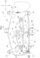
Fig. 3 is a plan view of a mower unit, -
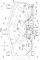
Fig. 4 is a lower side view of the mower, -
Fig. 5 is a side view in horizontal section of a water discharging section, -
Fig. 6 is a side view showing an arrangement of the water discharging section, -
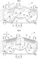
Fig. 7 is a lower side view showing an arrangement of a mower unit according to a further embodiment, -
Fig. 8 is a lower side view showing an arrangement of a mower unit according to a further embodiment, and -
Fig. 9 is an overall side view of a riding grass mowing machine according to a further embodiment. - Next, a mower unit relating to the present invention will be explained with reference to the accompanying drawings, by way of an example in which the mower unit is mounted on a riding grass mowing machine called a zero-turn mower. In this embodiment, when the front/rear direction of the machine body is to be defined, this definition will be made along the machine body advancing direction at a utility work state. Whereas, when the left/right direction of the machine body is to be defined, this definition will be made as seen in the machine body advancing direction. Namely, the direction denoted with a sign (F) in
Fig. 1 , etc. will be defined as the machine body front side, the direction denoted with a sign (B) inFig. 1 , etc. will be defined as the machine body rear side, the direction denoted with a sign (L) inFig. 2 , etc. will be defined as the machine body left side, and the direction denoted with a sign (R) inFig. 2 , etc. will be defined as the machine body right side, respectively. - As shown in
Fig. 1 andFig. 2 , in this embodiment, amower unit 20 is a side-discharge mower configured such that a traveling machine body includes left and right front wheels 1 and left and rightrear wheels 2, and between the front wheels 1 and therear wheels 2 of avehicle body frame 3 of this traveling machine body, themower unit 20 is mounted via alink mechanism 4 to the lower side of a drivingsection floor 16. - The traveling machine body includes, in addition to the left and right front wheels 1 and the left and right pair of
rear wheels 2, an engine section having anengine 5 and provided at a rear portion of the vehicle body, a driving section having a driver'sseat 6 and a pair of left and right maneuvering levers 7, a ROPS (Roll-Over Protective Structure)frame 8 disposed adjacent the rear side of the driver'sseat 6, atransmission device 9 supporting the left and rightrear wheels 2, and arotational shaft 11 for transmitting driving power of a PTO shaft 10 disposed at a front portion of thetransmission device 9 to ablade driving mechanism 30 of themower unit 20. - The left and right front wheels 1 are supported to an end portion of a front
wheel support frame 12 coupled to a front portion of thevehicle body frame 3 to be pivotable about a vertical axis via frontwheel support forks 13. The left and right front wheels 1 are freely pivoted relative to the frontwheel support frame 12 together with the frontwheel support forks 13. The left and rightrear wheels 2 are driven independently of each other by a pair of hydrostatic stepless speed changer device (not shown) included in thetransmission device 9 and are speed-changed independently of each other to the forward traveling side and reverse traveling side and also stopped by separate speed changing operations of the pair of hydrostatic stepless speed changer devices by the pair of left and right maneuvering levers 7. - The
link mechanism 4 is configured as follows. Namely, a single-actiontype lift cylinder 14 is coupled to adrive arm 19 connected to thelink mechanism 4 and as thelift cylinder 14 is expanded with feeding of pressure oil thereto, thelink mechanism 4 is elevated relative to the vehicle body frame, whereas as the cylinder is contracted with discharging of pressure oil therefrom, thelink mechanism 4 is lowered by the weight of its own relative to thevehicle body frame 3. - Namely, by contracting and expanding the
lift cylinder 14, themower unit 20 can be lowered to a work posture where left andright gauge wheels 25 provided rearwardly of themower unit 20 are placed in approximate contact with the ground surface for effecting a reaping work or themower unit 20 can be elevated to a non-work posture where thegauge wheels 25 are lifted off the ground surface not to effect any reaping work. - When the
mower unit 20 is set to the work posture and the traveling machine body is caused to travel, themower unit 20 will effect a reaping work of reaping grass or lawn by means of threeblades housing 21, and cut grass pieces will be conveyed by air current generated in association with rotation of eachblade discharge opening 23 disposed at the right end of thehousing 21 to be discharged to the outside of the traveling machine body. - As shown in
Fig. 3 andFig. 4 , themower unit 20 includes, in addition to thehousing 21, the threeblades gauge wheels 25, avertical wall portion 50 having an arcuate shape along the outer shape of the rotational trajectories of therespective blades discharge opening 23 formed at the right end of thehousing 21, aground contacting roller 36 disposed forwardly of thehousing 21, and a pair ofground contacting rollers 37 disposed rearwardly of thehousing 21. - As shown in
Fig. 3 , of the left andright gauge wheels 25 disposed rearwardly of themower unit 20, theleft gauge wheel 25 is disposed on the left rear side of thehousing 21 and supported to asupport member 25a having an approximately L-shape as seen in a plan view. Theright gauge wheel 25 is disposed on the right rear side of thehousing 21. - The
ground contacting roller 36 is disposed forwardly of the center portion in the width direction of thehousing 21. The pair ofground contacting rollers 37 are disposed rearwardly of the center portion in the width direction of thehousing 21 and disposed side by side in the width direction of thehousing 21. - As shown in
Fig. 3 andFig. 4 , thehousing 21 is constituted of aceiling wall 21a and a side wall and configured to cover theblades front side wall 21b extending from the front edge portion of theceiling wall 21a downwardly of thehousing 21, arear side wall 21c extending from the rear edge portion of theceiling wall 21a downwardly of thehousing 21 and alateral side wall 21d extending from the lateral end portion of theceiling wall 21a downwardly of thehousing 21. - The
discharge opening 23 is formed by the right end of theceiling wall 21a, the right end of thefront side wall 21b and the right end of thevertical wall portion 50. - The
rear side wall 21c is provided along the respective rear ends ofarcuate portions vertical wall portion 50 and rearwardly of thearcuate portions arcuate portion 50C is located forwardly of therear side wall 21c. - The three
blades housing 21 and side by side in the width direction thereof. The threeblades blade 22C located at the center in the width direction of thehousing 21 of the threeblades blade 22L is present most distantly from thedischarge opening 23 and located on the most upstream side in the cut grass flowing direction. Theblade 22R is located nearest thedischarge opening 23 and on the most downstream side in the cut grass flowing direction. - The
blades drive shafts ceiling wall 21a of thehousing 21 via unillustrated support members constituted of bearing support cases. With this arrangement, theblades drive shafts housing 21. Incidentally, each one of theblades cutter blades 28 provided at its opposed ends andwind generating blades 29 provided on the rear sides of therespective cutter blades 28. - The
vertical wall portion 50 has an arrangement thatarcuate portions respective blades blades arcuate portions lid body 60 is provided to extend forwardly from the lower end of thevertical wall portion 50 in such a manner as to cover a space S formed between thevertical wall portion 50 and therear side wall 21c. - The driving power from the engine 5 (see
Fig. 1 ) is transmitted to theblade driving mechanism 30. Then, the driving power transmitted to theblade driving mechanism 30 drives thedrive shaft 27C of theblade 22C and drives also therespective drive shafts blades belt 31 wound around all the threedrive shafts respective blades Fig. 4 . - Cut grass pieces cut by the
respective blades wind generating blades 29 of therespective blades housing 21 toward one lateral end side thereof where thedischarge opening 23 is located and discharged via this discharge opening 23 to the lateral outer side of thehousing 21. - As shown in
Figs 3 and4 , acleaning device 52 includes a singlewater feeding section 53 for feeding cleaning water, threewater discharging sections 54 for discharging the cleaning water to the inner wall face (corresponding to what is referred to as "ceiling face" in this invention) of theceiling wall 21a of thehousing 21, awater feeding pipe 55 connected to/between thewater discharging sections 54 and thewater feeding section 53. - As shown in
Fig. 3 , thewater feeding section 53 is supported to thewater feeding pipe 55. Thewater feeding pipe 55 is disposed upwardly of thehousing 21 and at a position on the left side in the width direction of thehousing 21. - On the outer wall face of the
housing 21, there is provided aprotection portion 40 for protecting thewater feeding section 53. In this embodiment, theprotection portion 40 is constituted of afirst protection member 40a provided on the left side of thewater feeding section 53 in the width direction thereof and asecond protection member 40b provided on the right side of thewater feeding section 53 in the width direction thereof. Namely, an arrangement is made such that thewater feeding section 53 is located between thefirst protection member 40a and thesecond protection member 40b as seen in a plan view. - Each one of the
first protection member 40a and thesecond protection member 40b is constituted of a bar-like member and provided in the form of a bridge extending from a more front side than thewater feeding section 53 to theleft support member 25a. Thefirst protection member 40a and thesecond protection member 40b are formed such that heights of the upper ends of thefirst protection member 40a and thesecond protection member 40b are higher than the height of the upper end of thewater feeding section 53. - As shown in
Fig. 3 andFig. 4 , thewater feeding pipe 55 includes a mainwater feeding pipe 56 connected to thewater feeding section 53 and three branchwater feeding pipes 57 branching from the mainwater feeding pipe 56 and connected respectively to thewater discharging sections 54. - As shown in
Fig. 3 andFig. 6 , the mainwater feeding pipe 56 extends rearwards and downwards from thewater feeding section 53 and is bent at a firstbent portion 56a adjacent theceiling wall 21a of thehousing 21. Further, the mainwater feeding pipe 56 extends from the firstbent portion 56a to the rear side of therear side wall 21c and is bent at a secondbent portion 56b and extends in the horizontal direction on the rear side of therear side wall 21c. - In the
water feeding pipe 55, there are provided astay 62a at the downstream end portion in the water flowing direction of the mainwater feeding pipe 56 and astay 62b at a position located between the secondbent portion 56b of the mainwater feeding pipe 56 and thestay 62a. Thestays rear side wall 21c corresponding to the bolt holes are fastened by abolt 63 to each other, thewater feeding pipe 55 is supported to therear side wall 21c. - As shown in
Fig. 4 , the mainwater feeding pipe 56 includes threebranch connecting portions 56c which branch from the mainwater feeding pipe 56 and to which the branchwater feeding pipes 57 are respectively connected. Thebranch connecting portions 56c are formed integrally with the mainwater feeding pipe 56 and provided under an inclined state progressively away from the mainwater feeding pipe 56 toward the water flowing direction downstream side of the mainwater feeding pipe 56 from the branching point from the mainwater feeding pipe 56. - The branch
water feeding pipes 57 are constituted of flexible connection pipes such as rubber hoses, vinyl hoses, or the like and connected between respective leading end portions of the plurality ofbranch connecting portions 56c provided in the mainwater feeding pipe 56 and thewater discharging sections 54. The branchwater feeding pipes 57 are disposed in a space S formed between thevertical wall portion 50 and therear side wall 21c located on the side opposite to the side where theblades vertical wall portion 50. -
Fig.5 shows an attachment portion for thewater discharging sections 54. Eachwater discharging section 54, as being fitted in a throughhole 65 defined in each one of thearcuate portions vertical wall portion 50 and therear side wall 21c located on the side opposite to the side where theblades vertical wall portion 50. - As shown in
Fig. 4 andFig. 5 , thewater discharging section 54 is supported to thehousing 21 via thesupport member 61. Thesupport member 61 includes an L-shapedabutment member 61a placed in abutment against theceiling wall 21a and thevertical wall portion 50 and aperpendicular member 61b extending perpendicularly from theabutment member 61a. Theabutment member 61a extends downwards from the portion of thisabutment member 61a placed in contact with theceiling wall 21a. Thewater discharging section 54, as being fitted in the throughhole 65 defined at the portion of theabutment member 61a opposed to thevertical wall portion 50, is supported to the lower end portion of theperpendicular member 61b. - At the portion of the
abutment member 61a placed in abutment against theceiling wall 21a, anelongate hole 61c is formed. Thewater discharging section 54 is fastened and fixed by abolt 58 inserted in theelongate hole 61c and a fastening hole (not shown) defined in theceiling wall 21a and anut 59. With this arrangement, the water discharging section54 is posture-adjustable within the hole range of theelongate hole 61c. - Each
water discharging section 54 is supported with an inclination such that thewater discharging section 54 approaches theceiling wall 21a as extending toward the water discharging outlet. And, thewater discharging sections 54 discharge cleaning water at least to the portions of theceiling wall 21a overlapped with the rotational trajectories TR, TC, TL (seeFig. 4 ) of theblades - As shown in
Fig. 4 , for instance, if cleaning water is fed to thewater feeding section 53 by connecting an unillustrated hose from a water tap to thewater feeding section 53 will flow through thewater feeding pipe 55 to be fed to thewater discharging sections 54 and discharged toward theceiling wall 21a from the lateral direction to the inner wall face of theceiling wall 21a of thehousing 21. Incidentally, in case the cleaning water is discharged while theblades ceiling wall 21a onto theblades respective drive shafts housing 21 in an efficient manner. - Next, other embodiments having modifications made to the foregoing embodiment will be explained. The following other embodiments may be applied in a plurality of combinations to the foregoing embodiment, unless any contradiction results from such combining. Incidentally, the scope of the present invention is not limited to the contents of the respective embodiments.
- (1) In the foregoing embodiment, there was explained an example in which cleaning water is discharged to the inner wall face of the
ceiling wall 21a of thehousing 21. However, it may be any inner wall face of thehousing 21. For instance, the water may be discharged to the inner wall face of thefront side wall 21b or the corner portion at the border between the inner wall face of theceiling wall 21a and the inner wall face of thefront side wall 21b. Further, thewater discharging section 54 may be configured to discharge cleaning water to thevertical wall portion 50. - (2) In the foregoing embodiment, there was explained an example in which the
vertical wall portion 50 is provided on the inner rear side of thehousing 21. However, the present invention is not limited to the foregoing embodiment. For instance, thevertical wall portion 50 may be provided on the inner rear side of thehousing 21. In this case, thewater discharging sections 54 and the branchwater feeding pipes 57 may be disposed at portions located in the space formed between thevertical wall portion 50 and thefront side wall 21b of thehousing 21. Further alternatively, thehousing 21 may omit thevertical wall portion 50. - (3) In the foregoing embodiment, there was explained an example in which the
cleaning device 52 includes thewater feeding section 53, thewater feeding pipe 55 and thewater discharging sections 54. However, the present invention is not limited to the foregoing embodiment. For instance, as shown inFig. 7 , thecleaning device 52 may be configured such that each one of the plurality ofwater discharging sections 54 includes awater feeding section 53. Further, as shown inFig 7 , thewater discharging section 54 may be configured to discharge water in the direction along the direction of wind generated by the rotations of theblades - (4) In the foregoing embodiment, there was explained an example in which the main
water feeding pipe 56 is provided with the plurality ofwater discharging sections 54 via the branchwater feeding pipes 57. However, as shown inFig. 8 , a large number ofwater discharging sections 54 may be provided directly in the mainwater feeding pipe 56. In this case, the arrangement may be provided with a plurality ofwater feeding sections 53. - (5) In the foregoing embodiment, there was explained an example in which the
water feeding section 53 is disposed upwardly of thehousing 21 and at a position on the left side in the width direction of thehousing 21. However, the present invention is not limited to the foregoing embodiment. For instance, thewater feeding section 53 may be disposed on the left side or the center side in the width direction of thehousing 21 or may be disposed on the lateral outer side of thehousing 21. - (6) In the foregoing embodiment, there was explained an example in which the
protection portion 40 includes thefirst protection member 40a and thesecond protection member 40b. However, the present invention is not limited to the foregoing embodiment. For instance, theprotection portion 40 may be constituted of a single member having a cylindrical shape and an opened upper portion, and thewater feeding section 53 may be disposed at the center portion of the cylinder. Further alternatively, theprotection portion 40 may be omitted at all. Further alternatively, a plurality ofwater feeding sections 53 may be provided. In this case, eachwater feeding section 53 may be provided with aprotection portion 40. - (7) In the foregoing embodiment, there was explained an example in which three blades are provided. However, two or fewer blades, or four or more blades may be provided. And, in such case, the number of the
water discharging sections 54, the number ofbranch connecting portions 56c and the number of branchwater feeding pipes 57 may be different from the number of the blades. - (8) In the foregoing embodiment, there was explained an example in which each one of the
water discharging sections 54 is supported with an inclination to approach theceiling wall 21a at it extends toward the water discharging outlet, thereby to discharge cleaning water toward theceiling wall 21a. However, the present invention is not limited to the foregoing embodiment. For instance, thewater discharging section 54 may be disposed parallel with the wall face of theceiling wall 21a, whereas the water discharging outlet of thewater discharging section 54 may be opened in the obliquely upward direction so as to discharge the cleaning water toward theceiling wall 21a. - (9) In the foregoing embodiment, there was explained an example in which the
mower unit 20 according to the present invention is mounted to a zero-turn mower as a "riding grass mowing machine". However, the present invention is not limited to the foregoing embodiment. For instance, as shown inFig. 9 , themower unit 20 relating to the present invention may be mounted to atractor 100. - The present invention is not limited to the mower being configured as a side-discharge type, but may be configured as a mulching-type or a rear-discharge type, and so on.
-
- 20:
- mower unit
- 21:
- housing
- 22L, 22C, 22R:
- blade
- 40:
- protection portion
- 40a:
- first protection member
- 40b:
- second protection member
- 50:
- vertical wall portion
- 53:
- water feeding section
- 54:
- water discharging section
- 55:
- water feeding pipe
- 56:
- main water feeding pipe
- 57:
- branch water feeding pipe
- 56c:
- branch connecting portion
- S:
- space
- TC, TL,TR:
- rotational trajectory
- XL, XC, XR:
- rotational axis
Claims (6)
- A mower unit comprising:a blade (22R,22C,22L) rotatably driven about a rotational axis to be able to cut grass on the ground surface;a housing (21) covering the blade and having a lower face thereof opened;a water feeding section (53) provided outside the housing;a water discharging section (54) provided inside the housing for discharging cleaning water fed to the water feeding section; anda water feeding pipe (55) connected to/between the water feeding section and the water discharging section;wherein the water discharging section discharges water toward an inner wall face (21a) of the housing;wherein inside the housing (21), there is provided a vertical wall portion (50) having an arcuate shape along an outer shape of a rotational trajectory of the blade;wherein the water discharging section (54) is provided at a portion located in a space (S) formed between the vertical wall portion (50) and a rear side wall (21c) of the housing (21);wherein the water feeding pipe (55) includes a main water feeding pipe (56) connected to the water feeding section (53) and a branch water feeding pipe (57) branching from the main water feeding pipe and connected to the water discharging section; andwherein the water discharging section (54) is fitted in a through hole (65) in the vertical wall portion (50),characterized in thatthere is provided a support member (61) for supporting the water discharging section (54) to the housing (21); andthe support member has an elongate hole (61c) for insertion of a bolt (58) for fixing and fastening the support member to the housing, the support member being adjustable in its posture within the range of the hole of the elongate hole.
- The mower unit of claim 1, wherein the water discharging section (54) discharges water toward a ceiling face of the inner wall face (21a).
- The mower unit of claim 1 or 2, wherein the water discharging section (54) discharges water toward at least a portion of the inner wall face overlapped with the rotational trajectory of the blade (22R,22C,22L) as seen in a plan view.
- The mower unit of any one of claims 1-3, wherein:the main water feeding pipe (56) includes a branch connecting portion (56c) formed integrally with the main water feeding pipe, to which the branch water feeding pipe (57) is connected; andthe branch connecting portion (56c) is provided under an inclined state progressively away from the main water feeding pipe (56) from a branching point toward the downstream side in a water flowing direction of the main water feeding pipe.
- The mower unit of any one of claims 1-4, wherein the water feeding section (53) is configured to discharge water toward the direction along a flowing direction of air current generated in association with rotation of the blade.
- The mower unit of any one of claims 1-5, wherein the water feeding section (53) is provided in a front side wall of the housing (21).
Applications Claiming Priority (2)
| Application Number | Priority Date | Filing Date | Title |
|---|---|---|---|
| JP2020213820A JP7413244B2 (en) | 2020-12-23 | 2020-12-23 | mower unit |
| EP21178851.8A EP4018804B1 (en) | 2020-12-23 | 2021-06-10 | Mowing unit with integrated cleaning system |
Related Parent Applications (2)
| Application Number | Title | Priority Date | Filing Date |
|---|---|---|---|
| EP21178851.8A Division EP4018804B1 (en) | 2020-12-23 | 2021-06-10 | Mowing unit with integrated cleaning system |
| EP21178851.8A Division-Into EP4018804B1 (en) | 2020-12-23 | 2021-06-10 | Mowing unit with integrated cleaning system |
Publications (3)
| Publication Number | Publication Date |
|---|---|
| EP4233519A2 true EP4233519A2 (en) | 2023-08-30 |
| EP4233519A3 EP4233519A3 (en) | 2023-09-13 |
| EP4233519B1 EP4233519B1 (en) | 2025-08-27 |
Family
ID=76392188
Family Applications (2)
| Application Number | Title | Priority Date | Filing Date |
|---|---|---|---|
| EP21178851.8A Active EP4018804B1 (en) | 2020-12-23 | 2021-06-10 | Mowing unit with integrated cleaning system |
| EP23167890.5A Active EP4233519B1 (en) | 2020-12-23 | 2021-06-10 | Mowing unit with integrated cleaning system |
Family Applications Before (1)
| Application Number | Title | Priority Date | Filing Date |
|---|---|---|---|
| EP21178851.8A Active EP4018804B1 (en) | 2020-12-23 | 2021-06-10 | Mowing unit with integrated cleaning system |
Country Status (3)
| Country | Link |
|---|---|
| US (1) | US11937535B2 (en) |
| EP (2) | EP4018804B1 (en) |
| JP (1) | JP7413244B2 (en) |
Families Citing this family (1)
| Publication number | Priority date | Publication date | Assignee | Title |
|---|---|---|---|---|
| JP2024090841A (en) * | 2022-12-23 | 2024-07-04 | 株式会社クボタ | Mower and work machine equipped with mower |
Citations (1)
| Publication number | Priority date | Publication date | Assignee | Title |
|---|---|---|---|---|
| JP2011205946A (en) | 2010-03-29 | 2011-10-20 | Kubota Corp | Riding type mower |
Family Cites Families (15)
| Publication number | Priority date | Publication date | Assignee | Title |
|---|---|---|---|---|
| US2936563A (en) * | 1956-09-26 | 1960-05-17 | Sunbeam Corp | Rotary lawnmower and attachment therefor |
| US3214893A (en) * | 1963-04-30 | 1965-11-02 | Griffin William Leslie | Lawn mower cleaner |
| US3568421A (en) * | 1968-03-12 | 1971-03-09 | Mcdonough Power Equipment Inc | Lawn mower |
| JPH0744880Y2 (en) * | 1988-04-20 | 1995-10-11 | 昭和アルミニウム株式会社 | Heat exchanger |
| JPH02131819U (en) * | 1989-03-31 | 1990-11-01 | ||
| US5499492A (en) * | 1992-03-05 | 1996-03-19 | Jameson; Eddie A. | Lawn mower cleaning method and attachment |
| JPH08294316A (en) * | 1995-04-27 | 1996-11-12 | Kubota Corp | Riding lawn mower |
| US6910320B1 (en) * | 2000-06-20 | 2005-06-28 | Deere & Company | Cleaning device for a mower cutting chamber |
| DE60313051T2 (en) * | 2003-04-28 | 2007-07-12 | Mtd Products Inc., Valley City | Mower housing with nozzle |
| JP4598716B2 (en) * | 2006-05-08 | 2010-12-15 | 株式会社クボタ | Riding mower |
| JP4957358B2 (en) * | 2007-04-27 | 2012-06-20 | 株式会社日立製作所 | Steam turbine cylinder connection pipe |
| JP5534199B2 (en) * | 2010-06-10 | 2014-06-25 | 株式会社アテックス | Mower deck cleaning equipment |
| JP6509060B2 (en) * | 2015-07-13 | 2019-05-08 | 株式会社クボタ | Mowing machine |
| US11102928B2 (en) * | 2017-07-13 | 2021-08-31 | Kubota Corporation | Electric work vehicle and mower unit |
| JP7226704B2 (en) * | 2018-06-19 | 2023-02-21 | 株式会社クボタ | work machine |
-
2020
- 2020-12-23 JP JP2020213820A patent/JP7413244B2/en active Active
-
2021
- 2021-06-10 EP EP21178851.8A patent/EP4018804B1/en active Active
- 2021-06-10 EP EP23167890.5A patent/EP4233519B1/en active Active
- 2021-06-15 US US17/348,058 patent/US11937535B2/en active Active
Patent Citations (1)
| Publication number | Priority date | Publication date | Assignee | Title |
|---|---|---|---|---|
| JP2011205946A (en) | 2010-03-29 | 2011-10-20 | Kubota Corp | Riding type mower |
Also Published As
| Publication number | Publication date |
|---|---|
| JP2022099810A (en) | 2022-07-05 |
| EP4018804A1 (en) | 2022-06-29 |
| EP4233519B1 (en) | 2025-08-27 |
| US20220192086A1 (en) | 2022-06-23 |
| US11937535B2 (en) | 2024-03-26 |
| JP7413244B2 (en) | 2024-01-15 |
| EP4233519A3 (en) | 2023-09-13 |
| EP4018804B1 (en) | 2024-11-13 |
Similar Documents
| Publication | Publication Date | Title |
|---|---|---|
| US6192666B1 (en) | Lawn mower | |
| EP3295784B1 (en) | Mid-mount riding grass mower | |
| US9476334B2 (en) | Working vehicle | |
| US7527298B2 (en) | Dust fender for riding type work vehicle | |
| EP4018804B1 (en) | Mowing unit with integrated cleaning system | |
| US10667464B2 (en) | Mower unit | |
| US8087221B2 (en) | Mower unit with washing device suspended from a grass mower | |
| US11666000B2 (en) | Riding-type mower | |
| US11148518B2 (en) | Electric work vehicle arrangement | |
| CN101472464A (en) | Combine | |
| JP6104031B2 (en) | Harvesting machine | |
| JP2013126389A (en) | Pre-harvesting treatment device of corn harvester | |
| JP6815280B2 (en) | Mower | |
| JP4860341B2 (en) | Work vehicle | |
| JP2010124787A (en) | Combine harvester | |
| EP3941182A1 (en) | Clog cleaning assembly for a lawn care vehicle | |
| JP2007302140A (en) | Battery mounting device for working vehicle | |
| CN211531854U (en) | Working vehicle | |
| JP2007309267A (en) | Working vehicle | |
| JP7068833B2 (en) | Harvester | |
| JP2021185793A (en) | Combine-harvester | |
| JP2003169520A (en) | Mower | |
| JP4798656B2 (en) | Work vehicle | |
| JP2022039645A (en) | Combine traveling frame structure | |
| KR20170054067A (en) | sub mower for boarding type mower |
Legal Events
| Date | Code | Title | Description |
|---|---|---|---|
| PUAI | Public reference made under article 153(3) epc to a published international application that has entered the european phase |
Free format text: ORIGINAL CODE: 0009012 |
|
| STAA | Information on the status of an ep patent application or granted ep patent |
Free format text: STATUS: REQUEST FOR EXAMINATION WAS MADE |
|
| REG | Reference to a national code |
Ref country code: DE Ref legal event code: R079 Free format text: PREVIOUS MAIN CLASS: A01D0034660000 Ipc: A01D0034000000 Ref document number: 602021037510 Country of ref document: DE |
|
| PUAL | Search report despatched |
Free format text: ORIGINAL CODE: 0009013 |
|
| 17P | Request for examination filed |
Effective date: 20230414 |
|
| AC | Divisional application: reference to earlier application |
Ref document number: 4018804 Country of ref document: EP Kind code of ref document: P |
|
| AK | Designated contracting states |
Kind code of ref document: A2 Designated state(s): AL AT BE BG CH CY CZ DE DK EE ES FI FR GB GR HR HU IE IS IT LI LT LU LV MC MK MT NL NO PL PT RO RS SE SI SK SM TR |
|
| AK | Designated contracting states |
Kind code of ref document: A3 Designated state(s): AL AT BE BG CH CY CZ DE DK EE ES FI FR GB GR HR HU IE IS IT LI LT LU LV MC MK MT NL NO PL PT RO RS SE SI SK SM TR |
|
| RIC1 | Information provided on ipc code assigned before grant |
Ipc: A01D 34/66 20060101ALI20230809BHEP Ipc: A01D 34/00 20060101AFI20230809BHEP |
|
| GRAP | Despatch of communication of intention to grant a patent |
Free format text: ORIGINAL CODE: EPIDOSNIGR1 |
|
| STAA | Information on the status of an ep patent application or granted ep patent |
Free format text: STATUS: GRANT OF PATENT IS INTENDED |
|
| RIC1 | Information provided on ipc code assigned before grant |
Ipc: A01D 34/66 20060101ALI20250311BHEP Ipc: A01D 34/00 20060101AFI20250311BHEP |
|
| INTG | Intention to grant announced |
Effective date: 20250331 |
|
| GRAS | Grant fee paid |
Free format text: ORIGINAL CODE: EPIDOSNIGR3 |
|
| GRAA | (expected) grant |
Free format text: ORIGINAL CODE: 0009210 |
|
| STAA | Information on the status of an ep patent application or granted ep patent |
Free format text: STATUS: THE PATENT HAS BEEN GRANTED |
|
| AC | Divisional application: reference to earlier application |
Ref document number: 4018804 Country of ref document: EP Kind code of ref document: P |
|
| AK | Designated contracting states |
Kind code of ref document: B1 Designated state(s): AL AT BE BG CH CY CZ DE DK EE ES FI FR GB GR HR HU IE IS IT LI LT LU LV MC MK MT NL NO PL PT RO RS SE SI SK SM TR |
|
| REG | Reference to a national code |
Ref country code: CH Ref legal event code: EP |
|
| REG | Reference to a national code |
Ref country code: DE Ref legal event code: R096 Ref document number: 602021037510 Country of ref document: DE |
|
| REG | Reference to a national code |
Ref country code: IE Ref legal event code: FG4D |
|
| REG | Reference to a national code |
Ref country code: NL Ref legal event code: MP Effective date: 20250827 |
|
| PG25 | Lapsed in a contracting state [announced via postgrant information from national office to epo] |
Ref country code: IS Free format text: LAPSE BECAUSE OF FAILURE TO SUBMIT A TRANSLATION OF THE DESCRIPTION OR TO PAY THE FEE WITHIN THE PRESCRIBED TIME-LIMIT Effective date: 20251227 |
|
| PG25 | Lapsed in a contracting state [announced via postgrant information from national office to epo] |
Ref country code: NO Free format text: LAPSE BECAUSE OF FAILURE TO SUBMIT A TRANSLATION OF THE DESCRIPTION OR TO PAY THE FEE WITHIN THE PRESCRIBED TIME-LIMIT Effective date: 20251127 |
|
| REG | Reference to a national code |
Ref country code: LT Ref legal event code: MG9D |
|
| PG25 | Lapsed in a contracting state [announced via postgrant information from national office to epo] |
Ref country code: PT Free format text: LAPSE BECAUSE OF FAILURE TO SUBMIT A TRANSLATION OF THE DESCRIPTION OR TO PAY THE FEE WITHIN THE PRESCRIBED TIME-LIMIT Effective date: 20251229 |
|
| PG25 | Lapsed in a contracting state [announced via postgrant information from national office to epo] |
Ref country code: FI Free format text: LAPSE BECAUSE OF FAILURE TO SUBMIT A TRANSLATION OF THE DESCRIPTION OR TO PAY THE FEE WITHIN THE PRESCRIBED TIME-LIMIT Effective date: 20250827 |
|
| PG25 | Lapsed in a contracting state [announced via postgrant information from national office to epo] |
Ref country code: HR Free format text: LAPSE BECAUSE OF FAILURE TO SUBMIT A TRANSLATION OF THE DESCRIPTION OR TO PAY THE FEE WITHIN THE PRESCRIBED TIME-LIMIT Effective date: 20250827 Ref country code: NL Free format text: LAPSE BECAUSE OF FAILURE TO SUBMIT A TRANSLATION OF THE DESCRIPTION OR TO PAY THE FEE WITHIN THE PRESCRIBED TIME-LIMIT Effective date: 20250827 |
|
| PG25 | Lapsed in a contracting state [announced via postgrant information from national office to epo] |
Ref country code: GR Free format text: LAPSE BECAUSE OF FAILURE TO SUBMIT A TRANSLATION OF THE DESCRIPTION OR TO PAY THE FEE WITHIN THE PRESCRIBED TIME-LIMIT Effective date: 20251128 |
|
| PG25 | Lapsed in a contracting state [announced via postgrant information from national office to epo] |
Ref country code: SE Free format text: LAPSE BECAUSE OF FAILURE TO SUBMIT A TRANSLATION OF THE DESCRIPTION OR TO PAY THE FEE WITHIN THE PRESCRIBED TIME-LIMIT Effective date: 20250827 |
|
| PG25 | Lapsed in a contracting state [announced via postgrant information from national office to epo] |
Ref country code: LV Free format text: LAPSE BECAUSE OF FAILURE TO SUBMIT A TRANSLATION OF THE DESCRIPTION OR TO PAY THE FEE WITHIN THE PRESCRIBED TIME-LIMIT Effective date: 20250827 |
|
| PG25 | Lapsed in a contracting state [announced via postgrant information from national office to epo] |
Ref country code: BG Free format text: LAPSE BECAUSE OF FAILURE TO SUBMIT A TRANSLATION OF THE DESCRIPTION OR TO PAY THE FEE WITHIN THE PRESCRIBED TIME-LIMIT Effective date: 20250827 Ref country code: PL Free format text: LAPSE BECAUSE OF FAILURE TO SUBMIT A TRANSLATION OF THE DESCRIPTION OR TO PAY THE FEE WITHIN THE PRESCRIBED TIME-LIMIT Effective date: 20250827 |
|
| PG25 | Lapsed in a contracting state [announced via postgrant information from national office to epo] |
Ref country code: RS Free format text: LAPSE BECAUSE OF FAILURE TO SUBMIT A TRANSLATION OF THE DESCRIPTION OR TO PAY THE FEE WITHIN THE PRESCRIBED TIME-LIMIT Effective date: 20251127 |
|
| PG25 | Lapsed in a contracting state [announced via postgrant information from national office to epo] |
Ref country code: ES Free format text: LAPSE BECAUSE OF FAILURE TO SUBMIT A TRANSLATION OF THE DESCRIPTION OR TO PAY THE FEE WITHIN THE PRESCRIBED TIME-LIMIT Effective date: 20250827 |
|
| REG | Reference to a national code |
Ref country code: AT Ref legal event code: MK05 Ref document number: 1828849 Country of ref document: AT Kind code of ref document: T Effective date: 20250827 |
|
| PG25 | Lapsed in a contracting state [announced via postgrant information from national office to epo] |
Ref country code: SM Free format text: LAPSE BECAUSE OF FAILURE TO SUBMIT A TRANSLATION OF THE DESCRIPTION OR TO PAY THE FEE WITHIN THE PRESCRIBED TIME-LIMIT Effective date: 20250827 |
|
| PG25 | Lapsed in a contracting state [announced via postgrant information from national office to epo] |
Ref country code: DK Free format text: LAPSE BECAUSE OF FAILURE TO SUBMIT A TRANSLATION OF THE DESCRIPTION OR TO PAY THE FEE WITHIN THE PRESCRIBED TIME-LIMIT Effective date: 20250827 |
|
| PG25 | Lapsed in a contracting state [announced via postgrant information from national office to epo] |
Ref country code: AT Free format text: LAPSE BECAUSE OF FAILURE TO SUBMIT A TRANSLATION OF THE DESCRIPTION OR TO PAY THE FEE WITHIN THE PRESCRIBED TIME-LIMIT Effective date: 20250827 |
|
| PG25 | Lapsed in a contracting state [announced via postgrant information from national office to epo] |
Ref country code: IT Free format text: LAPSE BECAUSE OF FAILURE TO SUBMIT A TRANSLATION OF THE DESCRIPTION OR TO PAY THE FEE WITHIN THE PRESCRIBED TIME-LIMIT Effective date: 20250827 |
|
| PG25 | Lapsed in a contracting state [announced via postgrant information from national office to epo] |
Ref country code: CZ Free format text: LAPSE BECAUSE OF FAILURE TO SUBMIT A TRANSLATION OF THE DESCRIPTION OR TO PAY THE FEE WITHIN THE PRESCRIBED TIME-LIMIT Effective date: 20250827 |
|
| PG25 | Lapsed in a contracting state [announced via postgrant information from national office to epo] |
Ref country code: SK Free format text: LAPSE BECAUSE OF FAILURE TO SUBMIT A TRANSLATION OF THE DESCRIPTION OR TO PAY THE FEE WITHIN THE PRESCRIBED TIME-LIMIT Effective date: 20250827 Ref country code: EE Free format text: LAPSE BECAUSE OF FAILURE TO SUBMIT A TRANSLATION OF THE DESCRIPTION OR TO PAY THE FEE WITHIN THE PRESCRIBED TIME-LIMIT Effective date: 20250827 |