EP4232330B1 - A ground effect flight vehicle - Google Patents
A ground effect flight vehicle Download PDFInfo
- Publication number
- EP4232330B1 EP4232330B1 EP21794250.7A EP21794250A EP4232330B1 EP 4232330 B1 EP4232330 B1 EP 4232330B1 EP 21794250 A EP21794250 A EP 21794250A EP 4232330 B1 EP4232330 B1 EP 4232330B1
- Authority
- EP
- European Patent Office
- Prior art keywords
- vehicle
- engines
- ground effect
- assembly
- engine
- Prior art date
- Legal status (The legal status is an assumption and is not a legal conclusion. Google has not performed a legal analysis and makes no representation as to the accuracy of the status listed.)
- Active
Links
Images


Classifications
-
- B—PERFORMING OPERATIONS; TRANSPORTING
- B60—VEHICLES IN GENERAL
- B60V—AIR-CUSHION VEHICLES
- B60V1/00—Air-cushion
- B60V1/14—Propulsion; Control thereof
-
- B—PERFORMING OPERATIONS; TRANSPORTING
- B64—AIRCRAFT; AVIATION; COSMONAUTICS
- B64C—AEROPLANES; HELICOPTERS
- B64C29/00—Aircraft capable of landing or taking-off vertically, e.g. vertical take-off and landing [VTOL] aircraft
- B64C29/0008—Aircraft capable of landing or taking-off vertically, e.g. vertical take-off and landing [VTOL] aircraft having its flight directional axis horizontal when grounded
- B64C29/0016—Aircraft capable of landing or taking-off vertically, e.g. vertical take-off and landing [VTOL] aircraft having its flight directional axis horizontal when grounded the lift during taking-off being created by free or ducted propellers or by blowers
- B64C29/0025—Aircraft capable of landing or taking-off vertically, e.g. vertical take-off and landing [VTOL] aircraft having its flight directional axis horizontal when grounded the lift during taking-off being created by free or ducted propellers or by blowers the propellers being fixed relative to the fuselage
-
- B—PERFORMING OPERATIONS; TRANSPORTING
- B64—AIRCRAFT; AVIATION; COSMONAUTICS
- B64C—AEROPLANES; HELICOPTERS
- B64C29/00—Aircraft capable of landing or taking-off vertically, e.g. vertical take-off and landing [VTOL] aircraft
- B64C29/0008—Aircraft capable of landing or taking-off vertically, e.g. vertical take-off and landing [VTOL] aircraft having its flight directional axis horizontal when grounded
- B64C29/0016—Aircraft capable of landing or taking-off vertically, e.g. vertical take-off and landing [VTOL] aircraft having its flight directional axis horizontal when grounded the lift during taking-off being created by free or ducted propellers or by blowers
- B64C29/0033—Aircraft capable of landing or taking-off vertically, e.g. vertical take-off and landing [VTOL] aircraft having its flight directional axis horizontal when grounded the lift during taking-off being created by free or ducted propellers or by blowers the propellers being tiltable relative to the fuselage
-
- B—PERFORMING OPERATIONS; TRANSPORTING
- B64—AIRCRAFT; AVIATION; COSMONAUTICS
- B64C—AEROPLANES; HELICOPTERS
- B64C29/00—Aircraft capable of landing or taking-off vertically, e.g. vertical take-off and landing [VTOL] aircraft
- B64C29/0008—Aircraft capable of landing or taking-off vertically, e.g. vertical take-off and landing [VTOL] aircraft having its flight directional axis horizontal when grounded
- B64C29/0083—Aircraft capable of landing or taking-off vertically, e.g. vertical take-off and landing [VTOL] aircraft having its flight directional axis horizontal when grounded the lift during taking-off being created by several motors of different type
-
- B—PERFORMING OPERATIONS; TRANSPORTING
- B64—AIRCRAFT; AVIATION; COSMONAUTICS
- B64C—AEROPLANES; HELICOPTERS
- B64C35/00—Flying-boats; Seaplanes
- B64C35/006—Flying-boats; Seaplanes with lift generating devices
-
- B—PERFORMING OPERATIONS; TRANSPORTING
- B64—AIRCRAFT; AVIATION; COSMONAUTICS
- B64C—AEROPLANES; HELICOPTERS
- B64C35/00—Flying-boats; Seaplanes
- B64C35/008—Amphibious sea planes
-
- B—PERFORMING OPERATIONS; TRANSPORTING
- B64—AIRCRAFT; AVIATION; COSMONAUTICS
- B64C—AEROPLANES; HELICOPTERS
- B64C39/00—Aircraft not otherwise provided for
- B64C39/12—Canard-type aircraft
-
- B—PERFORMING OPERATIONS; TRANSPORTING
- B64—AIRCRAFT; AVIATION; COSMONAUTICS
- B64D—EQUIPMENT FOR FITTING IN OR TO AIRCRAFT; FLIGHT SUITS; PARACHUTES; ARRANGEMENT OR MOUNTING OF POWER PLANTS OR PROPULSION TRANSMISSIONS IN AIRCRAFT
- B64D27/00—Arrangement or mounting of power plants in aircraft; Aircraft characterised by the type or position of power plants
- B64D27/02—Aircraft characterised by the type or position of power plants
- B64D27/30—Aircraft characterised by electric power plants
- B64D27/31—Aircraft characterised by electric power plants within, or attached to, wings
-
- B—PERFORMING OPERATIONS; TRANSPORTING
- B64—AIRCRAFT; AVIATION; COSMONAUTICS
- B64D—EQUIPMENT FOR FITTING IN OR TO AIRCRAFT; FLIGHT SUITS; PARACHUTES; ARRANGEMENT OR MOUNTING OF POWER PLANTS OR PROPULSION TRANSMISSIONS IN AIRCRAFT
- B64D27/00—Arrangement or mounting of power plants in aircraft; Aircraft characterised by the type or position of power plants
- B64D27/02—Aircraft characterised by the type or position of power plants
- B64D27/30—Aircraft characterised by electric power plants
- B64D27/32—Aircraft characterised by electric power plants within, or attached to, fuselages
-
- B—PERFORMING OPERATIONS; TRANSPORTING
- B64—AIRCRAFT; AVIATION; COSMONAUTICS
- B64D—EQUIPMENT FOR FITTING IN OR TO AIRCRAFT; FLIGHT SUITS; PARACHUTES; ARRANGEMENT OR MOUNTING OF POWER PLANTS OR PROPULSION TRANSMISSIONS IN AIRCRAFT
- B64D27/00—Arrangement or mounting of power plants in aircraft; Aircraft characterised by the type or position of power plants
- B64D27/02—Aircraft characterised by the type or position of power plants
- B64D27/30—Aircraft characterised by electric power plants
- B64D27/34—All-electric aircraft
-
- B—PERFORMING OPERATIONS; TRANSPORTING
- B64—AIRCRAFT; AVIATION; COSMONAUTICS
- B64C—AEROPLANES; HELICOPTERS
- B64C35/00—Flying-boats; Seaplanes
- B64C35/001—Flying-boats; Seaplanes with means for increasing stability on the water
Definitions
- the invention relates to a flight vehicle comprising, a fuselage, a wing assembly, an engine assembly comprising one or more engines, and a hull for enabling floatation of the vehicle.
- a disadvantage of the known amphibious flight vehicle of WO88/00898 is that it requires all the features of a helicopter, and additional engines to provide propellant force for cruise flight.
- the known flight vehicle is therefore less efficient (in terms of energy and space) than an ordinary wing in ground effect (WIG) vehicle because of its rotor system and the large opening on the main wing/fuselage and more complicated, expensive, and difficult to control during flight.
- WIG ground effect
- RU2264951C1 teaches a ground-effect craft with a low-wing monoplane, mid-wing monoplane and high-wing monoplane arranged in tandem. Mounted on their outer panels are annular channels equipped with turning units and cantilever propellers for creating vertical and horizontal thrust.
- the ground effect rotorcraft comprises a fuselage), a rotor system, ground effect wings, side end plates, an empennage, an engine and a transmission and tilting system.
- the ground-effect wings are symmetrically arranged on the two sides of the fuselage, the side end plates are arranged on the outer sides of the low-effect wings respectively, the empennage is located behind the fuselage, the at least two pairs of rotor systems are symmetrically arranged on the empennage and the side end plates respectively, and the engine is connected with the transmission and tilting system and the rotor systems.
- the ground effect rotorcraft has a vertical take-off and landing function.
- a wing in ground effect vehicle comprising a fuselage, a wing assembly, an engine assembly comprising one or more engines or engine sets, and a hull for enabling floatation of the vehicle; wherein the wing assembly comprises positionable stabilizer wings and/or the one or more engines are equipped to provide an airflow departing from the engines which is directable in one of multiple directions, a first direction of the multiple directions which is arranged to generate lift for vertical take-off purpose, and a second direction of the multiple directions which is for horizontal cruise flight in and out of ground effect, wherein the vehicle has apertures to enable passing of air propelled by the engine assembly when the airflow departing from one or more engines is directed in the first direction.
- US2011/0266081 aims to increase the vehicle's lift by blowing air with the propulsors located on or at the wings. As a benefit the vehicle has VTOL capability. However, at high speeds both the air coming from the front of the wing and from the propulsors will mainly be trapped at the trailing edge of the wing and create a bow-down pitch moment. Since the propulsors are designed to be blowing air under the wings in all positions, this will limit the designed maximum speed of the vehicle. Further the full thrust of the propulsors cannot be dedicated for propelling the vehicle. Some of the available thrust is at all times sacrificed for lift in all positions of the propulsors. In the system of US2011/0266081 there is always an upwards component of the thrust vector, and the resultant thrust vector cannot be horizontal.
- the resultant thrust vector can be arranged to be horizontal or that even some downward component can be achieved during flight for small arrangements on the flight (trim) angle.
- a major advantage of the ground effect vehicle of the invention is that it is able to take-off and land on areas that are above the sea level such as petrol platforms, aircraft carriers or ports. This eliminates the impact forces caused by the waves during take-off and landing, enhancing the vehicle's operational sea state.
- the ground effect vehicle of the invention comprises a fuselage 1; a wing assembly 4, 5; an engine assembly 6, 7, 8 comprising one or more engines; and a hull 2 for enabling floatation of the vehicle. Further there is a float assembly 3 to provide stability during floatation on a water surface.
- the ground effect vehicle may also be provided with a wheelset to enable vehicle to land on and depart from solid ground. The wheelset may for instance be integrated with the float assembly 3.
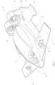
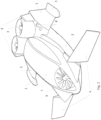
- the wing assembly 4, 5 comprises stabilizer wings 4, wherein a comparison between figure 1 and figure 2 shows that the stabilizer wings 4 are positionable and/or the one or more engines 7 are positionable so as to arrange that the airflow departing from the engines is directable in one of multiple directions.
- a first position of the engines which results in a corresponding direction of the airflow departing from the engines is best shown in figure 2 which is arranged to generate lift for vertical take-off purpose.
- a second position of the engines and a corresponding direction of the airflow departing from the engines is shown in figure 1 which is arranged for horizontal cruise flight.
- the one or more engines are therefore rotatably mounted on one of the fuselage 1 and the wing assembly, in particular the main wings 5.
- the rotatable mounting of the engines is schematically also shown in figure 6.1 , depicting also another option to provide that the airflow departing from the engines can be selectively arranged to flow in a desired direction, to note that figure 6.2 and figure 6.3 show schematically that the one or more engines can be equipped with a controllable thrust diversion mechanism.
- this thrust diversion mechanism By suitably controlling this thrust diversion mechanism it is possible to provide an airflow departing from the engines which is directable in one of multiple directions, a first direction of the multiple directions which is arranged to generate lift for vertical take-off purpose, and a second direction of the multiple directions which is for horizontal cruise flight.
- Figure 6.4 and figure 6.5 further show examples of closable apertures to prevent airflow from a lower side to an upper side of the vehicle and to optimize horizontal cruise flight of the vehicle.
- figure 3 which is a view from below at the vehicle shown in figure 2 , clearly shows that the vehicle has apertures 10 to enable passing of air propelled by the engine assembly when the one or more engines 7 are in the first or VTOL position.
- the apertures 10 are closable to avoid undesirable turbulence during cruise flight.
- both figure 1 and figure 5 show that in both embodiments of the ground effect vehicle of the invention the engine assembly comprises two or more engines 6, 7, 8 that are distributed over the wing assembly 4, 5 to allow directional control by differential powering up of said engines 6, 7, 8.
- the engine assembly 6, 7, 8 comprises different types of engines, a first type to meet requirements both for loiter/hover conditions, i.e. engine 6 and a second type sized for forward flight, i.e. engines 7, and a third type in the form of a booster to create an air cushion in an initial stage of take-off.
- the respective figures further show an aerodynamic fuselage 1 for carrying cargo/passengers, a hull 2 and an engine assembly 6, 7, 8 which comprises a forward propulsion engine set 6 which is located inside the fuselage 1 and on forward wings/canards 4 of the wing assembly 4, 5; and an aft propulsion engine set 7 which is located on a main wing 5 of the wing assembly 4, 5, and a secondary thruster or thrusters 8 to control three-dimensional motions of the vehicle.
- the secondary thruster or thrusters 8 are mounted on the forward wings/canards 4 which are tiltable.
- the hull 2 carries the fuselage 1 above the water surface/ground when stationary.
- the hull 2 shape can be a v-hull, stepped hull, catamaran, trimaran, multihull or comprising multiple separate floats.
- the hull 2 is designed in such a way that when the propulsion engine sets 6, 7 are blowing air under the vehicle, a complete or partial air cushion is created to hover the vehicle just above the sea surface/ground at zero forward speed or below take-off speed.
- the forward propulsion engine set 6 is arranged for maneuvering (roll, pitch, yaw), for hover/VTOL/STOL support and as additional booster.
- the secondary thruster or thrusters 8 are placed on a selected one of a group comprising the canards 4, main wings 5, and side floats 3 to control the three-dimensional motion (yaw, pitch, roll) of the vehicle.
- the aft propulsion engine set 7 comprises one or more tiltable propulsion engines which act as main thruster and maneuver control.
- the aft propulsion engine set 7 is directed downwards for blowing air under the main wings 5.
- the aft propulsion engine set 7 can be directed with an angle to obtain both lift and forward thrust during STOL.
- the aft propulsion engine set 7 is set to horizontal during cruise where the lift is created by the wings 4, 5.
- the applied propulsion units can be either ducted fan type, contra-rotating propellers, turbo fan or gas turbine.
- the propulsion units can be designed as tilted type or fixed type with an additional mechanism (i.e. thrust vectoring nozzle) for directing the thrust.
- the aft propulsion engine set 7 can also be used as ailerons by separate control of the thrust angle of each unit.
- the roll and yaw motions are preferably controlled by the aft propulsion engine set 7.
- the secondary thruster or thrusters 8 can be placed anywhere and in any desired number on the vehicle (i.e. on the canards, main wings, side floats etc.) to control the three-dimensional motion (yaw, pitch, roll) of the vehicle.
- the secondary thrusters 8 can also be used for creating additional lift or thrust.
- the engine assembly 6, 7, 8 can be arranged to be electrically powered.
Landscapes
- Engineering & Computer Science (AREA)
- Aviation & Aerospace Engineering (AREA)
- Chemical & Material Sciences (AREA)
- Combustion & Propulsion (AREA)
- Transportation (AREA)
- Mechanical Engineering (AREA)
- Toys (AREA)
- Aiming, Guidance, Guns With A Light Source, Armor, Camouflage, And Targets (AREA)
- Catching Or Destruction (AREA)
- Road Paving Structures (AREA)
- Vehicle Body Suspensions (AREA)
Description
- The invention relates to a flight vehicle comprising, a fuselage, a wing assembly, an engine assembly comprising one or more engines, and a hull for enabling floatation of the vehicle.
-
WO88/00898 - An example of a ground effect vehicle is provided by
US 5,335,742 . - In the following disclosure certain abbreviations may be used, which abbreviations have the meanings as provided below:
- VTOL: Vertical Take-off and landing at zero forward speed
- STOL: Short Take-off at low forward speed
- IMO: International Maritime Organisation
- Type A/B: Wing in Ground Effect type as described in IMO rules
- Air cushion: The lift effect of pressurized air being trapped between a vehicle and the ground/fixed surface.
- Cruise mode: The flight mode of the vehicle where more than 50% of the vertical lift is generated by the aerodynamic forces acting on the vehicle wings.
- Hover mode: The flight mode of the vehicle where more than 50% of the vertical lift is generated by the vehicle's propulsion units and/or the air cushion provided below the vehicle.
- A disadvantage of the known amphibious flight vehicle of
WO88/00898 -
RU2264951C1 -
CN110901906 relates to a rotorcraft capable of improving the cruise lift-drag ratio and the cruise speed by utilizing the ground effect principle. The ground effect rotorcraft comprises a fuselage), a rotor system, ground effect wings, side end plates, an empennage, an engine and a transmission and tilting system. The ground-effect wings are symmetrically arranged on the two sides of the fuselage, the side end plates are arranged on the outer sides of the low-effect wings respectively, the empennage is located behind the fuselage, the at least two pairs of rotor systems are symmetrically arranged on the empennage and the side end plates respectively, and the engine is connected with the transmission and tilting system and the rotor systems. The ground effect rotorcraft has a vertical take-off and landing function. -
WO2018/156041 relates to a vertical takeoff and landing propulsion system and aircraft, in particular to an aircraft with hybrid or electric drive, to be used for air travel of persons and air transport of goods, without the need of landing runways. The aircraft has a modular propulsion system consisting of three multiple propellers with flow amplifier, where the first fixed propeller is included in a fuselage in the front part of an enclosure provided with two ducts, an upper one and a lower one, communicating with the upper side wing and the lower side wing, respectively, the lower duct being controlled by some louvres which are in vertical position upon takeoff, directing the air jet downwards and are inclined during transition, directing the air jet backwards, where, during horizontal fight, the upper duct is closed by a flap and the lower duct by the louvres. - The prior art document
US2011/0266081 discloses a wing in ground effect vehicle comprising a fuselage, a wing assembly, an engine assembly comprising one or more engines or engine sets, and a hull for enabling floatation of the vehicle; wherein the wing assembly comprises positionable stabilizer wings and/or the one or more engines are equipped to provide an airflow departing from the engines which is directable in one of multiple directions, a first direction of the multiple directions which is arranged to generate lift for vertical take-off purpose, and a second direction of the multiple directions which is for horizontal cruise flight in and out of ground effect,
wherein the vehicle has apertures to enable passing of air propelled by the engine assembly when the airflow departing from one or more engines is directed in the first direction. -
US2011/0266081 aims to increase the vehicle's lift by blowing air with the propulsors located on or at the wings. As a benefit the vehicle has VTOL capability. However, at high speeds both the air coming from the front of the wing and from the propulsors will mainly be trapped at the trailing edge of the wing and create a bow-down pitch moment. Since the propulsors are designed to be blowing air under the wings in all positions, this will limit the designed maximum speed of the vehicle. Further the full thrust of the propulsors cannot be dedicated for propelling the vehicle. Some of the available thrust is at all times sacrificed for lift in all positions of the propulsors. In the system ofUS2011/0266081 there is always an upwards component of the thrust vector, and the resultant thrust vector cannot be horizontal. - It is an object of the invention that the resultant thrust vector can be arranged to be horizontal or that even some downward component can be achieved during flight for small arrangements on the flight (trim) angle.
- It is a further object of the invention to provide a less complicated, more efficient, and less expensive, yet easy to control amphibious flight vehicle, that is capable of using ground effect during cruise, and which is capable to generate sufficient power to ascend/descend vertically with no or very low forward speed, during takeoff and landing (VTOL/STOL).
- The ground effect vehicle of the invention is provided with the features of one or more of the appended claims.
- A major advantage of the ground effect vehicle of the invention is that it is able to take-off and land on areas that are above the sea level such as petrol platforms, aircraft carriers or ports. This eliminates the impact forces caused by the waves during take-off and landing, enhancing the vehicle's operational sea state.
- In the drawing:
-
figure 1 shows a first embodiment of an ground effect vehicle according to the invention in an isometric view in cruise control mode; -
figure 2 shows an isometric view the ground effect vehicle offigure 1 in VTOL mode; -
figure 3 shows the ground effect vehicle as shown infigure 2 with a view at the hull of the vehicle; -
figure 4 shows an exploded view of the first embodiment of the ground effect vehicle shown infigure 1 ; -
figure 5 shows a second embodiment of an ground effect vehicle according to the invention in several views; -
figures 6.1 - 6.3 show schematically different options to provide the airflow departing from the engines to be positionable in one of multiple positions; and -
figures 6.4 and 6.5 show the closable apertures to prevent airflow from a lower side to an upper side of the vehicle and to optimize horizontal cruise flight of the vehicle. - Whenever in the figures the same reference numerals are applied, these numerals refer to the same parts.
- With reference to the
figures 1 - 5 that are for a large part self-explanatory, it is shown that the ground effect vehicle of the invention comprises a fuselage 1; awing assembly 4, 5; anengine assembly 6, 7, 8 comprising one or more engines; and ahull 2 for enabling floatation of the vehicle. Further there is afloat assembly 3 to provide stability during floatation on a water surface. Optionally the ground effect vehicle may also be provided with a wheelset to enable vehicle to land on and depart from solid ground. The wheelset may for instance be integrated with thefloat assembly 3. - According to the invention the
wing assembly 4, 5 comprises stabilizer wings 4, wherein a comparison betweenfigure 1 andfigure 2 shows that the stabilizer wings 4 are positionable and/or the one or more engines 7 are positionable so as to arrange that the airflow departing from the engines is directable in one of multiple directions. A first position of the engines which results in a corresponding direction of the airflow departing from the engines is best shown infigure 2 which is arranged to generate lift for vertical take-off purpose. A second position of the engines and a corresponding direction of the airflow departing from the engines is shown infigure 1 which is arranged for horizontal cruise flight. The one or more engines are therefore rotatably mounted on one of the fuselage 1 and the wing assembly, in particular themain wings 5. - The rotatable mounting of the engines is schematically also shown in
figure 6.1 , depicting also another option to provide that the airflow departing from the engines can be selectively arranged to flow in a desired direction, to note thatfigure 6.2 and figure 6.3 show schematically that the one or more engines can be equipped with a controllable thrust diversion mechanism. By suitably controlling this thrust diversion mechanism it is possible to provide an airflow departing from the engines which is directable in one of multiple directions, a first direction of the multiple directions which is arranged to generate lift for vertical take-off purpose, and a second direction of the multiple directions which is for horizontal cruise flight. -
Figure 6.4 and figure 6.5 further show examples of closable apertures to prevent airflow from a lower side to an upper side of the vehicle and to optimize horizontal cruise flight of the vehicle. - Turning back to
figures 1 - 5 , it is remarked that during cruise flight when the stabilizer wings 4 and/or the one or more engines 7 are in the second position according tofigure 1 , said second position of the one or more engines 7 is tuneable so as to arrange for controlling movement of the vehicle in roll/pitch and yaw directions. - In particular
figure 3 , which is a view from below at the vehicle shown infigure 2 , clearly shows that the vehicle has apertures 10 to enable passing of air propelled by the engine assembly when the one or more engines 7 are in the first or VTOL position. - It is further desirable that the apertures 10 are closable to avoid undesirable turbulence during cruise flight.
- Both
figure 1 andfigure 5 show that in both embodiments of the ground effect vehicle of the invention the engine assembly comprises two ormore engines 6, 7, 8 that are distributed over thewing assembly 4, 5 to allow directional control by differential powering up of saidengines 6, 7, 8. - It is further beneficial that the
engine assembly 6, 7, 8 comprises different types of engines, a first type to meet requirements both for loiter/hover conditions,i.e. engine 6 and a second type sized for forward flight, i.e. engines 7, and a third type in the form of a booster to create an air cushion in an initial stage of take-off. - The respective figures further show an aerodynamic fuselage 1 for carrying cargo/passengers, a
hull 2 and anengine assembly 6, 7, 8 which comprises a forwardpropulsion engine set 6 which is located inside the fuselage 1 and on forward wings/canards 4 of thewing assembly 4, 5; and an aft propulsion engine set 7 which is located on amain wing 5 of thewing assembly 4, 5, and a secondary thruster or thrusters 8 to control three-dimensional motions of the vehicle. Preferably the secondary thruster or thrusters 8 are mounted on the forward wings/canards 4 which are tiltable. - The
hull 2 carries the fuselage 1 above the water surface/ground when stationary. Thehull 2 shape can be a v-hull, stepped hull, catamaran, trimaran, multihull or comprising multiple separate floats. Thehull 2 is designed in such a way that when the propulsion engine sets 6, 7 are blowing air under the vehicle, a complete or partial air cushion is created to hover the vehicle just above the sea surface/ground at zero forward speed or below take-off speed. - The forward propulsion engine set 6 is arranged for maneuvering (roll, pitch, yaw), for hover/VTOL/STOL support and as additional booster. The secondary thruster or thrusters 8 are placed on a selected one of a group comprising the canards 4,
main wings 5, and side floats 3 to control the three-dimensional motion (yaw, pitch, roll) of the vehicle. The aft propulsion engine set 7 comprises one or more tiltable propulsion engines which act as main thruster and maneuver control. During VTOL, the aft propulsion engine set 7 is directed downwards for blowing air under themain wings 5. The aft propulsion engine set 7 can be directed with an angle to obtain both lift and forward thrust during STOL. The aft propulsion engine set 7 is set to horizontal during cruise where the lift is created by thewings 4, 5. - The applied propulsion units can be either ducted fan type, contra-rotating propellers, turbo fan or gas turbine. The propulsion units can be designed as tilted type or fixed type with an additional mechanism (i.e. thrust vectoring nozzle) for directing the thrust. The aft propulsion engine set 7 can also be used as ailerons by separate control of the thrust angle of each unit. The roll and yaw motions are preferably controlled by the aft propulsion engine set 7.
- The secondary thruster or thrusters 8 can be placed anywhere and in any desired number on the vehicle (i.e. on the canards, main wings, side floats etc.) to control the three-dimensional motion (yaw, pitch, roll) of the vehicle. The secondary thrusters 8 can also be used for creating additional lift or thrust.
- Finally it is remarked that the
engine assembly 6, 7, 8 can be arranged to be electrically powered. - Although the invention has been discussed in the foregoing with reference to exemplary embodiments of an ground effect vehicle of the invention, the invention is not restricted to these particular embodiments which can be varied in many ways without departing from the invention. The discussed exemplary embodiments shall therefore not be used to construe the appended claims strictly in accordance therewith. On the contrary the embodiments are merely intended to explain the wording of the appended claims without intent to limit the claims to these exemplary embodiments. The scope of protection of the invention shall therefore be construed in accordance with the appended claims.
Claims (9)
- A ground effect vehicle comprising a fuselage (1), a wing assembly (4, 5), an engine assembly comprising one or more engines or engine sets (6, 7, 8), and a hull (2) for enabling floatation of the vehicle;wherein the wing assembly (4, 5) comprises positionable stabilizer wings (4) and/or the one or more engines (6, 7, 8) are equipped to provide an airflow departing from the engines (6, 7, 8) which is directable in one of multiple directions, a first direction of the multiple directions which is arranged to generate lift for vertical take-off purpose, and a second direction of the multiple directions which is for horizontal cruise flight in and out of ground effect,wherein the vehicle has apertures (10) to enable passing of air propelled by the engine assembly when the airflow departing from the one or more engines (6, 7) is directed in the first direction,wherein the engine assembly (6, 7, 8) comprises a forward propulsion engine set (6) which is located inside the fuselage (1) or on forward wings/canards (4) of the wing assembly (4, 5), and an aft propulsion engine set (7) which is located on a main wing (5) of the wing assembly (4, 5), and a secondary thruster or thrusters (8) to control three-dimensional motions of the vehicle, wherein the one or more engines (7) are rotatably mounted on the fuselage (1) and on the wing assembly (4, 5), wherein during cruise flight when the stabilizer wings (4) and/or the airflow departing from the one or more engines (7) is directed in the second direction, said second direction of the airflow departing from the one or more engines (7) is tuneable sc as to arrange for controlling movement of the vehicle in roll/pitch and yaw directions, and the apertures (10) are closable so as to prevent airflow from a lower side to an upper side of the vehicle so as to optimize horizontal cruise flight of the vehicle.
- The ground effect vehicle of claim 1, characterized in that the one or more engines (6, 7, 8) are equipped with a controllable thrust diversion mechanism.
- The ground effect vehicle of any one of claims 1-2, characterized in that the engine assembly (6, 7, 8) comprises two or more engines (7, 8) that are distributed over the wing assembly (4, 5) to allow directional control by differential powering up of said engines.
- The ground effect vehicle of any one of claims 1-3, characterized in that the engine assembly (6, 7, 8) comprises different types of engines, a first type to meet requirements both for loiter/hover conditions, a second type sized for forward flight, and a third type in the form of a booster to create an air cushion in an initial stage of take-off.
- The ground effect vehicle of any one of claims 1-4, characterized in that the forward propulsion engine set (6) is arranged for maneuvering (roll, pitch, yaw), for hover/VTOL/STOL support and as additional booster.
- The ground effect vehicle of any one of claims 1-5, characterized in that the secondary thruster or thrusters (8) are placed on a selected one of a group comprising the canards (4), main wings (5), and side floats (3) to control the three-dimensional motion (yaw, pitch, roll) of the vehicle.
- The ground effect vehicle of claim 6, characterized in that the secondary thruster or thrusters (8) are mounted on the forward wings/canards (4) which are tiltable.
- The ground effect vehicle of any one of claims 1-7, characterized in that the aft propulsion engine set (7) comprises one or more tiltable propulsion engines.
- The ground effect vehicle of any one of claims 1-8, characterized in that the engine assembly is electrically powered.
Applications Claiming Priority (2)
| Application Number | Priority Date | Filing Date | Title |
|---|---|---|---|
| NL2026721A NL2026721B1 (en) | 2020-10-21 | 2020-10-21 | An amphibious flight vehicle |
| PCT/NL2021/050618 WO2022086321A1 (en) | 2020-10-21 | 2021-10-12 | A ground effect flight vehicle |
Publications (3)
| Publication Number | Publication Date |
|---|---|
| EP4232330A1 EP4232330A1 (en) | 2023-08-30 |
| EP4232330B1 true EP4232330B1 (en) | 2024-08-14 |
| EP4232330C0 EP4232330C0 (en) | 2024-08-14 |
Family
ID=75252794
Family Applications (1)
| Application Number | Title | Priority Date | Filing Date |
|---|---|---|---|
| EP21794250.7A Active EP4232330B1 (en) | 2020-10-21 | 2021-10-12 | A ground effect flight vehicle |
Country Status (8)
| Country | Link |
|---|---|
| US (1) | US12252247B2 (en) |
| EP (1) | EP4232330B1 (en) |
| CN (1) | CN116583460A (en) |
| AU (1) | AU2021364858A1 (en) |
| CA (1) | CA3195776A1 (en) |
| ES (1) | ES2989623T3 (en) |
| NL (1) | NL2026721B1 (en) |
| WO (1) | WO2022086321A1 (en) |
Families Citing this family (3)
| Publication number | Priority date | Publication date | Assignee | Title |
|---|---|---|---|---|
| US12252243B2 (en) * | 2020-12-15 | 2025-03-18 | Honda Motor Co., Ltd. | Aircraft |
| WO2023136815A1 (en) * | 2022-01-11 | 2023-07-20 | Glen Newman | Evtol aircraft |
| CN117262214B (en) * | 2023-10-11 | 2024-07-05 | 哈尔滨工业大学 | Amphibious short take-off and landing ground effect vehicle |
Family Cites Families (20)
| Publication number | Priority date | Publication date | Assignee | Title |
|---|---|---|---|---|
| US3181810A (en) * | 1961-02-27 | 1965-05-04 | Curtiss Wright Corp | Attitude control system for vtol aircraft |
| US3159361A (en) * | 1962-02-14 | 1964-12-01 | Carl W Weiland | Aircraft |
| US5026002A (en) | 1986-06-13 | 1991-06-25 | Yarrington Arthur G | Helihover amphibious aircraft |
| DE3937240A1 (en) | 1989-11-09 | 1991-05-16 | Albert Blum | GROUND EFFECT VEHICLE |
| DE4219826A1 (en) * | 1992-06-17 | 1993-12-23 | Abs Int Sa | Control for a hovercraft |
| US5419514A (en) * | 1993-11-15 | 1995-05-30 | Duncan; Terry A. | VTOL aircraft control method |
| RU2264951C1 (en) * | 2004-02-24 | 2005-11-27 | Дуров Дмитрий Сергеевич | Hydroconverti ground-effect craft |
| EP1855942A2 (en) * | 2005-01-10 | 2007-11-21 | Urban Aeronautics Ltd. | Ducted fan vtol vehicles |
| EP2097317A1 (en) * | 2006-11-02 | 2009-09-09 | Severino Manuel Oliveira Raposo | System and process of vector propulsion with independent control of three translation and three rotation axis |
| DE102009004239A1 (en) * | 2009-01-05 | 2010-07-08 | Ivan Novikov-Kopp | Method for the complex increase of aerodynamic and transport properties, ground effect vehicle for carrying out the method (variants) and flight method |
| US8177162B2 (en) * | 2009-06-10 | 2012-05-15 | Jon Karkow | Wingtip and sponson interaction on an amphibious aircraft |
| US9809211B2 (en) * | 2015-03-24 | 2017-11-07 | Walter Schulz | Three stage watercraft |
| JP2017015527A (en) * | 2015-06-30 | 2017-01-19 | 株式会社トプコン | Wide area sensor system, flight detection method and program |
| GB2555439A (en) | 2016-10-27 | 2018-05-02 | Mono Aerospace Ip Ltd | Vertical take-off and landing aircraft and control method |
| RO132763A2 (en) * | 2017-02-22 | 2018-08-30 | Liviu Grigorian Giurcă | Vertical takeoff and landing propulsion system |
| US11724801B2 (en) * | 2017-11-03 | 2023-08-15 | Textron Systems Corporation | VTOL aircraft having fixed-wing and rotorcraft configurations |
| US11130568B2 (en) * | 2018-11-08 | 2021-09-28 | Textron Innovations Inc. | Autonomous thrust vectoring ring wing pod |
| US20200255136A1 (en) * | 2018-11-09 | 2020-08-13 | Karem Aircraft, Inc. | Vertical Flight Aircraft With Improved Stability |
| CN110901906B (en) * | 2019-12-04 | 2023-04-25 | 中国直升机设计研究所 | Ground effect rotor craft and flight mode switching method |
| US11479350B2 (en) * | 2020-06-19 | 2022-10-25 | Textron Innovations Inc. | Tip gap monitoring systems for ducted aircraft |
-
2020
- 2020-10-21 NL NL2026721A patent/NL2026721B1/en active
-
2021
- 2021-10-12 CA CA3195776A patent/CA3195776A1/en active Pending
- 2021-10-12 US US18/032,470 patent/US12252247B2/en active Active
- 2021-10-12 CN CN202180071996.3A patent/CN116583460A/en active Pending
- 2021-10-12 AU AU2021364858A patent/AU2021364858A1/en active Pending
- 2021-10-12 WO PCT/NL2021/050618 patent/WO2022086321A1/en not_active Ceased
- 2021-10-12 EP EP21794250.7A patent/EP4232330B1/en active Active
- 2021-10-12 ES ES21794250T patent/ES2989623T3/en active Active
Also Published As
| Publication number | Publication date |
|---|---|
| AU2021364858A1 (en) | 2023-06-08 |
| EP4232330A1 (en) | 2023-08-30 |
| EP4232330C0 (en) | 2024-08-14 |
| CA3195776A1 (en) | 2022-04-28 |
| US20230382525A1 (en) | 2023-11-30 |
| ES2989623T3 (en) | 2024-11-27 |
| NL2026721B1 (en) | 2022-06-16 |
| US12252247B2 (en) | 2025-03-18 |
| AU2021364858A9 (en) | 2024-06-13 |
| WO2022086321A1 (en) | 2022-04-28 |
| CN116583460A (en) | 2023-08-11 |
Similar Documents
| Publication | Publication Date | Title |
|---|---|---|
| KR102927314B1 (en) | A new aircraft design using tandem wings and a distributed propulsion system. | |
| US20210206487A1 (en) | Aircraft and Modular Propulsion Unit | |
| US11873086B2 (en) | Variable-sweep wing aerial vehicle with VTOL capabilites | |
| US5071088A (en) | High lift aircraft | |
| EP4232330B1 (en) | A ground effect flight vehicle | |
| US4757962A (en) | Amphibious vehicle | |
| WO2018059244A1 (en) | Aircraft | |
| KR20250055510A (en) | Ducted wing with flaps | |
| JP2024522585A (en) | Series of convertible aircraft capable of hovering and method for constructing a convertible aircraft capable of hovering | |
| US20230075112A1 (en) | Deflected Slip Stream Wing System with Coflow Jet Flow Control | |
| US12325515B2 (en) | Wingless VTOL flying land vehicle | |
| CN108791876B (en) | Aircraft capable of vertically taking off and landing | |
| CN113086184B (en) | Tandem distributed electric propulsion coaxial duct vertical take-off and landing aircraft | |
| CN114701640A (en) | Jet wing type full-speed global vertical take-off and landing fixed wing aircraft and control method | |
| US20250304249A1 (en) | Convertible aircraft capable of hovering | |
| CN1182005C (en) | Effectively power-boosting ground effect aircraft | |
| CN119389419A (en) | A distributed electric propulsion box-wing ground effect vehicle | |
| CN219192548U (en) | V-tail single-push electric vertical take-off and landing composite wing aircraft | |
| AU2020100605B4 (en) | A vtol-capable airplane having angled propulsors | |
| RU222496U1 (en) | Vertical take-off and landing unmanned aerial vehicle | |
| EP4653316A1 (en) | Convertible aircraft capable of hovering | |
| WO2025221340A2 (en) | Airborne vehicle having v-tail mounted propellers | |
| GB2349624A (en) | Vertical take-off aircraft | |
| GB2033860A (en) | Lifting body aircraft for V/stol |
Legal Events
| Date | Code | Title | Description |
|---|---|---|---|
| STAA | Information on the status of an ep patent application or granted ep patent |
Free format text: STATUS: UNKNOWN |
|
| STAA | Information on the status of an ep patent application or granted ep patent |
Free format text: STATUS: THE INTERNATIONAL PUBLICATION HAS BEEN MADE |
|
| PUAI | Public reference made under article 153(3) epc to a published international application that has entered the european phase |
Free format text: ORIGINAL CODE: 0009012 |
|
| STAA | Information on the status of an ep patent application or granted ep patent |
Free format text: STATUS: REQUEST FOR EXAMINATION WAS MADE |
|
| 17P | Request for examination filed |
Effective date: 20230522 |
|
| AK | Designated contracting states |
Kind code of ref document: A1 Designated state(s): AL AT BE BG CH CY CZ DE DK EE ES FI FR GB GR HR HU IE IS IT LI LT LU LV MC MK MT NL NO PL PT RO RS SE SI SK SM TR |
|
| DAV | Request for validation of the european patent (deleted) | ||
| DAX | Request for extension of the european patent (deleted) | ||
| GRAP | Despatch of communication of intention to grant a patent |
Free format text: ORIGINAL CODE: EPIDOSNIGR1 |
|
| STAA | Information on the status of an ep patent application or granted ep patent |
Free format text: STATUS: GRANT OF PATENT IS INTENDED |
|
| INTG | Intention to grant announced |
Effective date: 20240513 |
|
| GRAS | Grant fee paid |
Free format text: ORIGINAL CODE: EPIDOSNIGR3 |
|
| GRAA | (expected) grant |
Free format text: ORIGINAL CODE: 0009210 |
|
| STAA | Information on the status of an ep patent application or granted ep patent |
Free format text: STATUS: THE PATENT HAS BEEN GRANTED |
|
| AK | Designated contracting states |
Kind code of ref document: B1 Designated state(s): AL AT BE BG CH CY CZ DE DK EE ES FI FR GB GR HR HU IE IS IT LI LT LU LV MC MK MT NL NO PL PT RO RS SE SI SK SM TR |
|
| REG | Reference to a national code |
Ref country code: GB Ref legal event code: FG4D |
|
| REG | Reference to a national code |
Ref country code: CH Ref legal event code: EP |
|
| REG | Reference to a national code |
Ref country code: DE Ref legal event code: R096 Ref document number: 602021017303 Country of ref document: DE |
|
| REG | Reference to a national code |
Ref country code: IE Ref legal event code: FG4D |
|
| U01 | Request for unitary effect filed |
Effective date: 20240821 |
|
| U07 | Unitary effect registered |
Designated state(s): AT BE BG DE DK EE FI FR IT LT LU LV MT NL PT RO SE SI Effective date: 20240910 |
|
| REG | Reference to a national code |
Ref country code: ES Ref legal event code: FG2A Ref document number: 2989623 Country of ref document: ES Kind code of ref document: T3 Effective date: 20241127 |
|
| U20 | Renewal fee for the european patent with unitary effect paid |
Year of fee payment: 4 Effective date: 20241028 |
|
| PG25 | Lapsed in a contracting state [announced via postgrant information from national office to epo] |
Ref country code: NO Free format text: LAPSE BECAUSE OF FAILURE TO SUBMIT A TRANSLATION OF THE DESCRIPTION OR TO PAY THE FEE WITHIN THE PRESCRIBED TIME-LIMIT Effective date: 20241114 |
|
| PG25 | Lapsed in a contracting state [announced via postgrant information from national office to epo] |
Ref country code: GR Free format text: LAPSE BECAUSE OF FAILURE TO SUBMIT A TRANSLATION OF THE DESCRIPTION OR TO PAY THE FEE WITHIN THE PRESCRIBED TIME-LIMIT Effective date: 20241115 Ref country code: PL Free format text: LAPSE BECAUSE OF FAILURE TO SUBMIT A TRANSLATION OF THE DESCRIPTION OR TO PAY THE FEE WITHIN THE PRESCRIBED TIME-LIMIT Effective date: 20240814 |
|
| PG25 | Lapsed in a contracting state [announced via postgrant information from national office to epo] |
Ref country code: IS Free format text: LAPSE BECAUSE OF FAILURE TO SUBMIT A TRANSLATION OF THE DESCRIPTION OR TO PAY THE FEE WITHIN THE PRESCRIBED TIME-LIMIT Effective date: 20241214 |
|
| PG25 | Lapsed in a contracting state [announced via postgrant information from national office to epo] |
Ref country code: HR Free format text: LAPSE BECAUSE OF FAILURE TO SUBMIT A TRANSLATION OF THE DESCRIPTION OR TO PAY THE FEE WITHIN THE PRESCRIBED TIME-LIMIT Effective date: 20240814 |
|
| PG25 | Lapsed in a contracting state [announced via postgrant information from national office to epo] |
Ref country code: RS Free format text: LAPSE BECAUSE OF FAILURE TO SUBMIT A TRANSLATION OF THE DESCRIPTION OR TO PAY THE FEE WITHIN THE PRESCRIBED TIME-LIMIT Effective date: 20241114 |
|
| PG25 | Lapsed in a contracting state [announced via postgrant information from national office to epo] |
Ref country code: RS Free format text: LAPSE BECAUSE OF FAILURE TO SUBMIT A TRANSLATION OF THE DESCRIPTION OR TO PAY THE FEE WITHIN THE PRESCRIBED TIME-LIMIT Effective date: 20241114 Ref country code: PL Free format text: LAPSE BECAUSE OF FAILURE TO SUBMIT A TRANSLATION OF THE DESCRIPTION OR TO PAY THE FEE WITHIN THE PRESCRIBED TIME-LIMIT Effective date: 20240814 Ref country code: NO Free format text: LAPSE BECAUSE OF FAILURE TO SUBMIT A TRANSLATION OF THE DESCRIPTION OR TO PAY THE FEE WITHIN THE PRESCRIBED TIME-LIMIT Effective date: 20241114 Ref country code: IS Free format text: LAPSE BECAUSE OF FAILURE TO SUBMIT A TRANSLATION OF THE DESCRIPTION OR TO PAY THE FEE WITHIN THE PRESCRIBED TIME-LIMIT Effective date: 20241214 Ref country code: HR Free format text: LAPSE BECAUSE OF FAILURE TO SUBMIT A TRANSLATION OF THE DESCRIPTION OR TO PAY THE FEE WITHIN THE PRESCRIBED TIME-LIMIT Effective date: 20240814 Ref country code: GR Free format text: LAPSE BECAUSE OF FAILURE TO SUBMIT A TRANSLATION OF THE DESCRIPTION OR TO PAY THE FEE WITHIN THE PRESCRIBED TIME-LIMIT Effective date: 20241115 |
|
| PG25 | Lapsed in a contracting state [announced via postgrant information from national office to epo] |
Ref country code: SM Free format text: LAPSE BECAUSE OF FAILURE TO SUBMIT A TRANSLATION OF THE DESCRIPTION OR TO PAY THE FEE WITHIN THE PRESCRIBED TIME-LIMIT Effective date: 20240814 |
|
| PG25 | Lapsed in a contracting state [announced via postgrant information from national office to epo] |
Ref country code: CZ Free format text: LAPSE BECAUSE OF FAILURE TO SUBMIT A TRANSLATION OF THE DESCRIPTION OR TO PAY THE FEE WITHIN THE PRESCRIBED TIME-LIMIT Effective date: 20240814 |
|
| PG25 | Lapsed in a contracting state [announced via postgrant information from national office to epo] |
Ref country code: SK Free format text: LAPSE BECAUSE OF FAILURE TO SUBMIT A TRANSLATION OF THE DESCRIPTION OR TO PAY THE FEE WITHIN THE PRESCRIBED TIME-LIMIT Effective date: 20240814 |
|
| PLBE | No opposition filed within time limit |
Free format text: ORIGINAL CODE: 0009261 |
|
| STAA | Information on the status of an ep patent application or granted ep patent |
Free format text: STATUS: NO OPPOSITION FILED WITHIN TIME LIMIT |
|
| PG25 | Lapsed in a contracting state [announced via postgrant information from national office to epo] |
Ref country code: MC Free format text: LAPSE BECAUSE OF FAILURE TO SUBMIT A TRANSLATION OF THE DESCRIPTION OR TO PAY THE FEE WITHIN THE PRESCRIBED TIME-LIMIT Effective date: 20240814 |
|
| 26N | No opposition filed |
Effective date: 20250515 |
|
| PGFP | Annual fee paid to national office [announced via postgrant information from national office to epo] |
Ref country code: TR Payment date: 20250925 Year of fee payment: 5 |
|
| PG25 | Lapsed in a contracting state [announced via postgrant information from national office to epo] |
Ref country code: IE Free format text: LAPSE BECAUSE OF NON-PAYMENT OF DUE FEES Effective date: 20241012 |
|
| REG | Reference to a national code |
Ref country code: CH Ref legal event code: U11 Free format text: ST27 STATUS EVENT CODE: U-0-0-U10-U11 (AS PROVIDED BY THE NATIONAL OFFICE) Effective date: 20251101 |
|
| U20 | Renewal fee for the european patent with unitary effect paid |
Year of fee payment: 5 Effective date: 20251027 |
|
| PGFP | Annual fee paid to national office [announced via postgrant information from national office to epo] |
Ref country code: GB Payment date: 20251027 Year of fee payment: 5 |
|
| PGFP | Annual fee paid to national office [announced via postgrant information from national office to epo] |
Ref country code: CH Payment date: 20251101 Year of fee payment: 5 |
|
| PG25 | Lapsed in a contracting state [announced via postgrant information from national office to epo] |
Ref country code: CY Free format text: LAPSE BECAUSE OF FAILURE TO SUBMIT A TRANSLATION OF THE DESCRIPTION OR TO PAY THE FEE WITHIN THE PRESCRIBED TIME-LIMIT; INVALID AB INITIO Effective date: 20211012 |
|
| PGFP | Annual fee paid to national office [announced via postgrant information from national office to epo] |
Ref country code: ES Payment date: 20251103 Year of fee payment: 5 |
|
| PG25 | Lapsed in a contracting state [announced via postgrant information from national office to epo] |
Ref country code: HU Free format text: LAPSE BECAUSE OF FAILURE TO SUBMIT A TRANSLATION OF THE DESCRIPTION OR TO PAY THE FEE WITHIN THE PRESCRIBED TIME-LIMIT; INVALID AB INITIO Effective date: 20211012 |