EP4231793A1 - Heat transfer interfaces for circuit card assembly (cca) modules - Google Patents
Heat transfer interfaces for circuit card assembly (cca) modules Download PDFInfo
- Publication number
- EP4231793A1 EP4231793A1 EP23157066.4A EP23157066A EP4231793A1 EP 4231793 A1 EP4231793 A1 EP 4231793A1 EP 23157066 A EP23157066 A EP 23157066A EP 4231793 A1 EP4231793 A1 EP 4231793A1
- Authority
- EP
- European Patent Office
- Prior art keywords
- feature
- wedge
- cca
- chassis
- assembly
- Prior art date
- Legal status (The legal status is an assumption and is not a legal conclusion. Google has not performed a legal analysis and makes no representation as to the accuracy of the status listed.)
- Pending
Links
Images


Classifications
-
- H—ELECTRICITY
- H05—ELECTRIC TECHNIQUES NOT OTHERWISE PROVIDED FOR
- H05K—PRINTED CIRCUITS; CASINGS OR CONSTRUCTIONAL DETAILS OF ELECTRIC APPARATUS; MANUFACTURE OF ASSEMBLAGES OF ELECTRICAL COMPONENTS
- H05K7/00—Constructional details common to different types of electric apparatus
- H05K7/14—Mounting supporting structure in casing or on frame or rack
- H05K7/1401—Mounting supporting structure in casing or on frame or rack comprising clamping or extracting means
- H05K7/1402—Mounting supporting structure in casing or on frame or rack comprising clamping or extracting means for securing or extracting printed circuit boards
- H05K7/1404—Mounting supporting structure in casing or on frame or rack comprising clamping or extracting means for securing or extracting printed circuit boards by edge clamping, e.g. wedges
-
- H—ELECTRICITY
- H05—ELECTRIC TECHNIQUES NOT OTHERWISE PROVIDED FOR
- H05K—PRINTED CIRCUITS; CASINGS OR CONSTRUCTIONAL DETAILS OF ELECTRIC APPARATUS; MANUFACTURE OF ASSEMBLAGES OF ELECTRICAL COMPONENTS
- H05K7/00—Constructional details common to different types of electric apparatus
- H05K7/20—Modifications to facilitate cooling, ventilating, or heating
- H05K7/20536—Modifications to facilitate cooling, ventilating, or heating for racks or cabinets of standardised dimensions, e.g. electronic racks for aircraft or telecommunication equipment
- H05K7/20545—Natural convection of gaseous coolant; Heat transfer by conduction from electronic boards
-
- H—ELECTRICITY
- H05—ELECTRIC TECHNIQUES NOT OTHERWISE PROVIDED FOR
- H05K—PRINTED CIRCUITS; CASINGS OR CONSTRUCTIONAL DETAILS OF ELECTRIC APPARATUS; MANUFACTURE OF ASSEMBLAGES OF ELECTRICAL COMPONENTS
- H05K7/00—Constructional details common to different types of electric apparatus
- H05K7/14—Mounting supporting structure in casing or on frame or rack
- H05K7/1417—Mounting supporting structure in casing or on frame or rack having securing means for mounting boards, plates or wiring boards
- H05K7/1418—Card guides, e.g. grooves
-
- H—ELECTRICITY
- H05—ELECTRIC TECHNIQUES NOT OTHERWISE PROVIDED FOR
- H05K—PRINTED CIRCUITS; CASINGS OR CONSTRUCTIONAL DETAILS OF ELECTRIC APPARATUS; MANUFACTURE OF ASSEMBLAGES OF ELECTRICAL COMPONENTS
- H05K7/00—Constructional details common to different types of electric apparatus
- H05K7/20—Modifications to facilitate cooling, ventilating, or heating
- H05K7/2039—Modifications to facilitate cooling, ventilating, or heating characterised by the heat transfer by conduction from the heat generating element to a dissipating body
-
- H—ELECTRICITY
- H05—ELECTRIC TECHNIQUES NOT OTHERWISE PROVIDED FOR
- H05K—PRINTED CIRCUITS; CASINGS OR CONSTRUCTIONAL DETAILS OF ELECTRIC APPARATUS; MANUFACTURE OF ASSEMBLAGES OF ELECTRICAL COMPONENTS
- H05K7/00—Constructional details common to different types of electric apparatus
- H05K7/20—Modifications to facilitate cooling, ventilating, or heating
- H05K7/2039—Modifications to facilitate cooling, ventilating, or heating characterised by the heat transfer by conduction from the heat generating element to a dissipating body
- H05K7/20436—Inner thermal coupling elements in heat dissipating housings, e.g. protrusions or depressions integrally formed in the housing
Definitions
- the present disclosure relates to heat transfer in electronic devices, and more particularly to heat transfer interfaces for circuit card assemblies (CCAs).
- CCAs circuit card assemblies
- CCA circuit card assembly
- An electronic module assembly includes a circuit card assembly (CCA) including heat generating electronic components.
- a connector is electrically connected to the heat generating electronic components.
- the connector is positioned at a connection end of the CCA.
- a heatsink is mounted to the CCA and is connected in thermal communication with the electronic components.
- a wedge feature is defined along a lateral edge of the heatsink relative to the connector.
- the wedge feature can wedge down in a direction from a top edge of the CCA opposite the connection end toward the connector.
- the wedge feature can extend along the full length of the lateral edge of the heatsink.
- the wedge feature can be defined between two wedge surfaces, wherein each wedge surface is oblique relative to an insertion axis defined by the connector.
- the wedge feature can be defined between two wedge surfaces, wherein each wedge surface is oblique relative to a plane defined by the CCA.
- At least one additional connector can be aligned with the first connector for connecting independent functions of the CCA to an electrical interface of a chassis.
- the assembly can include a chassis.
- a rail feature can be defined on an inward facing surface of the chassis.
- the connector can be connected to a corresponding electrical interface in the chassis with the wedge feature engaged with the rail feature to house the CCA and heatsink within the chassis.
- Opposed wedge surfaces of the wedge feature can be engaged in thermal contact in their entirety with corresponding surfaces of the rail feature for sinking heat from the heat generating electronic components to the chassis.
- the wedge feature and rail feature can be configured to guide the connector to connect with the electrical interface of the chassis as the CCA is inserted into the chassis.
- the connector, electrical interface, wedge feature, and rail feature can be configured to retain the CCA in place within the chassis.
- the heatsink can include a second wedge feature defined along a lateral edge of the heatsink opposite the first wedge feature, wherein the chassis includes a second rail feature defined on an inward facing surface of the chassis opposite the first rail feature.
- the second wedge feature can be engaged with the second rail feature.
- the CCA can occupy a first bay of the chassis, wherein the chassis includes a second bay with wedge locks configured for retaining a wedge locking CCA in the chassis.
- the CCA can occupy a first bay of the chassis, wherein the chassis includes a second bay with a second rail feature configured for retaining a second CCA with a corresponding wedge feature.
- the CCA can occupy a bay of the chassis that is configured to receive CCA modules complying with one of 3U, 6U, 9U, and VITA-compliant module envelopes.
- Fig. 1 a partial view of an embodiment of an electronic module assembly in accordance with the disclosure is shown in Fig. 1 and is designated generally by reference character 100.
- Other embodiments of systems in accordance with the disclosure, or aspects thereof, are provided in Figs. 2-3 , as will be described.
- the systems and methods described herein can be used to improve heat sinking from heat generating components of circuit card assemblies (CCAs) relative to conventional wedge locks.
- CCAs circuit card assemblies
- the electronic module assembly 100 includes a circuit card assembly (CCA) 102 including heat generating electronic components 104.
- a first connector 106 is electrically connected to the heat generating electronic components 104.
- the connector is positioned at a connection end 108 of the CCA 102.
- a heatsink 110 is mounted to the CCA 102 and is connected in thermal communication with the electronic components 104.
- At least one additional connector 112 is aligned with the first connector 106, e.g., for connecting independent functions or modules of the CCA 102 to an electrical interface 138 of a chassis 114, which shown and described below with reference to Fig. 2-3 .
- any suitable number of connectors 108, 112 can be used, including one, without departing from the scope of the invention defined by the claims.
- a wedge feature 116 is defined along a lateral edge 118 of the heatsink relative to the connector.
- the heatsink 110 includes a second wedge 120 feature defined along the opposite lateral edge 122 of the heatsink opposite the first wedge feature 116.
- Each wedge feature 116, 120 wedges down in a direction D from a top edge 124 (as oriented in Fig. 1 ) of the CCA 102 opposite the connection end 108 toward the connectors 106, 112.
- Each wedge 116, 120 extends along the full length of its respective lateral edge 118, 122 of the heatsink 110, although it can also extend less than the full length without departing from the scope of this disclosure.
- Each wedge feature 116, 120 is defined between two wedge surfaces 126, 128 (only labeled in Fig. 1 for wedge feature 116, however they are similar for wedge feature 120).
- Each wedge surface 126, 128 is oblique relative to an insertion axis A defined by the connectors 106, 112.
- Each wedge surface 126, 128 is also oblique relative to the plane P defined by the CCA 102.
- the assembly 100 can include a chassis 114, a portion of which is shown in Fig. 2 .
- a rail feature 130 is defined on an inward facing surface 132 of the chassis 114.
- a second rail feature 134 mirroring the first rail feature 130 is defined in the inward facing surface 136 of the chassis 114 opposite from the first rail 130.
- the connectors 108, 112 can be connected to a corresponding electrical interface 138 in the chassis 114 by inserting the CCA/heat sink module 102/110 into the chassis 114 in the direction D along the insertion axis A.
- the wedge features 116, 120 are engaged with the respective rail features 134, 130 to house the CCA 102 and heatsink 110 within the chassis 114.
- Opposed wedge surfaces 126, 128 (labeled in Fig. 1 ) of the wedge features 116, 120 are engaged in thermal contact in their entirety with corresponding surfaces 140, 142 (labeled in Fig. 2 ) of the rail features 130, 134 for sinking heat from the heat generating electronic components 104 (labeled in Fig.
- the wedge features 116, 120 and rail features 130, 134 are configured to guide the connectors 108, 112 to connect with the electrical interface 138 of the chassis 115 as the CCA 102 is inserted into the chassis 114.
- the connectors 108, 112, electrical interface 138, wedge features 116, 120, and rail features 130, 134 are configured to retain the card or assembly 148 of the CCA 102 in place within the chassis 114 without any other locking features, e.g. there are no traditional wedge locks required.
- the CCA 102 occupies a first bay 144 of the chassis 114.
- the chassis can includes any suitable number of additional bays, e.g. at the positions indicated by reference characters 146 in Fig. 3 , which can include traditional wedge locks configured for retaining a wedge locking CCAs in the chassis 114, and/or a second set of rail features as disclosed herein configured for retaining a second CCA 102 with corresponding wedge features 116, 120.
- the module or card 148 of the CCA 102, heat sink 110, and connectors 108, 112 can be configured to comply with the module envelope specifications for 3U, 6U, 9U, VITA, or any other suitable envelope.
- the bays 144, 146 of the chassis 114 can correspondingly be configured to receive CCA's complying with 3U, 6U, 9U, or VITA, or any other suitable envelope specifications.
- Systems and methods as disclosed herein can provide potential benefits such as the following. In terms of technical performance relative to traditional systems, they can provide increased contact surface area at module/rail interface for improved thermal management. They can provide structural retention between module and rail without the use of additional components. Systems as disclosed herein can be applied across multiple adjacent modules in a single end assembly. In terms of cost and complexity, systems and methods as disclosed herein can reduce/eliminate wedgelock use and associated mounting hardware. They can also be applied as part of the normal machining/printing process of the heatsink and end assembly components, e.g. the wedge features and rail features can be machined or printed into the heat sink 110 and chassis 114.
Landscapes
- Engineering & Computer Science (AREA)
- Microelectronics & Electronic Packaging (AREA)
- Physics & Mathematics (AREA)
- Thermal Sciences (AREA)
- Aviation & Aerospace Engineering (AREA)
- Cooling Or The Like Of Electrical Apparatus (AREA)
Abstract
Description
- The present disclosure relates to heat transfer in electronic devices, and more particularly to heat transfer interfaces for circuit card assemblies (CCAs).
- As the electronics industry pushes towards modularity, replaceable card-guide CCA (circuit card assembly) designs are becoming increasingly common. With this modularity comes the need for modules to be quickly installed and removed. Traditional methods of CCA retention (e.g. wedge locks) in modular designs provide very little resultant surface area for heat transfer once tightened in place. This provides challenges for thermal management as demand for the power dissipation of CCA designs is growing.
- The conventional techniques have been considered satisfactory for their intended purpose. However, there is an ever present need for improved systems and methods for improved heat transfer from CCAs. This disclosure provides a solution for this need.
- An electronic module assembly includes a circuit card assembly (CCA) including heat generating electronic components. A connector is electrically connected to the heat generating electronic components. The connector is positioned at a connection end of the CCA. A heatsink is mounted to the CCA and is connected in thermal communication with the electronic components. A wedge feature is defined along a lateral edge of the heatsink relative to the connector.
- The wedge feature can wedge down in a direction from a top edge of the CCA opposite the connection end toward the connector. The wedge feature can extend along the full length of the lateral edge of the heatsink. The wedge feature can be defined between two wedge surfaces, wherein each wedge surface is oblique relative to an insertion axis defined by the connector. The wedge feature can be defined between two wedge surfaces, wherein each wedge surface is oblique relative to a plane defined by the CCA. At least one additional connector can be aligned with the first connector for connecting independent functions of the CCA to an electrical interface of a chassis.
- The assembly can include a chassis. A rail feature can be defined on an inward facing surface of the chassis. The connector can be connected to a corresponding electrical interface in the chassis with the wedge feature engaged with the rail feature to house the CCA and heatsink within the chassis. Opposed wedge surfaces of the wedge feature can be engaged in thermal contact in their entirety with corresponding surfaces of the rail feature for sinking heat from the heat generating electronic components to the chassis. The wedge feature and rail feature can be configured to guide the connector to connect with the electrical interface of the chassis as the CCA is inserted into the chassis. The connector, electrical interface, wedge feature, and rail feature can be configured to retain the CCA in place within the chassis.
- The heatsink can include a second wedge feature defined along a lateral edge of the heatsink opposite the first wedge feature, wherein the chassis includes a second rail feature defined on an inward facing surface of the chassis opposite the first rail feature. The second wedge feature can be engaged with the second rail feature.
- The CCA can occupy a first bay of the chassis, wherein the chassis includes a second bay with wedge locks configured for retaining a wedge locking CCA in the chassis. The CCA can occupy a first bay of the chassis, wherein the chassis includes a second bay with a second rail feature configured for retaining a second CCA with a corresponding wedge feature. The CCA can occupy a bay of the chassis that is configured to receive CCA modules complying with one of 3U, 6U, 9U, and VITA-compliant module envelopes.
- These and other features of the systems and methods of the subject disclosure will become more readily apparent to those skilled in the art from the following detailed description of the preferred embodiments taken in conjunction with the drawings.
- So that those skilled in the art to which the subject disclosure appertains will readily understand how to make and use the devices and methods of the subject disclosure without undue experimentation, preferred embodiments thereof will be described in detail herein below with reference to certain figures, wherein:
-
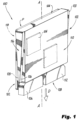
Fig. 1 is a schematic perspective view of an embodiment of an assembly constructed in accordance with the present disclosure, showing the circuit card assembly (CCA), connectors, and heatsink with wedge features; -
Fig. 2 is a perspective view of a portion of a chassis for an assembly ofFig. 1 , showing the rail features in an internal surface of the chassis; and -
Fig. 3 is an exploded perspective view of the assembly ofFig. 1 , showing the card or module with the CCA, connectors, and heatsink being inserted into the chassis. - Reference will now be made to the drawings wherein like reference numerals identify similar structural features or aspects of the subject disclosure. For purposes of explanation and illustration, and not limitation, a partial view of an embodiment of an electronic module assembly in accordance with the disclosure is shown in
Fig. 1 and is designated generally byreference character 100. Other embodiments of systems in accordance with the disclosure, or aspects thereof, are provided inFigs. 2-3 , as will be described. The systems and methods described herein can be used to improve heat sinking from heat generating components of circuit card assemblies (CCAs) relative to conventional wedge locks. - The
electronic module assembly 100 includes a circuit card assembly (CCA) 102 including heat generatingelectronic components 104. A first connector 106 is electrically connected to the heat generatingelectronic components 104. The connector is positioned at aconnection end 108 of theCCA 102. Aheatsink 110 is mounted to the CCA 102 and is connected in thermal communication with theelectronic components 104. At least oneadditional connector 112 is aligned with the first connector 106, e.g., for connecting independent functions or modules of theCCA 102 to anelectrical interface 138 of achassis 114, which shown and described below with reference toFig. 2-3 . Those skilled in the art will readily appreciate that any suitable number ofconnectors - With continued reference to
Fig. 1 , awedge feature 116 is defined along alateral edge 118 of the heatsink relative to the connector. Theheatsink 110 includes asecond wedge 120 feature defined along the oppositelateral edge 122 of the heatsink opposite thefirst wedge feature 116. Each wedge feature 116, 120 wedges down in a direction D from a top edge 124 (as oriented inFig. 1 ) of theCCA 102 opposite theconnection end 108 toward theconnectors 106, 112. Eachwedge lateral edge heatsink 110, although it can also extend less than the full length without departing from the scope of this disclosure. Eachwedge feature wedge surfaces 126, 128 (only labeled inFig. 1 forwedge feature 116, however they are similar for wedge feature 120). Eachwedge surface connectors 106, 112. Eachwedge surface CCA 102. - The
assembly 100 can include achassis 114, a portion of which is shown inFig. 2 . Arail feature 130 is defined on an inward facingsurface 132 of thechassis 114. Referring toFig. 3 , asecond rail feature 134 mirroring thefirst rail feature 130 is defined in the inward facing surface 136 of thechassis 114 opposite from thefirst rail 130. - With continued reference to
Fig. 3 , theconnectors electrical interface 138 in thechassis 114 by inserting the CCA/heat sink module 102/110 into thechassis 114 in the direction D along the insertion axis A. In doing so, the wedge features 116, 120 are engaged with therespective rail features heatsink 110 within thechassis 114. Opposedwedge surfaces 126, 128 (labeled inFig. 1 ) of the wedge features 116, 120 are engaged in thermal contact in their entirety withcorresponding surfaces 140, 142 (labeled inFig. 2 ) of therail features Fig. 1 ), through the heat sink and into thechassis 114. The wedge features 116, 120 andrail features connectors electrical interface 138 of the chassis 115 as the CCA 102 is inserted into thechassis 114. Theconnectors electrical interface 138, wedge features 116, 120, and rail features 130, 134 are configured to retain the card orassembly 148 of theCCA 102 in place within thechassis 114 without any other locking features, e.g. there are no traditional wedge locks required. - The
CCA 102 occupies a first bay 144 of thechassis 114. The chassis can includes any suitable number of additional bays, e.g. at the positions indicated byreference characters 146 inFig. 3 , which can include traditional wedge locks configured for retaining a wedge locking CCAs in thechassis 114, and/or a second set of rail features as disclosed herein configured for retaining asecond CCA 102 with corresponding wedge features 116, 120. The module orcard 148 of theCCA 102,heat sink 110, andconnectors bays 144, 146 of thechassis 114 can correspondingly be configured to receive CCA's complying with 3U, 6U, 9U, or VITA, or any other suitable envelope specifications. - Systems and methods as disclosed herein can provide potential benefits such as the following. In terms of technical performance relative to traditional systems, they can provide increased contact surface area at module/rail interface for improved thermal management. They can provide structural retention between module and rail without the use of additional components. Systems as disclosed herein can be applied across multiple adjacent modules in a single end assembly. In terms of cost and complexity, systems and methods as disclosed herein can reduce/eliminate wedgelock use and associated mounting hardware. They can also be applied as part of the normal machining/printing process of the heatsink and end assembly components, e.g. the wedge features and rail features can be machined or printed into the
heat sink 110 andchassis 114. - The methods and systems of the present disclosure, as described above and shown in the drawings, provide for improved heat sinking from heat generating components of circuit card assemblies (CCAs) relative to conventional wedge locks. While the apparatus and methods of the subject disclosure have been shown and described with reference to preferred embodiments, those skilled in the art will readily appreciate that changes and/or modifications may be made thereto without departing from the scope of the invention as defined by the claims.
Claims (15)
- An electronic module assembly comprising:a circuit card assembly, CCA, (102) including heat generating electronic components (104);a connector (106) electrically connected to the heat generating electronic components, wherein the connector is positioned at a connection end of the CCA; anda heatsink (110) mounted to the CCA and connected in thermal communication with the electronic components, wherein a wedge feature (116) is defined along a lateral edge (118) of the heatsink relative to the connector.
- The assembly as recited in claim 1, wherein the wedge feature wedges down in a direction from a top edge of the CCA toward the connector.
- The assembly as recited in claim 1 or 2, wherein the wedge feature is a first wedge feature (116), wherein the heatsink includes a second wedge feature (120) defined along a lateral edge (122) of the heatsink opposite the first wedge feature.
- The assembly as recited in any preceding claim, wherein the wedge feature extends along the full length of the lateral edge (118) of the heatsink.
- The assembly as recited in any preceding claim, wherein the wedge feature is defined between two wedge surfaces (126, 128), wherein each wedge surface is oblique relative to an insertion axis defined by the connector.
- The assembly as recited in any of claims 1 to 4, wherein the wedge feature is defined between two wedge surfaces, wherein each wedge surface is oblique relative to a plane defined by the CCA.
- The assembly as recited in any preceding claim, further comprising a chassis (114), wherein a rail feature (130) is defined on an inward facing surface of the chassis, and wherein the connector is connected to a corresponding electrical interface (138) in the chassis with the wedge feature engaged with the rail feature to house the CCA and heatsink within the chassis.
- The assembly as recited in claim 7, wherein opposed wedge surfaces of the wedge feature are engaged in thermal contact in their entirety with corresponding surfaces of the rail feature for sinking heat from the heat generating electronic components to the chassis.
- The assembly as recited in claim 8, wherein the wedge feature and rail feature are configured to guide the connector to connect with the electrical interface of the chassis as the CCA is inserted into the chassis.
- The assembly as recited in claim 9, wherein the connector, electrical interface, wedge feature, and rail feature are configured to retain the CCA in place within the chassis.
- The assembly as recited in claim 7, wherein the CCA occupies a first bay (144) of the chassis, wherein the chassis includes a second bay (146) with wedge locks configured for retaining a wedge locking CCA in the chassis.
- The assembly as recited in claim 7, wherein the CCA occupies a first bay of the chassis, wherein the chassis includes a second bay with a second rail feature (134) configured for retaining a second CCA with a corresponding wedge feature.
- The assembly as recited in claim 7, wherein the CCA occupies a bay of the chassis that is configured to receive CCA modules complying with one of 3U, 6U, 9U, and VITA-compliant module envelopes.
- The assembly as recited in claim 7, wherein the wedge feature is a first wedge feature (116) and the rail feature is a first rail feature (130), wherein the heatsink includes a second wedge feature (120) defined along a lateral edge of the heatsink opposite the first wedge feature, wherein the chassis includes a second rail feature (134) defined on an inward facing surface of the chassis opposite the first rail feature, and wherein the second wedge feature is engaged with the second rail feature.
- The assembly as recited in any preceding claim, wherein the connector is a first connector (108) and further comprising at least one additional connector (112) aligned with the first connector for connecting independent functions of the CCA to an electrical interface of a chassis.
Applications Claiming Priority (1)
| Application Number | Priority Date | Filing Date | Title |
|---|---|---|---|
| US17/673,992 US12075587B2 (en) | 2022-02-17 | 2022-02-17 | Heat transfer interfaces for circuit card assembly (CCA) modules |
Publications (1)
| Publication Number | Publication Date |
|---|---|
| EP4231793A1 true EP4231793A1 (en) | 2023-08-23 |
Family
ID=85278495
Family Applications (1)
| Application Number | Title | Priority Date | Filing Date |
|---|---|---|---|
| EP23157066.4A Pending EP4231793A1 (en) | 2022-02-17 | 2023-02-16 | Heat transfer interfaces for circuit card assembly (cca) modules |
Country Status (2)
| Country | Link |
|---|---|
| US (1) | US12075587B2 (en) |
| EP (1) | EP4231793A1 (en) |
Citations (4)
| Publication number | Priority date | Publication date | Assignee | Title |
|---|---|---|---|---|
| WO2009149640A1 (en) * | 2008-06-13 | 2009-12-17 | 华为技术有限公司 | Thermal transfer device |
| US20140133093A1 (en) * | 2012-11-15 | 2014-05-15 | International Business Machines Corporation | Cooling system for electronics |
| US20150230365A1 (en) * | 2014-02-07 | 2015-08-13 | Lockheed Martin Corporation | Fluid-flow-through cooling of circuit boards |
| US20210109574A1 (en) * | 2019-10-15 | 2021-04-15 | Hewlett Packard Enterprise Development Lp | Power supply dry disconnect liquid cooling |
Family Cites Families (20)
| Publication number | Priority date | Publication date | Assignee | Title |
|---|---|---|---|---|
| US4867235A (en) * | 1986-10-20 | 1989-09-19 | Westinghouse Electric Corp. | Composite heat transfer means |
| US5255738A (en) * | 1992-07-16 | 1993-10-26 | E-Systems, Inc. | Tapered thermal substrate for heat transfer applications and method for making same |
| US6141211A (en) * | 1998-06-29 | 2000-10-31 | Hewlett-Packard Company | Heat sink conduction between disk drive carrier and information storage enclosure |
| US6246582B1 (en) | 1998-12-30 | 2001-06-12 | Honeywell Inc. | Interchangeable stiffening frame with extended width wedgelock for use in a circuit card module |
| US20080130219A1 (en) * | 1999-05-11 | 2008-06-05 | Josef Rabinovitz | Enclosure for computer peripheral devices |
| US6665184B2 (en) | 2001-07-13 | 2003-12-16 | Lytron, Inc. | Tapered cold plate |
| US7180737B2 (en) * | 2004-12-20 | 2007-02-20 | Harris Corporation | Heat exchanger system for circuit card assemblies |
| US7483271B2 (en) | 2005-05-19 | 2009-01-27 | Bae Systems Information And Electronic Systems Integration Inc. | High density card retention device |
| US7719837B2 (en) * | 2005-08-22 | 2010-05-18 | Shan Ping Wu | Method and apparatus for cooling a blade server |
| US8223497B2 (en) * | 2009-09-10 | 2012-07-17 | Honeywell International Inc. | Thermal bridge extensions for a module-chassis interface |
| US8570744B2 (en) * | 2009-10-30 | 2013-10-29 | Hewlett-Packard Development Company, L.P. | Cold plate having blades that interleave with memory modules |
| WO2011053313A1 (en) | 2009-10-30 | 2011-05-05 | Hewlett-Packard Development Company, L.P. | Cooling memory modules using wedge-shaped heat spreaders in thermal contact with cold plate blades and memory modules |
| US8477498B2 (en) * | 2010-03-25 | 2013-07-02 | Curtiss-Wright Controls, Inc. | Conduction-cooled apparatus and methods of forming said apparatus |
| US8174826B2 (en) * | 2010-05-27 | 2012-05-08 | International Business Machines Corporation | Liquid cooling system for stackable modules in energy-efficient computing systems |
| US8446722B2 (en) * | 2010-09-10 | 2013-05-21 | Src, Inc. | Circuit board chassis and method including sidewall aperture and backplane insertion slots for side assembled backplane |
| US9414524B2 (en) * | 2013-09-11 | 2016-08-09 | Artesyn Embedded Computing, Inc. | Extended heat frame for printed circuit board |
| US9357670B2 (en) | 2014-02-18 | 2016-05-31 | Lockheed Martin Corporation | Efficient heat transfer from conduction-cooled circuit cards |
| US10034403B1 (en) | 2017-03-09 | 2018-07-24 | Advanced Cooling Technologies, Inc. | Card retainer device |
| CN108430188B (en) | 2018-02-12 | 2020-03-13 | 西南电子技术研究所(中国电子科技集团公司第十研究所) | Wedge-shaped locking device for high-efficiency heat dissipation of electronic module plug-in |
| JP6906709B2 (en) * | 2018-09-14 | 2021-07-21 | 三菱電機株式会社 | Power converter |
-
2022
- 2022-02-17 US US17/673,992 patent/US12075587B2/en active Active
-
2023
- 2023-02-16 EP EP23157066.4A patent/EP4231793A1/en active Pending
Patent Citations (4)
| Publication number | Priority date | Publication date | Assignee | Title |
|---|---|---|---|---|
| WO2009149640A1 (en) * | 2008-06-13 | 2009-12-17 | 华为技术有限公司 | Thermal transfer device |
| US20140133093A1 (en) * | 2012-11-15 | 2014-05-15 | International Business Machines Corporation | Cooling system for electronics |
| US20150230365A1 (en) * | 2014-02-07 | 2015-08-13 | Lockheed Martin Corporation | Fluid-flow-through cooling of circuit boards |
| US20210109574A1 (en) * | 2019-10-15 | 2021-04-15 | Hewlett Packard Enterprise Development Lp | Power supply dry disconnect liquid cooling |
Also Published As
| Publication number | Publication date |
|---|---|
| US20230262917A1 (en) | 2023-08-17 |
| US12075587B2 (en) | 2024-08-27 |
Similar Documents
| Publication | Publication Date | Title |
|---|---|---|
| US7101188B1 (en) | Electrical edge connector adaptor | |
| US7172432B2 (en) | Stacked multiple connection module | |
| US6935868B1 (en) | Adjustable-width, dual-connector card module | |
| US6272016B1 (en) | Avionics rack with external electronics module | |
| US5947753A (en) | High density connector arrangement for a circuit board module | |
| US6672878B2 (en) | Actuatable connector system | |
| US9325086B2 (en) | Doubling available printed wiring card edge for high speed interconnect in electronic packaging applications | |
| US3660803A (en) | Electrical connectors | |
| US6064575A (en) | Circuit module assembly | |
| EP3103316B1 (en) | Fluid-flow-through cooling of circuit boards | |
| CN1960063B (en) | vertical docking connector | |
| CN101689718B (en) | Coplanar angle mate straddle mount connector | |
| US5892658A (en) | VME eurocard triple printed wiring board single slot module assembly | |
| EP0745279A1 (en) | Shielded circuit board connector module | |
| US6762362B1 (en) | Apparatus and method for connecting a power supply to multiple backplanes within an electronic equipment cabinet | |
| US11956927B2 (en) | Case, fan module and fan frame | |
| CN110794930A (en) | Server, floating connector and system | |
| US6449163B1 (en) | Inboard retention system for processor enclosure assemblies with substrate alignment | |
| KR20120053083A (en) | Electronic device | |
| TW202404217A (en) | Cable bracket for stacked hbas with bracket-mounted connectors | |
| US20030227755A1 (en) | Electronics assembly | |
| EP3674842A1 (en) | Multi-card subsystem for embedded computing systems | |
| EP4271155A1 (en) | Heat transfer interfaces for circuit card assembly (cca) modules | |
| US12075587B2 (en) | Heat transfer interfaces for circuit card assembly (CCA) modules | |
| US6208527B1 (en) | Retention mechanism assembly for processor cartridges with captured screw fasteners |
Legal Events
| Date | Code | Title | Description |
|---|---|---|---|
| PUAI | Public reference made under article 153(3) epc to a published international application that has entered the european phase |
Free format text: ORIGINAL CODE: 0009012 |
|
| STAA | Information on the status of an ep patent application or granted ep patent |
Free format text: STATUS: THE APPLICATION HAS BEEN PUBLISHED |
|
| AK | Designated contracting states |
Kind code of ref document: A1 Designated state(s): AL AT BE BG CH CY CZ DE DK EE ES FI FR GB GR HR HU IE IS IT LI LT LU LV MC ME MK MT NL NO PL PT RO RS SE SI SK SM TR |
|
| STAA | Information on the status of an ep patent application or granted ep patent |
Free format text: STATUS: REQUEST FOR EXAMINATION WAS MADE |
|
| 17P | Request for examination filed |
Effective date: 20240223 |
|
| RBV | Designated contracting states (corrected) |
Designated state(s): AL AT BE BG CH CY CZ DE DK EE ES FI FR GB GR HR HU IE IS IT LI LT LU LV MC ME MK MT NL NO PL PT RO RS SE SI SK SM TR |