EP4231761A1 - Downlink lbt method and apparatus, device, and storage medium - Google Patents
Downlink lbt method and apparatus, device, and storage medium Download PDFInfo
- Publication number
- EP4231761A1 EP4231761A1 EP21882011.6A EP21882011A EP4231761A1 EP 4231761 A1 EP4231761 A1 EP 4231761A1 EP 21882011 A EP21882011 A EP 21882011A EP 4231761 A1 EP4231761 A1 EP 4231761A1
- Authority
- EP
- European Patent Office
- Prior art keywords
- energy
- time window
- channel
- detection time
- monitoring period
- Prior art date
- Legal status (The legal status is an assumption and is not a legal conclusion. Google has not performed a legal analysis and makes no representation as to the accuracy of the status listed.)
- Pending
Links
Images


Classifications
-
- H—ELECTRICITY
- H04—ELECTRIC COMMUNICATION TECHNIQUE
- H04W—WIRELESS COMMUNICATION NETWORKS
- H04W74/00—Wireless channel access
- H04W74/08—Non-scheduled access, e.g. ALOHA
- H04W74/0808—Non-scheduled access, e.g. ALOHA using carrier sensing, e.g. carrier sense multiple access [CSMA]
Definitions
- the present application relates to the field of communication technologies and, in particular, to a method and an apparatus for downlink listen before talk (Listen Before Talk, abbreviated as LBT), a device and a storage medium.
- LBT downlink listen before talk
- Uplink Uplink
- Downlink Downlink
- a network device and a terminal need to perform channel access by means of an LBT method, i.e., firstly determining a channel state by detecting channel energy, and then further determining whether data transmission can be performed. If the detected channel energy is inaccurate, the channel state may be inaccurate, thereby reducing spectrum utilization.
- the present application provides a method and an apparatus for downlink LBT, a device, and a storage medium, so as to improve accuracy of detection on a channel state and improve spectrum utilization.
- the present application provides a method for downlink LBT, including:
- the determining the channel state within the monitoring period according to the channel energy and the uplink transmission energy includes: determining the channel state within the monitoring period according to a difference between the channel energy and the uplink transmission energy.
- the monitoring period includes at least one detection time window and a calculation time window; the detecting the channel energy and the uplink transmission energy within the monitoring period includes: detecting respective channel energy within each detection time window, and calculating the uplink transmission energy within the calculation time window.
- the monitoring period includes a plurality of detection time windows
- the calculation time window is between any two detection time windows of the plurality of detection time windows.
- the calculation time window is after the at least one detection time window.
- the determining the channel state within the monitoring period according to the difference between the channel energy and the uplink transmission energy includes:
- the present application provides an apparatus for downlink LBT, including:
- the determining module is configured to determine the channel state within the monitoring period according to a difference between the channel energy and the uplink transmission energy.
- the monitoring period includes at least one detection time window and a calculation time window; the detecting module is configured to detect respective channel energy within each detection time window, and calculate the uplink transmission energy within the calculation time window.
- the monitoring period includes a plurality of detection time windows
- the calculation time window is between any two detection time windows of the plurality of detection time windows.
- the calculation time window is after the at least one detection time window.
- the determining module is configured to: determine a channel state within each detection time window according to a respective difference between the channel energy within each detection time window and the uplink transmission energy; and determine the channel state within the monitoring period according to the channel state within each detection time window.
- the present application provides an electronic device, including: a memory, a processor, and a transceiver;
- the present application provides a computer-readable storage medium on which a computer program is stored.
- the computer program is executed by a processor, the method according to the first aspect is implemented.
- the present application provides a method and an apparatus for downlink LBT, a device, and a storage medium.
- uplink transmission energy is further determined, and this part of uplink transmission energy is removed from total channel energy, so that a channel state can be evaluated based on a more accurate energy value, and spectrum utilization is improved.
- an application scenario of full-duplex communication may be a hotspot with discontinuous coverage, such as a femtocell or WIFI; or a scenario with continuous coverage, such as a homogeneous network scenario or a heterogeneous network scenario, or a device-to-device (Device-to-Device, abbreviated as D2D) short-distance communication scenario, which is not limited in the present application.
- D2D device-to-device
- the terminal in the embodiments of the present application may also be referred to as a terminal equipment (Terminal Equipment), a subscriber unit (Subscriber Unit), a subscriber station (Subscriber Station), a mobile station (Mobile Station), a mobile station (Mobile Station), a remote station (Remote Station), an access point (Access Point), a remote terminal (Remote Terminal), an access terminal (Access Terminal), a user terminal (User Terminal), a user agent (User Agent), or a user equipment (User Equipment), which is not limited herein.
- the UE in the embodiments of the present application may adopt half-duplex or full-duplex.
- the network device in the embodiments of the present application refers to a communication network device providing a communication service for a terminal, including a base station (base station, abbreviated as BS) in a radio access network, further including a base station controller in the radio access network, and further including a device at the core network side.
- BS base station
- BS controller base station controller
- the base station may also be referred to as a base station device, and is an apparatus deployed in a radio access network (RAN) to provide a wireless communication function.
- a device providing a base station function in a 4G network includes an evolved node B (evolved NodeB, abbreviated as eNB), a device gNB providing a base station function in 5G new radio (New Radio, abbreviated as NR), and a next generation evolved node B (ng-eNB).
- eNB evolved NodeB
- gNB 5G new radio
- ng-eNB next generation evolved node B
- the gNB and the terminal communicate with each other by using NR technologies
- the ng-eNB and the terminal communicate with each other by using evolved universal terrestrial radio access (Evolved Universal Terrestrial Radio Access, abbreviated as E-UTRA) technologies
- E-UTRA evolved universal terrestrial radio access
- both the gNB and the ng-eNB may be connected to the 5G core network.
- the base station in the embodiments of the present application further includes a device providing a base station function in a future new communication system, and the like.
- the base station in the embodiments of the present application may be a full-duplex base station, and may serve uplink and downlink of different UEs on the same time-frequency resource, for example, uplink of UE-1 and downlink of UE-2; or serve uplink and downlink of the same UE.
- a base station or a terminal determines whether a channel state is idle or busy by detecting channel energy.
- a problem that may occur in this case is that, in a full-duplex system, when downlink LBT is performed, an uplink signal for paired transmission may exist on the same time-frequency resource, and therefore the channel energy obtained when performing channel energy detection includes this part of uplink transmission energy.
- only downlink transmission energy needs to be considered when performing downlink LBT.
- the channel energy detected in a downlink LBT process is not accurate, which results in that the channel state determined based on the channel energy is not accurate, thereby affecting downlink transmission.
- channel energy detected in the downlink LBT process is excessively high, so that it is determined that a channel state is busy and downlink transmission cannot be performed, thereby reducing spectrum utilization.
- the present application provides a method for downlink LBT, which improves a method for determining a channel state.
- uplink transmission energy is further determined, and this part of uplink transmission energy is removed from total channel energy, so that a channel state can be evaluated based on a more accurate energy value, and the spectrum utilization is improved.
- the method for downlink LBT provided in the present application is described below with reference to embodiments.
- a channel presented in the present application may be understood as a time-frequency resource area, and a terminal or a base station may perform LBT monitoring in the time-frequency resource area.
- FIG. 2 is a schematic flowchart of a method for downlink LBT according to an embodiment of the present application.
- An execution subject of the method may be a network device or a terminal, and an example that the network device is a base station is used for description. As shown in FIG. 2 , the method includes the following.
- S203 perform downlink data transmission when the channel state is an idle state.
- channel energy may be detected by using one or more detection time windows within the monitoring period, so as to determine a channel state.
- the base station may also determine the uplink transmission energy according to the detected channel energy.
- the base station removes the uplink transmission energy from the detected channel energy, i.e., determines a channel state within the monitoring period according to a difference between the channel energy and the uplink transmission energy, so that the channel state determined based on the channel energy is more accurate, thereby guaranteeing the downlink transmission, and improving the spectrum utilization.
- the base station calculates energy of corresponding uplink signals on a time-frequency resource for performing LBT, removes the energy of the uplink signals from an energy detection result of a corresponding LBT, and uses the calculated energy detection result to determine whether the time-frequency resource monitored in the LBT process is idle or busy.
- the monitoring period includes at least one detection time window and a calculation time window.
- the base station detects respective channel energy within each detection time window, and calculates the uplink transmission energy within the calculation time window, so as to determine a channel state within each detection time window according to a respective difference between the channel energy within each detection time window and the uplink transmission energy; and determine the channel state within the monitoring period according to the channel state within each detection time window.
- the quantity of detection time windows included in the monitoring period may vary with different LBT methods. If the monitoring period includes a plurality of detection time windows, the calculation time window may be between any two detection time windows of the plurality of detection time windows. Or, when the monitoring period includes one or more detection time windows, the calculation time window may be after the one or more detection time windows.
- Type 1 CAT4 LBT
- CW min,p ⁇ CW p ⁇ CW max,p is a contention window, values of CW min,p and CW max,p are determined before step 1).
- m p , CW min , p and CW max,p are determined based on a channel access priority p associated with base station transmission.
- a calculation time window D is added between a plurality of detection time windows, or a calculation time window D is added after a plurality of detection time windows. Uplink transmission energy is calculated within the calculation time window D, and the uplink transmission energy is subtracted from channel energy within each detection time window, to determine a channel state within each detection time window.
- the calculation time window D being after a first T sl is taken as an example, after performing channel energy detection of an additional detection slot T sl for the first time in step 3), the base station, next, calculates the uplink transmission energy within the calculation time window D, and then subtracts the uplink transmission energy from the channel energy within the first T sl to determine that a channel state of the first T sl is idle or busy, and continues the foregoing loop in step 3) according to the channel state of the first T sl .
- the uplink transmission energy is subtracted from the detected channel energy, so as to determine the channel state within each T sl or T f .
- N 0, it is determined that the channel state within the monitoring period is idle, and the downlink transmission can be performed.
- the calculation time window D is after the first T sl is taken as an example for description, and in actual applications, the calculation time window D may be set after any T sl or T f .
- a specific position of the time window D may be determined in a predefined manner, or may be indicated by the base station through higher-layer signaling or DCI.
- a calculation time window D is added between T f and the subsequent detection slot of 9 us. Uplink transmission energy is calculated within the calculation time window D. As shown in FIG.
- a calculation time window D is added after T f and the subsequent detection slot of 9 us, and uplink transmission energy is calculated within the calculation time window D.
- T f includes a detection slot that occurs within the last 9 us of T f .
- Type 3 LBT suitable for FR2
- an LBT process suitable for FR2 includes a plurality of detection time windows, and each detection time window is 8 us, 5 us, or an additional delay duration.
- the additional delay duration may be 5 us, which is not limited in the embodiment of the present application.
- a calculation time window D is added between a plurality of detection time windows, or a calculation time window D is added after a plurality of detection time windows. Uplink transmission energy is calculated within the calculation time window D, and the uplink transmission energy is subtracted from channel energy within each detection time window, to determine a channel state within each detection time window.
- the calculation time window D being after a first detection time window of 8 us is taken as an example, after performing channel energy detection with a duration of 8 us in the above step 1), the base station, next, calculates the uplink transmission energy within the calculation time window D, and then subtracts the uplink transmission energy from the channel energy within 8 us to determine that a channel state within the first detection time window of 8 us is idle or busy, and continues the foregoing loop according to the channel state within the first detection time window of 8 us.
- the uplink transmission energy is subtracted from the detected channel energy to determine a channel state within each detection time window.
- N 0, it may be determined that the channel state within the monitoring period is idle, and downlink transmission can be performed.
- calculation time window D being after the first detection time window of 8 us is taken as an example for description, and in actual applications, the calculation time window D may be set after other detection time windows.
- FIG. 8 is a schematic structural diagram of an apparatus for downlink LBT according to an embodiment of the present application.
- the apparatus 80 for downlink LBT includes:
- the determining module 802 is configured to determine the channel state within the monitoring period according to a difference between the channel energy and the uplink transmission energy.
- the monitoring period includes at least one detection time window and a calculation time window; the detecting module 801 is configured to detect respective channel energy within each detection time window, and calculate uplink transmission energy within the calculation time window.
- the monitoring period includes a plurality of detection time windows
- the calculation time window is between any two detection time windows of the plurality of detection time windows.
- the calculation time window is after the at least one detection time window.
- the determining module 802 is configured to: determine a channel state within each detection time window according to a respective difference between the channel energy within each detection time window and the uplink transmission energy; and determine the channel state within the monitoring period according to the channel state within each detection time window.
- the apparatus provided in the embodiments of the present application can be used for executing the method for downlink LBT in the described method embodiments, which is implemented using similar principles and produce similar calculation effects. Details will not be described again here.
- FIG. 9 is a schematic structural diagram of an electronic device according to an embodiment of the present application.
- the electronic device 90 includes: a memory 91, a processor 92, and a transceiver 93, where the memory 91 is in communication with the processor 92.
- the memory 91, the processor 92, and the transceiver 93 may communicate by using a communication bus 94.
- the memory 91 is configured to store a computer program, and the processor 92 executes the computer program to implement the foregoing method for downlink LBT.
- the electronic device 90 may be a network device or a terminal.
- the foregoing processor may be a central processing unit (Central Processing Unit, CPU), and may also be other general processor, a digital signal processor (Digital Signal Processor, DSP), an application specific integrated circuit (Application Specific Integrated Circuit, ASIC), and the like.
- the general processor may be a microprocessor, or the processor may also be any conventional processor.
- the steps may be directly implemented by a hardware processor or implemented by a combination of hardware and software modules in the processor.
- An embodiment of the present application further provides a computer-readable storage medium on which a computer program is stored.
- the program is executed by a processor, the method according to any of the described method embodiments is implemented.
- the foregoing memory includes a read-only memory (read-only memory, ROM), a RAM, a flash memory, a hard disk, a solid-state drive, a magnetic tape (magnetic tape), a floppy disk (floppy disk), an optical disc (optical disc), and any combination thereof.
- These computer program instructions may be provided to a processing unit of a general computer, a dedicated computer, an embedded processor or other programmable data processing device to produce a machine, so that the instructions that are executed by the processing unit of the computer or other programmable data processing device generate an apparatus for implementing functions specified in one or more flows in the flowcharts and/or one or more blocks in the block diagrams.
- These computer program instructions may also be stored in a computer-readable memory capable of guiding a computer or other programmable data processing device to work in a specific manner, so that the instructions stored in the computer-readable memory generate a manufactured product including an instruction apparatus, and the instruction apparatus implements functions specified in one or more flows in the flowcharts and/or one or more blocks in the block diagrams.
Landscapes
- Engineering & Computer Science (AREA)
- Computer Networks & Wireless Communication (AREA)
- Signal Processing (AREA)
- Mobile Radio Communication Systems (AREA)
Abstract
Description
- This application claims priority to
Chinese Patent Application No. 202011120000.7, filed with China National Intellectual Property Administration on October 19, 2020 - The present application relates to the field of communication technologies and, in particular, to a method and an apparatus for downlink listen before talk (Listen Before Talk, abbreviated as LBT), a device and a storage medium.
- In future communication systems, with the demand for higher data rates, the demand for spectrum resources is also explosively growing. By means of full-duplex communication technologies, uplink (Uplink) transmission and downlink (Downlink) transmission can be simultaneously performed on the same time-frequency resource, thereby greatly improving utilization of the spectrum resources.
- In full-duplex communication, not only a licensed spectrum can be used, but also an unlicensed spectrum can be used. When the unlicensed spectrum is used, a network device and a terminal need to perform channel access by means of an LBT method, i.e., firstly determining a channel state by detecting channel energy, and then further determining whether data transmission can be performed. If the detected channel energy is inaccurate, the channel state may be inaccurate, thereby reducing spectrum utilization.
- The present application provides a method and an apparatus for downlink LBT, a device, and a storage medium, so as to improve accuracy of detection on a channel state and improve spectrum utilization.
- In a first aspect, the present application provides a method for downlink LBT, including:
- detecting channel energy and uplink transmission energy within a monitoring period;
- determining a channel state within the monitoring period according to the channel energy and the uplink transmission energy;
- performing downlink data transmission when the channel state is an idle state.
- In a feasible implementation manner, the determining the channel state within the monitoring period according to the channel energy and the uplink transmission energy includes:
determining the channel state within the monitoring period according to a difference between the channel energy and the uplink transmission energy. - In a feasible implementation manner, the monitoring period includes at least one detection time window and a calculation time window;
the detecting the channel energy and the uplink transmission energy within the monitoring period includes:
detecting respective channel energy within each detection time window, and calculating the uplink transmission energy within the calculation time window. - In a feasible implementation manner, the monitoring period includes a plurality of detection time windows, and the calculation time window is between any two detection time windows of the plurality of detection time windows.
- In a feasible implementation manner, the calculation time window is after the at least one detection time window.
- In a feasible implementation manner, the determining the channel state within the monitoring period according to the difference between the channel energy and the uplink transmission energy includes:
- determining a channel state within each detection time window according to a respective difference between the channel energy within each detection time window and the uplink transmission energy;
- determining the channel state within the monitoring period according to the channel state within each detection time window.
- In a second aspect, the present application provides an apparatus for downlink LBT, including:
- a detecting module, configured to detect channel energy and uplink transmission energy within a monitoring period;
- a determining module, configured to determine a channel state within the monitoring period according to the channel energy and the uplink transmission energy;
- a transmitting module, configured to perform downlink data transmission when the channel state is an idle state.
- In a feasible implementation manner, the determining module is configured to determine the channel state within the monitoring period according to a difference between the channel energy and the uplink transmission energy.
- In a feasible implementation manner, the monitoring period includes at least one detection time window and a calculation time window;
the detecting module is configured to detect respective channel energy within each detection time window, and calculate the uplink transmission energy within the calculation time window. - In a feasible implementation manner, the monitoring period includes a plurality of detection time windows, and the calculation time window is between any two detection time windows of the plurality of detection time windows.
- In a possible implementation manner, the calculation time window is after the at least one detection time window.
- In a feasible implementation manner, the determining module is configured to: determine a channel state within each detection time window according to a respective difference between the channel energy within each detection time window and the uplink transmission energy; and determine the channel state within the monitoring period according to the channel state within each detection time window.
- In a third aspect, the present application provides an electronic device, including: a memory, a processor, and a transceiver;
- where the memory is configured to store a computer program;
- the processor is configured to implement the method according to the first aspect when the computer program is executed.
- In a fourth aspect, the present application provides a computer-readable storage medium on which a computer program is stored. When the computer program is executed by a processor, the method according to the first aspect is implemented.
- The present application provides a method and an apparatus for downlink LBT, a device, and a storage medium. Within a monitoring period, in addition to detecting channel energy, uplink transmission energy is further determined, and this part of uplink transmission energy is removed from total channel energy, so that a channel state can be evaluated based on a more accurate energy value, and spectrum utilization is improved.
- To describe technical solutions in embodiments of the present application or in the prior art more clearly, the accompanying drawings required for describing the embodiments or the prior art will be briefly introduced hereunder. Apparently, the accompanying drawings in the following description show some embodiments of the present application. For a person of ordinary skill in the art, other drawings may also be obtained according to these drawings without creative efforts.
-
FIG. 1 is an application scenario diagram of full-duplex communication. -
FIG. 2 is a schematic flowchart of a method for downlink LBT according to an embodiment of the present application. -
FIG. 3 is a schematic diagram of a monitoring period according to an embodiment of the present application. -
FIG. 4 is a schematic diagram of a monitoring period according to an embodiment of the present application. -
FIG. 5 is a schematic diagram of a monitoring period according to an embodiment of the present application. -
FIG. 6 is a schematic diagram of a monitoring period according to an embodiment of the present application. -
FIG. 7 is a schematic diagram of a monitoring period according to an embodiment of the present application. -
FIG. 8 is a schematic structural diagram of an apparatus for downlink LBT according to an embodiment of the present application. -
FIG 9 is a schematic structural diagram of an electronic device according to an embodiment of the present application. - To make objectives, technical solutions, and advantages of embodiments of the present application clearer, the technical solutions in the embodiments of the present application will be described hereunder clearly and comprehensively with reference to the accompanying drawings in the embodiments of the present application. Apparently, the described embodiments are intended for merely a part rather than all of the embodiments of the present application. All other embodiments obtained by a person of ordinary skill in the art based on the embodiments of the present application without creative efforts shall fall within the protection scope of the present application.
- The method for downlink LBT provided in the present application is applied to a scenario of full-duplex communication. Illustratively, as shown in
FIG. 1 , an application scenario of full-duplex communication may be a hotspot with discontinuous coverage, such as a femtocell or WIFI; or a scenario with continuous coverage, such as a homogeneous network scenario or a heterogeneous network scenario, or a device-to-device (Device-to-Device, abbreviated as D2D) short-distance communication scenario, which is not limited in the present application. - The terminal in the embodiments of the present application may also be referred to as a terminal equipment (Terminal Equipment), a subscriber unit (Subscriber Unit), a subscriber station (Subscriber Station), a mobile station (Mobile Station), a mobile station (Mobile Station), a remote station (Remote Station), an access point (Access Point), a remote terminal (Remote Terminal), an access terminal (Access Terminal), a user terminal (User Terminal), a user agent (User Agent), or a user equipment (User Equipment), which is not limited herein. The UE in the embodiments of the present application may adopt half-duplex or full-duplex.
- The network device in the embodiments of the present application refers to a communication network device providing a communication service for a terminal, including a base station (base station, abbreviated as BS) in a radio access network, further including a base station controller in the radio access network, and further including a device at the core network side.
- The base station may also be referred to as a base station device, and is an apparatus deployed in a radio access network (RAN) to provide a wireless communication function. For example, a device providing a base station function in a 4G network includes an evolved node B (evolved NodeB, abbreviated as eNB), a device gNB providing a base station function in 5G new radio (New Radio, abbreviated as NR), and a next generation evolved node B (ng-eNB). The gNB and the terminal communicate with each other by using NR technologies, the ng-eNB and the terminal communicate with each other by using evolved universal terrestrial radio access (Evolved Universal Terrestrial Radio Access, abbreviated as E-UTRA) technologies, both the gNB and the ng-eNB may be connected to the 5G core network. The base station in the embodiments of the present application further includes a device providing a base station function in a future new communication system, and the like. The base station in the embodiments of the present application may be a full-duplex base station, and may serve uplink and downlink of different UEs on the same time-frequency resource, for example, uplink of UE-1 and downlink of UE-2; or serve uplink and downlink of the same UE.
- In the related art, in the full-duplex communication scenario, there may be various methods for performing LBT when a channel is accessed on an unlicensed spectrum, including CAT4 LBT, One Shot LBT, and LBT suitable for FR2. In the various LBT methods, a base station or a terminal determines whether a channel state is idle or busy by detecting channel energy. A problem that may occur in this case is that, in a full-duplex system, when downlink LBT is performed, an uplink signal for paired transmission may exist on the same time-frequency resource, and therefore the channel energy obtained when performing channel energy detection includes this part of uplink transmission energy. However, in practice, only downlink transmission energy needs to be considered when performing downlink LBT. Therefore, in the current method, the channel energy detected in a downlink LBT process is not accurate, which results in that the channel state determined based on the channel energy is not accurate, thereby affecting downlink transmission. For example, due to existence of uplink transmission, channel energy detected in the downlink LBT process is excessively high, so that it is determined that a channel state is busy and downlink transmission cannot be performed, thereby reducing spectrum utilization.
- To this end, the present application provides a method for downlink LBT, which improves a method for determining a channel state. Within a monitoring period, in addition to detecting channel energy, uplink transmission energy is further determined, and this part of uplink transmission energy is removed from total channel energy, so that a channel state can be evaluated based on a more accurate energy value, and the spectrum utilization is improved. The method for downlink LBT provided in the present application is described below with reference to embodiments. A channel presented in the present application may be understood as a time-frequency resource area, and a terminal or a base station may perform LBT monitoring in the time-frequency resource area.
-
FIG. 2 is a schematic flowchart of a method for downlink LBT according to an embodiment of the present application. An execution subject of the method may be a network device or a terminal, and an example that the network device is a base station is used for description. As shown inFIG. 2 , the method includes the following. - S201, detect channel energy and uplink transmission energy within a monitoring period.
- S202, determine a channel state within the monitoring period according to the channel energy and the uplink transmission energy.
- S203, perform downlink data transmission when the channel state is an idle state.
- When the base station performs downlink LBT, channel energy may be detected by using one or more detection time windows within the monitoring period, so as to determine a channel state. In this embodiment, besides detecting the channel energy within the monitoring period, the base station may also determine the uplink transmission energy according to the detected channel energy.
- The base station removes the uplink transmission energy from the detected channel energy, i.e., determines a channel state within the monitoring period according to a difference between the channel energy and the uplink transmission energy, so that the channel state determined based on the channel energy is more accurate, thereby guaranteeing the downlink transmission, and improving the spectrum utilization.
- Illustratively, the base station calculates energy of corresponding uplink signals on a time-frequency resource for performing LBT, removes the energy of the uplink signals from an energy detection result of a corresponding LBT, and uses the calculated energy detection result to determine whether the time-frequency resource monitored in the LBT process is idle or busy.
- Specifically, the monitoring period includes at least one detection time window and a calculation time window. The base station detects respective channel energy within each detection time window, and calculates the uplink transmission energy within the calculation time window, so as to determine a channel state within each detection time window according to a respective difference between the channel energy within each detection time window and the uplink transmission energy; and determine the channel state within the monitoring period according to the channel state within each detection time window.
- The quantity of detection time windows included in the monitoring period may vary with different LBT methods. If the monitoring period includes a plurality of detection time windows, the calculation time window may be between any two detection time windows of the plurality of detection time windows. Or, when the monitoring period includes one or more detection time windows, the calculation time window may be after the one or more detection time windows.
- On the basis of the method for downlink LBT provided in the present application, CAT4 LBT, One Shot LBT and LBT suitable for FR2 in the related art are respectively improved, which will be described in detail below.
-
- 1) Set N = Ninit, where Ninit is a random number distributed between 0 and CWp with a uniform probability, and then execute step 4).
- 2) If N > 0 and the base station selects a decrement counter, then set N = N - 1.
- 3) Detect a channel within an additional detection slot Tsl , and if the channel within the additional detection slot Tsl is idle, execute step 4); otherwise, execute step 5).
- 4) If N = 0, then stop; otherwise, execute step 2).
- 5) Detect the channel until a busy detection slot Tsl is detected within one additional delay duration Td or all detection slots Tsl within the additional delay duration Td are detected as idle.
- 6) If the channel is detected as idle in all detection slots Tsl within the additional delay duration Td , turn to step 4); otherwise, execute step 5).
- In the described steps, the delay duration Td includes a duration Tf = 16us and mp successive detection slots Tsl thereafter, and Tf includes a detection slot Tsl at the beginning of Tf.
- CWmin,p ≤ CWp ≤ CWmax,p is a contention window, values of CWmin,p and CWmax,p are determined before step 1).
- mp , CWmin,p and CWmax,p are determined based on a channel access priority p associated with base station transmission.
- It can be seen that the process of CAT4 LBT includes a plurality of detection time windows, and each detection time window is Tf = 16us or a detection slot Tsl . The described steps 1) to 6) are performed cyclically according to a channel state in each detection time window, and until N = 0 , it is determined that downlink transmission may be performed.
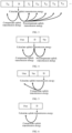
- In order to ensure accuracy of the channel state within each detection time window, according to the method in the embodiments of the present application, a calculation time window D is added between a plurality of detection time windows, or a calculation time window D is added after a plurality of detection time windows. Uplink transmission energy is calculated within the calculation time window D, and the uplink transmission energy is subtracted from channel energy within each detection time window, to determine a channel state within each detection time window.
- As shown in
FIG. 3 , the calculation time window D being after a first Tsl is taken as an example, after performing channel energy detection of an additional detection slot Tsl for the first time in step 3), the base station, next, calculates the uplink transmission energy within the calculation time window D, and then subtracts the uplink transmission energy from the channel energy within the first Tsl to determine that a channel state of the first Tsl is idle or busy, and continues the foregoing loop in step 3) according to the channel state of the first Tsl . In each subsequent detection slot of Tsl or Tf , the uplink transmission energy is subtracted from the detected channel energy, so as to determine the channel state within each Tsl or Tf . Thus, an execution step of the loop is determined, and until N = 0, it is determined that the channel state within the monitoring period is idle, and the downlink transmission can be performed. - It should be noted that, in
FIG. 3 , that the calculation time window D is after the first Tsl is taken as an example for description, and in actual applications, the calculation time window D may be set after any Tsl or Tf. A specific position of the time window D may be determined in a predefined manner, or may be indicated by the base station through higher-layer signaling or DCI. - The base station sends downlink transmission after detecting that a channel is idle for at least a detection interval Tshort_dl = 25us , where Tshort_dl includes a duration Tf = 16us and a detection slot of 9 us thereafter, and Tf includes a detection slot of 9 us at the beginning of Tf.
- It can be seen that in this manner, the base station performs channel detection once within a duration of Tf = 16us, and performs channel detection once again within a subsequent detection slot of 9 us, that is, a detection time window of Tf = 16us and a detection time window with a detection slot of 9 us are included in the monitoring period. In order to ensure accuracy of the channel state detected each time, according to the method of the embodiments of the present application, a calculation time window D is added between Tf and the subsequent detection slot of 9 us. Uplink transmission energy is calculated within the calculation time window D. As shown in
FIG. 4 , after performing channel energy detection once within the time of a duration Tf = 16us, the base station next calculates the uplink transmission energy within the calculation time window D, then determines a channel state within Tf = 16us by subtracting the uplink transmission energy from the channel energy within Tf = 16us, and continues to perform channel energy detection once again within the subsequent detection slot of 9 us, and determines a channel state within the detection slot of 9 us by subtracting the uplink transmission energy from the channel energy within the detection slot of 9 us. If the two channel states detected within Tf = 16us and within the detection slot of 9 us are both idle, it may be determined that the channel state within the monitoring period is idle, and downlink transmission can be performed. - Or, as shown in
FIG. 5 , a calculation time window D is added after Tf and the subsequent detection slot of 9 us, and uplink transmission energy is calculated within the calculation time window D. The base station performs channel energy detection once within the duration Tf = 16us, and performs channel energy detection once again within the subsequent detection slot of 9 us, and then calculates the uplink transmission energy within the calculation time window D. Then, the uplink transmission energy is respectively subtracted from the channel energy within Tf = 16us and the channel energy within the detection slot of 9 us, and a channel state within Tf = 16us and a channel state within the detection slot of 9 us are determined. If the two detected channel states are both idle, it may be determined that the channel state within the monitoring period is idle, and downlink transmission can be performed. - The base station may send downlink transmission immediately after detecting that a channel is idle for a duration of Tf = 16us. Tf includes a detection slot that occurs within the last 9 us of Tf.
- It can be seen that, the base station performs channel detection once within the time of the duration Tf = 16us, that is, a detection time window of Tf = 16us is included in the monitoring period. In order to ensure accuracy of a channel state, according to the method of the embodiments of the present application, as shown in
FIG. 6 , a calculation time window D is added after Tf = 16us, and uplink transmission energy is calculated within the calculation time window D. The base station performs channel energy detection once within the time of the duration Tf = 16us, and then calculates the uplink transmission energy within the calculation time window D. Then the uplink transmission energy is subtracted from the channel energy within Tf = 16us to determine a channel state within Tf = 16us. If the channel states are both idle, then downlink transmission can be performed. -
- 1) A base station detects a duration of 8 us, and if a channel is idle, execute step 2).
- 2) Set N = Ninit, where Ninit is a random number distributed in [1,2,3,4,5] with an average probability.
- 3) If N > 0 and the base station selects a decrement counter, then set N = N - 1.
- 4) Detect a channel within an additional detection slot (5 us), and if the channel within the additional detection slot is idle, execute step 5); otherwise, execute step 6).
- 5) If N = 0, then stop; otherwise, execute step 3).
- 6) Detect the channel until a busy detection slot is detected within an additional delay duration or all detection slots within the additional delay duration are detected as idle.
- 7) If the channel is detected as idle in all detection slots within the additional delay duration, turn to step 5); otherwise, execute step 6).
- It can be seen that an LBT process suitable for FR2 includes a plurality of detection time windows, and each detection time window is 8 us, 5 us, or an additional delay duration. The additional delay duration may be 5 us, which is not limited in the embodiment of the present application. The foregoing steps 1) to 7) are performed cyclically according to the channel state in each detection time window, and until N = 0, it is determined that downlink transmission can be performed.
- In order to ensure accuracy of the channel state within each detection time window, according to the method in the embodiments of the present application, a calculation time window D is added between a plurality of detection time windows, or a calculation time window D is added after a plurality of detection time windows. Uplink transmission energy is calculated within the calculation time window D, and the uplink transmission energy is subtracted from channel energy within each detection time window, to determine a channel state within each detection time window.
- As shown in
FIG. 7 , the calculation time window D being after a first detection time window of 8 us is taken as an example, after performing channel energy detection with a duration of 8 us in the above step 1), the base station, next, calculates the uplink transmission energy within the calculation time window D, and then subtracts the uplink transmission energy from the channel energy within 8 us to determine that a channel state within the first detection time window of 8 us is idle or busy, and continues the foregoing loop according to the channel state within the first detection time window of 8 us. In each subsequent detection time window, the uplink transmission energy is subtracted from the detected channel energy to determine a channel state within each detection time window. Thus, an execution step of the loop is determined, and until N = 0, it may be determined that the channel state within the monitoring period is idle, and downlink transmission can be performed. - It should be noted that, in
FIG. 7 , the calculation time window D being after the first detection time window of 8 us is taken as an example for description, and in actual applications, the calculation time window D may be set after other detection time windows. - It can be seen from the above description of the improvements of CAT4 LBT, One Shot LBT, and LBT suitable for FR2 that, by adding a calculation time window for calculating uplink transmission energy within the monitoring period, the method provided in the embodiments of the present application ensures the accuracy of channel detection, thereby improving the spectrum utilization.
-
FIG. 8 is a schematic structural diagram of an apparatus for downlink LBT according to an embodiment of the present application. As shown inFIG. 8 , theapparatus 80 for downlink LBT includes: - a detecting
module 801, configured to detect channel energy and uplink transmission energy within a monitoring period; - a determining
module 802, configured to determine a channel state within the monitoring period according to the channel energy and the uplink transmission energy; - a
transmitting module 803, configured to perform downlink data transmission when the channel state is an idle state. - In a feasible implementation manner, the determining
module 802 is configured to determine the channel state within the monitoring period according to a difference between the channel energy and the uplink transmission energy. - In a feasible implementation manner, the monitoring period includes at least one detection time window and a calculation time window;
the detectingmodule 801 is configured to detect respective channel energy within each detection time window, and calculate uplink transmission energy within the calculation time window. - In a feasible implementation manner, the monitoring period includes a plurality of detection time windows, and the calculation time window is between any two detection time windows of the plurality of detection time windows.
- In a feasible implementation manner, the calculation time window is after the at least one detection time window.
- In a feasible implementation manner, the determining
module 802 is configured to: determine a channel state within each detection time window according to a respective difference between the channel energy within each detection time window and the uplink transmission energy; and determine the channel state within the monitoring period according to the channel state within each detection time window. - The apparatus provided in the embodiments of the present application can be used for executing the method for downlink LBT in the described method embodiments, which is implemented using similar principles and produce similar calculation effects. Details will not be described again here.
-
FIG. 9 is a schematic structural diagram of an electronic device according to an embodiment of the present application. As shown inFIG. 9 , theelectronic device 90 includes: amemory 91, aprocessor 92, and atransceiver 93, where thememory 91 is in communication with theprocessor 92. Illustratively, thememory 91, theprocessor 92, and thetransceiver 93 may communicate by using acommunication bus 94. Thememory 91 is configured to store a computer program, and theprocessor 92 executes the computer program to implement the foregoing method for downlink LBT. Theelectronic device 90 may be a network device or a terminal. - Optionally, the foregoing processor may be a central processing unit (Central Processing Unit, CPU), and may also be other general processor, a digital signal processor (Digital Signal Processor, DSP), an application specific integrated circuit (Application Specific Integrated Circuit, ASIC), and the like. The general processor may be a microprocessor, or the processor may also be any conventional processor. In combination with the steps in the method embodiments disclosed in the present application, the steps may be directly implemented by a hardware processor or implemented by a combination of hardware and software modules in the processor.
- An embodiment of the present application further provides a computer-readable storage medium on which a computer program is stored. When the program is executed by a processor, the method according to any of the described method embodiments is implemented.
- All or a part of the steps of the foregoing method embodiments may be implemented by a program instructing relevant hardware. The foregoing program may be stored in a readable memory, and when the program is running, the steps of the foregoing method embodiments are performed. The foregoing memory (storage medium) includes a read-only memory (read-only memory, ROM), a RAM, a flash memory, a hard disk, a solid-state drive, a magnetic tape (magnetic tape), a floppy disk (floppy disk), an optical disc (optical disc), and any combination thereof.
- The embodiments of the present application are described with reference to flowcharts and/or block diagrams of the method, device (system), and computer program product according to the embodiments of the present application. It should be understood that, each flow and/or block in the flowcharts and/or the block diagrams and a combination of flows and/or blocks in the flowcharts and/or the block diagrams can be implemented by computer program instructions. These computer program instructions may be provided to a processing unit of a general computer, a dedicated computer, an embedded processor or other programmable data processing device to produce a machine, so that the instructions that are executed by the processing unit of the computer or other programmable data processing device generate an apparatus for implementing functions specified in one or more flows in the flowcharts and/or one or more blocks in the block diagrams.
- These computer program instructions may also be stored in a computer-readable memory capable of guiding a computer or other programmable data processing device to work in a specific manner, so that the instructions stored in the computer-readable memory generate a manufactured product including an instruction apparatus, and the instruction apparatus implements functions specified in one or more flows in the flowcharts and/or one or more blocks in the block diagrams.
- These computer program instructions may also be loaded onto a computer or other programmable data processing devices, so that a series of operational steps are performed on the computer or other programmable devices to produce computer implemented processing. Thus, the instructions executed on the computer or other programmable devices provide steps for implementing functions specified in one or more flows in the flowcharts and/or one or more blocks in the block diagrams.
- Obviously, a person skilled in the art can make various modifications and variations to the embodiments of the present application without departing from the spirit and scope of the present application. As such, should these modifications and variations of the embodiments of the present application belong to the scope of the claims of the present application and their equivalents, the present application is intended to include these modifications and variations.
Claims (17)
- A method for downlink LBT, comprising:detecting channel energy and uplink transmission energy within a monitoring period;determining a channel state within the monitoring period according to the channel energy and the uplink transmission energy;performing downlink data transmission when the channel state is an idle state.
- The method according to claim 1, wherein the determining the channel state within the monitoring period according to the channel energy and the uplink transmission energy comprises:determining the channel state within the monitoring period according to a difference between the channel energy and the uplink transmission energy.
- The method according to claim 2, wherein the monitoring period comprises at least one detection time window and a calculation time window;
the detecting the channel energy and the uplink transmission energy within the monitoring period comprises:
detecting respective channel energy within each detection time window, and calculating the uplink transmission energy within the calculation time window. - The method according to claim 3, wherein the monitoring period comprises a plurality of detection time windows, and the calculation time window is between any two detection time windows of the plurality of detection time windows.
- The method according to claim 3, wherein the calculation time window is after the at least one detection time window.
- The method according to claim 4 or 5, wherein the determining the channel state within the monitoring period according to the difference between the channel energy and the uplink transmission energy comprises:determining a channel state within each detection time window according to a respective difference between the channel energy within each detection time window and the uplink transmission energy;determining the channel state within the monitoring period according to the channel state within each detection time window.
- An apparatus for downlink LBT, comprising:a detecting module, configured to detect channel energy and uplink transmission energy within a monitoring period;a determining module, configured to determine a channel state within the monitoring period according to the channel energy and the uplink transmission energy;a transmitting module, configured to perform downlink data transmission when the channel state is an idle state.
- The apparatus according to claim 7, wherein the determining module is configured to determine the channel state within the monitoring period according to a difference between the channel energy and the uplink transmission energy.
- The apparatus according to claim 8, wherein the monitoring period comprises at least one detection time window and a calculation time window;
the detecting module is configured to detect respective channel energy within each detection time window, and calculate the uplink transmission energy within the calculation time window. - The apparatus according to claim 9, wherein the monitoring period comprises a plurality of detection time windows, and the calculation time window is between any two detection time windows of the plurality of detection time windows.
- The apparatus according to claim 9, wherein the calculation time window is after the at least one detection time window.
- The apparatus according to claim 10 or 11, wherein the determining module is configured to: determine a channel state within each detection time window according to a respective difference between the channel energy within each detection time window and the uplink transmission energy; and determine the channel state within the monitoring period according to the channel state within each detection time window.
- A chip, comprising a memory and a processor;wherein the memory is configured to store a computer program;the processor is configured to implement the method according to any one of claims 1 to 6 when the computer program is executed.
- A chip module, comprising the chip according to claim 13.
- An electronic device, comprising: a memory, a processor, and a transceiver,wherein the memory is configured to store a computer program;the processor is configured to implement the method according to any one of claims 1 to 6 when the computer program is executed.
- A computer-readable storage medium on which a computer program is stored, wherein when the computer program is executed by a processor, the method according to any one of claims 1 to 6 is implemented.
- A computer program product, comprising a computer program, wherein when the computer program is executed by a processor, the method according to any one of claims 1 to 6 is implemented.
Applications Claiming Priority (2)
| Application Number | Priority Date | Filing Date | Title |
|---|---|---|---|
| CN202011120000.7A CN114375065B (en) | 2020-10-19 | 2020-10-19 | Downlink LBT method, device, equipment and storage medium |
| PCT/CN2021/124776 WO2022083595A1 (en) | 2020-10-19 | 2021-10-19 | Downlink lbt method and apparatus, device, and storage medium |
Publications (2)
| Publication Number | Publication Date |
|---|---|
| EP4231761A1 true EP4231761A1 (en) | 2023-08-23 |
| EP4231761A4 EP4231761A4 (en) | 2024-03-06 |
Family
ID=81138334
Family Applications (1)
| Application Number | Title | Priority Date | Filing Date |
|---|---|---|---|
| EP21882011.6A Pending EP4231761A4 (en) | 2020-10-19 | 2021-10-19 | DOWNLINK LBT METHOD AND APPARATUS, DEVICE AND STORAGE MEDIUM |
Country Status (4)
| Country | Link |
|---|---|
| US (1) | US12598639B2 (en) |
| EP (1) | EP4231761A4 (en) |
| CN (1) | CN114375065B (en) |
| WO (1) | WO2022083595A1 (en) |
Family Cites Families (20)
| Publication number | Priority date | Publication date | Assignee | Title |
|---|---|---|---|---|
| CN105636231B (en) * | 2014-11-05 | 2019-01-25 | 电信科学技术研究院 | A kind of channel-monitoring method and apparatus |
| CN105634631B (en) * | 2014-11-06 | 2019-08-06 | 上海诺基亚贝尔股份有限公司 | Method and apparatus for implementing clear channel assessment (CCA) in the frequency range that do not permitted |
| JP2018152626A (en) * | 2015-08-05 | 2018-09-27 | シャープ株式会社 | Terminal device, base station device, and communication method |
| US10288759B2 (en) | 2016-07-14 | 2019-05-14 | Mitsubishi Electric Research Laboratories, Inc. | Contactless semsor |
| US20180176954A1 (en) * | 2016-12-15 | 2018-06-21 | Intel Corporation | Clear channel assessment for simultaneous transmision and reception |
| WO2018152985A1 (en) | 2017-02-27 | 2018-08-30 | 华为技术有限公司 | Data transmission method and user equipment |
| CN109005596B (en) * | 2017-06-06 | 2020-12-01 | 华为技术有限公司 | A method and device for adjusting contention window length |
| CN109121198A (en) * | 2017-06-23 | 2019-01-01 | 维沃移动通信有限公司 | Information transferring method and the network equipment under a kind of unauthorized frequency range |
| CN116506087A (en) * | 2018-01-19 | 2023-07-28 | 华为技术有限公司 | Method and apparatus for managing channel occupancy of unlicensed frequency bands |
| WO2019160741A1 (en) * | 2018-02-14 | 2019-08-22 | Idac Holdings, Inc. | Methods, apparatus, and system using multiple antenna techniques for new radio (nr) operations in unlicensed bands |
| EP3780859A4 (en) * | 2018-04-25 | 2021-04-28 | Guangdong Oppo Mobile Telecommunications Corp., Ltd. | SIGNAL TRANSMISSION METHOD AND COMMUNICATION DEVICE |
| US20200005379A1 (en) | 2018-06-29 | 2020-01-02 | International Business Machines Corporation | Recommending food selections based on analysis of nutrients |
| EP3609277B1 (en) * | 2018-08-09 | 2022-12-28 | Comcast Cable Communications, LLC | Supplementary uplink for random access procedures |
| US10925093B2 (en) * | 2018-11-13 | 2021-02-16 | Mediatek Singapore Pte. Ltd. | Method and apparatus for detecting consistent listen before talk failure in mobile communications |
| WO2020164058A1 (en) * | 2019-02-14 | 2020-08-20 | 北京小米移动软件有限公司 | Random access message transmission method, apparatus, and storage medium |
| US20200305191A1 (en) * | 2019-03-22 | 2020-09-24 | Electronics And Telecommunications Research Institute | Method and apparatus for transmitting and receiving signal in communication system supporting unlicensed band |
| CN113767710B (en) * | 2019-03-28 | 2024-04-26 | 瑞典爱立信有限公司 | Adapting UE serving cell process based on DL CCA operation information |
| US11564223B2 (en) * | 2019-05-30 | 2023-01-24 | Electronics And Telecommunications Research Institute | Method and apparatus for uplink communication in unlicensed band |
| US20230354275A1 (en) * | 2020-03-24 | 2023-11-02 | Electronics And Telecommunications Research Institute | Method and apparatus for urllc in unlicensed band |
| WO2021248456A1 (en) * | 2020-06-12 | 2021-12-16 | Oppo广东移动通信有限公司 | Wireless communication method and device |
-
2020
- 2020-10-19 CN CN202011120000.7A patent/CN114375065B/en active Active
-
2021
- 2021-10-19 US US18/032,708 patent/US12598639B2/en active Active
- 2021-10-19 WO PCT/CN2021/124776 patent/WO2022083595A1/en not_active Ceased
- 2021-10-19 EP EP21882011.6A patent/EP4231761A4/en active Pending
Also Published As
| Publication number | Publication date |
|---|---|
| WO2022083595A1 (en) | 2022-04-28 |
| EP4231761A4 (en) | 2024-03-06 |
| US20230413321A1 (en) | 2023-12-21 |
| CN114375065B (en) | 2024-07-19 |
| CN114375065A (en) | 2022-04-19 |
| US12598639B2 (en) | 2026-04-07 |
Similar Documents
| Publication | Publication Date | Title |
|---|---|---|
| EP3818768B1 (en) | Method and user equipment for performing random access channel procedure for unlicensed operation | |
| US11849485B2 (en) | Flexible time masks for listen-before-talk based channel access | |
| CN110167035B (en) | Beam management method, terminal, network device and storage medium | |
| CN111279757B (en) | Method and equipment for transmitting message | |
| CN106851839B (en) | Frame structure determining method and base station | |
| KR102942985B1 (en) | Data transmission method, device, terminal, network-side device, and storage medium | |
| EP3565334A1 (en) | Spatial reuse method and device | |
| TWI488513B (en) | Dynamic resource allocation method | |
| EP3944526B1 (en) | Method and apparatus for determining channel detection mechanism, and storage medium | |
| EP3609278B1 (en) | Random access method and device | |
| CN109076571B (en) | Control information processing method, base station and terminal | |
| CN105101446A (en) | A collision avoidance method and device for unlicensed frequency band | |
| US10142936B2 (en) | System and method for low power transmission | |
| US20160081042A1 (en) | Communication Efficiency | |
| EP3590296B1 (en) | Recipient usage indication for carrier frequency in bfd /ibfd | |
| WO2017193365A1 (en) | Uplink transmission methods, resource assignment methods, user equipment, and base stations using unlicensed spectrum | |
| US20220053561A1 (en) | Approaches for clear channel assessment | |
| CN114143865B (en) | Random access method, terminal and network side equipment | |
| EP4057764B1 (en) | Method and apparatus for adjusting random access parameter, and device and storage medium | |
| CN110100399A (en) | Determination method, apparatus, equipment and the storage medium of Channel Detection mechanism | |
| JP7829801B2 (en) | Efficient positioning reference signal detection for sidelink positioning in unlicensed bandwidth | |
| US10716144B2 (en) | Terminal apparatus, and communication method | |
| EP3886496B1 (en) | Resource reservation method and related device | |
| US9894535B2 (en) | Preamble-based channel reservation and self-organized fairness mechanisms for long term evolution (LTE) over shared spectrum | |
| US12598639B2 (en) | Method and apparatus for downlink LBT, device and storage medium |
Legal Events
| Date | Code | Title | Description |
|---|---|---|---|
| STAA | Information on the status of an ep patent application or granted ep patent |
Free format text: STATUS: THE INTERNATIONAL PUBLICATION HAS BEEN MADE |
|
| PUAI | Public reference made under article 153(3) epc to a published international application that has entered the european phase |
Free format text: ORIGINAL CODE: 0009012 |
|
| STAA | Information on the status of an ep patent application or granted ep patent |
Free format text: STATUS: REQUEST FOR EXAMINATION WAS MADE |
|
| 17P | Request for examination filed |
Effective date: 20230519 |
|
| AK | Designated contracting states |
Kind code of ref document: A1 Designated state(s): AL AT BE BG CH CY CZ DE DK EE ES FI FR GB GR HR HU IE IS IT LI LT LU LV MC MK MT NL NO PL PT RO RS SE SI SK SM TR |
|
| DAV | Request for validation of the european patent (deleted) | ||
| DAX | Request for extension of the european patent (deleted) | ||
| REG | Reference to a national code |
Ref country code: DE Ref legal event code: R079 Free format text: PREVIOUS MAIN CLASS: H04W0074080000 Ipc: H04W0074080800 |
|
| A4 | Supplementary search report drawn up and despatched |
Effective date: 20240206 |
|
| RIC1 | Information provided on ipc code assigned before grant |
Ipc: H04W 74/0808 20240101AFI20240131BHEP |