EP4231617A1 - Method for managing and/or signaling at least one voip call and a communication system - Google Patents
Method for managing and/or signaling at least one voip call and a communication system Download PDFInfo
- Publication number
- EP4231617A1 EP4231617A1 EP22158067.3A EP22158067A EP4231617A1 EP 4231617 A1 EP4231617 A1 EP 4231617A1 EP 22158067 A EP22158067 A EP 22158067A EP 4231617 A1 EP4231617 A1 EP 4231617A1
- Authority
- EP
- European Patent Office
- Prior art keywords
- voip
- cloud
- management system
- customer management
- capable device
- Prior art date
- Legal status (The legal status is an assumption and is not a legal conclusion. Google has not performed a legal analysis and makes no representation as to the accuracy of the status listed.)
- Granted
Links
Images

Classifications
-
- H—ELECTRICITY
- H04—ELECTRIC COMMUNICATION TECHNIQUE
- H04L—TRANSMISSION OF DIGITAL INFORMATION, e.g. TELEGRAPHIC COMMUNICATION
- H04L65/00—Network arrangements, protocols or services for supporting real-time applications in data packet communication
- H04L65/1066—Session management
- H04L65/1069—Session establishment or de-establishment
-
- H—ELECTRICITY
- H04—ELECTRIC COMMUNICATION TECHNIQUE
- H04L—TRANSMISSION OF DIGITAL INFORMATION, e.g. TELEGRAPHIC COMMUNICATION
- H04L65/00—Network arrangements, protocols or services for supporting real-time applications in data packet communication
- H04L65/10—Architectures or entities
- H04L65/1016—IP multimedia subsystem [IMS]
-
- H—ELECTRICITY
- H04—ELECTRIC COMMUNICATION TECHNIQUE
- H04L—TRANSMISSION OF DIGITAL INFORMATION, e.g. TELEGRAPHIC COMMUNICATION
- H04L65/00—Network arrangements, protocols or services for supporting real-time applications in data packet communication
- H04L65/1066—Session management
- H04L65/1083—In-session procedures
- H04L65/1094—Inter-user-equipment sessions transfer or sharing
-
- H—ELECTRICITY
- H04—ELECTRIC COMMUNICATION TECHNIQUE
- H04M—TELEPHONIC COMMUNICATION
- H04M3/00—Automatic or semi-automatic exchanges
- H04M3/42—Systems providing special services or facilities to subscribers
- H04M3/42025—Calling or Called party identification service
- H04M3/42034—Calling party identification service
- H04M3/42042—Notifying the called party of information on the calling party
-
- H—ELECTRICITY
- H04—ELECTRIC COMMUNICATION TECHNIQUE
- H04M—TELEPHONIC COMMUNICATION
- H04M3/00—Automatic or semi-automatic exchanges
- H04M3/42—Systems providing special services or facilities to subscribers
- H04M3/42229—Personal communication services, i.e. services related to one subscriber independent of his terminal and/or location
- H04M3/42263—Personal communication services, i.e. services related to one subscriber independent of his terminal and/or location where the same subscriber uses different terminals, i.e. nomadism
-
- H—ELECTRICITY
- H04—ELECTRIC COMMUNICATION TECHNIQUE
- H04M—TELEPHONIC COMMUNICATION
- H04M7/00—Arrangements for interconnection between switching centres
- H04M7/006—Networks other than PSTN/ISDN providing telephone service, e.g. Voice over Internet Protocol (VoIP), including next generation networks with a packet-switched transport layer
Definitions
- the present invention is directed to a method for managing and /or signaling at least one VoIP call using a communication system that preferably comprises an IMS system (IP multimedia subsystem) and a cloud-based customer management system registered on the IMS system as well as a communication system in particular configured to perform the method.
- a communication system that preferably comprises an IMS system (IP multimedia subsystem) and a cloud-based customer management system registered on the IMS system as well as a communication system in particular configured to perform the method.
- IP multimedia subsystem IMS
- IMS IP multimedia subsystem
- the method and the communication system preferably enable a device, which is not capable to receive or handle a VoIP call, to be used to inform the customer on an incoming VoIP call.
- a core aspect of the present invention can be seen in that a communication system comprises an IMS system and a cloud-based customer management system, which is registered on and configured to communicate with the IMS system. Moreover, at least one customer and at least one VoIP capable device and, if available, at least one non-VoIP capable device each associated with the at least one customer are registered on the cloud-based customer management system. Only if an incoming VoIP call destined for the customer is indicated to the cloud-based customer management system the devices associated with the at least one customer are notified thereon and preferably woken up by the cloud-based customer management system. In other words: As long as no incoming VoIP call has been notified by the cloud-based customer management system to the devices associated with the at least one customer, the devices may be held in a stand-by modus.
- a method which uses in particular for managing and/or signaling at least one VoIP call a communication system that preferably comprises an IMS system (IP multimedia subsystem) and a cloud-based customer management system registered on the IMS system, wherein a VoIP capable device is associated with a customer.
- An address e.g. a phone number and/or an IP address, is assigned to the VoIP capable device and registered together with an identifier of the customer on the cloud-based customer management system.
- the identifier can be for example a unique identifier.
- the method may comprise the steps of:
- the information of an incoming VoIP call may include for example an address of the calling party.
- At least two VoIP capable devices may be associated with the customer.
- a different address e.g. a phone number and/or an IP address, is assigned to each of the VoIP capable devices, wherein the different addresses are registered together with the identifier of the customer on the cloud-based customer management system.
- the method may comprise the steps of:
- each first notification message may include a command to be executed by each device associated with the customer to generate for example a wake-up signal and/or a ringing signal and/or any acoustic and/or optic information.
- an optic and/or acoustic signal indicating an incoming VoIP call may be generated by each of the devices associated with the customer.
- each of the VoIP capable devices is preferably configured to support the Session Initiation Protocol (SIP).
- SIP Session Initiation Protocol
- each of the VoIP capable devices can be implemented as a softphone on a computer, as a mobile phone, e.g. a smartphone, as a fixed-line telephone or the like.
- step g) may further comprise the steps of forwarding the SDP answer from the IMS system to the calling party and establishing a VoIP session between the calling party and said VoIP capable device notified at step d) to the cloud-based customer management system.
- step d) may comprise the step of sending, only by said VoIP capable device, which is prepared to accept the incoming VoIP call, in response to the first notification message a message to the cloud-based customer management system, indicating the acceptance of the incoming VoIP call.
- a non-VoIP capable device e.g. a TV device, may be associated with the customer, wherein
- a second notification message may be sent or pushed, by the cloud-based customer management system, to each of the VoIP capable device not notified at step d) to the cloud-based customer management system, wherein each of the second notification message may include for example a command to stop generating the optic and/or acoustic signal.
- the method may comprise the steps of generating and storing, by the cloud-based customer management system, a call history with respect to the customer.
- the call history may for example include information about each incoming and/or outgoing VoIP call, an interruption or termination of an established VoIP session, a VoIP call acceptance or the deny of a VoIP request and/or missed calls.
- the method may comprise the step of providing at least a portion of the stored call history and retrieving, by the customer and by one of the devices associated with the customer, respectively, at least the portion of the stored call history.
- the method may comprise the step of storing at least the portion of the call history in form of a webpage retrievable by the customer.
- At least one of the VoIP capable devices and/or the non-VoIP capable device associated with the customer can be implemented to retrieve and download from the cloud-based customer management system at least the portion of the call history belonging to the customer. Therefore, a respective software client (APP) can be stored on and executed by the respective VoIP capable devices and/or the non-VoIP capable device.
- APP software client
- a communication system which may comprise for example
- At least two VoIP capable devices may be associated with the customer, a different address being assigned to each of the VoIP capable devices associated with the customer, wherein the different addresses are registered together with the identifier of the customer on the cloud-based customer management system, wherein the cloud-based customer management system is configured to
- a non-VoIP capable device e.g. a TV device
- the cloud-based customer management system is configured to send a notification message including an information about an incoming VoIP call also to the non-VoIP capable device associated with the customer, and wherein the non-VoIP capable device is configured to generate in response to a customer's action an information about the VoIP capable device, which is prepared to accept the incoming VoIP call and to send this information to the cloud-based customer management system.
- the cloud-based customer management system may be configured to generate and store a call history with respect to the customer.
- the call history may include for example information about each incoming and/or outgoing VoIP call, an interruption or termination of an established VoIP session, a VoIP call acceptance or the deny of a VoIP request and/or a missed call.
- the cloud-based customer management system is configured to provide at least a portion of the stored call history retrievable by the customer and in particular by at least one of the VoIP capable devices or the non-VoIP capable device associated with the customer.
- At least the portion of the stored call history is stored on the CMS system 60 in form of a webpage retrievable by the customer and, in particular, by at least one of the VoIP capable devices or the non-VoIP capable device associated with the customer.
- At least one of the VoIP capable devices and/or the non-VoIP capable device associated with the customer can be implemented to retrieve and download from the cloud-based customer management system at least the portion of the call history belonging to the customer. Therefore, a respective software client (APP) can be stored on and executed by the respective VoIP capable devices and/or the non-VoIP capable device.
- APP software client
- an exemplary communication system 100 is schematically depicted, which is configured to preferably manage and/or signal VoIP calls and to preferably support the establishment of a real-time VoIP communication sessions between calling parties and called parties.
- a called party may be a customer and/or at least one device associated with the customer.
- the customer is symbolized in figure 1 and also in figure 2 by a circle carrying the reference number 110.
- VoIP capable devices 70 and 80 are associated to the customer 110.
- at least one VoIP capable device is associated with a customer.
- VoIP capable device 70 can be implemented as a smartphone
- VoIP capable device 80 can be implemented as a softphone on a computer.
- each of the VoIP capable devices 70 and 80 is configured to support at least partially the Session Initiation Protocol (SIP).
- SIP Session Initiation Protocol
- a different address is assigned to each of the VoIP capable devices 70 and 80. The address may be for example an individual phone number or an IP address.
- the exemplary communication system 100 of figure 1 may comprise a cloud-based call management system 60 and an IP multimedia subsystem 30, also called IMS system.
- the cloud-based customer management system 60 in the following also called CMS system, is registered on the IMS system 30.
- CMS system is registered on the IMS system 30.
- an IP address is assigned to the CMS system 60.
- the CMS system 60 can be registered on IMS system 30 by using its IP address.
- the IP address of the CMS system 60 may be stored for example on a home subscriber server 40, which is accessible by the IMS system 60 or which may be part of the IMS system 30.
- the IMS system 30 is configured to notify, once the CMS system 60 is registered on the IMS system 30, the CMS system 60 of any invite message concerning a VoIP call.
- At least customer 110 and the VoIP capable devices 70 and 80, associated with the customer 110, are registered on the cloud-based customer management system 60.
- a predetermined identification or identifier of customer 110 the addresses assigned to the VoIP capable devices 70 and 80 and, preferably, a correlation between the identifier of the customer 110 and the respective addresses can be stored on the CMS system 60.
- these data can be stored in a storage 62 implemented on the CMS system 60.
- the storage 62 may store the data in form of a database or look-up table.
- identifications or identifiers of a plurality of customers and the respective addresses of their VoIP capable devices can managed by the CMS system 60 and stored on the CMS system 60 in the storage 62, respectively.
- the identifier is preferably a unique identifier of the respective customer.
- the cloud-based customer management system 60 may further comprise at least one server device 61 or a network of connected server devices, which is connectable to the storage 62.
- the CMS system 60 and the server device 61 may be configured to generate for example a call history with respect to each registered customer.
- a further storage 63 can be implemented in the CMS system 60, which might be configured to store a call history of each VoIP communication session concerning the respective customer. For example, with respect to each customer registered on the CMS system 60, information about each incoming and/or outgoing VoIP call, the interruption or termination of an established VoIP session, each VoIP call acceptance or the deny of a VoIP request, a missed VoIP call and the like call can be stored as a call history on storage 63.
- At least some of the information/call history stored with respect to a registered customer can be provided to the respective customer and the registered devices associated with the respective customer, respectively.
- the information can be provided by and/or stored on the CMS system 60 in form of a webpage retrievable by the respective customer over the Internet, for example.
- At least one of the VoIP capable devices 70, 80 associated with the customer 110 can be implemented to retrieve and download from the cloud-based customer management system 60 and the storage 63, respectively, at least the portion of the call history belonging to the customer 110. Therefore, a respective software client (APP) can be stored on and executed by the respective VoIP capable devices 70 and 80.
- APP software client
- the identifier of the customer 110 and/or the addresses of the VoIP capable devices 70 and 80 associated with the customer 110 may be stored on the IMS system 30 and on the home subscriber server 40, respectively, to inform the IMS system 30 that the customer 110 and the customer's devices 70 and 80 are entitled to get access to a VoIP service provided by the communication system 100.
- the CMS system 60 and the IMS system 30 can communicate via a VoIP gateway 50, which may belong to the IMS system 30.
- a VoIP gateway 50 which may belong to the IMS system 30.
- the IP address of the VoIP gateway 50 is known to the IMS system 30 and the CMS system 60, whereas the VoIP gateway 50 knows an IP address of the CMS system 60 and an IP address of the IMS system 30 so that messages may be transmitted from the IMS system 30 via the VoIP gateway 50 to the CMS system 60 and vice versa.
- a calling party 20 which may be implemented as a VoIP-capable and SIP (Session Initiation Protocol) capable telephone 20.
- SIP and IMS is, for example, described by Gerd Siegmund in the reference book “Technik der Netze 2", ISBN 978-3-7785-4063-3, 6. . . . . . . . . . .
- the CMS system 60 and the VoIP capable devices 70, 80 are each preferably configured to communicate via an IP-based data network 120, e.g. the Internet, with each other.
- each of the VoIP capable devices 70, 80 is preferably configured to get access to the IP-based data network 120 via an access network.
- the VoIP capable device 70 comprises, for example, a wireless communication interface configured to communicate via a radio access network like LTE with the IP-based data network 120.
- the VoIP capable device 80 may comprise a fixed-line communication interface configured to communicate via fixed-line access network like DSL with the IP-based data network 120.
- the VoIP gateway 50 and the CMS system 60 may be each configured to communicate via an IP-based data network, e.g. the Internet, with each other.
- the calling device 20 now generates a VoIP session request message, also called an invite message, using the Session Initiation Protocol SIP.
- the invite message preferably includes an SDP (Session Description Protocol) offer and, as an address, for example the phone number or IP address of the customer's device 70.
- SDP Session Description Protocol
- the SDP offer may include attributes of the multimedia data stream to be used; in the present case attributes of a VoIP session.
- the SDP offer preferably contains a list of different codecs supported by the calling device 20. As is known, SDP is used for example to support negotiation of the codec to be used, transport protocols and addresses between a calling party and a called party.
- the VoIP session request message is sent from the calling device 20 to the IMS system 30 using SIP in a known manner.
- the VoIP session request message is received and analyzed by the IMS system 30 to determine what to do.
- the IMS system 30 checks, whether the phone number included in the VoIP session request message is for example registered on the home subscriber server 40.
- the SMS system 30 recognizes that a VoIP session shall be established to customer 110 and the device 70, respectively, and that customer 110 is entitled to get access to the VoIP service of the communication system 100.
- the VoIP session request message is preferably forwarded, at step 2, by the IMS system 30 to the VoIP gateway 50 using the IP address of the VoIP gateway 50.
- the VoIP session request message is preferably forwarded by the VoIP gateway 50 to the cloud-based customer management system 60 using the IP address of the CMS system 60 and the server 61, respectively.
- the CMS system 60 and the server 61 are configured for example to analyze the received VoIP session request message in connection with the data stored in storage 62. As a result, the CMS system 60 recognizes that the phone number of device 70 included in the VoIP session request message is linked along with the phone number of the device 80 to customer 110.
- the CMS system 60 and the server 61 respectively, is further configured, to generate a first notification message including an information of an incoming VoIP call, for example the calling number of the device 20 and/or a user name.
- the first notification message may include a command causing devices 70 and 80 to generate a ringing signal and/or optical signal indicating an incoming VoIP.
- the CMS 60 is configured to send or push, at step 4, a first notification message to each of the at least two VoIP capable devices 70, 80 associated with the customer 110 via the IP-based data network 120 using for example IP addresses assigned to the VoIP capable devices 70 and 80.
- each of the VoIP capable devices 70 and 80 may be further configured to execute the command contained in first notification message, which causes the respective device to generate for example a ringing signal and/or an optic information signaling an incoming VoIP call.
- the CMS system 60 is notified preferably by the customer 110 of the VoIP capable device of the two VoIP capable devices 70 and 80, which is prepared to accept the incoming VoIP call, i.e. which shall terminate the requested VoIP communication session.
- device 70 shall be used with respect to the incoming VoIP call.
- the customer 110 may cause the device 70, for example by entering a respective command on the device 70, to send, by using the IP address of the CMS system 60, an identification message to the CMS system 60 indicating that device 70 is prepared to accept the incoming VoIP call.
- the CMS system 60 and the server 61 is preferably configured to send or push, at step 6, in response to the identification message received from the VoIP capable device 70 a second notification message to the VoIP capable device 80 not notified to the CMS system 60, wherein the second notification message includes a command to cause the VoIP device 80 to stop generating the optic and/or ringing signal.
- the CMS system 60 and the server 61 are preferably configured to forward, at step 7, in response to the identification message received from the VoIP capable device 70 the VoIP session request message only to the VoIP device 70 notified to the CMS system 60.
- the VoIP device 70 is preferably configured to
- the CMS system 60 and the server 61 are configured to forward the message including the SDP answer, if implemented, to the VoIP gateway 50 at step 9, wherein the IMS system 30, is configured to forward the received SDP answer to the calling device 20 at step 11. It is to be noted, that the message including the SDP answer may also include the address of the calling device 20.
- the requested real- time VoIP communication session can be established between the calling device 20 and the customer's device 70 at step 12 in order to exchange VoIP signals.
- VoIP capable device 70 e.g. device 70
- the operation and function of the communication system 100 is very similar to that illustrated above in connection with two VoIP capable devices 70 and 80. The differences are that a first notification message is pushed at step 4 only to the device 70 and step 6 is omitted.
- the CMS system 60 can be preferably configured to collect meta data of the calling party 20, which are stored for example on the IMS system 30, and to push them to the VoIP capable devices 70 and/or 80 associated with the customer 110 acting as a called party.
- the meta data may include information about the name of the calling user, the phone number and/or an IP address of the device 20.
- the current state of each established real-time VoIP sessions .e.g. the VoIP session established at step 12, the duration of an ongoing VoIP session, termination or holding of an VoIP session may be protocolled by the CMS system 60 and the respective information may be stored ion the storage 63 for further use.
- the CMS system 60 may inform the VoIP devices 70 and 80 associated with customer 110 on that VoIP capable device, which is currently the called endpoint of the VoIP session established at step 12.
- the communication system 100' differs from the communication system 100 as shown in figure 1 in that a non-VoIP capable device 90 is now associated along with the VoIP capable devices 70 and 80 with the customer 110.
- the non-VoIP capable device 90 may be a TV device or a smart speaker. It is assumed, that the non-VoIP capable device 90 is a TV device, which does not support the SIP protocol. However, an IP address can be assigned to the TV device 90. Therefore, the customer 110 and the devices 70 to 90 associated with the customer 110 are now registered on the CMS system 60.
- an identifier of the customer 110 is stored together with the respective addresses of the VoIP capable devices 70, 80 and the non-VoIP capable device 90 in the storage 62.
- the non-VoIP capable device 90 associated with the customer 110 can be implemented to retrieve and download from the cloud-based customer management system 60 at least the portion of the call history belonging to the customer 110. Therefore, a respective software client (APP) can be stored on and executed by the non-VoIP capable device.
- APP software client
- the calling device 20 now generates similar to the first scenario illustrated above a VoIP session request message, also called an invite message, using the Session Initiation Protocol SIP.
- the invite message preferably includes an SDP (Session Description Protocol) offer and, as an address, for example the phone number and/or IP address of the VoIP capable device 70 associated with the customer 110, which acts as a called party.
- SDP Session Description Protocol
- steps 1 to 3 as depicted in figure 2 are preferably identical to steps 1 to 3 of figure 1 . Therefore, it is now assumed that the CMS system 60 and the server 61, respectively has received the VoIP session request message from the VoIP gateway 50 as illustrated above in connection with figure 1 .
- the CMS system 60 and the server 61 are configured to analyze the received VoIP session request message in connection with the data stored in storage 62. As a result, the CMS system 60 recognizes that the phone number of device 70 included in the VoIP session request message is linked along with the registered addresses of the devices 80 and 90 to customer 110.
- the CMS system 60 and the server 61 respectively, is further configured, to generate a first notification message for each of the devices 70, 80, and 90.
- Each first notification message may include for example an information of an incoming VoIP call, for example the calling number of the device 20 and/or a user name.
- each first notification message may include a command causing devices 70, 80 and 90 to generate a ringing signal and/or an optical signal indicating an incoming VoIP.
- the first notification message destined for the TV device 90 may include a command, which causes the TV device 90, if the command is executed by the TV device 90, to depict for example symbols of the VoIP capable devices 70 and 80 on its display. It is assumed, that the TV device 90 comprises a touch screen.
- the CMS 60 is configured to send or push, at step 4, the respective first notification message to each of the two VoIP capable devices 70, 80 as well as to the TV device 90 via the IP-based data network 120 using for example the IP addresses assigned to the VoIP capable devices 70 and 80 and to the TV device 90.
- each of the VoIP capable devices 70 and 80 and the TV device 90 may be further configured to execute the command contained in the respective first notification message, which causes for example the respective devices 70, 80 and 90 to generate for example a ringing signal and/or an optic information signaling an incoming VoIP call.
- the TV-device 90 may be configured to depict for example symbols of the VoIP capable devices 70 and 80 on its touch screen.
- the CMS system 60 is notified preferably by the customer 110 of the VoIP capable device of the two VoIP capable devices 70 and 80, which is prepared to accept the incoming VoIP call, i.e. which shall accept the requested VoIP communication session.
- device 70 shall accept the incoming VoIP call.
- the customer 110 may touch with a finger the symbol of the VoIP capable device 70 on the touch screen of the TV device 90, thereby causing the TV-device 90 to send, by using the IP address of the CMS system 60, an identification message to the CMS system 60 indicating that a different device, namely device 70 is prepared to accept, i.e. to receive the incoming VoIP call.
- the CMS system 60 and the server 61 is preferably configured to send or push, at step 6, in response to the identification message received from the TV device 90 a second notification message to both the VoIP capable device 80 and to the TV device 90 which have been not notified to the CMS system 60, wherein the second notification message received by the device 80 may include a command to cause the VoIP capable device 80 to stop generating the optic and/or ringing signal, whereas the second notification message received by the TV device 90 may include a command to cause the TV device 80 to stop generating the optic and/or ringing signal and/or to depict an information on the touch screen indicating that the VoIP device 70 has been successfully selected to accept the incoming VoIP call.
- the CMS system 60 and the server 61 are preferably configured to forward, at step 7, in response to the identification message received from the TV device 90 the VoIP session request message only to the selected VoIP device 70 notified to the CMS system 60.
- the VoIP device 70 is preferably configured, to
- the CMS system 60 and the server 61 are configured to forward the message including the SDP answer, if implemented, to the VoIP gateway 50 at step 9, wherein the IMS system 30, is configured to forward the received SDP answer to the calling device 20 at step 11. It is to be noted, that the message including the SDP answer may also include the address of the calling device 20.
- the requested real- time VoIP communication session can be established between the calling device 20 and the customer's device 70 at step 12 in order to exchange VoIP signals.
Landscapes
- Engineering & Computer Science (AREA)
- Signal Processing (AREA)
- Multimedia (AREA)
- Computer Networks & Wireless Communication (AREA)
- Business, Economics & Management (AREA)
- General Business, Economics & Management (AREA)
- Telephonic Communication Services (AREA)
Abstract
Description
- The present invention is directed to a method for managing and /or signaling at least one VoIP call using a communication system that preferably comprises an IMS system (IP multimedia subsystem) and a cloud-based customer management system registered on the IMS system as well as a communication system in particular configured to perform the method.
- Known telecommunications systems employ an IP multimedia subsystem (IMS), which for example supports access to different communication services and the establishment of VoIP sessions between user devices. The user devices involved in the VoIP sessions are directly and permanently registered on and connected to the IMS system.
- It is an object of the present invention to provide a method and a communication system using an IMS system, wherein the method and the communication system avoid the need for VoIP capable devices associated with a customer to be directly and permanently registered on and connected to the IMS system.
- In particular, it is an advantage of the present invention that user devices configured to receive incoming VoIP calls do not need a permanent connection to the communication system and the IMS system, respectively.
- In addition, the method and the communication system preferably enable a device, which is not capable to receive or handle a VoIP call, to be used to inform the customer on an incoming VoIP call.
- A core aspect of the present invention can be seen in that a communication system comprises an IMS system and a cloud-based customer management system, which is registered on and configured to communicate with the IMS system. Moreover, at least one customer and at least one VoIP capable device and, if available, at least one non-VoIP capable device each associated with the at least one customer are registered on the cloud-based customer management system. Only if an incoming VoIP call destined for the customer is indicated to the cloud-based customer management system the devices associated with the at least one customer are notified thereon and preferably woken up by the cloud-based customer management system. In other words: As long as no incoming VoIP call has been notified by the cloud-based customer management system to the devices associated with the at least one customer, the devices may be held in a stand-by modus.
- The technical problem cited above is solved by the steps of
claim 1 and further by the features of claim 8. Preferred embodiments are set forth in the dependent claims. - According to a preferred aspect, a method is provided, which uses in particular for managing and/or signaling at least one VoIP call a communication system that preferably comprises an IMS system (IP multimedia subsystem) and a cloud-based customer management system registered on the IMS system, wherein a VoIP capable device is associated with a customer. An address, e.g. a phone number and/or an IP address, is assigned to the VoIP capable device and registered together with an identifier of the customer on the cloud-based customer management system. The identifier can be for example a unique identifier. The method may comprise the steps of:
- a) Receiving, at the IMS system, a VoIP session request message from a calling party, wherein the VoIP session request message includes an SDP (session description information) offer and the address of the VoIP capable device;
- b) forwarding, by the IMS system, the VoIP session request message to the cloud-based customer management system;
- c) Sending or pushing, by the cloud-based customer management system, in response to the VoIP session request message a first notification message to the VoIP capable device, the first notification message including an information of an incoming VoIP call;
- d) Notifying, in response to the first notification message, the cloud-based customer management system, that the VoIP capable device is prepared to accept the incoming VoIP call;
- e) Forwarding, by the cloud-based customer management system, the VoIP session request message to the VoIP capable device;
- f) Sending, by the VoIP capable device, a message including an SDP answer in response to the SDP offer to the cloud-based customer management system;
- g) Forwarding the SDP answer, by the cloud-based customer management system, to the IMS system.
- The information of an incoming VoIP call may include for example an address of the calling party.
- According to a preferred embodiment, at least two VoIP capable devices may be associated with the customer. Further, a different address, e.g. a phone number and/or an IP address, is assigned to each of the VoIP capable devices, wherein the different addresses are registered together with the identifier of the customer on the cloud-based customer management system. The method may comprise the steps of:
- a) Receiving, at the IMS system, a VoIP session request message from a calling party, a VoIP session request message, which includes an SDP (session description information) offer and the address of one of the at least two VoIP capable devices or any information identifying the customer;
- b) Forwarding, by the IMS system, the VoIP session request message to the cloud-based customer management system;
- c) Sending or pushing, by the cloud-based customer management system, in response to the VoIP session request message a first notification message to each of the at least two VoIP capable devices associated with the customer, the first notification message including an information about an incoming VoIP call;
- d) Notifying the cloud-based customer management system of the VoIP capable device of the at least two VoIP capable devices, which is prepared to accept the incoming VoIP call;
- e) Forwarding, by the cloud-based customer management system, the VoIP session request message only to said VoIP capable device notified at step d) to the cloud-based customer management system;
- f) Sending, by said VoIP capable device notified at step d) to the cloud-based customer management system, a message including an SDP answer in response to the SDP offer
- It should be noted, that each first notification message may include a command to be executed by each device associated with the customer to generate for example a wake-up signal and/or a ringing signal and/or any acoustic and/or optic information. In particular, in response to the first notification message received at step c), an optic and/or acoustic signal indicating an incoming VoIP call, may be generated by each of the devices associated with the customer.
- Furthermore, it should be mentioned, that each of the VoIP capable devices is preferably configured to support the Session Initiation Protocol (SIP). Preferably, each of the VoIP capable devices can be implemented as a softphone on a computer, as a mobile phone, e.g. a smartphone, as a fixed-line telephone or the like.
- Preferably, step g) may further comprise the steps of forwarding the SDP answer from the IMS system to the calling party and establishing a VoIP session between the calling party and said VoIP capable device notified at step d) to the cloud-based customer management system.
- According to a preferred embodiment, step d) may comprise the step of sending, only by said VoIP capable device, which is prepared to accept the incoming VoIP call, in response to the first notification message a message to the cloud-based customer management system, indicating the acceptance of the incoming VoIP call.
- According to a further aspect, a non-VoIP capable device, e.g. a TV device, may be associated with the customer, wherein
- step c) may comprise the step of sending or pushing, by the cloud-based customer management system, a first notification message including an information about an incoming VoIP call also to the non-VoIP capable device associated with the customer, and wherein
- step d) may comprise the steps of selecting, by the customer, only the VoIP capable device, preferably of the at least two VoIP capable devices, which is prepared to accept the incoming VoIP call, by using the non-VoIP capable device and sending, by the non-VoIP capable device, an information about the selected VoIP capable device to the cloud-based customer management system.
- According to a preferred embodiment, a second notification message may be sent or pushed, by the cloud-based customer management system, to each of the VoIP capable device not notified at step d) to the cloud-based customer management system, wherein each of the second notification message may include for example a command to stop generating the optic and/or acoustic signal.
- Preferably, the method may comprise the steps of generating and storing, by the cloud-based customer management system, a call history with respect to the customer.
- The call history may for example include information about each incoming and/or outgoing VoIP call, an interruption or termination of an established VoIP session, a VoIP call acceptance or the deny of a VoIP request and/or missed calls.
- Preferably, the method may comprise the step of providing at least a portion of the stored call history and retrieving, by the customer and by one of the devices associated with the customer, respectively, at least the portion of the stored call history.
- Preferably, the method may comprise the step of storing at least the portion of the call history in form of a webpage retrievable by the customer.
- It should be noted that at least one of the VoIP capable devices and/or the non-VoIP capable device associated with the customer can be implemented to retrieve and download from the cloud-based customer management system at least the portion of the call history belonging to the customer. Therefore, a respective software client (APP) can be stored on and executed by the respective VoIP capable devices and/or the non-VoIP capable device.
- According to a further preferred aspect, a communication system is provided, which may comprise for example
- an IMS system (IP multimedia subsystem) and
- a cloud-based customer management system registered on the IMS system and configured to communicate with the IMS system, wherein at least one VoIP capable device is associated with a customer, an address being assigned to the at least one VoIP capable device, wherein the address is registered together with an identifier of the customer on the cloud-based customer management system, wherein the cloud-based customer management system is configured to
- receive, from the IMS system, a VoIP session request message generated by a calling party, the VoIP session request message including an SDP (session description information) offer and the address of the at least one VoIP capable device,
- send or push, in response to the VoIP session request message, a notification message to the at least one VoIP capable device associated with the customer, the notification message including an information about an incoming VoIP call,
- receive a message notifying the cloud-based customer management system of the VoIP capable device, which is prepared to accept the incoming VoIP call,
- forward the VoIP session request message only said VoIP capable device notified to the cloud-based customer management system,
- receive a message including an SDP answer from said VoIP capable device notified to the cloud-based customer management system, and to
- forward the SDP answer to the IMS system for forwarding the SDP answer to a calling party.
- According to a preferred embodiment, at least two VoIP capable devices may be associated with the customer, a different address being assigned to each of the VoIP capable devices associated with the customer, wherein the different addresses are registered together with the identifier of the customer on the cloud-based customer management system, wherein
the cloud-based customer management system is configured to - receive, from the IMS system, a VoIP session request message generated by a calling party, the VoIP session request message including an SDP (session description information) offer and an address of one of the at least two VoIP capable devices,
- send, in response to the VoIP session request message, a notification message to each of the at least two VoIP capable devices associated with the customer, the notification message including an information about an incoming VoIP call,
- receive a message notifying the cloud-based customer management system of the VoIP capable device of the at least two VoIP capable devices, which is prepared to accept the incoming VoIP call,
- forward the VoIP session request message only to said VoIP capable device notified to the cloud-based customer management system,
- receive a message including an SDP answer from said VoIP capable device notified to the cloud-based customer management system, and to
- forward the SDP answer to the the IMS system for forwarding the SDP answer to a calling party.
- Preferably, a non-VoIP capable device, e.g. a TV device, may be associated with the customer, wherein the cloud-based customer management system is configured to send a notification message including an information about an incoming VoIP call also to the non-VoIP capable device associated with the customer, and wherein the non-VoIP capable device is configured to
generate in response to a customer's action an information about the VoIP capable device, which is prepared to accept the incoming VoIP call and to send this information to the cloud-based customer management system. - Preferably, the cloud-based customer management system may be configured to generate and store a call history with respect to the customer. The call history may include for example information about each incoming and/or outgoing VoIP call, an interruption or termination of an established VoIP session, a VoIP call acceptance or the deny of a VoIP request and/or a missed call.
- Preferably, the cloud-based customer management system is configured to provide at least a portion of the stored call history retrievable by the customer and in particular by at least one of the VoIP capable devices or the non-VoIP capable device associated with the customer.
- Preferably, at least the portion of the stored call history is stored on the
CMS system 60 in form of a webpage retrievable by the customer and, in particular, by at least one of the VoIP capable devices or the non-VoIP capable device associated with the customer. - It should be noted that at least one of the VoIP capable devices and/or the non-VoIP capable device associated with the customer can be implemented to retrieve and download from the cloud-based customer management system at least the portion of the call history belonging to the customer. Therefore, a respective software client (APP) can be stored on and executed by the respective VoIP capable devices and/or the non-VoIP capable device.
- The invention is described in detail below by way of preferred embodiments in connection with the accompanying drawings, wherein
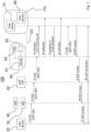
- Figure 1
- shows an exemplary message flow diagram for establishing a VoIP communication session using an exemplary communication system including at least one VoIP capable device associated with a customer, and
- Figure 2
- shows a further exemplary message flow diagram for establishing a VoIP communication session using an exemplary communication system including the at least one VoIP capable device depicted in
figure 1 and in addition a non-VoIP capable device associated with the customer. - Referring now to
figure 1 , anexemplary communication system 100 is schematically depicted, which is configured to preferably manage and/or signal VoIP calls and to preferably support the establishment of a real-time VoIP communication sessions between calling parties and called parties. For example, a called party may be a customer and/or at least one device associated with the customer. The customer is symbolized infigure 1 and also infigure 2 by a circle carrying thereference number 110. - In the preferred embodiment shown in
figure 1 , two VoIPcapable devices customer 110. In practice, at least one VoIP capable device is associated with a customer. For example, VoIPcapable device 70 can be implemented as a smartphone, whereas VoIPcapable device 80 can be implemented as a softphone on a computer. Preferably, each of the VoIPcapable devices capable devices - In particular, the
exemplary communication system 100 offigure 1 may comprise a cloud-basedcall management system 60 and anIP multimedia subsystem 30, also called IMS system. The cloud-basedcustomer management system 60, in the following also called CMS system, is registered on theIMS system 30. For example an IP address is assigned to theCMS system 60. In particular, theCMS system 60 can be registered onIMS system 30 by using its IP address. The IP address of theCMS system 60 may be stored for example on ahome subscriber server 40, which is accessible by theIMS system 60 or which may be part of theIMS system 30. Preferably, theIMS system 30 is configured to notify, once theCMS system 60 is registered on theIMS system 30, theCMS system 60 of any invite message concerning a VoIP call. - At
least customer 110 and the VoIPcapable devices customer 110, are registered on the cloud-basedcustomer management system 60. In order to registercustomer 110 and the VoIPcapable devices customer 110, the addresses assigned to the VoIPcapable devices customer 110 and the respective addresses can be stored on theCMS system 60. Preferably, these data can be stored in astorage 62 implemented on theCMS system 60. For example, thestorage 62 may store the data in form of a database or look-up table. It should be noted, that in practice identifications or identifiers of a plurality of customers and the respective addresses of their VoIP capable devices can managed by theCMS system 60 and stored on theCMS system 60 in thestorage 62, respectively. The identifier is preferably a unique identifier of the respective customer. - The cloud-based
customer management system 60 may further comprise at least oneserver device 61 or a network of connected server devices, which is connectable to thestorage 62. TheCMS system 60 and theserver device 61, respectively, may be configured to generate for example a call history with respect to each registered customer. Afurther storage 63 can be implemented in theCMS system 60, which might be configured to store a call history of each VoIP communication session concerning the respective customer. For example, with respect to each customer registered on theCMS system 60, information about each incoming and/or outgoing VoIP call, the interruption or termination of an established VoIP session, each VoIP call acceptance or the deny of a VoIP request, a missed VoIP call and the like call can be stored as a call history onstorage 63. At least some of the information/call history stored with respect to a registered customer can be provided to the respective customer and the registered devices associated with the respective customer, respectively. The information can be provided by and/or stored on theCMS system 60 in form of a webpage retrievable by the respective customer over the Internet, for example. - It should be noted that at least one of the VoIP
capable devices customer 110 can be implemented to retrieve and download from the cloud-basedcustomer management system 60 and thestorage 63, respectively, at least the portion of the call history belonging to thecustomer 110. Therefore, a respective software client (APP) can be stored on and executed by the respective VoIPcapable devices - Preferably, the identifier of the
customer 110 and/or the addresses of the VoIPcapable devices customer 110 may be stored on theIMS system 30 and on thehome subscriber server 40, respectively, to inform theIMS system 30 that thecustomer 110 and the customer'sdevices communication system 100. - In a preferred embodiment, the
CMS system 60 and theIMS system 30 can communicate via aVoIP gateway 50, which may belong to theIMS system 30. The operation and task of such aVoIP gateway 50 are known to a person skilled in the art. Preferably, the IP address of theVoIP gateway 50 is known to theIMS system 30 and theCMS system 60, whereas theVoIP gateway 50 knows an IP address of theCMS system 60 and an IP address of theIMS system 30 so that messages may be transmitted from theIMS system 30 via theVoIP gateway 50 to theCMS system 60 and vice versa.. - Also shown in
figure 1 is a callingparty 20, which may be implemented as a VoIP-capable and SIP (Session Initiation Protocol)capable telephone 20. SIP and IMS is, for example, described by Gerd Siegmund in the reference book " Hüthig Verlag. - It should be noted, that the
CMS system 60 and the VoIPcapable devices data network 120, e.g. the Internet, with each other. In practice, each of the VoIPcapable devices data network 120 via an access network. In the preferred embodiment, the VoIPcapable device 70 comprises, for example, a wireless communication interface configured to communicate via a radio access network like LTE with the IP-baseddata network 120. Furthermore, the VoIPcapable device 80 may comprise a fixed-line communication interface configured to communicate via fixed-line access network like DSL with the IP-baseddata network 120. In a similar way, theVoIP gateway 50 and theCMS system 60 may be each configured to communicate via an IP-based data network, e.g. the Internet, with each other. - Now a preferred scenario is described in connection with
figure 1 to illustrate the function and operation of theexemplary communication system 100. - It is assumed, that the calling
device 20 now generates a VoIP session request message, also called an invite message, using the Session Initiation Protocol SIP. The invite message preferably includes an SDP (Session Description Protocol) offer and, as an address, for example the phone number or IP address of the customer'sdevice 70. The SDP offer may include attributes of the multimedia data stream to be used; in the present case attributes of a VoIP session. Furthermore, the SDP offer preferably contains a list of different codecs supported by the callingdevice 20. As is known, SDP is used for example to support negotiation of the codec to be used, transport protocols and addresses between a calling party and a called party. Atstep 1, the VoIP session request message is sent from the callingdevice 20 to theIMS system 30 using SIP in a known manner. - The VoIP session request message is received and analyzed by the
IMS system 30 to determine what to do. Preferably, theIMS system 30 checks, whether the phone number included in the VoIP session request message is for example registered on the home subscriber server 40.In the present exemplary case, theSMS system 30 recognizes that a VoIP session shall be established tocustomer 110 and thedevice 70, respectively, and thatcustomer 110 is entitled to get access to the VoIP service of thecommunication system 100. As a result, the VoIP session request message is preferably forwarded, atstep 2, by theIMS system 30 to theVoIP gateway 50 using the IP address of theVoIP gateway 50. Atstep 3, the VoIP session request message is preferably forwarded by theVoIP gateway 50 to the cloud-basedcustomer management system 60 using the IP address of theCMS system 60 and theserver 61, respectively. - The
CMS system 60 and theserver 61, respectively, is configured for example to analyze the received VoIP session request message in connection with the data stored instorage 62. As a result, theCMS system 60 recognizes that the phone number ofdevice 70 included in the VoIP session request message is linked along with the phone number of thedevice 80 tocustomer 110. TheCMS system 60 and theserver 61, respectively, is further configured, to generate a first notification message including an information of an incoming VoIP call, for example the calling number of thedevice 20 and/or a user name. In addition, the first notification message may include acommand causing devices - It should be noted, that although the calling party has used the phone number of the
device 70 it is preferably up to thecustomer 110 to decide which of itsdevices CMS 60 is configured to send or push, atstep 4, a first notification message to each of the at least two VoIPcapable devices customer 110 via the IP-baseddata network 120 using for example IP addresses assigned to the VoIPcapable devices capable devices - At
step 5, theCMS system 60 is notified preferably by thecustomer 110 of the VoIP capable device of the two VoIPcapable devices device 70 shall be used with respect to the incoming VoIP call. For example, thecustomer 110 may cause thedevice 70, for example by entering a respective command on thedevice 70, to send, by using the IP address of theCMS system 60, an identification message to theCMS system 60 indicating thatdevice 70 is prepared to accept the incoming VoIP call. - The
CMS system 60 and theserver 61, respectively, is preferably configured to send or push, atstep 6, in response to the identification message received from the VoIP capable device 70 a second notification message to the VoIPcapable device 80 not notified to theCMS system 60, wherein the second notification message includes a command to cause theVoIP device 80 to stop generating the optic and/or ringing signal. - Furthermore, the
CMS system 60 and theserver 61, respectively, is preferably configured to forward, atstep 7, in response to the identification message received from the VoIPcapable device 70 the VoIP session request message only to theVoIP device 70 notified to theCMS system 60. - The
VoIP device 70 is preferably configured to - i) generate in response to the SDP offer included in the VoIP session request message received from the CMS system 60 a message including an SDP answer and
- ii) to send this message, at step 8 to the
CMS system 60 andServer 61, respectively. - The
CMS system 60 and theserver 61, respectively, is configured to forward the message including the SDP answer, if implemented, to theVoIP gateway 50 atstep 9, wherein theIMS system 30, is configured to forward the received SDP answer to the callingdevice 20 atstep 11. It is to be noted, that the message including the SDP answer may also include the address of the callingdevice 20. - Now, the requested real- time VoIP communication session can be established between the calling
device 20 and the customer'sdevice 70 atstep 12 in order to exchange VoIP signals. - It should be noted, that if only one VoIP capable device,
e.g. device 70, is associated with thecustomer 110, the operation and function of thecommunication system 100 is very similar to that illustrated above in connection with two VoIPcapable devices step 4 only to thedevice 70 andstep 6 is omitted. - Furthermore, it should be noted that the
CMS system 60 can be preferably configured to collect meta data of the callingparty 20, which are stored for example on theIMS system 30, and to push them to the VoIPcapable devices 70 and/or 80 associated with thecustomer 110 acting as a called party. The meta data may include information about the name of the calling user, the phone number and/or an IP address of thedevice 20. In addition, the current state of each established real-time VoIP sessions, .e.g. the VoIP session established atstep 12, the duration of an ongoing VoIP session, termination or holding of an VoIP session may be protocolled by theCMS system 60 and the respective information may be stored ion thestorage 63 for further use. In particular, theCMS system 60 may inform theVoIP devices customer 110 on that VoIP capable device, which is currently the called endpoint of the VoIP session established atstep 12. - Now, a further scenario is described in connection with
figure 2 to illustrate the operation and function of a communication system 100'. The communication system 100' differs from thecommunication system 100 as shown infigure 1 in that a non-VoIPcapable device 90 is now associated along with the VoIPcapable devices customer 110. The non-VoIPcapable device 90 may be a TV device or a smart speaker. It is assumed, that the non-VoIPcapable device 90 is a TV device, which does not support the SIP protocol. However, an IP address can be assigned to theTV device 90. Therefore, thecustomer 110 and thedevices 70 to 90 associated with thecustomer 110 are now registered on theCMS system 60. For example, an identifier of thecustomer 110 is stored together with the respective addresses of the VoIPcapable devices capable device 90 in thestorage 62. It should be noted that the non-VoIPcapable device 90 associated with thecustomer 110 can be implemented to retrieve and download from the cloud-basedcustomer management system 60 at least the portion of the call history belonging to thecustomer 110. Therefore, a respective software client (APP) can be stored on and executed by the non-VoIP capable device. - For the sake of simplicity it is assumed, that the calling
device 20 now generates similar to the first scenario illustrated above a VoIP session request message, also called an invite message, using the Session Initiation Protocol SIP. The invite message preferably includes an SDP (Session Description Protocol) offer and, as an address, for example the phone number and/or IP address of the VoIPcapable device 70 associated with thecustomer 110, which acts as a called party. As a result, steps 1 to 3 as depicted infigure 2 are preferably identical tosteps 1 to 3 offigure 1 . Therefore, it is now assumed that theCMS system 60 and theserver 61, respectively has received the VoIP session request message from theVoIP gateway 50 as illustrated above in connection withfigure 1 . - The
CMS system 60 and theserver 61, respectively, is configured to analyze the received VoIP session request message in connection with the data stored instorage 62. As a result, theCMS system 60 recognizes that the phone number ofdevice 70 included in the VoIP session request message is linked along with the registered addresses of thedevices customer 110. TheCMS system 60 and theserver 61, respectively, is further configured, to generate a first notification message for each of thedevices device 20 and/or a user name. In addition, each first notification message may include acommand causing devices TV device 90 may include a command, which causes theTV device 90, if the command is executed by theTV device 90, to depict for example symbols of the VoIPcapable devices TV device 90 comprises a touch screen., - It should be noted, that although the calling party has used the phone number of the
device 70 it is preferably up to thecustomer 110 to decide which of itsdevices CMS 60 is configured to send or push, atstep 4, the respective first notification message to each of the two VoIPcapable devices TV device 90 via the IP-baseddata network 120 using for example the IP addresses assigned to the VoIPcapable devices TV device 90. Preferably, each of the VoIPcapable devices TV device 90 may be further configured to execute the command contained in the respective first notification message, which causes for example therespective devices device 90 may be configured to depict for example symbols of the VoIPcapable devices - At
step 5, theCMS system 60 is notified preferably by thecustomer 110 of the VoIP capable device of the two VoIPcapable devices device 70 shall accept the incoming VoIP call. For example, thecustomer 110 may touch with a finger the symbol of the VoIPcapable device 70 on the touch screen of theTV device 90, thereby causing the TV-device 90 to send, by using the IP address of theCMS system 60, an identification message to theCMS system 60 indicating that a different device, namelydevice 70 is prepared to accept, i.e. to receive the incoming VoIP call. - The
CMS system 60 and theserver 61, respectively, is preferably configured to send or push, atstep 6, in response to the identification message received from the TV device 90 a second notification message to both the VoIPcapable device 80 and to theTV device 90 which have been not notified to theCMS system 60, wherein the second notification message received by thedevice 80 may include a command to cause the VoIPcapable device 80 to stop generating the optic and/or ringing signal, whereas the second notification message received by theTV device 90 may include a command to cause theTV device 80 to stop generating the optic and/or ringing signal and/or to depict an information on the touch screen indicating that theVoIP device 70 has been successfully selected to accept the incoming VoIP call. - Furthermore, the
CMS system 60 and theserver 61, respectively, is preferably configured to forward, atstep 7, in response to the identification message received from theTV device 90 the VoIP session request message only to the selectedVoIP device 70 notified to theCMS system 60. - The
VoIP device 70 is preferably configured, to - i) generate in response to the SDP offer included in the VoIP session request message received from the CMS system 60 a message including an SDP answer and
- ii) to send this message, at step 8 to the
CMS system 60 andServer 61, respectively. - The
CMS system 60 and theserver 61, respectively, is configured to forward the message including the SDP answer, if implemented, to theVoIP gateway 50 atstep 9, wherein theIMS system 30, is configured to forward the received SDP answer to the callingdevice 20 atstep 11. It is to be noted, that the message including the SDP answer may also include the address of the callingdevice 20. - Now, the requested real- time VoIP communication session can be established between the calling
device 20 and the customer'sdevice 70 atstep 12 in order to exchange VoIP signals.
Claims (14)
- A method for managing and/or signaling at least one VoIP call using a communication system (100; 100') that comprises an IMS (IP multimedia subsystem) system (30) and a cloud-based customer management system (60) registered on the IMS system (30), wherein a VoIP capable device (70) is associated with a customer (110), wherein an address is assigned to the VoIP capable device (70) and registered together with an identifier of the customer (110) on the cloud-based customer management system (60), the method comprising the steps of:a) Receiving, at the IMS system (30), a VoIP session request message from a calling party (20), wherein the VoIP session request message includes an SDP (session description information) offer and the address of the VoIP capable device (70);b) forwarding, by the IMS system (30), the VoIP session request message to the cloud-based customer management system (60);c) Sending, by the cloud-based customer management system (60), in response to the VoIP session request message a first notification message to the VoIP capable device (70), the first notification message including an information of an incoming VoIP call;d) Notifying, in response to the first notification message, the cloud-based customer management system (60), that the VoIP capable device (70) is prepared to accept the incoming VoIP call;e) Forwarding, by the cloud-based customer management system (60), the VoIP session request message to the VoIP capable device (70);f) Sending, by the VoIP capable device (70), a message including an SDP answer in response to the SDP offer to the cloud-based customer management system (60);g) Forwarding the SDP answer, by the cloud-based customer management system (60), to the IMS system (30).
- The method according to claim 1, wherein at least two VoIP capable devices (70, 80) are associated with the customer (110), a different address being assigned to each of the VoIP capable devices (70, 80), wherein the different addresses are registered together with the identifier of the customer (110) on the cloud-based customer management system (60), the method comprising the steps of:a) Receiving, at the IMS system (30), a VoIP session request message from a calling party (20), a VoIP session request message including an SDP (session description information) offer and the address of one of the at least two VoIP capable devices (70, 80);b) forwarding, by the IMS system (30), the VoIP session request message to the cloud-based customer management system (60);c) Sending, by the cloud-based customer management system (60), in response to the VoIP session request message a first notification message to each of the at least two VoIP capable devices (70, 80) associated with the customer (110), the first notification message including an information about an incoming VoIP call;d) Notifying the cloud-based customer management system (60) of the VoIP capable device (70) of the at least two VoIP capable devices (70, 80), which is prepared to accept the incoming VoIP call;e) Forwarding, by the cloud-based customer management system (60), the VoIP session request message only to said VoIP capable device (70) notified at step d) to the cloud-based customer management system (60);f) Sending, by said VoIP capable device (70) notified at step d) to the cloud-based customer management system (60), a message including an SDP answer in response to the SDP offer to the cloud-based customer management system (60);g) Forwarding the SDP answer, by the cloud-based customer management system (60), to the IMS system (30).
- The method according to claim 1 or 2, wherein
step g) comprises the steps of forwarding the SDP answer from the IMS system (30) to the calling party (20) and establishing a VoIP session between the calling party (20) and said VoIP capable device (70) notified at step d) to the cloud-based customer management system (60). - The method according to any one of the preceding claims,
wherein step d) comprises the step of sending, only by said VoIP capable device (70), which is prepared to accept the incoming VoIP call, in response to the first notification message a message to the cloud-based customer management system (60), indicating the acceptance of the incoming VoIP call. - The method according to any one of the preceding claims, whereina non-VoIP capable device (90) is associated with the customer (110), wherein step c) comprises the step of sending, by the cloud-based customer management system (60), a first notification message including an information about an incoming VoIP call also to the non-VoIP capable device (90) associated with the customer (110), and whereinstep d) comprises the steps of selecting, by the customer (110), only the VoIP capable device (70) of the at least two VoIP capable devices (70, 80), which is prepared to accept the incoming VoIP call, by using the non-VoIP capable device (90) and sending, by the non-VoIP capable device (90), an information about the selected VoIP capable device (70) to the cloud-based customer management system (90).
- The method according to any one of the preceding claims,
wherein, in response to the first notification message received at step c), an optic and/or acoustic signal indicating an incoming VoIP call is generated by each of the devices (70, 80, 90) associated with the customer (110). - The method according to claim 6 in connection with claim 2,
wherein a second notification message is sent, by the cloud-based customer management system (60), to each of the VoIP capable device (80) not notified at step d) to the cloud-based customer management system, wherein each of the second notification message includes a command to stop generating the optic and/or acoustic signal. - A communication system (100, 110', comprising an IMS (IP multimedia subsystem) system (30) anda cloud-based customer management system (60) registered on the IMS system (30) and configured to communicate with the IMS system (30), wherein at least one VoIP capable device (70) is associated with a customer (110), an address being assigned to the at least one VoIP capable device (70), wherein the address is registered together with an identifier of the customer on the cloud-based customer management system (60), whereinthe cloud-based customer management system (60) is configured to- receive, from the IMS system (30), a VoIP session request message generated by a calling party (20), the VoIP session request message including an SDP (session description information) offer and the address of the at least one VoIP capable device (70),- send, in response to the VoIP session request message, a notification message to the at least one VoIP capable device (70) associated with the customer (110), the notification message including an information about an incoming VoIP call,- receive a message notifying the cloud-based customer management system (60) of the VoIP capable device (70), which is prepared to accept the incoming VoIP call,- forward the VoIP session request message only to said VoIP capable device (70) notified to the cloud-based customer management system (60),- receive a message including an SDP answer from said VoIP capable device (70) notified to the cloud-based customer management system, and to- forward the SDP answer to the IMS system (30) for forwarding the SDP answer to a calling party (20).
- The communication system according to claim 8, whereinat least two VoIP capable devices (70, 80) are associated with the customer (110), a different address being assigned to each of the at least two VoIP capable devices (70, 80) associated with the customer (110), wherein the different addresses are registered together with the identifier of the customer (110) on the cloud-based customer management system (60), whereinthe cloud-based customer management system (60) is configured to- receive, from the IMS system (30), a VoIP session request message generated by a calling party (20), the VoIP session request message including an SDP (session description information) offer and an address of one (70) of the at least two VoIP capable devices (70, 80),- send, in response to the VoIP session request message, a notification message to each of the at least two VoIP capable devices (70, 80) associated with the customer (110), the notification message including an information about an incoming VoIP call,- receive a message notifying the cloud-based customer management system (60) of the VoIP capable device (70) of the at least two VoIP capable devices (70, 80), which is prepared to accept the incoming VoIP call,- forward the VoIP session request message only to said VoIP capable device (70) notified to the cloud-based customer management system (60),- receive a message including an SDP answer from said VoIP capable device (70) notified to the cloud-based customer management system (60), and to- forward the SDP answer to the IMS system (30) for forwarding the SDP answer to a calling party (20).
- The communication system according to claim 8 or 9, whereina non-VoIP capable device (90) is associated with the customer (110), wherein the cloud-based customer management system (60) is configured to send a notification message including an information about an incoming VoIP call also to the non-VoIP capable device (90) associated with the customer (110), and whereinthe non-VoIP capable device (90) is configured to generate in response to a customer's action an information about the VoIP capable device (70), which is prepared to accept the incoming VoIP call and to send this information to the cloud-based customer management system (60).
- The communication system according to any one of the claims 8 to 10, wherein the cloud-based customer management system (60) is configured to generate and store a call history with respect to the customer.
- The communication system according to claim 11, wherein
the call history includes information about each incoming and/or outgoing VoIP call, an interruption or termination of an established VoIP session, a VoIP call acceptance or the deny of a VoIP request. - The communication system according to claim 11 or 12, wherein
the cloud-based customer management system (60) is configured to provide at least a portion of the stored call history retrievable by the customer. - The communication system according to claim 13, wherein
at least the portion of the stored call history is stored on the CMS system 60 in form of a webpage retrievable by the customer.
Priority Applications (2)
| Application Number | Priority Date | Filing Date | Title |
|---|---|---|---|
| EP22158067.3A EP4231617B1 (en) | 2022-02-22 | 2022-02-22 | Method for managing and/or signaling at least one voip call and a communication system |
| EP23157836.0A EP4231618B1 (en) | 2022-02-22 | 2023-02-21 | Method for managing and/or signaling at least one voip call and a communication system |
Applications Claiming Priority (1)
| Application Number | Priority Date | Filing Date | Title |
|---|---|---|---|
| EP22158067.3A EP4231617B1 (en) | 2022-02-22 | 2022-02-22 | Method for managing and/or signaling at least one voip call and a communication system |
Publications (2)
| Publication Number | Publication Date |
|---|---|
| EP4231617A1 true EP4231617A1 (en) | 2023-08-23 |
| EP4231617B1 EP4231617B1 (en) | 2025-10-22 |
Family
ID=80447027
Family Applications (2)
| Application Number | Title | Priority Date | Filing Date |
|---|---|---|---|
| EP22158067.3A Active EP4231617B1 (en) | 2022-02-22 | 2022-02-22 | Method for managing and/or signaling at least one voip call and a communication system |
| EP23157836.0A Active EP4231618B1 (en) | 2022-02-22 | 2023-02-21 | Method for managing and/or signaling at least one voip call and a communication system |
Family Applications After (1)
| Application Number | Title | Priority Date | Filing Date |
|---|---|---|---|
| EP23157836.0A Active EP4231618B1 (en) | 2022-02-22 | 2023-02-21 | Method for managing and/or signaling at least one voip call and a communication system |
Country Status (1)
| Country | Link |
|---|---|
| EP (2) | EP4231617B1 (en) |
Citations (3)
| Publication number | Priority date | Publication date | Assignee | Title |
|---|---|---|---|---|
| US20070140150A1 (en) * | 2005-12-15 | 2007-06-21 | Andre Beck | Method and network for providing service blending to a subscriber |
| WO2011126505A1 (en) * | 2010-04-07 | 2011-10-13 | Apple Inc. | Establishing online communication sessions between client computing devices |
| US20150189073A1 (en) * | 2005-11-25 | 2015-07-02 | At&T Intellectual Property I, L.P. | Displaying call log information on a display device |
-
2022
- 2022-02-22 EP EP22158067.3A patent/EP4231617B1/en active Active
-
2023
- 2023-02-21 EP EP23157836.0A patent/EP4231618B1/en active Active
Patent Citations (3)
| Publication number | Priority date | Publication date | Assignee | Title |
|---|---|---|---|---|
| US20150189073A1 (en) * | 2005-11-25 | 2015-07-02 | At&T Intellectual Property I, L.P. | Displaying call log information on a display device |
| US20070140150A1 (en) * | 2005-12-15 | 2007-06-21 | Andre Beck | Method and network for providing service blending to a subscriber |
| WO2011126505A1 (en) * | 2010-04-07 | 2011-10-13 | Apple Inc. | Establishing online communication sessions between client computing devices |
Non-Patent Citations (1)
| Title |
|---|
| "Technik der Netze 2", 2009, VERLAG |
Also Published As
| Publication number | Publication date |
|---|---|
| EP4231618A1 (en) | 2023-08-23 |
| EP4231617B1 (en) | 2025-10-22 |
| EP4231618B1 (en) | 2026-04-01 |
Similar Documents
| Publication | Publication Date | Title |
|---|---|---|
| US10484436B2 (en) | User device selection | |
| EP1652359B1 (en) | Method and system for suppressing early media in a communications network | |
| CN105282730B (en) | Terminal communications status acquisition methods and system and application server in IMS network | |
| CN101277342A (en) | A method, device and system for realizing fork business | |
| EP3172880B1 (en) | Method of and communications handling equipment for controlling communication session establishment in a multimedia communications network. | |
| US7016359B2 (en) | Method for providing hybrid voice and packet data services to a mobile station | |
| EP2068524A1 (en) | A method and a system for acquiring the transmission path of the sip message | |
| US11070668B2 (en) | Advanced call log notifications | |
| US9071690B2 (en) | Call transfer processing in SIP mode | |
| CN102652434B (en) | Method and apparatus for delivering called party naming information to a calling party | |
| US10212193B2 (en) | Service support for suspended and inactive subscribers | |
| EP4231617B1 (en) | Method for managing and/or signaling at least one voip call and a communication system | |
| CN101365157A (en) | A service trigger method, system and device | |
| US20150031341A1 (en) | Method for responding to push notification based communication request | |
| EP2064864B1 (en) | Remote monitoring of phone calls | |
| EP4342165A1 (en) | System and method for providing an enhanced feature for a caller ring back tone | |
| US11057517B2 (en) | Method for managing a failure to establish a communication between a first and a second terminal | |
| EP2092724A1 (en) | Method and server for filtering telephone calls | |
| EP4239977B1 (en) | Methods of initiating telecommunications sessions and devices, servers and computer software for performing the methods | |
| EP4462753A1 (en) | Method for managing at least one voip call and a communictaion system | |
| CN113630509B (en) | IP phone calling system and calling method | |
| RU2808170C2 (en) | System for making and receiving calls to second number | |
| EP3337118A1 (en) | Method for an enhanced control function selection in a communication network, communication network, home subscriber server, program and computer program product | |
| KR101584901B1 (en) | System and method of providing enterprise telephone service using personal mobile terminal | |
| KR101562470B1 (en) | Signaling gateway and method of providing enterprise telephone service using personal mobile terminal |
Legal Events
| Date | Code | Title | Description |
|---|---|---|---|
| PUAI | Public reference made under article 153(3) epc to a published international application that has entered the european phase |
Free format text: ORIGINAL CODE: 0009012 |
|
| STAA | Information on the status of an ep patent application or granted ep patent |
Free format text: STATUS: THE APPLICATION HAS BEEN PUBLISHED |
|
| AK | Designated contracting states |
Kind code of ref document: A1 Designated state(s): AL AT BE BG CH CY CZ DE DK EE ES FI FR GB GR HR HU IE IS IT LI LT LU LV MC MK MT NL NO PL PT RO RS SE SI SK SM TR |
|
| STAA | Information on the status of an ep patent application or granted ep patent |
Free format text: STATUS: REQUEST FOR EXAMINATION WAS MADE |
|
| 17P | Request for examination filed |
Effective date: 20240119 |
|
| RBV | Designated contracting states (corrected) |
Designated state(s): AL AT BE BG CH CY CZ DE DK EE ES FI FR GB GR HR HU IE IS IT LI LT LU LV MC MK MT NL NO PL PT RO RS SE SI SK SM TR |
|
| STAA | Information on the status of an ep patent application or granted ep patent |
Free format text: STATUS: EXAMINATION IS IN PROGRESS |
|
| 17Q | First examination report despatched |
Effective date: 20240731 |
|
| REG | Reference to a national code |
Ref country code: DE Ref legal event code: R079 Ipc: H04L0065101600 Ref country code: DE Ref legal event code: R079 Ref document number: 602022023294 Country of ref document: DE Free format text: PREVIOUS MAIN CLASS: H04M0003420000 Ipc: H04L0065101600 |
|
| GRAP | Despatch of communication of intention to grant a patent |
Free format text: ORIGINAL CODE: EPIDOSNIGR1 |
|
| STAA | Information on the status of an ep patent application or granted ep patent |
Free format text: STATUS: GRANT OF PATENT IS INTENDED |
|
| RIC1 | Information provided on ipc code assigned before grant |
Ipc: H04M 7/00 20060101ALI20250506BHEP Ipc: H04M 3/42 20060101ALI20250506BHEP Ipc: H04L 65/1094 20220101ALI20250506BHEP Ipc: H04L 65/1069 20220101ALI20250506BHEP Ipc: H04L 65/1016 20220101AFI20250506BHEP |
|
| INTG | Intention to grant announced |
Effective date: 20250514 |
|
| GRAS | Grant fee paid |
Free format text: ORIGINAL CODE: EPIDOSNIGR3 |
|
| GRAA | (expected) grant |
Free format text: ORIGINAL CODE: 0009210 |
|
| STAA | Information on the status of an ep patent application or granted ep patent |
Free format text: STATUS: THE PATENT HAS BEEN GRANTED |
|
| AK | Designated contracting states |
Kind code of ref document: B1 Designated state(s): AL AT BE BG CH CY CZ DE DK EE ES FI FR GB GR HR HU IE IS IT LI LT LU LV MC MK MT NL NO PL PT RO RS SE SI SK SM TR |
|
| REG | Reference to a national code |
Ref country code: CH Ref legal event code: F10 Free format text: ST27 STATUS EVENT CODE: U-0-0-F10-F00 (AS PROVIDED BY THE NATIONAL OFFICE) Effective date: 20251022 Ref country code: GB Ref legal event code: FG4D |
|
| REG | Reference to a national code |
Ref country code: DE Ref legal event code: R096 Ref document number: 602022023294 Country of ref document: DE |
|
| REG | Reference to a national code |
Ref country code: IE Ref legal event code: FG4D |
|
| REG | Reference to a national code |
Ref country code: NL Ref legal event code: MP Effective date: 20251022 |
|
| PG25 | Lapsed in a contracting state [announced via postgrant information from national office to epo] |
Ref country code: NL Free format text: LAPSE BECAUSE OF FAILURE TO SUBMIT A TRANSLATION OF THE DESCRIPTION OR TO PAY THE FEE WITHIN THE PRESCRIBED TIME-LIMIT Effective date: 20251022 |
|
| PGFP | Annual fee paid to national office [announced via postgrant information from national office to epo] |
Ref country code: GB Payment date: 20260219 Year of fee payment: 5 |
|
| PG25 | Lapsed in a contracting state [announced via postgrant information from national office to epo] |
Ref country code: ES Free format text: LAPSE BECAUSE OF FAILURE TO SUBMIT A TRANSLATION OF THE DESCRIPTION OR TO PAY THE FEE WITHIN THE PRESCRIBED TIME-LIMIT Effective date: 20251022 |
|
| REG | Reference to a national code |
Ref country code: LT Ref legal event code: MG9D |
|
| PG25 | Lapsed in a contracting state [announced via postgrant information from national office to epo] |
Ref country code: NO Free format text: LAPSE BECAUSE OF FAILURE TO SUBMIT A TRANSLATION OF THE DESCRIPTION OR TO PAY THE FEE WITHIN THE PRESCRIBED TIME-LIMIT Effective date: 20260122 |
|
| PGFP | Annual fee paid to national office [announced via postgrant information from national office to epo] |
Ref country code: DE Payment date: 20260217 Year of fee payment: 5 |
|
| PG25 | Lapsed in a contracting state [announced via postgrant information from national office to epo] |
Ref country code: HR Free format text: LAPSE BECAUSE OF FAILURE TO SUBMIT A TRANSLATION OF THE DESCRIPTION OR TO PAY THE FEE WITHIN THE PRESCRIBED TIME-LIMIT Effective date: 20251022 Ref country code: AT Free format text: LAPSE BECAUSE OF FAILURE TO SUBMIT A TRANSLATION OF THE DESCRIPTION OR TO PAY THE FEE WITHIN THE PRESCRIBED TIME-LIMIT Effective date: 20251022 Ref country code: FI Free format text: LAPSE BECAUSE OF FAILURE TO SUBMIT A TRANSLATION OF THE DESCRIPTION OR TO PAY THE FEE WITHIN THE PRESCRIBED TIME-LIMIT Effective date: 20251022 |
|
| PGFP | Annual fee paid to national office [announced via postgrant information from national office to epo] |
Ref country code: AT Payment date: 20260301 Year of fee payment: 5 |
|
| REG | Reference to a national code |
Ref country code: AT Ref legal event code: MK05 Ref document number: 1850257 Country of ref document: AT Kind code of ref document: T Effective date: 20251022 |
|
| PG25 | Lapsed in a contracting state [announced via postgrant information from national office to epo] |
Ref country code: RS Free format text: LAPSE BECAUSE OF FAILURE TO SUBMIT A TRANSLATION OF THE DESCRIPTION OR TO PAY THE FEE WITHIN THE PRESCRIBED TIME-LIMIT Effective date: 20260122 |
|
| PG25 | Lapsed in a contracting state [announced via postgrant information from national office to epo] |
Ref country code: IS Free format text: LAPSE BECAUSE OF FAILURE TO SUBMIT A TRANSLATION OF THE DESCRIPTION OR TO PAY THE FEE WITHIN THE PRESCRIBED TIME-LIMIT Effective date: 20260222 |
|
| PGFP | Annual fee paid to national office [announced via postgrant information from national office to epo] |
Ref country code: FR Payment date: 20260223 Year of fee payment: 5 |
|
| PG25 | Lapsed in a contracting state [announced via postgrant information from national office to epo] |
Ref country code: PT Free format text: LAPSE BECAUSE OF FAILURE TO SUBMIT A TRANSLATION OF THE DESCRIPTION OR TO PAY THE FEE WITHIN THE PRESCRIBED TIME-LIMIT Effective date: 20260223 |
|
| PG25 | Lapsed in a contracting state [announced via postgrant information from national office to epo] |
Ref country code: PL Free format text: LAPSE BECAUSE OF FAILURE TO SUBMIT A TRANSLATION OF THE DESCRIPTION OR TO PAY THE FEE WITHIN THE PRESCRIBED TIME-LIMIT Effective date: 20251022 |
|
| PG25 | Lapsed in a contracting state [announced via postgrant information from national office to epo] |
Ref country code: LV Free format text: LAPSE BECAUSE OF FAILURE TO SUBMIT A TRANSLATION OF THE DESCRIPTION OR TO PAY THE FEE WITHIN THE PRESCRIBED TIME-LIMIT Effective date: 20251022 |
|
| PG25 | Lapsed in a contracting state [announced via postgrant information from national office to epo] |
Ref country code: BG Free format text: LAPSE BECAUSE OF FAILURE TO SUBMIT A TRANSLATION OF THE DESCRIPTION OR TO PAY THE FEE WITHIN THE PRESCRIBED TIME-LIMIT Effective date: 20251022 |
|
| PG25 | Lapsed in a contracting state [announced via postgrant information from national office to epo] |
Ref country code: LT Free format text: LAPSE BECAUSE OF FAILURE TO SUBMIT A TRANSLATION OF THE DESCRIPTION OR TO PAY THE FEE WITHIN THE PRESCRIBED TIME-LIMIT Effective date: 20251022 |
|
| PG25 | Lapsed in a contracting state [announced via postgrant information from national office to epo] |
Ref country code: SM Free format text: LAPSE BECAUSE OF FAILURE TO SUBMIT A TRANSLATION OF THE DESCRIPTION OR TO PAY THE FEE WITHIN THE PRESCRIBED TIME-LIMIT Effective date: 20251022 |
|
| PG25 | Lapsed in a contracting state [announced via postgrant information from national office to epo] |
Ref country code: DK Free format text: LAPSE BECAUSE OF FAILURE TO SUBMIT A TRANSLATION OF THE DESCRIPTION OR TO PAY THE FEE WITHIN THE PRESCRIBED TIME-LIMIT Effective date: 20251022 |
|
| PG25 | Lapsed in a contracting state [announced via postgrant information from national office to epo] |
Ref country code: IT Free format text: LAPSE BECAUSE OF FAILURE TO SUBMIT A TRANSLATION OF THE DESCRIPTION OR TO PAY THE FEE WITHIN THE PRESCRIBED TIME-LIMIT Effective date: 20251022 |
|
| PG25 | Lapsed in a contracting state [announced via postgrant information from national office to epo] |
Ref country code: EE Free format text: LAPSE BECAUSE OF FAILURE TO SUBMIT A TRANSLATION OF THE DESCRIPTION OR TO PAY THE FEE WITHIN THE PRESCRIBED TIME-LIMIT Effective date: 20251022 |
|
| PG25 | Lapsed in a contracting state [announced via postgrant information from national office to epo] |
Ref country code: CZ Free format text: LAPSE BECAUSE OF FAILURE TO SUBMIT A TRANSLATION OF THE DESCRIPTION OR TO PAY THE FEE WITHIN THE PRESCRIBED TIME-LIMIT Effective date: 20251022 |
|
| PG25 | Lapsed in a contracting state [announced via postgrant information from national office to epo] |
Ref country code: SK Free format text: LAPSE BECAUSE OF FAILURE TO SUBMIT A TRANSLATION OF THE DESCRIPTION OR TO PAY THE FEE WITHIN THE PRESCRIBED TIME-LIMIT Effective date: 20251022 |
|
| PG25 | Lapsed in a contracting state [announced via postgrant information from national office to epo] |
Ref country code: SE Free format text: LAPSE BECAUSE OF FAILURE TO SUBMIT A TRANSLATION OF THE DESCRIPTION OR TO PAY THE FEE WITHIN THE PRESCRIBED TIME-LIMIT Effective date: 20251022 |