EP4231523A1 - Energy harvesting module and method for manufacturing same - Google Patents
Energy harvesting module and method for manufacturing same Download PDFInfo
- Publication number
- EP4231523A1 EP4231523A1 EP21882508.1A EP21882508A EP4231523A1 EP 4231523 A1 EP4231523 A1 EP 4231523A1 EP 21882508 A EP21882508 A EP 21882508A EP 4231523 A1 EP4231523 A1 EP 4231523A1
- Authority
- EP
- European Patent Office
- Prior art keywords
- energy harvesting
- frame
- partial frame
- perimeter wall
- partial
- Prior art date
- Legal status (The legal status is an assumption and is not a legal conclusion. Google has not performed a legal analysis and makes no representation as to the accuracy of the status listed.)
- Withdrawn
Links
Images


Classifications
-
- H—ELECTRICITY
- H02—GENERATION; CONVERSION OR DISTRIBUTION OF ELECTRIC POWER
- H02S—GENERATION OF ELECTRIC POWER BY CONVERSION OF INFRARED RADIATION, VISIBLE LIGHT OR ULTRAVIOLET LIGHT, e.g. USING PHOTOVOLTAIC [PV] MODULES
- H02S30/00—Structural details of PV modules other than those related to light conversion
- H02S30/10—Frame structures
-
- F—MECHANICAL ENGINEERING; LIGHTING; HEATING; WEAPONS; BLASTING
- F24—HEATING; RANGES; VENTILATING
- F24S—SOLAR HEAT COLLECTORS; SOLAR HEAT SYSTEMS
- F24S25/00—Arrangement of stationary mountings or supports for solar heat collector modules
- F24S25/20—Peripheral frames for modules
-
- H—ELECTRICITY
- H02—GENERATION; CONVERSION OR DISTRIBUTION OF ELECTRIC POWER
- H02S—GENERATION OF ELECTRIC POWER BY CONVERSION OF INFRARED RADIATION, VISIBLE LIGHT OR ULTRAVIOLET LIGHT, e.g. USING PHOTOVOLTAIC [PV] MODULES
- H02S20/00—Supporting structures for PV modules
- H02S20/30—Supporting structures being movable or adjustable, e.g. for angle adjustment
-
- H—ELECTRICITY
- H02—GENERATION; CONVERSION OR DISTRIBUTION OF ELECTRIC POWER
- H02S—GENERATION OF ELECTRIC POWER BY CONVERSION OF INFRARED RADIATION, VISIBLE LIGHT OR ULTRAVIOLET LIGHT, e.g. USING PHOTOVOLTAIC [PV] MODULES
- H02S40/00—Components or accessories in combination with PV modules, not provided for in groups H02S10/00 - H02S30/00
- H02S40/30—Electrical components
- H02S40/34—Electrical components comprising specially adapted electrical connection means to be structurally associated with the PV module, e.g. junction boxes
-
- Y—GENERAL TAGGING OF NEW TECHNOLOGICAL DEVELOPMENTS; GENERAL TAGGING OF CROSS-SECTIONAL TECHNOLOGIES SPANNING OVER SEVERAL SECTIONS OF THE IPC; TECHNICAL SUBJECTS COVERED BY FORMER USPC CROSS-REFERENCE ART COLLECTIONS [XRACs] AND DIGESTS
- Y02—TECHNOLOGIES OR APPLICATIONS FOR MITIGATION OR ADAPTATION AGAINST CLIMATE CHANGE
- Y02E—REDUCTION OF GREENHOUSE GAS [GHG] EMISSIONS, RELATED TO ENERGY GENERATION, TRANSMISSION OR DISTRIBUTION
- Y02E10/00—Energy generation through renewable energy sources
- Y02E10/50—Photovoltaic [PV] energy
Definitions
- This disclosure relates to an energy harvesting module and a method of producing the same.
- a known energy harvesting module includes an energy harvesting element, such as a solar cell element, and a frame that is attached to an outer edge of the energy harvesting element and that is formed of a plurality of partial frames.
- Patent Literature (PTL) 1 discloses an energy harvesting module in which a frame is formed of partial frames attached along four sides of a solar cell element having a rectangular flat plate shape.
- an energy harvesting module such as disclosed in PTL 1 requires a fastening device such as a screw to couple adjacent partial frames to each other, and thus has complicated production process.
- An energy harvesting module comprises: an energy harvesting element that is plate shaped; and a frame that includes a first partial frame configured to support an outer edge of a first principal surface of the energy harvesting element and a second partial frame configured to support an outer edge of a second principal surface located at a rear side of the first principal surface in the energy harvesting element, wherein the frame includes, at a first side of the energy harvesting element, an overlapping structure, a housing structure, and a fitting structure, the overlapping structure being configured to have an outer perimeter wall of one of the first partial frame and the second partial frame overlap with an inner perimeter wall of another one of the first partial frame and the second partial frame from radially outside, the housing structure being configured to have an end of the inner perimeter wall housed in a housing recess of the one of the first partial frame and the second partial frame, the fitting structure being configured to have the outer perimeter wall and the inner perimeter wall fitted in with each other.
- This configuration enables to overlap the outer perimeter wall with the inner perimeter wall from radially outside, to house an end of the inner perimeter wall in the housing recess, and to fit in the outer perimeter wall and the inner perimeter wall with each other, to thereby attach the first partial frame and the second partial frame to the outer edge of the energy harvesting element. Therefore, production process of the energy harvesting module is simplified. Further, at the first side, the housing structure prevents the one of the first partial frame and the second partial frame having the outer perimeter wall from being elastically deformed toward radially outside relative to the other one of the first partial frame and the second partial frame having the inner perimeter wall, to thereby ensure favorable fitting strength between the first partial frame and the second partial frame at the first side.
- the frame includes, at a corner of the energy harvesting element, the overlapping structure and the housing structure.
- This configuration enables the overlapping structure and the housing structure to prevent, at the corner of the energy harvesting element, the first partial frame and the second partial frame from being elastically deformed radially toward both sides relative to each other, to thereby favorably retain the fitting state between the first partial frame and the second partial frame even when the corner is subject to shock. Therefore, more favorable fitting strength can be ensured between the first partial frame and the second partial frame, at the first side.
- the frame includes, also at a second side that forms the corner with the first side, the overlapping structure, the housing structure, and the fitting structure.
- This configuration enables to more favorably retain, even when the corner is subject to shock, the fitting state between the first partial frame and the second partial frame, at the first side and the second side. Therefore, more favorable fitting strength can be ensured between the first partial frame and the second partial frame at the first side and the second side.
- the energy harvesting element has a rectangular plate shape; and the frame includes, at each side of the energy harvesting element, the overlapping structure, the housing structure, and the fitting structure, and includes, also at each corner of the energy harvesting module, the overlapping structure and the housing structure. This configuration enables to firmly support the energy harvesting element through the frame.
- the frame includes, at least at the first side, a supporting structure configured to have the first partial frame support an outer edge of the first principal surface while having the second frame support an outer edge of the second principal surface. This configuration enables to firmly support the energy harvesting element through the frame at least at the first side.
- the supporting structure is a sandwiching structure in which the first partial frame and the second partial frame are configured to act in conjunction to sandwich the energy harvesting element therebetween. This configuration enables to more firmly support the energy harvesting element through the frame at least at the first side.
- the frame includes, at least at the first side, an alternating arrangement structure in which the housing structure and the fitting structure are alternately arranged along the outer edge of the energy harvesting element.
- This configuration enables to dispose, in the alternating arrangement structure, the housing recess not adjacent to a portion corresponding to the fitting structure in the outer perimeter wall, to thereby favorably ensure bending rigidity of the outer perimeter wall in the fitting structure, which ensures more favorable fitting strength between the first partial frame and the second partial frame at least at the first side.
- a method of producing an energy harvesting module is a method of producing an energy harvesting module that includes: an energy harvesting element that is plate shaped; and a frame that includes a first partial frame configured to support an outer edge of a first principal surface of the energy harvesting element and a second partial frame configured to support an outer edge of a second principal surface located at a rear side of the first principal surface in the energy harvesting element, wherein the frame includes, at a first side of the energy harvesting element, an overlapping structure, a housing structure, and a fitting structure, the overlapping structure being configured to have an outer perimeter wall of one of the first partial frame and the second partial frame overlap with an inner perimeter wall of another one of the first partial frame and the second partial frame from radially outside, the housing structure being configured to have an end of the inner perimeter wall housed in a housing recess of the one of the first partial frame and the second partial frame, the fitting structure being configured to have the outer perimeter wall and the inner perimeter wall fitted in with each other, the method comprising:
- An energy harvesting module capable of simplifying production process and a method of producing the same are provided.
- the energy harvesting module 1 of the present embodiment illustrated in FIGS. 1 and 2 includes an energy harvesting element 2, a terminal member 3, and a frame 4.
- the frame 4 includes a first partial frame 5 and a second partial frame 6.
- the energy harvesting element 2 is a solar cell element that is configured to convert light energy such as sunlight or indoor light into electrical energy.
- the energy harvesting element 2 is not limited to a solar cell element, and may be, for example, a thermoelectric conversion element that is configured to convert thermal energy such as geothermal heat to electrical energy.
- the energy harvesting element 2 has a rectangular flat plate shape and includes a first side 2a, a second side 2b, a third side 2c, and a fourth side 2d at an outer edge of the energy harvesting element 2.
- the first side 2a and the second side 2b form a first corner 2e
- the first side 2a and the third side2c form a second corner 2f
- the second side 2b and the fourth side 2d form a third corner 2g
- the third side 2c and the fourth side 2d form a fourth corner 2h.
- the second side 2b and the third side 2c are both located adjacently to the first side 2a
- the fourth side 2d is located opposite the first side 2a.
- the fourth side 2d is provided with a terminal protrusion 2i that protrudes radially outside.
- the first side 2a, the second side 2b, and the third side 2c each have a linear shape.
- the energy harvesting element 2 includes a first principal surface 2j and a second principal surface 2k located at a rear side of the first principal surface 2j.
- a direction perpendicular to the energy harvesting element 2 that is, the thickness direction of the energy harvesting element 2
- a direction from a side corresponding to the second principal surface 2k toward a side corresponding to the first principal surface 2j is referred to as upward
- a direction from a side corresponding to the first principal surface 2j toward a side corresponding to the second principal surface 2k is referred to as downward
- a direction from inside to outside of the energy harvesting element 2 in a plane perpendicular to the vertical direction is referred to as radially outside
- a direction from outside to inside of the energy harvesting element 2 in a plane perpendicular to the vertical direction is referred to as radially inside
- a direction around the energy harvesting element 2 in a plane perpendicular to the vertical direction is referred to as perimeter direction
- the terminal member 3 includes a terminal 3a for externally withdrawing electrical power generated by the energy harvesting element 2.
- the terminal member 3 is arranged on the terminal protrusion 2i, and is configured to be held by the frame 4 with the frame 4 being attached to the outer edge of the energy harvesting element 2.
- the outer edge of the energy harvesting element 2 is covered by the frame 4 along the entire perimeter thereof, and is thereby protected.
- the frame 4 includes a first partial frame 5 configured to support the outer edge of the first principal surface 2j of the energy harvesting element 2, and a second partial frame 6 configured to support the outer edge of the second principal surface 2k of the energy harvesting element 2.
- the first partial frame 5 and the second partial frame 6 are each made of a synthetic resin such as polycarbonate resin. However, the first partial frame 5 and the second partial frame 6 are not limited to those made of a synthetic resin.
- the first partial frame 5 and the second partial frame 6 are each integrally formed by injection molding.
- the first partial frame 5 and the second partial frame 6 may each be formed by assembling a plurality of members by using a fastening device such as a screw or through adhesion, fitting, or the like.
- the thickness of the frame 4 in the vertical direction when in an assembled state may be, for example, approximately 3 mm.
- the frame 4 has an overlapping structure 9 in which the outer perimeter wall 7 of the first partial frame 5 is configured to overlap with the inner perimeter wall 8 of the second partial frame 6 from radially outside, a housing structure 11 in which an end of the inner perimeter wall 8 is configured to be housed in a housing recess 10 of the first partial frame 5, and a fitting structure 12 in which the outer perimeter wall 7 and the inner perimeter wall 8 are snap-fit with each other in the vertical direction, that is, the step-shaped portions of the partial frames are configured to be elastically deformed to move over each other in the vertical direction to thereby fit together, at the first side 2a of the energy harvesting element 2.
- the outer perimeter wall 7 and the inner perimeter wall 8 each extend along the vertical direction and extend along the perimeter direction.
- the housing recess 10 is a recessed groove extending along the perimeter direction.
- the frame 4 includes, at the first side 2a, a supporting structure 13 configured to have the first partial frame 5 support the outer edge of the first principal surface 2j and the second partial frame 6 support the outer edge of the second principal surface 2k.
- the supporting structure 13 is preferably a sandwiching structure in which the first partial frame 5 and the second partial frame 6 are configured to act in conjunction to sandwich the energy harvesting element 2 therebetween.
- the supporting structure 13 includes a first support surface 13a provided on the first partial frame 5 so as to face the first principal surface 2j, and a second support surface 13b provided on the second partial frame 6 so as to face the second principal surface 2k.
- the first partial frame 5 includes a first principal wall 14 extending radially inside from the base end of the outer perimeter wall 7 and extending along the perimeter direction.
- the housing recess 10 is provided adjacent to the outer perimeter wall 7. Further, a part of the lower surface of the first principal wall 14, the part being radially inside than the housing recess 10, constitutes the first support surface 13a.
- the second partial frame 6 includes a second principal wall 15 extending radially inside from the base end of the inner perimeter wall 8 and extending along the perimeter direction.
- the upper surface of the second principal wall 15 constitutes the second support surface 13b.
- the outer perimeter wall 7 includes a recess 12a as a step-shaped portion
- the inner perimeter wall 8 includes a protrusion 12b as a step-shaped portion.
- the recess 12a and the protrusion 12b may be replaced with each other. That is, the outer perimeter wall 7 may include the protrusion 12b as a step-shaped portion, and the inner perimeter wall 8 may have the recess 12a as a step-shaped portion.
- the fitting structure 12 is provided across a portion above the second support surface 13b and a portion below the second support surface 13b, thereby efficiently allocating enough size for the step-shaped portion of the fitting structure 12 and increasing the fitting strength.
- a corner between an upper surface and a leading surface (outer surface) of the convex portion 12b may be chamfered, or a corner between the lower surface and the inner surface of the outer perimeter wall 7 may be chamfered.
- the frame 4 includes, at the first side 2a, an alternating arrangement structure 16 in which the housing structure 11 and the fitting structure 12 are alternately arranged along the outer edge of the energy harvesting element 2. That is, in the alternating arrangement structure 16, the housing recess 10 is provided in a portion corresponding to the housing structure 11, but not in a portion corresponding to the fitting structure 12. Further, in the alternating arrangement structure 16, the length of the inner perimeter wall 8 in the vertical direction of a portion corresponding to the fitting structure 12 is shorter than the length of a portion corresponding to the housing structure 11 in the vertical direction.
- the leading surface (upper end surface) of the inner perimeter wall 8 and the lower surface of the first principal wall 14 are not in contact with each other.
- the leading surface of the inner perimeter wall 8 and the lower surface of the first principal wall 14 may be in contact with each other.
- the leading surface of the inner perimeter wall 8 and the bottom surface of the housing recess 10 may or may not be in contact with each other.
- the inner surface of the outer perimeter wall 7 and the outer surface of the inner perimeter wall 8 may preferably be in contact with each other in order to enhance fitting strength.
- the inner surface at the tip end of the inner perimeter wall 8 and the outer surface of the housing recess 10 may preferably be in contact with each other in order to enhance fitting strength.
- the leading surface (lower end surface) of the outer perimeter wall 7 and the base end surface (lower end surface) of the inner perimeter wall 8 are flush with each other. However, in the overlapping structure 9, the leading surface of the outer perimeter wall 7 and the base end surface of the inner perimeter wall 8 may not be flush with each other. In the overlapping structure 9, the inner surface of the inner perimeter wall 8 and the outer surface of the energy harvesting element 2 may or may not be in contact with each other.
- the frame 4 includes the overlapping structure 9, the housing structure 11, and the fitting structure 12, not only at the first side 2a but also at each of the second side 2b, the third side 2c, and the fourth side 2d.
- the frame 4 includes the alternating arrangement structure 16 not only at the first side 2a but also at each of the second side 2b, the third side 2c, and the fourth side 2d.
- the frame 4 includes, at the first corner 2e, the overlapping structure 9 and the housing structure 11.
- the frame 4 includes the overlapping structure 9 and the housing structure 11, also at each of the second corner 2f, the third corner 2g, and the fourth corner 2h.
- the frame 4 includes the supporting structure 13 not only at the first side 2a, but also at each of the second side 2b, the third side 2c, and the fourth side 2d.
- the frame 4 includes the supporting structure 13 also at each of the first corner 2e, the second corner 2f, the third corner 2g, and the fourth corner 2h.
- the energy harvesting module 1 of the present embodiment can readily be produced through a frame attaching step of attaching the first partial frame 5 and the second partial frame 6 to the outer edge of the energy harvesting element 2 by overlapping the outer perimeter wall 7 with the inner perimeter wall 8 from radially outside, housing the end of the inner perimeter wall 8 in the housing recess 10, and fitting in the outer perimeter wall 7 and the inner perimeter wall 8 with each other, at each of the first side 2a, the second side 2b, the third side 2c, and the fourth side 2d.
- the housing structure 11 prevents the first partial frame 5 having the outer perimeter wall 7 from relatively elastically deformed radially outside with respect to the second partial frame 6 having the inner perimeter wall 8, the second partial frame 6 having an inner perimeter wall 8, which enables to ensure, at each of the first side 2a, the second side 2b, the third side 2c, and the fourth side, a favorable fitting strength between the first partial frame 5 and the second partial frame 6.
- the overlapping structure 9 and the housing structure 11 prevent the first partial frame 5 and the second partial frame 6 from relatively elastically deformed radially toward both sides relative to each other, to thereby favorably retain a favorable fitting state between the first partial frame 5 and the second partial frame 6, even when the corners are subject to shock. Therefore, more favorable fitting strength can be ensured between the first partial frame 5 and the second partial frame 6.
- the energy harvesting module 1 and the production method thereof according to the embodiment described above can be variously modified as described below, for example.
- the energy harvesting module 1 can be variously modified as long as the energy harvesting module 1 has the energy harvesting element 2 that is plate shaped, and the frame 4 that includes the first partial frame 5 configured to support the outer edge of a first principal surface of the energy harvesting element 2 and a second partial frame 6 configured to support the outer edge of a second principal surface located at a rear side of the first principal surface of the energy harvesting element 2, in which the frame 4 includes, at the first side of the energy harvesting element 2, the overlapping structure 9, the housing structure 11, and the fitting structure 12, the overlapping structure 9 being configured to have the outer perimeter wall 7 of one of the first partial frame 5 and the second partial frame 6 overlap with the inner perimeter wall 8 of the other one of the first partial frame 5 and the second partial frame 6 from radially outside, the housing structure 11 being configured to have the end of the inner perimeter wall 8 housed in the housing recess 10 of the one of the first partial frame 5 and the second partial frame 6, the fitting structure 12 being configured to have the outer perimeter wall 7 and the inner perimeter wall 8 fitted in with each other.
- the frame 4 may preferably have the overlapping structure 9 and the housing structure 11 for the corner (first corner 2e) of the energy harvesting element 2.
- the frame 4 may preferably have the overlapping structure 9, the housing structure 11, and the fitting structure 12, also at the second side 2b forming the corner with the first side 2a.
- the energy harvesting module 1 may preferably have the energy harvesting element 2 that has a rectangular plate shape, and the frame 4 may preferably have the overlapping structure 9, the housing structure 11, and the fitting structure 12, at each side (the first side 2a, the second side 2b, the third side 2c, and the fourth side 2d) of the energy harvesting element 2, and preferably have the overlapping structure 9 and the housing structure 11 at each corner (the first corner 2e, the second corner 2f, the third corner 2g, and the fourth corner 2h) of the energy harvesting element 2.
- the frame 4 may preferably include the supporting structure 13 configured to have the first partial frame 5 support the outer edge of the first principal surface 2j and the second partial frame 6 support the outer edge of the second principal surface 2k, at least at the first side 2a.
- the supporting structure 13 may preferably be a sandwiching structure in which the first partial frame 5 and the second partial frame 6 are configured to act in conjunction to sandwich the energy harvesting element 2 therebetween.
- the frame 4 may preferably include, at least at the first side 2a, the alternating arrangement structure 16 in which the housing structure 11 and the fitting structure 12 are alternately arranged along the outer edge of the energy harvesting element 2.
- the method for manufacturing the energy harvesting module 1 can be variously modified as long as the energy harvesting module 1 includes: the energy harvesting element 2 that is plate shaped; and the frame 4 that includes the first partial frame 5 configured to support an outer edge of the first principal surface 2j of the energy harvesting element 2, and the second partial frame 6 configured to support an outer edge of the first principal surface 2k located at a rear side of the first principal surface 2j in the energy harvesting element 2, in which the frame 4 includes, at the first side of the energy harvesting element 2, the overlapping structure 9, the housing structure 11, and the fitting structure 12, the overlapping structure 9 being configured to have an outer perimeter wall 7 of one of the first partial frame 5 and the second partial frame 6 overlap with an inner perimeter wall 8 of another one of the first partial frame 5 and the second partial frame 6 from radially outside, the housing structure 11 being configured to have an end of the inner perimeter wall 8 housed in the housing recess 10 of the one of the first partial frame 5 and the second partial frame 6, the fitting structure 12 being configured to have the outer perimeter wall 7 and the inner perimeter wall
Landscapes
- Engineering & Computer Science (AREA)
- Physics & Mathematics (AREA)
- Life Sciences & Earth Sciences (AREA)
- Sustainable Development (AREA)
- Sustainable Energy (AREA)
- Thermal Sciences (AREA)
- Chemical & Material Sciences (AREA)
- Combustion & Propulsion (AREA)
- Mechanical Engineering (AREA)
- General Engineering & Computer Science (AREA)
- Photovoltaic Devices (AREA)
Abstract
Description
- This disclosure relates to an energy harvesting module and a method of producing the same.
- A known energy harvesting module includes an energy harvesting element, such as a solar cell element, and a frame that is attached to an outer edge of the energy harvesting element and that is formed of a plurality of partial frames. For example, Patent Literature (PTL) 1 discloses an energy harvesting module in which a frame is formed of partial frames attached along four sides of a solar cell element having a rectangular flat plate shape.
- PTL 1:
JP2012-195483A - However, an energy harvesting module such as disclosed in PTL 1 requires a fastening device such as a screw to couple adjacent partial frames to each other, and thus has complicated production process.
- Accordingly, it could be helpful to provide an energy harvesting module capable of simplifying production process and a method of producing the same.
- An energy harvesting module according to an aspect of the disclosure comprises: an energy harvesting element that is plate shaped; and a frame that includes a first partial frame configured to support an outer edge of a first principal surface of the energy harvesting element and a second partial frame configured to support an outer edge of a second principal surface located at a rear side of the first principal surface in the energy harvesting element, wherein the frame includes, at a first side of the energy harvesting element, an overlapping structure, a housing structure, and a fitting structure, the overlapping structure being configured to have an outer perimeter wall of one of the first partial frame and the second partial frame overlap with an inner perimeter wall of another one of the first partial frame and the second partial frame from radially outside, the housing structure being configured to have an end of the inner perimeter wall housed in a housing recess of the one of the first partial frame and the second partial frame, the fitting structure being configured to have the outer perimeter wall and the inner perimeter wall fitted in with each other. This configuration enables to overlap the outer perimeter wall with the inner perimeter wall from radially outside, to house an end of the inner perimeter wall in the housing recess, and to fit in the outer perimeter wall and the inner perimeter wall with each other, to thereby attach the first partial frame and the second partial frame to the outer edge of the energy harvesting element. Therefore, production process of the energy harvesting module is simplified. Further, at the first side, the housing structure prevents the one of the first partial frame and the second partial frame having the outer perimeter wall from being elastically deformed toward radially outside relative to the other one of the first partial frame and the second partial frame having the inner perimeter wall, to thereby ensure favorable fitting strength between the first partial frame and the second partial frame at the first side.
- According to an embodiment of the disclosure, the frame includes, at a corner of the energy harvesting element, the overlapping structure and the housing structure. This configuration enables the overlapping structure and the housing structure to prevent, at the corner of the energy harvesting element, the first partial frame and the second partial frame from being elastically deformed radially toward both sides relative to each other, to thereby favorably retain the fitting state between the first partial frame and the second partial frame even when the corner is subject to shock. Therefore, more favorable fitting strength can be ensured between the first partial frame and the second partial frame, at the first side.
- According to an embodiment of the disclosure, the frame includes, also at a second side that forms the corner with the first side, the overlapping structure, the housing structure, and the fitting structure. This configuration enables to more favorably retain, even when the corner is subject to shock, the fitting state between the first partial frame and the second partial frame, at the first side and the second side. Therefore, more favorable fitting strength can be ensured between the first partial frame and the second partial frame at the first side and the second side.
- According to an embodiment of the disclosure, the energy harvesting element has a rectangular plate shape; and the frame includes, at each side of the energy harvesting element, the overlapping structure, the housing structure, and the fitting structure, and includes, also at each corner of the energy harvesting module, the overlapping structure and the housing structure. This configuration enables to firmly support the energy harvesting element through the frame.
- According to an embodiment of the disclosure, the frame includes, at least at the first side, a supporting structure configured to have the first partial frame support an outer edge of the first principal surface while having the second frame support an outer edge of the second principal surface. This configuration enables to firmly support the energy harvesting element through the frame at least at the first side.
- According to an embodiment of the disclosure, the supporting structure is a sandwiching structure in which the first partial frame and the second partial frame are configured to act in conjunction to sandwich the energy harvesting element therebetween. This configuration enables to more firmly support the energy harvesting element through the frame at least at the first side.
- According to an embodiment of the disclosure, the frame includes, at least at the first side, an alternating arrangement structure in which the housing structure and the fitting structure are alternately arranged along the outer edge of the energy harvesting element. This configuration enables to dispose, in the alternating arrangement structure, the housing recess not adjacent to a portion corresponding to the fitting structure in the outer perimeter wall, to thereby favorably ensure bending rigidity of the outer perimeter wall in the fitting structure, which ensures more favorable fitting strength between the first partial frame and the second partial frame at least at the first side.
- A method of producing an energy harvesting module according to an aspect of the disclosure, is a method of producing an energy harvesting module that includes: an energy harvesting element that is plate shaped; and a frame that includes a first partial frame configured to support an outer edge of a first principal surface of the energy harvesting element and a second partial frame configured to support an outer edge of a second principal surface located at a rear side of the first principal surface in the energy harvesting element, wherein the frame includes, at a first side of the energy harvesting element, an overlapping structure, a housing structure, and a fitting structure, the overlapping structure being configured to have an outer perimeter wall of one of the first partial frame and the second partial frame overlap with an inner perimeter wall of another one of the first partial frame and the second partial frame from radially outside, the housing structure being configured to have an end of the inner perimeter wall housed in a housing recess of the one of the first partial frame and the second partial frame, the fitting structure being configured to have the outer perimeter wall and the inner perimeter wall fitted in with each other, the method comprising: a frame attachment step of attaching the first partial frame and the second partial frame to the outer edge of the energy harvesting element by overlapping the outer perimeter wall with the inner perimeter wall from radially outside, housing the end of the inner perimeter wall in the housing recess, and fitting in the outer perimeter wall and the inner perimeter wall with each other. This configuration simplifies production process of the energy harvesting module through the frame attachment step in which fitting is adopted. Further, the housing structure enables to ensure favorable fitting strength between the first partial frame and the second partial frame at the first side.
- An energy harvesting module capable of simplifying production process and a method of producing the same are provided.
- In the accompanying drawings:
-
FIG. 1 is a perspective view illustrating an energy harvesting module according to an embodiment of the disclosure in a pre-assembly state; -
FIG. 2 is a perspective view illustrating the energy harvesting module ofFIG. 1 in a post-assembly state; -
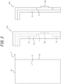
FIG. 3 is a top view illustrating an overlapping structure, a housing structure, and a fitting structure of the energy harvesting module ofFIG. 1 in a pre-assembly state; -
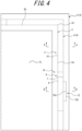
FIG. 4 is a top view illustrating the overlapping structure, the housing structure, and the fitting structure of the energy harvesting module ofFIG. 1 in an assembled state; -
FIG. 5 is a cross-sectional view at A-A ofFIG. 4 ; and -
FIG. 6 is a cross-sectional view at B-B ofFIG. 4 . - An energy harvesting module 1 and a method of producing the same according to an embodiment of the disclosure will be described in detail below with reference to the drawings.
- The energy harvesting module 1 of the present embodiment illustrated in
FIGS. 1 and 2 includes anenergy harvesting element 2, aterminal member 3, and aframe 4. Theframe 4 includes a firstpartial frame 5 and a secondpartial frame 6. Theenergy harvesting element 2 is a solar cell element that is configured to convert light energy such as sunlight or indoor light into electrical energy. Theenergy harvesting element 2 is not limited to a solar cell element, and may be, for example, a thermoelectric conversion element that is configured to convert thermal energy such as geothermal heat to electrical energy. - The
energy harvesting element 2 has a rectangular flat plate shape and includes afirst side 2a, asecond side 2b, athird side 2c, and afourth side 2d at an outer edge of theenergy harvesting element 2. Thefirst side 2a and thesecond side 2b form afirst corner 2e, thefirst side 2a and the third side2c form asecond corner 2f, thesecond side 2b and thefourth side 2d form a third corner 2g, and thethird side 2c and thefourth side 2d form afourth corner 2h. Thesecond side 2b and thethird side 2c are both located adjacently to thefirst side 2a, and thefourth side 2d is located opposite thefirst side 2a. Thefourth side 2d is provided with aterminal protrusion 2i that protrudes radially outside. Thefirst side 2a, thesecond side 2b, and thethird side 2c each have a linear shape. - The
energy harvesting element 2 includes a firstprincipal surface 2j and a secondprincipal surface 2k located at a rear side of the firstprincipal surface 2j. In the present embodiment, for convenience of explanation, a direction perpendicular to theenergy harvesting element 2, that is, the thickness direction of theenergy harvesting element 2, is referred to as vertical direction, a direction from a side corresponding to the secondprincipal surface 2k toward a side corresponding to the firstprincipal surface 2j is referred to as upward, a direction from a side corresponding to the firstprincipal surface 2j toward a side corresponding to the secondprincipal surface 2k is referred to as downward, a direction from inside to outside of the energy harvestingelement 2 in a plane perpendicular to the vertical direction is referred to as radially outside, a direction from outside to inside of the energy harvestingelement 2 in a plane perpendicular to the vertical direction is referred to as radially inside, and a direction around the energy harvestingelement 2 in a plane perpendicular to the vertical direction is referred to as perimeter direction. - The
terminal member 3 includes aterminal 3a for externally withdrawing electrical power generated by theenergy harvesting element 2. Theterminal member 3 is arranged on theterminal protrusion 2i, and is configured to be held by theframe 4 with theframe 4 being attached to the outer edge of theenergy harvesting element 2. - The outer edge of the
energy harvesting element 2 is covered by theframe 4 along the entire perimeter thereof, and is thereby protected. Theframe 4 includes a firstpartial frame 5 configured to support the outer edge of the firstprincipal surface 2j of theenergy harvesting element 2, and a secondpartial frame 6 configured to support the outer edge of the secondprincipal surface 2k of theenergy harvesting element 2. - The first
partial frame 5 and the secondpartial frame 6 are each made of a synthetic resin such as polycarbonate resin. However, the firstpartial frame 5 and the secondpartial frame 6 are not limited to those made of a synthetic resin. The firstpartial frame 5 and the secondpartial frame 6 are each integrally formed by injection molding. The firstpartial frame 5 and the secondpartial frame 6 may each be formed by assembling a plurality of members by using a fastening device such as a screw or through adhesion, fitting, or the like. The thickness of theframe 4 in the vertical direction when in an assembled state may be, for example, approximately 3 mm. - As illustrated in
FIGS. 3 to 6 , theframe 4 has anoverlapping structure 9 in which theouter perimeter wall 7 of the firstpartial frame 5 is configured to overlap with theinner perimeter wall 8 of the secondpartial frame 6 from radially outside, ahousing structure 11 in which an end of theinner perimeter wall 8 is configured to be housed in ahousing recess 10 of the firstpartial frame 5, and afitting structure 12 in which theouter perimeter wall 7 and theinner perimeter wall 8 are snap-fit with each other in the vertical direction, that is, the step-shaped portions of the partial frames are configured to be elastically deformed to move over each other in the vertical direction to thereby fit together, at thefirst side 2a of theenergy harvesting element 2. - The
outer perimeter wall 7 and theinner perimeter wall 8 each extend along the vertical direction and extend along the perimeter direction. Thehousing recess 10 is a recessed groove extending along the perimeter direction. - The
frame 4 includes, at thefirst side 2a, a supportingstructure 13 configured to have the firstpartial frame 5 support the outer edge of the firstprincipal surface 2j and the secondpartial frame 6 support the outer edge of the secondprincipal surface 2k. The supportingstructure 13 is preferably a sandwiching structure in which the firstpartial frame 5 and the secondpartial frame 6 are configured to act in conjunction to sandwich theenergy harvesting element 2 therebetween. - The supporting
structure 13 includes afirst support surface 13a provided on the firstpartial frame 5 so as to face the firstprincipal surface 2j, and asecond support surface 13b provided on the secondpartial frame 6 so as to face the secondprincipal surface 2k. - The first
partial frame 5 includes a firstprincipal wall 14 extending radially inside from the base end of theouter perimeter wall 7 and extending along the perimeter direction. On the lower surface of the firstprincipal wall 14, thehousing recess 10 is provided adjacent to theouter perimeter wall 7. Further, a part of the lower surface of the firstprincipal wall 14, the part being radially inside than thehousing recess 10, constitutes thefirst support surface 13a. - The second
partial frame 6 includes a secondprincipal wall 15 extending radially inside from the base end of theinner perimeter wall 8 and extending along the perimeter direction. The upper surface of the secondprincipal wall 15 constitutes thesecond support surface 13b. - In the
fitting structure 12, theouter perimeter wall 7 includes arecess 12a as a step-shaped portion, and theinner perimeter wall 8 includes aprotrusion 12b as a step-shaped portion. However, therecess 12a and theprotrusion 12b may be replaced with each other. That is, theouter perimeter wall 7 may include theprotrusion 12b as a step-shaped portion, and theinner perimeter wall 8 may have therecess 12a as a step-shaped portion. - In the present embodiment, the
fitting structure 12 is provided across a portion above thesecond support surface 13b and a portion below thesecond support surface 13b, thereby efficiently allocating enough size for the step-shaped portion of thefitting structure 12 and increasing the fitting strength. - In order to facilitate snap-fitting in the
fitting structure 12, a corner between an upper surface and a leading surface (outer surface) of theconvex portion 12b may be chamfered, or a corner between the lower surface and the inner surface of theouter perimeter wall 7 may be chamfered. - The
frame 4 includes, at thefirst side 2a, an alternatingarrangement structure 16 in which thehousing structure 11 and thefitting structure 12 are alternately arranged along the outer edge of theenergy harvesting element 2. That is, in the alternatingarrangement structure 16, thehousing recess 10 is provided in a portion corresponding to thehousing structure 11, but not in a portion corresponding to thefitting structure 12. Further, in the alternatingarrangement structure 16, the length of theinner perimeter wall 8 in the vertical direction of a portion corresponding to thefitting structure 12 is shorter than the length of a portion corresponding to thehousing structure 11 in the vertical direction. - In the present embodiment, in a portion corresponding to the
fitting structure 12 in the alternatingarrangement structure 16, the leading surface (upper end surface) of theinner perimeter wall 8 and the lower surface of the firstprincipal wall 14 are not in contact with each other. However, in a portion corresponding to thefitting structure 12 in the alternatingarrangement structure 16, the leading surface of theinner perimeter wall 8 and the lower surface of the firstprincipal wall 14 may be in contact with each other. In a portion corresponding to thehousing structure 11 in the alternatingarrangement structure 16, the leading surface of theinner perimeter wall 8 and the bottom surface of thehousing recess 10 may or may not be in contact with each other. - In the overlapping
structure 9, the inner surface of theouter perimeter wall 7 and the outer surface of theinner perimeter wall 8 may preferably be in contact with each other in order to enhance fitting strength. Further, in thehousing structure 11, the inner surface at the tip end of theinner perimeter wall 8 and the outer surface of thehousing recess 10 may preferably be in contact with each other in order to enhance fitting strength. - In the overlapping
structure 9, the leading surface (lower end surface) of theouter perimeter wall 7 and the base end surface (lower end surface) of theinner perimeter wall 8 are flush with each other. However, in the overlappingstructure 9, the leading surface of theouter perimeter wall 7 and the base end surface of theinner perimeter wall 8 may not be flush with each other. In the overlappingstructure 9, the inner surface of theinner perimeter wall 8 and the outer surface of theenergy harvesting element 2 may or may not be in contact with each other. - The
frame 4 includes the overlappingstructure 9, thehousing structure 11, and thefitting structure 12, not only at thefirst side 2a but also at each of thesecond side 2b, thethird side 2c, and thefourth side 2d. In addition, theframe 4 includes the alternatingarrangement structure 16 not only at thefirst side 2a but also at each of thesecond side 2b, thethird side 2c, and thefourth side 2d. - As illustrated in
FIGS. 3 to 4 , theframe 4 includes, at thefirst corner 2e, the overlappingstructure 9 and thehousing structure 11. Theframe 4 includes the overlappingstructure 9 and thehousing structure 11, also at each of thesecond corner 2f, the third corner 2g, and thefourth corner 2h. - The
frame 4 includes the supportingstructure 13 not only at thefirst side 2a, but also at each of thesecond side 2b, thethird side 2c, and thefourth side 2d. Theframe 4 includes the supportingstructure 13 also at each of thefirst corner 2e, thesecond corner 2f, the third corner 2g, and thefourth corner 2h. - The energy harvesting module 1 of the present embodiment can readily be produced through a frame attaching step of attaching the first
partial frame 5 and the secondpartial frame 6 to the outer edge of theenergy harvesting element 2 by overlapping theouter perimeter wall 7 with theinner perimeter wall 8 from radially outside, housing the end of theinner perimeter wall 8 in thehousing recess 10, and fitting in theouter perimeter wall 7 and theinner perimeter wall 8 with each other, at each of thefirst side 2a, thesecond side 2b, thethird side 2c, and thefourth side 2d. - Further, at each of the
first side 2a, thesecond side 2b, thethird side 2c, and thefourth side 2d, thehousing structure 11 prevents the firstpartial frame 5 having theouter perimeter wall 7 from relatively elastically deformed radially outside with respect to the secondpartial frame 6 having theinner perimeter wall 8, the secondpartial frame 6 having aninner perimeter wall 8, which enables to ensure, at each of thefirst side 2a, thesecond side 2b, thethird side 2c, and the fourth side, a favorable fitting strength between the firstpartial frame 5 and the secondpartial frame 6. - Further, in the energy harvesting module 1 of the present embodiment, at each of the
first corner 2e, thesecond corner 2f, the third corner 2g, and thefourth corner 2h, the overlappingstructure 9 and thehousing structure 11 prevent the firstpartial frame 5 and the secondpartial frame 6 from relatively elastically deformed radially toward both sides relative to each other, to thereby favorably retain a favorable fitting state between the firstpartial frame 5 and the secondpartial frame 6, even when the corners are subject to shock. Therefore, more favorable fitting strength can be ensured between the firstpartial frame 5 and the secondpartial frame 6. - The embodiment described above is merely an example of an embodiment of the disclosure, and various alterations can be made without departing from the gist of the disclosure.
- Accordingly, the energy harvesting module 1 and the production method thereof according to the embodiment described above can be variously modified as described below, for example.
- The energy harvesting module 1 can be variously modified as long as the energy harvesting module 1 has the
energy harvesting element 2 that is plate shaped, and theframe 4 that includes the firstpartial frame 5 configured to support the outer edge of a first principal surface of theenergy harvesting element 2 and a secondpartial frame 6 configured to support the outer edge of a second principal surface located at a rear side of the first principal surface of theenergy harvesting element 2, in which theframe 4 includes, at the first side of theenergy harvesting element 2, the overlappingstructure 9, thehousing structure 11, and thefitting structure 12, the overlappingstructure 9 being configured to have theouter perimeter wall 7 of one of the firstpartial frame 5 and the secondpartial frame 6 overlap with theinner perimeter wall 8 of the other one of the firstpartial frame 5 and the secondpartial frame 6 from radially outside, thehousing structure 11 being configured to have the end of theinner perimeter wall 8 housed in thehousing recess 10 of the one of the firstpartial frame 5 and the secondpartial frame 6, thefitting structure 12 being configured to have theouter perimeter wall 7 and theinner perimeter wall 8 fitted in with each other. - However, in the energy harvesting module 1, the
frame 4 may preferably have the overlappingstructure 9 and thehousing structure 11 for the corner (first corner 2e) of theenergy harvesting element 2. - Further, in the energy harvesting module 1, the
frame 4 may preferably have the overlappingstructure 9, thehousing structure 11, and thefitting structure 12, also at thesecond side 2b forming the corner with thefirst side 2a. - The energy harvesting module 1 may preferably have the
energy harvesting element 2 that has a rectangular plate shape, and theframe 4 may preferably have the overlappingstructure 9, thehousing structure 11, and thefitting structure 12, at each side (thefirst side 2a, thesecond side 2b, thethird side 2c, and thefourth side 2d) of theenergy harvesting element 2, and preferably have the overlappingstructure 9 and thehousing structure 11 at each corner (thefirst corner 2e, thesecond corner 2f, the third corner 2g, and thefourth corner 2h) of theenergy harvesting element 2. - Further, in the energy harvesting module 1, the
frame 4 may preferably include the supportingstructure 13 configured to have the firstpartial frame 5 support the outer edge of the firstprincipal surface 2j and the secondpartial frame 6 support the outer edge of the secondprincipal surface 2k, at least at thefirst side 2a. - Further, in the energy harvesting module 1, the supporting
structure 13 may preferably be a sandwiching structure in which the firstpartial frame 5 and the secondpartial frame 6 are configured to act in conjunction to sandwich theenergy harvesting element 2 therebetween. - Further, in the energy harvesting module 1, the
frame 4 may preferably include, at least at thefirst side 2a, the alternatingarrangement structure 16 in which thehousing structure 11 and thefitting structure 12 are alternately arranged along the outer edge of theenergy harvesting element 2. - The method for manufacturing the energy harvesting module 1 can be variously modified as long as the energy harvesting module 1 includes: the energy harvesting element 2 that is plate shaped; and the frame 4 that includes the first partial frame 5 configured to support an outer edge of the first principal surface 2j of the energy harvesting element 2, and the second partial frame 6 configured to support an outer edge of the first principal surface 2k located at a rear side of the first principal surface 2j in the energy harvesting element 2, in which the frame 4 includes, at the first side of the energy harvesting element 2, the overlapping structure 9, the housing structure 11, and the fitting structure 12, the overlapping structure 9 being configured to have an outer perimeter wall 7 of one of the first partial frame 5 and the second partial frame 6 overlap with an inner perimeter wall 8 of another one of the first partial frame 5 and the second partial frame 6 from radially outside, the housing structure 11 being configured to have an end of the inner perimeter wall 8 housed in the housing recess 10 of the one of the first partial frame 5 and the second partial frame 6, the fitting structure 12 being configured to have the outer perimeter wall 7 and the inner perimeter wall 8 fitted in with each other, the method including: a frame attachment step of attaching the first partial frame 5 and the second partial frame 6 to the outer edge of the energy harvesting element 2 by overlapping the outer perimeter wall 7 with the inner perimeter wall 8 from radially outside, housing the end of the inner perimeter wall 8 in the housing recess 10, and fitting in the outer perimeter wall 7 and the inner perimeter wall 8 with each other.
- It is possible to provide an energy harvesting module capable of simplifying production process and a method of producing the same.
-
- 1
- energy harvesting module
- 2
- energy harvesting element
- 2a
- first side
- 2b
- second side
- 2c
- third side
- 2d
- fourth side
- 2e
- first corner
- 2f
- second corner
- 2g
- third corner
- 2h
- fourth corner
- 2i
- terminal protrusion
- 2j
- first principal surface
- 2k
- second principal surface
- 3
- terminal member
- 3a
- terminal
- 4
- frame
- 5
- first partial frame
- 6
- second partial frame
- 7
- outer wall
- 8
- inner wall
- 9
- overlapping structure
- 10
- housing recess
- 11
- housing structure
- 12
- fitting structure
- 12a
- recess
- 12b
- protrusion
- 13
- supporting structure
- 13a
- first support surface
- 13b
- second support surface
- 14
- first principal wall
- 15
- second principal wall
- 16
- alternating arrangement structure.
Claims (8)
- An energy harvesting module, comprising:an energy harvesting element that is plate shaped; anda frame that includes a first partial frame configured to support an outer edge of a first principal surface of the energy harvesting element and a second partial frame configured to support an outer edge of a second principal surface located at a rear side of the first principal surface in the energy harvesting element, whereinthe frame includes, at a first side of the energy harvesting element, an overlapping structure, a housing structure, and a fitting structure, the overlapping structure being configured to have an outer perimeter wall of one of the first partial frame and the second partial frame overlap with an inner perimeter wall of another one of the first partial frame and the second partial frame from radially outside, the housing structure being configured to have an end of the inner perimeter wall housed in a housing recess of the one of the first partial frame and the second partial frame, the fitting structure being configured to have the outer perimeter wall and the inner perimeter wall fitted in with each other.
- The energy harvesting module according to claim 1, wherein the frame includes, at a corner of the energy harvesting element, the overlapping structure and the housing structure.
- The energy harvesting module according to claim 2, wherein the frame includes, also at a second side that forms the corner with the first side, the overlapping structure, the housing structure, and the fitting structure.
- The energy harvesting module according to any one of claims 1 to 3, wherein:the energy harvesting element has a rectangular plate shape; andthe frame includes, at each side of the energy harvesting element, the overlapping structure, the housing structure, and the fitting structure, and includes, also at each corner of the energy harvesting module, the overlapping structure and the housing structure.
- The energy harvesting module according to any one of claims 1 to 4, wherein the frame includes, at least at the first side, a supporting structure configured to have the first partial frame support an outer edge of the first principal surface while having the second frame support an outer edge of the second principal surface.
- The energy harvesting module according to claim 5, wherein the supporting structure is a sandwiching structure in which the first partial frame and the second partial frame are configured to act in conjunction to sandwich the energy harvesting element therebetween.
- The energy harvesting module according to any one of claims 1 to 6, wherein the frame includes, at least at the first side, an alternating arrangement structure in which the housing structure and the fitting structure are alternately arranged along the outer edge of the energy harvesting element.
- A method of producing an energy harvesting module, in which the energy harvesting module includes:an energy harvesting element that is plate shaped; anda frame that includes a first partial frame configured to support an outer edge of a first principal surface of the energy harvesting element and a second partial frame configured to support an outer edge of a second principal surface located at a rear side of the first principal surface in the energy harvesting element, whereinthe frame includes, at a first side of the energy harvesting element, an overlapping structure, a housing structure, and a fitting structure, the overlapping structure being configured to have an outer perimeter wall of one of the first partial frame and the second partial frame overlap with an inner perimeter wall of another one of the first partial frame and the second partial frame from radially outside, the housing structure being configured to have an end of the inner perimeter wall housed in a housing recess of the one of the first partial frame and the second partial frame, the fitting structure being configured to have the outer perimeter wall and the inner perimeter wall fitted in with each other,the method comprising:
a frame attachment step of attaching the first partial frame and the second partial frame to the outer edge of the energy harvesting element by overlapping the outer perimeter wall with the inner perimeter wall from radially outside, housing the end of the inner perimeter wall in the housing recess, and fitting in the outer perimeter wall and the inner perimeter wall with each other.
Applications Claiming Priority (2)
| Application Number | Priority Date | Filing Date | Title |
|---|---|---|---|
| JP2020175575 | 2020-10-19 | ||
| PCT/JP2021/035178 WO2022085367A1 (en) | 2020-10-19 | 2021-09-24 | Energy harvesting module and method for manufacturing same |
Publications (2)
| Publication Number | Publication Date |
|---|---|
| EP4231523A1 true EP4231523A1 (en) | 2023-08-23 |
| EP4231523A4 EP4231523A4 (en) | 2024-12-11 |
Family
ID=81289859
Family Applications (1)
| Application Number | Title | Priority Date | Filing Date |
|---|---|---|---|
| EP21882508.1A Withdrawn EP4231523A4 (en) | 2020-10-19 | 2021-09-24 | Energy harvesting module and method for manufacturing same |
Country Status (5)
| Country | Link |
|---|---|
| US (1) | US20230402962A1 (en) |
| EP (1) | EP4231523A4 (en) |
| JP (1) | JPWO2022085367A1 (en) |
| CN (1) | CN116325485A (en) |
| WO (1) | WO2022085367A1 (en) |
Family Cites Families (10)
| Publication number | Priority date | Publication date | Assignee | Title |
|---|---|---|---|---|
| JPH08148710A (en) * | 1994-11-17 | 1996-06-07 | Daido Hoxan Inc | Method for engaging metal frame with outer edge of solar module panel |
| DE20209218U1 (en) * | 2002-06-07 | 2002-10-24 | Conergy-Systems GmbH, 15827 Dahlewitz | Attachment for a solar module (snap-in - assembly module) |
| DE102008031545A1 (en) * | 2008-07-07 | 2010-01-14 | Tesa Se | Frame for a plate-shaped solar element |
| JP4883114B2 (en) * | 2009-03-10 | 2012-02-22 | 三菱電機株式会社 | Solar cell module |
| CN102881753B (en) * | 2012-09-25 | 2015-02-25 | 天津英利新能源有限公司 | Photovoltaic module frame and assembling method thereof |
| CN103208543B (en) * | 2013-03-22 | 2015-08-05 | 友达光电股份有限公司 | solar module |
| CN103247704B (en) * | 2013-05-31 | 2016-02-10 | 英利能源(中国)有限公司 | The method for packing of solar cell frame and solar panel |
| JP2015047351A (en) * | 2013-09-02 | 2015-03-16 | 株式会社馬印 | Display tool |
| CN108878561A (en) * | 2017-05-16 | 2018-11-23 | 苏州阿特斯阳光能源科技有限公司 | Double glass photovoltaic modulies |
| JP7694567B2 (en) * | 2020-07-22 | 2025-06-18 | 日本ゼオン株式会社 | Energy harvesting module and manufacturing method thereof |
-
2021
- 2021-09-24 WO PCT/JP2021/035178 patent/WO2022085367A1/en not_active Ceased
- 2021-09-24 US US18/247,746 patent/US20230402962A1/en not_active Abandoned
- 2021-09-24 EP EP21882508.1A patent/EP4231523A4/en not_active Withdrawn
- 2021-09-24 JP JP2022557328A patent/JPWO2022085367A1/ja active Pending
- 2021-09-24 CN CN202180068370.7A patent/CN116325485A/en active Pending
Also Published As
| Publication number | Publication date |
|---|---|
| WO2022085367A1 (en) | 2022-04-28 |
| EP4231523A4 (en) | 2024-12-11 |
| CN116325485A (en) | 2023-06-23 |
| JPWO2022085367A1 (en) | 2022-04-28 |
| US20230402962A1 (en) | 2023-12-14 |
Similar Documents
| Publication | Publication Date | Title |
|---|---|---|
| KR101044302B1 (en) | Battery Cell Assembly and Assembly Method of Battery Cell Assembly | |
| US20110155127A1 (en) | Frame for solar module | |
| KR101086467B1 (en) | Architectural panel integrated solar cell module | |
| WO2009119774A1 (en) | Solar cell module | |
| JP4699060B2 (en) | Terminal box device for solar cell module | |
| CN112367028A (en) | Photovoltaic module frame, photovoltaic support assembly and photovoltaic module | |
| EP4231523A1 (en) | Energy harvesting module and method for manufacturing same | |
| EP4187778A1 (en) | Energy harvesting module and method for manufacturing same | |
| JPH104207A (en) | Solar cell module, manufacturing method and mounting structure thereof, and roof with solar cell module | |
| KR101138514B1 (en) | LED Lamp | |
| JP7408811B2 (en) | Louver assembly to which solar panels can be attached | |
| JP2019209957A (en) | Fender structure with solar power generation function | |
| JP2023028061A (en) | Building finishing material solar module assembly | |
| US9906186B2 (en) | Holding frame and solar cell module | |
| KR102665054B1 (en) | Louver assembly | |
| KR102864670B1 (en) | All-in-one solar panel for easy maintenance | |
| CN217787578U (en) | Top cover assembly and projector | |
| KR101357200B1 (en) | Thin concentrator photovoltaic module | |
| CN223391299U (en) | Corner fitting component, photovoltaic module thereof and photovoltaic system | |
| CN110998867B (en) | Concentrating photovoltaic module, concentrating photovoltaic panel, and concentrating photovoltaic device | |
| JP2004146765A (en) | Solar array | |
| US10563848B2 (en) | Backlight module and display apparatus | |
| KR20110041095A (en) | Solar cell module | |
| CN210270491U (en) | Ultrathin projector | |
| JPH0645354U (en) | Solar cell module and solar cell device connecting them |
Legal Events
| Date | Code | Title | Description |
|---|---|---|---|
| STAA | Information on the status of an ep patent application or granted ep patent |
Free format text: STATUS: THE INTERNATIONAL PUBLICATION HAS BEEN MADE |
|
| PUAI | Public reference made under article 153(3) epc to a published international application that has entered the european phase |
Free format text: ORIGINAL CODE: 0009012 |
|
| STAA | Information on the status of an ep patent application or granted ep patent |
Free format text: STATUS: REQUEST FOR EXAMINATION WAS MADE |
|
| 17P | Request for examination filed |
Effective date: 20230411 |
|
| AK | Designated contracting states |
Kind code of ref document: A1 Designated state(s): AL AT BE BG CH CY CZ DE DK EE ES FI FR GB GR HR HU IE IS IT LI LT LU LV MC MK MT NL NO PL PT RO RS SE SI SK SM TR |
|
| DAV | Request for validation of the european patent (deleted) | ||
| DAX | Request for extension of the european patent (deleted) | ||
| A4 | Supplementary search report drawn up and despatched |
Effective date: 20241112 |
|
| RIC1 | Information provided on ipc code assigned before grant |
Ipc: F24S 25/20 20180101ALI20241106BHEP Ipc: H02S 30/10 20140101AFI20241106BHEP |
|
| STAA | Information on the status of an ep patent application or granted ep patent |
Free format text: STATUS: EXAMINATION IS IN PROGRESS |
|
| 17Q | First examination report despatched |
Effective date: 20250527 |
|
| STAA | Information on the status of an ep patent application or granted ep patent |
Free format text: STATUS: THE APPLICATION HAS BEEN WITHDRAWN |
|
| 18W | Application withdrawn |
Effective date: 20250623 |