EP4231497A1 - Wireless power-feeding apparatus - Google Patents
Wireless power-feeding apparatus Download PDFInfo
- Publication number
- EP4231497A1 EP4231497A1 EP21879679.5A EP21879679A EP4231497A1 EP 4231497 A1 EP4231497 A1 EP 4231497A1 EP 21879679 A EP21879679 A EP 21879679A EP 4231497 A1 EP4231497 A1 EP 4231497A1
- Authority
- EP
- European Patent Office
- Prior art keywords
- protrusions
- pair
- rail
- width direction
- electrodes
- Prior art date
- Legal status (The legal status is an assumption and is not a legal conclusion. Google has not performed a legal analysis and makes no representation as to the accuracy of the status listed.)
- Pending
Links
Images


Classifications
-
- H—ELECTRICITY
- H02—GENERATION; CONVERSION OR DISTRIBUTION OF ELECTRIC POWER
- H02J—ELECTRIC POWER NETWORKS; CIRCUIT ARRANGEMENTS OR SYSTEMS FOR SUPPLYING OR DISTRIBUTING ELECTRIC POWER; SYSTEMS FOR STORING ELECTRIC ENERGY
- H02J50/00—Circuit arrangements or systems for wireless supply or distribution of electric power
- H02J50/05—Circuit arrangements or systems for wireless supply or distribution of electric power using capacitive coupling
Definitions
- the present disclosure relates to a wireless power-feeding apparatus that wirelessly feeds electric power to an electronic device supported by a rail.
- Patent Document 1 discloses a system in which an energy transmission interface is disposed in a U-shaped free space of a hat-shaped mounting rail having a U-shaped base. In this system, power is wirelessly fed from an energy transmission interface to a bus subscriber module installed on the hat-shaped mounting rail.
- the electric field coupling system is a system in which electrodes are provided on the power transmission side and the power reception side respectively, and electric power is transmitted using an electric field generated when these electrodes approach each other.
- Patent Document 1 JP 5928495 B2
- the energy transmission interface serves as an electrode on the power transmission side, and an electrode on the power reception side is provided to the bus subscriber module.
- the arrangement area of the energy transmission interface is limited to the U-shaped free space of the hat-shaped mounting rail. Therefore, it is difficult to widen the width of the electrode on the power transmission side. Accordingly, it is difficult to feed large power to the bus subscriber module.
- an object of the present disclosure is to solve the above-described problem, and to provide a wireless power-feeding apparatus capable of securing a wider width of an electrode for wirelessly feeding electric power to an electronic device supported by a rail by means of an electric field coupling system, compared with a configuration in which the electrode is disposed in the rail.
- a wireless power-feeding apparatus includes:
- the two electrodes extend along a longitudinal direction of the rail, and are disposed so as to sandwich the rail in a width direction of the rail.
- the width of an electrode for wirelessly feeding electric power to an electronic device supported by a rail by means of an electric field coupling system can be secured wider than that in a configuration in which the electrode is disposed in the rail.
- a wireless power-feeding apparatus includes:
- the electrodes are disposed outside the rail. Therefore, the electrodes can be enlarged without being limited by the size and the shape of the rail.
- the two electrodes are disposed opposite to each other across the rail. Therefore, the possibility that the two electrodes interfere with each other can be reduced.
- a holding member for holding the two electrodes may be further provided. According to this configuration, since the holding member holds the two electrodes, the arrangement positions of the two electrodes can be stabilized.
- the holding member may include a main body portion, and a pair of first protrusions and a pair of second protrusions.
- the pair of first protrusions and the pair of second protrusions protrude outward from the main body portion in the width direction, are provided corresponding to the two electrodes respectively, and face each other in a thickness direction of the rail intersecting the width direction and the longitudinal direction.
- One of the two electrodes may be sandwiched between one of the pair of first protrusions and one of the pair of second protrusions, and the other of the two electrodes may be sandwiched between the other of the pair of first protrusions and the other of the pair of second protrusions. According to this configuration, each electrode can be held between each of the first protrusions and each of the second protrusions.
- Each of the pair of first protrusions may include a projection protruding toward each of the second protrusions at the tip of each of the pair of first protrusions.
- the projections may restrict the respective two electrodes, sandwiched by the pair of first protrusions and the pair of second protrusions, from coming out of the spaces between the pair of first protrusions and the pair of second protrusions. According to this configuration, it is possible to prevent each electrode from coming out of the space between each of the first protrusions and each of the second protrusions.
- Each of the projections may have an inclined surface inclined with respect to the pair of second protrusions toward the outside of the main body portion.
- the holding member may include an engagement portion engageable with the rail. According to this configuration, the holding member is held by the rail by the engagement of the engagement portion with the rail.
- the rail may include a bottom portion, a pair of side portions protruding in the thickness direction of the rail intersecting the width direction and the longitudinal direction, from both ends of the bottom portion in the width direction, and a pair of flange portions each protruding in the width direction from each of the pair of side portions toward the outside thereof.
- the engagement portion may hold the pair of flange portions from both sides in the thickness direction of the rail. According to this configuration, the configuration of the engagement portion can be a simple configuration that sandwiches the flange portions of the rail.
- the holding member may be provided to the electronic device. According to this configuration, a space for disposing the holding member and a space for disposing the electronic device can be shared. Therefore, the space for disposing the holding member and the electronic device can be saved.
- the rail is a DIN rail.
- FIG. 1 is a plan view of a wireless power-feeding apparatus according to a first embodiment of the present disclosure.
- FIG. 2 is a cross-sectional view taken along line A-A in FIG. 1 .
- the wireless power-feeding apparatus 10 wirelessly feeds an electrode to an electronic device 50 attached to a DIN rail 20.
- the wireless power-feeding apparatus 10 includes the DIN rail 20, an electrode 30, and a holding member 40.
- the DIN rail 20 is produced according to the German Industrial Standard (DIN).
- the DIN rail 20 is attached to a wall 60.
- the electronic device 50 can be attached to the DIN rail 20 as described later.
- the DIN rail 20 is an example of a rail.
- the DIN rail 20 extends in a longitudinal direction 2.
- the length of the DIN rail 20 in a width direction 3 is shorter than the length of the DIN rail 20 in the longitudinal direction 2.
- the width direction 3 of the DIN rail 20 is orthogonal to the longitudinal direction 2 of the DIN rail 20 in a plan view.
- the length of the DIN rail 20 in a thickness direction 4 is shorter than the length of the DIN rail 20 in the width direction 3.
- the thickness direction 4 of the DIN rail 20 is orthogonal to the longitudinal direction 2 of the DIN rail 20 and the width direction 3 of the DIN rail 20.
- a cross section of the DIN rail 20 has a substantially U-shape.
- the longitudinal direction of the DIN rail 20 is defined as the longitudinal direction 2
- the width direction of the DIN rail 20 is defined as the width direction 3
- the thickness direction of the DIN rail 20 is defined as the thickness direction 4.
- the DIN rail 20 includes a bottom portion 21, a pair of side portions 22A and 22B, and a pair of flange portions 23A and 23B.
- the DIN rail 20 is formed in a shape having a substantially U-shaped cross section as shown in FIG. 2 with the plate-shaped member being bent.
- the bottom portion 21 extends in the longitudinal direction 2 and the width direction 3.
- the pair of side portions 22A and 22B protrude in the thickness direction 4 from both ends in the width direction 3 of the bottom portion 21. That is, the pair of side portions 22A and 22B and the bottom portion 21 are orthogonal to each other.
- the side portion 22A protrudes from one end in the width direction 3 of the bottom portion 21.
- the side portion 22B protrudes from the other end in the width direction 3 of the bottom portion 21.
- the pair of flange portions 23A and 23B protrude in the width direction 3 from the tips of the pair of side portions 22A and 22B toward the outside of the pair of side portions 22A and 22B, respectively. That is, the side portions 22A and 22B protrude in directions opposite to each other.
- the flange portion 23A and the side portion 22A are orthogonal to each other, and the flange portion 23B and the side portion 22B are orthogonal to each other.
- a plurality of through holes are formed in the bottom portion 21.
- the DIN rail 20 is attached to a wall surface 60a of the wall 60 as illustrated in FIG. 2 .
- the bottom portion 21 is in contact with the wall surface 60a, and the pair of side portions 22A and 22B protrude from the wall surface 60a in the thickness direction 4.
- the DIN rail 20 can support at least one electronic device 50.
- two electronic devices 50 are supported by the DIN rail 20.
- the electronic device 50 is, for example, a power feeding device, a temperature control device, a sensor unit, a communication unit, a terminal block, or the like.
- Each electronic device 50 includes a groove engageable with the DIN rail 20. The groove engages with the pair of side portions 22A and 22B and the pair of flange portions 23A and 23B, whereby the electronic device 50 is supported by the DIN rail 20.
- the electrode 30 is a plate-like member made of a conductor such as copper or aluminum. As shown in FIG. 1 , the length of the electrode 30 in the longitudinal direction 2 is longer than the length of the electrode 30 in the width direction 3. That is, the electrode 30 extends along the longitudinal direction 2. As shown in FIG. 2 , the length of the electrode 30 in the thickness direction 4 is shorter than the length of the electrode 30 in the width direction 3.
- the shape of the electrode 30 is not limited to the plate shape as described above, and may be, for example, a cylindrical shape or the like.
- the wireless power-feeding apparatus 10 includes two electrodes 30A and 30B as the electrode 30.
- the two electrodes 30A and 30B are arranged at an interval in the width direction 3.
- the DIN rail 20 is positioned between the two electrodes 30A and 30B. That is, the two electrodes 30A and 30B are arranged so as to sandwich the DIN rail 20 in the width direction 3.
- the electrode 30A is disposed on the side of the side portion 22A and the flange portion 23A, of the pair of side portions 22A and 22B and the pair of flange portions 23A and 23B.
- the electrode 30B is disposed on the side of the side portion 22B and the flange portion 23B, of the pair of side portions 22A and 22B and the pair of flange portions 23A and 23B.
- FIG. 3 is a circuit diagram of an equivalent circuit of the wireless power-feeding apparatus 10 according to the first embodiment of the present disclosure.
- the electrodes 30A and 30B of the wireless power-feeding apparatus 10 wirelessly feed the electrodes to the electronic device 50 supported by the DIN rail 20 by means of the electric field coupling system.
- the electronic device 50 includes two electrodes 51A and 51B.
- the electrodes 51A and 51B are electrically connected via a load 52.
- the load 52 is a device that converts a flowing current into heat or the like, and is, for example, a circuit having various electronic components such as a resistor, a capacitor, an inductor, and a transistor.
- the electrode 51A of the electronic device 50 faces the electrode 30A of the wireless power-feeding apparatus 10
- the electrode 51B of the electronic device 50 faces the electrode 30B of the wireless power-feeding apparatus 10.
- the electrodes 30A and 30B of the wireless power-feeding apparatus 10 are electrically connected via an AC power supply 70.
- a DC power supply may be provided, and the DC power supply and the electrodes 30A and 30B may be electrically connected via a D/A converter.
- the electrodes 30A and 51A facing each other and the electrodes 30B and 51B facing each other function as capacitors respectively.
- the AC power supply 70 When the AC power supply 70 is operated, a high-frequency current flows through the capacitor. As a result, electric power is wirelessly fed from the electrodes 30A and 30B to the electronic device 50.
- the holding member 40 holds the two electrodes 30A and 30B.
- the cross section of the holding member 40 has a substantially U-shape.
- the holding member 40 includes a base portion 41, a pair of side portions 42A and 42B, a pair of protrusions 43A and 43B, a pair of protrusions 44A and 44B, and a pair of protrusions 45A and 45B.
- the base portion 41 has a rectangular parallelepiped shape.
- the length of the base portion 41 in the longitudinal direction 2 is shorter than the length of the base portion 41 in the width direction 3.
- the length of the base portion 41 in the thickness direction 4 is shorter than the length of the base portion 41 in the longitudinal direction 2 and shorter than the length of the base portion 41 in the width direction 3.
- the pair of side portions 42A and 42B protrude in the thickness direction 4 from both ends in the width direction 3 of the base portion 41.
- the side portion 42A protrudes from one end in the width direction 3 of the base portion 41.
- the side portion 42B protrudes from the other end in the width direction 3 of the base portion 41.
- the base portion 41 and the pair of side portions 42A and 42B are examples of the main body portion.
- the pair of protrusions 43A and 43B protrude inward in the width direction 3 from the tips of the pair of side portions 41A and 42B, respectively. That is, the pair of protrusions 43A and 43B protrude in directions opposite to each other.
- the protrusion 43A protrudes from the tip of the side portion 42A.
- the protrusion 43B protrudes from the tip of the side portion 42B.
- the protrusions 43A and 43B face a surface 41a of the base portion 41 in the width direction 3.
- a surface 43Ba of the protrusion 43B is inclined with respect to the width direction 3.
- the surface 43Ba is a surface facing outward in the thickness direction 4 of the holding member 40.
- the surface 43Ba extends outward in the width direction 4 of the holding member 40 as it goes outward in the thickness direction 3 of the holding member 40.
- the pair of protrusions 44A and 44B protrude outward in the width direction 3 from the tips of the pair of side portions 42A and 42B, respectively. That is, the pair of protrusions 44A and 44B protrude in directions opposite to each other.
- the protrusion 44A protrudes from the tip of the side portion 42A.
- the protrusion 44B protrudes from the tip of the side portion 42B.
- the pair of protrusions 44A and 44B is an example of a pair of second protrusions.
- the pair of protrusions 45A and 45B protrude outward in the width direction 3 from the pair of side portions 42A and 42B, respectively. That is, the pair of protrusions 45A and 45B protrude in directions opposite to each other.
- the protrusion 45A protrudes from the side portion 42A.
- the protrusion 45A is located on the proximal end side of the side portion 41A with respect to the protrusion 44A.
- the protrusion 45A faces the protrusion 44A in the thickness direction 4.
- the protrusion 45B protrudes from the side portion 42B.
- the protrusion 45B is located on the proximal end side of the side portion 41B with respect to the protrusion 44B.
- the protrusion 45B faces the protrusion 44B in the thickness direction 4.
- the pair of protrusions 45A and 45B is an example of a pair of first protrusions.
- the protrusion 44A and the protrusion 45A have the same length in the width direction 3.
- the protrusion 44A and the protrusion 45A may have different lengths in the width direction 3.
- the protrusion 44B and the protrusion 45B have the same length in the width direction 3, but may have different lengths in the width direction 3.
- the protrusion 45A includes a projection 46A.
- the projection 46A is provided at the tip of the protrusion 45A.
- the projection 46A protrudes in the thickness direction 4 from the protrusion 45A toward the protrusion 44A.
- the protrusion 45B includes a projection 46B.
- the projection 46B is provided at the tip of the protrusion 45B.
- the projection 46B protrudes in the thickness direction 4 from the protrusion 45B toward the protrusion 44B.
- the projection 46A includes a surface 46Aa facing outward in the width direction 3.
- the surface 46Aa is a surface facing outward in the width direction 3 of the holding member 40.
- the surface 46Aa is inclined with respect to the width direction 3.
- the surface 46Aa extends so as to approach the protrusion 44A as it goes closer to the inside in the width direction 3 of the holding member 40. That is, the surface 46Aa is inclined with respect to the protrusion 44A toward the outside of the side portion 42A.
- the projection 46B includes a surface 46Ba facing outward in the width direction 3.
- the surface 46Ba is a surface facing outward in the width direction 3 of the holding member 40.
- the surface 46Ba is inclined with respect to the width direction 3.
- the surface 46Ba extends so as to approach the protrusion 44B as it goes closer to the inside in the width direction 3 of the holding member 40. That is, the surface 46Ba is inclined with respect to the protrusion 44B toward the outside of the side portion 42B.
- the surfaces 46Aa and 46Ba are examples of inclined surfaces.
- the procedure is generally as follows. First, the DIN rail 20 is attached to the wall surface 60a of the wall 60. Then, the holding member 40 is engaged with the DIN rail 20, whereby the holding member 40 is supported by the DIN rail 20. Then, the electrodes 30A and 30B are inserted into the holding member 40, whereby the electrodes 30A and 30B are held by the holding member 40. Note that the procedure through which the holding member 40 is supported by the DIN rail 20 and the electrodes 30A and 30B are held by the holding member 40 may be different from that described above. For example, the holding member 40 may be engaged with the DIN rail 20 after the electrodes 30A and 30B are held by the holding member 40.
- the holding member 40 engages with the DIN rail 20 and is supported by the DIN rail 20.
- the DIN rail 20 supports the holding member 40 in a state of being inserted between the pair of side portions 42A and 42B of the holding member 40.
- the back side of a space 42a between the pair of side portions 42A and 42B (the side of the surface 41a of the base portion 41) is wider than the front side of the space 42a. This is because the pair of protrusions 43A and 43B are present at the front side of the space 42a.
- the length in the width direction 3 between the pair of protrusions 43A and 43B (the length in the width direction 3 at the front side of the space 42a) is substantially the same as the length in the width direction 3 from the outer surface of the side portion 22A to the outer surface of the side portion 22B of the DIN rail 20.
- the length in the width direction 3 at the back side of the space 40a is a length including the length in the width direction 3 of the gap 40b. That is, the length in the width direction 3 at the back side of the space 40a is the length in the width direction between the pair of side portions 42A and 42B.
- the length in the width direction 3 at the back side of the space 40a is substantially the same as the length in the width direction 3 from the tip of the flange portion 23A to the tip of the flange portion 23B of the DIN rail 20.
- the bottom portion 21 and the pair of side portions 22A and 22B of the DIN rail 20 are positioned between the pair of protrusions 43A and 43B.
- the flange portions 23A and 23B of the DIN rail 20 are inserted into the respective gaps 40b between the surface 41a and the protrusions 43A and 43B.
- the surface 41a of the base portion 41 and the protrusions 43A and 43B sandwich the flange portions 23A and 23B from both sides in the thickness direction 4. That is, the surface 41a of the base portion 41 of the holding member 40 and the protrusions 43A and 43B are engaged with the flange portions 23A and 23B of the DIN rail 20.
- the holding member 40 is supported by the DIN rail 20.
- the surface 41a of the base portion 41 of the holding member 40 and the protrusions 43A and 43B are examples of engagement portions.
- the holding member 40 In the process of being supported by the DIN rail 20, the holding member 40 is brought close to the flange portions 23A and 23B of the DIN rail 20 along the thickness direction 4. At this time, the surface 43Ba of the protrusion 43B of the holding member 40 comes into contact with the flange portion 23B. Then, a reaction force acts on the surface 43Ba from the flange portion 23B. Since the surface 43Ba is inclined with respect to the width direction 3, a part of the reaction force is a force that pushes the protrusion 43B outward in the width direction 3. Therefore, the protrusion 43B is bent outward in the width direction 3.
- the length in the width direction 3 between the pair of protrusions 43A and 43B becomes longer, so that the flange portions 23A and 23B pass through the front side of the space 40a and reach the back side of the space 40a.
- the flange portions 23A and 23B are inserted into the respective gaps 40b between the surface 41a and the protrusions 43A and 43B, and the holding member 40 is supported by the DIN rail 20.
- the holding member 40 holds the two electrodes 30A and 30B.
- a gap 40c is formed between the protrusions 44A and 45A of the holding member 40.
- the length of the gap 40c in the thickness direction 4 is substantially the same as the length of the electrode 30A in the thickness direction 4.
- a gap 40d is formed between the protrusions 44B and 45B of the holding member 40.
- the length of the gap 40d in the thickness direction 4 is substantially the same as the length of the electrode 30B in the thickness direction 4.
- the electrode 30A is sandwiched between the protrusions 44A and 45A
- the electrode 30B is sandwiched between the protrusions 44B and 45B.
- the holding member 40 includes the protrusions 44A and 45A that hold the electrode 30A and the protrusions 44B and 45B that hold the electrode 30B.
- the holding member 40 includes the protrusions 44A and 45A facing each other in the thickness direction 4 corresponding to the electrode 30A, and includes the protrusions 44B and 45B facing each other in the thickness direction 4 corresponding to the electrode 30B
- the electrode 30A is brought close to the tips of the protrusions 44A and 45A from the outside in the width direction 3 of the holding member 40 along the width direction 3.
- the projection 46A is provided at the tip of the protrusion 45A.
- the length in the thickness direction 4 between the protrusions 44A and 45A is shorter than the length in the thickness direction 4 of the electrode 30A. Therefore, the electrode 30A comes into contact with and presses the surface 46Aa of the projection 46A provided to the protrusion 45A.
- a part of the pressing force acting on the surface 46Aa is a force for bending the protrusion 45A in the thickness direction 4 so as to be away from the protrusion 44A.
- the electrode 30A passes through the projection 46A and is inserted between the protrusions 44A and 45A.
- the electrode 30A is sandwiched between the protrusions 44A and 45A, and is supported by the holding member 40. In this state, the projection 46A restricts the electrode 30A from falling off from the space between the protrusions 44A and 45A.
- the electrode 30B is brought close to the tips of the protrusions 44B and 45B along the width direction 3 in the same manner as the electrode 30A.
- the electrode 30B presses the surface 46Ba of the projection 46B provided at the tip of the protrusion 45B, thereby increasing the space between the protrusions 44B and 45B.
- the electrode 30B passes through the projection 46B, is sandwiched between the protrusions 44B and 45B, and is supported by the holding member 40. In this state, the projection 46B restricts the electrode 30B from falling off from the space between the protrusions 44B and 45B.
- the electrodes 30A and 30B are disposed outside the DIN rail 20. Therefore, the electrodes 30 A and 30B can be enlarged without being limited by the size and the shape of the DIN rail 20.
- the two electrodes 30A and 30B are disposed opposite to each other across the DIN rail 20. Therefore, the possibility that the two electrodes 30A and 30B interfere with each other can be reduced.
- the holding member 40 since the holding member 40 holds the two electrodes 30A and 30B, the arrangement positions of the two electrodes 30A and 30B can be stabilized.
- the two electrodes 30A and 30B can be held between the protrusions 44A and 45A and between the protrusions 44B and 45B, respectively.
- the projections 46A and 46B can prevent the electrode 30A from coming out of the space between the protrusions 44A and 45A and prevent the electrode 30B from coming out of the space between the protrusions 44B and 45B.
- the electrode 30A when the electrode 30A is inserted between the protrusions 44A and 45A, the electrode 30A presses the surface 46Aa of the projection 46A, so that a force in a direction away from the protrusion 44A acts on the protrusion 45A. As a result, the protrusion 45A bends, and the space between the protrusions 44A and 45A increases.
- the electrode 30B when the electrode 30B is inserted between the protrusions 44B and 45B, the electrode 30B presses the surface 46Ba of the projection 46B, so that a force in a direction away from the protrusion 44B acts on the protrusion 45B.
- the protrusion 45B bends, and the space between the protrusions 44B and 45B increases.
- the electrode 30A can be easily inserted between the protrusions 44A and 45A.
- the electrode 30B can be easily inserted between the protrusions 44B and 45B.
- the protrusion 43A and the surface 41a of the base portion 41 are engaged with the flange portion 23A of the DIN rail 20, and the protrusion 43B and the surface 41a of the base portion 41 are engaged with the flange portion 23B of the DIN rail 20, whereby the holding member 40 is held by the DIN rail 20.
- the holding member 40 and the DIN rail 20 can be engaged with each other with a simple configuration in which the flange portions 23A and 23B are sandwiched between the pair of protrusions 43A and 43B and the surface 41a of the base portion 41.
- the projections 46A and 45B are provided on the protrusions 45A and 45B, respectively.
- the projections 46A and 46B may be provided on the protrusions 44A and 44B, respectively.
- the pair of protrusions 44A and 44B corresponds to the pair of second protrusions
- the pair of protrusions 45A and 45B corresponds to the pair of first protrusions.
- the projections 46A and 46B may be provided on both the protrusions 45A and 45B and the protrusions 44A and 44B.
- the protrusion 43B has the surface 43Ba inclined with respect to the width direction 3.
- the protrusion 43A may have a surface inclined with respect to the width direction 3.
- both the protrusions 43A and 43B may have surfaces inclined with respect to the width direction 3.
- the DIN rail 20 corresponds to a rail.
- the rail is not limited to the DIN rail 20 as long as the rail can be attached with the electronic device 50.
- the rail may be a member in which a plurality of members (for example, a member corresponding to the bottom portion 21 and a member corresponding to the pair of side portions 22A and 22B) are combined to form a rail shape.
- the member corresponding to the pair of side portions 22A and 22B of the rail may be inclined with respect to the member corresponding to the bottom portion 21.
- the member corresponding to the pair of side portions 22A and 22B of the rail may extend from the member corresponding to the bottom portion 21 not in the thickness direction 4 orthogonal to the longitudinal direction 2 and the width direction 3 but along the thickness direction not orthogonal to but intersecting the longitudinal direction 2 and the width direction 3.
- the shape of the holding member 40 is not limited to the shape illustrated in FIGS. 1 and 2 on the condition that the two electrodes 30A and 30B can be held.
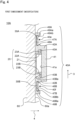
- FIG. 4 is a diagram of a wireless power-feeding apparatus according to a modification of the first embodiment of the present disclosure, corresponding to the A-A cross section in FIG. 1 .
- a configuration of a wireless power-feeding apparatus 10A according to a modification of the first embodiment will be described with reference to FIG. 4 .
- differences from the wireless power-feeding apparatus 10 illustrated in FIGS. 1 and 2 will be described.
- common points with the wireless power-feeding apparatus 10 illustrated in FIGS. 1 and 2 are denoted by the same reference numerals, and description thereof will be omitted. The same applies to the second embodiment and the third embodiment described later.
- a holding member 40A of the wireless power-feeding apparatus 10A illustrated in FIG. 4 includes a pair of protrusions 47A and 47B and a pair of protrusions 48A and 48B, instead of the pair of protrusions 44A and 44B and the pair of protrusions 45A and 45B.
- the pair of protrusions 47A and 47B and the pair of protrusions 48A and 48B protrude outward in the width direction 3 from the pair of side portions 42A and 42B, respectively.
- the protrusion 47A is located on the proximal end side of the side portion 42A with respect to the protrusion 48A.
- the protrusion 47B is located on the proximal end side of the side portion 42B with respect to the protrusion 48B.
- Bent portions 49A and 49B are formed at the tips of the pair of protrusions 47A and 47B.
- the bent portion 49A faces the protrusion 48A in the width direction 3.
- the bent portion 49B faces the protrusion 48B in the width direction 3.
- a projection 49Aa is formed at the tip of the bent portion 49A, and a projection 49Ba is formed at the tip of the bent portion 49B.
- the projection 49Aa protrudes toward the protrusion 48A, and the projection 49Ba protrudes toward the protrusion 48B.
- the electrode 30A is held in a space 40e between the projection 49Aa and the protrusion 48A and the protrusion 47A
- the electrode 30B is held in a space 40f between the projection 49Ba and the protrusion 48B and the protrusion 47B.
- the gap 40c between the protrusions 44A and 45A (space into which the electrode 30A is inserted) and the gap 40d between the protrusions 44B and 45B (space into which the electrode 30B is inserted) are open in the width direction 3.
- a projection 49Aa includes a surface 49Ab facing the protrusion 48A.
- the surface 49Ab is inclined with respect to the thickness direction 4.
- a projection 49Ba includes a surface 49Bb facing the protrusion 48B.
- the surface 49Bb is inclined with respect to the thickness direction 4.
- the electrodes 30A and 30B are brought close to the surfaces 49Ab and 49Bb of the projections 49Aa and 49Ba along the thickness direction 4.
- the electrodes 30A and 30B come into contact with and press the surfaces 49Ab and 49Bb.
- the bent portions 49A and 49B are bent, and the space between the projection 49Aa and the protrusion 48A and the space between the projection 49Ba and the protrusion 48B are widened, respectively.
- the electrode 30A is held in the space 40e by the projection 49Aa, the protrusion 48A, and the protrusion 47A
- the electrode 30B is held in the space 40f by the projection 49Ba, the protrusion 48B, and the protrusion 47B.
- FIG. 5 is a plan view of a wireless power-feeding apparatus according to a second embodiment of the present disclosure.
- FIG. 6 is a cross-sectional view taken along line B-B in FIG. 5 .
- a wireless power-feeding apparatus 10B according to the second embodiment is different from the wireless power-feeding apparatus 10 according to the first embodiment in that the wireless power-feeding apparatus 10B according to the second embodiment does not include the holding member 40.
- the electrodes 30A and 30B are attached to the wall surface 60a of the wall 60 as illustrated in FIG. 6 .
- Various known configurations are adopted as the configuration in which the electrodes 30A and 30B are attached to the wall surface 60a.
- a plurality of through holes may be formed in the electrodes 30A and 30B. By inserting screws or the like into the through holes, the electrodes 30A and 30B can be attached to the wall surface 60a.
- the electrodes 30A and 30B may be attached to the wall surface 60a by a known means such as fitting.
- FIG. 7 is a plan view of a wireless power-feeding apparatus according to a third embodiment of the present disclosure.
- FIG. 8 is a cross-sectional view taken along line C-C in FIG. 7 .
- a wireless power-feeding apparatus 10C according to the third embodiment is different from the wireless power-feeding apparatus 10 according to the first embodiment in that the wireless power-feeding apparatus 10C includes a holding member 40B that holds the electrodes 30A and 30B, and the holding member 40B is provided to the electronic device 50.
- the pair of side portions 42A and 42B of the holding member 40B protrude in the width direction 3 from a surface 50a of the electronic device 50. That is, in the third embodiment, the electronic device 50 also functions as a main body of the holding member.
- the holding member 40B of the wireless power-feeding apparatus 10C of the third embodiment includes the pair of protrusions 43A and 43B, the pair of protrusions 44A and 44B, and the pair of protrusions 45A and 45B, in addition to the pair of side portions 42A and 42B.
- the pair of protrusions 43A and 43B and the surface 50a of the electronic device 50 are engaged with the flange portions 23A and 23B of the DIN rail 20.
- the protrusions 44A and 45A sandwich the electrode 30A
- the protrusions 44B and 45B sandwich the electrode 30B.
- the electronic device 50 is supported by the DIN rail 20, and the holding member 40B provided to the electronic device 50 holds 30A and 30B.
- the space for disposing the holding member 40B and the space for disposing the electronic device 50 can be shared. Therefore, the space for disposing the holding member 40B and the electronic device 50 can be saved.
Landscapes
- Engineering & Computer Science (AREA)
- Computer Networks & Wireless Communication (AREA)
- Power Engineering (AREA)
- Mounting Components In General For Electric Apparatus (AREA)
Abstract
Description
- The present disclosure relates to a wireless power-feeding apparatus that wirelessly feeds electric power to an electronic device supported by a rail.
- A wireless power-feeding apparatus that wirelessly feeds electric power to an electronic device supported by a rail is known. For example, Patent Document 1 discloses a system in which an energy transmission interface is disposed in a U-shaped free space of a hat-shaped mounting rail having a U-shaped base. In this system, power is wirelessly fed from an energy transmission interface to a bus subscriber module installed on the hat-shaped mounting rail.
- One method for wirelessly feeding power is an electric field coupling system. The electric field coupling system is a system in which electrodes are provided on the power transmission side and the power reception side respectively, and electric power is transmitted using an electric field generated when these electrodes approach each other.
- Patent Document 1:
JP 5928495 B2 - In the case where the system disclosed in Patent Document 1 feeds power from an energy transmission interface to a bus subscriber module by means of an electric field coupling system, there are the following problems.
- In this case, the energy transmission interface serves as an electrode on the power transmission side, and an electrode on the power reception side is provided to the bus subscriber module. In the system disclosed in Patent Document 1, the arrangement area of the energy transmission interface (electrode on the power transmission side) is limited to the U-shaped free space of the hat-shaped mounting rail. Therefore, it is difficult to widen the width of the electrode on the power transmission side. Accordingly, it is difficult to feed large power to the bus subscriber module.
- Therefore, an object of the present disclosure is to solve the above-described problem, and to provide a wireless power-feeding apparatus capable of securing a wider width of an electrode for wirelessly feeding electric power to an electronic device supported by a rail by means of an electric field coupling system, compared with a configuration in which the electrode is disposed in the rail.
- In order to achieve the above object, the present disclosure is configured as described below.
- A wireless power-feeding apparatus according to an aspect of the present disclosure includes:
- a rail capable of supporting at least one electronic device; and
- two electrodes configured to wirelessly feed power to the electronic device by an electric field coupling system.
- The two electrodes extend along a longitudinal direction of the rail, and are disposed so as to sandwich the rail in a width direction of the rail.
- According to the present disclosure, the width of an electrode for wirelessly feeding electric power to an electronic device supported by a rail by means of an electric field coupling system can be secured wider than that in a configuration in which the electrode is disposed in the rail.
-
-
FIG. 1 is a plan view of a wireless power-feeding apparatus according to a first embodiment of the present disclosure. -
FIG. 2 is a cross-sectional view taken along line A-A inFIG. 1 . -
FIG. 3 is a circuit diagram of an equivalent circuit of the wireless power-feeding apparatus according to the first embodiment of the present disclosure. -
FIG. 4 is a diagram of a wireless power-feeding apparatus according to a modification of the first embodiment of the present disclosure, corresponding to the A-A cross section inFIG. 1 . -
FIG. 5 is a plan view of a wireless power-feeding apparatus according to a second embodiment of the present disclosure. -
FIG. 6 is a cross-sectional view taken along line B-B inFIG. 5 . -
FIG. 7 is a plan view of a wireless power-feeding apparatus according to a third embodiment of the present disclosure. -
FIG. 8 is a cross-sectional view taken along line C-C inFIG. 7 . - A wireless power-feeding apparatus according to an aspect of the present disclosure includes:
- a rail capable of supporting at least one electronic device; and
- two electrodes configured to wirelessly feed power to the electronic device by an electric field coupling system.
- The two electrodes extend along a longitudinal direction of the rail, and are disposed so as to sandwich the rail in a width direction of the rail.
- According to this configuration, the electrodes are disposed outside the rail. Therefore, the electrodes can be enlarged without being limited by the size and the shape of the rail.
- According to this configuration, the two electrodes are disposed opposite to each other across the rail. Therefore, the possibility that the two electrodes interfere with each other can be reduced.
- A holding member for holding the two electrodes may be further provided. According to this configuration, since the holding member holds the two electrodes, the arrangement positions of the two electrodes can be stabilized.
- The holding member may include a main body portion, and a pair of first protrusions and a pair of second protrusions. The pair of first protrusions and the pair of second protrusions protrude outward from the main body portion in the width direction, are provided corresponding to the two electrodes respectively, and face each other in a thickness direction of the rail intersecting the width direction and the longitudinal direction. One of the two electrodes may be sandwiched between one of the pair of first protrusions and one of the pair of second protrusions, and the other of the two electrodes may be sandwiched between the other of the pair of first protrusions and the other of the pair of second protrusions. According to this configuration, each electrode can be held between each of the first protrusions and each of the second protrusions.
- Each of the pair of first protrusions may include a projection protruding toward each of the second protrusions at the tip of each of the pair of first protrusions. The projections may restrict the respective two electrodes, sandwiched by the pair of first protrusions and the pair of second protrusions, from coming out of the spaces between the pair of first protrusions and the pair of second protrusions. According to this configuration, it is possible to prevent each electrode from coming out of the space between each of the first protrusions and each of the second protrusions.
- Each of the projections may have an inclined surface inclined with respect to the pair of second protrusions toward the outside of the main body portion. According to this configuration, when the electrode is inserted between the first protrusion and the second protrusion, a force in a direction away from the second protrusion acts on the first protrusion by the electrode pushing the surface of the projection. As a result, the first protrusion bends, and the space between the first protrusion and the second protrusion increases. As a result, the electrode can be easily inserted between the first protrusion and the second protrusion.
- The holding member may include an engagement portion engageable with the rail. According to this configuration, the holding member is held by the rail by the engagement of the engagement portion with the rail.
- The rail may include a bottom portion, a pair of side portions protruding in the thickness direction of the rail intersecting the width direction and the longitudinal direction, from both ends of the bottom portion in the width direction, and a pair of flange portions each protruding in the width direction from each of the pair of side portions toward the outside thereof. The engagement portion may hold the pair of flange portions from both sides in the thickness direction of the rail. According to this configuration, the configuration of the engagement portion can be a simple configuration that sandwiches the flange portions of the rail.
- The holding member may be provided to the electronic device. According to this configuration, a space for disposing the holding member and a space for disposing the electronic device can be shared. Therefore, the space for disposing the holding member and the electronic device can be saved.
- For example, the rail is a DIN rail.
-
FIG. 1 is a plan view of a wireless power-feeding apparatus according to a first embodiment of the present disclosure.FIG. 2 is a cross-sectional view taken along line A-A inFIG. 1 . - The wireless power-feeding
apparatus 10 wirelessly feeds an electrode to anelectronic device 50 attached to aDIN rail 20. - As shown in
FIGS. 1 and2 , the wireless power-feedingapparatus 10 includes theDIN rail 20, anelectrode 30, and a holdingmember 40. - The
DIN rail 20 is produced according to the German Industrial Standard (DIN). In the first embodiment, theDIN rail 20 is attached to awall 60. Theelectronic device 50 can be attached to theDIN rail 20 as described later. TheDIN rail 20 is an example of a rail. - The
DIN rail 20 extends in alongitudinal direction 2. The length of theDIN rail 20 in awidth direction 3 is shorter than the length of theDIN rail 20 in thelongitudinal direction 2. Thewidth direction 3 of theDIN rail 20 is orthogonal to thelongitudinal direction 2 of theDIN rail 20 in a plan view. The length of theDIN rail 20 in athickness direction 4 is shorter than the length of theDIN rail 20 in thewidth direction 3. Thethickness direction 4 of theDIN rail 20 is orthogonal to thelongitudinal direction 2 of theDIN rail 20 and thewidth direction 3 of theDIN rail 20. As shown inFIG. 2 , a cross section of theDIN rail 20 has a substantially U-shape. - In the following description, the longitudinal direction of the
DIN rail 20 is defined as thelongitudinal direction 2, the width direction of theDIN rail 20 is defined as thewidth direction 3, and the thickness direction of theDIN rail 20 is defined as thethickness direction 4. In the following description of theelectrode 30 and the holdingmember 40, thelongitudinal direction 2, thewidth direction 3, and thethickness direction 4 in a state where theelectrode 30 and the holdingmember 40 are disposed together with theDIN rail 20. - The
DIN rail 20 includes abottom portion 21, a pair ofside portions flange portions DIN rail 20 is formed in a shape having a substantially U-shaped cross section as shown inFIG. 2 with the plate-shaped member being bent. - As illustrated in
FIG. 1 , thebottom portion 21 extends in thelongitudinal direction 2 and thewidth direction 3. - As illustrated in
FIG. 2 , the pair ofside portions thickness direction 4 from both ends in thewidth direction 3 of thebottom portion 21. That is, the pair ofside portions bottom portion 21 are orthogonal to each other. Theside portion 22A protrudes from one end in thewidth direction 3 of thebottom portion 21. Theside portion 22B protrudes from the other end in thewidth direction 3 of thebottom portion 21. - The pair of
flange portions width direction 3 from the tips of the pair ofside portions side portions side portions flange portion 23A and theside portion 22A are orthogonal to each other, and theflange portion 23B and theside portion 22B are orthogonal to each other. - A plurality of through holes (not illustrated) are formed in the
bottom portion 21. By inserting screws or the like into the through holes, theDIN rail 20 is attached to awall surface 60a of thewall 60 as illustrated inFIG. 2 . At that time, thebottom portion 21 is in contact with thewall surface 60a, and the pair ofside portions wall surface 60a in thethickness direction 4. - As shown in
FIG. 1 , theDIN rail 20 can support at least oneelectronic device 50. InFIG. 1 , twoelectronic devices 50 are supported by theDIN rail 20. Theelectronic device 50 is, for example, a power feeding device, a temperature control device, a sensor unit, a communication unit, a terminal block, or the like. Eachelectronic device 50 includes a groove engageable with theDIN rail 20. The groove engages with the pair ofside portions flange portions electronic device 50 is supported by theDIN rail 20. - The
electrode 30 is a plate-like member made of a conductor such as copper or aluminum. As shown inFIG. 1 , the length of theelectrode 30 in thelongitudinal direction 2 is longer than the length of theelectrode 30 in thewidth direction 3. That is, theelectrode 30 extends along thelongitudinal direction 2. As shown inFIG. 2 , the length of theelectrode 30 in thethickness direction 4 is shorter than the length of theelectrode 30 in thewidth direction 3. The shape of theelectrode 30 is not limited to the plate shape as described above, and may be, for example, a cylindrical shape or the like. - As shown in
FIGS. 1 and2 , the wireless power-feedingapparatus 10 includes twoelectrodes electrode 30. The twoelectrodes width direction 3. TheDIN rail 20 is positioned between the twoelectrodes electrodes DIN rail 20 in thewidth direction 3. Theelectrode 30A is disposed on the side of theside portion 22A and theflange portion 23A, of the pair ofside portions flange portions electrode 30B is disposed on the side of theside portion 22B and theflange portion 23B, of the pair ofside portions flange portions -
FIG. 3 is a circuit diagram of an equivalent circuit of the wireless power-feedingapparatus 10 according to the first embodiment of the present disclosure. - In
FIG. 3 , theelectrodes apparatus 10 wirelessly feed the electrodes to theelectronic device 50 supported by theDIN rail 20 by means of the electric field coupling system. - As illustrated in
FIG. 3 , theelectronic device 50 includes twoelectrodes electrodes load 52. Theload 52 is a device that converts a flowing current into heat or the like, and is, for example, a circuit having various electronic components such as a resistor, a capacitor, an inductor, and a transistor. In a state where theelectronic device 50 is supported by theDIN rail 20, theelectrode 51A of theelectronic device 50 faces theelectrode 30A of the wireless power-feedingapparatus 10, and theelectrode 51B of theelectronic device 50 faces theelectrode 30B of the wireless power-feedingapparatus 10. - The
electrodes apparatus 10 are electrically connected via anAC power supply 70. Instead of theAC power supply 70, a DC power supply may be provided, and the DC power supply and theelectrodes - With the above configuration, the
electrodes electrodes AC power supply 70 is operated, a high-frequency current flows through the capacitor. As a result, electric power is wirelessly fed from theelectrodes electronic device 50. - As shown in
FIGS. 1 and2 , the holdingmember 40 holds the twoelectrodes FIG. 2 , the cross section of the holdingmember 40 has a substantially U-shape. - As illustrated in
FIG. 2 , the holdingmember 40 includes abase portion 41, a pair ofside portions protrusions protrusions protrusions - In the first embodiment, the
base portion 41 has a rectangular parallelepiped shape. The length of thebase portion 41 in thelongitudinal direction 2 is shorter than the length of thebase portion 41 in thewidth direction 3. The length of thebase portion 41 in thethickness direction 4 is shorter than the length of thebase portion 41 in thelongitudinal direction 2 and shorter than the length of thebase portion 41 in thewidth direction 3. - The pair of
side portions thickness direction 4 from both ends in thewidth direction 3 of thebase portion 41. Theside portion 42A protrudes from one end in thewidth direction 3 of thebase portion 41. Theside portion 42B protrudes from the other end in thewidth direction 3 of thebase portion 41. - The
base portion 41 and the pair ofside portions - The pair of
protrusions width direction 3 from the tips of the pair ofside portions 41A and 42B, respectively. That is, the pair ofprotrusions protrusion 43A protrudes from the tip of theside portion 42A. Theprotrusion 43B protrudes from the tip of theside portion 42B. Theprotrusions surface 41a of thebase portion 41 in thewidth direction 3. - A surface 43Ba of the
protrusion 43B is inclined with respect to thewidth direction 3. The surface 43Ba is a surface facing outward in thethickness direction 4 of the holdingmember 40. The surface 43Ba extends outward in thewidth direction 4 of the holdingmember 40 as it goes outward in thethickness direction 3 of the holdingmember 40. - The pair of
protrusions width direction 3 from the tips of the pair ofside portions protrusions protrusion 44A protrudes from the tip of theside portion 42A. Theprotrusion 44B protrudes from the tip of theside portion 42B. The pair ofprotrusions - The pair of
protrusions width direction 3 from the pair ofside portions protrusions protrusion 45A protrudes from theside portion 42A. Theprotrusion 45A is located on the proximal end side of the side portion 41A with respect to theprotrusion 44A. Theprotrusion 45A faces theprotrusion 44A in thethickness direction 4. Theprotrusion 45B protrudes from theside portion 42B. Theprotrusion 45B is located on the proximal end side of the side portion 41B with respect to theprotrusion 44B. Theprotrusion 45B faces theprotrusion 44B in thethickness direction 4. The pair ofprotrusions - In the first embodiment, the
protrusion 44A and theprotrusion 45A have the same length in thewidth direction 3. However, theprotrusion 44A and theprotrusion 45A may have different lengths in thewidth direction 3. Similarly, theprotrusion 44B and theprotrusion 45B have the same length in thewidth direction 3, but may have different lengths in thewidth direction 3. - The
protrusion 45A includes aprojection 46A. Theprojection 46A is provided at the tip of theprotrusion 45A. Theprojection 46A protrudes in thethickness direction 4 from theprotrusion 45A toward theprotrusion 44A. Theprotrusion 45B includes aprojection 46B. Theprojection 46B is provided at the tip of theprotrusion 45B. Theprojection 46B protrudes in thethickness direction 4 from theprotrusion 45B toward theprotrusion 44B. - The
projection 46A includes a surface 46Aa facing outward in thewidth direction 3. The surface 46Aa is a surface facing outward in thewidth direction 3 of the holdingmember 40. The surface 46Aa is inclined with respect to thewidth direction 3. The surface 46Aa extends so as to approach theprotrusion 44A as it goes closer to the inside in thewidth direction 3 of the holdingmember 40. That is, the surface 46Aa is inclined with respect to theprotrusion 44A toward the outside of theside portion 42A. - The
projection 46B includes a surface 46Ba facing outward in thewidth direction 3. The surface 46Ba is a surface facing outward in thewidth direction 3 of the holdingmember 40. The surface 46Ba is inclined with respect to thewidth direction 3. The surface 46Ba extends so as to approach theprotrusion 44B as it goes closer to the inside in thewidth direction 3 of the holdingmember 40. That is, the surface 46Ba is inclined with respect to theprotrusion 44B toward the outside of theside portion 42B. - The surfaces 46Aa and 46Ba are examples of inclined surfaces.
- Hereinafter, a procedure through which the holding
member 40 is supported by theDIN rail 20 and theelectrodes member 40 will be described. The procedure is generally as follows. First, theDIN rail 20 is attached to thewall surface 60a of thewall 60. Then, the holdingmember 40 is engaged with theDIN rail 20, whereby the holdingmember 40 is supported by theDIN rail 20. Then, theelectrodes member 40, whereby theelectrodes member 40. Note that the procedure through which the holdingmember 40 is supported by theDIN rail 20 and theelectrodes member 40 may be different from that described above. For example, the holdingmember 40 may be engaged with theDIN rail 20 after theelectrodes member 40. - As described below in detail, the holding
member 40 engages with theDIN rail 20 and is supported by theDIN rail 20. - The
DIN rail 20 supports the holdingmember 40 in a state of being inserted between the pair ofside portions member 40. - Here, the back side of a space 42a between the pair of
side portions surface 41a of the base portion 41) is wider than the front side of the space 42a. This is because the pair ofprotrusions width direction 3 between the pair ofprotrusions width direction 3 at the front side of the space 42a) is substantially the same as the length in thewidth direction 3 from the outer surface of theside portion 22A to the outer surface of theside portion 22B of theDIN rail 20. - Between the
surface 41a of thebase portion 41 of the holdingmember 40 and each of theprotrusions gap 40b is formed. The length in thewidth direction 3 at the back side of thespace 40a is a length including the length in thewidth direction 3 of thegap 40b. That is, the length in thewidth direction 3 at the back side of thespace 40a is the length in the width direction between the pair ofside portions width direction 3 at the back side of thespace 40a is substantially the same as the length in thewidth direction 3 from the tip of theflange portion 23A to the tip of theflange portion 23B of theDIN rail 20. - The
bottom portion 21 and the pair ofside portions DIN rail 20 are positioned between the pair ofprotrusions - In addition, the
flange portions DIN rail 20 are inserted into therespective gaps 40b between thesurface 41a and theprotrusions surface 41a of thebase portion 41 and theprotrusions flange portions thickness direction 4. That is, thesurface 41a of thebase portion 41 of the holdingmember 40 and theprotrusions flange portions DIN rail 20. As a result, the holdingmember 40 is supported by theDIN rail 20. Thesurface 41a of thebase portion 41 of the holdingmember 40 and theprotrusions - In the process of being supported by the
DIN rail 20, the holdingmember 40 is brought close to theflange portions DIN rail 20 along thethickness direction 4. At this time, the surface 43Ba of theprotrusion 43B of the holdingmember 40 comes into contact with theflange portion 23B. Then, a reaction force acts on the surface 43Ba from theflange portion 23B. Since the surface 43Ba is inclined with respect to thewidth direction 3, a part of the reaction force is a force that pushes theprotrusion 43B outward in thewidth direction 3. Therefore, theprotrusion 43B is bent outward in thewidth direction 3. As a result, the length in thewidth direction 3 between the pair ofprotrusions width direction 3 at the front side of thespace 40a) becomes longer, so that theflange portions space 40a and reach the back side of thespace 40a. As a result, theflange portions respective gaps 40b between thesurface 41a and theprotrusions member 40 is supported by theDIN rail 20. - As described in detail below, the holding
member 40 holds the twoelectrodes - A
gap 40c is formed between theprotrusions member 40. The length of thegap 40c in thethickness direction 4 is substantially the same as the length of theelectrode 30A in thethickness direction 4. A gap 40d is formed between theprotrusions member 40. The length of the gap 40d in thethickness direction 4 is substantially the same as the length of theelectrode 30B in thethickness direction 4. As a result, theelectrode 30A is sandwiched between theprotrusions electrode 30B is sandwiched between theprotrusions member 40 includes theprotrusions electrode 30A and theprotrusions electrode 30B. This means that the holdingmember 40 includes theprotrusions thickness direction 4 corresponding to theelectrode 30A, and includes theprotrusions thickness direction 4 corresponding to theelectrode 30B. - In the process of being held by the holding
member 40, theelectrode 30A is brought close to the tips of theprotrusions width direction 3 of the holdingmember 40 along thewidth direction 3. Here, theprojection 46A is provided at the tip of theprotrusion 45A. In the portion where theprojection 46A is present, the length in thethickness direction 4 between theprotrusions thickness direction 4 of theelectrode 30A. Therefore, theelectrode 30A comes into contact with and presses the surface 46Aa of theprojection 46A provided to theprotrusion 45A. Since the surface 46Aa is inclined with respect to thewidth direction 3, a part of the pressing force acting on the surface 46Aa is a force for bending theprotrusion 45A in thethickness direction 4 so as to be away from theprotrusion 44A. As a result, since the space between theprotrusions electrode 30A passes through theprojection 46A and is inserted between theprotrusions electrode 30A is sandwiched between theprotrusions member 40. In this state, theprojection 46A restricts theelectrode 30A from falling off from the space between theprotrusions - The
electrode 30B is brought close to the tips of theprotrusions width direction 3 in the same manner as theelectrode 30A. Theelectrode 30B presses the surface 46Ba of theprojection 46B provided at the tip of theprotrusion 45B, thereby increasing the space between theprotrusions electrode 30B passes through theprojection 46B, is sandwiched between theprotrusions member 40. In this state, theprojection 46B restricts theelectrode 30B from falling off from the space between theprotrusions - According to the first embodiment, the
electrodes DIN rail 20. Therefore, theelectrodes DIN rail 20. - According to the first embodiment, the two
electrodes DIN rail 20. Therefore, the possibility that the twoelectrodes - According to the first embodiment, since the holding
member 40 holds the twoelectrodes electrodes - According to the first embodiment, the two
electrodes protrusions protrusions - According to the first embodiment, the
projections electrode 30A from coming out of the space between theprotrusions electrode 30B from coming out of the space between theprotrusions - According to the first embodiment, when the
electrode 30A is inserted between theprotrusions electrode 30A presses the surface 46Aa of theprojection 46A, so that a force in a direction away from theprotrusion 44A acts on theprotrusion 45A. As a result, theprotrusion 45A bends, and the space between theprotrusions electrode 30B is inserted between theprotrusions electrode 30B presses the surface 46Ba of theprojection 46B, so that a force in a direction away from theprotrusion 44B acts on theprotrusion 45B. As a result, theprotrusion 45B bends, and the space between theprotrusions electrode 30A can be easily inserted between theprotrusions electrode 30B can be easily inserted between theprotrusions - According to the first embodiment, the
protrusion 43A and thesurface 41a of thebase portion 41 are engaged with theflange portion 23A of theDIN rail 20, and theprotrusion 43B and thesurface 41a of thebase portion 41 are engaged with theflange portion 23B of theDIN rail 20, whereby the holdingmember 40 is held by theDIN rail 20. - According to the first embodiment, the holding
member 40 and theDIN rail 20 can be engaged with each other with a simple configuration in which theflange portions protrusions surface 41a of thebase portion 41. - In the first embodiment, the
projections protrusions projections protrusions protrusions protrusions projections protrusions protrusions - In the first embodiment, of the
protrusions protrusion 43B has the surface 43Ba inclined with respect to thewidth direction 3. However, theprotrusion 43A may have a surface inclined with respect to thewidth direction 3. Moreover, both theprotrusions width direction 3. - In the first embodiment, the
DIN rail 20 corresponds to a rail. However, the rail is not limited to theDIN rail 20 as long as the rail can be attached with theelectronic device 50. For example, the rail may be a member in which a plurality of members (for example, a member corresponding to thebottom portion 21 and a member corresponding to the pair ofside portions side portions bottom portion 21. That is, in this case, the member corresponding to the pair ofside portions bottom portion 21 not in thethickness direction 4 orthogonal to thelongitudinal direction 2 and thewidth direction 3 but along the thickness direction not orthogonal to but intersecting thelongitudinal direction 2 and thewidth direction 3. - The shape of the holding
member 40 is not limited to the shape illustrated inFIGS. 1 and2 on the condition that the twoelectrodes -
FIG. 4 is a diagram of a wireless power-feeding apparatus according to a modification of the first embodiment of the present disclosure, corresponding to the A-A cross section inFIG. 1 . Hereinafter, a configuration of a wireless power-feedingapparatus 10A according to a modification of the first embodiment will be described with reference toFIG. 4 . In the following description, differences from the wireless power-feedingapparatus 10 illustrated inFIGS. 1 and2 will be described. On the other hand, common points with the wireless power-feedingapparatus 10 illustrated inFIGS. 1 and2 are denoted by the same reference numerals, and description thereof will be omitted. The same applies to the second embodiment and the third embodiment described later. - A holding
member 40A of the wireless power-feedingapparatus 10A illustrated inFIG. 4 includes a pair ofprotrusions protrusions protrusions protrusions protrusions protrusions width direction 3 from the pair ofside portions protrusion 47A is located on the proximal end side of theside portion 42A with respect to theprotrusion 48A. Theprotrusion 47B is located on the proximal end side of theside portion 42B with respect to theprotrusion 48B. -
Bent portions protrusions bent portion 49A faces theprotrusion 48A in thewidth direction 3. Thebent portion 49B faces theprotrusion 48B in thewidth direction 3. A projection 49Aa is formed at the tip of thebent portion 49A, and a projection 49Ba is formed at the tip of thebent portion 49B. The projection 49Aa protrudes toward theprotrusion 48A, and the projection 49Ba protrudes toward theprotrusion 48B. - With such a configuration, in the configuration shown in
FIG. 4 , theelectrode 30A is held in aspace 40e between the projection 49Aa and theprotrusion 48A and theprotrusion 47A, and theelectrode 30B is held in aspace 40f between the projection 49Ba and theprotrusion 48B and theprotrusion 47B. In addition, in the configuration illustrated inFIG. 4 , therespective spaces electrodes thickness direction 4. In the configuration illustrated inFIG. 2 , thegap 40c between theprotrusions electrode 30A is inserted) and the gap 40d between theprotrusions electrode 30B is inserted) are open in thewidth direction 3. - A projection 49Aa includes a surface 49Ab facing the
protrusion 48A. The surface 49Ab is inclined with respect to thethickness direction 4. Similarly, a projection 49Ba includes a surface 49Bb facing theprotrusion 48B. The surface 49Bb is inclined with respect to thethickness direction 4. - In the process of being held by the holding
member 40, theelectrodes thickness direction 4. Theelectrodes bent portions protrusion 48A and the space between the projection 49Ba and theprotrusion 48B are widened, respectively. As a result, theelectrode 30A is held in thespace 40e by the projection 49Aa, theprotrusion 48A, and theprotrusion 47A, and theelectrode 30B is held in thespace 40f by the projection 49Ba, theprotrusion 48B, and theprotrusion 47B. -
FIG. 5 is a plan view of a wireless power-feeding apparatus according to a second embodiment of the present disclosure.FIG. 6 is a cross-sectional view taken along line B-B inFIG. 5 . A wireless power-feedingapparatus 10B according to the second embodiment is different from the wireless power-feedingapparatus 10 according to the first embodiment in that the wireless power-feedingapparatus 10B according to the second embodiment does not include the holdingmember 40. - In the second embodiment, the
electrodes wall surface 60a of thewall 60 as illustrated inFIG. 6 . Various known configurations are adopted as the configuration in which theelectrodes wall surface 60a. For example, as similar to theDIN rail 20, a plurality of through holes (not illustrated) may be formed in theelectrodes electrodes wall surface 60a. Further, for example, theelectrodes wall surface 60a by a known means such as fitting. -
FIG. 7 is a plan view of a wireless power-feeding apparatus according to a third embodiment of the present disclosure.FIG. 8 is a cross-sectional view taken along line C-C inFIG. 7 . A wireless power-feedingapparatus 10C according to the third embodiment is different from the wireless power-feedingapparatus 10 according to the first embodiment in that the wireless power-feedingapparatus 10C includes a holdingmember 40B that holds theelectrodes member 40B is provided to theelectronic device 50. - As illustrated in
FIG. 8 , the pair ofside portions member 40B protrude in thewidth direction 3 from asurface 50a of theelectronic device 50. That is, in the third embodiment, theelectronic device 50 also functions as a main body of the holding member. - The holding
member 40B of the wireless power-feedingapparatus 10C of the third embodiment includes the pair ofprotrusions protrusions protrusions side portions protrusions surface 50a of theelectronic device 50 are engaged with theflange portions DIN rail 20. In the third embodiment, as in the first embodiment, theprotrusions electrode 30A, and theprotrusions electrode 30B. As a result, theelectronic device 50 is supported by theDIN rail 20, and the holdingmember 40B provided to theelectronic device 50 holds 30A and 30B. - According to the third embodiment, the space for disposing the holding
member 40B and the space for disposing theelectronic device 50 can be shared. Therefore, the space for disposing the holdingmember 40B and theelectronic device 50 can be saved. - Note that, by appropriately combining arbitrary embodiments among the various embodiments described above, it is possible to achieve the effects of the respective embodiments.
- Although the present disclosure has been sufficiently described in connection with preferred embodiments with reference to the drawings as appropriate, various modifications and corrections are apparent to those skilled in the art. Such modifications and corrections should be understood to be included within the scope of the present disclosure according to the appended claims as long as they do not depart therefrom.
-
- 2
- longitudinal direction
- 3
- width direction
- 4
- thickness direction
- 20
- DIN rail (rail)
- 21
- bottom portion
- 22A
- side portion
- 22B
- side portion
- 23A
- flange portion
- 23B
- flange portion
- 30A
- electrode
- 30B
- electrode
- 40
- holding member
- 41
- base portion (main body portion)
- 41a
- surface (engagement portion)
- 42A
- side portion (main body portion)
- 42B
- side portion (main body portion)
- 43A
- protrusion (engagement portion)
- 43B
- protrusion (engagement portion)
- 44A
- protrusion (second protrusion)
- 44B
- protrusion (second protrusion)
- 45A
- protrusion (first protrusion)
- 45B
- protrusion (first protrusion)
- 46A
- projection
- 46Aa
- surface (inclined surface)
- 46B
- projection
- 46Ba
- surface (inclined surface)
- 50
- electronic device
Claims (9)
- A wireless power-feeding apparatus comprising:a rail capable of supporting at least one electronic device; andtwo electrodes configured to wirelessly feed power to the electronic device by an electric field coupling system, and whereinthe two electrodes extend along a longitudinal direction of the rail, and are disposed so as to sandwich the rail in a width direction of the rail.
- The wireless power-feeding apparatus of claim 1, further comprising:
a holding member for holding the two electrodes is further provided. - The wireless power-feeding apparatus of claim 2, further comprising:a main body portion; anda pair of first protrusions and a pair of second protrusions, whereinthe pair of first protrusions and the pair of second protrusions protrude outward from the main body portion in the width direction, are provided corresponding to the two electrodes respectively, and face each other in a thickness direction of the rail intersecting the width direction and the longitudinal direction, whereinone of the two electrodes are sandwiched between one of the pair of first protrusions and one of the pair of second protrusions, and whereinthe other of the two electrodes are sandwiched between the other of the pair of first protrusions and the other of the pair of second protrusions.
- The wireless power-feeding apparatus of claim 3, whereineach of the pair of first protrusions comprise a projection protruding toward each of the second protrusions at the tip of each of the pair of first protrusions, and whereinthe projections restrict the respective two electrodes, sandwiched by the pair of first protrusions and the pair of second protrusions, from coming out of the spaces between the pair of first protrusions and the pair of second protrusions.
- The wireless power-feeding apparatus of claim 4, wherein
each of the projections have an inclined surface inclined with respect to the pair of second protrusions toward the outside of the main body portion. - The wireless power-feeding apparatus of any one of claim 2 to 5, wherein
the holding member comprises an engagement portion engageable with the rail. - The wireless power-feeding apparatus of claim 6, wherein
the rail comprising:a bottom portion;a pair of side portions protruding in the thickness direction of the rail intersecting the width direction and the longitudinal direction, from both ends of the bottom portion in the width direction; anda pair of flange portions each protruding in the width direction from each of the pair of side portions toward the outside thereof, and whereinthe engagement portion holds the pair of flange portions from both sides in the thickness direction of the rail. - The wireless power-feeding apparatus of any one of claim 2 to 7, wherein
the holding member is provided to the electronic device. - The wireless power-feeding apparatus of any one of claim 1 to 8, wherein
the rail is a DIN rail.
Applications Claiming Priority (2)
| Application Number | Priority Date | Filing Date | Title |
|---|---|---|---|
| JP2020173473A JP7600607B2 (en) | 2020-10-14 | 2020-10-14 | Wireless power supply device |
| PCT/JP2021/009053 WO2022079931A1 (en) | 2020-10-14 | 2021-03-08 | Wireless power-feeding apparatus |
Publications (2)
| Publication Number | Publication Date |
|---|---|
| EP4231497A1 true EP4231497A1 (en) | 2023-08-23 |
| EP4231497A4 EP4231497A4 (en) | 2024-12-18 |
Family
ID=81209097
Family Applications (1)
| Application Number | Title | Priority Date | Filing Date |
|---|---|---|---|
| EP21879679.5A Pending EP4231497A4 (en) | 2020-10-14 | 2021-03-08 | WIRELESS POWER SUPPLY DEVICE |
Country Status (4)
| Country | Link |
|---|---|
| EP (1) | EP4231497A4 (en) |
| JP (1) | JP7600607B2 (en) |
| CN (1) | CN116195168A (en) |
| WO (1) | WO2022079931A1 (en) |
Family Cites Families (8)
| Publication number | Priority date | Publication date | Assignee | Title |
|---|---|---|---|---|
| JP4545494B2 (en) * | 2004-06-15 | 2010-09-15 | Tdk株式会社 | Coil component and method of manufacturing coil component |
| JP2007088405A (en) * | 2005-08-23 | 2007-04-05 | Tdk Corp | Coil component and method for manufacturing the same |
| DE102009003846A1 (en) | 2009-04-29 | 2010-11-04 | Weidmüller Interface GmbH & Co. KG | System for the contactless energy and data supply of bus subscriber modules |
| JP2012085404A (en) * | 2010-10-08 | 2012-04-26 | Murata Mfg Co Ltd | Power transmission system and electronic shelf label system |
| JP4966424B2 (en) * | 2011-06-02 | 2012-07-04 | 茂雄 池田 | Electric curtain opening / closing device and curtain opening / closing method using the same |
| KR101866178B1 (en) * | 2012-03-28 | 2018-06-11 | 가부시키가이샤 후지 | Non-contact power supply apparatus |
| JP6161683B2 (en) * | 2013-02-15 | 2017-07-12 | 富士機械製造株式会社 | Electrostatic coupling type non-contact power feeding device |
| JP7016327B2 (en) * | 2019-01-18 | 2022-02-04 | 株式会社Fuji | How to locate the transport system and carrier |
-
2020
- 2020-10-14 JP JP2020173473A patent/JP7600607B2/en active Active
-
2021
- 2021-03-08 WO PCT/JP2021/009053 patent/WO2022079931A1/en not_active Ceased
- 2021-03-08 CN CN202180065734.6A patent/CN116195168A/en active Pending
- 2021-03-08 EP EP21879679.5A patent/EP4231497A4/en active Pending
Also Published As
| Publication number | Publication date |
|---|---|
| WO2022079931A1 (en) | 2022-04-21 |
| EP4231497A4 (en) | 2024-12-18 |
| JP7600607B2 (en) | 2024-12-17 |
| JP2022064691A (en) | 2022-04-26 |
| CN116195168A (en) | 2023-05-30 |
Similar Documents
| Publication | Publication Date | Title |
|---|---|---|
| US10050394B2 (en) | Contact element for a plug arrangement in a bus system, more particularly an externally routed bus system | |
| CN111344823B (en) | DC link capacitor module, power electronic module and power electronic device | |
| US9451712B2 (en) | Series module arrangement with an energy bus system | |
| US7733632B2 (en) | Vehicle-mounted electrical junction box | |
| US12381337B2 (en) | Busbar connector | |
| JP4238797B2 (en) | Electrical junction box | |
| CN101635288B (en) | System with power semiconductor module and connection device | |
| KR101384636B1 (en) | Sensing module for secondary battery | |
| US20110242725A1 (en) | Capacitor arrangement and method for producing a capacitor arrangement | |
| US10790759B2 (en) | Drive system with an intermediate circuit busbar | |
| EP4231497A1 (en) | Wireless power-feeding apparatus | |
| US6511331B2 (en) | Electrical junction box for a vehicle | |
| US6916184B2 (en) | Electrical connector housing | |
| CN110176678B (en) | Contact and bus arrangement system, electronic device housing system and method for removing electronic device housing | |
| US7314376B2 (en) | Electric distribution box | |
| CN101924306A (en) | Connector system, connector assembly and device board | |
| KR101326329B1 (en) | Power connection conductor | |
| CN118946938A (en) | Capacitor unit and power conversion device | |
| JP2007201183A (en) | Power resistor mounting structure | |
| EP3211978B1 (en) | Power supply | |
| US11487306B2 (en) | Temperature control device and system | |
| EP4503881A1 (en) | Electrical device, method for assembling electrical device, and vehicle comprising the electrical device | |
| JP2025157699A (en) | Busbar arrangement structure | |
| WO2022172467A1 (en) | Wireless power supply system | |
| JP2022108541A (en) | Radio communication apparatus |
Legal Events
| Date | Code | Title | Description |
|---|---|---|---|
| STAA | Information on the status of an ep patent application or granted ep patent |
Free format text: STATUS: THE INTERNATIONAL PUBLICATION HAS BEEN MADE |
|
| PUAI | Public reference made under article 153(3) epc to a published international application that has entered the european phase |
Free format text: ORIGINAL CODE: 0009012 |
|
| STAA | Information on the status of an ep patent application or granted ep patent |
Free format text: STATUS: REQUEST FOR EXAMINATION WAS MADE |
|
| 17P | Request for examination filed |
Effective date: 20230306 |
|
| AK | Designated contracting states |
Kind code of ref document: A1 Designated state(s): AL AT BE BG CH CY CZ DE DK EE ES FI FR GB GR HR HU IE IS IT LI LT LU LV MC MK MT NL NO PL PT RO RS SE SI SK SM TR |
|
| DAV | Request for validation of the european patent (deleted) | ||
| DAX | Request for extension of the european patent (deleted) | ||
| A4 | Supplementary search report drawn up and despatched |
Effective date: 20241118 |
|
| RIC1 | Information provided on ipc code assigned before grant |
Ipc: H02J 50/05 20160101AFI20241112BHEP |