EP4231426A1 - Power storage device valve structure and power storage device - Google Patents
Power storage device valve structure and power storage device Download PDFInfo
- Publication number
- EP4231426A1 EP4231426A1 EP21880233.8A EP21880233A EP4231426A1 EP 4231426 A1 EP4231426 A1 EP 4231426A1 EP 21880233 A EP21880233 A EP 21880233A EP 4231426 A1 EP4231426 A1 EP 4231426A1
- Authority
- EP
- European Patent Office
- Prior art keywords
- valve
- storage device
- power storage
- container
- liquid
- Prior art date
- Legal status (The legal status is an assumption and is not a legal conclusion. Google has not performed a legal analysis and makes no representation as to the accuracy of the status listed.)
- Pending
Links
Images



Classifications
-
- H—ELECTRICITY
- H01—ELECTRIC ELEMENTS
- H01M—PROCESSES OR MEANS, e.g. BATTERIES, FOR THE DIRECT CONVERSION OF CHEMICAL ENERGY INTO ELECTRICAL ENERGY
- H01M50/00—Constructional details or processes of manufacture of the non-active parts of electrochemical cells other than fuel cells, e.g. hybrid cells
- H01M50/30—Arrangements for facilitating escape of gases
- H01M50/317—Re-sealable arrangements
- H01M50/325—Re-sealable arrangements comprising deformable valve members, e.g. elastic or flexible valve members
- H01M50/333—Spring-loaded vent valves
-
- H—ELECTRICITY
- H01—ELECTRIC ELEMENTS
- H01M—PROCESSES OR MEANS, e.g. BATTERIES, FOR THE DIRECT CONVERSION OF CHEMICAL ENERGY INTO ELECTRICAL ENERGY
- H01M50/00—Constructional details or processes of manufacture of the non-active parts of electrochemical cells other than fuel cells, e.g. hybrid cells
- H01M50/30—Arrangements for facilitating escape of gases
- H01M50/317—Re-sealable arrangements
-
- F—MECHANICAL ENGINEERING; LIGHTING; HEATING; WEAPONS; BLASTING
- F16—ENGINEERING ELEMENTS AND UNITS; GENERAL MEASURES FOR PRODUCING AND MAINTAINING EFFECTIVE FUNCTIONING OF MACHINES OR INSTALLATIONS; THERMAL INSULATION IN GENERAL
- F16K—VALVES; TAPS; COCKS; ACTUATING-FLOATS; DEVICES FOR VENTING OR AERATING
- F16K13/00—Other constructional types of cut-off apparatus; Arrangements for cutting-off
- F16K13/08—Arrangements for cutting-off not used
- F16K13/10—Arrangements for cutting-off not used by means of liquid or granular medium
-
- F—MECHANICAL ENGINEERING; LIGHTING; HEATING; WEAPONS; BLASTING
- F16—ENGINEERING ELEMENTS AND UNITS; GENERAL MEASURES FOR PRODUCING AND MAINTAINING EFFECTIVE FUNCTIONING OF MACHINES OR INSTALLATIONS; THERMAL INSULATION IN GENERAL
- F16K—VALVES; TAPS; COCKS; ACTUATING-FLOATS; DEVICES FOR VENTING OR AERATING
- F16K15/00—Check valves
- F16K15/02—Check valves with guided rigid valve members
- F16K15/04—Check valves with guided rigid valve members shaped as balls
-
- F—MECHANICAL ENGINEERING; LIGHTING; HEATING; WEAPONS; BLASTING
- F16—ENGINEERING ELEMENTS AND UNITS; GENERAL MEASURES FOR PRODUCING AND MAINTAINING EFFECTIVE FUNCTIONING OF MACHINES OR INSTALLATIONS; THERMAL INSULATION IN GENERAL
- F16K—VALVES; TAPS; COCKS; ACTUATING-FLOATS; DEVICES FOR VENTING OR AERATING
- F16K17/00—Safety valves; Equalising valves, e.g. pressure relief valves
- F16K17/02—Safety valves; Equalising valves, e.g. pressure relief valves opening on surplus pressure on one side; closing on insufficient pressure on one side
- F16K17/04—Safety valves; Equalising valves, e.g. pressure relief valves opening on surplus pressure on one side; closing on insufficient pressure on one side spring-loaded
- F16K17/0406—Safety valves; Equalising valves, e.g. pressure relief valves opening on surplus pressure on one side; closing on insufficient pressure on one side spring-loaded in the form of balls
-
- H—ELECTRICITY
- H01—ELECTRIC ELEMENTS
- H01M—PROCESSES OR MEANS, e.g. BATTERIES, FOR THE DIRECT CONVERSION OF CHEMICAL ENERGY INTO ELECTRICAL ENERGY
- H01M50/00—Constructional details or processes of manufacture of the non-active parts of electrochemical cells other than fuel cells, e.g. hybrid cells
- H01M50/30—Arrangements for facilitating escape of gases
- H01M50/317—Re-sealable arrangements
- H01M50/325—Re-sealable arrangements comprising deformable valve members, e.g. elastic or flexible valve members
-
- H—ELECTRICITY
- H01—ELECTRIC ELEMENTS
- H01M—PROCESSES OR MEANS, e.g. BATTERIES, FOR THE DIRECT CONVERSION OF CHEMICAL ENERGY INTO ELECTRICAL ENERGY
- H01M50/00—Constructional details or processes of manufacture of the non-active parts of electrochemical cells other than fuel cells, e.g. hybrid cells
- H01M50/30—Arrangements for facilitating escape of gases
- H01M50/342—Non-re-sealable arrangements
- H01M50/3425—Non-re-sealable arrangements in the form of rupturable membranes or weakened parts, e.g. pierced with the aid of a sharp member
-
- H—ELECTRICITY
- H01—ELECTRIC ELEMENTS
- H01M—PROCESSES OR MEANS, e.g. BATTERIES, FOR THE DIRECT CONVERSION OF CHEMICAL ENERGY INTO ELECTRICAL ENERGY
- H01M50/00—Constructional details or processes of manufacture of the non-active parts of electrochemical cells other than fuel cells, e.g. hybrid cells
- H01M50/30—Arrangements for facilitating escape of gases
- H01M50/35—Gas exhaust passages comprising elongated, tortuous or labyrinth-shaped exhaust passages
- H01M50/367—Internal gas exhaust passages forming part of the battery cover or case; Double cover vent systems
-
- H—ELECTRICITY
- H01—ELECTRIC ELEMENTS
- H01M—PROCESSES OR MEANS, e.g. BATTERIES, FOR THE DIRECT CONVERSION OF CHEMICAL ENERGY INTO ELECTRICAL ENERGY
- H01M50/00—Constructional details or processes of manufacture of the non-active parts of electrochemical cells other than fuel cells, e.g. hybrid cells
- H01M50/30—Arrangements for facilitating escape of gases
- H01M50/383—Flame arresting or ignition-preventing means
-
- H—ELECTRICITY
- H01—ELECTRIC ELEMENTS
- H01M—PROCESSES OR MEANS, e.g. BATTERIES, FOR THE DIRECT CONVERSION OF CHEMICAL ENERGY INTO ELECTRICAL ENERGY
- H01M50/00—Constructional details or processes of manufacture of the non-active parts of electrochemical cells other than fuel cells, e.g. hybrid cells
- H01M50/30—Arrangements for facilitating escape of gases
- H01M50/394—Gas-pervious parts or elements
-
- H—ELECTRICITY
- H01—ELECTRIC ELEMENTS
- H01M—PROCESSES OR MEANS, e.g. BATTERIES, FOR THE DIRECT CONVERSION OF CHEMICAL ENERGY INTO ELECTRICAL ENERGY
- H01M2200/00—Safety devices for primary or secondary batteries
- H01M2200/20—Pressure-sensitive devices
-
- Y—GENERAL TAGGING OF NEW TECHNOLOGICAL DEVELOPMENTS; GENERAL TAGGING OF CROSS-SECTIONAL TECHNOLOGIES SPANNING OVER SEVERAL SECTIONS OF THE IPC; TECHNICAL SUBJECTS COVERED BY FORMER USPC CROSS-REFERENCE ART COLLECTIONS [XRACs] AND DIGESTS
- Y02—TECHNOLOGIES OR APPLICATIONS FOR MITIGATION OR ADAPTATION AGAINST CLIMATE CHANGE
- Y02E—REDUCTION OF GREENHOUSE GAS [GHG] EMISSIONS, RELATED TO ENERGY GENERATION, TRANSMISSION OR DISTRIBUTION
- Y02E60/00—Enabling technologies; Technologies with a potential or indirect contribution to GHG emissions mitigation
- Y02E60/10—Energy storage using batteries
-
- Y—GENERAL TAGGING OF NEW TECHNOLOGICAL DEVELOPMENTS; GENERAL TAGGING OF CROSS-SECTIONAL TECHNOLOGIES SPANNING OVER SEVERAL SECTIONS OF THE IPC; TECHNICAL SUBJECTS COVERED BY FORMER USPC CROSS-REFERENCE ART COLLECTIONS [XRACs] AND DIGESTS
- Y02—TECHNOLOGIES OR APPLICATIONS FOR MITIGATION OR ADAPTATION AGAINST CLIMATE CHANGE
- Y02E—REDUCTION OF GREENHOUSE GAS [GHG] EMISSIONS, RELATED TO ENERGY GENERATION, TRANSMISSION OR DISTRIBUTION
- Y02E60/00—Enabling technologies; Technologies with a potential or indirect contribution to GHG emissions mitigation
- Y02E60/13—Energy storage using capacitors
Definitions
- the present invention relates to a valve structure for a power storage device and a power storage device including the same.
- Patent Document 1 discloses a battery housing a battery element in a pouch.
- a valve structure having a check valve is attached to a heat sealing part that is formed around the periphery of the pouch. This check valve is configured to operate when the internal pressure of the pouch increases to a certain level and vent gas.
- Patent Document 2 discloses a battery housing a battery element in a box-shaped laminated container.
- a flange-shaped heat sealing part that is formed around the periphery of the laminated container peels off more easily in one place (hereinafter, easy peel part) than in other regions.
- the easy peel part peels off when the internal pressure of the laminated container increases to a certain level, and gas is vented through a hole that is formed in the middle of the easy peel part.
- the easy peel part is a breaker valve that does not return to its original state once it has peeled off, unlike a check valve such as described in Patent Document 1.
- a check valve is generally a one-way valve and serves to prevent backflow.
- the battery degrades when the pouch is contaminated with even a small amount of moisture contained in the air, and thus backflow needs be prevented with a high degree of precision.
- An object of the present invention is to provide a valve structure that is able to suppress infiltration of moisture into a container housing a power storage device element, and a power storage device including the same.
- a valve structure for a power storage device includes a passage configured to communicate an interior of a container housing a power storage device element with an exterior of the container, and a check valve disposed to block the passage and configured to open when an internal pressure of the container increases due to gas produced inside the container and pass the gas from an internal side of the container to an external side, the check valve including a valve seat and a valve body, and the valve structure including a liquid disposed to come in contact with the valve seat and the valve body.
- a valve structure for a power storage device is the valve structure for a power storage device according to the first aspect, in which the liquid has a melting point not higher than 10 °C.
- a valve structure for a power storage device is the valve structure for a power storage device according to the first or second aspect, in which the liquid has a boiling point not less than 150 °C.
- a valve structure for a power storage device is the valve structure for a power storage device according to any one of the first to third aspects, in which the liquid includes liquid paraffin.
- a valve structure for a power storage device is the valve structure for a power storage device according to any one of the first to fourth aspects, in which the liquid has a viscosity in a range of 0.1 mPa ⁇ s to 2000 mPa ⁇ s.
- a valve structure for a power storage device is the valve structure for a power storage device according to any one of the first to fifth aspects, in which the passage includes an outlet facing an external space, and the valve structure includes a sealing member attached to close the outlet.
- a valve structure for a power storage device is the valve structure for a power storage device according to any one of the first to sixth aspects, in which the valve structure includes a lid disposed at least on one of a primary side and a secondary side of the check valve and configured to permeate the gas.
- a power storage device includes the valve structure for a power storage device according to any one of the first to seventh aspects, and the container to which the valve structure for a power storage device is attached.
- valve structure for a power storage device and a power storage device relating to the present invention infiltration of moisture into a container housing a power storage device element can be suppressed.
- valve structure for a power storage device according to one embodiment of the present invention, a power storage device including the same, and a method of manufacturing the same will be described, with reference to the drawings.
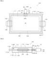
- FIG. 1 shows a plan view of a power storage device 100 including a valve structure 10 for a power storage device according to the present embodiment.
- FIG. 2 is a cross-sectional view taken along line D2-D2 in FIG. 1 .
- regions that are not originally visible from the outside are partially shown with dotted lines for reference purposes.
- the up-down direction and the left-right direction in FIG. 1 will respectively be referred to as “front-rear” and “left-right”, and the up-down direction in FIG. 2 will be referred to as "up-down”, unless specified otherwise.
- the orientation of the power storage device 100 when in use is, however, not limited thereto.
- the power storage device 100 includes a housing body 110, a power storage device element 120, a tab 130, and a tab film 140.
- the housing body 110 includes an internal space S1 and a peripheral sealing part 150.
- the power storage device element 120 is housed in the internal space S1 of the housing body 110.
- the tab 130 is joined at one end to the power storage device element 120, and protrudes outward at the other end from the peripheral sealing part 150 of the housing body 110, and is fused at a portion between the two ends to the peripheral sealing part 150 via the tab film 140.
- the housing body 110 includes a container 110A.
- the container 110A includes packaging materials 111 and 112.
- the packaging materials 111 and 112 are heat sealed and fused together, thereby forming the peripheral sealing part 150.
- This peripheral sealing part 150 forms the internal space S1 of the container 110A isolated from the external space.
- the peripheral sealing part 150 demarcates the periphery of the internal space S1 of the container 110A.
- the mode of heat sealing referred to here is envisaged to include modes such as ultrasonic fusing and heat fusing from a heat source.
- the peripheral sealing part 150 refers to a portion in which the packaging materials 111 and 112 are formed in an integrated manner through fusing. Note that, as shown in FIG.
- the packaging material 112 in the portion of the peripheral sealing part 150 where the tab 130 and the tab film 140 are sandwiched, the packaging material 112, the tab 130, a pair of tab films 140 and the packaging material 111 are formed in an integrated manner, and, in the portion of the peripheral sealing part 150 where only the pair of tab films 140 are sandwiched, the packaging material 112, the pair of tab films 140 and the packaging material 111 are formed in an integrated manner.
- the packaging materials 111 and 112 are constituted by a resin molded article or a film, for example.
- the resin molded article referred to here can be manufactured by methods such as injection molding, pressure molding, vacuum molding and blow molding, and in-mold molding may be performed in order to impart designability and functionality. Polyolefin, polyester, nylon, ABS and other types of resin can be used.
- the film referred to here is a resin film that can be manufactured by methods such as an inflation method and a T-die method, or is obtained by laminating such a resin film on a metal foil, for example.
- the film referred to here may or may not be a stretched film, and may be a single-layer film or a multilayer film.
- the multilayer film referred here may be manufactured by a coating method, may be obtained by a plurality of films being adhered together by an adhesive or the like, or may be manufactured by a multilayer extrusion method.
- the packaging materials 111 and 112 can be constituted in various ways, and, in the present embodiment, are constituted by a laminate film.
- the laminate film can be a laminate obtained by laminating a base material layer, a barrier layer and a heat-sealable resin layer.
- the base material layer functions as a base material of the packaging materials 111 and 112, and is typically a resin layer forming an outer layer side of the container 110A and having insulating properties.
- the barrier layer functions to prevent at least moisture or the like from infiltrating the power storage device 100, in addition to improving the strength of the packaging materials 111 and 112, and is typically a metal layer made of an aluminum alloy foil or the like.
- the heat-sealable resin layer is typically made of a heat sealable resin such as a polyolefin and forms the innermost layer of the container 110A.
- the container 110A is not particularly limited in terms of shape, and can be bag-shaped (pouch-shaped), for example.
- the pouch shape referred to here is conceivably a three-side seal pouch, a four-side seal pouch, a pillow pouch or a gusseted pouch.
- the container 110A of the present embodiment has a shape such as shown in FIGS. 1 and 2 , and is manufactured by the packaging material 111 molded in a tray shape and the packaging material 112 likewise molded in a tray shape and overlaid on the packaging material 111 being heat sealed along an outer peripheral portion thereof in plan view.
- the packaging material 111 includes a polygonal ring-shaped flange part 111A that corresponds to an outer peripheral portion in plan view, and a molded part 111B that is continuous with an inner edge of the flange part 111A and bulges downward therefrom.
- the packaging material 112 includes a polygonal ring-shaped flange part 112A that corresponds to an outer peripheral portion in plan view, and a molded part 112B that is continuous with the inner edge of the flange part 112A and bulges upward therefrom.
- the packaging materials 111 and 112 are overlaid one on the other such that the respective molded parts 111B and 112B bulge in opposite directions to each other.
- the flange part 111A of the packaging material 111 and the flange part 112A of the packaging material 112 are formed in an integrated manner through heat sealing, and constitute the peripheral sealing part 150.
- the peripheral sealing part 150 extends around the entire outer periphery of the container 110A and is formed in a polygonal ring shape. Note that one of the packaging materials 111 and 112 may be sheet-shaped.
- the power storage device element 120 includes at least a cathode, an anode and an electrolyte, and is, for example, a power storage member such as a lithium-ion battery (secondary battery) or a capacitor.
- a power storage member such as a lithium-ion battery (secondary battery) or a capacitor.
- gas can be produced in the internal space S1 of the container 110A.
- gases such as volatile organic solvent, carbon monoxide, carbon dioxide, methane, ethane, hydrogen and hydrogen fluoride can be produced in the internal space S1 of the container 110A, due to volatilization of organic solvent which is the electrolyte and decomposition of the electrolytic solution.
- the power storage device 100 is a capacitor
- gas can be produced in the internal space S1 of the container 110A due to a chemical reaction in the capacitor.
- the power storage device 100 may also be a solid-state battery, in which case the power storage device element 120 can include a solid electrolyte that can produce gas.
- the solid electrolyte is a sulfide-based solid electrolyte
- hydrogen sulfide gas can be produced.
- the tab 130 is a metal terminal that is used for input/output of power of the power storage device element 120.
- the tab 130 is disposed one at each of the end parts of the peripheral sealing part 150 of the container 110A in the right-left direction, with one tab 130 constituting a terminal on the cathode side and the other tab 130 constituting a terminal on the anode side.
- One end part of each tab 130 in the left-right direction is electrically connected to an electrode (cathode or anode) of the power storage device element 120 in the internal space S1 of the container 110A, and the other end part protrudes outward from the peripheral sealing part 150.
- the form of the power storage device 100 described above is particularly preferably used in an electrically driven vehicle such as an electric car or a hybrid car in which a large number of the power storage devices 100 are connected in series and used at a high voltage, for example.
- the two tabs 130 constituting the terminals of the cathode and anode are not particularly limited in terms of attachment position, and may, for example, be disposed on one side (the same side) of the peripheral sealing part 150.
- the tabs 130 are constituted by a metal material such as aluminum, nickel or copper, for example. If the power storage device element 120 is a lithium-ion battery, the tab 130 that is connected to the cathode is typically made of aluminum or the like, and the tab 130 that is connected to the anode is typically made of copper, nickel or the like.
- the tab 130 on the left side is sandwiched between the packaging materials 111 and 112 via the tab films 140 at the left end part of the peripheral sealing part 150.
- the tab 130 on the right side is also sandwiched between the packaging materials 111 and 112 via the tab films 140 at the right end part of the peripheral sealing part 150.
- the tab film 140 is a so-called adhesive film, and is configured to adhere to both the packaging materials 111 and 112 and the tabs 130 (metal).
- the tabs 130 and the innermost layers (heat-sealable resin layers) of the packaging materials 111 and 112 can be fixed together via the tab films 140, even if the materials thereof differ.
- the tab films 140 are formed in an integrated manner with the tabs 130 by being fused and fixed thereto in advance, and the peripheral sealing part 150 is integrally formed, as shown in FIG. 2 , by the tabs 130 to which the tab films 140 are fixed being sandwiched between the packaging materials 111 and 112 and fused.
- the housing body 110 includes a valve structure 10 as a mechanism for preventing such a situation.
- the valve structure 10 is a gas vent valve for adjusting the pressure inside the internal space S1, and is, for example, attached to the peripheral sealing part 150 of the container 110A.
- the configuration of the valve structure 10 will be described in detail.
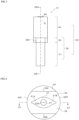
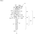
- FIG. 3 is a front view of the valve structure 10.
- the valve structure 10 includes a valve main body 20 and a liquid 70 (see FIGS. 7A and 8 ).
- the valve main body 20 includes a first body 30, a second body 40, a check valve 50 (see FIGS. 7A and 8 ), a sealing member 80, and a lid 90 (see FIGS. 7A and 8 ).
- the first body 30 and the second body 40 are disposed continuously in the stated order in a direction from the inside of the container 110A (see FIG. 1 ) to the outside (direction from the rear side to the front side).
- FIG. 4 is a diagram in which the valve structure 10 is viewed from the first body 30 side (from the rear side).
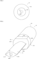
- FIG. 5 is a diagram in which the valve structure 10 is viewed from the second body 40 side (from the front side).
- FIG. 6 is a perspective view in which the valve structure 10 is viewed from the first body 30 side (from the rear side).
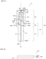
- FIG. 7A is a cross-sectional view taken along line D7-D7 in FIG. 4 .
- FIG. 8 is a cross-sectional view taken along line D8-D8 in FIG. 3 .
- the check valve 50 is housed in a housing space S2 demarcated by the first body 30 and the second body 40.
- the check valve 50 opens when the internal pressure of the container 110A (see FIG. 1 ) increases due to gas produced inside the container 110A, and passes the gas from the internal side of the container 110A to the external side.
- the check valve 50 constitutes a relief valve that switches between open and closed, according to the pressure on the primary side thereof, that is, the pressure inside the internal space S1 (see FIG. 1 ).
- a passage LA is formed in the housing space S2 inside the valve main body 20.
- the passage LA communicates the inside of the container 110A with the outside thereof, and includes an inlet 20A facing the internal space S1 of the container 110A and an outlet 20B facing the external space.
- the check valve 50 is disposed to block the passage LA in the closed state.
- the check valve 50 opens, and the gas is passed from the primary side to the secondary side of the check valve 50, that is, from the internal space S1 to the external space.
- the check valve 50 seals the internal space S1 from the external space in the closed state.
- the first body 30 includes an attachment part 31 and a coupling part 32.
- the attachment part 31 is for attaching the valve structure 10 to the container 110A.
- the attachment part 31 is heat sealed together with the packaging materials 111 and 112 via a heat fusion film 60 (see FIG. 1 ) during molding of the container 110A. Due to this heat sealing, the packaging materials 111 and 112 and the outer peripheral surface of the attachment part 31 are joined by fusing via the heat fusion film 60, and the attachment part 31 is fixed to the peripheral sealing part 150 in a state of being sandwiched between the packaging materials 111 and 112 (see FIG. 2 ).
- the coupling part 32 is disposed on the outer side of the peripheral sealing part 150 and is not sandwiched between the packaging materials 111 and 112 (see FIGS. 1 and 2 ).
- the second body 40 which is disposed further on the outer side than the coupling part 32 is also disposed on the outer side of the peripheral sealing part 150 and not sandwiched between the packaging materials 111 and 112.
- the attachment part 31, the coupling part 32 and the second body 40 extend coaxially to each other.
- the attachment part 31, the coupling part 32 and the second body 40 have a common central axis C1.
- the attachment part 31 has a first ventilation passage LX
- the second body 40 has a second ventilation passage LY
- the coupling part 32 has a third ventilation passage LZ.
- These ventilation passages LX to LZ also extend coaxially to each other centered on the central axis C1.
- the inlet 20A and the outlet 20B are disposed in the end faces of the valve main body 20 in the front-rear direction rather than in the outer peripheral surface thereof, and, in particular, the central axis C1 extending linearly in the front-rear direction passes through the center of the inlet 20A and outlet 20B.
- cross sections of the ventilation passages LX to LZ orthogonal to the central axis C1 are circular.
- the ventilation passages LX to LZ communicate with each other and together constitute the passage LA.
- the third ventilation passage LZ is disposed further on the external side of the container 110A than the first ventilation passage LX.
- the second ventilation passage LY is disposed further on the external side of the container 110A than the third ventilation passage LZ.
- the attachment part 31 has a non-circular outer shape when viewed along the direction in which the central axis C1 extends. More specifically, the attachment part 31 has a first wing-shaped part 31A and a second wing-shaped part 31B that are respectively formed to become thinner toward the left and right from a middle part thereof in the left-right direction, when viewed along the direction in which the central axis C1 extends. In the present embodiment, the attachment part 31 thus becomes thicker approaching the middle part thereof in the width direction of the power storage device 100 (left-right direction), and becomes thinner approaching the edge parts thereof in the width direction of the power storage device 100 (left-right direction).
- the lower half and upper half of the outer peripheral surface of the attachment part 31 that are respectively covered by the packaging material 111 and the packaging material 112 are both smoothly curved surfaces.
- the change in thickness in the up-down direction of the power storage device 100 where the peripheral sealing part 150 transitions from not sandwiching the attachment part 31 to sandwiching the attachment part 31 is smooth due to the first wing-shaped part 31A and the second wing-shaped part 31B.
- excessive force is not applied to the packaging materials 111 and 112 in portions of the peripheral sealing part 150 surrounding where the attachment part 31 is attached.
- the attachment part 31 can thus be firmly fixed to the peripheral sealing part 150 via the heat fusion film 60.
- the coupling part 32 has a generally columnar outer shape centered on the central axis C1 that is partially cut away. More specifically, the coupling part 32 has a generally columnar outer shape centered on the central axis C1 that is cut away in one plane spaced a certain distance away from the central axis C1 and is further cut away in another plane positioned symmetrically to the one plane with respect to the central axis C1. Therefore, the coupling part 32 has a first plane 32A and a second plane 32B that form a pair of planes. The first plane 32A and the second plane 32B are parallel (including substantially parallel; this similarly applying below) to each other.
- the first plane 32A and the second plane 32B are parallel (including substantially parallel; this similarly applying below) in the direction in which the central axis C1 extends. Also, in the present embodiment, the first plane 32A and the second plane 32B are parallel (including substantially parallel; this similarly applying below) in the direction in which the peripheral sealing part 150 extends.
- the outer peripheral surface of the coupling part 32 is constituted by the first plane 32A and the second plane 32B, and curved surfaces 32C and 32D that couple the first plane 32A and the second plane 32B to each other.
- the curved surfaces 32C and 32D both have a circular arc shape centered on the central axis C1 and overlap with the outer shape of the second body 40, when viewed along the direction in which the central axis C1 extends.
- a coupling part 32 such as described above can be formed by cutting the outer peripheral surface of a cylindrical member, such that the first plane 32A and the second plane 32B are formed. Constituting the outer shape of the coupling part 32 in this way makes the valve structure 10 easy to grasp. Carrying the valve structure 10 to the machining position and fixing the valve structure 10 at the machining position, for example, are thereby facilitated. The valve structure 10 can thus be easily attached to the container 110A.
- the second body 40 is cylindrical and demarcates the housing space S2 that, together with the first body 30, houses the check valve 50.
- the first body 30 and the second body 40 are assembled with the check valve 50 housed in the housing space S2.
- the first body 30 and the second body 40 are joined by at least one of an adhesive, a screw structure, and engagement of raised and recessed parts, for example.
- the first body 30 and the second body 40 are joined by the engagement of a male thread 32X (see FIG. 7A ) that is formed on the outer surface of the coupling part 32 of the first body 30 with a female thread 40A (see FIG. 7A ) that is formed on the inner surface of the second body 40 and an adhesive that is applied to the male thread 32X and the female thread 40A.
- the adhesive is not particularly limited in terms of material, and can be constituted by an acid-modified polyolefin and an epoxy resin. Such an adhesive is superior in terms of being able to suppress degradation of the adhesive performance caused by the electrolytic solution that is housed within the container 110A, as compared with the case where an adhesive made of modified silicone resin is used, for example. Note that any means can be employed in joining the first body 30 and the second body 40. In the present embodiment, at least one of the adhesive and the structure relating to engagement of the male thread 32X and the female thread 40A may thus be omitted.
- the attachment part 31, the coupling part 32 and the second body 40 all have different outer shapes, according to the roles allocated to the respective parts, when viewed along the direction in which the central axis C1 extends.
- the second body 40 holds a portion of the valve structure 10 that has a main structure for functioning as a gas venting valve.
- the check valve 50 has a spring 51, a valve body 52 and a valve seat 53 that serve as a valve mechanism that is housed within the second ventilation passage LY inside the second body 40.
- the spring 51, the valve body 52 and the valve seat 53 are disposed in the stated order toward the inlet 20A from the outlet 20B within the second ventilation passage LY.
- the first body 30 and the valve seat 53 are constituted as separate parts, as shown in FIGS. 7A and 8 , but may be constituted integrally.
- the valve seat 53 receives the valve body 52 that is biased from the outer side by the spring 51, at which time the valve structure 10 is closed.
- the spring 51 is, for example, a coil spring, but is not limited thereto, and can also be a leaf spring, for example.
- the valve seat 53 has a cylindrical shape that extends centered on the central axis C1, and has a top face 53A and a bottom face 53B that respectively define the end faces on the front and rear sides thereof in the front-rear direction.
- the valve body 52 is, for example, a ball-type valve body. Part of the surface of the valve body 52 is received by the top face 53A of the valve seat 53 and, when the check valve 50 is closed, comes in contact with the top face 53A.
- the spring 51 extends in a spiral shape centered on the central axis C1. The spring 51 is coupled to the valve body 52.
- the valve seat 53 and the first body 30 can be adhered by an adhesive, for example.
- the adhesive is not particularly limited in terms of material, and, as a preferred example in the case where the valve seat 53 is made of fluorocarbon rubber and the first body 30 is made of a metal such as aluminum, is similar to the adhesive illustrated for use when joining the first body 30 and the second body 40.
- an adhesive can also be applied as appropriate in various other places. For example, an adhesive can be applied between an end face 41 on the rear side of the second body 40 and an end face 32E on the front side of the coupling part 32.
- the attachment part 31 is fixed to the peripheral sealing part 150, such that gas produced in the internal space S1 of the container 110A flows into the first ventilation passage LX. That is, the first ventilation passage LX inside the attachment part 31 communicates with the internal space S1 of the container 110A. Therefore, when the pressure inside the internal space S1, that is, the pressure inside the space on the primary side of the check valve 50, reaches a predetermined pressure, gas that has flowed out of the internal space S1 and passed through the first ventilation passage LX and the third ventilation passage LZ pushes the valve body 52 to the outlet 20B side. When the valve body 52 is pushed and moves away from the valve seat 53, the check valve 50 opens due to the spring 51 deforming and the valve body 52 moving to the outlet 20B side.
- the check valve 50 is, in the closed state, able to prevent air from infiltrating the internal space S1 of the container 110A from the external space. After the check valve 50 has opened once, the internal space S1 is kept at a relatively high pressure at least comparable to the atmospheric pressure, and thus there is very little chance of air infiltrating the internal space S1.
- the valve structure 10 is, with a check valve 50 such as described above, able to effectively prevent air from infiltrating the internal space S1, and to prevent degradation of the power storage device element 120 caused by moisture or the like contained in the air. Also, even when the check valve 50 is open, there is little chance of air infiltrating the internal space S1. This is because, in the open state, the primary side of the check valve 50 is maintained at a pressure higher than or comparable to the pressure on the secondary side.
- the liquid 70 shown in FIGS. 7A and 8 is disposed in the housing space S2.
- the hatching in FIGS. 7A and 8 indicates an example of the range over which the liquid 70 is present.
- the liquid 70 is disposed in contact with the valve body 52 and the valve seat 53, in order to suppress infiltration of moisture into the internal space S1 (see FIG. 1 ).
- the type of liquid 70 is freely selectable.
- the liquid 70 is liquid paraffin.
- An ionic liquid, a liquid oil such as silicone oil or the like can also be used as the liquid 70.
- the liquid 70 preferably has the property of existing in liquid form in the normal use environment of the power storage device 100.
- the melting point of the liquid 70 is preferably 10 °C or less, and more preferably 0 °C or less.
- the boiling point of the liquid 70 is preferably 150 °C or greater.
- the temperatures illustrated as the melting point and boiling point of the liquid 70 are temperatures in the normal use environment of the power storage device 100.
- the power storage device 100 of the present embodiment is, for example, used at atmospheric pressure or in a vacuum.
- the power storage device 100 may also be used in an environment other than at atmospheric pressure or in a vacuum.
- the melting point of the liquid is measured based on "JIS K0064-1992 Test methods for melting point and melting range of chemical products".
- the boiling point of the liquid is measured by "JIS K0066-1992 Test methods for distillation of chemical products”.
- the measurement conditions for melting point and boiling point are normal temperature and normal humidity defined by "JIS Z8703-1983".
- the viscosity of the liquid 70 is freely selectable.
- the viscosity of the liquid is determined based on the viewpoint of suitably permeating the gas and the viewpoint of handling.
- a preferred example of the maximum viscosity of the liquid 70 is 2000 mPa ⁇ s. When the viscosity of the liquid 70 is 2000 mPa ⁇ s or less, the gas can be suitably permeated.
- a more preferred example of the maximum viscosity of the liquid 70 is 500 mPa ⁇ s.
- An even more preferred example of the maximum viscosity of the liquid 70 is 100 mPa ⁇ s.
- a preferred example of the minimum viscosity of the liquid 70 is 0.1 mPa ⁇ s.
- the liquid can be suitably handled.
- a more preferred example of the minimum viscosity of the liquid 70 is 0.5 mPa ⁇ s.
- An even more preferred example of the minimum viscosity of the liquid 70 is 1.0 mPa ⁇ s.
- An example of a preferred range of viscosity of the liquid 70 is 0.1 mPa ⁇ s to 2000 mPas.
- An example of a more preferred range of viscosity of the liquid 70 is 0.5 mPa ⁇ s to 500 mPas.
- An example of an even more preferred range of viscosity of the liquid 70 is 1.0 mPa ⁇ s to 100 mPas.
- the viscosity of the liquid 70 is the viscosity at 23 °C. Also, in the case where the liquid 70 is crude oil or petroleum, the viscosity of the liquid 70 is calculated by multiplying the kinematic viscosity measured based on "JIS K2283 Crude petroleum and petroleum products - Determination of kinematic viscosity and calculation of viscosity index from kinematic viscosity" by the density. In the case where the liquid 70 is other than crude oil or petroleum, the viscosity of the liquid 70 is measured based on the "JIS Z8803 methods for viscosity measurement of liquid".
- the specific mode of disposition of the liquid 70 is freely selectable, as long as the liquid 70 comes in contact with the valve body 52 and the valve seat 53.
- a predetermined range of the housing space S2 is filled with the liquid 70.
- the housing space S2 is filled with the liquid 70 through at least one of the inlet 20A and the outlet 20B after assembling the first body 30 and the second body 40, for example.
- gas produced in the internal space S1 flows out through the gap formed between the valve body 52 and the valve seat 53.
- the outflowing gas passes through the liquid 70 in the form of bubbles, and flows out toward the outlet 20B after passing through the liquid 70.
- the liquid 70 prevents moisture or the like from infiltrating further to the internal side of the container 110A than the check valve 50. Infiltration of air and moisture or the like contained in the air into the container 110A is thus suppressed.
- the liquid 70 need only at least adhere to the portion of the surface of the valve body 52 that comes in contact with the valve seat 53 and the portion of the surface of the valve seat 53 that comes in contact with the valve body 52, when the check valve 50 is closed.
- Such a mode of disposition of the liquid 70 can be formed by injecting air through the inlet 20A to dispel the liquid 70, in the state shown in FIG.
- the liquid 70 forms a film on the portion of the surface of the valve body 52 that comes in contact with the valve seat 53 and on the portion of the surface of the valve seat 53 that comes in contact with the valve body 52, when the check valve 50 is closed.
- gas produced in the internal space S1 passes through the film of liquid 70 in the form of bubbles or breaks through the film of liquid 70 and flows out toward the outlet 20B. If the gas breaks through the film of liquid 70, the valve body 52 and the valve seat 53 come in contact, due to the check valve 50 transitioning from open to closed, and the film of liquid 70 forms again.
- valve body 52 can be made of a fluorocarbon resin such as PolyTetraFluoroEthylene (PTFE), and the valve seat 53 can be made of fluorocarbon rubber such as fluoroelastomer (FKM) rubber.
- FKM fluoroelastomer
- the spring 51 can be made of a metal such as stainless steel
- the attachment part 31, the second body 40 and the coupling part 32 can be made of a metal such as an aluminum alloy, stainless steel, sheet steel or titanium.
- the second body 40 is responsible for protecting the check valve 50, and thus is preferably made of a metal.
- the valve body 52 can also be made of a metal such as stainless steel or a fluorocarbon rubber such as FKM rubber. Note that in the case where the valve body 52 is made of a fluorocarbon rubber such as FKM rubber, the valve seat 53 is preferably made of a fluorocarbon resin such as PTFE.
- the attachment part 31 and the second body 40 may be constituted by the same material or may be constituted by different materials.
- the attachment part 31 is constituted by a resin
- the outer peripheral surface of the attachment part 31 is joined by fusing to the packaging materials 111 and 112, and thus the heat fusion film 60 described later is not required.
- the configuration of the power storage device 100 can thus be simplified.
- the resin constituting the attachment part 31 is, for example, a fluorocarbon resin, a polyester resin, a polyimide resin, a polycarbonate resin, a polyolefin resin or an acrylic resin.
- the second body 40 is preferably constituted by a material having a higher melting point than the material constituting the attachment part 31. According to such a configuration, since the second body 40 is constituted by a material having a higher melting point than the material constituting the attachment part 31, the chances of the check valve 50 being deformed or damaged can be reduced, even when pressure and heat are applied to the attachment part 31 at the time of fusing the opposing heat-fusible resin layers of the packaging materials 111 and 112.
- a configuration may be adopted in which the first body 30 and the second body 40 are entirely constituted by a metal or a resin.
- a configuration may also be adopted in which the first body 30 and the second body 40 are entirely constituted by a material made of a mixture of a metal and a resin.
- a configuration may also be adopted in which the first body 30 is constituted by a material made of a mixture of a metal and a resin, and the second body 40 is constituted by a metal.
- a configuration may also be adopted in which the first body 30 is constituted by a resin and the second body 40 is constituted by a metal.
- the outer peripheral surface of the attachment part 31 is joined by fusing to the packaging materials 111 and 112, and thus the heat fusion film 60 described later is not required.
- the first wing-shaped part 31A and the second wing-shaped part 31B of the attachment part 31 can be easily machined.
- the attachment part 31 can be precisely heat sealed to the packaging materials 111 and 112.
- the resin constituting the first body 30 and the second body 40 include an olefin resin, in addition to the resin constituting the attachment part 31 described above.
- An olefin resin is, for example, acid-modified polypropylene or a resin obtained by two-shot molding acid-modified polypropylene and polypropylene. Note that, in the case where a resin material is extrusion molded on a metal material, a coating of a corrosion inhibitor described later is preferably applied to the surface of the portion that is constituted by the metal material to form a corrosion inhibitor coating layer.
- the heat fusion film 60 shown in FIG. 1 and the like is configured to adhere to both the valve structure 10 and the packaging materials 111 and 112 of the container 110A by heat sealing.
- the heat fusion film 60 is fused to the attachment part 31 of the first body 30, prior to the first body 30 and the second body 40 are assembled, while the check valve 50 is housed in the housing space S2 (see FIG. 7A ).
- the heat fusion film 60 is fused to the attachment part 31 so as to cover most of the surface of the attachment part 31.
- Various known adhesive films can be employed as the heat fusion film 60.
- the heat fusion film 60 may, for example, be a single-layer film of maleic anhydride-modified polypropylene (PPa), or a laminate film having multiple layers consisting of a PPa layer, a polyethylene naphthalate (PEN) layer and a PPa layer.
- the heat fusion film 60 may also be a laminate film having multiple layers consisting of a PPa layer, a polypropylene (PP) layer and a PPa layer.
- a metal adhesive resin such as an ionomer resin, modified polyethylene or EVA is also applicable.
- the heat fusion film 60 employs a laminate film having a three-layer structure containing a core material and consisting of a PPa layer, a polyester fiber layer and a PPa layer.
- a core material may be a polyester film made of PEN, polyethylene terephthalate, polybutylene terephthalate or the like, or may be polyamide fiber or carbon fiber.
- the surface of the attachment part 31 is coated with a corrosion inhibitor to form a corrosion inhibitor coating layer.
- a corrosion inhibitor to form a corrosion inhibitor coating layer.
- Such coating can be performed by immersing the attachment part 31 in a corrosion inhibitor liquid and then implementing a baking process.
- a corrosion inhibitor coating layer can thereby be formed on the outer surface of the attachment part 31 and the inner surface facing the first ventilation passage LX, and corrosion of the outer surface due to gas produced by the power storage device element 120 and corrosion of the inner surface due to gas passing through the first ventilation passage LX can be prevented.
- a similar coating may also be applied to the surfaces of the coupling part 32, the second body 40 and the check valve 50, in addition to the attachment part 31, to form a corrosion prevention coating layer.
- the corrosion prevention coating layer is preferably formed over a predetermined range that particularly includes places where the valve seat 53 comes in contact the second body 40, the valve body 52, the male thread 32X of the coupling part 32 and the female thread 40A of the second body 40.
- the corrosion inhibitor is preferably acid-resistant, and the corrosion inhibitor coating layer can be formed by a chromic acid chromate treatment, a phosphoric acid chromate treatment or the like.
- the sealing member 80 is attached to the second body 40 so as to close the outlet 20B. For example, leakage of the liquid 70 from the outlet 20B during transportation of the valve structure 10 and contamination of the inside of the valve structure 10 by foreign matter through the outlet 20B are thus suppressed.
- the sealing member 80 is peeled off the second body 40.
- the sealing member 80 shown in FIG. 7B includes, for example, a surface layer 81 that closes the outlet 20B and a base material layer 82 that is laminated on the surface layer 81.
- the sealing member 80 may be an adhesive containing an acrylic resin, or may be a single-layer structure having only the surface layer 81.
- the material constituting the surface layer 81 preferably includes at least one of a polyolefin and an elastomer, for example.
- a polyolefin is present on the surface of the surface layer 81, the sealing member 80 can be easily peeled off the second body 40 at the time of using the valve structure 10.
- the polyolefin is polyethylene or polypropylene, for example.
- the surface layer 81 has adhesiveness, thus enabling the sealing member 80 to be easily positioned relative to the outlet 20B.
- the elastomer is, for example, a thermoplastic elastomer.
- the base material layer 82 includes, for example, a first base material layer 82A laminated on the surface layer 81 and a second base material layer 82B laminated on the first base material layer 82A.
- the material constituting the first base material layer 82A preferably includes a metal such as an aluminum alloy, from the viewpoint of improving water vapor barrier properties and airtightness, for example.
- the sealing member 80 has stiffness as a whole, and thus can be easily peeled off the second body 40.
- the second base material layer 82B is laminated on the first base material layer 82A via an adhesive, for example.
- the material constituting the second base material layer 82B includes polyethylene terephthalate, for example.
- the lid 90 has a pore diameter of 10 -2 um to 10° um, for example, and is, for example, constituted by a PTFE (PolyTetraFluoroEthylene) membrane that selectively permeates only gas, and does not permeate the organic solvent contained in the power storage device element 120 or the liquid 70.
- the PTFE membrane is soft, and thus, in the case of having insufficient strength, a mesh made of polypropylene, polyester or the like or a nonwoven fabric may be integrally molded with the PTFE membrane and this reinforced PTFE membrane may be used as the lid 90.
- the material constituting the lid 90 may, for example, be a metal mesh, a synthetic resin mesh, or a nonwoven fabric.
- the lid 90 includes a first lid 91 that is disposed on the primary side of the check valve 50 and a second lid 92 that is disposed on the secondary side of the check valve 50.
- the first lid 91 inhibits the organic solvent contained in the power storage device element 120 (see FIG. 2 ) from passing through the passage LA, opening the check valve 50, and flowing outside the valve main body 20.
- the position where the first lid 91 is disposed in the valve main body 20 is freely selectable, as long as the position is on the primary side of the check valve 50.
- the first lid 91 is disposed in the vicinity of the bottom face 53B of the valve seat 53 in the passage LA.
- the first lid 91 may also be disposed in the vicinity of the inlet 20A in the passage LA, or may also be disposed anywhere between the bottom face 53B of the valve seat 53 and the inlet 20A.
- the second lid 92 inhibits the liquid 70 from leaking out through the outlet 20B, when the sealing member 80 has been peeled off, such as during use of the valve structure 10, for example.
- the second lid 92 is, for example, disposed in the vicinity of the outlet 20B.
- the second lid 92 may be disposed anywhere between the surface of the liquid 70 and the outlet 20B.
- the configuration of the valve structure 10 differs, as compared with the first embodiment.
- the remaining configuration is basically similar to the first embodiment.
- configuration that is the same as the first embodiment will be given the same reference numerals and description thereof will be omitted, with the following description focusing on the differences from the first embodiment.
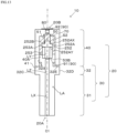
- FIG. 9 is a front view of a valve structure 200 of the second embodiment.
- FIG. 10 is a cross-sectional view taken along line D10-D10 in FIG. 9 .
- the second body 40 of the present embodiment is configured to hold a plurality of check valves 50.
- the second body 40 holds two check valves 50.
- the check valve 50 that is disposed closer to the inlet 20A may be referred to as check valve 210
- the check valve 50 that is disposed closer to the outlet 20B may be referred to as check valve 220.
- the check valves 210 and 220 are arranged along the direction in which the passage LA extends, with the check valve 220 disposed on the secondary side (external side) of the check valve 210. Gas produced in the internal space S1 (see FIG. 1 ) can be discharged through the passage LA to outside the container 110A by opening the check valves 210 and 220. Note that the check valves 210 and 220 do not necessarily open at the same time, and often open at different times.
- the check valves 210 and 220 are disposed at different positions along the direction in which the passage LA extends to block the passage LA in the closed state.
- the portion (valve box) of the check valves 210 and 220 that constitutes the body is constituted by the second body 40, and the valve mechanism included in the check valves 210 and 220 is disposed inside the second body 40.
- a space included in the passage LA and positioned on the secondary side (external side) of the check valve 210 and the primary side (internal side) of the check valve 220 will be referred to below as inter-valve space S3.
- the check valve 210 opens when the pressure inside the internal space S1 increases due to gas produced in the internal space S1, and passes gas from the primary side thereof to the secondary side thereof, that is, to the inter-valve space S3.
- the check valve 220 opens when the pressure inside the inter-valve space S3 thus increases, and passes gas from the primary side thereof to the secondary side thereof, that is, to the external space.
- the valve structure 200 seals the internal space S1 from the external space when either of the check valves 210 and 220 is closed.
- the check valve 210 opens and the pressure inside the inter-valve space S3 that is included in the second vent passage LY, that is, the pressure inside the space on the primary side of the check valve 220, reaches a predetermined pressure, the gas in the inter-valve space S3 pushes the valve body 52 to the outlet 20B side.
- the check valve 220 opens due to the spring 51 deforming and the valve body 52 moving to the outlet 20B side. In this open state, the gas contained in the valve inter-valve space S3 flows out toward the outlet 20B through the gap formed between the valve body 52 and the valve seat 53, and is discharged to the external space through the outlet 20B.
- the check valves 210 and 220 are, in the closed state, both able to prevent air from infiltrating the internal space S1 of the container 110A from the external space. Note that, in order for air to infiltrate the internal space S1 from the external space, the air has to flow back through the plurality of check valves 210 and 220, and thus there is little chance of air infiltrating the internal space S1 in such a manner. Also, after the check valve 210 has opened once, the inter-valve space S3 is kept at a relatively high pressure at least comparable to the atmospheric pressure, and thus there is little chance of air infiltrating the inter-valve space S3 from the external space.
- valve structure 200 is able to effectively prevent air from infiltrating the internal space S1 with the check valves 210 and 220 that are disposed in multiple stages along the passage LA, and to prevent degradation of the power storage device element 120 caused by moisture or the like contained in the air.
- the valve opening pressure of the check valves 210 and 220 can be set as appropriate, and the valve opening pressure of the check valve 210 may be any of (i) equal to the valve opening pressure of the check valve 220, (ii) lower than the opening pressure of the check valve 220, or (iii) higher than the opening pressure of the check valve 220, although for the following reasons (i) and (ii) are preferable.
- the pressure inside the internal space S1 can be maintained higher, and thus the pressure difference between the internal space S1 and the external space prevents the air of the external space from infiltrating the internal space S1 more effectively.
- the valve opening pressures of the check valves 210 and 220 can both be set to 0.05 MPa.
- the valve opening pressure of the valve structure 200 as a whole is the sum of the valve opening pressures of the check valves 210 and 220, and is thus 0.1 MPa in this example.
- the valve opening pressure is the pressure difference between the pressure on the primary side and the pressure on the secondary side.
- the inter-valve space S3 is preferably filled with gas to a higher pressure than atmospheric pressure, prior to or immediately after attaching the valve structure 200 to the container 110A.
- the inter-valve space S3 is kept at a higher pressure than atmospheric pressure, from immediately after the power storage device 100 is manufactured, that is, from before the check valve 210 is first opened.
- infiltration of air from the external space into the inter-valve space S3 and, consequently, into the internal space S1 is more effectively prevented.
- this inspection can also serve as a step for filling the inter-valve space S3 with gas.
- the gas with which the inter-valve space S3 is filled is preferably an inert gas such as argon.
- the valve opening inspection need only be performed using an inert gas. In this case, degradation of the power storage device element 120 due to gas slightly infiltrating the internal space S1 is also prevented.
- the liquid 70 is disposed to come in contact with the valve body 52 and valve seat 53 of the check valve 210, in order to suppress infiltration of moisture into the internal space S1 (see FIG. 1 ).
- the specific mode of disposition of the liquid 70 is freely selectable, as long as the liquid 70 comes in contact with the valve body 52 and the valve seat 53.
- a predetermined range of the inter-valve space S3 is filled with the liquid 70.
- the inter-valve space S3 may be filled with the liquid 70 prior to assembling the check valve 210 and the check valve 220, or may be filled through the inlet 20A after assembling the check valve 210 and the check valve 220, for example.
- the inter-valve space S3 may be filled with the liquid 70 through the outlet 20B, prior to disposing the spring 51 and the valve body 52 of the check valve 220.
- the liquid 70 need only at least adhere to the portion of the surface of the valve body 52 that comes in contact with the valve seat 53 and the portion of the surface of the valve seat 53 that comes in contact with the valve body 52, when the check valve 210 is closed.
- Such a mode of disposition of the liquid 70 can be formed by injecting air through the inlet 20A to dispel the liquid 70 in the state shown in FIG. 10 , for example.
- gas produced in the internal space S1 flows out through the gap formed between the valve body 52 and the valve seat 53.
- the outflowing gas passes through the liquid 70 in the form of bubbles, and then flows out toward the outlet 20B after passing through the liquid 70.
- the liquid 70 prevents moisture or the like from infiltrating further to the internal side of the container 110A than the check valve 210. Infiltration of air and moisture or the like contained in the air into the container 110A is thus suppressed.
- valve structure for a power storage device and the power storage device relating to the present invention are not intended to restrict the forms thereof.
- the valve structure for a power storage device and the power storage device relating to the present invention can take different forms from the forms illustrated in the embodiments.
- One example is a form in which some of the configuration of the embodiments is replaced, modified or omitted, or a form in which configuration is newly added to the embodiments.
- a number of examples of variations of the embodiments will be shown below. Note that the gist of the following variations is similarly applicable to the second embodiment in addition to the first embodiment.
Landscapes
- Chemical & Material Sciences (AREA)
- Chemical Kinetics & Catalysis (AREA)
- Electrochemistry (AREA)
- General Chemical & Material Sciences (AREA)
- Engineering & Computer Science (AREA)
- General Engineering & Computer Science (AREA)
- Mechanical Engineering (AREA)
- Gas Exhaust Devices For Batteries (AREA)
- Electric Double-Layer Capacitors Or The Like (AREA)
- Sealing Battery Cases Or Jackets (AREA)
- Packages (AREA)
Abstract
Description
- The present invention relates to a valve structure for a power storage device and a power storage device including the same.
-
Patent Document 1 discloses a battery housing a battery element in a pouch. In the pouch, a valve structure having a check valve is attached to a heat sealing part that is formed around the periphery of the pouch. This check valve is configured to operate when the internal pressure of the pouch increases to a certain level and vent gas. - Also,
Patent Document 2 discloses a battery housing a battery element in a box-shaped laminated container. In this laminated container, a flange-shaped heat sealing part that is formed around the periphery of the laminated container peels off more easily in one place (hereinafter, easy peel part) than in other regions. The easy peel part peels off when the internal pressure of the laminated container increases to a certain level, and gas is vented through a hole that is formed in the middle of the easy peel part. The easy peel part is a breaker valve that does not return to its original state once it has peeled off, unlike a check valve such as described inPatent Document 1. -
- Patent Literature 1:
JP 2016-31934 - Patent Literature 2:
JP 2010-153841 - Incidentally, a check valve is generally a one-way valve and serves to prevent backflow. However, with a battery such as described in
Patent Document 1, the battery degrades when the pouch is contaminated with even a small amount of moisture contained in the air, and thus backflow needs be prevented with a high degree of precision. Thus, it is difficult, in practice, for a check valve that vents gas produced inside a pouch such as described inPatent Document 1 to completely prevent air from infiltrating the pouch at a high level such as required for a battery. Therefore, with a battery such as described inPatent Document 1, there is a problem in that the pouch becomes contaminated with moisture contained in the air, causing the battery to degrade. - On the other hand, with a battery such as described in
Patent Document 2, once the breaker valve ruptures, air infiltrates the laminated container via a passage formed by the rupture. Therefore, even in the case where a breaker valve is used such as described inPatent Document 2, there is a problem that the laminated container is contaminated with moisture contained in the air, causing the battery to degrade. - An object of the present invention is to provide a valve structure that is able to suppress infiltration of moisture into a container housing a power storage device element, and a power storage device including the same.
- A valve structure for a power storage device according to a first aspect of the present invention includes a passage configured to communicate an interior of a container housing a power storage device element with an exterior of the container, and a check valve disposed to block the passage and configured to open when an internal pressure of the container increases due to gas produced inside the container and pass the gas from an internal side of the container to an external side, the check valve including a valve seat and a valve body, and the valve structure including a liquid disposed to come in contact with the valve seat and the valve body.
- A valve structure for a power storage device according to a second aspect of the present invention is the valve structure for a power storage device according to the first aspect, in which the liquid has a melting point not higher than 10 °C.
- A valve structure for a power storage device according to a third aspect of the present invention is the valve structure for a power storage device according to the first or second aspect, in which the liquid has a boiling point not less than 150 °C.
- A valve structure for a power storage device according to a fourth aspect of the present invention is the valve structure for a power storage device according to any one of the first to third aspects, in which the liquid includes liquid paraffin.
- A valve structure for a power storage device according to a fifth aspect of the present invention is the valve structure for a power storage device according to any one of the first to fourth aspects, in which the liquid has a viscosity in a range of 0.1 mPa·s to 2000 mPa·s.
- A valve structure for a power storage device according to a sixth aspect of the present invention is the valve structure for a power storage device according to any one of the first to fifth aspects, in which the passage includes an outlet facing an external space, and the valve structure includes a sealing member attached to close the outlet.
- A valve structure for a power storage device according to a seventh aspect of the present invention is the valve structure for a power storage device according to any one of the first to sixth aspects, in which the valve structure includes a lid disposed at least on one of a primary side and a secondary side of the check valve and configured to permeate the gas.
- A power storage device according to an eighth aspect of the present invention includes the valve structure for a power storage device according to any one of the first to seventh aspects, and the container to which the valve structure for a power storage device is attached.
- According to a valve structure for a power storage device and a power storage device relating to the present invention, infiltration of moisture into a container housing a power storage device element can be suppressed.
-
-
FIG. 1 is a plan view of a power storage device including a valve structure for a power storage device according to a first embodiment. -
FIG. 2 is a cross-sectional view taken along line D2-D2 inFIG. 1 . -
FIG. 3 is a front view of the valve structure inFIG. 1 . -
FIG. 4 is a bottom view of the valve structure inFIG. 3 . -
FIG. 5 is a plan view of the valve structure inFIG. 3 . -
FIG. 6 is a perspective view from a rear side of the valve structure inFIG. 3 . -
FIG. 7A is a cross-sectional view taken along line D7-D7 inFIG. 4 . -
FIG. 7B is a cross-sectional view of a sealing member inFIG. 7A . -
FIG. 8 is a cross-sectional view taken along line D8-D8 inFIG. 3 . -
FIG. 9 is a front view of the valve structure for a power storage device according to a second embodiment. -
FIG. 10 is a cross-sectional view taken along line D10-D10 inFIG. 9 . -
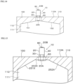
FIG. 11 is a cross-sectional view of a valve structure of a variation. -
FIG. 12 is a cross-sectional view of a valve structure of another variation. -
FIG. 13 is a cross-sectional view of a valve structure of yet another variation. -
FIG. 14 is a plan view of a power storage device of a variation. -
FIG. 15 is a plan view of a power storage device of another variation. -
FIG. 16 is a plan view of a power storage device of yet another variation. -
FIG. 17 is a plan view of a power storage device of yet another variation. - Hereinafter, a valve structure for a power storage device according to one embodiment of the present invention, a power storage device including the same, and a method of manufacturing the same will be described, with reference to the drawings.
-
FIG. 1 shows a plan view of apower storage device 100 including avalve structure 10 for a power storage device according to the present embodiment.FIG. 2 is a cross-sectional view taken along line D2-D2 inFIG. 1 . In these diagrams, regions that are not originally visible from the outside are partially shown with dotted lines for reference purposes. Hereinafter, for convenience of description, the up-down direction and the left-right direction inFIG. 1 will respectively be referred to as "front-rear" and "left-right", and the up-down direction inFIG. 2 will be referred to as "up-down", unless specified otherwise. The orientation of thepower storage device 100 when in use is, however, not limited thereto. - The
power storage device 100 includes ahousing body 110, a powerstorage device element 120, atab 130, and atab film 140. Thehousing body 110 includes an internal space S1 and aperipheral sealing part 150. The powerstorage device element 120 is housed in the internal space S1 of thehousing body 110. Thetab 130 is joined at one end to the powerstorage device element 120, and protrudes outward at the other end from the peripheral sealingpart 150 of thehousing body 110, and is fused at a portion between the two ends to the peripheral sealingpart 150 via thetab film 140. - The
housing body 110 includes acontainer 110A. Thecontainer 110A includespackaging materials container 110A in plan view, thepackaging materials part 150. This peripheral sealingpart 150 forms the internal space S1 of thecontainer 110A isolated from the external space. Theperipheral sealing part 150 demarcates the periphery of the internal space S1 of thecontainer 110A. Note that the mode of heat sealing referred to here is envisaged to include modes such as ultrasonic fusing and heat fusing from a heat source. In any case, the peripheral sealingpart 150 refers to a portion in which thepackaging materials FIG. 2 , in the portion of the peripheral sealingpart 150 where thetab 130 and thetab film 140 are sandwiched, thepackaging material 112, thetab 130, a pair oftab films 140 and thepackaging material 111 are formed in an integrated manner, and, in the portion of the peripheral sealingpart 150 where only the pair oftab films 140 are sandwiched, thepackaging material 112, the pair oftab films 140 and thepackaging material 111 are formed in an integrated manner. - The
packaging materials - As described above, the
packaging materials packaging materials container 110A and having insulating properties. The barrier layer functions to prevent at least moisture or the like from infiltrating thepower storage device 100, in addition to improving the strength of thepackaging materials container 110A. - The
container 110A is not particularly limited in terms of shape, and can be bag-shaped (pouch-shaped), for example. The pouch shape referred to here is conceivably a three-side seal pouch, a four-side seal pouch, a pillow pouch or a gusseted pouch. Thecontainer 110A of the present embodiment, however, has a shape such as shown inFIGS. 1 and 2 , and is manufactured by thepackaging material 111 molded in a tray shape and thepackaging material 112 likewise molded in a tray shape and overlaid on thepackaging material 111 being heat sealed along an outer peripheral portion thereof in plan view. Thepackaging material 111 includes a polygonal ring-shapedflange part 111A that corresponds to an outer peripheral portion in plan view, and a moldedpart 111B that is continuous with an inner edge of theflange part 111A and bulges downward therefrom. Similarly, thepackaging material 112 includes a polygonal ring-shapedflange part 112A that corresponds to an outer peripheral portion in plan view, and a moldedpart 112B that is continuous with the inner edge of theflange part 112A and bulges upward therefrom. Thepackaging materials parts flange part 111A of thepackaging material 111 and theflange part 112A of thepackaging material 112 are formed in an integrated manner through heat sealing, and constitute the peripheral sealingpart 150. Theperipheral sealing part 150 extends around the entire outer periphery of thecontainer 110A and is formed in a polygonal ring shape. Note that one of thepackaging materials - The power
storage device element 120 includes at least a cathode, an anode and an electrolyte, and is, for example, a power storage member such as a lithium-ion battery (secondary battery) or a capacitor. When an anomaly occurs in the powerstorage device element 120, gas can be produced in the internal space S1 of thecontainer 110A. In the case where thepower storage device 100 is a lithium-ion battery, gases such as volatile organic solvent, carbon monoxide, carbon dioxide, methane, ethane, hydrogen and hydrogen fluoride can be produced in the internal space S1 of thecontainer 110A, due to volatilization of organic solvent which is the electrolyte and decomposition of the electrolytic solution. In the case where thepower storage device 100 is a capacitor, gas can be produced in the internal space S1 of thecontainer 110A due to a chemical reaction in the capacitor. Thepower storage device 100 may also be a solid-state battery, in which case the powerstorage device element 120 can include a solid electrolyte that can produce gas. For example, if the solid electrolyte is a sulfide-based solid electrolyte, hydrogen sulfide gas can be produced. - The
tab 130 is a metal terminal that is used for input/output of power of the powerstorage device element 120. Thetab 130 is disposed one at each of the end parts of the peripheral sealingpart 150 of thecontainer 110A in the right-left direction, with onetab 130 constituting a terminal on the cathode side and theother tab 130 constituting a terminal on the anode side. One end part of eachtab 130 in the left-right direction is electrically connected to an electrode (cathode or anode) of the powerstorage device element 120 in the internal space S1 of thecontainer 110A, and the other end part protrudes outward from the peripheral sealingpart 150. The form of thepower storage device 100 described above is particularly preferably used in an electrically driven vehicle such as an electric car or a hybrid car in which a large number of thepower storage devices 100 are connected in series and used at a high voltage, for example. Note that the twotabs 130 constituting the terminals of the cathode and anode are not particularly limited in terms of attachment position, and may, for example, be disposed on one side (the same side) of the peripheral sealingpart 150. - The
tabs 130 are constituted by a metal material such as aluminum, nickel or copper, for example. If the powerstorage device element 120 is a lithium-ion battery, thetab 130 that is connected to the cathode is typically made of aluminum or the like, and thetab 130 that is connected to the anode is typically made of copper, nickel or the like. - The
tab 130 on the left side is sandwiched between thepackaging materials tab films 140 at the left end part of the peripheral sealingpart 150. Thetab 130 on the right side is also sandwiched between thepackaging materials tab films 140 at the right end part of the peripheral sealingpart 150. - The
tab film 140 is a so-called adhesive film, and is configured to adhere to both thepackaging materials tabs 130 and the innermost layers (heat-sealable resin layers) of thepackaging materials tab films 140, even if the materials thereof differ. Note that thetab films 140 are formed in an integrated manner with thetabs 130 by being fused and fixed thereto in advance, and the peripheral sealingpart 150 is integrally formed, as shown inFIG. 2 , by thetabs 130 to which thetab films 140 are fixed being sandwiched between thepackaging materials - When gas is produced in the internal space S1 of the
container 110A following operation of thepower storage device 100, the pressure inside the internal space S1 gradually increases. When the pressure inside the internal space S1 increases excessively, thecontainer 110A could possibly burst and thepower storage device 100 could be damaged. Thehousing body 110 includes avalve structure 10 as a mechanism for preventing such a situation. Thevalve structure 10 is a gas vent valve for adjusting the pressure inside the internal space S1, and is, for example, attached to the peripheral sealingpart 150 of thecontainer 110A. Hereinafter, the configuration of thevalve structure 10 will be described in detail. -
FIG. 3 is a front view of thevalve structure 10. Thevalve structure 10 includes a valvemain body 20 and a liquid 70 (seeFIGS. 7A and8 ). The valvemain body 20 includes afirst body 30, asecond body 40, a check valve 50 (seeFIGS. 7A and8 ), a sealingmember 80, and a lid 90 (seeFIGS. 7A and8 ). In the present embodiment, thefirst body 30 and thesecond body 40 are disposed continuously in the stated order in a direction from the inside of thecontainer 110A (seeFIG. 1 ) to the outside (direction from the rear side to the front side).FIG. 4 is a diagram in which thevalve structure 10 is viewed from thefirst body 30 side (from the rear side).FIG. 5 is a diagram in which thevalve structure 10 is viewed from thesecond body 40 side (from the front side).FIG. 6 is a perspective view in which thevalve structure 10 is viewed from thefirst body 30 side (from the rear side). -
FIG. 7A is a cross-sectional view taken along line D7-D7 inFIG. 4 .FIG. 8 is a cross-sectional view taken along line D8-D8 inFIG. 3 . As shown inFIGS. 7A and8 , thecheck valve 50 is housed in a housing space S2 demarcated by thefirst body 30 and thesecond body 40. Thecheck valve 50 opens when the internal pressure of thecontainer 110A (seeFIG. 1 ) increases due to gas produced inside thecontainer 110A, and passes the gas from the internal side of thecontainer 110A to the external side. More specifically, thecheck valve 50 constitutes a relief valve that switches between open and closed, according to the pressure on the primary side thereof, that is, the pressure inside the internal space S1 (seeFIG. 1 ). A passage LA is formed in the housing space S2 inside the valvemain body 20. The passage LA communicates the inside of thecontainer 110A with the outside thereof, and includes aninlet 20A facing the internal space S1 of thecontainer 110A and anoutlet 20B facing the external space. - The
check valve 50 is disposed to block the passage LA in the closed state. When the pressure inside the internal space S1 increases due to gas produced in the internal space S1, thecheck valve 50 opens, and the gas is passed from the primary side to the secondary side of thecheck valve 50, that is, from the internal space S1 to the external space. Thecheck valve 50 seals the internal space S1 from the external space in the closed state. - The
first body 30 includes anattachment part 31 and acoupling part 32. Theattachment part 31 is for attaching thevalve structure 10 to thecontainer 110A. Theattachment part 31 is heat sealed together with thepackaging materials FIG. 1 ) during molding of thecontainer 110A. Due to this heat sealing, thepackaging materials attachment part 31 are joined by fusing via theheat fusion film 60, and theattachment part 31 is fixed to the peripheral sealingpart 150 in a state of being sandwiched between thepackaging materials 111 and 112 (seeFIG. 2 ). - The
coupling part 32 is disposed on the outer side of the peripheral sealingpart 150 and is not sandwiched between thepackaging materials 111 and 112 (seeFIGS. 1 and 2 ). Thesecond body 40 which is disposed further on the outer side than thecoupling part 32 is also disposed on the outer side of the peripheral sealingpart 150 and not sandwiched between thepackaging materials check valve 50 that is held by thesecond body 40 being damaged by deformation or the like due to the heat at the time of attaching theattachment part 31 to thecontainer 110A by heat sealing is reduced. - The
attachment part 31, thecoupling part 32 and thesecond body 40 extend coaxially to each other. Theattachment part 31, thecoupling part 32 and thesecond body 40 have a common central axis C1. Theattachment part 31 has a first ventilation passage LX, thesecond body 40 has a second ventilation passage LY, and thecoupling part 32 has a third ventilation passage LZ. These ventilation passages LX to LZ also extend coaxially to each other centered on the central axis C1. In the present embodiment, theinlet 20A and theoutlet 20B are disposed in the end faces of the valvemain body 20 in the front-rear direction rather than in the outer peripheral surface thereof, and, in particular, the central axis C1 extending linearly in the front-rear direction passes through the center of theinlet 20A andoutlet 20B. Although not limited thereto, cross sections of the ventilation passages LX to LZ orthogonal to the central axis C1 are circular. The ventilation passages LX to LZ communicate with each other and together constitute the passage LA. The third ventilation passage LZ is disposed further on the external side of thecontainer 110A than the first ventilation passage LX. The second ventilation passage LY is disposed further on the external side of thecontainer 110A than the third ventilation passage LZ. - As shown in
FIGS. 4 and6 , theattachment part 31 has a non-circular outer shape when viewed along the direction in which the central axis C1 extends. More specifically, theattachment part 31 has a first wing-shapedpart 31A and a second wing-shapedpart 31B that are respectively formed to become thinner toward the left and right from a middle part thereof in the left-right direction, when viewed along the direction in which the central axis C1 extends. In the present embodiment, theattachment part 31 thus becomes thicker approaching the middle part thereof in the width direction of the power storage device 100 (left-right direction), and becomes thinner approaching the edge parts thereof in the width direction of the power storage device 100 (left-right direction). - In the present embodiment, since the first wing-shaped
part 31A and the second wing-shapedpart 31B are formed, the lower half and upper half of the outer peripheral surface of theattachment part 31 that are respectively covered by thepackaging material 111 and thepackaging material 112 are both smoothly curved surfaces. Also, as compared with the case where theattachment part 31 is formed in a cylindrical shape, for example, the change in thickness in the up-down direction of thepower storage device 100 where the peripheral sealingpart 150 transitions from not sandwiching theattachment part 31 to sandwiching theattachment part 31 is smooth due to the first wing-shapedpart 31A and the second wing-shapedpart 31B. As a result, excessive force is not applied to thepackaging materials part 150 surrounding where theattachment part 31 is attached. Theattachment part 31 can thus be firmly fixed to the peripheral sealingpart 150 via theheat fusion film 60. - The
coupling part 32 has a generally columnar outer shape centered on the central axis C1 that is partially cut away. More specifically, thecoupling part 32 has a generally columnar outer shape centered on the central axis C1 that is cut away in one plane spaced a certain distance away from the central axis C1 and is further cut away in another plane positioned symmetrically to the one plane with respect to the central axis C1. Therefore, thecoupling part 32 has afirst plane 32A and asecond plane 32B that form a pair of planes. Thefirst plane 32A and thesecond plane 32B are parallel (including substantially parallel; this similarly applying below) to each other. Thefirst plane 32A and thesecond plane 32B are parallel (including substantially parallel; this similarly applying below) in the direction in which the central axis C1 extends. Also, in the present embodiment, thefirst plane 32A and thesecond plane 32B are parallel (including substantially parallel; this similarly applying below) in the direction in which the peripheral sealingpart 150 extends. The outer peripheral surface of thecoupling part 32 is constituted by thefirst plane 32A and thesecond plane 32B, andcurved surfaces first plane 32A and thesecond plane 32B to each other. Thecurved surfaces second body 40, when viewed along the direction in which the central axis C1 extends. Acoupling part 32 such as described above can be formed by cutting the outer peripheral surface of a cylindrical member, such that thefirst plane 32A and thesecond plane 32B are formed. Constituting the outer shape of thecoupling part 32 in this way makes thevalve structure 10 easy to grasp. Carrying thevalve structure 10 to the machining position and fixing thevalve structure 10 at the machining position, for example, are thereby facilitated. Thevalve structure 10 can thus be easily attached to thecontainer 110A. - The
second body 40 is cylindrical and demarcates the housing space S2 that, together with thefirst body 30, houses thecheck valve 50. Thefirst body 30 and thesecond body 40 are assembled with thecheck valve 50 housed in the housing space S2. Thefirst body 30 and thesecond body 40 are joined by at least one of an adhesive, a screw structure, and engagement of raised and recessed parts, for example. In the present embodiment, thefirst body 30 and thesecond body 40 are joined by the engagement of amale thread 32X (seeFIG. 7A ) that is formed on the outer surface of thecoupling part 32 of thefirst body 30 with afemale thread 40A (seeFIG. 7A ) that is formed on the inner surface of thesecond body 40 and an adhesive that is applied to themale thread 32X and thefemale thread 40A. The adhesive is not particularly limited in terms of material, and can be constituted by an acid-modified polyolefin and an epoxy resin. Such an adhesive is superior in terms of being able to suppress degradation of the adhesive performance caused by the electrolytic solution that is housed within thecontainer 110A, as compared with the case where an adhesive made of modified silicone resin is used, for example. Note that any means can be employed in joining thefirst body 30 and thesecond body 40. In the present embodiment, at least one of the adhesive and the structure relating to engagement of themale thread 32X and thefemale thread 40A may thus be omitted. - As described above, in the present embodiment, the
attachment part 31, thecoupling part 32 and thesecond body 40 all have different outer shapes, according to the roles allocated to the respective parts, when viewed along the direction in which the central axis C1 extends. - The
second body 40 holds a portion of thevalve structure 10 that has a main structure for functioning as a gas venting valve. In the present embodiment, thecheck valve 50 has aspring 51, avalve body 52 and avalve seat 53 that serve as a valve mechanism that is housed within the second ventilation passage LY inside thesecond body 40. Thespring 51, thevalve body 52 and thevalve seat 53 are disposed in the stated order toward theinlet 20A from theoutlet 20B within the second ventilation passage LY. Note that, in the present embodiment, thefirst body 30 and thevalve seat 53 are constituted as separate parts, as shown inFIGS. 7A and8 , but may be constituted integrally. - The
valve seat 53 receives thevalve body 52 that is biased from the outer side by thespring 51, at which time thevalve structure 10 is closed. Thespring 51 is, for example, a coil spring, but is not limited thereto, and can also be a leaf spring, for example. In the present embodiment, thevalve seat 53 has a cylindrical shape that extends centered on the central axis C1, and has atop face 53A and abottom face 53B that respectively define the end faces on the front and rear sides thereof in the front-rear direction. Thevalve body 52 is, for example, a ball-type valve body. Part of the surface of thevalve body 52 is received by thetop face 53A of thevalve seat 53 and, when thecheck valve 50 is closed, comes in contact with thetop face 53A. Thespring 51 extends in a spiral shape centered on the central axis C1. Thespring 51 is coupled to thevalve body 52. - The
valve seat 53 and thefirst body 30 can be adhered by an adhesive, for example. The adhesive is not particularly limited in terms of material, and, as a preferred example in the case where thevalve seat 53 is made of fluorocarbon rubber and thefirst body 30 is made of a metal such as aluminum, is similar to the adhesive illustrated for use when joining thefirst body 30 and thesecond body 40. Also, from the viewpoint of preventing opening of thevalve structure 10, an adhesive can also be applied as appropriate in various other places. For example, an adhesive can be applied between anend face 41 on the rear side of thesecond body 40 and anend face 32E on the front side of thecoupling part 32. - The
attachment part 31 is fixed to the peripheral sealingpart 150, such that gas produced in the internal space S1 of thecontainer 110A flows into the first ventilation passage LX. That is, the first ventilation passage LX inside theattachment part 31 communicates with the internal space S1 of thecontainer 110A. Therefore, when the pressure inside the internal space S1, that is, the pressure inside the space on the primary side of thecheck valve 50, reaches a predetermined pressure, gas that has flowed out of the internal space S1 and passed through the first ventilation passage LX and the third ventilation passage LZ pushes thevalve body 52 to theoutlet 20B side. When thevalve body 52 is pushed and moves away from thevalve seat 53, thecheck valve 50 opens due to thespring 51 deforming and thevalve body 52 moving to theoutlet 20B side. In this open state, gas produced in the internal space S1 flows out through the gap formed between thevalve body 52 and thevalve seat 53 toward theoutlet 20B and is discharged to the external space. In this way, when the gas in the internal space S1 is discharged from the passage LA, the pressure on the internal space S1 side that pushes thevalve body 52 to theoutlet 20B side weakens, and the force of thespring 51 biasing thevalve body 52 to theinlet 20A side increases to greater than the pressure on the internal space S1 side. As a result, the shape of thespring 51 is restored, and thecheck valve 50 closes again. - The
check valve 50 is, in the closed state, able to prevent air from infiltrating the internal space S1 of thecontainer 110A from the external space. After thecheck valve 50 has opened once, the internal space S1 is kept at a relatively high pressure at least comparable to the atmospheric pressure, and thus there is very little chance of air infiltrating the internal space S1. Thevalve structure 10 is, with acheck valve 50 such as described above, able to effectively prevent air from infiltrating the internal space S1, and to prevent degradation of the powerstorage device element 120 caused by moisture or the like contained in the air. Also, even when thecheck valve 50 is open, there is little chance of air infiltrating the internal space S1. This is because, in the open state, the primary side of thecheck valve 50 is maintained at a pressure higher than or comparable to the pressure on the secondary side. - The liquid 70 shown in
FIGS. 7A and8 is disposed in the housing space S2. The hatching inFIGS. 7A and8 indicates an example of the range over which the liquid 70 is present. - The liquid 70 is disposed in contact with the
valve body 52 and thevalve seat 53, in order to suppress infiltration of moisture into the internal space S1 (seeFIG. 1 ). The type ofliquid 70 is freely selectable. In the present embodiment, the liquid 70 is liquid paraffin. An ionic liquid, a liquid oil such as silicone oil or the like can also be used as the liquid 70. In a preferred example, the liquid 70 preferably has the property of existing in liquid form in the normal use environment of thepower storage device 100. As such, the melting point of the liquid 70 is preferably 10 °C or less, and more preferably 0 °C or less. Similarly, the boiling point of the liquid 70 is preferably 150 °C or greater. In the present embodiment, the temperatures illustrated as the melting point and boiling point of the liquid 70 are temperatures in the normal use environment of thepower storage device 100. Thepower storage device 100 of the present embodiment is, for example, used at atmospheric pressure or in a vacuum. Thepower storage device 100 may also be used in an environment other than at atmospheric pressure or in a vacuum. The melting point of the liquid is measured based on "JIS K0064-1992 Test methods for melting point and melting range of chemical products". The boiling point of the liquid is measured by "JIS K0066-1992 Test methods for distillation of chemical products". In the case where thepower storage device 100 is used at atmospheric pressure, the measurement conditions for melting point and boiling point are normal temperature and normal humidity defined by "JIS Z8703-1983". - The viscosity of the liquid 70 is freely selectable. In a preferred example, the viscosity of the liquid is determined based on the viewpoint of suitably permeating the gas and the viewpoint of handling. A preferred example of the maximum viscosity of the liquid 70 is 2000 mPa·s. When the viscosity of the liquid 70 is 2000 mPa·s or less, the gas can be suitably permeated. A more preferred example of the maximum viscosity of the liquid 70 is 500 mPa·s. An even more preferred example of the maximum viscosity of the liquid 70 is 100 mPa·s. A preferred example of the minimum viscosity of the liquid 70 is 0.1 mPa·s. When the viscosity of the liquid 70 is 0.1 mPa·s or more, the liquid can be suitably handled. A more preferred example of the minimum viscosity of the liquid 70 is 0.5 mPa·s. An even more preferred example of the minimum viscosity of the liquid 70 is 1.0 mPa·s. An example of a preferred range of viscosity of the liquid 70 is 0.1 mPa·s to 2000 mPas. An example of a more preferred range of viscosity of the liquid 70 is 0.5 mPa·s to 500 mPas. An example of an even more preferred range of viscosity of the liquid 70 is 1.0 mPa·s to 100 mPas. Note that the viscosity of the liquid 70 is the viscosity at 23 °C. Also, in the case where the liquid 70 is crude oil or petroleum, the viscosity of the liquid 70 is calculated by multiplying the kinematic viscosity measured based on "JIS K2283 Crude petroleum and petroleum products - Determination of kinematic viscosity and calculation of viscosity index from kinematic viscosity" by the density. In the case where the liquid 70 is other than crude oil or petroleum, the viscosity of the liquid 70 is measured based on the "JIS Z8803 methods for viscosity measurement of liquid".
- The specific mode of disposition of the liquid 70 is freely selectable, as long as the liquid 70 comes in contact with the
valve body 52 and thevalve seat 53. In the present embodiment, a predetermined range of the housing space S2 is filled with the liquid 70. The housing space S2 is filled with the liquid 70 through at least one of theinlet 20A and theoutlet 20B after assembling thefirst body 30 and thesecond body 40, for example. According to the present embodiment, with thecheck valve 50 open, gas produced in the internal space S1 (seeFIG. 1 ) flows out through the gap formed between thevalve body 52 and thevalve seat 53. The outflowing gas passes through the liquid 70 in the form of bubbles, and flows out toward theoutlet 20B after passing through the liquid 70. On the other hand, if air and moisture or the like contained in the air infiltrate thevalve structure 10 through theoutlet 20B, the liquid 70 prevents moisture or the like from infiltrating further to the internal side of thecontainer 110A than thecheck valve 50. Infiltration of air and moisture or the like contained in the air into thecontainer 110A is thus suppressed. Note that, as shown inFIG. 11 , the liquid 70 need only at least adhere to the portion of the surface of thevalve body 52 that comes in contact with thevalve seat 53 and the portion of the surface of thevalve seat 53 that comes in contact with thevalve body 52, when thecheck valve 50 is closed. Such a mode of disposition of the liquid 70 can be formed by injecting air through theinlet 20A to dispel the liquid 70, in the state shown inFIG. 7A , for example. In the mode of disposition of the liquid 70 shown inFIG. 11 , the liquid 70 forms a film on the portion of the surface of thevalve body 52 that comes in contact with thevalve seat 53 and on the portion of the surface of thevalve seat 53 that comes in contact with thevalve body 52, when thecheck valve 50 is closed. When thecheck valve 50 is open, gas produced in the internal space S1 passes through the film ofliquid 70 in the form of bubbles or breaks through the film ofliquid 70 and flows out toward theoutlet 20B. If the gas breaks through the film ofliquid 70, thevalve body 52 and thevalve seat 53 come in contact, due to thecheck valve 50 transitioning from open to closed, and the film of liquid 70 forms again. - The materials constituting the various parts of the
valve structure 10 are not particularly limited. To give a preferred example, thevalve body 52 can be made of a fluorocarbon resin such as PolyTetraFluoroEthylene (PTFE), and thevalve seat 53 can be made of fluorocarbon rubber such as fluoroelastomer (FKM) rubber. Furthermore, thespring 51 can be made of a metal such as stainless steel, and theattachment part 31, thesecond body 40 and thecoupling part 32 can be made of a metal such as an aluminum alloy, stainless steel, sheet steel or titanium. Thesecond body 40 is responsible for protecting thecheck valve 50, and thus is preferably made of a metal. Thevalve body 52 can also be made of a metal such as stainless steel or a fluorocarbon rubber such as FKM rubber. Note that in the case where thevalve body 52 is made of a fluorocarbon rubber such as FKM rubber, thevalve seat 53 is preferably made of a fluorocarbon resin such as PTFE. - The
attachment part 31 and thesecond body 40 may be constituted by the same material or may be constituted by different materials. In the case where theattachment part 31 is constituted by a resin, for example, the outer peripheral surface of theattachment part 31 is joined by fusing to thepackaging materials heat fusion film 60 described later is not required. The configuration of thepower storage device 100 can thus be simplified. The resin constituting theattachment part 31 is, for example, a fluorocarbon resin, a polyester resin, a polyimide resin, a polycarbonate resin, a polyolefin resin or an acrylic resin. - The
second body 40 is preferably constituted by a material having a higher melting point than the material constituting theattachment part 31. According to such a configuration, since thesecond body 40 is constituted by a material having a higher melting point than the material constituting theattachment part 31, the chances of thecheck valve 50 being deformed or damaged can be reduced, even when pressure and heat are applied to theattachment part 31 at the time of fusing the opposing heat-fusible resin layers of thepackaging materials - In the
valve structure 10, a configuration may be adopted in which thefirst body 30 and thesecond body 40 are entirely constituted by a metal or a resin. In thevalve structure 10, a configuration may also be adopted in which thefirst body 30 and thesecond body 40 are entirely constituted by a material made of a mixture of a metal and a resin. In thevalve structure 10, a configuration may also be adopted in which thefirst body 30 is constituted by a material made of a mixture of a metal and a resin, and thesecond body 40 is constituted by a metal. In thevalve structure 10, a configuration may also be adopted in which thefirst body 30 is constituted by a resin and thesecond body 40 is constituted by a metal. For example, in thevalve structure 10, in the case where thefirst body 30 is constituted by a material made of a mixture of a metal and a resin, the outer peripheral surface of theattachment part 31 is joined by fusing to thepackaging materials heat fusion film 60 described later is not required. Also, the first wing-shapedpart 31A and the second wing-shapedpart 31B of theattachment part 31 can be easily machined. Furthermore, theattachment part 31 can be precisely heat sealed to thepackaging materials first body 30 and thesecond body 40 include an olefin resin, in addition to the resin constituting theattachment part 31 described above. An olefin resin is, for example, acid-modified polypropylene or a resin obtained by two-shot molding acid-modified polypropylene and polypropylene. Note that, in the case where a resin material is extrusion molded on a metal material, a coating of a corrosion inhibitor described later is preferably applied to the surface of the portion that is constituted by the metal material to form a corrosion inhibitor coating layer. - The
heat fusion film 60 shown inFIG. 1 and the like is configured to adhere to both thevalve structure 10 and thepackaging materials container 110A by heat sealing. Theheat fusion film 60 is fused to theattachment part 31 of thefirst body 30, prior to thefirst body 30 and thesecond body 40 are assembled, while thecheck valve 50 is housed in the housing space S2 (seeFIG. 7A ). Theheat fusion film 60 is fused to theattachment part 31 so as to cover most of the surface of theattachment part 31. Various known adhesive films can be employed as theheat fusion film 60. Theheat fusion film 60 may, for example, be a single-layer film of maleic anhydride-modified polypropylene (PPa), or a laminate film having multiple layers consisting of a PPa layer, a polyethylene naphthalate (PEN) layer and a PPa layer. Theheat fusion film 60 may also be a laminate film having multiple layers consisting of a PPa layer, a polypropylene (PP) layer and a PPa layer. Instead of the above PPa resin, a metal adhesive resin such as an ionomer resin, modified polyethylene or EVA is also applicable. In the present embodiment, theheat fusion film 60 employs a laminate film having a three-layer structure containing a core material and consisting of a PPa layer, a polyester fiber layer and a PPa layer. Various known materials can be employed as the core material apart from the polyester fiber mentioned above. For example, the core material may be a polyester film made of PEN, polyethylene terephthalate, polybutylene terephthalate or the like, or may be polyamide fiber or carbon fiber. - Also, it is preferable, from the viewpoint of electrolytic solution resistance, that the surface of the
attachment part 31 is coated with a corrosion inhibitor to form a corrosion inhibitor coating layer. Note that this particularly applies in the case where theattachment part 31 is made of a metal such as aluminum, but may also apply in the case where theattachment part 31 is constituted by other materials. Such coating can be performed by immersing theattachment part 31 in a corrosion inhibitor liquid and then implementing a baking process. A corrosion inhibitor coating layer can thereby be formed on the outer surface of theattachment part 31 and the inner surface facing the first ventilation passage LX, and corrosion of the outer surface due to gas produced by the powerstorage device element 120 and corrosion of the inner surface due to gas passing through the first ventilation passage LX can be prevented. Particularly from the viewpoint of electrolytic solution resistance, a similar coating may also be applied to the surfaces of thecoupling part 32, thesecond body 40 and thecheck valve 50, in addition to theattachment part 31, to form a corrosion prevention coating layer. In the case of coating the surfaces of thecoupling part 32, thesecond body 40 and thecheck valve 50 with a corrosion inhibitor, the corrosion prevention coating layer is preferably formed over a predetermined range that particularly includes places where thevalve seat 53 comes in contact thesecond body 40, thevalve body 52, themale thread 32X of thecoupling part 32 and thefemale thread 40A of thesecond body 40. It is, however, particularly beneficial to apply such a coating to theattachment part 31, from the viewpoint of suppressing degradation of the adhesive performance of theattachment part 31 and thepackaging materials - The sealing
member 80 is attached to thesecond body 40 so as to close theoutlet 20B. For example, leakage of the liquid 70 from theoutlet 20B during transportation of thevalve structure 10 and contamination of the inside of thevalve structure 10 by foreign matter through theoutlet 20B are thus suppressed. When thevalve structure 10 is attached to thecontainer 110A, the sealingmember 80 is peeled off thesecond body 40. The sealingmember 80 shown inFIG. 7B includes, for example, asurface layer 81 that closes theoutlet 20B and abase material layer 82 that is laminated on thesurface layer 81. Note that the sealingmember 80 may be an adhesive containing an acrylic resin, or may be a single-layer structure having only thesurface layer 81. - The material constituting the
surface layer 81 preferably includes at least one of a polyolefin and an elastomer, for example. When a polyolefin is present on the surface of thesurface layer 81, the sealingmember 80 can be easily peeled off thesecond body 40 at the time of using thevalve structure 10. The polyolefin is polyethylene or polypropylene, for example. In the case where the material constituting thesurface layer 81 includes an elastomer, thesurface layer 81 has adhesiveness, thus enabling the sealingmember 80 to be easily positioned relative to theoutlet 20B. The elastomer is, for example, a thermoplastic elastomer. - The
base material layer 82 includes, for example, a firstbase material layer 82A laminated on thesurface layer 81 and a secondbase material layer 82B laminated on the firstbase material layer 82A. The material constituting the firstbase material layer 82A preferably includes a metal such as an aluminum alloy, from the viewpoint of improving water vapor barrier properties and airtightness, for example. In the case where a metal is included in the material constituting the firstbase material layer 82A, the sealingmember 80 has stiffness as a whole, and thus can be easily peeled off thesecond body 40. The secondbase material layer 82B is laminated on the firstbase material layer 82A via an adhesive, for example. The material constituting the secondbase material layer 82B includes polyethylene terephthalate, for example. - The
lid 90 has a pore diameter of 10-2 um to 10° um, for example, and is, for example, constituted by a PTFE (PolyTetraFluoroEthylene) membrane that selectively permeates only gas, and does not permeate the organic solvent contained in the powerstorage device element 120 or the liquid 70. The PTFE membrane is soft, and thus, in the case of having insufficient strength, a mesh made of polypropylene, polyester or the like or a nonwoven fabric may be integrally molded with the PTFE membrane and this reinforced PTFE membrane may be used as thelid 90. Also, the material constituting thelid 90 may, for example, be a metal mesh, a synthetic resin mesh, or a nonwoven fabric. Thelid 90 includes afirst lid 91 that is disposed on the primary side of thecheck valve 50 and asecond lid 92 that is disposed on the secondary side of thecheck valve 50. - The
first lid 91 inhibits the organic solvent contained in the power storage device element 120 (seeFIG. 2 ) from passing through the passage LA, opening thecheck valve 50, and flowing outside the valvemain body 20. The position where thefirst lid 91 is disposed in the valvemain body 20 is freely selectable, as long as the position is on the primary side of thecheck valve 50. In the present embodiment, thefirst lid 91 is disposed in the vicinity of thebottom face 53B of thevalve seat 53 in the passage LA. Thefirst lid 91 may also be disposed in the vicinity of theinlet 20A in the passage LA, or may also be disposed anywhere between thebottom face 53B of thevalve seat 53 and theinlet 20A. - The
second lid 92 inhibits the liquid 70 from leaking out through theoutlet 20B, when the sealingmember 80 has been peeled off, such as during use of thevalve structure 10, for example. Thesecond lid 92 is, for example, disposed in the vicinity of theoutlet 20B. Thesecond lid 92 may be disposed anywhere between the surface of the liquid 70 and theoutlet 20B. - In a second embodiment, the configuration of the
valve structure 10 differs, as compared with the first embodiment. The remaining configuration is basically similar to the first embodiment. Hereinafter, configuration that is the same as the first embodiment will be given the same reference numerals and description thereof will be omitted, with the following description focusing on the differences from the first embodiment. -
FIG. 9 is a front view of avalve structure 200 of the second embodiment.FIG. 10 is a cross-sectional view taken along line D10-D10 inFIG. 9 . Thesecond body 40 of the present embodiment is configured to hold a plurality ofcheck valves 50. In the present embodiment, thesecond body 40 holds twocheck valves 50. Hereinafter, in order to distinguish the twocheck valves 50, thecheck valve 50 that is disposed closer to theinlet 20A may be referred to ascheck valve 210, and thecheck valve 50 that is disposed closer to theoutlet 20B may be referred to ascheck valve 220. - The
check valves check valve 220 disposed on the secondary side (external side) of thecheck valve 210. Gas produced in the internal space S1 (seeFIG. 1 ) can be discharged through the passage LA to outside thecontainer 110A by opening thecheck valves check valves - The
check valves check valves second body 40, and the valve mechanism included in thecheck valves second body 40. A space included in the passage LA and positioned on the secondary side (external side) of thecheck valve 210 and the primary side (internal side) of thecheck valve 220 will be referred to below as inter-valve space S3. Thecheck valve 210 opens when the pressure inside the internal space S1 increases due to gas produced in the internal space S1, and passes gas from the primary side thereof to the secondary side thereof, that is, to the inter-valve space S3. When thecheck valve 210 opens and gas produced in the internal space S1 flows into the inter-valve space S3, the pressure inside the inter-valve space S3 increases. Thecheck valve 220 opens when the pressure inside the inter-valve space S3 thus increases, and passes gas from the primary side thereof to the secondary side thereof, that is, to the external space. Thevalve structure 200 seals the internal space S1 from the external space when either of thecheck valves - When the pressure inside the internal space S1, that is, the pressure inside the space on the primary side of the
check valve 210, reaches a predetermined pressure, gas that has flowed out from the internal space S1 and through the first ventilation passage LX and the third ventilation passage LZ pushes thevalve body 52 to thecheck valve 220 side. When thevalve body 52 is pushed and moves away from thevalve seat 53, thecheck valve 210 opens due to thespring 51 deforming and thevalve body 52 moving to thecheck valve 220 side. In this open state, gas produced in the internal space S1 flows out into the inter-valve space S3 through the gap formed between thevalve body 52 and thevalve seat 53. In this way, when the gas in the internal space S1 is discharged to the secondary side of thecheck valve 210, the pressure on the internal space S1 side that pushes thevalve body 52 to thecheck valve 220 side weakens, and the force of thespring 51 biasing thevalve body 52 to theinlet 20A side increases to greater than the pressure on the internal space S1 side. As a result, the shape of thespring 51 is restored, and thecheck valve 210 closes again. - When the
check valve 210 opens and the pressure inside the inter-valve space S3 that is included in the second vent passage LY, that is, the pressure inside the space on the primary side of thecheck valve 220, reaches a predetermined pressure, the gas in the inter-valve space S3 pushes thevalve body 52 to theoutlet 20B side. When thevalve body 52 is pushed and moves away from thevalve seat 53, thecheck valve 220 opens due to thespring 51 deforming and thevalve body 52 moving to theoutlet 20B side. In this open state, the gas contained in the valve inter-valve space S3 flows out toward theoutlet 20B through the gap formed between thevalve body 52 and thevalve seat 53, and is discharged to the external space through theoutlet 20B. In this way, when the gas in the inter-valve space S3 is discharged from the passage LA, the pressure on the inter-valve space S3 side that pushes thevalve body 52 to theoutlet 20B side weakens, and the force of thespring 51 biasing thevalve body 52 to thecheck valve 210 side increases to greater than the pressure on the inter-valve space S3 side. As a result, the shape of thespring 51 is restored, and thecheck valve 220 closes again. - The
check valves container 110A from the external space. Note that, in order for air to infiltrate the internal space S1 from the external space, the air has to flow back through the plurality ofcheck valves check valve 210 has opened once, the inter-valve space S3 is kept at a relatively high pressure at least comparable to the atmospheric pressure, and thus there is little chance of air infiltrating the inter-valve space S3 from the external space. Accordingly, thevalve structure 200 is able to effectively prevent air from infiltrating the internal space S1 with thecheck valves storage device element 120 caused by moisture or the like contained in the air. - Even when the
check valves check valves - The valve opening pressure of the
check valves check valve 210 may be any of (i) equal to the valve opening pressure of thecheck valve 220, (ii) lower than the opening pressure of thecheck valve 220, or (iii) higher than the opening pressure of thecheck valve 220, although for the following reasons (i) and (ii) are preferable. In the case of (ii), the pressure inside the internal space S1 can be maintained higher, and thus the pressure difference between the internal space S1 and the external space prevents the air of the external space from infiltrating the internal space S1 more effectively. In the case of (i), manufacturing of thecheck valves check valves check valves valve structure 200 as a whole is the sum of the valve opening pressures of thecheck valves - The inter-valve space S3 is preferably filled with gas to a higher pressure than atmospheric pressure, prior to or immediately after attaching the
valve structure 200 to thecontainer 110A. In this case, the inter-valve space S3 is kept at a higher pressure than atmospheric pressure, from immediately after thepower storage device 100 is manufactured, that is, from before thecheck valve 210 is first opened. Thus, infiltration of air from the external space into the inter-valve space S3 and, consequently, into the internal space S1 is more effectively prevented. Note that, in the case where a valve opening inspection of thecheck valves check valve 210 set to a high pressure, after manufacturing thevalve structure 200, this inspection can also serve as a step for filling the inter-valve space S3 with gas. Also, the gas with which the inter-valve space S3 is filled is preferably an inert gas such as argon. In the case where the inter-valve space S3 is filled with gas for the purpose of the valve opening inspection of thecheck valves storage device element 120 due to gas slightly infiltrating the internal space S1 is also prevented. - The liquid 70 is disposed to come in contact with the
valve body 52 andvalve seat 53 of thecheck valve 210, in order to suppress infiltration of moisture into the internal space S1 (seeFIG. 1 ). The specific mode of disposition of the liquid 70 is freely selectable, as long as the liquid 70 comes in contact with thevalve body 52 and thevalve seat 53. In the present embodiment, a predetermined range of the inter-valve space S3 is filled with the liquid 70. The inter-valve space S3 may be filled with the liquid 70 prior to assembling thecheck valve 210 and thecheck valve 220, or may be filled through theinlet 20A after assembling thecheck valve 210 and thecheck valve 220, for example. Also, the inter-valve space S3 may be filled with the liquid 70 through theoutlet 20B, prior to disposing thespring 51 and thevalve body 52 of thecheck valve 220. Note that the liquid 70 need only at least adhere to the portion of the surface of thevalve body 52 that comes in contact with thevalve seat 53 and the portion of the surface of thevalve seat 53 that comes in contact with thevalve body 52, when thecheck valve 210 is closed. Such a mode of disposition of the liquid 70 can be formed by injecting air through theinlet 20A to dispel the liquid 70 in the state shown inFIG. 10 , for example. - According to the present embodiment, with the
check valve 50 open, gas produced in the internal space S1 (seeFIG. 1 ) flows out through the gap formed between thevalve body 52 and thevalve seat 53. The outflowing gas passes through the liquid 70 in the form of bubbles, and then flows out toward theoutlet 20B after passing through the liquid 70. On the other hand, if air and moisture or the like contained in the air infiltrate thevalve structure 200 through theoutlet 20B, the liquid 70 prevents moisture or the like from infiltrating further to the internal side of thecontainer 110A than thecheck valve 210. Infiltration of air and moisture or the like contained in the air into thecontainer 110A is thus suppressed. - The above embodiments are illustrative examples of forms that can be taken by the valve structure for a power storage device and the power storage device relating to the present invention and are not intended to restrict the forms thereof. The valve structure for a power storage device and the power storage device relating to the present invention can take different forms from the forms illustrated in the embodiments. One example is a form in which some of the configuration of the embodiments is replaced, modified or omitted, or a form in which configuration is newly added to the embodiments. A number of examples of variations of the embodiments will be shown below. Note that the gist of the following variations is similarly applicable to the second embodiment in addition to the first embodiment.
- [3-1] The configuration of the
check valve 50 is not limited to that shown in the embodiments, and can be freely modified. For example, thecheck valve 50 is not limited to being a ball spring check valve, and can be constituted as a check valve of another form capable of repeatedly venting gas, such as poppet check valve, a duckbill check valve, an umbrella check valve, and a diaphragm check valve. - [3-2] In the second embodiment, instead of the
check valve 210 or thecheck valve 220, a breaker valve capable of one-time venting of gas, that is, a breaker valve configured to split open when the internal pressure of thecontainer 110A increases due to gas produced inside thecontainer 110A may be used. In this variation, a breaker valve is preferably used instead of thecheck valve 220, when filling the liquid 70 through theinlet 20A is taken into consideration. - [3-3] In the second embodiment, the liquid 70 may be disposed to come in contact with the
valve body 52 andvalve seat 53 of thecheck valve 220, as shown inFIG. 12 . The specific mode of disposition of the liquid 70 is freely selectable, as long as the liquid 70 comes in contact with thevalve body 52 andvalve seat 53 of thecheck valve 220. In this variation, a predetermined range of the housing space S2 is filled with the liquid 70. In this variation, the liquid 70 that is disposed to come in contact with thevalve body 52 andvalve seat 53 of thecheck valve 210 can also be omitted. - [3-4] In the second embodiment shown in
FIG. 10 and the variation of the second embodiment shown inFIG. 12 , thefirst lid 91 may be disposed on the primary side of thecheck valve 220 and upward of the surface of the liquid 70 that comes in contact with thevalve body 52 andvalve seat 53 of thecheck valve 210. According to this variation, opening of thecheck valve 220 is suppressed by the liquid 70 that comes in contact with thevalve body 52 andvalve seat 53 of thecheck valve 210 and the organic solvent contained in the power storage device element 120 (seeFIG. 2 ) . - [3-5] In the second embodiment, the
valve structure 200 had the twocheck valves - [3-6] The configuration of the
valve body 52 is not limited to that shown in the embodiments, and is freely modifiable.FIG. 13 is a cross-sectional view of avalve structure 10 having avalve body 252 of a variation. Thevalve body 252 has an inverted T-shape, and has a disc-shapedregion 252A and acolumnar shaft part 252B that is continuous with an end face 252AX on the front side of the disk-shapedregion 252A in the front-rear direction and extends forward from a middle part of the end face 252AX. Both the disk-shapedregion 252A and theshaft part 252B extend centered on the central axis C1. A bottom face 252AY, which is the end face on the rear side of the disk-shapedregion 252A in the front-rear direction, is received by atop face 253A of avalve seat 253 and comes in contact with thetop face 253A when a check valve 250 is closed. Theshaft part 252B of thevalve body 252 is inserted into the space on the inner side of thespring 51, thereby coupling thevalve body 252 and thespring 51. - [3-7] The configuration of the peripheral sealing
part 150 is not limited to that shown in the embodiments and is freely modifiable. As shown inFIG. 14 , the peripheral sealingpart 150 may have inclined sealingparts valve structure 10. As shown inFIG. 15 , the peripheral sealingpart 150 may have inclined sealingparts valve sealing part 253X where thevalve structure 10 and thepackaging materials FIG. 16 , the peripheral sealingpart 150 may have inclined sealingparts valve sealing part 353 where thevalve structure 10 and thepackaging materials FIG. 17 , the peripheral sealingpart 150 may have inclined sealingparts valve structure 10 and have a substantively constant sealing width. According to the variations shown inFIGS. 14 to 17 , gas produced in the internal space S1 is guided toward thevalve structure 10, thus enabling gas to be suitably discharged from thevalve structure 10. - [3-8] The
container 110A is constituted by thepackaging material 111 and thepackaging material 112 being heat sealed, but thecontainer 110A may also be constituted by folding one sheet of packaging material and heat sealing a peripheral portion thereof. - [3-9] The
container 110A may be constituted by packagingmaterials -
- 10, 200
- Valve structure for power storage device
- 20B
- Outlet
- 50
- Check valve
- 52, 252
- Valve body
- 53
- Valve seat
- 70
- Liquid
- 80
- Sealing member
- 90
- Lid
- 100
- Power storage device
- 110A
- Container
- 120
- Power storage device element
- LA
- Passage
Claims (8)
- A valve structure for a power storage device, comprising:a passage configured to communicate an interior of a container housing a power storage device element with an exterior of the container; anda check valve disposed to block the passage, and configured to open when an internal pressure of the container increases due to gas produced inside the container and pass the gas from an internal side of the container to an external side,wherein the check valve includes a valve seat and a valve body, andthe valve structure comprises a liquid disposed to come in contact with the valve seat and the valve body.
- The valve structure for a power storage device according to claim 1, wherein the liquid has a melting point not higher than 10 °C.
- The valve structure for a power storage device according to claim 1 or 2, wherein the liquid has a boiling point not less than 150 °C.
- The valve structure for a power storage device according to any one of claims 1 to 3, wherein the liquid includes liquid paraffin.
- The valve structure for a power storage device according to any one of claims 1 to 4,
wherein the liquid has a viscosity in a range of 0.1 mPa·s to 2000 mPa·s. - The valve structure for a power storage device according to any one of claims 1 to 5,wherein the passage includes an outlet facing an external space, andthe valve structure comprises a sealing member attached to close the outlet.
- The valve structure for a power storage device according to any one of claims 1 to 6, comprising:
a lid disposed at least on one of a primary side and a secondary side of the check valve and configured to permeate the gas. - A power storage device comprising:the valve structure for a power storage device according to any one of claims 1 to 7; andthe container to which the valve structure for a power storage device is attached.
Applications Claiming Priority (3)
| Application Number | Priority Date | Filing Date | Title |
|---|---|---|---|
| JP2020175038 | 2020-10-16 | ||
| JP2020218035 | 2020-12-25 | ||
| PCT/JP2021/038327 WO2022080498A1 (en) | 2020-10-16 | 2021-10-15 | Power storage device valve structure and power storage device |
Publications (2)
| Publication Number | Publication Date |
|---|---|
| EP4231426A1 true EP4231426A1 (en) | 2023-08-23 |
| EP4231426A4 EP4231426A4 (en) | 2024-08-07 |
Family
ID=78028190
Family Applications (1)
| Application Number | Title | Priority Date | Filing Date |
|---|---|---|---|
| EP21880233.8A Pending EP4231426A4 (en) | 2020-10-16 | 2021-10-15 | VALVE STRUCTURE FOR ENERGY STORAGE DEVICE AND ENERGY STORAGE DEVICE |
Country Status (5)
| Country | Link |
|---|---|
| US (1) | US20230395930A1 (en) |
| EP (1) | EP4231426A4 (en) |
| JP (2) | JP6947317B1 (en) |
| CN (1) | CN116348694A (en) |
| WO (1) | WO2022080498A1 (en) |
Cited By (1)
| Publication number | Priority date | Publication date | Assignee | Title |
|---|---|---|---|---|
| DE102024106440A1 (en) | 2024-03-06 | 2025-09-11 | Dr. Ing. H.C. F. Porsche Aktiengesellschaft | Valve arrangement for degassing a high-voltage battery, the high-voltage battery comprising the valve arrangement |
Families Citing this family (3)
| Publication number | Priority date | Publication date | Assignee | Title |
|---|---|---|---|---|
| KR102608407B1 (en) * | 2022-01-04 | 2023-11-29 | 주식회사 엘지에너지솔루션 | A secondary battery |
| KR20240080543A (en) * | 2022-11-30 | 2024-06-07 | 에스케이온 주식회사 | Battery pack |
| KR20250001205A (en) * | 2023-06-28 | 2025-01-06 | 주식회사 엘지에너지솔루션 | Pouch cell and manufacturing method of the same |
Family Cites Families (16)
| Publication number | Priority date | Publication date | Assignee | Title |
|---|---|---|---|---|
| US1362535A (en) * | 1918-12-02 | 1920-12-14 | William M Hughes | Liquid-seal check-valve |
| FR1344908A (en) * | 1962-07-03 | 1963-12-06 | Yardney International Corp | Uni-directional valve device applicable in particular to electric accumulator boxes |
| JPH04328241A (en) * | 1991-04-30 | 1992-11-17 | Fuji Photo Film Co Ltd | Safety valve for sealed nonaqueous battery |
| JP2000216068A (en) * | 1999-01-22 | 2000-08-04 | Nec Corp | Electric double layer capacitor |
| JP4091780B2 (en) * | 2002-03-18 | 2008-05-28 | 日産ディーゼル工業株式会社 | Gas venting device |
| JP3992517B2 (en) * | 2002-03-19 | 2007-10-17 | 日産ディーゼル工業株式会社 | Electric double layer capacitor |
| JP2010153841A (en) | 2008-11-27 | 2010-07-08 | Jm Energy Corp | Safety mechanism for laminate external package electric storage device |
| JP2012156489A (en) * | 2011-01-06 | 2012-08-16 | Mitsubishi Electric Corp | Storage element |
| WO2014193979A1 (en) * | 2013-05-28 | 2014-12-04 | Eksigent Technologies Llc | Electrokinetic pumps |
| KR101561128B1 (en) * | 2014-01-21 | 2015-10-19 | 주식회사 롤팩 | Check valve and vacuum packing envelope having the same |
| KR102275273B1 (en) | 2014-07-29 | 2021-07-09 | 에스케이이노베이션 주식회사 | Venting system of pouch type lithium secondary battery |
| JP6260590B2 (en) * | 2015-07-14 | 2018-01-17 | トヨタ自動車株式会社 | Non-aqueous secondary battery |
| CN204855578U (en) * | 2015-08-19 | 2015-12-09 | 黄河科技学院 | Case lid structure of mobile phone lithium battery explosion test protective housing |
| CN108413088B (en) * | 2018-01-22 | 2019-07-02 | 江苏集盛星泰新能源科技有限公司 | Supercapacitor fluid-tight relief valve |
| JP6996421B2 (en) * | 2018-05-28 | 2022-02-21 | 大日本印刷株式会社 | Batteries, heat seal devices, and battery manufacturing methods |
| JP6540871B1 (en) * | 2018-10-18 | 2019-07-10 | 大日本印刷株式会社 | STORAGE DEVICE VALVE DEVICE AND STORAGE DEVICE |
-
2021
- 2021-01-08 JP JP2021002115A patent/JP6947317B1/en active Active
- 2021-10-15 WO PCT/JP2021/038327 patent/WO2022080498A1/en not_active Ceased
- 2021-10-15 US US18/032,249 patent/US20230395930A1/en active Pending
- 2021-10-15 EP EP21880233.8A patent/EP4231426A4/en active Pending
- 2021-10-15 CN CN202180070687.4A patent/CN116348694A/en active Pending
- 2021-10-15 JP JP2022557499A patent/JP7831302B2/en active Active
Cited By (2)
| Publication number | Priority date | Publication date | Assignee | Title |
|---|---|---|---|---|
| DE102024106440A1 (en) | 2024-03-06 | 2025-09-11 | Dr. Ing. H.C. F. Porsche Aktiengesellschaft | Valve arrangement for degassing a high-voltage battery, the high-voltage battery comprising the valve arrangement |
| DE102024106440B4 (en) | 2024-03-06 | 2026-02-05 | Dr. Ing. H.C. F. Porsche Aktiengesellschaft | High-voltage battery with a valve arrangement for degassing |
Also Published As
| Publication number | Publication date |
|---|---|
| JP2022066126A (en) | 2022-04-28 |
| KR20230088685A (en) | 2023-06-20 |
| JP6947317B1 (en) | 2021-10-13 |
| JPWO2022080498A1 (en) | 2022-04-21 |
| US20230395930A1 (en) | 2023-12-07 |
| CN116348694A (en) | 2023-06-27 |
| JP7831302B2 (en) | 2026-03-17 |
| WO2022080498A1 (en) | 2022-04-21 |
| EP4231426A4 (en) | 2024-08-07 |
Similar Documents
| Publication | Publication Date | Title |
|---|---|---|
| US20230395930A1 (en) | Valve structure for power storage device and power storage device | |
| EP3806185B1 (en) | Battery | |
| JP6954511B1 (en) | Valve structure for power storage device, power storage device | |
| JP6540871B1 (en) | STORAGE DEVICE VALVE DEVICE AND STORAGE DEVICE | |
| US12308466B2 (en) | Valve device for power storage device and power storage device | |
| EP3806187A1 (en) | Battery, heat seal device, and method of manufacturing battery | |
| JP2020056445A (en) | Valve structure, housing body provided with the same, and power storage device with valve structure | |
| JP2020050439A (en) | Power storage device | |
| US11575177B2 (en) | Battery packaging material, having a valve device | |
| EP4269849A1 (en) | Heat sealing film, valve device with heat sealing film, electricity storage device, valve structure for electricity storage device, and method for manufacturing valve structure for electricity storage device | |
| JP7586038B2 (en) | Valve structure for power storage device and power storage device | |
| WO2020184689A1 (en) | Packaging container and storage device | |
| JP6530850B1 (en) | battery | |
| JP7579050B2 (en) | Valve device for power storage device and power storage device | |
| JP2019207856A (en) | Cell | |
| JP7735657B2 (en) | Valve structure for power storage device and power storage device | |
| JP2024045178A (en) | Valve device for power storage device and power storage device | |
| US20230282926A1 (en) | Valve structure and power storage device | |
| JP2021125458A (en) | Valve structure for power storage device, and power storage device with the same |
Legal Events
| Date | Code | Title | Description |
|---|---|---|---|
| STAA | Information on the status of an ep patent application or granted ep patent |
Free format text: STATUS: THE INTERNATIONAL PUBLICATION HAS BEEN MADE |
|
| PUAI | Public reference made under article 153(3) epc to a published international application that has entered the european phase |
Free format text: ORIGINAL CODE: 0009012 |
|
| STAA | Information on the status of an ep patent application or granted ep patent |
Free format text: STATUS: REQUEST FOR EXAMINATION WAS MADE |
|
| 17P | Request for examination filed |
Effective date: 20230420 |
|
| AK | Designated contracting states |
Kind code of ref document: A1 Designated state(s): AL AT BE BG CH CY CZ DE DK EE ES FI FR GB GR HR HU IE IS IT LI LT LU LV MC MK MT NL NO PL PT RO RS SE SI SK SM TR |
|
| DAV | Request for validation of the european patent (deleted) | ||
| DAX | Request for extension of the european patent (deleted) | ||
| A4 | Supplementary search report drawn up and despatched |
Effective date: 20240705 |
|
| RIC1 | Information provided on ipc code assigned before grant |
Ipc: F16K 13/10 20060101ALI20240701BHEP Ipc: H01M 50/383 20210101ALI20240701BHEP Ipc: H01M 50/367 20210101ALI20240701BHEP Ipc: H01M 50/342 20210101ALI20240701BHEP Ipc: H01M 50/333 20210101ALI20240701BHEP Ipc: H01M 50/325 20210101ALI20240701BHEP Ipc: H01M 50/30 20210101ALI20240701BHEP Ipc: F16K 17/04 20060101ALI20240701BHEP Ipc: F16K 15/04 20060101ALI20240701BHEP Ipc: H01M 50/317 20210101AFI20240701BHEP |
|
| STAA | Information on the status of an ep patent application or granted ep patent |
Free format text: STATUS: EXAMINATION IS IN PROGRESS |
|
| 17Q | First examination report despatched |
Effective date: 20250624 |