EP4231251A1 - Setting program, detection program, setting method, detection method, setting apparatus, and detection appratus - Google Patents
Setting program, detection program, setting method, detection method, setting apparatus, and detection appratus Download PDFInfo
- Publication number
- EP4231251A1 EP4231251A1 EP22204087.5A EP22204087A EP4231251A1 EP 4231251 A1 EP4231251 A1 EP 4231251A1 EP 22204087 A EP22204087 A EP 22204087A EP 4231251 A1 EP4231251 A1 EP 4231251A1
- Authority
- EP
- European Patent Office
- Prior art keywords
- store
- setting
- person
- camera
- video
- Prior art date
- Legal status (The legal status is an assumption and is not a legal conclusion. Google has not performed a legal analysis and makes no representation as to the accuracy of the status listed.)
- Pending
Links
Images





Classifications
-
- G—PHYSICS
- G06—COMPUTING OR CALCULATING; COUNTING
- G06V—IMAGE OR VIDEO RECOGNITION OR UNDERSTANDING
- G06V20/00—Scenes; Scene-specific elements
- G06V20/50—Context or environment of the image
- G06V20/52—Surveillance or monitoring of activities, e.g. for recognising suspicious objects
-
- G—PHYSICS
- G06—COMPUTING OR CALCULATING; COUNTING
- G06T—IMAGE DATA PROCESSING OR GENERATION, IN GENERAL
- G06T17/00—Three-dimensional [3D] modelling for computer graphics
-
- G—PHYSICS
- G06—COMPUTING OR CALCULATING; COUNTING
- G06T—IMAGE DATA PROCESSING OR GENERATION, IN GENERAL
- G06T7/00—Image analysis
- G06T7/50—Depth or shape recovery
-
- G—PHYSICS
- G06—COMPUTING OR CALCULATING; COUNTING
- G06V—IMAGE OR VIDEO RECOGNITION OR UNDERSTANDING
- G06V10/00—Arrangements for image or video recognition or understanding
- G06V10/70—Arrangements for image or video recognition or understanding using pattern recognition or machine learning
- G06V10/74—Image or video pattern matching; Proximity measures in feature spaces
- G06V10/761—Proximity, similarity or dissimilarity measures
-
- G—PHYSICS
- G06—COMPUTING OR CALCULATING; COUNTING
- G06V—IMAGE OR VIDEO RECOGNITION OR UNDERSTANDING
- G06V40/00—Recognition of biometric, human-related or animal-related patterns in image or video data
- G06V40/20—Movements or behaviour, e.g. gesture recognition
-
- G—PHYSICS
- G06—COMPUTING OR CALCULATING; COUNTING
- G06T—IMAGE DATA PROCESSING OR GENERATION, IN GENERAL
- G06T2207/00—Indexing scheme for image analysis or image enhancement
- G06T2207/10—Image acquisition modality
- G06T2207/10028—Range image; Depth image; 3D point clouds
-
- G—PHYSICS
- G06—COMPUTING OR CALCULATING; COUNTING
- G06T—IMAGE DATA PROCESSING OR GENERATION, IN GENERAL
- G06T2207/00—Indexing scheme for image analysis or image enhancement
- G06T2207/20—Special algorithmic details
- G06T2207/20036—Morphological image processing
- G06T2207/20044—Skeletonization; Medial axis transform
Definitions
- the embodiment discussed herein is related to a non-transitory computer readable recording medium and the like.
- the technology for recognizing taking in and out a product includes a method of using a camera and an image recognition technique, a method of adding Radio Frequency Identification (RFID) to each of products, a method of installing a weight sensor for each of shelves, and the like.
- RFID Radio Frequency Identification
- the method of using a camera and the image recognition technique has the advantage of being easily introducible as compared to the method of adding RFID to each of products and the method of installing a weight sensor for each of shelves. Further, in the method of using a camera and the image recognition technique, it is possible to suppress additional cost by using an existing monitoring camera, so that the method is in high demand.
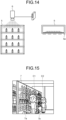
- FIG. 14 is a diagram for explaining the conventional technology.
- the conventional technology uses a camera 6 that is installed above a shelf 5.
- the shelf 5 located on the left side is a front view of the shelf 5, and the shelf 5 on the right side is a top view of the shelf 5.
- a detection line 5a is set in the shelf 5 in advance.
- a video of the camera 6 is analyzed to detect a hand of a person, and when the hand of the person through by the detection line 5a, taking in and out a product is recognized by using an image of a peripheral area of the hand.
- Patent Literature 1 Japanese Laid-open Patent Publication No. 2021-107989
- FIG. 15 is a diagram illustrating an example of an appropriate detection line.
- an appropriate detection line at a position of a person C1 is a detection line 7a of a shelf 7.
- An appropriate detection line at a position of a person C2 is a detection line 7b of the shelf 7. The person moves in front of the shelf 7, and therefore, if a detection line that is set in advance is used as in the conventional technology, taking in and out a product may be erroneously detected.
- a setting program that causes a computer to execute a process, the process including acquiring a video from a camera that is set in a store that has a storage unit in which a product is stored; identifying a depth indicating a distance from the camera to each of constituent elements of the video acquired from the camera, by inputting the acquired video into a machine learning model; generating a three-dimensional in-store model that is configured with the identified depth indicating the distance from the camera to each of the constituent elements of the video; generating skeleton information on a person who moves inside the store from the video acquired from the camera; setting a range and a direction of an aisle in the store in the generated three-dimensional in-store model based on a change in the generated skeleton information; and setting a detection line in the storage unit based on the range and the direction of the aisle in the store, the detection line for detecting that the person has extended a hand to a product.
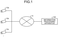
- FIG. 1 is a diagram illustrating a system according to the present embodiment. As illustrated in FIG. 1 , the system includes cameras 10a, 10b, and 10c and an information processing apparatus 100.
- the information processing apparatus 100 is one example of a setting apparatus and a detection apparatus.
- the cameras 10a to 10c and the information processing apparatus 100 are connected to one another via a network 15.
- the cameras 10a to 10c are cameras that are installed in a store that has a storage unit, such as a shelf, in which a product is stored. Each of the cameras 10a to 10c captures a video including a shelf installed in the store, and transmits information on the captured video to the information processing apparatus 100. In the following descriptions, the information on the video will be referred to as "video information”. The video information includes chronological images (still images). The cameras 10a to 10c will be collectively referred to as a "camera 10".
- the information processing apparatus 100 sets a detection line for detecting taking in and out a product that is stored in a shelf, on the basis of the video information received from the camera 10. Further, the information processing apparatus 100 detects taking in and out a product by a user by using the set detection line.
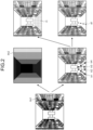
- FIG. 2 and FIG. 3 are diagrams for explaining a process performed by the information processing apparatus according to the present embodiment.
- the information processing apparatus 100 inputs video information Im1 received from the camera 10 to a trained learning model that performs monocular depth estimation, and generates a depth image Im2.
- the depth image Im2 includes a plurality of pixels, and distance information is set in each of the pixels.
- Each of the pixels of the depth image Im2 corresponds to each of pixels at the same coordinate in the video information (image) Im1.
- the distance information that is set in each of the pixels of the depth image Im2 indicates a distance between an in-store area corresponding to the pixel of the video information Im1 and the camera 10.
- the information processing apparatus 100 When the information processing apparatus 100 generates the depth image Im2, it is assumed that the video information Im1 does not include a user. In other words, the information processing apparatus 100 generates the depth image Im2 by using the video information Im1 that is captured by the camera 10 during a time period in which a user is not present.
- the information processing apparatus 100 generates skeleton information on a user who moves inside the store on the basis of the video information Im1, and identifies a movement trajectory on the basis of a change of a foot part in the generated skeleton information.
- the information processing apparatus 100 identifies the movement trajectory, it is assumed that the video information Im1 includes a user. In other words, the information processing apparatus 100 identifies the movement trajectory of the user by using the video information Im1 that is captured by the camera 10 during a time period in which the user is present.
- the information processing apparatus 100 identifies movement trajectories tr1, tr2, tr3, and tr4.
- the information processing apparatus 100 identifies an aisle area f1 and an aisle direction d1 on the basis of the movement trajectories tr1, tr2, tr3, and tr4.
- the information processing apparatus 100 identifies moving ranges of the movement trajectories tr1 to tr4 as the aisle area f1.
- the information processing apparatus 100 identifies a mean vector of displacement vectors of the movement trajectories tr1 to tr4 as the aisle direction d1.
- the information processing apparatus 100 generates an in-store 3D model in a three-dimensional space, on the basis of the depth image Im2, the aisle area f1, and the aisle direction d1. For example, the information processing apparatus 100 converts the distance information on the depth image Im2, a coordinate of the aisle area f1, and a coordinate of the aisle direction d1 into three-dimensional coordinates on the in-store 3D model, and synthesizes the coordinates.
- the information processing apparatus 100 estimates skeleton information on a user C3 on the basis of video information Im3 that includes the user C3, and identifies a position p1 of a foot of the user C3.
- the information processing apparatus 100 converts the position p1 to a position p1' in the in-store 3D model M1.
- the information processing apparatus 100 sets a plane H1 in the in-store 3D model M1 on the basis of the position p1' and the aisle direction d1.
- a segment 11 at a lower edge of the plane H1 passes through the position p1' and is perpendicular to the aisle direction d1.
- the information processing apparatus 100 sets a detection line L10a that connects a point a1 at which the segment 11 and the shelf 8a come into contact with each other and an upper edge b1 of the shelf 8a by using the fact that the shelves 8a and 8b for products are installed so as to be oriented perpendicular to the aisle direction d1.
- the information processing apparatus 100 sets a detection line L10b that connects a point a2 at which the segment 11 and the shelf 8b come into contact with each other and an upper edge b2 of the shelf 8b.
- the information processing apparatus 100 performs the process as described above every time the user C1 moves and the position p1 is changed, and sets the detection lines L10a and L10b again.
- the information processing apparatus 100 calculates a detection line for each of representative positions in advance, obtains, for the position p1, a representative position that is located close to the position p1, and adopts a detection line corresponding to the position p1.
- the information processing apparatus 100 sets a detection line by integrating detection lines of (a plurality of) representative positions located close to the position p1, in accordance with distances between the position p1 and the representative positions.
- the information processing apparatus 100 detects taking in and out a product by the user C3 by using the detection lines L10a and L10b, by using the fact that the user C3 faces the shelf 8a (8b) when taking out a product from the shelf 8a (8b).
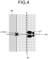
- FIG. 4 is a diagram for complementing the process performed by the information processing apparatus according to the present embodiment.
- FIG. 4 is a top view of the in-store 3D model M1 illustrated in FIG. 3 .
- the shelf 8a for products is installed so as to be oriented perpendicular to the aisle direction d1.
- the segment 11 illustrated in FIG. 3 is perpendicular to the aisle direction d1.
- the information processing apparatus 100 generates the in-store 3D model M1 on the basis of the depth image and the movement trajectory of the user obtained from the video information from the camera 10, sets a detection line of a shelf for each standing position of the user on a floor, and uses the detection line for detection. In this manner, by setting the detection line for each standing position of the user, it is possible to more accurately detect taking in and out a product as compared to a case in which the detection line is set in advance as in the conventional technology.
- FIG. 5 is a diagram for explaining an example of erroneous detection in the conventional technology.
- An image Im4-1 in FIG. 5 includes shelves 9A and 9B, and detection lines L9A and L9B are set in advance.
- the detection line L9A is used to detect taking in and out a product stored in the shelf 9A.
- the detection line L9B is used to detect taking in and out a product stored in the shelf 9B.
- the detection lines L9A and L9B are not set in accordance with a position of a user as in the information processing apparatus 100 of the present embodiment. Therefore, even when a user C4 moves in front of the shelf 9A and does not take in and out a product stored in the shelf 9A, a hand of the user C4 exceeds the detection line L9A, which may lead to erroneous detection.
- An image Im4-2 in FIG. 5 includes a shelf 9C, and, for example, a contour of the shelf is set as a detection line L9C in advance.
- the detection line L9C is used to detect taking in and out a product stored in the shelf 9C.
- the detection line L9C is not set in accordance with a position of a user as in the information processing apparatus 100 of the present embodiment. Therefore, even when a user C5 moves in front of the shelf 9C and does not take in and out a product stored in the shelf 9C, a hand of the user C5 exceeds the detection line L9C, which may lead to erroneous detection.
- FIG. 6 is a functional block diagram illustrating a configuration of the information processing apparatus according to the present embodiment.
- the information processing apparatus 100 includes a communication unit 110, an input unit 120, a display unit 130, a storage unit 140, and a control unit 150.
- the communication unit 110 transmits and receives information to and from the camera 10 via the network 15.
- the communication unit 110 receives the video information from the camera 10.
- the communication unit 110 is implemented by a network interface card (NIC) or the like.
- the input unit 120 is implemented by an input device, such as a keyboard or a mouse, and inputs various kinds of information to the control unit 150 in accordance with input operation performed by an administrator or the like.
- the display unit 130 is implemented by a display device, such as a liquid crystal display.
- the display unit 130 may display a processing result of the control unit 150.
- the storage unit 140 stores therein a video buffer 141, a depth image information 142, a movement trajectory table 143, and the in-store 3D model M1.
- the storage unit 140 is implemented by, for example, a semiconductor memory device, such as a flash memory, or a storage device, such as a hard disk or an optical disk.
- the video buffer 141 is a buffer for storing the video information that is transmitted from the camera 10.
- the video buffer 141 stores therein the video information Im1 illustrated in FIG. 2 , the video information Im3 illustrated in FIG. 3 , and the like.
- the depth image information 142 has a plurality of pixels, and distance information is set for each of the pixels.
- a plurality of pixels of a video (image) corresponds to a plurality of constituent elements.
- the distance information indicates a distance between an in-store area corresponding to the pixel of the video information and the camera 10.
- the depth image information 142 corresponds to the depth image Im2 illustrated in FIG. 2 , or the like.
- the movement trajectory table 143 is a table for storing information on a movement trajectory of a user.
- FIG. 7 is a diagram illustrating an example of a data structure of the movement trajectory table.
- the movement trajectory table 143 associates user identification (ID) with the movement trajectory.
- ID is information for distinguishing a user who is identified from the video information of the camera 10.
- the movement trajectory indicates a movement trajectory of the user who is identified from the video information, and location information is set at predetermined time intervals.
- the in-store 3D model M1 is a three-dimensional in-store model described above with reference to FIG. 3 .
- a three-dimensional coordinate of each of corners of the shelves 8a and 8b, a three-dimensional coordinate of each of corners of the aisle area f1, three-dimensional coordinates of a start point and an end point indicating the aisle direction d1, and the like are defined.
- the control unit 150 includes a receiving unit 151, a depth identification unit 152, a posture estimation unit 153, a movement trajectory calculation unit 154, an aisle estimation unit 155, a detection line setting unit 156, and a determination unit 157.
- the control unit 150 is implemented by a central processing unit (CPU) or a micro processing unit (MPU). Further, the control unit 150 may be implemented by, for example, an integrated circuit, such as an application specific integrated circuit (ASIC) or a field programmable gate array (FPGA).
- ASIC application specific integrated circuit
- FPGA field programmable gate array
- the receiving unit 151 receives video information from the camera 10.
- the receiving unit 151 stores the received video information in the video buffer 141.
- the depth identification unit 152 generates the depth image information 142 by inputting video information that is received from the camera 10 during a time period in which a user is not present in the store into a trained first learning model that performs monocular depth estimation.
- the learning model is trained on the basis of teacher data that uses the video information as an input and uses the distance information at each of the pixels of the video information as a correct answer label.
- the depth identification unit 152 stores the depth image information 142 in the storage unit 140.
- the posture estimation unit 153 estimates the skeleton information on a user by inputting video information that is received from the camera 10 during a time period in which the user is present in the store into a trained second learning model. For example, the posture estimation unit 153 sequentially inputs chronological images included in the video information into the second learning model, and sequentially estimates pieces of skeleton information in the respective images. The posture estimation unit 153 outputs the pieces of chronological skeleton information to the movement trajectory calculation unit 154.
- the posture estimation unit 153 outputs the pieces of chronological skeleton information to the detection line setting unit 156 and the determination unit 157.
- the second learning model is a trained machine learning model that inputs an image including an area of the user and outputs the skeleton information.
- the second learning model is constructed by using an existing algorithm, such as DeepPose or OpenPose.
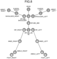
- FIG. 8 is a diagram illustrating an example of the skeleton information.
- the skeleton information 18 pieces of definition information (with the numbers 0 to 17) in each of which a joint identified by a well-known skeleton model is assigned with a number may be used.
- a right shoulder joint (SHOULDER_RIGHT) is assigned with the number 8
- a left elbow joint (ELBOW_LEFT) is assigned with the number 5
- a left knee joint (KNEE_LEFT) is assigned with the number 11
- the X axis may be defined as a horizontal direction of an image and the Y axis may be defined as a vertical direction of the image.
- the movement trajectory calculation unit 154 calculates the movement trajectory of the user on the basis of changes of the pieces of chronological skeleton information acquired from the posture estimation unit 153.
- the movement trajectory calculation unit 154 assigns the user ID to the movement trajectory and stores the user ID in association with information on the movement trajectory of the user in the movement trajectory table 143.
- the movement trajectory calculation unit 154 identifies a position of a foot in the pieces of chronological skeleton information, and calculates a temporal change of the position of the foot (for example, two-dimensional coordinate) as the movement trajectory.
- the position of the foot in the skeleton information may be the coordinate with the number 17 (FOOT_RIGHT), the coordinate with the number 13 (FOOT_LEFT), an average of the coordinates with the numbers 17 and 13, or the like in the pieces of skeleton information illustrated in FIG. 8 .
- the movement trajectory calculation unit 154 may estimate the position of the foot from each of the joints in the pieces of other observed skeleton information, and adopt the estimated position as the position of the foot.
- the aisle estimation unit 155 estimates the aisle area and the aisle direction on the basis of the information on each of movement trajectories stored in the movement trajectory table 143.
- the aisle estimation unit 155 outputs the information on the estimated aisle area and the estimated aisle direction to the detection line setting unit 156.
- the aisle estimation unit 155 calculates a polygon including the position of the foot in each of the movement trajectories, and estimates the calculated polygon as the position of the aisle area. For example, the information on the aisle area estimated by the aisle estimation unit 155 corresponding to the aisle area f1 illustrated in FIG. 2 .
- a mean vector of displacement vectors of the foot in the plurality of movement trajectories is estimated as the aisle direction.
- the information on the aisle direction estimated by the aisle estimation unit 155 corresponds to the aisle direction d1 illustrated in FIG. 2 .
- the detection line setting unit 156 sets, on the shelf, a detection line for detecting that a user has extended a hand to a product. For example, the detection line setting unit 156 performs a process of generating the in-store 3D model M1 and thereafter performs a process of setting the detection line.
- the detection line setting unit 156 generates the in-store 3D model M1 for a three-dimensional space on the basis of the depth image information 142, the aisle area f1, and the aisle direction d1.
- the detection line setting unit 156 converts the distance information on the depth image information 142 into a three-dimensional coordinate in the in-store 3D model M1 on the basis of the distance information on the depth image information 142 and a first definition table.
- the first definition table is a table in which a relationship between the distance information and the three-dimensional coordinate in the in-store 3D model M1 is defined.
- the detection line setting unit 156 converts the coordinate of the aisle area f1 and the coordinate of the aisle direction d1 into three-dimensional coordinates in the in-store 3D model M1 on the basis of the coordinate of the aisle area f1, the coordinate of the aisle direction d1, and a second definition table.
- the second definition table is a table in which a relationship among the coordinate of the aisle area f1, the coordinate of the aisle direction d1, and the three-dimensional coordinates in the in-store 3D model M1 is defined.
- the detection line setting unit 156 identifies, as a shelf, an object that is located in an area other than the aisle area f1 among objects that are located in the in-store 3D model M1 obtained from the distance information on the depth image information 142.
- the detection line setting unit 156 identifies, as the shelves 8a and 8b, objects other than the aisle area f1 in the in-store 3D model M1.
- the detection line setting unit 156 acquires the skeleton information from the posture estimation unit 153, and calculates the position of the foot (the three-dimensional coordinate) of the user. For example, it is assumed that the position of the foot calculated by the detection line setting unit 156 is the position p1' as illustrated in FIG. 3 .
- the detection line setting unit 156 arranges the plane H1 in the in-store 3D model M1 such that the segment 11 at the lower edge of the plane H1 passes through the position p1' and is located perpendicular to the aisle direction d1.
- the coordinate of each of the joints in the pieces of skeleton information estimated by the posture estimation unit 153 is a two-dimensional coordinate
- the detection line setting unit 156 calculates a three-dimensional coordinate by using a conversion table for converting a two-dimensional coordinate into a three-dimensional coordinate, or the like.
- the detection line setting unit 156 sets the detection line L10a that connects the point a1 at which the segment 11 and the shelf 8a come into contact with each other and the upper edge b1 of the shelf 8a, with respect to the shelves 8a and 8b for products.
- the detection line setting unit 156 sets the detection line L10b that connects the point a2 at which the segment 11 and the shelf 8b come into contact with each other and the upper edge b2 of the shelf 8b.
- the detection line setting unit 156 outputs information on the detection lines L10a and L10b that are set as described above to the determination unit 157.
- the detection line setting unit 156 performs the above-described process every time the user moves and the position p1' is changed, sets -set the detection lines L10a and L10b again, and outputs information on the re-set detection lines L10a and L10b to the determination unit 157.
- the determination unit 157 detects that the user has extended a hand to a product on the basis of the detection line acquired from the detection line setting unit 156, and determines whether the user has taken out the product from the shelf.
- One example of a process performed by the determination unit 157 will be described below.
- the determination unit 157 acquires the skeleton information from the posture estimation unit 153, and calculates the position of the hand of the user (two-dimensional coordinate). For example, the determination unit 157 calculates, as the position of the hand of the user, the coordinate with the number 6 (WRIST_RIGHT) or the coordinate with the number 9 (WRIST_LEFT) in the pieces of skeleton information illustrated in FIG. 8 .
- the coordinate with the number 6 (WRIST_RIGHT) will be referred to as a position of a right hand.
- the coordinate with the number 9 (WRIST_LEFT) will be referred to as a position of a left hand.
- the determination unit 157 compares the position of the detection line L10a, the position of the right hand, and the position of the left hand, and adopts one of the right hand and the left hand closer to the position of the detection line L10a as a hand of interest. In this example, explanation will be given based on the assumption that the right hand is adopted as the hand of interest.
- the determination unit 157 calculates a distance between the position of the detection line L10a and the position of the right hand, and determines that the user has extended the hand to the product on the shelf if the distance is smaller than a threshold. If it is determined that the user has extended the hand to the product on the shelf, the determination unit 157 detects an action of taking out the product by the user through a process as described below.
- FIG. 9 is a diagram for explaining a process of detecting the action of taking out a product.
- the determination unit 157 acquires an image (video information) of an area 25 that is set near the detection line L10a from the video buffer 141. As described above, the position of the detection line L10a is changed depending on the position of the user C1, and therefore, it is assumed that a position of the area 25 is dynamically changed depending on the position of the detection line L10a.
- the determination unit 157 determines whether the product is present in the hand of the user C1 by using an identification model 26.
- the identification model 26 is a model for identifying whether the product is present in the hand of the user, and may be a learning model based on Human Object Interaction Detection (HOID) or the like.
- the determination unit 157 detects that the user C1 has performed the action of taking out the product.
- the determination unit 157 detects that the user C1 has performed the action of returning the product.
- the determination unit 157 may compare an image (background image) that is obtained before the user C appears and a current image to improve image recognition accuracy.
- FIG. 10 is a diagram for explaining another process performed by the determination unit.
- the determination unit 157 when extracting an input image Im5-1 (video information) from the video buffer 141 and performing image processing, the determination unit 157 generates a foreground mask Im5-3 by subtracting a background image Im5-2 that is prepared in advance from the input image Im5-1.
- the determination unit 157 compares the input image Im5-1 and the foreground mask Im5-3, and generates an image Im5-4 in which an area other than an area of a mask A1 is extracted.
- the image Im5-4 does not include a background image, so that it is possible to improve accuracy in executing the detection process as described above with reference to FIG. 9 .
- FIG. 11 is a flowchart illustrating a pre-setting process performed by the information processing apparatus.
- the receiving unit 151 of the information processing apparatus 100 receives video information from the camera 10, and stores the video information in the video buffer 141 (Step S101).
- the depth identification unit 152 of the information processing apparatus 100 inputs the video information into the first learning model, and generates the depth image information 142 (Step S102).
- the posture estimation unit 153 of the information processing apparatus 100 inputs the video information into the second learning model, and generates the skeleton information (Step S103).
- the movement trajectory calculation unit 154 of the information processing apparatus 100 generates the information on the movement trajectory on the basis of the chronological skeleton information, and stores the information on the movement trajectory in the movement trajectory table 143 (Step S104).
- the aisle estimation unit 155 of the information processing apparatus 100 estimates the aisle area and the aisle direction on the basis of the information on the movement trajectory stored in the movement trajectory table 143 (Step S105).
- the detection line setting unit 156 of the information processing apparatus 100 generates the in-store 3D model M1 on the basis of the depth image information 142, the aisle area, and the aisle direction (Step S106).
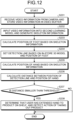
- FIG. 12 is a flowchart illustrating the detection process performed by the information processing apparatus.
- the receiving unit 151 of the information processing apparatus 100 receives video information from the camera 10, and stores the video information in the video buffer 141 (Step S201).
- the posture estimation unit 153 of the information processing apparatus 100 inputs the video information into the second learning model, and generates the skeleton information (Step S202).
- the detection line setting unit 156 of the information processing apparatus 100 calculates a position of a foot on the basis of the skeleton information (Step S203).
- the detection line setting unit 156 sets the detection line on the basis of the in-store 3D model M1 and the position of the foot (Step S204).
- the determination unit 157 of the information processing apparatus 100 calculates a position of a hand on the basis of the skeleton information (Step S205).
- the determination unit 157 calculates a distance between the position of the detection line and the position of the hand (Step S206). If the distance is smaller than a threshold (Yes at Step S207), the determination unit 157 determines that the user has extended the hand to a product on the shelf, and detects an action of taking out the product (Step S208).
- the determination unit 157 terminates the process.
- the information processing apparatus 100 generates the in-store 3D model M1 on the basis of the depth image information 142 and the movement trajectory of the user, which are obtained from the video information of the camera 10, sets a detection line of a shelf for each standing position of the user on a floor, and uses the detection line for detection. In this manner, by setting the detection line for each standing position of the user, it is possible to detect taking in and out a product with high accuracy as compared to a case in which the detection line is set in advance as in the conventional technology.
- the information processing apparatus 100 identifies a change of the position of the foot of the user on the basis of the pieces of chronological skeleton information on the user, and identifies, as an aisle area, a polygon in which the identified change of the position of the foot is included. With this configuration, it is possible to identify three-dimensional positions of the aisle area and the shelf in the in-store 3D model M1.
- the information processing apparatus 100 identifies a change of the position of the foot of the user on the basis of the pieces of chronological skeleton information on the user, and identifies the aisle direction on the basis of the displacement directional vector based on the identified position of the foot. By arranging a plane that crosses the identified aisle direction at a right angle in the in-store 3D model M1, it is possible to set the detection line with high accuracy.
- the information processing apparatus 100 sets the detection line for each standing position of the user, identifies a part corresponding to a hand of the user on the basis of the skeleton information on the user, and detects that the user has extended the hand to a product stored in the shelf, on the basis of a positional relationship between the detection line and the part of the hand. With this configuration, it is possible to detect the action of taking out the product from the user.
- the information processing apparatus 100 it is possible to set the detection line by setting the in-store 3D model M1 in advance and identifying only the position of the foot of the user, so that it is possible to reduce a processing load of the information processing apparatus 100. Moreover, it is possible to detect the action of taking out a product from the shelf by the user without using a high-definition camera.
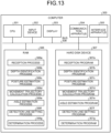
- FIG. 13 is a diagram illustrating an example of the hardware configuration of the computer that implements the same functions as those of the information processing apparatus of one embodiment.
- a computer 300 includes a CPU 301 that performs various kinds of arithmetic processing, an input device 302 that receives input of data from a user, and a display 303. Furthermore, the computer 300 includes a communication apparatus 304 that transmits and receives data to and from an external apparatus or the like via a wired or wireless network, and an interface apparatus 305. Moreover, the computer 300 includes a random access memory (RAM) 306 for temporarily storing various kinds of information, and a hard disk device 307. Furthermore, all of the devices 301 to 307 are connected to a bus 308.
- RAM random access memory
- the hard disk device 307 includes a reception program 307a, a depth identification program 307b, a posture estimation program 307c, a movement trajectory calculation program 307d, and an aisle estimation program 307e.
- the hard disk device 307 further includes a detection line setting program 307f and a determination program 307g. Furthermore, the CPU 301 reads each of the programs 307a to 307g and loads the programs 307a to 307g onto the RAM 306.
- the reception program 307a functions as a reception process 306a.
- the depth identification program 307b functions as a depth identification process 306b.
- the posture estimation program 307c functions as a posture estimation process 306c.
- the movement trajectory calculation program 307d functions as a movement trajectory calculation process 306d.
- the aisle estimation program 307e functions as an aisle estimation process 306e.
- the detection line setting program 307f functions as a detection line setting process 306f.
- the determination program 307g functions as a determination process 306g.
- a process of the reception process 306a corresponds to the process performed by the receiving unit 151.
- a process of the depth identification process 306b corresponds to the process performed by the depth identification unit 152.
- a process of the posture estimation process 306c corresponds to the process performed by the posture estimation unit 153.
- a process of the movement trajectory calculation process 306d corresponds to the process performed by the movement trajectory calculation unit 154.
- a process of the aisle estimation process 306e corresponds to the process performed by the aisle estimation unit 155.
- a process of the detection line setting process 306f corresponds to the process performed by the detection line setting unit 156.
- a process of the determination process 306g corresponds to the process performed by the determination unit 157.
- each of the programs 307a to 307g need not always be stored in the hard disk device 307 from the beginning.
- each of the programs may be stored in a "portable physical medium", such as a flexible disk (FD), a compact disk-ROM (CD-ROM), a digital versatile disk (DVD), a magneto optical disk, or an integrated circuit (IC) card, which is inserted into the computer 300.
- the computer 300 may read and execute each of the programs 307a to 307g.
Landscapes
- Engineering & Computer Science (AREA)
- Theoretical Computer Science (AREA)
- Physics & Mathematics (AREA)
- General Physics & Mathematics (AREA)
- Computer Vision & Pattern Recognition (AREA)
- Multimedia (AREA)
- Health & Medical Sciences (AREA)
- General Health & Medical Sciences (AREA)
- Software Systems (AREA)
- Artificial Intelligence (AREA)
- Geometry (AREA)
- Computing Systems (AREA)
- Databases & Information Systems (AREA)
- Evolutionary Computation (AREA)
- Computer Graphics (AREA)
- Medical Informatics (AREA)
- Psychiatry (AREA)
- Social Psychology (AREA)
- Human Computer Interaction (AREA)
- Image Analysis (AREA)
Abstract
Description
- The embodiment discussed herein is related to a non-transitory computer readable recording medium and the like.
- In recent year, a technology for recognizing taking in and out a product with respect to a product shelf (shelf) by a customer in a store is attracting attention. With use of the technology, it becomes possible to introduce self-checkout or detect shoplifting, for example. The technology for recognizing taking in and out a product includes a method of using a camera and an image recognition technique, a method of adding Radio Frequency Identification (RFID) to each of products, a method of installing a weight sensor for each of shelves, and the like.
- The method of using a camera and the image recognition technique has the advantage of being easily introducible as compared to the method of adding RFID to each of products and the method of installing a weight sensor for each of shelves. Further, in the method of using a camera and the image recognition technique, it is possible to suppress additional cost by using an existing monitoring camera, so that the method is in high demand.
- One example of the conventional technology for recognizing taking in and out a product using a camera and the image recognition technique will be described below.
FIG. 14 is a diagram for explaining the conventional technology. The conventional technology uses acamera 6 that is installed above ashelf 5. Theshelf 5 located on the left side is a front view of theshelf 5, and theshelf 5 on the right side is a top view of theshelf 5. In the conventional technology, adetection line 5a is set in theshelf 5 in advance. - In the conventional technology, a video of the
camera 6 is analyzed to detect a hand of a person, and when the hand of the person through by thedetection line 5a, taking in and out a product is recognized by using an image of a peripheral area of the hand. - Patent Literature 1:
Japanese Laid-open Patent Publication No. 2021-107989 - However, in the conventional technology as described above, there is a problem in that taking in and out a product is erroneously detected.
- For example, when a monitoring camera is used, a positional relationship between a camera and a shelf is different for each combination of the camera and the shelf, and therefore, it is difficult to use the detection line that is uniformly defined in advance as in the conventional technology.
- In particular, depending on imaging conditions, an appropriate detection line may be different even in the same shelf, depending on a position of a person.
FIG. 15 is a diagram illustrating an example of an appropriate detection line. For example, an appropriate detection line at a position of a person C1 is adetection line 7a of ashelf 7. An appropriate detection line at a position of a person C2 is adetection line 7b of theshelf 7. The person moves in front of theshelf 7, and therefore, if a detection line that is set in advance is used as in the conventional technology, taking in and out a product may be erroneously detected. - Accordingly, it is an object in one aspect of an embodiment of the present invention to provide a setting program, a detection program, a setting method, and a setting apparatus capable of detecting taking in and out a product.
- According to an aspect of an embodiment, a setting program that causes a computer to execute a process, the process including acquiring a video from a camera that is set in a store that has a storage unit in which a product is stored; identifying a depth indicating a distance from the camera to each of constituent elements of the video acquired from the camera, by inputting the acquired video into a machine learning model; generating a three-dimensional in-store model that is configured with the identified depth indicating the distance from the camera to each of the constituent elements of the video; generating skeleton information on a person who moves inside the store from the video acquired from the camera; setting a range and a direction of an aisle in the store in the generated three-dimensional in-store model based on a change in the generated skeleton information; and setting a detection line in the storage unit based on the range and the direction of the aisle in the store, the detection line for detecting that the person has extended a hand to a product.
-
-
FIG. 1 is a diagram illustrating a system according to the present embodiment; -
FIG. 2 is a first diagram for explaining a process performed by an information processing apparatus according to the present embodiment; -
FIG. 3 is a second diagram for explaining the process performed by the information processing apparatus according to the present embodiment; -
FIG. 4 is a diagram for complementing the process performed by the information processing apparatus according to the present embodiment; -
FIG. 5 is a diagram for explaining an example of erroneous detection in the conventional technology; -
FIG. 6 is a functional block diagram illustrating a configuration of the information processing apparatus according to the present embodiment; -
FIG. 7 is a diagram illustrating an example of a data structure of a movement trajectory table; -
FIG. 8 is a diagram illustrating an example of skeleton information; -
FIG. 9 is a diagram for explaining a process of detecting an action of taking out a product; -
FIG. 10 is a diagram for explaining another process performed by a determination unit; -
FIG. 11 is a flowchart illustrating a pre-setting process performed by the information processing apparatus; -
FIG. 12 is a flowchart of a detection process performed by the information processing apparatus; -
FIG. 13 is a diagram illustrating an example of a hardware configuration of a computer that implements the same functions as those of the information processing apparatus of one embodiment; -
FIG. 14 is a diagram for explaining the conventional technology; and -
FIG. 15 is a diagram illustrating an example of an appropriate detection line. - Preferred embodiments of the present invention will be explained with reference to accompanying drawings. The present invention is not limited by the embodiments below.
-
FIG. 1 is a diagram illustrating a system according to the present embodiment. As illustrated inFIG. 1 , the system includescameras information processing apparatus 100. Theinformation processing apparatus 100 is one example of a setting apparatus and a detection apparatus. Thecameras 10a to 10c and theinformation processing apparatus 100 are connected to one another via anetwork 15. - The
cameras 10a to 10c are cameras that are installed in a store that has a storage unit, such as a shelf, in which a product is stored. Each of thecameras 10a to 10c captures a video including a shelf installed in the store, and transmits information on the captured video to theinformation processing apparatus 100. In the following descriptions, the information on the video will be referred to as "video information". The video information includes chronological images (still images). Thecameras 10a to 10c will be collectively referred to as a "camera 10". - The
information processing apparatus 100 sets a detection line for detecting taking in and out a product that is stored in a shelf, on the basis of the video information received from thecamera 10. Further, theinformation processing apparatus 100 detects taking in and out a product by a user by using the set detection line. -
FIG. 2 andFIG. 3 are diagrams for explaining a process performed by the information processing apparatus according to the present embodiment. First,FIG. 2 will be described. Theinformation processing apparatus 100 inputs video information Im1 received from thecamera 10 to a trained learning model that performs monocular depth estimation, and generates a depth image Im2. The depth image Im2 includes a plurality of pixels, and distance information is set in each of the pixels. Each of the pixels of the depth image Im2 corresponds to each of pixels at the same coordinate in the video information (image) Im1. The distance information that is set in each of the pixels of the depth image Im2 indicates a distance between an in-store area corresponding to the pixel of the video information Im1 and thecamera 10. - When the
information processing apparatus 100 generates the depth image Im2, it is assumed that the video information Im1 does not include a user. In other words, theinformation processing apparatus 100 generates the depth image Im2 by using the video information Im1 that is captured by thecamera 10 during a time period in which a user is not present. - The
information processing apparatus 100 generates skeleton information on a user who moves inside the store on the basis of the video information Im1, and identifies a movement trajectory on the basis of a change of a foot part in the generated skeleton information. When theinformation processing apparatus 100 identifies the movement trajectory, it is assumed that the video information Im1 includes a user. In other words, theinformation processing apparatus 100 identifies the movement trajectory of the user by using the video information Im1 that is captured by thecamera 10 during a time period in which the user is present. - In the example illustrated in
FIG. 2 , a case is illustrated in which theinformation processing apparatus 100 identifies movement trajectories tr1, tr2, tr3, and tr4. Theinformation processing apparatus 100 identifies an aisle area f1 and an aisle direction d1 on the basis of the movement trajectories tr1, tr2, tr3, and tr4. For example, theinformation processing apparatus 100 identifies moving ranges of the movement trajectories tr1 to tr4 as the aisle area f1. Theinformation processing apparatus 100 identifies a mean vector of displacement vectors of the movement trajectories tr1 to tr4 as the aisle direction d1. - The
information processing apparatus 100 generates an in-store 3D model in a three-dimensional space, on the basis of the depth image Im2, the aisle area f1, and the aisle direction d1. For example, theinformation processing apparatus 100 converts the distance information on the depth image Im2, a coordinate of the aisle area f1, and a coordinate of the aisle direction d1 into three-dimensional coordinates on the in-store 3D model, and synthesizes the coordinates. - Explanation on
FIG. 3 will be given below. For example, as illustrated inFIG. 3 ,shelves store 3D model M1. Theinformation processing apparatus 100 estimates skeleton information on a user C3 on the basis of video information Im3 that includes the user C3, and identifies a position p1 of a foot of the user C3. - The
information processing apparatus 100 converts the position p1 to a position p1' in the in-store 3D model M1. Theinformation processing apparatus 100 sets a plane H1 in the in-store 3D model M1 on the basis of the position p1' and the aisle direction d1. Asegment 11 at a lower edge of the plane H1 passes through the position p1' and is perpendicular to the aisle direction d1. - The
information processing apparatus 100 sets a detection line L10a that connects a point a1 at which thesegment 11 and theshelf 8a come into contact with each other and an upper edge b1 of theshelf 8a by using the fact that theshelves information processing apparatus 100 sets a detection line L10b that connects a point a2 at which thesegment 11 and theshelf 8b come into contact with each other and an upper edge b2 of theshelf 8b. Theinformation processing apparatus 100 performs the process as described above every time the user C1 moves and the position p1 is changed, and sets the detection lines L10a and L10b again. For example, theinformation processing apparatus 100 calculates a detection line for each of representative positions in advance, obtains, for the position p1, a representative position that is located close to the position p1, and adopts a detection line corresponding to the position p1. Alternatively, theinformation processing apparatus 100 sets a detection line by integrating detection lines of (a plurality of) representative positions located close to the position p1, in accordance with distances between the position p1 and the representative positions. - The
information processing apparatus 100 detects taking in and out a product by the user C3 by using the detection lines L10a and L10b, by using the fact that the user C3 faces theshelf 8a (8b) when taking out a product from theshelf 8a (8b). -
FIG. 4 is a diagram for complementing the process performed by the information processing apparatus according to the present embodiment.FIG. 4 is a top view of the in-store 3D model M1 illustrated inFIG. 3 . As illustrated inFIG. 4 , theshelf 8a for products is installed so as to be oriented perpendicular to the aisle direction d1. For example, when the user stands at the position p1' and takes out a product from theshelf 8a, the user faces theshelf 8a. In other words, thesegment 11 illustrated inFIG. 3 is perpendicular to the aisle direction d1. - As described above, the
information processing apparatus 100 generates the in-store 3D model M1 on the basis of the depth image and the movement trajectory of the user obtained from the video information from thecamera 10, sets a detection line of a shelf for each standing position of the user on a floor, and uses the detection line for detection. In this manner, by setting the detection line for each standing position of the user, it is possible to more accurately detect taking in and out a product as compared to a case in which the detection line is set in advance as in the conventional technology. -
FIG. 5 is a diagram for explaining an example of erroneous detection in the conventional technology. An image Im4-1 inFIG. 5 includesshelves shelf 9A. The detection line L9B is used to detect taking in and out a product stored in theshelf 9B. As for the detection lines L9A and L9B, the detection lines L9A and L9B are not set in accordance with a position of a user as in theinformation processing apparatus 100 of the present embodiment. Therefore, even when a user C4 moves in front of theshelf 9A and does not take in and out a product stored in theshelf 9A, a hand of the user C4 exceeds the detection line L9A, which may lead to erroneous detection. - An image Im4-2 in
FIG. 5 includes ashelf 9C, and, for example, a contour of the shelf is set as a detection line L9C in advance. The detection line L9C is used to detect taking in and out a product stored in theshelf 9C. As for the detection line L9C, the detection line L9C is not set in accordance with a position of a user as in theinformation processing apparatus 100 of the present embodiment. Therefore, even when a user C5 moves in front of theshelf 9C and does not take in and out a product stored in theshelf 9C, a hand of the user C5 exceeds the detection line L9C, which may lead to erroneous detection. - A configuration example of the
information processing apparatus 100 according to the present embodiment will be described below.FIG. 6 is a functional block diagram illustrating a configuration of the information processing apparatus according to the present embodiment. As illustrated inFIG. 6 , theinformation processing apparatus 100 includes a communication unit 110, aninput unit 120, a display unit 130, astorage unit 140, and acontrol unit 150. - The communication unit 110 transmits and receives information to and from the
camera 10 via thenetwork 15. The communication unit 110 receives the video information from thecamera 10. For example, the communication unit 110 is implemented by a network interface card (NIC) or the like. - The
input unit 120 is implemented by an input device, such as a keyboard or a mouse, and inputs various kinds of information to thecontrol unit 150 in accordance with input operation performed by an administrator or the like. - The display unit 130 is implemented by a display device, such as a liquid crystal display. For example, the display unit 130 may display a processing result of the
control unit 150. - The
storage unit 140 stores therein a video buffer 141, a depth image information 142, a movement trajectory table 143, and the in-store 3D model M1. Thestorage unit 140 is implemented by, for example, a semiconductor memory device, such as a flash memory, or a storage device, such as a hard disk or an optical disk. - The video buffer 141 is a buffer for storing the video information that is transmitted from the
camera 10. For example, the video buffer 141 stores therein the video information Im1 illustrated inFIG. 2 , the video information Im3 illustrated inFIG. 3 , and the like. - The depth image information 142 has a plurality of pixels, and distance information is set for each of the pixels. A plurality of pixels of a video (image) corresponds to a plurality of constituent elements. The distance information indicates a distance between an in-store area corresponding to the pixel of the video information and the
camera 10. The depth image information 142 corresponds to the depth image Im2 illustrated inFIG. 2 , or the like. - The movement trajectory table 143 is a table for storing information on a movement trajectory of a user.
FIG. 7 is a diagram illustrating an example of a data structure of the movement trajectory table. As illustrated inFIG. 7 , the movement trajectory table 143 associates user identification (ID) with the movement trajectory. The user ID is information for distinguishing a user who is identified from the video information of thecamera 10. The movement trajectory indicates a movement trajectory of the user who is identified from the video information, and location information is set at predetermined time intervals. - The in-
store 3D model M1 is a three-dimensional in-store model described above with reference toFIG. 3 . For example, in the in-store 3D model M1, a three-dimensional coordinate of each of corners of theshelves - Referring back to explanation of
FIG. 6 , thecontrol unit 150 includes a receivingunit 151, adepth identification unit 152, aposture estimation unit 153, a movementtrajectory calculation unit 154, anaisle estimation unit 155, a detectionline setting unit 156, and adetermination unit 157. Thecontrol unit 150 is implemented by a central processing unit (CPU) or a micro processing unit (MPU). Further, thecontrol unit 150 may be implemented by, for example, an integrated circuit, such as an application specific integrated circuit (ASIC) or a field programmable gate array (FPGA). - The receiving
unit 151 receives video information from thecamera 10. The receivingunit 151 stores the received video information in the video buffer 141. - The
depth identification unit 152 generates the depth image information 142 by inputting video information that is received from thecamera 10 during a time period in which a user is not present in the store into a trained first learning model that performs monocular depth estimation. For example, the learning model is trained on the basis of teacher data that uses the video information as an input and uses the distance information at each of the pixels of the video information as a correct answer label. Thedepth identification unit 152 stores the depth image information 142 in thestorage unit 140. - The
posture estimation unit 153 estimates the skeleton information on a user by inputting video information that is received from thecamera 10 during a time period in which the user is present in the store into a trained second learning model. For example, theposture estimation unit 153 sequentially inputs chronological images included in the video information into the second learning model, and sequentially estimates pieces of skeleton information in the respective images. Theposture estimation unit 153 outputs the pieces of chronological skeleton information to the movementtrajectory calculation unit 154. - Meanwhile, at the time of recognition for detecting whether the user extends his/her hand to a product, the
posture estimation unit 153 outputs the pieces of chronological skeleton information to the detectionline setting unit 156 and thedetermination unit 157. - For example, the second learning model is a trained machine learning model that inputs an image including an area of the user and outputs the skeleton information. For example, the second learning model is constructed by using an existing algorithm, such as DeepPose or OpenPose.
FIG. 8 is a diagram illustrating an example of the skeleton information. As the skeleton information, 18 pieces of definition information (with the numbers 0 to 17) in each of which a joint identified by a well-known skeleton model is assigned with a number may be used. For example, a right shoulder joint (SHOULDER_RIGHT) is assigned with the number 8, a left elbow joint (ELBOW_LEFT) is assigned with thenumber 5, a left knee joint (KNEE_LEFT) is assigned with thenumber 11, and a right hip joint (HIP_RIGHT) is assigned with thenumber 14. Therefore, it is possible to acquire coordinate information on 18 skeletons as illustrated inFIG. 8 from the image data, and, for example, "X coordinate = X7 and Y coordinate = Y7 " is acquired as a position of the right shoulder joint with thenumber 7. Meanwhile, the X axis may be defined as a horizontal direction of an image and the Y axis may be defined as a vertical direction of the image. - The movement
trajectory calculation unit 154 calculates the movement trajectory of the user on the basis of changes of the pieces of chronological skeleton information acquired from theposture estimation unit 153. The movementtrajectory calculation unit 154 assigns the user ID to the movement trajectory and stores the user ID in association with information on the movement trajectory of the user in the movement trajectory table 143. For example, the movementtrajectory calculation unit 154 identifies a position of a foot in the pieces of chronological skeleton information, and calculates a temporal change of the position of the foot (for example, two-dimensional coordinate) as the movement trajectory. The position of the foot in the skeleton information may be the coordinate with the number 17 (FOOT_RIGHT), the coordinate with the number 13 (FOOT_LEFT), an average of the coordinates with the numbers 17 and 13, or the like in the pieces of skeleton information illustrated inFIG. 8 . - Meanwhile, if the position of the foot is not observed, the movement
trajectory calculation unit 154 may estimate the position of the foot from each of the joints in the pieces of other observed skeleton information, and adopt the estimated position as the position of the foot. - The
aisle estimation unit 155 estimates the aisle area and the aisle direction on the basis of the information on each of movement trajectories stored in the movement trajectory table 143. Theaisle estimation unit 155 outputs the information on the estimated aisle area and the estimated aisle direction to the detectionline setting unit 156. - One example of a process of estimating the aisle area by the
aisle estimation unit 155 will be described below. Theaisle estimation unit 155 calculates a polygon including the position of the foot in each of the movement trajectories, and estimates the calculated polygon as the position of the aisle area. For example, the information on the aisle area estimated by theaisle estimation unit 155 corresponding to the aisle area f1 illustrated inFIG. 2 . - One example of a process of estimating the aisle direction by the
aisle estimation unit 155 will be described below. A mean vector of displacement vectors of the foot in the plurality of movement trajectories is estimated as the aisle direction. For example, the information on the aisle direction estimated by theaisle estimation unit 155 corresponds to the aisle direction d1 illustrated inFIG. 2 . - The detection
line setting unit 156 sets, on the shelf, a detection line for detecting that a user has extended a hand to a product. For example, the detectionline setting unit 156 performs a process of generating the in-store 3D model M1 and thereafter performs a process of setting the detection line. - One example of the process of generating the in-
store 3D model M1 by the detectionline setting unit 156 will be described below. The detectionline setting unit 156 generates the in-store 3D model M1 for a three-dimensional space on the basis of the depth image information 142, the aisle area f1, and the aisle direction d1. - For example, the detection
line setting unit 156 converts the distance information on the depth image information 142 into a three-dimensional coordinate in the in-store 3D model M1 on the basis of the distance information on the depth image information 142 and a first definition table. The first definition table is a table in which a relationship between the distance information and the three-dimensional coordinate in the in-store 3D model M1 is defined. - The detection
line setting unit 156 converts the coordinate of the aisle area f1 and the coordinate of the aisle direction d1 into three-dimensional coordinates in the in-store 3D model M1 on the basis of the coordinate of the aisle area f1, the coordinate of the aisle direction d1, and a second definition table. The second definition table is a table in which a relationship among the coordinate of the aisle area f1, the coordinate of the aisle direction d1, and the three-dimensional coordinates in the in-store 3D model M1 is defined. - For example, the detection
line setting unit 156 identifies, as a shelf, an object that is located in an area other than the aisle area f1 among objects that are located in the in-store 3D model M1 obtained from the distance information on the depth image information 142. In the example illustrated inFIG. 3 , the detectionline setting unit 156 identifies, as theshelves store 3D model M1. - One example of the process of setting the detection line by the detection
line setting unit 156 will be described below. For example, at the time of recognition for detecting whether the user has extended a hand to a product, the detectionline setting unit 156 acquires the skeleton information from theposture estimation unit 153, and calculates the position of the foot (the three-dimensional coordinate) of the user. For example, it is assumed that the position of the foot calculated by the detectionline setting unit 156 is the position p1' as illustrated inFIG. 3 . The detectionline setting unit 156 arranges the plane H1 in the in-store 3D model M1 such that thesegment 11 at the lower edge of the plane H1 passes through the position p1' and is located perpendicular to the aisle direction d1. For example, the coordinate of each of the joints in the pieces of skeleton information estimated by theposture estimation unit 153 is a two-dimensional coordinate, and the detectionline setting unit 156 calculates a three-dimensional coordinate by using a conversion table for converting a two-dimensional coordinate into a three-dimensional coordinate, or the like. - The detection
line setting unit 156 sets the detection line L10a that connects the point a1 at which thesegment 11 and theshelf 8a come into contact with each other and the upper edge b1 of theshelf 8a, with respect to theshelves line setting unit 156 sets the detection line L10b that connects the point a2 at which thesegment 11 and theshelf 8b come into contact with each other and the upper edge b2 of theshelf 8b. The detectionline setting unit 156 outputs information on the detection lines L10a and L10b that are set as described above to thedetermination unit 157. - The detection
line setting unit 156 performs the above-described process every time the user moves and the position p1' is changed, sets -set the detection lines L10a and L10b again, and outputs information on the re-set detection lines L10a and L10b to thedetermination unit 157. - The
determination unit 157 detects that the user has extended a hand to a product on the basis of the detection line acquired from the detectionline setting unit 156, and determines whether the user has taken out the product from the shelf. One example of a process performed by thedetermination unit 157 will be described below. - The
determination unit 157 acquires the skeleton information from theposture estimation unit 153, and calculates the position of the hand of the user (two-dimensional coordinate). For example, thedetermination unit 157 calculates, as the position of the hand of the user, the coordinate with the number 6 (WRIST_RIGHT) or the coordinate with the number 9 (WRIST_LEFT) in the pieces of skeleton information illustrated inFIG. 8 . In the following descriptions, the coordinate with the number 6 (WRIST_RIGHT) will be referred to as a position of a right hand. The coordinate with the number 9 (WRIST_LEFT) will be referred to as a position of a left hand. - A process performed by the
determination unit 157 will be described below with respect to the detection line L10a. Thedetermination unit 157 compares the position of the detection line L10a, the position of the right hand, and the position of the left hand, and adopts one of the right hand and the left hand closer to the position of the detection line L10a as a hand of interest. In this example, explanation will be given based on the assumption that the right hand is adopted as the hand of interest. - The
determination unit 157 calculates a distance between the position of the detection line L10a and the position of the right hand, and determines that the user has extended the hand to the product on the shelf if the distance is smaller than a threshold. If it is determined that the user has extended the hand to the product on the shelf, thedetermination unit 157 detects an action of taking out the product by the user through a process as described below. -
FIG. 9 is a diagram for explaining a process of detecting the action of taking out a product. Thedetermination unit 157 acquires an image (video information) of anarea 25 that is set near the detection line L10a from the video buffer 141. As described above, the position of the detection line L10a is changed depending on the position of the user C1, and therefore, it is assumed that a position of thearea 25 is dynamically changed depending on the position of the detection line L10a. - For example, it is assumed that an image of the
area 25, which is obtained when the user C1 extends a hand to ashelf 20a, will be referred to as animage 25a. It is assumed that an image of thearea 25, which is obtained when the user C1 returns the hand from theshelf 20a, will be referred to as animage 25b. Thedetermination unit 157 determines whether the product is present in the hand of the user C1 by using anidentification model 26. Theidentification model 26 is a model for identifying whether the product is present in the hand of the user, and may be a learning model based on Human Object Interaction Detection (HOID) or the like. - If it is identified that the "product is absent" by inputting the
image 25a into theidentification model 26 and it is identified that the "product is present" by inputting theimage 25b into theidentification model 26, thedetermination unit 157 detects that the user C1 has performed the action of taking out the product. - In contrast, if it is identified that the "product is present" by inputting the
image 25a into theidentification model 26 and it is identified that the "product is absent" by inputting theimage 25b into theidentification model 26, thedetermination unit 157 detects that the user C1 has performed the action of returning the product. - Here, if the video information (image) from the
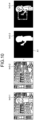
camera 10 is used, in some cases, the shelf appears in the background of the user and the same product as the product held by the user may also appear, which leads to reduction in determination accuracy on whether the user is holding the product. Thedetermination unit 157 may compare an image (background image) that is obtained before the user C appears and a current image to improve image recognition accuracy. -
FIG. 10 is a diagram for explaining another process performed by the determination unit. As illustrated inFIG. 10 , when extracting an input image Im5-1 (video information) from the video buffer 141 and performing image processing, thedetermination unit 157 generates a foreground mask Im5-3 by subtracting a background image Im5-2 that is prepared in advance from the input image Im5-1. Thedetermination unit 157 compares the input image Im5-1 and the foreground mask Im5-3, and generates an image Im5-4 in which an area other than an area of a mask A1 is extracted. The image Im5-4 does not include a background image, so that it is possible to improve accuracy in executing the detection process as described above with reference toFIG. 9 . - One example of the flow of the process performed by the
information processing apparatus 100 according to the present embodiment will be described below.FIG. 11 is a flowchart illustrating a pre-setting process performed by the information processing apparatus. As illustrated inFIG. 11 , the receivingunit 151 of theinformation processing apparatus 100 receives video information from thecamera 10, and stores the video information in the video buffer 141 (Step S101). - The
depth identification unit 152 of theinformation processing apparatus 100 inputs the video information into the first learning model, and generates the depth image information 142 (Step S102). Theposture estimation unit 153 of theinformation processing apparatus 100 inputs the video information into the second learning model, and generates the skeleton information (Step S103). - The movement
trajectory calculation unit 154 of theinformation processing apparatus 100 generates the information on the movement trajectory on the basis of the chronological skeleton information, and stores the information on the movement trajectory in the movement trajectory table 143 (Step S104). Theaisle estimation unit 155 of theinformation processing apparatus 100 estimates the aisle area and the aisle direction on the basis of the information on the movement trajectory stored in the movement trajectory table 143 (Step S105). - The detection
line setting unit 156 of theinformation processing apparatus 100 generates the in-store 3D model M1 on the basis of the depth image information 142, the aisle area, and the aisle direction (Step S106). -
FIG. 12 is a flowchart illustrating the detection process performed by the information processing apparatus. As illustrated inFIG. 12 , the receivingunit 151 of theinformation processing apparatus 100 receives video information from thecamera 10, and stores the video information in the video buffer 141 (Step S201). - The
posture estimation unit 153 of theinformation processing apparatus 100 inputs the video information into the second learning model, and generates the skeleton information (Step S202). The detectionline setting unit 156 of theinformation processing apparatus 100 calculates a position of a foot on the basis of the skeleton information (Step S203). The detectionline setting unit 156 sets the detection line on the basis of the in-store 3D model M1 and the position of the foot (Step S204). - The
determination unit 157 of theinformation processing apparatus 100 calculates a position of a hand on the basis of the skeleton information (Step S205). Thedetermination unit 157 calculates a distance between the position of the detection line and the position of the hand (Step S206). If the distance is smaller than a threshold (Yes at Step S207), thedetermination unit 157 determines that the user has extended the hand to a product on the shelf, and detects an action of taking out the product (Step S208). - In contrast, if the distance is not smaller than the threshold (No at Step S207), the
determination unit 157 terminates the process. - Effects achieved by the
information processing apparatus 100 according to the present embodiment will be described below. Theinformation processing apparatus 100 generates the in-store 3D model M1 on the basis of the depth image information 142 and the movement trajectory of the user, which are obtained from the video information of thecamera 10, sets a detection line of a shelf for each standing position of the user on a floor, and uses the detection line for detection. In this manner, by setting the detection line for each standing position of the user, it is possible to detect taking in and out a product with high accuracy as compared to a case in which the detection line is set in advance as in the conventional technology. - The
information processing apparatus 100 identifies a change of the position of the foot of the user on the basis of the pieces of chronological skeleton information on the user, and identifies, as an aisle area, a polygon in which the identified change of the position of the foot is included. With this configuration, it is possible to identify three-dimensional positions of the aisle area and the shelf in the in-store 3D model M1. - The
information processing apparatus 100 identifies a change of the position of the foot of the user on the basis of the pieces of chronological skeleton information on the user, and identifies the aisle direction on the basis of the displacement directional vector based on the identified position of the foot. By arranging a plane that crosses the identified aisle direction at a right angle in the in-store 3D model M1, it is possible to set the detection line with high accuracy. - The
information processing apparatus 100 sets the detection line for each standing position of the user, identifies a part corresponding to a hand of the user on the basis of the skeleton information on the user, and detects that the user has extended the hand to a product stored in the shelf, on the basis of a positional relationship between the detection line and the part of the hand. With this configuration, it is possible to detect the action of taking out the product from the user. - Furthermore, according to the
information processing apparatus 100, it is possible to set the detection line by setting the in-store 3D model M1 in advance and identifying only the position of the foot of the user, so that it is possible to reduce a processing load of theinformation processing apparatus 100. Moreover, it is possible to detect the action of taking out a product from the shelf by the user without using a high-definition camera. - One example of a hardware configuration of a computer that implements the same functions as those of the
information processing apparatus 100 of the embodiment as described above will be described below.FIG. 13 is a diagram illustrating an example of the hardware configuration of the computer that implements the same functions as those of the information processing apparatus of one embodiment. - As illustrated in
FIG. 13 , a computer 300 includes a CPU 301 that performs various kinds of arithmetic processing, an input device 302 that receives input of data from a user, and adisplay 303. Furthermore, the computer 300 includes acommunication apparatus 304 that transmits and receives data to and from an external apparatus or the like via a wired or wireless network, and aninterface apparatus 305. Moreover, the computer 300 includes a random access memory (RAM) 306 for temporarily storing various kinds of information, and a hard disk device 307. Furthermore, all of the devices 301 to 307 are connected to abus 308. - The hard disk device 307 includes a
reception program 307a, adepth identification program 307b, aposture estimation program 307c, a movementtrajectory calculation program 307d, and anaisle estimation program 307e. The hard disk device 307 further includes a detectionline setting program 307f and adetermination program 307g. Furthermore, the CPU 301 reads each of theprograms 307a to 307g and loads theprograms 307a to 307g onto the RAM 306. - The
reception program 307a functions as areception process 306a. Thedepth identification program 307b functions as adepth identification process 306b. Theposture estimation program 307c functions as aposture estimation process 306c. The movementtrajectory calculation program 307d functions as a movementtrajectory calculation process 306d. Theaisle estimation program 307e functions as anaisle estimation process 306e. The detectionline setting program 307f functions as a detectionline setting process 306f. Thedetermination program 307g functions as adetermination process 306g. - A process of the
reception process 306a corresponds to the process performed by the receivingunit 151. A process of thedepth identification process 306b corresponds to the process performed by thedepth identification unit 152. A process of theposture estimation process 306c corresponds to the process performed by theposture estimation unit 153. A process of the movementtrajectory calculation process 306d corresponds to the process performed by the movementtrajectory calculation unit 154. A process of theaisle estimation process 306e corresponds to the process performed by theaisle estimation unit 155. A process of the detectionline setting process 306f corresponds to the process performed by the detectionline setting unit 156. A process of thedetermination process 306g corresponds to the process performed by thedetermination unit 157. - Meanwhile, each of the
programs 307a to 307g need not always be stored in the hard disk device 307 from the beginning. For example, each of the programs may be stored in a "portable physical medium", such as a flexible disk (FD), a compact disk-ROM (CD-ROM), a digital versatile disk (DVD), a magneto optical disk, or an integrated circuit (IC) card, which is inserted into the computer 300. Further, the computer 300 may read and execute each of theprograms 307a to 307g. - It is possible to detect taking in and out a product.
Claims (12)
- A setting program that causes a computer to execute a process, the process comprising:acquiring a video from a camera that is set in a store that has a storage unit in which a product is stored;identifying a depth indicating a distance from the camera to each of constituent elements of the video acquired from the camera, by inputting the acquired video into a machine learning model;generating a three-dimensional in-store model that is configured with the identified depth indicating the distance from the camera to each of the constituent elements of the video;generating skeleton information on a person who moves inside the store from the video acquired from the camera;setting a range and a direction of an aisle in the store in the generated three-dimensional in-store model based on a change in the generated skeleton information; andsetting a detection line in the storage unit based on the range and the direction of the aisle in the store, the detection line for detecting that the person has extended a hand to a product.
- The setting program according to claim 1, wherein the setting the range and the direction of the aisle in the store includesidentifying a change of a position of a foot included in the skeleton information on the person; andsetting, as the range of the aisle, a polygon that includes a change of the identified position of the foot.
- The setting program according to claim 1 or 2, wherein the setting the range and the direction of the aisle in the store includesidentifying a change of a position of a foot included in the skeleton information on the person; andsetting the direction based on a displacement directional vector that is based on the change of the position of the foot.
- A detection program that causes a computer to execute a process, the process comprising:identifying a detection line for detecting that a person has extended a hand to a product, the detection line being included in setting information, the setting information being set in a storage unit, based on range and a direction of an aisle in a store, the range and the direction being included in a three-dimensional in-store model that is configured with a depth indicating a distance from a camera that is set in the store to each of constituent elements of a video from the camera;identifying a part corresponding to a hand of the person based on skeleton information on the person generated from a video in which an inside of the store is captured; anddetecting that the person has extended the hand to a product that is stored in the storage unit, based on a positional relationship between the identified part corresponding to the hand of the person and the detection line included in the setting information.
- A setting method comprising:acquiring a video from a camera that is set in a store that has a storage unit in which a product is stored;identifying a depth indicating a distance from the camera to each of constituent elements of the video acquired from the camera, by inputting the acquired video into a machine learning model;generating a three-dimensional in-store model that is configured with the identified depth indicating the distance from the camera to each of the constituent elements of the video;generating skeleton information on a person who moves inside the store from the video acquired from the camera;setting a range and a direction of an aisle in the store in the generated three-dimensional in-store model based on a change in the generated skeleton information; andsetting a detection line in the storage unit based on the range and the direction of the aisle in the store, the detection line for detecting that the person has extended a hand to a product.
- The setting method according to claim 5, wherein the setting the range and the direction of the aisle in the store includesidentifying a change of a position of a foot included in the skeleton information on the person; andsetting, as the range of the aisle, a polygon that includes a change of the identified position of the foot.
- The setting method according to claim 5 or 6, wherein setting the range and the direction of the aisle in the store includesidentifying a change of a position of a foot included in the skeleton information on the person; andsetting the direction based on a displacement directional vector that is based on the change of the position of the foot.
- A detection method comprising:identifying setting information, the setting information being information in which a detection line for detecting that a person has extended a hand to a product is set in a storage unit that is arranged in a store, in a three-dimensional in-store model that is configured with a depth indicating a distance from a camera that is set in the store to each of constituent elements of a video from the camera;identifying a part corresponding to a hand of the person based on skeleton information on the person generated from a video in which an inside of the store is captured; anddetecting that the person has extended the hand to a product that is stored in the storage unit, based on a positional relationship between the identified part corresponding to the hand of the person and the detection line included in the setting information.
- A setting apparatus comprising:a control unit (150) configured toacquire a video from a camera that is set in a store that has a storage unit in which a product is stored;identify a depth indicating a distance from the camera to each of constituent elements of the video acquired from the camera, by inputting the acquired video into a machine learning model;generate a three-dimensional in-store model that is configured with the identified depth indicating the distance from the camera to each of the constituent elements of the video;generate skeleton information on a person who moves inside the store from the video acquired from the camera;set a range and a direction of an aisle in the store in the generated three-dimensional in-store model based on a change in the generated skeleton information; andset a detection line in the storage unit based on the range and the direction of the aisle in the store, the detection line for detecting that the person has extended a hand to a product.
- The setting apparatus according to claim 9, wherein the control unit (150) is further configured toidentifying a change of a position of a foot included in the skeleton information on the person; andsetting, as the range of the aisle, a polygon that includes a change of the identified position of the foot.
- A setting apparatus according to claim 9 or 10, wherein the control unit (150) is further configured toidentifying a change of a position of a foot included in the skeleton information on the person; andsetting the direction based on a displacement directional vector that is based on the change of the position of the foot.
- A detection apparatus comprising:a control unit (150) configured to
identify a detection line for detecting that a person has extended a hand to a product, the detection line being included in setting information, the setting information being set in a storage unit, based on range and a direction of an aisle in a store, the range and the direction being included in a three-dimensional in-store model that is configured with a depth indicating a distance from a camera that is set in the store to each of constituent elements of a video from the camera;identify a part corresponding to a hand of the person based on skeleton information on the person generated from a video in which an inside of the store is captured; anddetect that the person has extended the hand to a product that is stored in the storage unit, based on a positional relationship between the identified part corresponding to the hand of the person and the detection line included in the setting information.
Applications Claiming Priority (1)
| Application Number | Priority Date | Filing Date | Title |
|---|---|---|---|
| JP2022023946A JP7794014B2 (en) | 2022-02-18 | 2022-02-18 | Setting program, setting method and setting device |
Publications (1)
| Publication Number | Publication Date |
|---|---|
| EP4231251A1 true EP4231251A1 (en) | 2023-08-23 |
Family
ID=84044046
Family Applications (1)
| Application Number | Title | Priority Date | Filing Date |
|---|---|---|---|
| EP22204087.5A Pending EP4231251A1 (en) | 2022-02-18 | 2022-10-27 | Setting program, detection program, setting method, detection method, setting apparatus, and detection appratus |
Country Status (3)
| Country | Link |
|---|---|
| US (1) | US12051246B2 (en) |
| EP (1) | EP4231251A1 (en) |
| JP (1) | JP7794014B2 (en) |
Families Citing this family (1)
| Publication number | Priority date | Publication date | Assignee | Title |
|---|---|---|---|---|
| US12198377B1 (en) * | 2023-07-11 | 2025-01-14 | Tomahawk Robotics, Inc. | Point of interest tracking and estimation |
Citations (4)
| Publication number | Priority date | Publication date | Assignee | Title |
|---|---|---|---|---|
| US10282852B1 (en) * | 2018-07-16 | 2019-05-07 | Accel Robotics Corporation | Autonomous store tracking system |
| CN109871804A (en) * | 2019-02-19 | 2019-06-11 | 上海宝尊电子商务有限公司 | A kind of method and system of shop stream of people discriminance analysis |
| US10373322B1 (en) * | 2018-07-16 | 2019-08-06 | Accel Robotics Corporation | Autonomous store system that analyzes camera images to track people and their interactions with items |
| JP2021107989A (en) | 2019-12-27 | 2021-07-29 | キヤノンマーケティングジャパン株式会社 | Information processing device, information processing method, and program |
Family Cites Families (6)
| Publication number | Priority date | Publication date | Assignee | Title |
|---|---|---|---|---|
| JP2012173903A (en) * | 2011-02-21 | 2012-09-10 | Jvc Kenwood Corp | Rack monitoring device |
| WO2017150590A1 (en) * | 2016-02-29 | 2017-09-08 | サインポスト株式会社 | Information processing system |
| US11003900B2 (en) * | 2018-02-20 | 2021-05-11 | Uplift Labs, Inc. | Identifying movements and generating prescriptive analytics using movement intelligence |
| JP6779410B2 (en) * | 2018-05-17 | 2020-11-04 | 三菱電機株式会社 | Video analyzer, video analysis method, and program |
| JP6597838B1 (en) * | 2018-06-01 | 2019-10-30 | 日本電気株式会社 | Flow line analysis apparatus, flow line analysis method, and flow line analysis system |
| US10535146B1 (en) * | 2018-07-16 | 2020-01-14 | Accel Robotics Corporation | Projected image item tracking system |
-
2022
- 2022-02-18 JP JP2022023946A patent/JP7794014B2/en active Active
- 2022-10-27 EP EP22204087.5A patent/EP4231251A1/en active Pending
- 2022-11-02 US US17/978,980 patent/US12051246B2/en active Active
Patent Citations (4)
| Publication number | Priority date | Publication date | Assignee | Title |
|---|---|---|---|---|
| US10282852B1 (en) * | 2018-07-16 | 2019-05-07 | Accel Robotics Corporation | Autonomous store tracking system |
| US10373322B1 (en) * | 2018-07-16 | 2019-08-06 | Accel Robotics Corporation | Autonomous store system that analyzes camera images to track people and their interactions with items |
| CN109871804A (en) * | 2019-02-19 | 2019-06-11 | 上海宝尊电子商务有限公司 | A kind of method and system of shop stream of people discriminance analysis |
| JP2021107989A (en) | 2019-12-27 | 2021-07-29 | キヤノンマーケティングジャパン株式会社 | Information processing device, information processing method, and program |
Also Published As
| Publication number | Publication date |
|---|---|
| JP2023120848A (en) | 2023-08-30 |
| US20230267744A1 (en) | 2023-08-24 |
| JP7794014B2 (en) | 2026-01-06 |
| US12051246B2 (en) | 2024-07-30 |
Similar Documents
| Publication | Publication Date | Title |
|---|---|---|
| US9877012B2 (en) | Image processing apparatus for estimating three-dimensional position of object and method therefor | |
| JP7332183B2 (en) | Information processing device, control method, and program | |
| US9367732B2 (en) | Information processing device, information processing method, and recording medium | |
| US20150253864A1 (en) | Image Processor Comprising Gesture Recognition System with Finger Detection and Tracking Functionality | |
| JP5251987B2 (en) | Person determination device, method and program | |
| EP3531341B1 (en) | Method and apparatus for recognising an action of a hand | |
| KR20110003146A (en) | Gesture recognition device, robot system having same and gesture recognition method using same | |
| JP7162079B2 (en) | A recording medium for recording a method, system and computer program for remotely controlling a display device via head gestures | |
| JP7188240B2 (en) | Human detection device and human detection method | |
| US10496874B2 (en) | Facial detection device, facial detection system provided with same, and facial detection method | |
| JP6728865B2 (en) | Hand lift detection device and hand lift detection program | |
| US20220395193A1 (en) | Height estimation apparatus, height estimation method, and non-transitory computer readable medium storing program | |
| EP4231251A1 (en) | Setting program, detection program, setting method, detection method, setting apparatus, and detection appratus | |
| JP6290020B2 (en) | Image processing apparatus, image processing method, and program | |
| JP6331270B2 (en) | Information processing system, information processing method, and program | |
| JP6606340B2 (en) | Image detection apparatus, image detection method, and program | |
| JP2004303014A (en) | Gesture recognition device, gesture recognition method, and gesture recognition program | |
| KR102576795B1 (en) | Method for obtaining frontal image based on pose estimation and apparatus using the same | |
| US20240282147A1 (en) | Action recognition method, action recognition device, and non-transitory computer readable recording medium | |
| CN110377187A (en) | Estimation is blocked method and apparatus, gesture recognition system and the storage medium of finger tip | |
| EP4485369A1 (en) | Information processing program, information processing method, and information processing apparatus | |
| JP2021144359A (en) | Learning apparatus, estimation apparatus, learning method, and program | |
| JP2012221164A (en) | Motion vector detection device, motion vector detection method and motion vector detection program | |
| US11881045B2 (en) | Region extraction device, region extraction method, and region extraction program | |
| KR101653235B1 (en) | Apparatus and method for econgnizing gesture |
Legal Events
| Date | Code | Title | Description |
|---|---|---|---|
| PUAI | Public reference made under article 153(3) epc to a published international application that has entered the european phase |
Free format text: ORIGINAL CODE: 0009012 |
|
| STAA | Information on the status of an ep patent application or granted ep patent |
Free format text: STATUS: THE APPLICATION HAS BEEN PUBLISHED |
|
| AK | Designated contracting states |
Kind code of ref document: A1 Designated state(s): AL AT BE BG CH CY CZ DE DK EE ES FI FR GB GR HR HU IE IS IT LI LT LU LV MC ME MK MT NL NO PL PT RO RS SE SI SK SM TR |
|
| STAA | Information on the status of an ep patent application or granted ep patent |
Free format text: STATUS: REQUEST FOR EXAMINATION WAS MADE |
|
| 17P | Request for examination filed |
Effective date: 20231208 |
|
| RBV | Designated contracting states (corrected) |
Designated state(s): AL AT BE BG CH CY CZ DE DK EE ES FI FR GB GR HR HU IE IS IT LI LT LU LV MC ME MK MT NL NO PL PT RO RS SE SI SK SM TR |
|
| STAA | Information on the status of an ep patent application or granted ep patent |
Free format text: STATUS: EXAMINATION IS IN PROGRESS |
|
| 17Q | First examination report despatched |
Effective date: 20240403 |
|
| GRAP | Despatch of communication of intention to grant a patent |
Free format text: ORIGINAL CODE: EPIDOSNIGR1 |
|
| STAA | Information on the status of an ep patent application or granted ep patent |
Free format text: STATUS: GRANT OF PATENT IS INTENDED |
|
| INTG | Intention to grant announced |
Effective date: 20260113 |