EP4231117A1 - Casing with replacement structure and electronic device - Google Patents
Casing with replacement structure and electronic device Download PDFInfo
- Publication number
- EP4231117A1 EP4231117A1 EP22209286.8A EP22209286A EP4231117A1 EP 4231117 A1 EP4231117 A1 EP 4231117A1 EP 22209286 A EP22209286 A EP 22209286A EP 4231117 A1 EP4231117 A1 EP 4231117A1
- Authority
- EP
- European Patent Office
- Prior art keywords
- casing
- assembly
- frame
- replacement
- expansion device
- Prior art date
- Legal status (The legal status is an assumption and is not a legal conclusion. Google has not performed a legal analysis and makes no representation as to the accuracy of the status listed.)
- Granted
Links
Images



Classifications
-
- H—ELECTRICITY
- H05—ELECTRIC TECHNIQUES NOT OTHERWISE PROVIDED FOR
- H05K—PRINTED CIRCUITS; CASINGS OR CONSTRUCTIONAL DETAILS OF ELECTRIC APPARATUS; MANUFACTURE OF ASSEMBLAGES OF ELECTRICAL COMPONENTS
- H05K5/00—Casings, cabinets or drawers for electric apparatus
- H05K5/02—Details
- H05K5/0217—Mechanical details of casings
- H05K5/0221—Locks; Latches
-
- G—PHYSICS
- G06—COMPUTING OR CALCULATING; COUNTING
- G06F—ELECTRIC DIGITAL DATA PROCESSING
- G06F1/00—Details not covered by groups G06F3/00 - G06F13/00 and G06F21/00
- G06F1/16—Constructional details or arrangements
- G06F1/1613—Constructional details or arrangements for portable computers
- G06F1/1615—Constructional details or arrangements for portable computers with several enclosures having relative motions, each enclosure supporting at least one I/O or computing function
- G06F1/1616—Constructional details or arrangements for portable computers with several enclosures having relative motions, each enclosure supporting at least one I/O or computing function with folding flat displays, e.g. laptop computers or notebooks having a clamshell configuration, with body parts pivoting to an open position around an axis parallel to the plane they define in closed position
-
- G—PHYSICS
- G06—COMPUTING OR CALCULATING; COUNTING
- G06F—ELECTRIC DIGITAL DATA PROCESSING
- G06F1/00—Details not covered by groups G06F3/00 - G06F13/00 and G06F21/00
- G06F1/16—Constructional details or arrangements
- G06F1/1613—Constructional details or arrangements for portable computers
- G06F1/1632—External expansion units, e.g. docking stations
-
- G—PHYSICS
- G06—COMPUTING OR CALCULATING; COUNTING
- G06F—ELECTRIC DIGITAL DATA PROCESSING
- G06F1/00—Details not covered by groups G06F3/00 - G06F13/00 and G06F21/00
- G06F1/16—Constructional details or arrangements
- G06F1/1613—Constructional details or arrangements for portable computers
- G06F1/1633—Constructional details or arrangements of portable computers not specific to the type of enclosures covered by groups G06F1/1615 - G06F1/1626
- G06F1/1635—Details related to the integration of battery packs and other power supplies such as fuel cells or integrated AC adapter
-
- G—PHYSICS
- G06—COMPUTING OR CALCULATING; COUNTING
- G06F—ELECTRIC DIGITAL DATA PROCESSING
- G06F1/00—Details not covered by groups G06F3/00 - G06F13/00 and G06F21/00
- G06F1/16—Constructional details or arrangements
- G06F1/1613—Constructional details or arrangements for portable computers
- G06F1/1633—Constructional details or arrangements of portable computers not specific to the type of enclosures covered by groups G06F1/1615 - G06F1/1626
- G06F1/1656—Details related to functional adaptations of the enclosure, e.g. to provide protection against EMI, shock, water, or to host detachable peripherals like a mouse or removable expansions units like PCMCIA cards, or to provide access to internal components for maintenance or to removable storage supports like CDs or DVDs, or to mechanically mount accessories
-
- G—PHYSICS
- G06—COMPUTING OR CALCULATING; COUNTING
- G06F—ELECTRIC DIGITAL DATA PROCESSING
- G06F1/00—Details not covered by groups G06F3/00 - G06F13/00 and G06F21/00
- G06F1/16—Constructional details or arrangements
- G06F1/18—Packaging or power distribution
- G06F1/181—Enclosures
-
- G—PHYSICS
- G06—COMPUTING OR CALCULATING; COUNTING
- G06F—ELECTRIC DIGITAL DATA PROCESSING
- G06F1/00—Details not covered by groups G06F3/00 - G06F13/00 and G06F21/00
- G06F1/16—Constructional details or arrangements
- G06F1/18—Packaging or power distribution
- G06F1/183—Internal mounting support structures, e.g. for supporting printed circuit boards
-
- H—ELECTRICITY
- H05—ELECTRIC TECHNIQUES NOT OTHERWISE PROVIDED FOR
- H05K—PRINTED CIRCUITS; CASINGS OR CONSTRUCTIONAL DETAILS OF ELECTRIC APPARATUS; MANUFACTURE OF ASSEMBLAGES OF ELECTRICAL COMPONENTS
- H05K5/00—Casings, cabinets or drawers for electric apparatus
- H05K5/02—Details
- H05K5/03—Covers
Definitions
- the present application relates to a casing, and more particular to a casing with a replacement structure and an electronic device having the casing with a replacement structure.
- a conventional electronic device is usually provided with an optical disk drive.
- the position occupied by the optical disk drive cannot be used by a function expansion component or be replaced by other function components, causing limited functions of the electronic device and failing to provide customers with more diversified options.
- a casing with a replacement structure provided according to an embodiment includes the casing and a replacement assembly.
- the casing includes a casing body and an assembly space.
- the assembly space is provided in a recessed manner at the casing body and is located at a vertical intersection of two side edges of the casing body.
- the replacement assembly includes a frame, which is installed in the assembly space and encloses with the casing body to form an accommodating space.
- the frame is installed in the assembly space, and the frame at least substitutes for the two vertically intersecting side edges of the casing.
- the replacement assembly includes an expansion device, which is installed in the accommodating space.
- the frame has an opening portion, which is provided to face an outer side of the frame.
- the frame includes a first hole
- the expansion device includes a bracket and an expansion member.
- the expansion member is installed on the bracket.
- the bracket includes a second hole, and first hole corresponds to the second hole.
- the frame and the bracket are mutually fixed by a fixing member.
- the bracket further includes a lever.
- a cover plate is included.
- the cover plate is installed on the replacement assembly and covers the accommodating space.
- the casing body has a connection portion
- the frame has an opening portion, wherein the opening portion is provided to face the connection portion.
- the expansion device is electrically connected to the connection portion via the opening portion.
- a waterproof member protruding from the opening portion is included.
- the frame includes a latch assembly.
- the latch assembly has a toggle lever and an engagement portion.
- the toggle lever is connected to the engagement portion so as to move the engagement portion between a lock position and a release position by the toggle lever.
- An electronic device further provided according to another embodiment includes a casing and a replacement assembly.
- the casing includes a casing body and an assembly space.
- the assembly space is provided in a recessed manner at the casing body and is located at a vertical intersection of two side edges of the casing body.
- the replacement assembly includes a frame, which is installed in the assembly space and encloses with the casing body to form an accommodating space.
- An electronic device further provided according to another embodiment includes a casing and a replacement assembly.
- the casing includes a casing body and an assembly space.
- the assembly space is provided in a recessed manner on a corner of the casing body.
- the replacement assembly includes a frame and an expansion device.
- the frame is installed in the assembly space and encloses with the casing body to form an accommodating space.
- the expansion device is installed in the accommodating space.
- a casing with a replacement structure and an electronic device are provided according to the embodiments above.
- the assembly space for installing the replacement assembly at a vertical intersection of two side edges of the casing body, occupying the space of the electronic device is avoided.
- the frame of the replacement assembly for part of the casing body, the material used by the casing body can be reduced, and the casing body is allowed to be more intact as having a reduced number of holes.
- the replacement assembly can be more easily aligned and installed during the assembly process.
- the replacement assembly is selectively removable from the assembly space, further achieving an effect of quick replacement.
- FIG. 1 shows a perspective schematic diagram of a casing with a replacement structure according to a first embodiment.
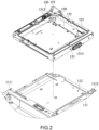
- FIG. 2 shows an exploded partial perspective diagram of a casing with a replacement structure according to the first embodiment.
- a casing 100 with a replacement structure of this embodiment includes a casing 110 and a replacement assembly 130.
- the casing 100 with a replacement structure is applied to an electronic device, which is, for example, a laptop computer, a keyboard dock or an office dock.
- the casing 100 with a replacement structure serves as a casing of a laptop computer, and is selectively removable from an electronic device through the replacement assembly 130, so as to achieve effects of quickly replacement of function components and adaptability to different function components according to requirements.
- the casing 110 includes a casing body 111 and an assembly space 112.
- the assembly space 112 is provided in a recessed manner at the casing body 111 and is located at a vertical intersection of two side edges 1111 and 1112 of the casing body 111.
- the assembly space 112 is located at the intersection of the two side edges 1111 and 1112 of the casing body 111, that is, a corner of the casing 110, so that configurations of other peripheral components are less likely affected because the assembly space 112 is located on the corner.
- the replacement assembly 130 includes a frame 131, which is installed in the assembly space 112 and encloses with the casing body 111 to form an accommodating space 132.
- the replacement assembly 130 can be selectively removed from or installed to the casing 110 by means of, for example, screw locking.
- the frame 131 of the replacement assembly 130 is installed in the assembly space 112 formed in a recessed manner from the casing body 111 so as to replace a recessed region of the casing body 111, and encloses with the casing body 111 to form the accommodating space 132.
- the accommodating space 132 is for installing an expansion device 150.
- the expansion device 150 is, for example, an optical drive assembly, a hard drive assembly or a battery assembly. The relation between the expansion device 150 and the replacement assembly 130 is to be described later.
- the assembly space 112 for installing the replacement assembly 130 is provided at the vertical intersection between the two side edges 1111 and 1112 of the casing body 111, so as to avoid occupying the space of the other peripheral components.
- the frame 131 of the replacement assembly130 for part of the casing body 111, the material used by the casing body 111 can be reduced, and the casing body 1111 is allowed to be more intact as having a reduced number of holes.
- the replacement assembly 130 can be more easily aligned and installed during the assembly process.
- the replacement assembly 130 is selectively removable from the assembly space 112, further achieving an effect of quick replacement of function components.
- customers are provided with more diversified function options.
- the frame 131 is installed in the assembly space 112, and the frame 131 at least substitutes for the two vertically intersecting side edges 1111 and 1112 of the casing 110.
- the frame 131 at least substitutes for the two vertically intersecting side edges 1111 and 1112 of the casing 110.
- FIG. 1 and FIG. 2 due to the assembly space 112 formed in a recessed manner, at least a portion of each of the two side edges 1111 and 1112 of the casing 110 is also recessed.
- the frame 131 while substituting the frame 131 for the recessed region of the casing body 111, it at the same time substitutes for the two vertically intersecting side edges 1111 and 1112 of the casing 110.
- FIG. 3 shows an operation schematic diagram of a replacement assembly according to the first embodiment.
- the replacement assembly 130 includes an expansion device 150, which is installed in the accommodating space 132.
- the expansion device 150 is, for example, an optical drive assembly.
- the frame 131 has an opening portion 1311, which is provided to face an outer side of the frame 131.
- the expansion device 150 can selectively enter or exit the accommodating space from the opening portion 1311.
- the opening portion 1311 is, for example but not limited to, located the side edge 1111, or may be located at the side edge 1112.
- the frame 131 includes a block plate 1314.
- the block plate 1314 corresponds to the opening portion 1311, is pivotally connected at the side edge 1111, and selectively opens or closes the opening portion 1311.
- the frame 131 includes a first hole 1312
- the expansion device 150 includes a bracket 151 and an expansion member 152.
- the expansion member 152 is installed on the bracket 151
- the bracket 151 includes a second hole 1511.
- the fixing member 153 is, for example, a quick removal screw and is an independent element, which selectively passes through or is removed from the first hole 1312 and the second hole 1511, so as to achieve the function of releasing the fixing relation between the expansion device 150 and the frame 131.
- the expansion device 150 when the expansion device 150 is located in the accommodating space 132, the first hole 1312 on the frame 131 corresponds to the second hole 1511 on the bracket 151, and the expansion device 150 is fixed on the frame 131 by passing the fixing member 153 through the first hole 1312 and the second hole 1511.
- the fixing member 132 is removed from the first hole 1312 and the second hole 1511, such that the fixing relation between the expansion device 150 and the frame 131 is released, thus allowing the expansion device 150 to be taken out of the opening portion 1311.
- the fixing member 153 may also be an element on the frame 131.
- the fixing member 153 is provided on the first hole 1312, for example, slidably arranged at the first hole 1312 or screw locked at the first hole 1312, allowing the quick removal screw to move relative to the second hole 1511.
- the fixing member 132 is moved back to the first hole 1511, such that the fixing relation between the expansion device 150 and the frame 131 is released, thus allowing the expansion device 150 to be taken out of the opening portion 1311.
- the bracket 151 further includes a lever 1512.
- the lever 1512 is, for example, provided in an extendable manner at the bracket 151. To remove the expansion device 150 from the opening 1311, the lever 1512 is extended to protrude from the opening portion 1311, allowing a user to hold the lever 1512 and thus more conveniently take out the expansion device 150 from the opening portion 1311. Once the expansion device 150 is taken out, the lever 1512 can be retracted for storage. Moreover, the lever 1512 may also be pivotally connected on the bracket 151. To take out the expansion device 150 from the opening portion 1311, the lever 1512 is rotated to face the opening portion 1311, better allowing pulling by a user. Once the expansion device 150 is taken out, the lever 1512 can be rotated for storage.
- FIG. 4 shows a section schematic diagram of assembly of an expansion device according to the first embodiment.
- the casing body 111 includes a connection portion 113
- the frame 131 includes an opening portion 1313
- the opening portion 1313 is provided to correspond to the connection portion 113.
- the expansion device 150 is electrically connected to the connection portion 113 through the opening portion 1313.
- the connection portion 113 is, for example, a connection terminal, and can pass through the opening portion 1313 so as to be electrically connected to a female end of the expansion device 150.
- the expansion device 150 may also have a male connection terminal, the connection portion 113 is a female end, and the connection terminal of the expansion device 150 can pass through the opening portion 1313 so as to be electrically connected to the connection portion 113.
- the bracket 131 includes a waterproof member 133, which protrudes from the opening portion 1313.
- the waterproof member 133 is, for example but not limited to, a hollow protruding member formed on the frame 133 and protruding toward the connection portion 113, or may be an independent element.
- the casing body 111 further includes a connection hole portion 114, the connection portion 113 passes through the connection hole portion 114, and the waterproof member 133 passes through the connection hole portion 114 and envelops the connection portion 113.
- a liquid can be prevented from invading the interior of the casing 110 from between the frame 131 and the casing body 111, and the connection between the expansion device 150 and the casing 110 can also be protected.
- the casing 100 with a replacement structure includes a cover plate 170, which is installed on the replacement assembly 130 and covers the accommodating space 132.
- the replacement component 130 is protected in the casing 110, and is prevented from external impacts and hence from damage.
- the structure of the cover plate 170 is omitted from the remaining drawings.
- FIG. 5 shows a perspective schematic diagram of a replacement assembly according to a second embodiment. Details of structures of the second embodiment the same as those of the first embodiment are omitted herein.
- an expansion device 250 is a hard drive assembly. Similar to the assembly method of the first embodiment, to remove an expansion device 250 from the accommodating space 132, a fixing member 253 is removed from the first hole 1312 and a second hole 2511, such that the fixing relation between the expansion device 250 and the frame 131 is released, thus allowing the expansion device 250 to be taken out of the opening portion 1311.
- FIG. 6 shows an exploded partial perspective diagram of a replacement assembly according to a third embodiment.
- FIG. 7 shows a schematic diagram of FIG. 6 from another angle. Details of structures of the third embodiment the same as those of the first embodiment are omitted herein.
- an expansion device 350 is a battery assembly.
- a replacement assembly 330 includes a frame 331, which is installed in the assembly space 112 and encloses with the casing body 111 to form an accommodating space 332.
- a frame 331 is a hollow support.
- the hollow part is an accommodating space 332.
- the expansion device 350 can be selectively removed from or installed in the accommodating space 332.
- the frame 331 includes a latch assembly 334, which has a toggle lever 3341 and an engagement portion 3342.
- the toggle lever 3341 is connected to the engagement portion 3342 so as to move the engagement portion 3342 between a lock position and a release position by the toggle lever 3341.
- the toggle 3341 is toggled to engage and fix the expansion device 350 with the engagement portion 3342.
- the toggle 3341 is toggled to release the engagement of the expansion device 350 from the engagement portion 3342.
- FIG. 8 shows a section schematic diagram of an expansion device according to the third embodiment.
- the casing body 111 has a connection portion 113
- the frame 331 has an opening portion 3313, wherein the opening portion 3313 is provided to face the connection portion 113.
- the expansion device 350 is electrically connected to the connection portion 113 via the opening portion 3313.
- the connection portion 113 is, for example, a connection terminal, and can pass through the opening portion 3313 so as to be electrically connected to a female end of the expansion device 350.
- the expansion device 350 may also have a male connection terminal, the connection portion 113 is a female end, and the connection terminal of the expansion device 350 can pass through the opening portion 3313 so as to be electrically connected to the connection portion 113.
- the frame 331 includes a waterproof member 333, which protrudes from the opening portion 3313.
- the waterproof member 333 is, for example, a hollow protruding member formed on the frame 133 and protruding toward the connection portion 113.
- the casing body 111 further includes a connection hole portion 114, the connection portion 113 passes through the connection hole portion 114, and the waterproof member 333 passes through the connection hole portion 114 and envelops the connection portion 113.
- the expansion device 350 further includes a connection member 353, which protrudes from the expansion device 350 so as to pass through the opening portion 3313 and to be electrically connected to the connection portion 113.
- a casing with a replacement structure and an electronic device are provided according to the embodiments above.
- the assembly space for installing the replacement assembly at a vertical intersection of two side edges of the casing body occupying the space of other peripheral components is avoided.
- the frame of the replacement assembly for part of the casing body, the material used by the casing body can be reduced, and the casing body is allowed to be more intact as having a reduced number of holes.
- the replacement assembly can be more easily aligned and installed during the assembly process.
- the replacement assembly is selectively removable from the assembly space, further achieving an effect of quick replacement; for example, an optical drive assembly serving as the expansion device can be replaced by a hard drive assembly, or be replaced by a battery assembly.
- an optical drive assembly serving as the expansion device can be replaced by a hard drive assembly, or be replaced by a battery assembly.
Landscapes
- Engineering & Computer Science (AREA)
- Theoretical Computer Science (AREA)
- Computer Hardware Design (AREA)
- Physics & Mathematics (AREA)
- General Engineering & Computer Science (AREA)
- Human Computer Interaction (AREA)
- General Physics & Mathematics (AREA)
- Power Engineering (AREA)
- Microelectronics & Electronic Packaging (AREA)
- Mathematical Physics (AREA)
- Casings For Electric Apparatus (AREA)
- Electrophonic Musical Instruments (AREA)
- Structure Of Telephone Exchanges (AREA)
Abstract
Description
- The present application relates to a casing, and more particular to a casing with a replacement structure and an electronic device having the casing with a replacement structure.
- A conventional electronic device is usually provided with an optical disk drive. However, the position occupied by the optical disk drive cannot be used by a function expansion component or be replaced by other function components, causing limited functions of the electronic device and failing to provide customers with more diversified options.
- In view of the above, a casing with a replacement structure provided according to an embodiment includes the casing and a replacement assembly. The casing includes a casing body and an assembly space. The assembly space is provided in a recessed manner at the casing body and is located at a vertical intersection of two side edges of the casing body. The replacement assembly includes a frame, which is installed in the assembly space and encloses with the casing body to form an accommodating space.
- In some embodiments, the frame is installed in the assembly space, and the frame at least substitutes for the two vertically intersecting side edges of the casing.
- In some embodiments, the replacement assembly includes an expansion device, which is installed in the accommodating space.
- In some embodiments, the frame has an opening portion, which is provided to face an outer side of the frame.
- In some embodiments, the frame includes a first hole, and the expansion device includes a bracket and an expansion member. The expansion member is installed on the bracket. The bracket includes a second hole, and first hole corresponds to the second hole. The frame and the bracket are mutually fixed by a fixing member.
- In some embodiments, the bracket further includes a lever.
- In some embodiments, a cover plate is included. The cover plate is installed on the replacement assembly and covers the accommodating space.
- In some embodiments, the casing body has a connection portion, and the frame has an opening portion, wherein the opening portion is provided to face the connection portion. The expansion device is electrically connected to the connection portion via the opening portion.
- In some embodiments, a waterproof member protruding from the opening portion is included.
- In some embodiments, the frame includes a latch assembly. The latch assembly has a toggle lever and an engagement portion. The toggle lever is connected to the engagement portion so as to move the engagement portion between a lock position and a release position by the toggle lever.
- An electronic device further provided according to another embodiment includes a casing and a replacement assembly. The casing includes a casing body and an assembly space. The assembly space is provided in a recessed manner at the casing body and is located at a vertical intersection of two side edges of the casing body. The replacement assembly includes a frame, which is installed in the assembly space and encloses with the casing body to form an accommodating space.
- An electronic device further provided according to another embodiment includes a casing and a replacement assembly. The casing includes a casing body and an assembly space. The assembly space is provided in a recessed manner on a corner of the casing body. The replacement assembly includes a frame and an expansion device. The frame is installed in the assembly space and encloses with the casing body to form an accommodating space. The expansion device is installed in the accommodating space.
- In conclusion, a casing with a replacement structure and an electronic device are provided according to the embodiments above. By providing the assembly space for installing the replacement assembly at a vertical intersection of two side edges of the casing body, occupying the space of the electronic device is avoided. Moreover, by substituting the frame of the replacement assembly for part of the casing body, the material used by the casing body can be reduced, and the casing body is allowed to be more intact as having a reduced number of holes. In addition, because the assembly space is completely exposed and visible, the replacement assembly can be more easily aligned and installed during the assembly process. Moreover, the replacement assembly is selectively removable from the assembly space, further achieving an effect of quick replacement.
-
-
FIG. 1 is a perspective schematic diagram of a casing with a replacement structure according to a first embodiment; -
FIG. 2 is an exploded partial perspective diagram of a casing with a replacement structure according to the first embodiment; -
FIG. 3 is an operation schematic diagram of a replacement assembly according to the first embodiment; -
FIG. 4 is a section schematic diagram of assembly of an expansion device according to the first embodiment; -
FIG. 5 is a perspective schematic diagram of a replacement assembly according to a second embodiment; -
FIG. 6 is an exploded partial perspective diagram of a replacement assembly according to a third embodiment; -
FIG. 7 is a schematic diagram ofFIG. 6 from another angle; and -
FIG. 8 is a section schematic diagram of an expansion device according to the third embodiment. - Refer to
FIG. 1 to FIG. 2 .FIG. 1 shows a perspective schematic diagram of a casing with a replacement structure according to a first embodiment.FIG. 2 shows an exploded partial perspective diagram of a casing with a replacement structure according to the first embodiment. Acasing 100 with a replacement structure of this embodiment includes acasing 110 and areplacement assembly 130. Thecasing 100 with a replacement structure is applied to an electronic device, which is, for example, a laptop computer, a keyboard dock or an office dock. For example, thecasing 100 with a replacement structure serves as a casing of a laptop computer, and is selectively removable from an electronic device through thereplacement assembly 130, so as to achieve effects of quickly replacement of function components and adaptability to different function components according to requirements. - The
casing 110 includes acasing body 111 and anassembly space 112. Theassembly space 112 is provided in a recessed manner at thecasing body 111 and is located at a vertical intersection of twoside edges casing body 111. In the first embodiment, theassembly space 112 is located at the intersection of the twoside edges casing body 111, that is, a corner of thecasing 110, so that configurations of other peripheral components are less likely affected because theassembly space 112 is located on the corner. As shown inFIG. 1 , there is sufficient space of the use of other peripheral components in each of the directions of theside edges - As shown in
FIG. 2 , thereplacement assembly 130 includes aframe 131, which is installed in theassembly space 112 and encloses with thecasing body 111 to form anaccommodating space 132. In the first embodiment, thereplacement assembly 130 can be selectively removed from or installed to thecasing 110 by means of, for example, screw locking. Moreover, theframe 131 of thereplacement assembly 130 is installed in theassembly space 112 formed in a recessed manner from thecasing body 111 so as to replace a recessed region of thecasing body 111, and encloses with thecasing body 111 to form theaccommodating space 132. In the first embodiment, theaccommodating space 132 is for installing anexpansion device 150. Theexpansion device 150 is, for example, an optical drive assembly, a hard drive assembly or a battery assembly. The relation between theexpansion device 150 and thereplacement assembly 130 is to be described later. - Specifically, in the
casing 100 with a replacement structure, theassembly space 112 for installing thereplacement assembly 130 is provided at the vertical intersection between the twoside edges casing body 111, so as to avoid occupying the space of the other peripheral components. Moreover, by substituting theframe 131 of the replacement assembly130 for part of thecasing body 111, the material used by thecasing body 111 can be reduced, and thecasing body 1111 is allowed to be more intact as having a reduced number of holes. In addition, because theassembly space 112 is completely exposed and visible, thereplacement assembly 130 can be more easily aligned and installed during the assembly process. Moreover, thereplacement assembly 130 is selectively removable from theassembly space 112, further achieving an effect of quick replacement of function components. Thus, customers are provided with more diversified function options. - In the first embodiment, the
frame 131 is installed in theassembly space 112, and theframe 131 at least substitutes for the two vertically intersectingside edges casing 110. As shown inFIG. 1 andFIG. 2 , due to theassembly space 112 formed in a recessed manner, at least a portion of each of the twoside edges casing 110 is also recessed. Thus, while substituting theframe 131 for the recessed region of thecasing body 111, it at the same time substitutes for the two vertically intersectingside edges casing 110. - Refer to
FIG. 3 as well asFIG. 2 .FIG. 3 shows an operation schematic diagram of a replacement assembly according to the first embodiment. In the first embodiment, thereplacement assembly 130 includes anexpansion device 150, which is installed in theaccommodating space 132. In a first embodiment, theexpansion device 150 is, for example, an optical drive assembly. In the first embodiment, theframe 131 has anopening portion 1311, which is provided to face an outer side of theframe 131. As shown inFIG. 3 , theexpansion device 150 can selectively enter or exit the accommodating space from theopening portion 1311. Moreover, theopening portion 1311 is, for example but not limited to, located theside edge 1111, or may be located at theside edge 1112. In the first embodiment, as shown inFIG. 3 , theframe 131 includes ablock plate 1314. Theblock plate 1314 corresponds to theopening portion 1311, is pivotally connected at theside edge 1111, and selectively opens or closes theopening portion 1311. - In this first embodiment, the
frame 131 includes afirst hole 1312, and theexpansion device 150 includes abracket 151 and anexpansion member 152. Theexpansion member 152 is installed on thebracket 151, and thebracket 151 includes asecond hole 1511. When theexpansion device 150 is installed at theframe 131, thefirst hole 1312 corresponds to thesecond hole 1511, and theframe 131 and thebracket 151 are mutually fixed by a fixingmember 153. As shown inFIG. 2 andFIG. 3 , the fixingmember 153 is, for example, a quick removal screw and is an independent element, which selectively passes through or is removed from thefirst hole 1312 and thesecond hole 1511, so as to achieve the function of releasing the fixing relation between theexpansion device 150 and theframe 131. As shown inFIG. 2 , when theexpansion device 150 is located in theaccommodating space 132, thefirst hole 1312 on theframe 131 corresponds to thesecond hole 1511 on thebracket 151, and theexpansion device 150 is fixed on theframe 131 by passing the fixingmember 153 through thefirst hole 1312 and thesecond hole 1511. As shown inFIG. 3 , to remove theexpansion device 150 from theaccommodating space 132, the fixingmember 132 is removed from thefirst hole 1312 and thesecond hole 1511, such that the fixing relation between theexpansion device 150 and theframe 131 is released, thus allowing theexpansion device 150 to be taken out of theopening portion 1311. Moreover, the fixingmember 153 may also be an element on theframe 131. For example, the fixingmember 153 is provided on thefirst hole 1312, for example, slidably arranged at thefirst hole 1312 or screw locked at thefirst hole 1312, allowing the quick removal screw to move relative to thesecond hole 1511. To remove theexpansion device 150 from theaccommodating space 132, the fixingmember 132 is moved back to thefirst hole 1511, such that the fixing relation between theexpansion device 150 and theframe 131 is released, thus allowing theexpansion device 150 to be taken out of theopening portion 1311. - In the first embodiment, as shown in
FIG. 2 andFIG. 3 , thebracket 151 further includes alever 1512. In the first embodiment, thelever 1512 is, for example, provided in an extendable manner at thebracket 151. To remove theexpansion device 150 from theopening 1311, thelever 1512 is extended to protrude from theopening portion 1311, allowing a user to hold thelever 1512 and thus more conveniently take out theexpansion device 150 from theopening portion 1311. Once theexpansion device 150 is taken out, thelever 1512 can be retracted for storage. Moreover, thelever 1512 may also be pivotally connected on thebracket 151. To take out theexpansion device 150 from theopening portion 1311, thelever 1512 is rotated to face theopening portion 1311, better allowing pulling by a user. Once theexpansion device 150 is taken out, thelever 1512 can be rotated for storage. - Refer to
FIG. 4. FIG. 4 shows a section schematic diagram of assembly of an expansion device according to the first embodiment. In the first embodiment, thecasing body 111 includes aconnection portion 113, theframe 131 includes anopening portion 1313, and theopening portion 1313 is provided to correspond to theconnection portion 113. Theexpansion device 150 is electrically connected to theconnection portion 113 through theopening portion 1313. As shown inFIG. 4 , theconnection portion 113 is, for example, a connection terminal, and can pass through theopening portion 1313 so as to be electrically connected to a female end of theexpansion device 150. Moreover, theexpansion device 150 may also have a male connection terminal, theconnection portion 113 is a female end, and the connection terminal of theexpansion device 150 can pass through theopening portion 1313 so as to be electrically connected to theconnection portion 113. - In the first embodiment, as shown in
FIG. 2 andFIG. 4 , thebracket 131 includes awaterproof member 133, which protrudes from theopening portion 1313. Thewaterproof member 133 is, for example but not limited to, a hollow protruding member formed on theframe 133 and protruding toward theconnection portion 113, or may be an independent element. In the first embodiment, thecasing body 111 further includes aconnection hole portion 114, theconnection portion 113 passes through theconnection hole portion 114, and thewaterproof member 133 passes through theconnection hole portion 114 and envelops theconnection portion 113. Thus, a liquid can be prevented from invading the interior of thecasing 110 from between theframe 131 and thecasing body 111, and the connection between theexpansion device 150 and thecasing 110 can also be protected. - In the first embodiment, as shown in
FIG. 1 , thecasing 100 with a replacement structure includes acover plate 170, which is installed on thereplacement assembly 130 and covers theaccommodating space 132. Thus, thereplacement component 130 is protected in thecasing 110, and is prevented from external impacts and hence from damage. For better illustration purpose, apart fromFIG. 1 , the structure of thecover plate 170 is omitted from the remaining drawings. - Refer to
FIG. 5. FIG. 5 shows a perspective schematic diagram of a replacement assembly according to a second embodiment. Details of structures of the second embodiment the same as those of the first embodiment are omitted herein. In the second embodiment, anexpansion device 250 is a hard drive assembly. Similar to the assembly method of the first embodiment, to remove anexpansion device 250 from theaccommodating space 132, a fixingmember 253 is removed from thefirst hole 1312 and asecond hole 2511, such that the fixing relation between theexpansion device 250 and theframe 131 is released, thus allowing theexpansion device 250 to be taken out of theopening portion 1311. - Refer to
FIG. 6 to FIG. 7 .FIG. 6 shows an exploded partial perspective diagram of a replacement assembly according to a third embodiment.FIG. 7 shows a schematic diagram ofFIG. 6 from another angle. Details of structures of the third embodiment the same as those of the first embodiment are omitted herein. In the third embodiment, anexpansion device 350 is a battery assembly. As shown inFIG. 6 , areplacement assembly 330 includes aframe 331, which is installed in theassembly space 112 and encloses with thecasing body 111 to form anaccommodating space 332. Moreover, aframe 331 is a hollow support. The hollow part is anaccommodating space 332. Theexpansion device 350 can be selectively removed from or installed in theaccommodating space 332. - As shown in
FIG. 6 andFIG. 7 , in the third embodiment, theframe 331 includes alatch assembly 334, which has atoggle lever 3341 and anengagement portion 3342. Thetoggle lever 3341 is connected to theengagement portion 3342 so as to move theengagement portion 3342 between a lock position and a release position by thetoggle lever 3341. To fix theexpansion device 350 in theaccommodating space 332, thetoggle 3341 is toggled to engage and fix theexpansion device 350 with theengagement portion 3342. To remove theexpansion device 350 from theaccommodating space 332, thetoggle 3341 is toggled to release the engagement of theexpansion device 350 from theengagement portion 3342. - Refer to
FIG. 8 as well asFIG. 6 .FIG. 8 shows a section schematic diagram of an expansion device according to the third embodiment. In the third embodiment, thecasing body 111 has aconnection portion 113, and theframe 331 has anopening portion 3313, wherein theopening portion 3313 is provided to face theconnection portion 113. Theexpansion device 350 is electrically connected to theconnection portion 113 via theopening portion 3313. As shown inFIG. 8 , theconnection portion 113 is, for example, a connection terminal, and can pass through theopening portion 3313 so as to be electrically connected to a female end of theexpansion device 350. Moreover, theexpansion device 350 may also have a male connection terminal, theconnection portion 113 is a female end, and the connection terminal of theexpansion device 350 can pass through theopening portion 3313 so as to be electrically connected to theconnection portion 113. - In the third embodiment, as shown in
FIG. 6 andFIG. 8 , theframe 331 includes awaterproof member 333, which protrudes from theopening portion 3313. Thewaterproof member 333 is, for example, a hollow protruding member formed on theframe 133 and protruding toward theconnection portion 113. In the third embodiment, thecasing body 111 further includes aconnection hole portion 114, theconnection portion 113 passes through theconnection hole portion 114, and thewaterproof member 333 passes through theconnection hole portion 114 and envelops theconnection portion 113. Thus, a liquid can be prevented from invading the interior of thecasing 110 from between theframe 331 and thecasing body 111, and the connection between theexpansion device 350 and thecasing 110 can also be protected. In the third embodiment, theexpansion device 350 further includes aconnection member 353, which protrudes from theexpansion device 350 so as to pass through theopening portion 3313 and to be electrically connected to theconnection portion 113. - In conclusion, a casing with a replacement structure and an electronic device are provided according to the embodiments above. By providing the assembly space for installing the replacement assembly at a vertical intersection of two side edges of the casing body, occupying the space of other peripheral components is avoided. Moreover, by substituting the frame of the replacement assembly for part of the casing body, the material used by the casing body can be reduced, and the casing body is allowed to be more intact as having a reduced number of holes. In addition, because the assembly space is completely exposed and visible, the replacement assembly can be more easily aligned and installed during the assembly process. Moreover, the replacement assembly is selectively removable from the assembly space, further achieving an effect of quick replacement; for example, an optical drive assembly serving as the expansion device can be replaced by a hard drive assembly, or be replaced by a battery assembly. Thus, customers are provided with more diversified function options.
Claims (12)
- A casing with a replacement structure, comprising:the casing, comprising a casing body and an assembly space, the assembly space provided in a recessed manner at the casing body and located at a vertical intersection of two side edges of the casing body; anda replacement assembly, having a frame, the frame installed in the assembly space and enclosing with the casing body to form an accommodating space.
- The casing with a replacement structure according to claim 1, wherein the frame is installed in the assembly space, and the frame at least substitutes for the two vertically intersecting side edges of the casing.
- The casing with a replacement structure according to claim 1, wherein the replacement assembly comprises an expansion device, which is installed in the accommodating space.
- The casing with a replacement structure according to claim 3, wherein the frame has an opening portion, which is provided to face an outer side of the frame.
- The casing with a replacement structure according to claim 3, wherein the frame comprises a first hole, the expansion device comprises a bracket and an expansion member, the expansion member is installed on the bracket, the bracket comprises a second hole, the first hole corresponds to the second hole, and the frame and the bracket are mutually fixed by a fixing member.
- The casing with a replacement structure according to claim 5, wherein the bracket further comprises a lever.
- The casing with a replacement structure according to claim 5, further comprising:
a cover plate, installed on the replacement assembly and covering the accommodating space. - The casing with a replacement structure according to claim 3, wherein the casing body has a connection portion, the frame has an opening portion, the opening portion is provided to face the connection portion, and the expansion device is electrically connected to the connection portion via the opening portion.
- The casing with a replacement structure according to claim 8, further comprising:
a waterproof member, protruding from the opening portion. - The casing with a replacement structure according to claim 8, wherein the frame comprises a latch assembly, the latch assembly has a toggle lever and an engagement portion, and the toggle lever is connected to the engagement portion so as to move the engagement portion between a lock position and a release position by the toggle lever.
- An electronic device comprising the casing with the replacement structure as claimed in any one of the preceding claims.
- An electronic device, comprising:a casing, comprising a casing body and an assembly space, the assembly space provided in a recessed manner on a corner of the casing body; anda replacement assembly, having a frame and an expansion device, the frame installed in the assembly space and enclosing with the casing body to form an accommodating space, the expansion device installed in the accommodating space.
Applications Claiming Priority (2)
| Application Number | Priority Date | Filing Date | Title |
|---|---|---|---|
| US202263309124P | 2022-02-11 | 2022-02-11 | |
| CN202211093933.0A CN115357103A (en) | 2022-02-11 | 2022-09-08 | Housing and electronic device with alternative structure |
Publications (2)
| Publication Number | Publication Date |
|---|---|
| EP4231117A1 true EP4231117A1 (en) | 2023-08-23 |
| EP4231117B1 EP4231117B1 (en) | 2026-05-20 |
Family
ID=84361750
Family Applications (1)
| Application Number | Title | Priority Date | Filing Date |
|---|---|---|---|
| EP22209286.8A Active EP4231117B1 (en) | 2022-02-11 | 2022-11-24 | HOUSING WITH REPLACEMENT STRUCTURE AND ELECTRONIC DEVICE |
Country Status (3)
| Country | Link |
|---|---|
| US (1) | US12219722B2 (en) |
| EP (1) | EP4231117B1 (en) |
| AU (1) | AU2022279482B2 (en) |
Families Citing this family (2)
| Publication number | Priority date | Publication date | Assignee | Title |
|---|---|---|---|---|
| US12388215B2 (en) * | 2022-09-27 | 2025-08-12 | Getac Technology Corporation | Electronic device and assembly thereof |
| TWM658174U (en) * | 2024-03-05 | 2024-07-21 | 精英電腦股份有限公司 | Housing structure of electronic device |
Citations (4)
| Publication number | Priority date | Publication date | Assignee | Title |
|---|---|---|---|---|
| US5132876A (en) * | 1991-10-01 | 1992-07-21 | Ma Hsi K | Built-up notebook computer |
| US5784253A (en) * | 1995-10-20 | 1998-07-21 | Kabushiki Kaisha Toshiba | Docking station including ejection lever located under computer mounted on docking station and cover held closed by portion extending under computer |
| US6108199A (en) * | 1994-08-23 | 2000-08-22 | Nec Corporation | Modular portable personal computer having bays to receive interchangeable modules |
| US20210092858A1 (en) * | 2019-09-24 | 2021-03-25 | Getac Technology Corporation | Expansion electronic device and electronic system |
Family Cites Families (11)
| Publication number | Priority date | Publication date | Assignee | Title |
|---|---|---|---|---|
| US6678154B2 (en) * | 2001-08-14 | 2004-01-13 | Hewlett-Packard Development Company, L.P. | Latch assembly that facilitates the insertion and removal of a battery module from an electronic device |
| TWI254284B (en) | 2003-08-20 | 2006-05-01 | Quanta Comp Inc | Integrated locking device |
| JP2006040966A (en) * | 2004-07-22 | 2006-02-09 | Fujitsu Ltd | Electronic equipment |
| TWI472901B (en) | 2009-10-29 | 2015-02-11 | Pegatron Corp | Extendable computer system and mounting device thereof |
| TWM401290U (en) | 2010-09-06 | 2011-04-01 | Lite On Technology Corp | For fixed apparatus of frame module |
| CN103034301B (en) | 2011-10-08 | 2016-03-30 | 纬创资通股份有限公司 | Interface card expansion module, computer casing and computer host |
| CN104252206A (en) * | 2013-06-28 | 2014-12-31 | 鸿富锦精密电子(天津)有限公司 | Storage server and data storage module |
| US9229496B2 (en) * | 2013-08-08 | 2016-01-05 | Dell Products, L.P. | Supplemental storage tray for increasing storage capacity within an information handling system |
| TWI658354B (en) | 2017-12-21 | 2019-05-01 | 廣積科技股份有限公司 | Mobile computer-based host |
| US11294425B2 (en) | 2019-08-20 | 2022-04-05 | Getac Technology Corporation | Portable electronic device |
| US11099614B1 (en) | 2020-08-13 | 2021-08-24 | Getac Technology Corporation | Function expansion device and electronic device including the same |
-
2022
- 2022-11-04 US US17/980,644 patent/US12219722B2/en active Active
- 2022-11-24 EP EP22209286.8A patent/EP4231117B1/en active Active
- 2022-11-30 AU AU2022279482A patent/AU2022279482B2/en active Active
Patent Citations (4)
| Publication number | Priority date | Publication date | Assignee | Title |
|---|---|---|---|---|
| US5132876A (en) * | 1991-10-01 | 1992-07-21 | Ma Hsi K | Built-up notebook computer |
| US6108199A (en) * | 1994-08-23 | 2000-08-22 | Nec Corporation | Modular portable personal computer having bays to receive interchangeable modules |
| US5784253A (en) * | 1995-10-20 | 1998-07-21 | Kabushiki Kaisha Toshiba | Docking station including ejection lever located under computer mounted on docking station and cover held closed by portion extending under computer |
| US20210092858A1 (en) * | 2019-09-24 | 2021-03-25 | Getac Technology Corporation | Expansion electronic device and electronic system |
Also Published As
| Publication number | Publication date |
|---|---|
| US12219722B2 (en) | 2025-02-04 |
| AU2022279482A1 (en) | 2023-08-31 |
| US20230262909A1 (en) | 2023-08-17 |
| AU2022279482B2 (en) | 2024-03-14 |
| EP4231117B1 (en) | 2026-05-20 |
Similar Documents
| Publication | Publication Date | Title |
|---|---|---|
| US12219722B2 (en) | Casing with replacement structure and electronic device | |
| US5526226A (en) | Information processing apparatus and device accommodated therein with a mechanism for locking a cover | |
| CN107093809A (en) | Attachment structure and device unit | |
| JPH06332573A (en) | Connector device | |
| KR19990015963U (en) | Accessory Lock on Portable Computers | |
| JP7485883B2 (en) | Information processing device | |
| JPH0652923A (en) | Modular connector | |
| JP2006243628A (en) | Liquid crystal display | |
| JP2001168557A (en) | Electronic equipment and pull-out prevention structure of accessory unit therein | |
| US20060279918A1 (en) | Protection mechanism for connectors | |
| JP3647325B2 (en) | Operation member attaching / detaching device | |
| JP2001320178A (en) | Electronic device | |
| JP2006352937A (en) | Electric connection box | |
| TWI847263B (en) | Casing with replacement structure and electronic device | |
| JP2008010599A (en) | Locking device | |
| CN115357103A (en) | Housing and electronic device with alternative structure | |
| CN108063066B (en) | The improved structure of the toggle combination of the switch device | |
| JP3026914B2 (en) | Keyboard tilt mechanism | |
| KR101050531B1 (en) | Expansion socket protector on the controller board of the image forming apparatus and the image forming apparatus equipped with the same | |
| CN117119728B (en) | LED box and LED display device with same | |
| US12216505B2 (en) | Expansion device for built-in hard disk | |
| KR100202063B1 (en) | Driver Assembly Locking Device for Notebook | |
| EP4227766A1 (en) | Replacement device and electronic device | |
| JP5477285B2 (en) | Housing mounting structure, housing and housing mounting method | |
| JPH06296088A (en) | Electronics |
Legal Events
| Date | Code | Title | Description |
|---|---|---|---|
| PUAI | Public reference made under article 153(3) epc to a published international application that has entered the european phase |
Free format text: ORIGINAL CODE: 0009012 |
|
| STAA | Information on the status of an ep patent application or granted ep patent |
Free format text: STATUS: THE APPLICATION HAS BEEN PUBLISHED |
|
| AK | Designated contracting states |
Kind code of ref document: A1 Designated state(s): AL AT BE BG CH CY CZ DE DK EE ES FI FR GB GR HR HU IE IS IT LI LT LU LV MC ME MK MT NL NO PL PT RO RS SE SI SK SM TR |
|
| STAA | Information on the status of an ep patent application or granted ep patent |
Free format text: STATUS: REQUEST FOR EXAMINATION WAS MADE |
|
| 17P | Request for examination filed |
Effective date: 20240214 |
|
| RBV | Designated contracting states (corrected) |
Designated state(s): AL AT BE BG CH CY CZ DE DK EE ES FI FR GB GR HR HU IE IS IT LI LT LU LV MC ME MK MT NL NO PL PT RO RS SE SI SK SM TR |
|
| GRAP | Despatch of communication of intention to grant a patent |
Free format text: ORIGINAL CODE: EPIDOSNIGR1 |
|
| STAA | Information on the status of an ep patent application or granted ep patent |
Free format text: STATUS: GRANT OF PATENT IS INTENDED |
|
| INTG | Intention to grant announced |
Effective date: 20260108 |
|
| GRAS | Grant fee paid |
Free format text: ORIGINAL CODE: EPIDOSNIGR3 |
|
| GRAA | (expected) grant |
Free format text: ORIGINAL CODE: 0009210 |
|
| STAA | Information on the status of an ep patent application or granted ep patent |
Free format text: STATUS: THE PATENT HAS BEEN GRANTED |